JP6980530B2 - A board with a stack of interconnects, interconnects on solder resist layers, and interconnects on the sides of the substrate. - Google Patents
A board with a stack of interconnects, interconnects on solder resist layers, and interconnects on the sides of the substrate. Download PDFInfo
- Publication number
- JP6980530B2 JP6980530B2 JP2017542844A JP2017542844A JP6980530B2 JP 6980530 B2 JP6980530 B2 JP 6980530B2 JP 2017542844 A JP2017542844 A JP 2017542844A JP 2017542844 A JP2017542844 A JP 2017542844A JP 6980530 B2 JP6980530 B2 JP 6980530B2
- Authority
- JP
- Japan
- Prior art keywords
- interconnect
- interconnects
- stack
- substrate
- package substrate
- Prior art date
- Legal status (The legal status is an assumption and is not a legal conclusion. Google has not performed a legal analysis and makes no representation as to the accuracy of the status listed.)
- Active
Links
- 239000000758 substrate Substances 0.000 title claims description 259
- 229910000679 solder Inorganic materials 0.000 title claims description 222
- 238000000034 method Methods 0.000 claims description 91
- 238000004519 manufacturing process Methods 0.000 claims description 18
- 230000008878 coupling Effects 0.000 claims description 8
- 238000010168 coupling process Methods 0.000 claims description 8
- 238000005859 coupling reaction Methods 0.000 claims description 8
- 238000004891 communication Methods 0.000 claims description 3
- 239000010410 layer Substances 0.000 description 364
- 239000002184 metal Substances 0.000 description 123
- 229910052751 metal Inorganic materials 0.000 description 123
- 230000008569 process Effects 0.000 description 56
- 238000007747 plating Methods 0.000 description 15
- 239000012792 core layer Substances 0.000 description 11
- 238000010586 diagram Methods 0.000 description 11
- 230000005684 electric field Effects 0.000 description 10
- 238000000926 separation method Methods 0.000 description 10
- 238000005137 deposition process Methods 0.000 description 8
- 230000008901 benefit Effects 0.000 description 7
- 230000003278 mimic effect Effects 0.000 description 7
- 238000000059 patterning Methods 0.000 description 7
- 238000013461 design Methods 0.000 description 6
- 238000005240 physical vapour deposition Methods 0.000 description 6
- 239000000654 additive Substances 0.000 description 5
- 229920002120 photoresistant polymer Polymers 0.000 description 5
- 238000005229 chemical vapour deposition Methods 0.000 description 4
- 239000004065 semiconductor Substances 0.000 description 3
- 239000004020 conductor Substances 0.000 description 2
- 238000003780 insertion Methods 0.000 description 2
- 230000037431 insertion Effects 0.000 description 2
- 238000001465 metallisation Methods 0.000 description 2
- 238000001259 photo etching Methods 0.000 description 2
- 238000000206 photolithography Methods 0.000 description 2
- 238000005498 polishing Methods 0.000 description 2
- 230000008054 signal transmission Effects 0.000 description 2
- 239000000126 substance Substances 0.000 description 2
- RYGMFSIKBFXOCR-UHFFFAOYSA-N Copper Chemical compound [Cu] RYGMFSIKBFXOCR-UHFFFAOYSA-N 0.000 description 1
- 241000238631 Hexapoda Species 0.000 description 1
- 238000003491 array Methods 0.000 description 1
- 230000015572 biosynthetic process Effects 0.000 description 1
- 229910052802 copper Inorganic materials 0.000 description 1
- 239000010949 copper Substances 0.000 description 1
- 238000000151 deposition Methods 0.000 description 1
- 230000008021 deposition Effects 0.000 description 1
- 239000000463 material Substances 0.000 description 1
- 239000012528 membrane Substances 0.000 description 1
- 238000012986 modification Methods 0.000 description 1
- 230000004048 modification Effects 0.000 description 1
- 230000009467 reduction Effects 0.000 description 1
Images


Classifications
-
- H—ELECTRICITY
- H01—ELECTRIC ELEMENTS
- H01L—SEMICONDUCTOR DEVICES NOT COVERED BY CLASS H10
- H01L23/00—Details of semiconductor or other solid state devices
- H01L23/48—Arrangements for conducting electric current to or from the solid state body in operation, e.g. leads, terminal arrangements ; Selection of materials therefor
- H01L23/488—Arrangements for conducting electric current to or from the solid state body in operation, e.g. leads, terminal arrangements ; Selection of materials therefor consisting of soldered or bonded constructions
- H01L23/498—Leads, i.e. metallisations or lead-frames on insulating substrates, e.g. chip carriers
- H01L23/49805—Leads, i.e. metallisations or lead-frames on insulating substrates, e.g. chip carriers the leads being also applied on the sidewalls or the bottom of the substrate, e.g. leadless packages for surface mounting
-
- H—ELECTRICITY
- H01—ELECTRIC ELEMENTS
- H01L—SEMICONDUCTOR DEVICES NOT COVERED BY CLASS H10
- H01L23/00—Details of semiconductor or other solid state devices
- H01L23/48—Arrangements for conducting electric current to or from the solid state body in operation, e.g. leads, terminal arrangements ; Selection of materials therefor
- H01L23/488—Arrangements for conducting electric current to or from the solid state body in operation, e.g. leads, terminal arrangements ; Selection of materials therefor consisting of soldered or bonded constructions
- H01L23/498—Leads, i.e. metallisations or lead-frames on insulating substrates, e.g. chip carriers
- H01L23/49827—Via connections through the substrates, e.g. pins going through the substrate, coaxial cables
-
- H—ELECTRICITY
- H01—ELECTRIC ELEMENTS
- H01L—SEMICONDUCTOR DEVICES NOT COVERED BY CLASS H10
- H01L23/00—Details of semiconductor or other solid state devices
- H01L23/48—Arrangements for conducting electric current to or from the solid state body in operation, e.g. leads, terminal arrangements ; Selection of materials therefor
- H01L23/488—Arrangements for conducting electric current to or from the solid state body in operation, e.g. leads, terminal arrangements ; Selection of materials therefor consisting of soldered or bonded constructions
- H01L23/498—Leads, i.e. metallisations or lead-frames on insulating substrates, e.g. chip carriers
- H01L23/49822—Multilayer substrates
-
- H—ELECTRICITY
- H01—ELECTRIC ELEMENTS
- H01L—SEMICONDUCTOR DEVICES NOT COVERED BY CLASS H10
- H01L21/00—Processes or apparatus adapted for the manufacture or treatment of semiconductor or solid state devices or of parts thereof
- H01L21/02—Manufacture or treatment of semiconductor devices or of parts thereof
- H01L21/04—Manufacture or treatment of semiconductor devices or of parts thereof the devices having potential barriers, e.g. a PN junction, depletion layer or carrier concentration layer
- H01L21/48—Manufacture or treatment of parts, e.g. containers, prior to assembly of the devices, using processes not provided for in a single one of the subgroups H01L21/06 - H01L21/326
- H01L21/4814—Conductive parts
- H01L21/4846—Leads on or in insulating or insulated substrates, e.g. metallisation
- H01L21/4857—Multilayer substrates
-
- H—ELECTRICITY
- H01—ELECTRIC ELEMENTS
- H01L—SEMICONDUCTOR DEVICES NOT COVERED BY CLASS H10
- H01L21/00—Processes or apparatus adapted for the manufacture or treatment of semiconductor or solid state devices or of parts thereof
- H01L21/02—Manufacture or treatment of semiconductor devices or of parts thereof
- H01L21/04—Manufacture or treatment of semiconductor devices or of parts thereof the devices having potential barriers, e.g. a PN junction, depletion layer or carrier concentration layer
- H01L21/48—Manufacture or treatment of parts, e.g. containers, prior to assembly of the devices, using processes not provided for in a single one of the subgroups H01L21/06 - H01L21/326
- H01L21/4814—Conductive parts
- H01L21/4846—Leads on or in insulating or insulated substrates, e.g. metallisation
- H01L21/486—Via connections through the substrate with or without pins
-
- H—ELECTRICITY
- H01—ELECTRIC ELEMENTS
- H01L—SEMICONDUCTOR DEVICES NOT COVERED BY CLASS H10
- H01L23/00—Details of semiconductor or other solid state devices
- H01L23/48—Arrangements for conducting electric current to or from the solid state body in operation, e.g. leads, terminal arrangements ; Selection of materials therefor
- H01L23/488—Arrangements for conducting electric current to or from the solid state body in operation, e.g. leads, terminal arrangements ; Selection of materials therefor consisting of soldered or bonded constructions
- H01L23/498—Leads, i.e. metallisations or lead-frames on insulating substrates, e.g. chip carriers
- H01L23/49811—Additional leads joined to the metallisation on the insulating substrate, e.g. pins, bumps, wires, flat leads
-
- H—ELECTRICITY
- H01—ELECTRIC ELEMENTS
- H01L—SEMICONDUCTOR DEVICES NOT COVERED BY CLASS H10
- H01L23/00—Details of semiconductor or other solid state devices
- H01L23/48—Arrangements for conducting electric current to or from the solid state body in operation, e.g. leads, terminal arrangements ; Selection of materials therefor
- H01L23/488—Arrangements for conducting electric current to or from the solid state body in operation, e.g. leads, terminal arrangements ; Selection of materials therefor consisting of soldered or bonded constructions
- H01L23/498—Leads, i.e. metallisations or lead-frames on insulating substrates, e.g. chip carriers
- H01L23/49838—Geometry or layout
-
- H—ELECTRICITY
- H01—ELECTRIC ELEMENTS
- H01L—SEMICONDUCTOR DEVICES NOT COVERED BY CLASS H10
- H01L23/00—Details of semiconductor or other solid state devices
- H01L23/48—Arrangements for conducting electric current to or from the solid state body in operation, e.g. leads, terminal arrangements ; Selection of materials therefor
- H01L23/50—Arrangements for conducting electric current to or from the solid state body in operation, e.g. leads, terminal arrangements ; Selection of materials therefor for integrated circuit devices, e.g. power bus, number of leads
-
- H—ELECTRICITY
- H01—ELECTRIC ELEMENTS
- H01L—SEMICONDUCTOR DEVICES NOT COVERED BY CLASS H10
- H01L24/00—Arrangements for connecting or disconnecting semiconductor or solid-state bodies; Methods or apparatus related thereto
- H01L24/01—Means for bonding being attached to, or being formed on, the surface to be connected, e.g. chip-to-package, die-attach, "first-level" interconnects; Manufacturing methods related thereto
- H01L24/10—Bump connectors ; Manufacturing methods related thereto
- H01L24/15—Structure, shape, material or disposition of the bump connectors after the connecting process
- H01L24/16—Structure, shape, material or disposition of the bump connectors after the connecting process of an individual bump connector
-
- H—ELECTRICITY
- H01—ELECTRIC ELEMENTS
- H01L—SEMICONDUCTOR DEVICES NOT COVERED BY CLASS H10
- H01L24/00—Arrangements for connecting or disconnecting semiconductor or solid-state bodies; Methods or apparatus related thereto
- H01L24/01—Means for bonding being attached to, or being formed on, the surface to be connected, e.g. chip-to-package, die-attach, "first-level" interconnects; Manufacturing methods related thereto
- H01L24/10—Bump connectors ; Manufacturing methods related thereto
- H01L24/15—Structure, shape, material or disposition of the bump connectors after the connecting process
- H01L24/17—Structure, shape, material or disposition of the bump connectors after the connecting process of a plurality of bump connectors
-
- H—ELECTRICITY
- H01—ELECTRIC ELEMENTS
- H01L—SEMICONDUCTOR DEVICES NOT COVERED BY CLASS H10
- H01L2224/00—Indexing scheme for arrangements for connecting or disconnecting semiconductor or solid-state bodies and methods related thereto as covered by H01L24/00
- H01L2224/01—Means for bonding being attached to, or being formed on, the surface to be connected, e.g. chip-to-package, die-attach, "first-level" interconnects; Manufacturing methods related thereto
- H01L2224/02—Bonding areas; Manufacturing methods related thereto
- H01L2224/04—Structure, shape, material or disposition of the bonding areas prior to the connecting process
- H01L2224/0401—Bonding areas specifically adapted for bump connectors, e.g. under bump metallisation [UBM]
-
- H—ELECTRICITY
- H01—ELECTRIC ELEMENTS
- H01L—SEMICONDUCTOR DEVICES NOT COVERED BY CLASS H10
- H01L2224/00—Indexing scheme for arrangements for connecting or disconnecting semiconductor or solid-state bodies and methods related thereto as covered by H01L24/00
- H01L2224/01—Means for bonding being attached to, or being formed on, the surface to be connected, e.g. chip-to-package, die-attach, "first-level" interconnects; Manufacturing methods related thereto
- H01L2224/02—Bonding areas; Manufacturing methods related thereto
- H01L2224/04—Structure, shape, material or disposition of the bonding areas prior to the connecting process
- H01L2224/05—Structure, shape, material or disposition of the bonding areas prior to the connecting process of an individual bonding area
- H01L2224/0554—External layer
- H01L2224/0556—Disposition
- H01L2224/05571—Disposition the external layer being disposed in a recess of the surface
- H01L2224/05572—Disposition the external layer being disposed in a recess of the surface the external layer extending out of an opening
-
- H—ELECTRICITY
- H01—ELECTRIC ELEMENTS
- H01L—SEMICONDUCTOR DEVICES NOT COVERED BY CLASS H10
- H01L2224/00—Indexing scheme for arrangements for connecting or disconnecting semiconductor or solid-state bodies and methods related thereto as covered by H01L24/00
- H01L2224/01—Means for bonding being attached to, or being formed on, the surface to be connected, e.g. chip-to-package, die-attach, "first-level" interconnects; Manufacturing methods related thereto
- H01L2224/10—Bump connectors; Manufacturing methods related thereto
- H01L2224/12—Structure, shape, material or disposition of the bump connectors prior to the connecting process
- H01L2224/13—Structure, shape, material or disposition of the bump connectors prior to the connecting process of an individual bump connector
- H01L2224/13001—Core members of the bump connector
- H01L2224/13099—Material
- H01L2224/131—Material with a principal constituent of the material being a metal or a metalloid, e.g. boron [B], silicon [Si], germanium [Ge], arsenic [As], antimony [Sb], tellurium [Te] and polonium [Po], and alloys thereof
-
- H—ELECTRICITY
- H01—ELECTRIC ELEMENTS
- H01L—SEMICONDUCTOR DEVICES NOT COVERED BY CLASS H10
- H01L2224/00—Indexing scheme for arrangements for connecting or disconnecting semiconductor or solid-state bodies and methods related thereto as covered by H01L24/00
- H01L2224/01—Means for bonding being attached to, or being formed on, the surface to be connected, e.g. chip-to-package, die-attach, "first-level" interconnects; Manufacturing methods related thereto
- H01L2224/10—Bump connectors; Manufacturing methods related thereto
- H01L2224/15—Structure, shape, material or disposition of the bump connectors after the connecting process
- H01L2224/16—Structure, shape, material or disposition of the bump connectors after the connecting process of an individual bump connector
- H01L2224/1605—Shape
- H01L2224/16052—Shape in top view
- H01L2224/16055—Shape in top view being circular or elliptic
-
- H—ELECTRICITY
- H01—ELECTRIC ELEMENTS
- H01L—SEMICONDUCTOR DEVICES NOT COVERED BY CLASS H10
- H01L2224/00—Indexing scheme for arrangements for connecting or disconnecting semiconductor or solid-state bodies and methods related thereto as covered by H01L24/00
- H01L2224/01—Means for bonding being attached to, or being formed on, the surface to be connected, e.g. chip-to-package, die-attach, "first-level" interconnects; Manufacturing methods related thereto
- H01L2224/10—Bump connectors; Manufacturing methods related thereto
- H01L2224/15—Structure, shape, material or disposition of the bump connectors after the connecting process
- H01L2224/16—Structure, shape, material or disposition of the bump connectors after the connecting process of an individual bump connector
- H01L2224/1605—Shape
- H01L2224/16057—Shape in side view
-
- H—ELECTRICITY
- H01—ELECTRIC ELEMENTS
- H01L—SEMICONDUCTOR DEVICES NOT COVERED BY CLASS H10
- H01L2224/00—Indexing scheme for arrangements for connecting or disconnecting semiconductor or solid-state bodies and methods related thereto as covered by H01L24/00
- H01L2224/01—Means for bonding being attached to, or being formed on, the surface to be connected, e.g. chip-to-package, die-attach, "first-level" interconnects; Manufacturing methods related thereto
- H01L2224/10—Bump connectors; Manufacturing methods related thereto
- H01L2224/15—Structure, shape, material or disposition of the bump connectors after the connecting process
- H01L2224/16—Structure, shape, material or disposition of the bump connectors after the connecting process of an individual bump connector
- H01L2224/161—Disposition
- H01L2224/16104—Disposition relative to the bonding area, e.g. bond pad
- H01L2224/16106—Disposition relative to the bonding area, e.g. bond pad the bump connector connecting one bonding area to at least two respective bonding areas
-
- H—ELECTRICITY
- H01—ELECTRIC ELEMENTS
- H01L—SEMICONDUCTOR DEVICES NOT COVERED BY CLASS H10
- H01L2224/00—Indexing scheme for arrangements for connecting or disconnecting semiconductor or solid-state bodies and methods related thereto as covered by H01L24/00
- H01L2224/01—Means for bonding being attached to, or being formed on, the surface to be connected, e.g. chip-to-package, die-attach, "first-level" interconnects; Manufacturing methods related thereto
- H01L2224/10—Bump connectors; Manufacturing methods related thereto
- H01L2224/15—Structure, shape, material or disposition of the bump connectors after the connecting process
- H01L2224/16—Structure, shape, material or disposition of the bump connectors after the connecting process of an individual bump connector
- H01L2224/161—Disposition
- H01L2224/16112—Disposition the bump connector being at least partially embedded in the surface
-
- H—ELECTRICITY
- H01—ELECTRIC ELEMENTS
- H01L—SEMICONDUCTOR DEVICES NOT COVERED BY CLASS H10
- H01L2224/00—Indexing scheme for arrangements for connecting or disconnecting semiconductor or solid-state bodies and methods related thereto as covered by H01L24/00
- H01L2224/01—Means for bonding being attached to, or being formed on, the surface to be connected, e.g. chip-to-package, die-attach, "first-level" interconnects; Manufacturing methods related thereto
- H01L2224/10—Bump connectors; Manufacturing methods related thereto
- H01L2224/15—Structure, shape, material or disposition of the bump connectors after the connecting process
- H01L2224/16—Structure, shape, material or disposition of the bump connectors after the connecting process of an individual bump connector
- H01L2224/161—Disposition
- H01L2224/16151—Disposition the bump connector connecting between a semiconductor or solid-state body and an item not being a semiconductor or solid-state body, e.g. chip-to-substrate, chip-to-passive
- H01L2224/16221—Disposition the bump connector connecting between a semiconductor or solid-state body and an item not being a semiconductor or solid-state body, e.g. chip-to-substrate, chip-to-passive the body and the item being stacked
- H01L2224/16225—Disposition the bump connector connecting between a semiconductor or solid-state body and an item not being a semiconductor or solid-state body, e.g. chip-to-substrate, chip-to-passive the body and the item being stacked the item being non-metallic, e.g. insulating substrate with or without metallisation
- H01L2224/16227—Disposition the bump connector connecting between a semiconductor or solid-state body and an item not being a semiconductor or solid-state body, e.g. chip-to-substrate, chip-to-passive the body and the item being stacked the item being non-metallic, e.g. insulating substrate with or without metallisation the bump connector connecting to a bond pad of the item
-
- H—ELECTRICITY
- H01—ELECTRIC ELEMENTS
- H01L—SEMICONDUCTOR DEVICES NOT COVERED BY CLASS H10
- H01L2224/00—Indexing scheme for arrangements for connecting or disconnecting semiconductor or solid-state bodies and methods related thereto as covered by H01L24/00
- H01L2224/01—Means for bonding being attached to, or being formed on, the surface to be connected, e.g. chip-to-package, die-attach, "first-level" interconnects; Manufacturing methods related thereto
- H01L2224/10—Bump connectors; Manufacturing methods related thereto
- H01L2224/15—Structure, shape, material or disposition of the bump connectors after the connecting process
- H01L2224/16—Structure, shape, material or disposition of the bump connectors after the connecting process of an individual bump connector
- H01L2224/161—Disposition
- H01L2224/16151—Disposition the bump connector connecting between a semiconductor or solid-state body and an item not being a semiconductor or solid-state body, e.g. chip-to-substrate, chip-to-passive
- H01L2224/16221—Disposition the bump connector connecting between a semiconductor or solid-state body and an item not being a semiconductor or solid-state body, e.g. chip-to-substrate, chip-to-passive the body and the item being stacked
- H01L2224/16225—Disposition the bump connector connecting between a semiconductor or solid-state body and an item not being a semiconductor or solid-state body, e.g. chip-to-substrate, chip-to-passive the body and the item being stacked the item being non-metallic, e.g. insulating substrate with or without metallisation
- H01L2224/16235—Disposition the bump connector connecting between a semiconductor or solid-state body and an item not being a semiconductor or solid-state body, e.g. chip-to-substrate, chip-to-passive the body and the item being stacked the item being non-metallic, e.g. insulating substrate with or without metallisation the bump connector connecting to a via metallisation of the item
-
- H—ELECTRICITY
- H01—ELECTRIC ELEMENTS
- H01L—SEMICONDUCTOR DEVICES NOT COVERED BY CLASS H10
- H01L2224/00—Indexing scheme for arrangements for connecting or disconnecting semiconductor or solid-state bodies and methods related thereto as covered by H01L24/00
- H01L2224/01—Means for bonding being attached to, or being formed on, the surface to be connected, e.g. chip-to-package, die-attach, "first-level" interconnects; Manufacturing methods related thereto
- H01L2224/10—Bump connectors; Manufacturing methods related thereto
- H01L2224/15—Structure, shape, material or disposition of the bump connectors after the connecting process
- H01L2224/16—Structure, shape, material or disposition of the bump connectors after the connecting process of an individual bump connector
- H01L2224/161—Disposition
- H01L2224/16151—Disposition the bump connector connecting between a semiconductor or solid-state body and an item not being a semiconductor or solid-state body, e.g. chip-to-substrate, chip-to-passive
- H01L2224/16221—Disposition the bump connector connecting between a semiconductor or solid-state body and an item not being a semiconductor or solid-state body, e.g. chip-to-substrate, chip-to-passive the body and the item being stacked
- H01L2224/16225—Disposition the bump connector connecting between a semiconductor or solid-state body and an item not being a semiconductor or solid-state body, e.g. chip-to-substrate, chip-to-passive the body and the item being stacked the item being non-metallic, e.g. insulating substrate with or without metallisation
- H01L2224/16237—Disposition the bump connector connecting between a semiconductor or solid-state body and an item not being a semiconductor or solid-state body, e.g. chip-to-substrate, chip-to-passive the body and the item being stacked the item being non-metallic, e.g. insulating substrate with or without metallisation the bump connector connecting to a bonding area disposed in a recess of the surface of the item
-
- H—ELECTRICITY
- H01—ELECTRIC ELEMENTS
- H01L—SEMICONDUCTOR DEVICES NOT COVERED BY CLASS H10
- H01L2224/00—Indexing scheme for arrangements for connecting or disconnecting semiconductor or solid-state bodies and methods related thereto as covered by H01L24/00
- H01L2224/01—Means for bonding being attached to, or being formed on, the surface to be connected, e.g. chip-to-package, die-attach, "first-level" interconnects; Manufacturing methods related thereto
- H01L2224/10—Bump connectors; Manufacturing methods related thereto
- H01L2224/15—Structure, shape, material or disposition of the bump connectors after the connecting process
- H01L2224/17—Structure, shape, material or disposition of the bump connectors after the connecting process of a plurality of bump connectors
- H01L2224/171—Disposition
- H01L2224/17104—Disposition relative to the bonding areas, e.g. bond pads
-
- H—ELECTRICITY
- H01—ELECTRIC ELEMENTS
- H01L—SEMICONDUCTOR DEVICES NOT COVERED BY CLASS H10
- H01L2224/00—Indexing scheme for arrangements for connecting or disconnecting semiconductor or solid-state bodies and methods related thereto as covered by H01L24/00
- H01L2224/80—Methods for connecting semiconductor or other solid state bodies using means for bonding being attached to, or being formed on, the surface to be connected
- H01L2224/81—Methods for connecting semiconductor or other solid state bodies using means for bonding being attached to, or being formed on, the surface to be connected using a bump connector
- H01L2224/8138—Bonding interfaces outside the semiconductor or solid-state body
- H01L2224/81385—Shape, e.g. interlocking features
-
- H—ELECTRICITY
- H01—ELECTRIC ELEMENTS
- H01L—SEMICONDUCTOR DEVICES NOT COVERED BY CLASS H10
- H01L2924/00—Indexing scheme for arrangements or methods for connecting or disconnecting semiconductor or solid-state bodies as covered by H01L24/00
- H01L2924/0001—Technical content checked by a classifier
- H01L2924/00014—Technical content checked by a classifier the subject-matter covered by the group, the symbol of which is combined with the symbol of this group, being disclosed without further technical details
-
- H—ELECTRICITY
- H01—ELECTRIC ELEMENTS
- H01L—SEMICONDUCTOR DEVICES NOT COVERED BY CLASS H10
- H01L2924/00—Indexing scheme for arrangements or methods for connecting or disconnecting semiconductor or solid-state bodies as covered by H01L24/00
- H01L2924/15—Details of package parts other than the semiconductor or other solid state devices to be connected
- H01L2924/151—Die mounting substrate
- H01L2924/153—Connection portion
- H01L2924/1531—Connection portion the connection portion being formed only on the surface of the substrate opposite to the die mounting surface
- H01L2924/15311—Connection portion the connection portion being formed only on the surface of the substrate opposite to the die mounting surface being a ball array, e.g. BGA
Landscapes
- Engineering & Computer Science (AREA)
- Computer Hardware Design (AREA)
- Microelectronics & Electronic Packaging (AREA)
- Power Engineering (AREA)
- Physics & Mathematics (AREA)
- General Physics & Mathematics (AREA)
- Condensed Matter Physics & Semiconductors (AREA)
- Ceramic Engineering (AREA)
- Manufacturing & Machinery (AREA)
- Geometry (AREA)
- Electric Connection Of Electric Components To Printed Circuits (AREA)
- Production Of Multi-Layered Print Wiring Board (AREA)
- Structure Of Printed Boards (AREA)
Description
優先権の主張/利益の主張
本出願は、2015年5月4日に米国特許商標庁に出願した「Substrate Comprising Stacks of Interconnects, Interconnect on Solder Resist Layer and Interconnects on Side Portion of Substrate」と題する米国非仮特許出願第14/703,290号の優先権および利益を主張し、2015年2月18日に出願した「Substrate Comprising Stacks of Interconnects, Interconnect on Solder Resist Layer and Interconnects on Side Portion of Substrate」と題する米国仮出願第62/117,835号の優先権を主張するものであり、両出願は参照により本明細書に明確に組み込まれる。
Priority claim / benefit claim This application is filed with the United States Patent and Trademark Office on May 4, 2015, under the title of "Substrate Compressing Stacks of Interconnects, Interconnect on Solder Resist Layer and Insect". Claiming the priority and interests of Provisional Patent Application No. 14 / 703,290 and filing on February 18, 2015, "Substrate Computing Stacks of Interconnects, Interconnect on Solder Mask It claims the priority of US Provisional Application Nos. 62 / 117,835, both of which are expressly incorporated herein by reference.
様々な特徴は、相互接続のスタックと、はんだレジスト層上の相互接続と、基板の側面部分上の相互接続とを含む基板に関する。 Various features relate to the substrate, including a stack of interconnects, interconnects on the solder resist layer, and interconnects on the side portions of the substrate.
図1は、基板102上に取り付けられたダイ100を示す。基板102は、はんだボールのセット104を介してプリント回路板(PCB)106上に取り付けられる。基板102は、いくつかのトレース、パッドおよびビア(それらは図示されていない)を含んでよい。これらのトレース、パッドおよびビアは、ダイ100との間に電気経路を設けるために使用される。はんだボールのセット104は、接地基準信号、電力信号および入力/出力信号に対する電気経路を設けるように構成される。しかしながら、基板102の最近の集積回路設計は、接地基準信号のために使用される(はんだボールのセット104からの)はんだボールの数が、電力信号および入力/出力信号のために使用される(はんだボールのセット104からの)はんだボールの数とほぼ同じであることを必要とする。一般に、電力信号または入力/出力信号に対する電気経路を設けるように構成された信号はんだボールは、接地基準信号に対する電気経路を設けるように構成された接地はんだボールの隣に配置される必要がある。たとえば、図1および図2に示すように、はんだボール104は、接地基準信号(G)および非接地基準信号(S)に対する電気経路を設けるために、交互に配列される。この要件は、はんだボールが、集積デバイスパッケージおよび/または基板102内に大きい面積(real estate)を占める結果をもたらす。図2に示すように、接地基準信号(G)に対する電気経路を設けるように構成されたはんだボールは、大部分のはんだボールを構成する。接地基準信号(G)に対する電気経路を設けるために使用されるはんだボールは、非接地基準信号を与えるためには使用できないので、機会費用である。
FIG. 1 shows a die 100 mounted on a substrate 102. The substrate 102 is mounted on the printed circuit board (PCB) 106 via a set of
集積デバイスパッケージのサイズファクタおよび/またはフォームファクタを低減することが絶えず求められている。しばしば、はんだボールが基板内の他の相互接続と比較して大きいので、はんだボールのサイズによって、集積デバイスパッケージが小さくなり得る程度が制限される。このことがひいては、集積デバイスパッケージおよび/またはパッケージ基板内で相互接続が近接して高密度に形成され得る程度を制限する。 There is a constant need to reduce the size and / or form factor of integrated device packages. Often, the solder balls are large compared to other interconnects in the board, so the size of the solder balls limits the extent to which the integrated device package can be small. This, in turn, limits the extent to which interconnects can be closely formed and densely formed within the integrated device package and / or package substrate.
それゆえ、改善された集積デバイスパッケージおよび/またはパッケージ基板が必要である。理想的には、そのような集積デバイスパッケージおよび/またはパッケージ基板は、デバイスの構造安定性を犠牲にする必要なしに良好な性能を有しながら、集積デバイスパッケージおよび/またはパッケージ基板に対してより小さいフォームファクタを可能にする、より良好なはんだボール設計を有する。 Therefore, an improved integrated device package and / or package substrate is needed. Ideally, such an integrated device package and / or package substrate will have better performance with respect to the integrated device package and / or package substrate without the need to sacrifice structural stability of the device. Has a better solder ball design that allows for smaller form factors.
第1の例は、パッケージ基板と、パッケージ基板に結合されたダイとを含む集積回路デバイスを提供する。パッケージ基板は、少なくとも1つの誘電体層と、少なくとも1つの誘電体層内の第1の相互接続の第1のスタックと、少なくとも1つの誘電体層の少なくとも1つの側面部分上に形成された第2の相互接続とを含む。第1の相互接続の第1のスタックは、非接地基準信号に対する第1の電気経路を設けるように構成され、ここで第1の相互接続の第1のスタックは、パッケージ基板の少なくとも1つの側面に沿って配置される。第2の相互接続は、接地基準信号に対する第2の電気経路を設けるように構成される。 The first example provides an integrated circuit device that includes a package substrate and a die coupled to the package substrate. The package substrate is formed on at least one dielectric layer, a first stack of first interconnects within the at least one dielectric layer, and at least one side surface portion of the at least one dielectric layer. Includes 2 interconnects. The first stack of the first interconnect is configured to provide a first electrical path to the ungrounded reference signal, where the first stack of the first interconnect is at least one side of the package substrate. It is placed along. The second interconnect is configured to provide a second electrical path to the ground reference signal.
第2の例は、パッケージ基板と、パッケージ基板に結合されたダイとを含む集積回路デバイスを提供する。パッケージ基板は、少なくとも1つの誘電体層と、少なくとも1つの誘電体層上のはんだレジスト層と、少なくとも1つの誘電体層内の第1の相互接続の第1のスタックと、はんだレジスト層上に形成された第2の相互接続とを含む。第1の相互接続の第1のスタックは、非接地基準信号に対する第1の電気経路を設けるように構成され、ここで第1の相互接続の第1のスタックは、パッケージ基板の少なくとも1つの側面に沿って配置される。第2の相互接続は、接地基準信号に対する第2の電気経路を設けるように構成される。 A second example provides an integrated circuit device that includes a package substrate and a die coupled to the package substrate. The package substrate is on the solder resist layer with at least one dielectric layer, a solder resist layer on at least one dielectric layer, a first stack of first interconnects in at least one dielectric layer, and a solder resist layer. Includes a second interconnect formed. The first stack of the first interconnect is configured to provide a first electrical path to the ungrounded reference signal, where the first stack of the first interconnect is at least one side of the package substrate. It is placed along. The second interconnect is configured to provide a second electrical path to the ground reference signal.
第3の例は、パッケージ基板と、はんだボールのセットを介してパッケージ基板に結合されたダイとを含むデバイスを提供する。パッケージ基板は、少なくとも1つの誘電体層と、少なくとも1つの誘電体層内の第1の相互接続の第1のスタックと、少なくとも1つの誘電体層の少なくとも1つの側面部分上に形成された第2の相互接続とを含む。第1の相互接続の第1のスタックは、非接地基準信号に対する第1の電気経路を設けるように構成され、ここで第1の相互接続の第1のスタックは、パッケージ基板の少なくとも1つの側面に沿って配置される。第2の相互接続は、接地基準信号に対する第2の電気経路を設けるように構成される。 A third example provides a device comprising a package substrate and a die coupled to the package substrate via a set of solder balls. The package substrate is formed on at least one dielectric layer, a first stack of first interconnects within the at least one dielectric layer, and at least one side surface portion of the at least one dielectric layer. Includes 2 interconnects. The first stack of the first interconnect is configured to provide a first electrical path to the ungrounded reference signal, where the first stack of the first interconnect is at least one side of the package substrate. It is placed along. The second interconnect is configured to provide a second electrical path to the ground reference signal.
第4の例は、パッケージ基板と、はんだボールのセットを介してパッケージ基板に結合されたダイとを含むデバイスを提供する。パッケージ基板は、少なくとも1つの誘電体層と、少なくとも1つの誘電体層上のはんだレジスト層と、少なくとも1つの誘電体層内の第1の相互接続の第1のスタックと、はんだレジスト層上に形成された第2の相互接続とを含む。第1の相互接続の第1のスタックは、非接地基準信号に対する第1の電気経路を設けるように構成され、ここで第1の相互接続の第1のスタックは、パッケージ基板の少なくとも1つの側面に沿って配置される。第2の相互接続は、接地基準信号に対する第2の電気経路を設けるように構成される。はんだボールのセットからのはんだボールの少なくとも1つは、第2の相互接続に結合される。 A fourth example provides a device comprising a package substrate and a die coupled to the package substrate via a set of solder balls. The package substrate is on the solder resist layer with at least one dielectric layer, a solder resist layer on at least one dielectric layer, a first stack of first interconnects in at least one dielectric layer, and a solder resist layer. Includes a second interconnect formed. The first stack of the first interconnect is configured to provide a first electrical path to the ungrounded reference signal, where the first stack of the first interconnect is at least one side of the package substrate. It is placed along. The second interconnect is configured to provide a second electrical path to the ground reference signal. At least one of the solder balls from the set of solder balls is coupled to the second interconnect.
第5の例は、パッケージ基板を製作するための方法を提供する。方法は、少なくとも1つの誘電体層を形成する。方法は、少なくとも1つの非接地基準信号に対する第1の電気経路を形成し、第1の電気経路を形成するステップは、第1の相互接続の第1のスタックがパッケージ基板の少なくとも1つの側面に沿って配置されるように、少なくとも1つの誘電体層内に第1の相互接続の第1のスタックを形成するステップを含む。方法は、接地基準信号に対する第2の電気経路を形成し、第2の電気経路を形成するステップは、少なくとも1つの誘電体層の少なくとも1つの側面部分上に第2の相互接続を形成するステップを含む。 A fifth example provides a method for making a package substrate. The method forms at least one dielectric layer. The method forms a first electrical path for at least one ungrounded reference signal, and the step of forming the first electrical path is that the first stack of first interconnects is on at least one side of the package substrate. Includes a step of forming a first stack of first interconnects within at least one dielectric layer so as to be disposed along. The method forms a second electrical path to the ground reference signal, and the step of forming the second electrical path is the step of forming a second interconnect on at least one side surface portion of at least one dielectric layer. including.
同様の参照符号が全体を通じて対応するものを特定する図面と併せて読んだときに、以下に記載される詳細な説明から、種々の特徴、性質、および利点が明らかになる場合がある。 The detailed description described below may reveal various features, properties, and advantages when read in conjunction with drawings that identify corresponding references throughout.
以下の説明では、本開示の様々な態様を完全に理解できるように、具体的な詳細が与えられる。しかしながら、各態様がこれらの具体的な詳細なしに実施されてもよいことが、当業者には理解されよう。たとえば、回路は、不必要な詳細で態様を不明瞭にすることを避けるために、ブロック図で示されることがある。他の事例では、周知の回路、構造、および技法は、本開示の態様を不明瞭にしないために、詳細には示されないことがある。 The following description provides specific details to fully understand the various aspects of the present disclosure. However, it will be appreciated by those skilled in the art that each aspect may be practiced without these specific details. For example, the circuit may be shown in a block diagram to avoid obscuring aspects with unnecessary details. In other cases, well-known circuits, structures, and techniques may not be shown in detail to avoid obscuring aspects of the present disclosure.
概説
本開示は、少なくとも1つの誘電体層と、少なくとも1つの誘電体層内の相互接続の第1のスタックのセットと、少なくとも1つの誘電体層の少なくとも1つの側面部分上に形成された第2の相互接続とを含むパッケージ基板を記述する。相互接続の第1のスタックのセットは、少なくとも1つの非接地基準信号に対する少なくとも1つの第1の電気経路を設けるように構成される。相互接続の第1のスタックのセットは、パッケージ基板の少なくとも1つの側面に沿って配置される(たとえば、整列される)。第2の相互接続は、接地基準信号に対する第2の電気経路を設けるように構成される。
Overview The present disclosure is made on a set of at least one dielectric layer, a first stack of interconnects within the at least one dielectric layer, and at least one side surface portion of the at least one dielectric layer. Describe the package substrate including the interconnect of 2. The first set of interconnects is configured to provide at least one first electrical path for at least one ungrounded reference signal. The first set of interconnects is arranged (eg, aligned) along at least one side of the package substrate. The second interconnect is configured to provide a second electrical path to the ground reference signal.
相互接続のスタックと、はんだレジスト層上の相互接続と、基板の側面部分上の相互接続とを有する基板を備える例示的な集積デバイスパッケージ
図3は、基板302とダイ304とを含む集積デバイスパッケージ300(たとえば、集積回路デバイス)の側面図を示す。ダイ304は、ベアダイであってよい。ダイ304は、いくつかのトランジスタおよび/または他の電子構成要素を含む集積回路(IC)とすることができる。ダイ304は、はんだボールの第1のセット310を介して基板302に結合される。はんだボールの第1のセット310は、はんだボール310aと、はんだボール310bと、はんだボール310cとを含む。
An exemplary integrated device package comprising an interconnect stack, interconnects on a solder resist layer, and interconnects on the side portions of the substrate. FIG. 3 shows an integrated device package comprising a
基板302は、パッケージ基板および/またはインターポーザとすることができる。基板302は、第1の誘電体層320と、第2の誘電体層322と、第3の誘電体層324とを含む。いくつかの実装態様では、第1の誘電体層320はコア層とすることができ、第2の誘電体層322はプリプレグ層とすることができ、第3の誘電体層324はプリプレグ層とすることができる。いくつかの実装形態では、基板302は、コアレス基板とすることができる。そのような例では、第1の誘電体層320、第2の誘電体層322、および第3の誘電体層は、プリプレグ誘電体層とすることができる。
The
また、基板302は、相互接続の第1のセット330と、相互接続の第2のセット332と、相互接続の第3のセット334とを含む。相互接続のセットは、1つまたは複数の相互接続を含んでもよい。相互接続は、トレース、パッド、および/またはビアを含んでもよい。相互接続の第1のセット330は、第1の誘電体層320内に配置されたビアのセットを含んでもよい。また、相互接続の第1のセット330(それはトレース、パッド、および/またはビアを含んでもよい)は、第2の誘電体層322の内に配置されてもよい。また、相互接続の第1のセット330は、第3の誘電体層324内に配置されてもよい。
The
相互接続の第2のセット332は、第2の誘電体層322上に配置される。相互接続の第2のセット332は、トレースのセットおよび/またはパッドのセットを含んでもよい。いくつかの実装形態では、相互接続の第2のセット332は、第2の誘電体層322内に埋め込まれてもよい。相互接続の第2のセット332は、パッド332aと、パッド332bと、パッド332cとを含む。相互接続の第2のセット332は、相互接続の第1のセット330に結合される。パッド332a、パッド332b、およびパッド332cは、はんだボール(たとえば、はんだボール210a)に結合されるように構成されたはんだボールパッドとすることができる。パッド332a、パッド332b、およびパッド332cは、ダイ側のパッドとすることができる。基板のダイ側は、基板の、ダイが基板に結合されたときにダイに面する側である。
The second set of
相互接続の第3のセット334は、第3の誘電体層324上に配置される。相互接続の第3のセット334は、トレースのセットおよび/またはパッドのセットを含んでもよい。いくつかの実装形態では、相互接続の第3のセット334は、第3の誘電体層324内に埋め込まれてもよい。相互接続の第3のセット334は、相互接続の第1のセット330に結合される。はんだボールの第1のセット360は、相互接続の第3のセット334に結合される。たとえば、はんだボールの第1のセット360は、相互接続の第3のセット334からのパッド(たとえば、はんだボールパッド)に結合される。相互接続の第3のセットからのパッドは、プリント回路板(PCB)側のパッドとすることができる。基板のPCB側は、基板の、基板がPCBに結合されたときにPCBに面する側である。パッケージ基板は、PCB上の相互接続より小さい寸法(たとえば、より小さいピッチ、より小さい間隔)を有する相互接続を含む。
A third set of interconnects, 334, is located on the third dielectric layer, 324. A third set of interconnects, 334, may include a set of traces and / or a set of pads. In some implementations, a third set of interconnects, 334, may be embedded within a third dielectric layer, 324. A third set of interconnects, 334, is coupled to a first set of interconnects, 330. The
また、基板302は、相互接続の第1のスタックのセット380(たとえば、第1の相互接続の第1のスタック)と、相互接続の第2のスタックのセット390(たとえば、第2の相互接続の第2のスタック、第3の相互接続の第3のスタック、第4の相互接続の第4のスタック)とを含む。相互接続の第1のスタックのセット380は、少なくとも1つの第1の非接地基準信号(たとえば、第1の電力信号、第1の入力/出力信号、第2の入力/出力信号)に対する少なくとも1つの第1の電気経路を設けるように構成されてよい。相互接続の第1のスタックのセット380は、相互接続の第1のスタックのセット380が、少なくとも部分的に、基板302の周縁または外周の中または付近にあるように、基板302内に配置される。いくつかの実装形態では、基板302の周縁は、基板302の側面部分(たとえば、側壁、側部エッジ)の約300ミクロン(μm)以下である基板302のエリアおよび/または部分を含む。相互接続の第1のスタックのセット380は、相互接続の第1のセット330、相互接続の第2のセット332、および/または相互接続の第3のセット334からの相互接続によって画定されてよい。相互接続の第2のスタックのセット390は、少なくとも1つの第2の接地基準信号に対する少なくとも1つの第2の電気経路を設けるように構成されてよい。相互接続の第2のスタックのセット390は、相互接続の第1のセット330、相互接続の第2のセット332、および/または相互接続の第3のセット334からの相互接続によって画定されてよい。相互接続の第1のスタックのセット380および相互接続の第2のスタックのセット390は、図4および図7〜図11において以下で詳細にさらに説明される。
The
また、基板302は、第1のはんだレジスト層340と、第2のはんだレジスト層342と、表面相互接続350と、側面相互接続352とを含む。第1のはんだレジスト層340は、第2の誘電体層322上に配置される。第2のはんだレジスト層342は、第3の誘電体層324上に配置される。
Further, the
表面相互接続350は、第1のはんだレジスト層340上に配置される。表面相互接続350は、1つまたは複数のパッドの上の開口(たとえば、空洞)を含んでよい。これらの開口は、ダイ304を基板302に結合するためにはんだボール310が置かれる表面相互接続350の部分である。表面相互接続350は、少なくとも1つの接地基準信号(たとえば、少なくとも1つの第2の信号)に対する少なくとも1つの第2の電気経路を設けるように構成されてよい。表面相互接続350は、相互接続の第2のセット332からの相互接続のうちのいくつかに、電界によって結合するように構成されてよい。たとえば、表面相互接続350は、非接地基準信号(たとえば、電力信号、入力/出力信号)に対する電気経路を設けるように構成された相互接続の第2のセット332からの相互接続に、電界によって結合するように構成されてよい。電界による結合の例は、少なくとも図9および図11において以下で詳細にさらに説明される。
The
表面相互接続350は、異なる実装形態では、異なる形状および構成を有する場合がある。基板上の表面相互接続350の異なる形状および/または構成の例は、少なくとも図23〜図26において以下でさらに説明される。少なくとも図23〜図26においてさらに説明されるように、表面相互接続350は、パターン化表面相互接続350とすることができる。
The
図3は、表面相互接続350が、はんだボールのセット310からのはんだボールのうちのいくつかに結合される(タッチしている)ことを示す。たとえば、表面相互接続350は、少なくともはんだボール310bとはんだボール310cとに結合される。いくつかの実装形態では、はんだボール310bおよびはんだボール310cは、少なくとも1つの接地基準信号(たとえば、第2の信号)に対する少なくとも1つの第2の電気経路を設けるように構成される。図3は、表面相互接続350がはんだボール310aに結合されない(たとえば、タッチしていない)ことをさらに示す。はんだボール310aは、少なくとも1つの第1の信号に対する少なくとも1つの第1の電気経路を設けるように構成される。第1の信号は、非接地基準信号(たとえば、電力信号、入力/出力(I/O)信号)とすることができる。
FIG. 3 shows that the
側面相互接続352は、基板302の少なくとも1つの側面(たとえば、側面部分、側壁)上に配置される。側面相互接続352は、基板302の側面の一部または全部をカバーしてよい。側面相互接続352は、少なくとも1つの接地基準信号(たとえば、少なくとも1つの第2の信号)に対する少なくとも1つの第2の電気経路を設けるように構成されてよい。側面相互接続352は、表面相互接続350に結合される。いくつかの実装形態では、側面相互接続352は表面相互接続350と同じ金属層とすることができる。側面相互接続352は、第1の誘電体層320、第2の誘電体層322、第3の誘電体層324、第1のはんだレジスト層340、および/または第2のはんだレジスト層342のうちの少なくともいくつかの部分をカバーしてよい。側面相互接続352は、異なる実装形態では、異なる形状および/または構成を有する場合がある。基板上の側面相互接続352の異なる構成の例が、少なくとも図7、図10および図13〜図19において以下でさらに説明される。少なくとも図10および図13〜図19においてさらに説明されるように、側面相互接続352は、パターン化側面相互接続352とすることができる。
The
上述のように、ダイ304は、はんだボールの第1のセット360を介して基板302に結合される。ダイ204は、アンダーバンプメタライゼーション(UBM)層370のセットを含む。UBM層370のセットは、UBM層370aと、UBM層370bと、UBM層370cとを含む。
As described above, the
図3は、UBM層370aがはんだボール310aに結合されることを示す。はんだボール310aは、パッド332aに結合される。しかしながら、はんだボール310aは、表面相互接続350にタッチしない。いくつかの実装形態では、はんだボール310aおよびパッド332aは、第1の信号(たとえば、電力信号、入力/出力信号)に対する電気経路を設けるように構成される。
FIG. 3 shows that the
また、図3は、UBM層370bがはんだボール310bに結合されることを示す。はんだボール310bは、パッド332bに結合される。また、はんだボール310bは、表面相互接続350に結合される。表面相互接続350は、パッド332bに結合される。表面相互接続350は、はんだレジスト層340の少なくとも側面部分をカバーする。いくつかの実装形態では、はんだボール310b、パッド332b、および表面相互接続350は、第2の信号(たとえば、接地基準信号)に対する電気経路を設けるように構成される。
Further, FIG. 3 shows that the
さらに、図3は、UBM層370cがはんだボール310cに結合されることを示す。はんだボール310cは、パッド332cに結合される。また、はんだボール310cは、表面相互接続350に結合される。表面相互接続350は、パッド332cに直接結合されない(たとえば、直接タッチしていない)。いくつかの実装形態では、はんだボール310c、パッド332c、および表面相互接続350は、第2の信号(たとえば、接地基準信号)に対する電気経路を設けるように構成される。
Further, FIG. 3 shows that the
図4は、基板302のクローズアップ側面図を示す。図4は、基板302が、相互接続の第1のスタック400(たとえば、第1の相互接続の第1のスタック)と、相互接続の第2のスタック410(たとえば、第2の相互接続の第2のスタック、第3の相互接続の第3のスタック、第4の相互接続の第4のスタック)とを含むことを示す。相互接続の第1のスタック400は、上述のように、相互接続の第1のスタックのセット380からの相互接続のスタックとすることができる。相互接続の第2のスタック410は、上述のように、相互接続の第2のスタックのセット390からの相互接続のスタックとすることができる。いくつかの実装形態では、相互接続のスタックは、実質的に1つのスタック(たとえば、垂直スタック)内に配列された相互接続の配列および/または構成である。相互接続のスタックは、スタック内に完全に整列される必要はない(たとえば、完全に垂直に整列される必要はない)。相互接続のスタックは、ビアのスタックとすることができる。
FIG. 4 shows a close-up side view of the
図4に示すように、相互接続の第1のスタック400は、相互接続402、ビア403、相互接続404、ビア405、相互接続406、ビア407、および/または相互接続408を含む。相互接続402は、ビア403に結合されたパッド(たとえば、ビアパッド)とすることができる。相互接続402は、第2の誘電体層322の上に配置されてよい。ビア403は、相互接続404に結合されてよい。相互接続404は、パッド(たとえば、ビアパッド)とすることができる。ビア403および相互接続404は、第2の誘電体層322内に配置されてよい。相互接続404は、ビア405に結合されてよい。ビア405は、第1の誘電体層320内に配置されてよい。ビア405は、相互接続406に結合されてよい。相互接続406は、パッドとすることができる。相互接続406は、ビア407に結合されてよい。相互接続406およびビア407は、第3の誘電体層324内に配置されてよい。ビア407は、相互接続408に結合されてよい。相互接続408は、パッド(たとえば、ビアパッド)とすることができる。相互接続408は、第3の誘電体層324上に配置されてよい。相互接続408は、はんだボール360aに結合されてよい。相互接続のスタック(たとえば、相互接続の第1のスタック400)は、より多いまたはより少ない相互接続(たとえば、より多いまたはより少ないパッドおよび/またはビア)を含んでもよいことに留意されたい。したがって、相互接続の第1のスタック400は、相互接続のスタックの構成の一例を示すにすぎない。
As shown in FIG. 4, the first stack of
相互接続の第1のスタック400は、第1の信号(たとえば、非接地基準信号、第1の電力信号、第1の入力/出力信号)に対する第1の電気経路を設けるように構成されてよい。相互接続の第1のスタックのセット380からの異なる相互接続のスタックは、異なる第1の信号(たとえば、第1の電力信号、第1の入力/出力信号、第2の電力信号、第2の入力/出力信号、など)に対する異なる電気経路を設けるように構成されてよい。少なくとも図7および図10においてさらに図示し説明するように、相互接続の第1のスタック400のセットは、相互接続の第1のスタック400が、少なくとも部分的に、基板302の周縁または外周の中または付近に配置されるように、基板302内に配置されてよい。いくつかの実装形態では、基板302の周縁は、基板302の側面部分(たとえば、側壁、側部エッジ)の約300ミクロン(μm)以下である基板302のエリアおよび/または部分を含む。いくつかの実装形態では、相互接続の第1のスタック400のセットは、側面相互接続352に最も近く配置された相互接続のスタックである。
The
相互接続の第2のスタック410は、相互接続の第2のスタックのセット390からの相互接続のスタックとすることができる。相互接続の第2のスタック410は、第2の信号(たとえば、接地基準信号)に対する第2の電気経路を設けるように構成されてよい。
The second stack of
相互接続の第2のスタック410は、相互接続412、ビア413、相互接続414、ビア415、相互接続416、ビア417、および/または相互接続418を含む。相互接続412は、ビア413に結合されたパッド(たとえば、ビアパッド)とすることができる。相互接続412は、第2の誘電体層322上に配置されてよい。ビア413は、相互接続414に結合されてよい。相互接続414は、パッド(たとえば、ビアパッド)とすることができる。ビア413および相互接続414は、第2の誘電体層322の内に配置されてよい。相互接続414は、ビア415に結合されてよい。ビア415は、第1の誘電体層320内に配置されてよい。ビア415は、相互接続416に結合されてよい。相互接続416は、パッドとすることができる。相互接続416は、ビア417に結合されてよい。相互接続416およびビア417は、第3の誘電体層324内に配置されてよい。ビア417は、相互接続418に結合されてよい。相互接続418は、パッドとすることができる。相互接続418は、第3の誘電体層324上に配置されてよい。相互接続418は、はんだボール360bに結合されてよい。相互接続のスタック(たとえば、相互接続の第2のスタック410)は、より多いまたはより少ない相互接続(たとえば、より多いまたはより少ないパッドおよび/またはビア)を含んでもよいことに留意されたい。したがって、相互接続の第2のスタック410は、相互接続のスタックの構成の一例を示すにすぎない。
The second stack of
相互接続408および相互接続418は、プリント回路板(PCB)側のパッドとすることができる。基板のPCB側は、基板の、基板がPCBに結合されたときにPCBに面する側である。
The
図4は、相互接続の第2のスタック410が、表面相互接続350に結合される(たとえば、物理的にタッチしている)ことを示す。いくつかの実装形態では、相互接続の第2のスタック410は、はんだボール(たとえば、はんだボール310b)を介して表面相互接続350に結合されてよい(たとえば、電気的に結合されてよい)。
FIG. 4 shows that the
いくつかの実装形態では、スタック化相互接続(たとえば、相互接続のスタック400)、表面相互接続350、および/または側面相互接続352の使用によって、いくつかの技術的利点がもたらされる。一例では、相互接続のスタック、表面相互接続350、および/または側面相互接続352の使用によって、パッケージ基板内で使用されるはんだボールおよび/またははんだボールパッドの数の低減が可能になる。具体的に言うと、接地基準信号に対する電気経路を設けるように構成されたはんだボールおよび/またははんだボールパッドの数は、表面相互接続350および/または側面相互接続352の存在によって低減され得る。加えて、さもなければ接地基準信号に対する電気経路を設けるように構成されることになるはんだボールおよび/またははんだボールパッドを、ここでは、少なくとも1つの非接地基準信号(たとえば、電力信号、入力/出力信号)に対する少なくとも1つの電気経路を設けるために使用することができる。したがって、はんだボールおよび/またははんだボールパッド(たとえば、プリント回路板に結合されるはんだボール)のより大きい割合が、非接地基準信号のために使用され得る。 In some implementations, the use of stacked interconnects (eg, stack of interconnects 400), surface interconnects 350, and / or side interconnects 352 provides some technical advantages. In one example, the use of interconnect stacks, surface interconnects 350, and / or side interconnects 352 allows for a reduction in the number of solder balls and / or solder ball pads used within the package substrate. Specifically, the number of solder balls and / or solder ball pads configured to provide an electrical path to the ground reference signal can be reduced by the presence of surface interconnects 350 and / or side interconnects 352. In addition, the solder ball and / or solder ball pad, which would otherwise be configured to provide an electrical path to the ground reference signal, is here at least one non-ground reference signal (eg, power signal, input /). It can be used to provide at least one electrical path to the output signal). Therefore, a larger proportion of solder balls and / or solder ball pads (eg, solder balls coupled to the printed circuit board) can be used for the ungrounded reference signal.
いくつかの実装形態では、少なくとも大部分のはんだボールおよび/またははんだボールパッド(たとえば、プリント回路板に結合されたはんだボール)は、少なくとも1つの非接地基準信号に対する少なくとも1つの電気経路を設けるように構成される。いくつかの実装形態では、はんだボールおよび/またははんだボールパッド(たとえば、はんだボールのセット360からのはんだボール)の大部分またはかなりの数(たとえば、約60パーセント以上、約70パーセント以上、約80パーセント以上)が、少なくとも1つの非接地基準信号に対する少なくとも1つの電気経路を設けるように構成される。 In some implementations, at least most solder balls and / or solder ball pads (eg, solder balls coupled to printed circuit boards) should provide at least one electrical path for at least one ungrounded reference signal. It is composed of. In some implementations, the majority or significant number of solder balls and / or solder ball pads (eg, solder balls from a set of 360 solder balls) (eg, about 60 percent or more, about 70 percent or more, about 80). Percentages or more) are configured to provide at least one electrical path for at least one ungrounded reference signal.
図5および図6は、相互接続のスタック(たとえば、相互接続のスタック400)、表面相互接続(たとえば、表面相互接続350)、および/または側面相互接続(たとえば、側面相互接続352)が基板内/上に実装されるとき、はんだボールおよび/またははんだボールパッドが基板内にどのように配列され得るかの例を示す。 5 and 6 show a stack of interconnects (eg, stack of interconnects 400), surface interconnects (eg, surface interconnects 350), and / or side interconnects (eg, side interconnects 352) in a substrate. Shown are examples of how solder balls and / or solder ball pads can be arranged within a substrate when mounted on /.
図5は、基板500内の相互接続510および520の配列の平面図を示す。相互接続510は、非接地基準信号に対する電気経路を設けるように構成されたはんだボールおよび/またははんだボールパッドを表してよい。相互接続520は、接地基準信号に対する電気経路を設けるように構成されたはんだボールおよび/またははんだボールパッドを表してよい。図5に示すように、相互接続510のセットは、基板500の周縁または外周に沿って(たとえば、少なくとも部分的に基板500の周辺内に)配置される。相互接続510のセットは、基板の周縁、外周および/またはエッジに沿って相互接続の外側の行および/または相互接続の外側の列の中に配列される。図5は、相互接続(たとえば、はんだボール、はんだボールパッド)の大部分、または圧倒的多数もしくは割合(たとえば、約60パーセント以上、70パーセント以上、80パーセント以上)が、非接地基準信号に対する電気経路を設けるように構成されることを示す。
FIG. 5 shows a plan view of an array of
図6は、基板500内の相互接続510および520の別の配列の平面図を示す。図6は、いくつかの相互接続が基板500から除去されたことを示す。加えて、図6は、いくつかの相互接続520(たとえば、接地基準信号相互接続)が、少なくとも部分的に基板500の周縁内に、外周に、および/またはエッジ付近に配置されてよいことを示す。たとえば、相互接続520は、基板500の相互接続の外側の行および/または相互接続の外側の列内に配置されてよい。
FIG. 6 shows a plan view of another arrangement of
図5および図6は、基板500の平面図を示す。基板500の平面図は、ダイ側から見たものであってよく、またはプリント回路板(PCB)側から見たものであってもよい。したがって、図5および図6は、基板(たとえば、基板302)のダイ側の相互接続(たとえば、ダイ側のパッド、ダイ側のはんだボール)を表してよく、またはPCB側の相互接続(たとえば、PCB側のパッド、PCB側のはんだボール)を表してもよい。いくつかの実装形態では、別の形態の相互接続が使用されてもよいことに留意されたい。たとえば、相互接続510および520は、導電性ピラー(たとえば、銅ピラー)を表してよい。導電性ピラーは、はんだとともに使用されてよい。
5 and 6 show a plan view of the
いくつかの実装形態では、パッケージ基板のダイ側のパッドおよび/またはPCBパッドは、はんだ(たとえば、はんだボール)ならびに/あるいは導電性ポストおよび/またはピラーに結合するように構成されたパッドである。パッケージ基板のダイ側は、基板の、ダイがパッケージ基板に結合されるときにダイに面する側である。パッケージ基板のPCB側は、基板の、パッケージ基板がPCBに結合されるときにPCBに面する側である。 In some implementations, the die-side pads and / or PCB pads of the package substrate are pads configured to bond to solder (eg, solder balls) and / or conductive posts and / or pillars. The die side of the package substrate is the side of the substrate facing the die when the die is coupled to the package substrate. The PCB side of the package substrate is the side of the substrate that faces the PCB when the package substrate is coupled to the PCB.
相互接続のスタック(たとえば、相互接続のスタック400)、表面相互接続(たとえば、表面相互接続350)、および/または側面相互接続(たとえば、側面相互接続352)がいかにして基板への利点、相互接続のスタック、表面相互接続、および/または側面相互接続を含む基板の電気的特性をもたらすかについて説明した。 How are interconnect stacks (eg, interconnect stacks 400), surface interconnects (eg, surface interconnects 350), and / or side interconnects (eg, side interconnects 352) benefits to the substrate, interconnect. It has been described whether it results in the electrical properties of the substrate, including stacks of connections, surface interconnects, and / or side interconnects.
図7は、側面相互接続352を含む基板302の平面図を示す。基板302は、上述のように、いくつかの相互接続の第1のスタック400を含む。図8は、例示的な相互接続の第1のスタック400の側面図を示す。異なる相互接続のスタックは、異なる数および構成の相互接続(たとえば、トレース、パッド、ビア)を有してよい。相互接続の第1のスタック400は、信号(たとえば、電力信号、入力/出力信号)に対する電気経路を設けるように構成されてよい。異なる相互接続の第1のスタック400は、異なる信号(たとえば、非接地基準信号)に対する電気経路を設けてよい。
FIG. 7 shows a plan view of the
図7に示すように、いくつかの相互接続の第1のスタック400は、相互接続の第1のスタック400が、基板302の周縁または外周の中に、周縁または外周においてまたはその付近に、少なくとも部分的に配置されるように基板302内に配置されてよい。いくつかの実装形態では、基板302の周縁は、基板302の側面部分(たとえば、側壁、側部エッジ)の約300ミクロン(μm)以下である基板302のエリアおよび/または部分を含む。いくつかの実装形態では、相互接続の第1のスタックは、側面相互接続352に最も近く配置された相互接続のスタックである。相互接続の第1のスタック400は、相互接続のスタックの外側の行および/または外側の列の中に配列されてよい。側面相互接続352は、接地基準信号に対する電気経路を設けるように構成される。いくつかの実装形態では、相互接続の第1のスタック400を側面相互接続352に近接および/または隣接して置くことで、いくつかの技術的利点が集積デバイスパッケージ(たとえば、集積回路デバイス)にもたらされる。
As shown in FIG. 7, the
図9は、金属層付近の相互接続のスタックの電気特性を概念的に示す。図9で説明する電気特性は、本開示で説明する接地基準信号に対する電気経路を設けるように構成された別の相互接続の近くにある、第1の信号(たとえば、電力信号、入力/出力信号)に対する電気経路を設けるように構成された任意の相互接続(たとえば、相互接続のスタック)に適用されてよい。 FIG. 9 conceptually shows the electrical properties of an interconnected stack near a metal layer. The electrical characteristics described in FIG. 9 are a first signal (eg, a power signal, an input / output signal) located near another interconnect configured to provide an electrical path to the ground reference signal described herein. ) May be applied to any interconnect configured to provide an electrical path (eg, a stack of interconnects).
図9は、第1の相互接続902と、第2の相互接続904と、第3の相互接続910とを示す。第1の相互接続902および第2の相互接続904はそれぞれ、相互接続のスタック(たとえば、相互接続の第1のスタック400)を表してよい。第1の相互接続902および第2の相互接続904はそれぞれ、非接地基準信号(たとえば、第1の電力信号、第1の入力/出力信号、第2の入力/出力信号)に対するそれぞれの電気経路を設けるように構成されてよい。第3の相互接続910は、側面相互接続352を表してよい。第3の相互接続910は、接地基準信号に対する電気経路を設けるように構成される。
FIG. 9 shows a
図9に示すように、第3の相互接続910が第1の相互接続902および第2の相互接続904の近くに存在することは、第1の相互接続902と第2の相互接続904との間の分離と挿入損失とを改善する助けになる。図示のように、導体間の電界および磁界は緊密に結合されて密閉され、第1の相互接続902および第2の相互接続904において改善された信号送出特性をもたらす。図9に示すように、第1の相互接続902を通過する信号は、第2の相互接続904を通過する信号(たとえば、第1の信号)と干渉しない(または、ごくわずかしか干渉しない)。同様に、第2の相互接続904を通過する信号(たとえば、第2の信号)は、第1の相互接続902を通過する信号と干渉しない(または、ごくわずかしか干渉しない)。第1の信号および第2の信号は互に干渉しないかまたは混じりあわないので、各それぞれの信号(たとえば、第1の信号、第2の信号)の完全性および品質が維持され、集積デバイスパッケージ(たとえば、集積回路デバイス)において改善された信号性能がもたらされる。第3の相互接続910が存在しなければ、第1の相互接続902および第2の相互接続904を通過するそれぞれの信号は互に大幅に干渉し、第1の相互接続902および第2の相互接続904において低品質の信号がもたらされることになる。したがって、第3の相互接続910は、第2の相互接続904を通過する第2の信号から、第1の相互接続902を通過する第1の信号を分離するのを助け(たとえば、少なくとも部分的に分離するのを助け)、その逆も同様である。
As shown in FIG. 9, the presence of the
いくつかの実装形態では、上記で説明した信号分離を達成するために、第1の相互接続902および第2の相互接続904は、第3の相互接続910に十分に接近する必要がある。いくつかの実装形態では、第3の相互接続910と第1の相互接続902との間の第1の間隔は、第1の相互接続902と第2の相互接続904との間の第2の間隔より小さい。同様に、いくつかの実装形態では、第3の相互接続910と第2の相互接続904との間第3の間隔は、第1の相互接続902と第2の相互接続904との間の第2の間隔より小さい。したがって、いくつかの実装形態では、上記で説明したように所望の信号分離を得るために、第1の相互接続902は第2の相互接続904より第3の相互接続910に近くなければならないことがある。同様に、上記で説明したように所望の信号分離を得るために、第2の相互接続904は第1の相互接続902より第3の相互接続910に近くなければならないことがある。
In some implementations, the
図9は、第1の相互接続902が第3の相互接続910に直接タッチしていなくても、信号(たとえば、第1の信号)が第1の相互接続902を通過するときに、第1の相互接続902と第3の相互接続910との間に電界(矢印で示される)による少なくとも部分的な電気的結合が存在する。同様に、第2の相互接続904が第3の相互接続910に直接タッチしていなくても、信号(たとえば、第2の信号)が第2の相互接続904を通過するときに、第2の相互接続904と第3の相互接続910との間に電界(矢印で示される)による少なくとも部分的な電気的結合が存在する。したがって、いくつかの実装形態では、第1の相互接続902が第3の相互接続910と直接接触していなくても、第1の相互接続902は、信号(たとえば、第1の信号)が第1の相互接続902を通過するとき、(たとえば、電界によって)第3の相互接続910に少なくとも部分的に結合される。同様に、いくつかの実装形態では、第2の相互接続904が第3の相互接続910と直接接触していなくても、第2の相互接続904は、信号(たとえば、第2の信号)が第2の相互接続904を通過するとき、(たとえば、電界によって)第3の相互接続910に少なくとも部分的に結合される。
FIG. 9 shows the first when a signal (eg, the first signal) passes through the
図9は、第3の相互接続910が、相互接続の単一の連続体であることを示す。第3の相互接続910は、電界によって2つ以上の相互接続(たとえば、相互接続902、904)に結合されてよい。しかしながら、いくつかの実装形態では、第3の相互接続910は、数体の相互接続を含む場合がある。そのような例が、図11において以下で説明される。
FIG. 9 shows that the
上述のように、側面相互接続352は、パターン化されてよい。図10は、パターン化側面相互接続352を含む基板302を示し、パターン化側面相互接続352は、接地基準信号に対する電気経路を設けるように構成される。図10に示すように、基板302は、相互接続の第1のスタック400が、基板302の周縁または外周の中に、周縁または外周においてまたはその付近に、少なくとも部分的に配置されるように、基板302内に配置され得るいくつかの相互接続の第1のスタック400を含む。いくつかの実装形態では、相互接続の第1のスタックは、側面相互接続352に最も近く配置された相互接続のスタックである。いくつかの実装形態では、基板302の周縁は、基板302の側面部分(たとえば、側壁、側部エッジ)の約300ミクロン(μm)以下である基板302のエリアおよび/または部分を含む。相互接続の第1のスタック400は、相互接続のスタックの外側の行および/または外側の列の中に配列されてよい。側面相互接続352は、側面相互接続352のそれぞれの部分がそれぞれの相互接続の第1のスタック400に近接または隣接するように、パターン化される。いくつかの実装形態では、側面相互接続352をパターン化することで材料が低減され、それによって基板および/または集積デバイスパッケージを製作するコストが低減される。
As mentioned above, the
その上、側面相互接続352は、近くにある信号の分離を改善するようにパターン化されてよい。加えて、側面相互接続352は、共振構造を設けてデバイス(たとえば、ダイ)の性能を改善するようにパターン化されてよい。いくつかの実装形態では、側面相互接続352は、パッケージ基板内に空きスペースまたは空きエリアを作製してデバイスの性能を改善するようにパターン化されてよい。いくつかの実装形態では、側面相互接続352は、いくつかの異なる接地基準信号に対するいくつかの電気経路を設けるように構成された別々の相互接続を作製するようにパターン化され、区分されてよい。たとえば、側面相互接続352は、(1)第1の接地基準信号(たとえば、一般的接地基準信号(general ground reference signal))に対する第1の電気経路を設けるように構成された第1の側面相互接続と、(2)第2の接地基準信号(たとえば、アナログ接地基準信号)に対する第2の電気経路を設けるように構成された第2の側面相互接続と、(3)第3の接地基準信号(たとえば、デジタル接地基準信号)に対する第3の電気経路を設けるように構成された第3の側面相互接続と、(4)第4の接地基準信号(たとえば、無線周波数(RF)接地基準信号)に対する第4の電気経路を設けるように構成された第4の側面相互接続とにパターン化および区分されてよい。いくつかの実装形態では、上記の側面相互接続のうちの1つまたは複数は、互いに物理的にタッチしていない。
Moreover, the
図11は、金属層付近の相互接続のスタックの電気特性を概念的に示す。図11で説明する電気特性は、本開示で説明する接地基準信号に対する電気経路を設けるように構成された別の相互接続の近くにある、第1の信号(たとえば、電力信号、入力/出力信号)に対する電気経路を設けるように構成された任意の相互接続(たとえば、相互接続のスタック)に適用されてよい。 FIG. 11 conceptually shows the electrical properties of an interconnected stack near a metal layer. The electrical characteristics described in FIG. 11 are a first signal (eg, a power signal, an input / output signal) located near another interconnect configured to provide an electrical path to the ground reference signal described herein. ) May be applied to any interconnect configured to provide an electrical path (eg, a stack of interconnects).
図11は、第1の相互接続902と、第2の相互接続904と、第3の相互接続1102と、第4の相互接続1104とを示す。第1の相互接続902および第2の相互接続904はそれぞれ、相互接続のスタック(たとえば、相互接続の第1のスタック400)を表してよい。第1の相互接続902および第2の相互接続904はそれぞれ、非接地基準信号(たとえば、第1の電力信号、第1の入力/出力信号、第2の入力/出力信号)に対するそれぞれの電気経路を設けるように構成されてよい。第3の相互接続1102および第4の相互接続1104は、側面相互接続352の部分を表してよい。第3の相互接続1102および第4の相互接続1104は、接地基準信号に対する電気経路を設けるように構成される。
FIG. 11 shows a
図11に示すように、第3の相互接続1102が第1の相互接続902の近くに存在すること、および第4の相互接続1104が第2の相互接続904の近くに存在することは、第1の相互接続902と第2の相互接続904との間の分離と挿入損失とを改善する助けになる。図示のように、導体間の電界および磁界は緊密に結合されて密閉され、第1の相互接続902および第2の相互接続904において改善された信号送出特性がもたらされる。図11に示すように、第1の相互接続902を通過する信号は、第2の相互接続904を通過する信号(たとえば、第1の信号)と干渉しない(または、ごくわずかしか干渉しない)。同様に、第2の相互接続904を通過する信号(たとえば、第2の信号)は、第1の相互接続902を通過する信号と干渉しない(または、ごくわずかしか干渉しない)。第1の信号および第2の信号は互に干渉しないかまたは混じりあわないので、各それぞれの信号(たとえば、第1の信号、第2の信号)の完全性および品質が維持され、集積デバイスパッケージ(たとえば、集積回路デバイス)において改善された信号性能がもたらされる。第3の相互接続1102および/または第4の相互接続1104が存在しなければ、第1の相互接続902および第2の相互接続904を通過するそれぞれの信号は互に大幅に干渉し、第1の相互接続902および第2の相互接続904において低品質の信号がもたらされることになる。したがって、第3の相互接続1102および第4の相互接続1104は、第2の相互接続904を通過する第2の信号から第1の相互接続902を通過する第1の信号を分離するのを助け(たとえば、少なくとも部分的に分離するのを助け)、その逆も同様である。
As shown in FIG. 11, the fact that the
いくつかの実装形態では、上記で説明した信号分離を達成するために、第1の相互接続902および第2の相互接続904は、それぞれの第3の相互接続1102とそれぞれの第4の相互接続1104とに十分に接近する必要がある。いくつかの実装形態では、第3の相互接続1102と第1の相互接続902との間の第1の間隔は、第1の相互接続902と第2の相互接続904との間の第2の間隔より小さい。同様に、いくつかの実装形態では、第4の相互接続1104と第2の相互接続904との間の第3の間隔は、第1の相互接続902と第2の相互接続904との間の第2の間隔より小さい。したがって、いくつかの実装形態では、上記で説明したように所望の信号分離を得るために、第1の相互接続902は第2の相互接続904より第3の相互接続1102に近くなければならないことがある。同様に、上記で説明したように所望の信号分離を得るために、第2の相互接続904は第1の相互接続902より第4の相互接続1104に近くなければならないことがある。
In some implementations, in order to achieve the signal separation described above, the
図11は、第1の相互接続902が第3の相互接続1102に直接タッチしていなくても、信号(たとえば、第1の信号)が第1の相互接続902を通過するときに、第1の相互接続902と第3の相互接続1102との間に電界(矢印で示される)による少なくとも部分的な電気的結合が存在する。同様に、第2の相互接続904が第4の相互接続1104に直接タッチしていなくても、信号(たとえば、第2の信号)が第2の相互接続904を通過するときに、第2の相互接続904と第4の相互接続1104との間に電界(矢印で示される)による少なくとも部分的な電気的結合が存在する。したがって、いくつかの実装形態では、第1の相互接続902が第3の相互接続1102と直接接触していなくても、第1の相互接続902は、信号(たとえば、第1の信号)が第1の相互接続902を通過するとき、(たとえば、電界によって)第3の相互接続1102に少なくとも部分的に結合される。同様に、いくつかの実装形態では、第2の相互接続904が第4の相互接続1104と直接接触していなくても、第2の相互接続904は、信号(たとえば、第2の信号)が第2の相互接続904を通過するとき、(たとえば、電界によって)第4の相互接続1104に少なくとも部分的に結合される。
FIG. 11 shows the first when a signal (eg, the first signal) passes through the
相互接続のスタック、はんだレジスト層上の相互接続および基板の側面部分上の相互接続を有する基板を備える例示的な集積デバイスパッケージ
図12は、基板1202およびダイ304を含む集積デバイスパッケージ1200(たとえば、集積回路デバイス)の側面図を示す。ダイ304は、ベアダイであってよい。ダイ304は、はんだボールの第1のセット310を介してパッケージ基板1202に結合される。はんだボールの第1のセット310は、はんだボール310aと、はんだボール310bと、はんだボール310cとを含む。
An exemplary integrated device package with a stack of interconnects, interconnects on solder resist layers and interconnects on the sides of the substrate FIG. 12 is an integrated device package 1200 (eg, an integrated device package 1200) comprising a
基板1202は、パッケージ基板および/またはインターポーザとすることができる。基板1202は、図3において上記で説明した基板302に類似している。ダイ304は、図3において上記で説明した、ダイ304が基板302に結合される方法と同様に、基板1202に結合されてよい。
The
図12は、基板1202が、基板1202の側部エッジに配置されるいくつかのエッジ相互接続1210、1211、1212、1213、1214、1215および1216を含む。図13は、図12の基板1202のエッジのクローズアップ図を示す。図12および図13に示すように、エッジ相互接続1210は、第2の誘電体層322上に配置される。エッジ相互接続1212は、第2の誘電体層322内に配置される。エッジ相互接続1214は、第3の誘電体層324内に配置される。エッジ相互接続1216は、第3の誘電体層324上に配置される。エッジ相互接続1210、1211、1212、1213、1214、1215および/または1216のうちの1つまたは複数は、随意であってよい。いくつかの実装形態では、エッジ相互接続1210、1211、1212、1213、1214、1215および/または1216は、基板1202の製作中に側面相互接続352の形成を助ける。たとえば、エッジ相互接続1210、1211、1212、1213、1214、1215および/または1216のうちの1つまたは複数は、基板1202のめっきプロセス中に側面相互接続352(たとえば、パターン化側面相互接続)を作製するのを助ける。したがって、いくつかの実装形態では、基板1202のエッジ(たとえば、側面相互接続352を形成する前の基板のエッジ)に沿ってエッジ相互接続を選択的に形成することが、基板1202上に形成されることになる側面相互接続352のパターンを画定するのを助ける。
FIG. 12 includes
エッジ相互接続(たとえば、エッジ相互接続1211)は、側面相互接続(たとえば、側面相互接続352)の一部分とすることができ、その逆も同様である。エッジ相互接続は、表面相互接続350に結合されてよい。いくつかの実装形態では、エッジ相互接続が使用されるとき、側面相互接続352は随意であってよい。
The edge interconnect (eg, edge interconnect 1211) can be part of a side interconnect (eg, side interconnect 352) and vice versa. The edge interconnect may be coupled to the
いくつかの実装形態では、1つまたは複数のエッジ相互接続(たとえば、エッジ相互接続1210)は、接地基準信号に対する電気経路を設けるように構成された相互接続のスタックに結合されてよい。そのような例が、少なくとも図17〜図19において以下で図示され、説明される。 In some implementations, one or more edge interconnects (eg, edge interconnect 1210) may be coupled to a stack of interconnects configured to provide an electrical path to the ground reference signal. Such examples are illustrated and described below, at least in FIGS. 17-19.
図14は、側面相互接続352といくつかのエッジ相互接続(たとえば、エッジ相互接続1210)とを含む基板1202の平面図を示す。基板1202は、上述のいくつかの相互接続の第1のスタック400を含む。異なる相互接続のスタックは、異なる数および構成の相互接続(たとえば、トレース、パッド、ビア)を有してよい。相互接続の第1のスタック400は、信号(たとえば、電力信号、入力/出力信号)に対する電気経路を設けるように構成されてよい。異なる相互接続の第1のスタック400は、異なる信号(たとえば、非接地基準信号)に対する電気経路を設けてよい。図14に示すように、基板1202は、相互接続の第1のスタック400が少なくとも部分的に基板1202の周縁または外周において、またはその付近に配置されるように、基板1202内に配置され得るいくつかの相互接続の第1のスタック400を含む。いくつかの実装形態では、基板1202の周縁は、基板1202の側面部分(たとえば、側壁、側部エッジ)の約300ミクロン(μm)以下である基板1202のエリアおよび/または部分を含む。相互接続の第1のスタック400は、相互接続のスタックの外側の行および/または外側の列の中に配列されてよい。いくつかの実装形態では、相互接続の第1のスタック400は、エッジ相互接続および/または側面相互接続352に最も近く配置された相互接続のスタックである。側面相互接続352は、側面相互接続352のそれぞれの部分がそれぞれの相互接続の第1のスタック400に近接または隣接するように、パターン化される。いくつかの実装形態では、相互接続の第1のスタック400をエッジ相互接続および/または側面相互接続352に近接および/または隣接して置くことで、いくつかの技術的利点が集積デバイスパッケージ(たとえば、集積回路デバイス)にもたらされる。
FIG. 14 shows a plan view of
図15は、基板1202の一部分の側面図を示す。図15に示すように、側面相互接続352は、側面相互接続352の第1の部分が相互接続のスタック400と実質的に整列され、側面相互接続352の第2の部分が別の相互接続のスタック400と実質的に整列されるようなパターンで形成される。
FIG. 15 shows a side view of a part of the
図16は、基板1202の別の一部分の側面図を示す。基板1202は、異なる構成および配列の相互接続を有する相互接続のスタック1600(たとえば、第1の相互接続の第1のスタック)を含む。相互接続のスタック1600は、非接地基準信号(たとえば、電力信号、入力/出力信号)に対する電気経路を設けるように構成される。図16は、側面相互接続352が、側面相互接続352の第3の部分が相互接続のスタック1600と実質的に整列されるようなパターンで形成されることを示す。
FIG. 16 shows a side view of another portion of the
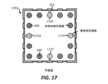
上述のように、相互接続のスタックは、側面相互接続352に結合されてよい(たとえば、電気的に結合されてよい)。図17は、いくつかの相互接続のスタック400と、いくつかの相互接続のスタック1710(たとえば、第1の相互接続の第1のスタック、第2の相互接続の第2のスタック、第3の相互接続の第3のスタック、第4の相互接続の第4のスタック)とを含む基板1702を示す。相互接続のスタック1710は、側面相互接続352に結合される(たとえば、直接タッチしている)。いくつかの実装形態では、相互接続のスタック1710は、1つまたは複数のエッジ相互接続(たとえば、エッジ相互接続1210)を介して側面相互接続352に結合される。図17に示すように、相互接続のスタック400および相互接続のスタック1710は、相互接続のスタック400および相互接続のスタック1710が、基板1202の周縁または外周の中に、周縁または外周においてまたはその付近に、少なくとも部分的に配置される(たとえば、相互接続のスタックの外側の行および/または外側の列の中に配置される)ように、基板1702内に配置されてよい。いくつかの実装形態では、相互接続のスタック400および1710は、側面相互接続352に最も近く配置された相互接続のスタックである。側面相互接続352は、側面相互接続352のそれぞれの部分がそれぞれの相互接続の第1のスタック400に近接または隣接するように、パターン化される。
As mentioned above, the stack of interconnects may be coupled (eg, electrically coupled) to the
いくつかの実装形態では、基板1202の周縁または外周付近の少なくとも大部分の相互接続のスタックは、非接地基準信号(たとえば、電力信号、入力/出力信号)に対する少なくとも1つの電気経路を設けるように構成された相互接続のスタックである。たとえば、少なくとも部分的に基板1202の周縁または外周内にある相互接続のスタックの大部分またはかなりの数もしくは割合(たとえば、約60パーセント以上、70パーセント以上、80パーセント以上)は、非接地基準信号(たとえば、電力信号、入力/出力信号)に対する少なくとも1つの電気経路を設けるように構成された相互接続のスタックである。
In some implementations, the stack of at least most interconnects near the perimeter or perimeter of
図18は基板1702の側面図を示し、そこにおいて、側面相互接続352の第1の部分が、側面相互接続352の第1の部分および第2の部分を接続するラテラル側面相互接続を介して、側面相互接続352の第2の部分に結合される。
FIG. 18 shows a side view of the
図15〜図18は、近くにある相互接続(たとえば、相互接続のスタック、相互接続レイアウト)の形態を少なくとも実質的に反映または模倣するようにパターン化された側面相互接続(たとえば、側面相互接続352)の例を示す。いくつかの実装形態では、側面相互接続は、近くにある相互接続の形態を正確に反映または模倣してよい。図15〜図18に示すように、いくつかの実装形態では、側面相互接続は、近くにある相互接続と、必ずしも同一であるとは限らないが同様にパターン化されてよい。いくつかの実装形態では、より複雑な形状または構造を反映または模倣するために、より簡単な形状が使用されてよい。たとえば、側面相互接続の長方形形状の部分が、ビアおよびパッドを備える相互接続のスタックの形状を反映または模倣するために使用されてよい。 15-18 are side interconnects (eg, side interconnects) that are patterned to at least substantially reflect or mimic the morphology of nearby interconnects (eg, interconnect stacks, interconnect layouts). An example of 352) is shown. In some implementations, the side interconnects may accurately reflect or mimic the morphology of nearby interconnects. As shown in FIGS. 15-18, in some implementations, side interconnections may be similarly patterned, if not necessarily identical, to nearby interconnects. In some implementations, simpler shapes may be used to reflect or mimic more complex shapes or structures. For example, the rectangular portion of the side interconnect may be used to reflect or mimic the shape of the interconnect stack with vias and pads.
図19は、基板1702内の相互接続のスタック400および相互接続のスタック1710の側面図を示す。相互接続のスタック1710は、側面相互接続352に結合される。異なる実装形態は、異なる構成および/または配列の相互接続を有する相互接続のスタック400と相互接続のスタック1710とを提供してよい。たとえば、相互接続のスタック1710は、表面相互接続350に直接的または間接的(たとえば、はんだボールを介して)のいずれかで結合されてよい。
FIG. 19 shows a side view of the
側面相互接続352は、表面相互接続350に結合されてよい(たとえば、タッチしてよい)ことに留意されたい。いくつかの実装形態では、側面相互接続352は、表面相互接続350とタッチしないかまたは直接タッチしない。
Note that the
基板のはんだレジスト層上の例示的な相互接続
図20は、基板のはんだレジスト層上の表面相互接続350の断面平面図を示す。表面相互接続350は、接地基準信号に対する電気経路を設けるように構成されてよい。表面相互接続350は、開口の第1のセット2002と、開口の第2のセット2004とを含む。開口の第1のセット2002は、1つまたは複数の開口(たとえば、空洞)を含んでよい。開口の第2のセット2004は、1つまたは複数の開口を含んでよい。開口の第1のセット2002内の開口(たとえば、空洞)は、第1の寸法(たとえば、第1の直径、第1の幅)を有する。開口の第2のセット2004内の開口は、第1の寸法より小さい第2の寸法(たとえば、第2の直径、第2の幅)を有する。
Exemplary Interconnects on the Solder Resist Layer of the Substrate FIG. 20 shows a cross-sectional plan view of the
図21は、はんだボールのセットが表面相互接続350の一部または全部の開口に配置された後の表面相互接続350の断面平面図を示す。はんだボールのセットは、ダイ(たとえば、ダイ304)を基板(たとえば、基板302)に結合するはんだボールとすることができる。図21は、開口の第1のセット2002内に配置されたはんだボールの第1のセット2102を示す。図21に示すように、はんだボールの第1のセット2102は、表面相互接続350に直接タッチしない(たとえば、接触していない)。いくつかの実装形態では、はんだボールの第1のセット2102は、少なくとも1つの信号(たとえば、第1の電力信号、第1の入力/出力信号、第2の入力/出力信号、など)に対する少なくとも1つの第1の電気経路を設けるように構成される。
FIG. 21 shows a cross-sectional plan view of the
また、図21は、開口の第2のセット2004内に配置されたはんだボールの第2のセット2104を示す。図21に示すように、はんだボールの第2のセット2104は、表面相互接続350に結合される(たとえば、直接タッチする、接触している)。いくつかの実装形態では、はんだボールの第2のセット2104は、少なくとも1つの第2の信号(たとえば、第1の非接地基準信号)に対する少なくとも1つの第2の電気経路を設けるように構成される。したがって、いくつかの実装形態では、はんだボールの第2のセット2104からの一部または全部のはんだボールは、異なる信号(たとえば、非接地基準信号)に対する電気経路を設けるように構成されてよい。
Also, FIG. 21 shows a second set of
上述のように、表面相互接続350は、いくつかの表面相互接続を含むパターン化金属層とすることができる。図22および図23は、パターン化表面相互接続2200の一例を示す。パターン化表面相互接続2200は、本開示で説明する表面相互接続350を置き換えてよい。パターン化表面相互接続2200は、パターン化表面相互接続の一例にすぎない。したがって、異なる実装形態は、異なる設計および/またはパターンを有するパターン化表面相互接続を利用してもよい。
As mentioned above, the
図22は、パターン化表面相互接続2200の断面平面図を示す。パターン化表面相互接続2200は、開口の第1のセット2002と開口の第2のセット2004とを含む。開口の第1のセット2002は、1つまたは複数の開口(たとえば、空洞)を含んでよい。開口の第2のセット2004は、1つまたは複数の開口を含んでよい。開口の第1のセット2002内の開口(たとえば、空洞)は、第1の寸法(たとえば、第1の直径、第1の幅)を有する。開口の第2のセット2004の開口は、第1の寸法より小さい第2の寸法(たとえば、第2の直径、第2の幅)を有する。
FIG. 22 shows a cross-sectional plan view of the patterned
図23は、はんだボールのセットがパターン化表面相互接続2200の一部または全部の開口内に配置された後のパターン化表面相互接続2200の断面平面図を示す。はんだボールのセットは、ダイ(たとえば、ダイ304)を基板(たとえば、基板302)に結合するはんだボールとすることができる。図23は、開口の第1のセット2002内に配置されたはんだボールの第1のセット2102を示す。図23に示すように、はんだボールの第1のセット2102は、パターン化表面相互接続2200に直接タッチしない(たとえば、接触していない)。いくつかの実装形態では、はんだボールの第1のセット2102は、少なくとも1つの第1の信号(たとえば、第1の接地基準信号)に対する少なくとも1つの第1の電気経路を設けるように構成される。
FIG. 23 shows a cross-sectional plan view of a patterned
また、図23は、開口の第1のセット2004内に配置されたはんだボールの第2のセット2104を示す。図23に示すように、はんだボールの第2のセット2104は、パターン化表面相互接続2200に結合されない(たとえば、直接タッチしない、接触していない)。いくつかの実装形態では、はんだボールの第2のセット2104は、少なくとも1つの第2の信号(たとえば、第1の電力信号、第1の入力/出力信号、第2の入力/出力信号、など)に対する少なくとも1つの第2の電気経路を設けるように構成される。したがって、いくつかの実装形態では、はんだボールの第2のセット2104からの一部または全部のはんだボールは、異なる信号(たとえば、非接地基準信号)に対する電気経路を設けるように構成されてよい。
Also, FIG. 23 shows a second set of
表面相互接続(たとえば、パターン化表面相互接続2200)は、近くにある相互接続(たとえば、パッケージ基板のトップレベル相互接続、ダイの相互接続、パッケージ基板の相互接続レイアウトおよび/またはダイの相互接続レイアウト)の設計および/または形態を少なくとも実質的に反映または模倣するようにパターン化される。いくつかの実装形態では、パッケージ基板のトップレベル相互接続は、パッケージ基板の上面に最も近いパッケージ基板内の少なくとも1つの相互接続である。いくつかの実装形態では、パッケージ基板のトップレベル相互接続は、パッケージ基板の上面に最も近いパッケージ基板内の少なくとも1つの金属層および/または少なくとも1つの導電層である。いくつかの実装形態では、表面相互接続は、近くにある相互接続の設計および/または形態を正確に反映または模倣してよい。いくつかの実装形態では、表面相互接続は、近くにある相互接続と、必ずしも同一であるとは限らないが同様にパターン化されてよい。いくつかの実装形態では、より複雑な設計、形状および/またはレイアウトを反映または模倣するために、より簡単なパターンおよび/または形状が使用されてよい。 Surface interconnects (eg, patterned surface interconnects 2200) are nearby interconnects (eg, package substrate top-level interconnects, die interconnects, package substrate interconnect layouts and / or die interconnect layouts. ) Is patterned to at least substantially reflect or mimic the design and / or form. In some implementations, the top-level interconnect of the package substrate is at least one interconnect in the package substrate that is closest to the top surface of the package substrate. In some implementations, the top-level interconnect of the package substrate is at least one metal layer and / or at least one conductive layer in the package substrate closest to the top surface of the package substrate. In some implementations, the surface interconnect may accurately reflect or mimic the design and / or form of nearby interconnects. In some implementations, surface interconnects may be similarly patterned, if not necessarily identical, to nearby interconnects. In some implementations, simpler patterns and / or shapes may be used to reflect or mimic more complex designs, shapes and / or layouts.
表面相互接続2200は、近くにある信号の分離を改善するようにパターン化されてよい。加えて、表面相互接続2200は、共振構造を設けてデバイス(たとえば、ダイ)の性能を改善するようにパターン化されてよい。いくつかの実装形態では、表面相互接続2200は、パッケージ基板内に空きスペースまたは空きエリアを作製してデバイスの性能を改善するようにパターン化されてよい。いくつかの実装形態では、表面相互接続2200は、いくつかの異なる接地基準信号に対するいくつかの電気経路を設けるように構成された別々の相互接続を作製するようにパターン化され、区分されてよい。たとえば、表面相互接続2200は、(1)第1の接地基準信号(たとえば、一般的接地基準信号)に対する第1の電気経路を設けるように構成された第1の表面相互接続と、(2)第2の接地基準信号(たとえば、アナログ接地基準信号)に対する第2の電気経路を設けるように構成された第2の表面相互接続と、(3)第3の接地基準信号(たとえば、デジタル接地基準信号)に対する第3の電気経路を設けるように構成された第3の表面相互接続と、(4)第4の接地基準信号(たとえば、無線周波数(RF)接地基準信号)に対する第4の電気経路を設けるように構成された第4の表面相互接続とにパターン化され、区分されてよい。いくつかの実装形態では、上記の表面相互接続のうちの1つまたは複数は、互に物理的にタッチしていない。
The
はんだレジスト層上に相互接続を備える基板へのダイの例示的な結合
図24は、ダイを基板に結合する(たとえば、取り付ける)シーケンスのクローズアップ図を示す。図24のステージ1は、第2の誘電体層322と、パッド332aと、第1のはんだレジスト層340と、表面相互接続350とを含む基板302の一部分のクローズアップ図を示す。表面相互接続350は、パッド332aと直接接触しない。図24のステージ2は、ダイ304が基板302に結合された後のクローズアップ図を示す。ステージ2に示すように、ダイ304のUBM層370aは、はんだボール310aに示されるように結合される。はんだボール310aは、パッド332aに結合される。はんだボール310aは、表面相互接続350と直接接触していない。いくつかの実装形態では、はんだボール310aおよびパッド332aは、第1の信号(たとえば、電力信号、入力/出力信号)に対する電気経路を設けるように構成される。
Illustrative Bonding of a Die to a Substrate with Interconnects on a Solder Resist Layer FIG. 24 shows a close-up view of a sequence of bonding (eg, mounting) a die to a substrate.
図25は、ダイを基板に結合する(たとえば、取り付ける)シーケンスのクローズアップ図を示す。図25のステージ1は、第2の誘電体層322と、パッド332bと、第1のはんだレジスト層340と、表面相互接続350とを含む基板302の別の一部分のクローズアップ図を示す。表面相互接続350は、パッド332bと直接には接触していない。図25のステージ2は、ダイ304が基板302に結合された後のクローズアップ図を示す。ステージ2に示すように、ダイ304のUBM層370bは、はんだボール310bに結合される。はんだボール310bは、パッド332bに結合される。はんだボール310bは、表面相互接続350に結合される(たとえば、直接接触している)。いくつかの実装形態では、はんだボール310b、パッド332b、および表面相互接続350は、第2の信号(たとえば、接地基準信号)に対する電気経路を設けるように構成される。
FIG. 25 shows a close-up view of the sequence of coupling (eg, mounting) the die to the substrate.
図26は、ダイを基板に結合する(たとえば、取り付ける)シーケンスのクローズアップ図を示す。図26のステージ1は、第2の誘電体層322と、パッド332cと、第1のはんだレジスト層340と、表面相互接続350とを含む基板302の別の一部分のクローズアップ図を示す。表面相互接続350は、パッド332cに結合される(たとえば、直接接触している)。図26のステージ2は、ダイ304が基板302に結合された後のクローズアップ図を示す。ステージ2に示すように、ダイ304のUBM層370cは、はんだボール310cに結合される。はんだボール310cは、パッド332cに結合される。また、はんだボール310cは、表面相互接続350に結合される(たとえば、直接接触している)。いくつかの実装形態では、はんだボール310c、パッド332c、および表面相互接続350は、第2の信号(たとえば、接地基準信号)に対する電気経路を設けるように構成される。
FIG. 26 shows a close-up view of the sequence of coupling (eg, mounting) the die to the substrate.
相互接続のスタック、はんだレジスト層上の相互接続および基板の側面部分上の相互接続を有する基板を備える集積デバイスパッケージを設ける/製作するための例示的なシーケンス
いくつかの実装形態では、相互接続のスタックと、表面相互接続と、側面相互接続とを有する基板(たとえば、パッケージ基板)を設ける/製作するステップは、いくつかのプロセスを含む。図27(図27A〜図27Cを含む)は、スタック化相互接続と、表面相互接続と、側面相互接続とを有する基板(たとえば、パッケージ基板)を設ける/製作するための例示的なシーケンスを示す。いくつかの実装形態では、図27A〜図27Cのシーケンスが、図2、図16の基板、および/または本開示で説明する他の基板を設ける/製作するために使用されてもよい。しかしながら、簡略化のために、図27A〜図27Cは、図2の基板を設ける/製作する文脈において説明されることになる。
An exemplary sequence for providing / manufacturing an integrated device package with a board having a stack of interconnects, interconnects on solder resist layers and interconnects on the sides of the board. In some implementations, interconnects. The step of providing / manufacturing a substrate having a stack, a surface interconnect, and a side interconnect (eg, a packaged substrate) involves several processes. FIG. 27 (including FIGS. 27A-27C) shows an exemplary sequence for providing / manufacturing a substrate (eg, a packaged substrate) having a stacked interconnect, a surface interconnect, and a side interconnect. .. In some implementations, the sequence of FIGS. 27A-27C may be used to provide / manufacture the substrate of FIGS. 2, 16 and / or the other substrates described herein. However, for the sake of brevity, FIGS. 27A-27C will be described in the context of providing / manufacturing the substrate of FIG.
図27A〜図27Cのシーケンスでは、基板を提供するためのシーケンスを簡略化しおよび/または明確化するために、1つまたは複数のステージを組み合わせてもよいことに留意されたい。いくつかの実装形態では、プロセスの順序は、変更または修正されてもよい。 It should be noted that in the sequences of FIGS. 27A-27C, one or more stages may be combined to simplify and / or clarify the sequence for providing the substrate. In some implementations, the order of the processes may be changed or modified.
図27Aのステージ1は、コア層2700が設けられた後の状態を示す。いくつかの実装形態では、コア層2700は、サプライヤによって提供される。いくつかの実装形態では、コア層2700は、製作される(たとえば、形成される)。コア層2700は、第1の誘電体層2702と、第1の金属層2704と、第2の金属層2706とを含む。第1の金属層2704は、第1の誘電体層2702の第1の表面(たとえば、上面)上にある。第2の金属層2706は、第1の誘電体層2702の第2の表面(たとえば、下面)上にある。
ステージ2は、いくつかの空洞がコア層2700内に形成された後の状態を示す。ステージ2に示すように、いくつかの空洞(たとえば、空洞2707)は、第1の誘電体層2702、第1の金属層2704、および第2の金属層2706の中に形成される。異なる実装形態は、空洞をコア層2700内に形成するために異なるプロセスを使用してもよい。いくつかの実装形態では、レーザプロセスおよび/またはフォトエッチングプロセス(たとえば、フォトリソグラフィ)が、空洞をコア層2700内に形成するために使用されてもよい。
ステージ3は、ビア(たとえば、ビア2708)が空洞(たとえば、空洞2707)内に形成された後の状態を示す。異なる実装形態は、ビアを空洞内に形成するために異なるプロセスを使用してもよい。いくつかの実装形態では、1つまたは複数のめっきプロセスが、ビアを形成するために使用されてもよい。いくつかの実装形態では、ペーストを使用してビアを形成してもよい。
ステージ4は、第1の金属層2704の部分および第2の金属層2706の部分が選択的に除去されて(たとえば、エッチングされて)1つまたは複数の相互接続(たとえば、トレース、パッド、エッジ相互接続)が画定された後の状態を示す。
In
ステージ5は、第2の誘電体層2710および第3の誘電体層2712がコア層2700上に形成された後の状態を示す。ステージ5に示すように、第2の誘電体層2710は第1の誘電体層2702の第1の表面の上に形成され、第3の誘電体層2712は第1の誘電体層2702の第2の表面の上に形成される。いくつかの実装形態では、第2および第3の誘電体層2710および2712は、プリプレグ層である。また、第1の誘電体層2702は、いくつかの実装形態ではプリプレグ層とすることができることに留意されたい。
図27Bに示すように、ステージ6は、いくつかの空洞(たとえば、空洞2711)が第2の誘電体層2710内に形成され(たとえば、作製され)、いくつかの空洞(たとえば、空洞2713)が第3の誘電体層2712内に形成された後の状態を示す。異なる実装形態は、誘電体層内に空洞を形成するために異なるプロセスを使用してもよい。いくつかの実装形態では、レーザプロセスおよび/またはフォトエッチングプロセス(たとえば、フォトリソグラフィ)が、空洞を誘電体層内に形成するために使用されてもよい。
As shown in FIG. 27B, in
ステージ7は、金属層2714が第2の誘電体層2710内/上に形成された後の状態を示す。第2の誘電体層2710の空洞内に形成された金属層2714は、ビアを画定してよい。第2の誘電体層2710上に形成された金属層2714は、1つまたは複数の相互接続(たとえば、トレース、パッド、エッジ相互接続)を画定してよい。
また、ステージ7は、金属層2716が第3の誘電体層2712内/上に形成されることを示す。第3の誘電体層2712の空洞内に形成された金属層2716は、ビアを画定してよい。第3の誘電体層2712上に形成された金属層2716は、1つまたは複数の相互接続(たとえば、トレース、パッド、エッジ相互接続)を画定してよい。異なる実装態様は、金属層を形成するために異なるプロセスを使用してもよい。いくつかの実装形態では、1つまたは複数のめっきプロセスが、金属層を形成するために使用されてもよい。いくつかの実装形態では、ペーストを使用して金属層(たとえば、ビア)を形成してもよい。
The
ステージ7は、少なくとも図3および図16において上記で前述したように、第1の誘電体層2702、第2の誘電体層2710、および/または第3の誘電体層2712内に形成された相互接続のうちのいくつかがスタック構成に配列され、それによって相互接続のスタックが形成されることを示す。
The
ステージ8は、第1のはんだレジスト層2720が、第2の誘電体層2710と、金属層2714の一部との上に形成された後の状態を示す。また、ステージ8は、第2のはんだレジスト層2722が、第3の誘電体層2712と、金属層2716の一部との上に形成された後の状態を示す。
Stage 8 shows the state after the first solder resist
ステージ9は、表面相互接続2730が、第1のはんだレジスト層2720の上に形成された後の状態を示す。表面相互接続2730は、パターン化表面相互接続とすることができる。いくつかの実装形態では、めっきプロセスが、表面相互接続2730を形成するために使用される。さらに、ステージ9は、側部表面相互接続2732が、基板の側面(たとえば、誘電体層の側面、はんだレジスト層)上に形成されることを示す。いくつかの実装形態では、側部表面相互接続2732は、パターン化側部表面相互接続である。いくつかの実装形態では、側部表面相互接続2732は、誘電体層内/上に形成されたエッジ相互接続の近くおよび/または周囲に画定されてよい。側部表面相互接続2732は、表面相互接続2730と同じ層とすることができる。いくつかの実装形態では、ステージ9は、基板の周縁の近くのおよび/または周縁におけるスタック化相互接続と、表面相互接続と、側面相互接続とを含む基板2750を示す。
ステージ10は、はんだボールのセット2760が、金属層2716から形成されたパッドに結合された後の状態を示す。いくつかの実装形態では、はんだボールのセット2760からの少なくとも大部分のはんだボールが、少なくとも1つの非接地基準信号に対する少なくとも1つの電気経路を設けるように構成される。いくつかの実装形態では、はんだボールのセット2760からの少なくともかなりの数(たとえば、70パーセント以上)のはんだボールが、少なくとも1つの非接地基準信号に対する少なくとも1つの電気経路を設けるように構成される。
The
ステージ11は、ダイ2770が、はんだボールのセット2780を介して基板2750に結合された後の状態を示す。
Stage 11 shows the state after the
相互接続のスタックと、はんだレジスト層上の相互接続と、基板の側面部分上の相互接続とを有する基板を備える集積デバイスパッケージを設ける/製作するための方法の例示的なフロー図
いくつかの実装形態では、相互接続のスタックと、表面相互接続と、側面相互接続とを有する基板(たとえば、パッケージ基板)を設ける/製作するステップは、いくつかのプロセスを含む。図28は、相互接続のスタックと、表面相互接続と、側面相互接続とを有する基板(たとえば、パッケージ基板)を設ける/製作するための方法2800の例示的なフロー図を示す。いくつかの実装形態では、図28の方法は、図3の基板、および/または本開示における他の基板を設ける/製作するためのものである。
An exemplary flow diagram of a method for providing / manufacturing an integrated device package with a board having a stack of interconnects, interconnects on a solder resist layer, and interconnects on the sides of the substrate. In the form, the step of providing / manufacturing a substrate having a stack of interconnects and a surface interconnect and a side interconnect (eg, a packaged substrate) involves several processes. FIG. 28 shows an exemplary flow diagram of
図28の方法が、集積デバイスを提供するためのシーケンスを簡略化および/または明確化するために、1つまたは複数のステップを組み合わせてもよいことに留意されたい。いくつかの実装形態では、プロセスの順序は、変更または修正されてもよい。 Note that the method of FIG. 28 may combine one or more steps to simplify and / or clarify the sequence for providing an integrated device. In some implementations, the order of the processes may be changed or modified.
この方法は、(2805において)いくつかの誘電体層を設ける。いくつかの実装形態では、いくつかの誘電体層を設けるステップは、コア層といくつかのプリプレグ層とを形成するステップを含む。いくつかの実装形態では、プリプレグ層だけが形成される。 This method provides several dielectric layers (at 2805). In some implementations, the step of providing some dielectric layers comprises forming a core layer and some prepreg layers. In some implementations, only the prepreg layer is formed.
この方法は、(2810において)誘電体層内に少なくとも1つの相互接続のスタックを形成する。相互接続のスタックは、2つ以上の相互接続を含んでもよい。相互接続は、トレース、パッド、および/またはビアを含んでもよい。相互接続のスタックは、スタック(たとえば、垂直スタック)内に実質的に配列されたいくつかの相互接続とすることができる。相互接続のスタックは、いくつかの誘電体層内/上に形成されてよい。相互接続のスタックのセットは、相互接続のスタックが、基板の周縁または外周において、周縁または外周の付近に、またはその中に、少なくとも部分的に配置されるように、誘電体層内に配置されてよい。相互接続のスタックは、相互接続のスタックの外側の行および/または外側の列の中に配列されてよい。相互接続の第1のスタックは、少なくとも1つの第1の非接地基準信号に対する電気経路を設けるように構成されてよい。相互接続の第2のスタックは、少なくとも1つの接地基準信号に対する電気経路を設けるように構成されてよい。相互接続のスタックの例(たとえば、相互接続のスタック400、410)は、少なくとも図4において上記で説明されている。異なる実装形態は、相互接続と相互接続のスタックとを別様に形成してもよい。いくつかの実装形態では、めっきプロセスが、相互接続と相互接続のスタックとを形成するために使用される。相互接続(たとえば、相互接続のスタック)を形成するステップの例が、少なくとも以下の図29〜図32において詳細に説明される。 This method forms a stack of at least one interconnect within the dielectric layer (at 2810). The interconnect stack may include two or more interconnects. The interconnect may include traces, pads, and / or vias. The stack of interconnects can be several interconnects that are substantially arranged within the stack (eg, a vertical stack). The interconnect stack may be formed in / on several dielectric layers. The set of interconnect stacks is arranged within the dielectric layer such that the interconnect stacks are at least partially located on or near the periphery or perimeter of the substrate at or within the perimeter or perimeter of the substrate. You can. The interconnect stack may be arranged in the outer rows and / or outer columns of the interconnect stack. The first stack of interconnects may be configured to provide an electrical path to at least one first ungrounded reference signal. The second stack of interconnects may be configured to provide electrical paths for at least one ground reference signal. Examples of interconnect stacks (eg, interconnect stacks 400, 410) are described above at least in FIG. Different implementations may form interconnects and interconnect stacks differently. In some implementations, the plating process is used to form interconnects and interconnect stacks. Examples of steps for forming an interconnect (eg, a stack of interconnects) are described in detail at least in FIGS. 29-32 below.
この方法は、(2815において)少なくとも1つのエッジ相互接続を随意で形成する。エッジ相互接続は、1つまたは複数の相互接続のスタックに結合するように形成されてよい。エッジ相互接続の例は、少なくとも図12〜図14において上記で説明されている。相互接続(たとえば、エッジ相互接続)を形成するステップの例は、少なくとも以下の図29〜図32において詳細に説明される。 This method optionally forms at least one edge interconnect (at 2815). Edge interconnects may be formed to combine into a stack of one or more interconnects. Examples of edge interconnects are described above at least in FIGS. 12-14. Examples of steps for forming interconnects (eg, edge interconnects) are described in detail at least in FIGS. 29-32 below.
この方法は、(2820において)誘電体層のうちの少なくとも1つの上でパッドを形成する。パッドは、基板のダイ側のパッド(たとえば、ダイ側のはんだボールパッド)および/またはプリント回路板(PCB)側のパッド(たとえば、PCB側のはんだボールパッド)とすることができる。大部分、または実質的に大部分(たとえば、60パーセント以上)のパッドが、少なくとも1つの非接地基準信号に対する少なくとも1つの電気経路を設けるように構成される。 This method forms a pad on at least one of the dielectric layers (at 2820). The pad can be a pad on the die side of the substrate (eg, a solder ball pad on the die side) and / or a pad on the printed circuit board (PCB) side (eg, a solder ball pad on the PCB side). Most, or substantially most (eg, 60 percent or more) pads are configured to provide at least one electrical path for at least one ungrounded reference signal.
この方法は、(2825において)1つまたは複数の誘電体層上に少なくとも1つのはんだレジスト層を形成する。 This method forms at least one solder resist layer on one or more dielectric layers (at 2825).
また、この方法は、(2830において)はんだレジスト層上に表面相互接続を形成する。表面相互接続は、パターン化金属層とすることができる。表面相互接続は、接地基準信号を与えるように構成されてよい。 This method also forms a surface interconnect (at 2830) on the solder resist layer. The surface interconnect can be a patterned metal layer. The surface interconnect may be configured to provide a ground reference signal.
この方法は、(2835において)基板の側面上に側面相互接続を形成する。側面相互接続は、パターン化金属層とすることができる。側面相互接続は、接地基準信号を与えるように構成されてよい。側面相互接続は、表面相互接続に結合されてよい(たとえば、接触してよい)。いくつかの実装形態では、側面相互接続は、1つまたは複数の相互接続のスタック(たとえば、接地基準信号に対する電気経路を設けるように構成された相互接続のスタック)に結合されてよい。 This method forms a side interconnection (at 2835) on the sides of the substrate. The side interconnection can be a patterned metal layer. The side interconnections may be configured to provide a ground reference signal. Side interconnects may be coupled (eg, contact) to surface interconnects. In some implementations, side interconnects may be coupled to a stack of one or more interconnects (eg, a stack of interconnects configured to provide an electrical path to a ground reference signal).
この方法は、(2840において)はんだボールをパッドに供給する。はんだボールのうちのいくつかは、接地基準信号に対する電気経路を設けるように構成されてよい。大部分のはんだボールは、少なくとも1つの非接地基準信号(たとえば、電力信号、入力/出力信号)に対する少なくとも1つの電気経路を設けるように構成されてよい。 This method feeds the pad with solder balls (at 2840). Some of the solder balls may be configured to provide an electrical path to the ground reference signal. Most solder balls may be configured to provide at least one electrical path for at least one ungrounded reference signal (eg, power signal, input / output signal).
例示的なセミアディティブパターニング(SAP)プロセス
様々な相互接続(たとえば、トレース、ビア、パッド)および金属層が、本開示で説明される。いくつかの実装形態では、これらの相互接続は、1つまたは複数の金属層を含んでもよい。たとえば、いくつかの実装形態では、これらの相互接続は、第1の金属シード層と第2の金属層とを含んでよい。金属層は、異なるめっきプロセスを使用して設けられてよい(たとえば、形成されてよい)。シード層を有する相互接続(たとえば、トレース、ビア、パッド)の例、およびこれらの相互接続が異なるめっきプロセスを使用してどのように形成され得るかについて、以下で詳述される。
Exemplary Semi-Additive Patterning (SAP) Processes Various interconnects (eg, traces, vias, pads) and metal layers are described herein. In some implementations, these interconnects may include one or more metal layers. For example, in some implementations, these interconnects may include a first metal seed layer and a second metal layer. The metal layer may be provided using different plating processes (eg, may be formed). Examples of interconnects with seed layers (eg, traces, vias, pads) and how these interconnects can be formed using different plating processes are described in detail below.
異なる実装形態は、金属層(たとえば、相互接続、表面相互接続、側面相互接続)を形成および/または製作するために異なるプロセスを使用してもよい。いくつかの実装形態では、これらのプロセスは、セミアディティブパターニング(SAP)プロセスとダマシンプロセスとを含む。これらの様々な異なるプロセスについて、以下でさらに説明される。 Different implementations may use different processes to form and / or fabricate metal layers (eg, interconnects, surface interconnects, side interconnects). In some implementations, these processes include semi-additive patterning (SAP) processes and damascene processes. These various different processes are further described below.
図29は、1つまたは複数の誘電体層内に相互接続を設けるおよび/または形成するためにセミアディティブパターニング(SAP)プロセスを使用して相互接続を形成するためのシーケンスを示す。図29に示すように、ステージ1は、誘電体層2902が設けられた(たとえば、形成された)後の集積デバイス(たとえば、基板)の状態を示す。いくつかの実装形態では、ステージ1は、誘電体層2902が第1の金属層2904を含むことを示す。第1の金属層2904は、いくつかの実装形態ではシード層である。いくつかの実装形態では、第1の金属層2904は、誘電体層2902が設けられた(たとえば、受け取られたまたは形成された)後に、誘電体層2902上に設けられ得る(たとえば、形成され得る)。ステージ1は、第1の金属層2904が誘電体層2902の第1の表面上に設けられる(たとえば、形成される)ことを示す。いくつかの実装形態では、第1の金属層2904は、堆積プロセス(たとえば、PVD、CVD、めっきプロセス)を使用することによって設けられる。
FIG. 29 shows a sequence for forming an interconnect using a semi-additive patterning (SAP) process to provide and / or form an interconnect within one or more dielectric layers. As shown in FIG. 29,
ステージ2は、フォトレジスト層2906(たとえば、フォト現像レジスト層)が第1の金属層2904上に選択的に設けられた(たとえば、形成された)後の集積デバイスの状態を示す。いくつかの実装形態では、レジスト層2906を選択的に設けることは、第1の金属層2904上に第1のレジスト層2906を設けることと、(たとえば、現像プロセスを使用して)現像することによってレジスト層2906の部分を選択的に除去することとを含む。ステージ2は、空洞2908が形成されるようにレジスト層2906が設けられることを示す。
ステージ3は、第2の金属層2910が空洞2908内に形成された後の集積デバイスの状態を示す。いくつかの実装形態では、第2の金属層2910は、第1の金属層2904の露出部分の上に形成される。いくつかの実装形態では、第2の金属層2910は、堆積プロセス(たとえば、めっきプロセス)を使用することによって設けられる。
ステージ4は、レジスト層2906が除去された後の集積デバイスの状態を示す。異なる実装形態は、レジスト層2906を除去するための異なるプロセスを使用してもよい。
ステージ5は、第1の金属層2904の一部が選択的に除去された後の集積デバイスの状態を示す。いくつかの実装形態では、第2の金属層2910によって覆われていない第1の金属層2904の1つまたは複数の部分は、除去される。ステージ5に示すように、残りの第1の金属層2904および第2の金属層2910は、集積デバイスおよび/または基板内の相互接続2912(たとえば、トレース、ビア、パッド)を形成および/または画定することができる。いくつかの実装形態では、第1の金属層2904は、第2の金属層2910の下にある第1の金属層2904の寸法(たとえば、長さ、幅)が第2の金属層2910の寸法(たとえば、長さ、幅)とほぼ同じかまたはそれより小さくなるように除去され、これは、図29のステージ5に示すように、アンダーカットをもたらすことができる。いくつかの実装形態では、前述のプロセスは、集積デバイスおよび/または基板の1つまたは複数の誘電体層内にいくつかの相互接続を設けるおよび/または形成するために、複数回繰り返されてもよい。
図30は、1つまたは複数の誘電体層内に相互接続を設けるおよび/または形成するために(SAP)プロセスを使用するための方法のフロー図を示す。方法は、(3005で)誘電体層(たとえば、誘電体層2902)を設ける。いくつかの実装形態では、誘電体層を設けるステップは、誘電体層を形成するステップを含む。いくつかの実装形態では、誘電体層を設けるステップは、第1の金属層(たとえば、第1の金属層2904)を形成するステップを含む。第1の金属層は、いくつかの実装形態では、シード層である。いくつかの実装形態では、第1の金属層は、誘電体層が設けられた(たとえば、受け取られたまたは形成された)後、誘電体層上に設けられてもよい(たとえば、形成されてもよい)。いくつかの実装形態では第1の金属層は、堆積プロセス(たとえば、物理気相堆積(PVD)またはめっきプロセス)を使用することによって設けられる。 FIG. 30 shows a flow diagram of a method for using the (SAP) process to provide and / or form interconnects within one or more dielectric layers. The method provides a dielectric layer (eg, a dielectric layer 2902) (at 3005). In some implementations, the step of providing the dielectric layer comprises the step of forming the dielectric layer. In some implementations, the step of providing the dielectric layer comprises forming a first metal layer (eg, first metal layer 2904). The first metal layer is, in some implementations, a seed layer. In some implementations, the first metal layer may be provided (eg, formed) on the dielectric layer after the dielectric layer has been provided (eg, received or formed). May be good). In some implementations, the first metal layer is provided by using a deposition process (eg, physical vapor deposition (PVD) or plating process).
方法は、(3010で)第1の金属層上にフォトレジスト層(たとえば、フォト現像レジスト層2906)を選択的に設ける。いくつかの実装形態では、レジスト層を選択的に設けるステップは、第1の金属層上に第1のレジスト層を設けるステップと、(1つまたは複数の空洞を提供する)レジスト層の部分を選択的に除去するステップとを含む。 The method selectively provides a photoresist layer (eg, a photoresist layer 2906) on top of the first metal layer (at 3010). In some implementations, the step of selectively providing the resist layer is a step of providing the first resist layer on the first metal layer and a portion of the resist layer (providing one or more cavities). Includes steps to selectively remove.
方法は、次いで、(3015で)フォトレジスト層の空洞内に第2の金属層(たとえば、第2の金属層2910)を設ける。いくつかの実装形態では、第2の金属層は、第1の金属層の露出部分の上に形成される。いくつかの実装形態では、第2の金属層は、堆積プロセス(たとえば、めっきプロセス)を使用することによって設けられる。 The method then provides a second metal layer (eg, a second metal layer 2910) within the cavity of the photoresist layer (at 3015). In some implementations, the second metal layer is formed on the exposed portion of the first metal layer. In some implementations, the second metal layer is provided by using a deposition process (eg, a plating process).
方法は、さらに、(3020で)レジスト層を除去する。異なる実装形態は、レジスト層を除去するための異なるプロセスを使用してもよい。方法はまた、(3025で)第1の金属層の一部を選択的に除去する。いくつかの実装形態では、第2の金属層によって覆われていない第1の金属層の1つまたは複数の部分が除去される。いくつかの実装形態では、任意の残りの第1の金属層および第2の金属層は、集積デバイスおよび/または基板内に1つまたは複数の相互接続(たとえば、トレース、ビア、パッド)を形成および/または画定することができる。いくつかの実装形態では、前述の方法は、集積デバイスおよび/または基板の1つまたは複数の誘電体層内にいくつかの相互接続を設けるおよび/または形成するために、複数回繰り返されてもよい。 The method further removes the resist layer (at 3020). Different implementations may use different processes to remove the resist layer. The method also selectively removes a portion of the first metal layer (at 3025). In some implementations, one or more portions of the first metal layer that are not covered by the second metal layer are removed. In some implementations, any remaining first and / or second metal layers form one or more interconnects (eg, traces, vias, pads) within the integrated device and / or substrate. And / or can be defined. In some implementations, the aforementioned method may be repeated multiple times to provide and / or form several interconnects within one or more dielectric layers of the integrated device and / or substrate. good.
例示的なダマシンプロセス
図31は、誘電体層内に相互接続を設けるおよび/または形成するためにダマシンプロセスを使用して相互接続を形成するためのシーケンスを示す。図31に示すように、ステージ1は、誘電体層3102が設けられた(たとえば、形成された)後の集積デバイスの状態を示す。いくつかの実装形態では、誘電体層3102は、無機層(たとえば、無機膜)である。
An exemplary damascene process FIG. 31 shows a sequence for forming an interconnect using a damascene process to provide and / or form an interconnect within a dielectric layer. As shown in FIG. 31,
ステージ2は、空洞3104が誘電体層3102内に形成された後の集積デバイスの状態を示す。異なる実装形態は、誘電体層3102内に空洞3104を設けるための異なるプロセスを使用してもよい。
ステージ3は、第1の金属層3106が誘電体層3102上に設けられた後の集積デバイスの状態を示す。図3に示すように、第1の金属層3106は、誘電体層3102の第1の表面上に設けられる。第1の金属層3106は、第1の金属層3106が空洞3104の輪郭を含む誘電体層3102の輪郭をとるように、誘電体層3102上に設けられる。第1の金属層3106は、いくつかの実装形態では、シード層である。いくつかの実装形態では、第1の金属層3106は、堆積プロセス(たとえば、物理気相堆積(PVD)、化学気相堆積(CVD)、またはめっきプロセス)を使用することによって設けられる。
ステージ4は、第2の金属層3108が空洞3104および誘電体層3102の表面内に形成された後の集積デバイスの状態を示す。いくつかの実装形態では、第2の金属層3108は、第1の金属層3106の露出部分の上に形成される。いくつかの実装形態では、第2の金属層3108は、堆積プロセス(たとえば、めっきプロセス)を使用することによって設けられる。
ステージ5は、第2の金属層3108の一部および第1の金属層3106の一部が除去された後の集積デバイスの状態を示す。異なる実装形態は、第2の金属層3108と第1の金属層3106とを除去するための異なるプロセスを使用してもよい。いくつかの実装形態では、化学機械研磨(CMP:chemical mechanical planarization)プロセスは、第2の金属層3108の一部と第1の金属層3106の一部とを除去するために使用される。ステージ5に示すように、残りの第1の金属層3106および第2の金属層3108は、集積デバイスおよび/または基板内の相互接続3112(たとえば、トレース、ビア、パッド)を形成および/または画定することができる。ステージ5に示すように、相互接続3112は、第1の金属層3106が第2の金属層3108のベース部分および側面部分上に形成されるようにして形成される。いくつかの実装形態では、空洞3104は、ビアおよび相互接続(たとえば、金属トレース)が単一の堆積ステップにおいて形成され得るように、2つのレベルの誘電体におけるトレンチおよび/またはホールの組合せを含んでもよい。いくつかの実装形態では、前述のプロセスは、集積デバイスおよび/または基板の1つまたは複数の誘電体層内にいくつかの相互接続を設けるおよび/または形成するために、複数回繰り返されてもよい。
図32は、誘電体層内に相互接続を設けるおよび/または形成するためにダマシンプロセスを使用して相互接続を形成するための方法3200のフロー図を示す。方法は、(3205で)誘電体層(たとえば、誘電体層3102)を設ける。いくつかの実装形態では、誘電体層を設けるステップは、誘電体層を形成するステップを含む。いくつかの実装形態では、誘電体層を設けるステップは、供給業者から誘電体層を受け取るステップを含む。いくつかの実装形態では、誘電体層は、無機層(たとえば、無機膜)である。
FIG. 32 shows a flow diagram of
方法は、(3210で)誘電体層内に少なくとも1つの空洞(たとえば、空洞3104)を形成する。異なる実装形態は、誘電体層内に空洞を設けるための異なるプロセスを使用してもよい。 The method forms at least one cavity (eg, cavity 3104) in the dielectric layer (at 3210). Different implementations may use different processes for providing cavities within the dielectric layer.
方法は、(3215で)誘電体層上に第1の金属層(たとえば、第1の金属層3106)を設ける。いくつかの実装形態では、第1の金属層は、誘電体層の第1の表面上に設けられる(たとえば、形成される)。いくつかの実装形態では、第1の金属層は、第1の金属層が空洞の輪郭を含む誘電体層の輪郭をとるように、誘電体層上に設けられる。第1の金属層は、いくつかの実装形態では、シード層である。いくつかの実装形態では、第1の金属層3106は、堆積プロセス(たとえば、PVD、CVD、またはめっきプロセス)を使用することによって設けられる。
The method provides a first metal layer (eg, a first metal layer 3106) on a dielectric layer (at 3215). In some implementations, the first metal layer is provided (eg, formed) on the first surface of the dielectric layer. In some implementations, the first metal layer is provided on the dielectric layer such that the first metal layer outlines the dielectric layer, including the contour of the cavity. The first metal layer is, in some implementations, a seed layer. In some implementations, the
方法は、(3220で)誘電体層の空洞および表面内に金属層(たとえば、第2の金属層3108)を設ける。いくつかの実装形態では、第2の金属層は、第1の金属層の露出部分の上に形成される。いくつかの実装形態では、第2の金属層は、堆積プロセス(たとえば、めっきプロセス)を使用することによって設けられる。いくつかの実装形態では、第2の金属層は、第1の金属層と同様または同一である。いくつかの実装形態では、第2の金属層は、第1の金属層とは異なる。 The method provides a metal layer (eg, a second metal layer 3108) within the cavity and surface of the dielectric layer (at 3220). In some implementations, the second metal layer is formed on the exposed portion of the first metal layer. In some implementations, the second metal layer is provided by using a deposition process (eg, a plating process). In some implementations, the second metal layer is similar to or identical to the first metal layer. In some implementations, the second metal layer is different from the first metal layer.
方法は次いで、(3225で)第2の金属層の一部と第1の金属層の一部とを除去する。異なる実装形態は、第2の金属層と第1の金属層とを除去するための異なるプロセスを使用してもよい。いくつかの実装形態では、化学機械研磨(CMP)プロセスは、第2の金属層の一部と第1の金属層の一部とを除去するために使用される。いくつかの実装形態では、残りの第1の金属層および第2の金属層は、相互接続(たとえば、相互接続3112)を形成および/または画定することができる。いくつかの実装形態では、相互接続は、少なくとも、集積デバイスおよび/または基板内の、トレース、ビア、および/またはパッドのうちの1つを含んでもよい。いくつかの実装形態では、相互接続は、第1の金属層が第2の金属層のベース部分および側面部分上に形成されるようにして形成される。いくつかの実装形態では、前述の方法は、集積デバイスおよび/または基板の1つまたは複数の誘電体層内にいくつかの相互接続を設けるおよび/または形成するために、複数回繰り返されてもよい。 The method then removes part of the second metal layer and part of the first metal layer (at 3225). Different implementations may use different processes for removing the second metal layer and the first metal layer. In some embodiments, a chemical mechanical polishing (CMP) process is used to remove a portion of the second metal layer and a portion of the first metal layer. In some implementations, the remaining first and second metal layers can form and / or define interconnects (eg, interconnect 3112). In some implementations, the interconnect may include at least one of the traces, vias, and / or pads within the integrated device and / or board. In some implementations, the interconnect is formed such that the first metal layer is formed on the base and side portions of the second metal layer. In some implementations, the aforementioned method may be repeated multiple times to provide and / or form several interconnects within one or more dielectric layers of the integrated device and / or substrate. good.
例示的な電子デバイス
図33は、上述の集積デバイス、半導体デバイス、集積回路、ダイ、インターポーザ、パッケージ、またはパッケージオンパッケージ(PoP)のいずれかと統合され得る様々な電子デバイスを示す。たとえば、モバイル電話デバイス話3302、ラップトップコンピュータデバイス3304、および固定位置端末デバイス3306が、本明細書で説明する集積デバイス3300を含んでもよい。集積デバイス3300は、たとえば、本明細書で説明した集積回路、ダイ、集積デバイス、集積デバイスパッケージ、集積回路デバイス、パッケージオンパッケージデバイスのうちのいずれかとすることができる。図33に示すデバイス3302、3304、3306は例にすぎない。また、他の電子デバイスは、限定はしないが、モバイルデバイス、ハンドヘルドパーソナル通信システム(PCS)ユニット、携帯情報端末などのポータブルデータユニット、全地球測位システム(GPS)対応デバイス、ナビゲーションデバイス、セットトップボックス、音楽プレーヤ、ビデオプレーヤ、娯楽ユニット、メータ読取り機器などの固定位置データユニット、通信デバイス、スマートフォン、タブレットコンピュータ、コンピュータ、ウェアラブルデバイス、サーバ、ルータ、自動車車両(たとえば、自律走行車両)内に実装された電子デバイス、またはデータもしくはコンピュータ命令を記憶し、もしくは取り出す任意の他のデバイス、あるいはそれらの任意の組合せを含むデバイス(たとえば、電子デバイス)のグループを含む集積デバイス3300を特徴とする場合がある。
Illustrative Electronic Devices Figure 33 shows various electronic devices that can be integrated with any of the integrated devices, semiconductor devices, integrated circuits, dies, interposers, packages, or package-on-packages (PoPs) described above. For example, the mobile
図3、図4、図5、図6、図7、図8、図9、図10、図11、図12、図13、図14、図15、図16、図17、図18、図19、図20、図21、図22、図23、図24、図25、図26、図27A〜図27C、図28、図29、図30、図31、図32、および/または図33に示す構成要素、ステップ、特徴および/または機能のうちの1つまたは複数は、単一の構成要素、ステップ、特徴または機能に再構成および/または結合されてよく、あるいは、いくつかの構成要素、ステップ、または機能で具現化されてよい。追加の要素、構成要素、ステップ、および/または機能も、本開示から逸脱することなく追加され得る。本開示における図3、図4、図5、図6、図7、図8、図9、図10、図11、図12、図13、図14、図15、図16、図17、図18、図19、図20、図21、図22、図23、図24、図25、図26、図27A〜図27C、図28、図29、図30、図31、図32、および/または図33、ならびにそれの対応する説明は、ダイおよび/またはICに限定されないことにも留意されたい。いくつかの実装形態では、図3、図4、図5、図6、図7、図8、図9、図10、図11、図12、図13、図14、図15、図16、図17、図18、図19、図20、図21、図22、図23、図24、図25、図26、図27A〜図27C、図28、図29、図30、図31、図32、および/または図33、ならびにそれの対応する説明は、集積デバイスを製作、作製、提供、および/または生産するために使用されてよい。いくつかの実装形態では、デバイスは、ダイ、ダイパッケージ、集積回路(IC)、集積デバイス、集積デバイスパッケージ、ウエハ、半導体デバイス、パッケージオンパッケージ、パッケージ基板、および/またはインターポーザを含む場合がある。 3, FIG. 4, FIG. 5, FIG. 6, FIG. 7, FIG. 8, FIG. 9, FIG. 10, FIG. 11, FIG. 12, FIG. 13, FIG. 14, FIG. 15, FIG. 16, FIG. 17, FIG. 18, FIG. 20, FIG. 21, FIG. 22, FIG. 23, FIG. 24, FIG. 25, FIG. 26, FIGS. 27A to 27C, FIG. 28, FIG. 29, FIG. 30, FIG. 31, FIG. 32, and / or FIG. 33. One or more of the components, steps, features and / or functions may be reconstructed and / or combined into a single component, step, feature or function, or several components, steps. , Or may be embodied in function. Additional elements, components, steps, and / or functions may also be added without departing from the present disclosure. 3, FIG. 4, FIG. 5, FIG. 6, FIG. 7, FIG. 8, FIG. 9, FIG. 10, FIG. 11, FIG. 12, FIG. 13, FIG. 14, FIG. 15, FIG. 16, FIG. 17, FIG. 18 in the present disclosure. 19, FIG. 20, FIG. 21, FIG. 22, FIG. 23, FIG. 24, FIG. 25, FIG. 26, FIGS. 27A to 27C, FIG. 28, FIG. 29, FIG. 30, FIG. 31, FIG. 32, and / or FIG. It should also be noted that 33, and its corresponding description, is not limited to dies and / or ICs. In some implementations, FIG. 3, FIG. 4, FIG. 5, FIG. 6, FIG. 7, FIG. 8, FIG. 9, FIG. 10, FIG. 11, FIG. 12, FIG. 13, FIG. 14, FIG. 15, FIG. 17, FIG. 18, FIG. 19, FIG. 20, FIG. 21, FIG. 22, FIG. 23, FIG. 24, FIG. 25, FIG. 26, FIGS. 27A to 27C, FIG. 28, FIG. 29, FIG. 30, FIG. 31, FIG. 32, And / or FIG. 33, and its corresponding description, may be used to manufacture, manufacture, provide, and / or produce an integrated device. In some embodiments, the device may include a die, die package, integrated circuit (IC), integrated device, integrated device package, wafer, semiconductor device, package-on-package, package substrate, and / or interposer.
「例示的」という語は、本明細書では「例、事例、または例示としての役割を果たすこと」を意味するために使用される。「例示的」として本明細書において説明される任意の実装形態または態様は、必ずしも本開示の他の態様よりも好ましいか、または有利であると解釈されるべきではない。同様に、「態様」という用語は、本開示のすべての態様が、論じられる特徴、利点、または動作モードを含むことを必要としない。「結合された」という用語は、本明細書において、2つの物体間の直接または間接的な結合を指すために使用される。たとえば、物体Aが物体Bに物理的に接触し、物体Bが物体Cに接触する場合、物体Aと物体Cとは、互いに物理的に直接接触していない場合でも、それでも互いに結合されていると見なされ得る。 The term "exemplary" is used herein to mean "act as an example, case, or example." Any implementation or embodiment described herein as "exemplary" should not necessarily be construed as preferred or advantageous over the other aspects of the present disclosure. Similarly, the term "aspect" does not require that all aspects of the present disclosure include the features, advantages, or modes of operation discussed. The term "bonded" is used herein to refer to a direct or indirect bond between two objects. For example, when the object A is in physical contact with the object B and the object B is in contact with the object C, the object A and the object C are still connected to each other even if they are not in direct physical contact with each other. Can be considered.
物体の「セット」は、1つまたは複数の物体を含んでもよい。たとえば、相互接続のセットは、1つまたは複数の相互接続を含んでもよい。はんだボールのセットは、1つまたは複数のはんだボールを含んでもよい。ビアのセットは、1つまたは複数のビアを含んでもよい。パッドのセットは、1つまたは複数のパッドを含んでもよい。相互接続のスタックのセットは、1つまたは複数の相互接続のスタックを含んでもよい。 A "set" of objects may include one or more objects. For example, a set of interconnects may include one or more interconnects. The set of solder balls may include one or more solder balls. The set of vias may include one or more vias. The set of pads may include one or more pads. A set of interconnect stacks may include one or more interconnect stacks.
また、実施形態は、フローチャート、流れ図、構造線図またはブロック図として描かれているプロセスとして記述され得ることに留意されたい。フローチャートは、動作を逐次プロセスとして説明し得るが、動作の多くは、並列にまたは同時に実行され得る。加えて、動作の順序は並べ替えられ得る。プロセスは、その動作が完了したとき、終了される。 It should also be noted that embodiments may be described as processes depicted as flowcharts, flow diagrams, structural diagrams or block diagrams. Flow charts can describe actions as sequential processes, but many of the actions can be performed in parallel or simultaneously. In addition, the order of operations can be rearranged. The process is terminated when its operation is complete.
本明細書で説明した本開示の様々な特徴は、本開示から逸脱することなく様々なシステムにおいて実装され得る。本開示の上記の態様は例にすぎず、本開示を限定するものとして解釈されるべきではないことに留意されたい。本開示の態様の説明は、例示的であることを意図しており、特許請求の範囲を限定することを意図していない。したがって、本教示は、他のタイプの装置に容易に適用されることが可能であり、多くの代替、修正、および変形が当業者には明らかとなろう。 The various features of the present disclosure described herein can be implemented in various systems without departing from the present disclosure. It should be noted that the above aspects of this disclosure are examples only and should not be construed as limiting this disclosure. The description of aspects of the present disclosure is intended to be exemplary and not intended to limit the scope of the claims. Accordingly, this teaching can be readily applied to other types of equipment, and many alternatives, modifications, and variations will be apparent to those of skill in the art.
100 ダイ
102 基板
104 はんだボールのセット
106 プリント回路板(PCB)
260 はんだボールのセット
300 集積デバイスパッケージ
302 基板
304 ダイ
310 はんだボールの第1のセット
310a はんだボール
310b はんだボール
310c はんだボール
320 第1の誘電体層
322 第2の誘電体層
324 第3の誘電体層
330 相互接続の第1のセット
332 相互接続の第2のセット
332a パッド
332b パッド
332c パッド
334 相互接続の第3のセット
340 第1のはんだレジスト層
342 第2のはんだレジスト層
350 表面相互接続
352 側面相互接続
360 はんだボールの第1のセット
360a はんだボール
360b はんだボール
270 アンダーバンプメタライゼーション(UBM)層
370a UBM層
370b UBM層
370c UBM層
380 相互接続の第1のスタックのセット
390 相互接続の第2のスタックのセット
400 相互接続の第1のスタック
402 相互接続
403 ビア
404 相互接続
405 ビア
406 相互接続
407 ビア
408 相互接続
410 相互接続の第2のスタック
412 相互接続
413 ビア
414 相互接続
415 ビア
416 相互接続
417 ビア
418 相互接続
500 基板
510 相互接続のセット
520 相互接続
902 第1の相互接続
904 第2の相互接続
910 第3の相互接続
1102 第3の相互接続
1104 第4の相互接続
1200 集積デバイスパッケージ
1202 基板
1210 エッジ相互接続
1211 エッジ相互接続
1212 エッジ相互接続
1213 エッジ相互接続
1214 エッジ相互接続
1215 エッジ相互接続
1216 エッジ相互接続
1600 相互接続のスタック
1702 基板
1710 相互接続のスタック
2002 開口の第1のセット
2004 開口の第2のセット
2102 はんだボールの第1のセット
2104 はんだボールの第2のセット
2200 パターン化表面相互接続
2700 コア層
2702 第1の誘電体層
2704 第1の金属層
2706 第2の金属層
2707 空洞
2708 ビア
2710 第2の誘電体層
2711 空洞
2712 第3の誘電体層
2713 空洞
2714 金属層
2716 金属層
2720 第1のはんだレジスト層
2722 第2のはんだレジスト層
2730 表面相互接続
2732 側部表面相互接続
2750 基板
2760 はんだボールのセット
2770 ダイ
2780 はんだボールのセット
2902 誘電体層
2904 第1の金属層
2906 フォトレジスト層、第1のレジスト層
2908 空洞
2910 第2の金属層
2912 相互接続
3102 誘電体層
3104 空洞
3106 第1の金属層
3108 第2の金属層
3112 相互接続
3300 集積デバイス
3302 モバイル電話デバイス
3304 ラップトップコンピュータデバイス
3306 固定位置端末デバイス
100 Die 102
260 Solder ball set 300 Integrated device package 302 Board 304 Die 310 First set of solder balls 310a Solder ball 310b Solder ball 310c Solder ball 320 First dielectric layer 322 Second dielectric layer 324 Third dielectric Layer 330 First set of interconnects 332 Second set of interconnects 332a Pads 332b Pads 332c Pads 334 Third sets of interconnects 340 First solder resist layer 342 Second solder resist layer 350 Surface interconnects 352 Side interconnect 360 first set of solder balls 360a solder balls 360b solder balls 270 underbump metallization (UBM) layer 370a UBM layer 370b UBM layer 370c UBM layer 380 first set of interconnects 390 first set of interconnects Set of 2 Stacks 400 First Stack of Interconnects 402 Interconnects 403 Via 404 Interconnects 405 Vias 406 Interconnects 407 Vias 408 Interconnects 410 Interconnects Second Stack 412 Interconnects 413 Vias 414 Interconnects 415 Vias 416 Interconnects 417 Vias 418 Interconnects 500 Boards 510 Interconnects Set 520 Interconnects 902 First Interconnects 904 Second Interconnects 910 Third Interconnects 1102 Third Interconnects 1104 Fourth Interconnects 1200 Integrated Devices Package 1202 Board 1210 Edge interconnect 1211 Edge interconnect 1212 Edge interconnect 1213 Edge interconnect 1214 Edge interconnect 1215 Edge interconnect 1216 Edge interconnect 1600 Interconnect stack 1702 Board 1710 Interconnect stack 2002 First set of openings 2004 Second set of openings 2102 First set of solder balls 2104 Second set of solder balls 2200 Patterned surface interconnect 2700 Core layer 2702 First dielectric layer 2704 First metal layer 2706 Second metal Layer 2707 Cavity 2708 Via 2710 Second Solder Layer 2711 Cavity 2712 Third Dioxide Layer 2713 Cavity 2714 Metal Layer 2716 Metal Layer 2720 First Solder Resist Layer 2722 Second Solder Resist Layer 2730 Surface Interconnect 2732 Side Surface Interconnect 2750 Board 2760 Solder Ball Set 2770 Die 2780 Solder Ball Set 2902 Dielectric Layer 2904 First Metal Layer 2906 Photo resist layer, first resist layer 2908 Cavity 2910 Second metal layer 2912 Interconnect 3102 Dielectric layer 3104 Cavity 3106 First metal layer 3108 Second metal layer 3112 Interconnect 3300 Integrated device 3302 Mobile phone device 3304 Laptop Computer Device 3306 Fixed Position Terminal Device
Claims (11)
前記ダイに結合されたパッケージ基板とを備え、前記パッケージ基板が、
少なくとも1つの誘電体層と、
前記少なくとも1つの誘電体層内の第1の相互接続の第1のスタックであって、第1の非接地基準信号に対する第1の電気経路を設けるように構成され、前記パッケージ基板の少なくとも1つの側面に沿って配置される、第1の相互接続の第1のスタックと、
前記少なくとも1つの誘電体層内の第1の相互接続の第2のスタックであって、第2の非接地基準信号に対する別の電気経路を設けるように構成され、前記パッケージ基板の少なくとも1つの側面に沿って配置される、第1の相互接続の第2のスタックと、
前記少なくとも1つの誘電体層の少なくとも1つの外側の側面部分上に形成された側面相互接続であって、前記側面相互接続が、接地基準信号に対する第2の電気経路を設けるように構成され、前記側面相互接続が、前記第1の相互接続の第2のスタックを通過する前記第2の非接地基準信号から、前記第1の相互接続の第1のスタックを通過する前記第1の非接地基準信号を少なくとも部分的に分離するように構成されている側面相互接続と、
前記少なくとも1つの誘電体層上のはんだレジスト層と、
前記はんだレジスト層上の表面相互接続とを備え、
前記パッケージ基板が、前記パッケージ基板のプリント回路板(PCB)側にパッドのセットを含み、前記パッドのセットからの前記パッドが、少なくとも1つの非接地基準信号に対する複数の電気経路を設けるように構成され、および/または、
前記パッケージ基板が、前記パッケージ基板のダイ側にパッドのセットを含み、前記パッドのセットからの前記パッドが、少なくとも1つの非接地基準信号に対する複数の電気経路を設けるように構成され、
前記第1の相互接続の第1のスタックおよび前記第1の相互接続の第2のスタックは、前記パッケージ基板の周縁内に少なくとも部分的に配置され、
前記表面相互接続が、前記接地基準信号に対する前記第2の電気経路を設けるように構成されている、パッケージ。 With the die
The package substrate is provided with a package substrate bonded to the die, and the package substrate is provided with the package substrate.
With at least one dielectric layer,
A first stack of first interconnects in the at least one dielectric layer, configured to provide a first electrical path to a first ungrounded reference signal, at least one of the package substrates. With the first stack of first interconnects, arranged along the sides,
A second stack of first interconnects within the at least one dielectric layer, configured to provide a separate electrical path for a second ungrounded reference signal, at least one aspect of the package substrate. With a second stack of first interconnects placed along
Said at least one dielectric layer at least one outer side portion on the formed side interconnections, said the side interconnect is configured to provide a second electrical path to ground reference signal, the The first ungrounded reference signal through which the side interconnection passes through the second stack of the first interconnect from the second ungrounded reference signal passing through the first stack of the first interconnect. With side interconnections that are configured to at least partially separate the signals,
With the solder resist layer on the at least one dielectric layer,
With surface interconnects on the solder resist layer
The package substrate comprises a set of pads on the printed circuit board (PCB) side of the package substrate, and the pads from the set of pads are configured to provide a plurality of electrical paths for at least one ungrounded reference signal. And / or
The package substrate comprises a set of pads on the die side of the package substrate, and the pads from the set of pads are configured to provide multiple electrical paths for at least one ungrounded reference signal.
The first stack of the first interconnect and the second stack of the first interconnect are at least partially located within the periphery of the package substrate .
A package in which the surface interconnect is configured to provide the second electrical path to the ground reference signal.
少なくとも1つの誘電体層を形成するステップと、
少なくとも1つの第1の非接地基準信号に対する第1の電気経路を形成するステップであって、第1の相互接続の第1のスタックが前記パッケージ基板の少なくとも1つの側面に沿って配置されるように、前記第1の相互接続の第1のスタックを前記少なくとも1つの誘電体層内に形成するステップを含む、第1の電気経路を形成するステップと、少なくとも1つの第2の非接地基準信号に対する別の電気経路を形成するステップであって、第1の相互接続の第2のスタックが前記パッケージ基板の少なくとも1つの側面に沿って配置されるように、前記第1の相互接続の第2のスタックを前記少なくとも1つの誘電体層内に形成するステップを含む、別の電気経路を形成するステップと、
接地基準信号に対する第2の電気経路を形成するステップであって、側面相互接続が前記第1の相互接続の第2のスタックを通過する前記第2の非接地基準信号から前記第1の相互接続の第1のスタックを通過する前記第1の非接地基準信号を少なくとも部分的に分離するように構成されるように前記側面相互接続を前記少なくとも1つの誘電体層の少なくとも1つの外側の側面部分上に形成するステップを含む、第2の電気経路を形成するステップと、
前記少なくとも1つの誘電体層上にはんだレジスト層を形成するステップと、
前記はんだレジスト層上に表面相互接続を形成するステップとを含み、
前記第1の電気経路を形成するステップが、前記パッケージ基板のプリント回路板(PCB)側のパッドのセットが前記パッケージ基板の前記PCB側に配置された前記パッドであるように、前記パッケージ基板の前記PCB側に前記パッドのセットを形成するステップをさらに含む、および/または
前記第1の電気経路を形成するステップが、前記パッケージ基板のダイ側のパッドのセットが前記パッケージ基板の前記ダイ側に配置された前記パッドであるように、前記パッケージ基板の前記ダイ側に前記パッドのセットを形成するステップをさらに含み、
前記第1の相互接続の第1のスタックおよび前記第1の相互接続の第2のスタックは、前記パッケージ基板の周縁内に少なくとも部分的に配置され、
前記表面相互接続が、前記接地基準信号に対する前記第2の電気経路を設けるように構成されている、方法。 It is a method for manufacturing a package substrate,
With the step of forming at least one dielectric layer,
A step of forming a first electrical path to at least one first ungrounded reference signal such that a first stack of first interconnects is placed along at least one side of the package substrate. A step of forming a first electrical path, comprising forming a first stack of said first interconnects in the at least one dielectric layer, and at least one second ungrounded reference signal. A second of the first interconnects, such that a second stack of first interconnects is arranged along at least one side surface of the package substrate, which is a step of forming another electrical path to. A step of forming another electrical path, including the step of forming the stack of the above in the at least one dielectric layer.
A step of forming a second electrical path to a grounding reference signal, from the second ungrounded reference signal to the first interconnection where the side interconnection passes through a second stack of the first interconnections. The side interconnection is at least one outer side surface portion of the at least one dielectric layer so as to be configured to at least partially separate the first ungrounded reference signal passing through the first stack of. A step of forming a second electrical path, including a step of forming above ,
The step of forming the solder resist layer on the at least one dielectric layer,
Including the step of forming a surface interconnect on the solder resist layer.
The step of forming the first electric path is such that the set of pads on the printed circuit board (PCB) side of the package board is the pads arranged on the PCB side of the package board. Further including a step of forming the set of pads on the PCB side, and / or a step of forming the first electrical path, the set of pads on the die side of the package substrate is on the die side of the package substrate. It further comprises the step of forming a set of the pads on the die side of the package substrate, as is the arranged pads.
The first stack of the first interconnect and the second stack of the first interconnect are at least partially located within the periphery of the package substrate.
A method in which the surface interconnect is configured to provide the second electrical path to the ground reference signal .
Applications Claiming Priority (5)
| Application Number | Priority Date | Filing Date | Title |
|---|---|---|---|
| US201562117835P | 2015-02-18 | 2015-02-18 | |
| US62/117,835 | 2015-02-18 | ||
| US14/703,290 | 2015-05-04 | ||
| US14/703,290 US9691694B2 (en) | 2015-02-18 | 2015-05-04 | Substrate comprising stacks of interconnects, interconnect on solder resist layer and interconnect on side portion of substrate |
| PCT/US2016/018345 WO2016134070A1 (en) | 2015-02-18 | 2016-02-17 | Substrate comprising stacks of interconnects, interconnect on solder resist layer and interconnect on side portion of substrate |
Publications (3)
| Publication Number | Publication Date |
|---|---|
| JP2018511165A JP2018511165A (en) | 2018-04-19 |
| JP2018511165A5 JP2018511165A5 (en) | 2019-02-28 |
| JP6980530B2 true JP6980530B2 (en) | 2021-12-15 |
Family
ID=56622471
Family Applications (1)
| Application Number | Title | Priority Date | Filing Date |
|---|---|---|---|
| JP2017542844A Active JP6980530B2 (en) | 2015-02-18 | 2016-02-17 | A board with a stack of interconnects, interconnects on solder resist layers, and interconnects on the sides of the substrate. |
Country Status (9)
| Country | Link |
|---|---|
| US (1) | US9691694B2 (en) |
| EP (1) | EP3259777B1 (en) |
| JP (1) | JP6980530B2 (en) |
| KR (1) | KR102428876B1 (en) |
| CN (1) | CN107251218A (en) |
| BR (1) | BR112017017604B1 (en) |
| ES (1) | ES2877771T3 (en) |
| SG (1) | SG11201705460VA (en) |
| WO (1) | WO2016134070A1 (en) |
Families Citing this family (10)
| Publication number | Priority date | Publication date | Assignee | Title |
|---|---|---|---|---|
| US9980378B1 (en) * | 2017-03-10 | 2018-05-22 | Dell Products, Lp | Surface mount connector pad |
| US20180350630A1 (en) * | 2017-06-01 | 2018-12-06 | Qualcomm Incorporated | Symmetric embedded trace substrate |
| CN111052364A (en) * | 2017-09-29 | 2020-04-21 | 英特尔公司 | Semiconductor package with embedded interconnect |
| US10916494B2 (en) * | 2019-01-02 | 2021-02-09 | Qualcomm Incorporated | Device comprising first solder interconnects aligned in a first direction and second solder interconnects aligned in a second direction |
| KR102199602B1 (en) * | 2019-05-29 | 2021-01-07 | 주식회사 테토스 | An exposure apparatus for forming a substrate circuit pattern |
| KR102207602B1 (en) * | 2019-05-29 | 2021-01-26 | 주식회사 테토스 | Method of forming wiring on side surface of substrate |
| US11139224B2 (en) | 2019-12-05 | 2021-10-05 | Qualcomm Incorporated | Package comprising a substrate having a via wall configured as a shield |
| US11749611B2 (en) * | 2021-02-01 | 2023-09-05 | Qualcomm Incorporated | Package with a substrate comprising periphery interconnects |
| CN113316330B (en) * | 2021-05-25 | 2022-07-22 | 中国电子科技集团公司第二十九研究所 | Multiple lamination-based built-in synthetic network substrate lamination and design method |
| US20230071476A1 (en) * | 2021-09-03 | 2023-03-09 | Cisco Technology, Inc. | Optimized power delivery for multi-layer substrate |
Family Cites Families (23)
| Publication number | Priority date | Publication date | Assignee | Title |
|---|---|---|---|---|
| JP2679681B2 (en) | 1995-04-28 | 1997-11-19 | 日本電気株式会社 | Semiconductor device, package for semiconductor device, and manufacturing method thereof |
| JP2000196240A (en) * | 1998-12-24 | 2000-07-14 | Kyocera Corp | Stacked circuit board |
| US6384473B1 (en) | 2000-05-16 | 2002-05-07 | Sandia Corporation | Microelectronic device package with an integral window |
| US6388207B1 (en) | 2000-12-29 | 2002-05-14 | Intel Corporation | Electronic assembly with trench structures and methods of manufacture |
| US20030085055A1 (en) | 2001-11-05 | 2003-05-08 | Skinner Harry G | Substrate design and process for reducing electromagnetic emission |
| US6780673B2 (en) | 2002-06-12 | 2004-08-24 | Texas Instruments Incorporated | Method of forming a semiconductor device package using a plate layer surrounding contact pads |
| KR100489820B1 (en) | 2002-11-19 | 2005-05-16 | 삼성전기주식회사 | Ceramic Multilayer Substrate and its Manufacturing Process |
| JP2004343098A (en) * | 2003-04-25 | 2004-12-02 | Matsushita Electric Ind Co Ltd | Multilayer circuit board and integrated circuit using it |
| JP2005056961A (en) * | 2003-07-31 | 2005-03-03 | Ngk Spark Plug Co Ltd | Interposer |
| JP2005191411A (en) * | 2003-12-26 | 2005-07-14 | Matsushita Electric Ind Co Ltd | High frequency integrated circuit device |
| US20050212132A1 (en) | 2004-03-25 | 2005-09-29 | Min-Chih Hsuan | Chip package and process thereof |
| US7312529B2 (en) * | 2005-07-05 | 2007-12-25 | International Business Machines Corporation | Structure and method for producing multiple size interconnections |
| US7569422B2 (en) * | 2006-08-11 | 2009-08-04 | Megica Corporation | Chip package and method for fabricating the same |
| US7425758B2 (en) | 2006-08-28 | 2008-09-16 | Micron Technology, Inc. | Metal core foldover package structures |
| US7830004B2 (en) * | 2006-10-27 | 2010-11-09 | Taiwan Semiconductor Manufacturing Company, Ltd. | Packaging with base layers comprising alloy 42 |
| JP4734282B2 (en) * | 2007-04-23 | 2011-07-27 | 株式会社日立製作所 | Semiconductor chip and semiconductor device |
| JP2009130085A (en) * | 2007-11-22 | 2009-06-11 | Nec Corp | Semiconductor package |
| US7838395B2 (en) | 2007-12-06 | 2010-11-23 | Stats Chippac, Ltd. | Semiconductor wafer level interconnect package utilizing conductive ring and pad for separate voltage supplies and method of making the same |
| JP5371997B2 (en) * | 2008-09-05 | 2013-12-18 | 三菱電機株式会社 | High frequency circuit package and sensor module |
| US8901724B2 (en) * | 2009-12-29 | 2014-12-02 | Intel Corporation | Semiconductor package with embedded die and its methods of fabrication |
| WO2011111300A1 (en) * | 2010-03-09 | 2011-09-15 | パナソニック株式会社 | Semiconductor package having electrode on side surface, and semiconductor device |
| JP5891585B2 (en) * | 2011-01-24 | 2016-03-23 | 株式会社ソシオネクスト | Semiconductor device and wiring board |
| US8937389B2 (en) * | 2012-08-07 | 2015-01-20 | Taiwan Semiconductor Manufacturing Company, Ltd. | Semiconductor devices comprising GSG interconnect structures |
-
2015
- 2015-05-04 US US14/703,290 patent/US9691694B2/en active Active
-
2016
- 2016-02-17 ES ES16708549T patent/ES2877771T3/en active Active
- 2016-02-17 SG SG11201705460VA patent/SG11201705460VA/en unknown
- 2016-02-17 WO PCT/US2016/018345 patent/WO2016134070A1/en active Application Filing
- 2016-02-17 EP EP16708549.7A patent/EP3259777B1/en active Active
- 2016-02-17 JP JP2017542844A patent/JP6980530B2/en active Active
- 2016-02-17 CN CN201680010609.4A patent/CN107251218A/en active Pending
- 2016-02-17 BR BR112017017604-1A patent/BR112017017604B1/en active IP Right Grant
- 2016-02-17 KR KR1020177022856A patent/KR102428876B1/en active IP Right Grant
Also Published As
| Publication number | Publication date |
|---|---|
| BR112017017604A2 (en) | 2018-05-08 |
| SG11201705460VA (en) | 2017-09-28 |
| JP2018511165A (en) | 2018-04-19 |
| US20160240463A1 (en) | 2016-08-18 |
| BR112017017604B1 (en) | 2022-12-06 |
| KR20170118084A (en) | 2017-10-24 |
| EP3259777B1 (en) | 2021-04-28 |
| ES2877771T3 (en) | 2021-11-17 |
| CN107251218A (en) | 2017-10-13 |
| KR102428876B1 (en) | 2022-08-02 |
| US9691694B2 (en) | 2017-06-27 |
| WO2016134070A1 (en) | 2016-08-25 |
| EP3259777A1 (en) | 2017-12-27 |
Similar Documents
| Publication | Publication Date | Title |
|---|---|---|
| JP6980530B2 (en) | A board with a stack of interconnects, interconnects on solder resist layers, and interconnects on the sides of the substrate. | |
| JP6271004B2 (en) | Embedded bridge structure on substrate | |
| CN107924905B (en) | Integrated device package including bridging in lithographically etchable layers | |
| JP6285617B1 (en) | Integrated device package comprising a magnetic core inductor having a guard ring embedded in a package substrate | |
| US9633977B1 (en) | Integrated device comprising flexible connector between integrated circuit (IC) packages | |
| CN107735860B (en) | Package substrate including capacitor, redistribution layer, and discrete coaxial connection | |
| JP2017195403A (en) | Ultra fine pitch and spacing interconnects for substrate | |
| US10037941B2 (en) | Integrated device package comprising photo sensitive fill between a substrate and a die | |
| TW201735239A (en) | Integrated device comprising a capacitor that includes multiple pins and at least one pin that traverses a plate of the capacitor | |
| JP2018511165A5 (en) | ||
| CN107112310B (en) | Package-on-package (POP) device including high performance inter-package connections | |
| TW202042362A (en) | Device comprising first solder interconnects aligned in a first direction and second solder interconnects aligned in a second direction | |
| TW202038421A (en) | Substrate comprising at least one patterned ground plane for shielding | |
| US20160183379A1 (en) | Substrate comprising an embedded capacitor | |
| JP6956095B2 (en) | Integrated device with flexible connectors between integrated circuit (IC) packages | |
| US9807884B2 (en) | Substrate comprising embedded elongated capacitor |
Legal Events
| Date | Code | Title | Description |
|---|---|---|---|
| A521 | Request for written amendment filed |
Free format text: JAPANESE INTERMEDIATE CODE: A523 Effective date: 20170821 |
|
| A521 | Request for written amendment filed |
Free format text: JAPANESE INTERMEDIATE CODE: A523 Effective date: 20190121 |
|
| A621 | Written request for application examination |
Free format text: JAPANESE INTERMEDIATE CODE: A621 Effective date: 20190121 |
|
| A977 | Report on retrieval |
Free format text: JAPANESE INTERMEDIATE CODE: A971007 Effective date: 20200207 |
|
| A131 | Notification of reasons for refusal |
Free format text: JAPANESE INTERMEDIATE CODE: A131 Effective date: 20200406 |
|
| A521 | Request for written amendment filed |
Free format text: JAPANESE INTERMEDIATE CODE: A523 Effective date: 20200706 |
|
| A131 | Notification of reasons for refusal |
Free format text: JAPANESE INTERMEDIATE CODE: A131 Effective date: 20210104 |
|
| A521 | Request for written amendment filed |
Free format text: JAPANESE INTERMEDIATE CODE: A523 Effective date: 20210405 |
|
| TRDD | Decision of grant or rejection written | ||
| A01 | Written decision to grant a patent or to grant a registration (utility model) |
Free format text: JAPANESE INTERMEDIATE CODE: A01 Effective date: 20211025 |
|
| A61 | First payment of annual fees (during grant procedure) |
Free format text: JAPANESE INTERMEDIATE CODE: A61 Effective date: 20211117 |
|
| R150 | Certificate of patent or registration of utility model |
Ref document number: 6980530 Country of ref document: JP Free format text: JAPANESE INTERMEDIATE CODE: R150 |