JP6980441B2 - Image forming device - Google Patents
Image forming device Download PDFInfo
- Publication number
- JP6980441B2 JP6980441B2 JP2017145965A JP2017145965A JP6980441B2 JP 6980441 B2 JP6980441 B2 JP 6980441B2 JP 2017145965 A JP2017145965 A JP 2017145965A JP 2017145965 A JP2017145965 A JP 2017145965A JP 6980441 B2 JP6980441 B2 JP 6980441B2
- Authority
- JP
- Japan
- Prior art keywords
- recording material
- fixing
- toner image
- unfixed toner
- temperature
- Prior art date
- Legal status (The legal status is an assumption and is not a legal conclusion. Google has not performed a legal analysis and makes no representation as to the accuracy of the status listed.)
- Active
Links
Images


Description
本発明は、画像形成装置に関する。 The present invention relates to an image forming apparatus.
電子写真方式の複写機には、回転駆動する一対のローラもしくは無端状ベルト等によって記録媒体である記録材を挟持搬送すると共に、記録材上に転写されたトナー像(未定着画像)のトナー(現像剤)を、熱によって融解して当該記録材上に融着させる定着装置が設けられている。 In the electrophotographic copying machine, the recording material, which is a recording medium, is sandwiched and conveyed by a pair of rotary-driven rollers or an endless belt, and the toner of the toner image (unfixed image) transferred onto the recording material (unfixed image) toner ( A fixing device is provided which melts the developer) by heat and fuses it onto the recording material.
従来、このような定着装置は、例えば定着ベルト内面に設けられた温度検知素子(サーミスタ等)の検知結果に基づいて温調される。すなわち、温度検知素子の検知温度が所定の設定温度(以下、温調温度とする)より低い場合にはヒータを昇温させ、高い場合にはヒータを降温させることで、定着装置の温度を一定に保っている(特許文献1)。その際、省エネルギーの観点から、トナー(現像剤)を記録材上に融着させる必要最小限の温度で一定に保つように定着ベルトの温度制御を行っている。 Conventionally, such a fixing device is temperature-controlled based on the detection result of, for example, a temperature detecting element (thermistor or the like) provided on the inner surface of the fixing belt. That is, when the detection temperature of the temperature detection element is lower than the predetermined set temperature (hereinafter referred to as the temperature control temperature), the temperature of the heater is raised, and when the temperature is higher, the temperature of the heater is lowered to keep the temperature of the fixing device constant. (Patent Document 1). At that time, from the viewpoint of energy saving, the temperature of the fixing belt is controlled so as to keep the temperature constant at the minimum necessary temperature for fusing the toner (developer) onto the recording material.
また、両面印刷ジョブに関する省エネルギー化の工夫も提案されている。具体的には、一度定着装置を通過した記録材はある程度の時間高温状態を保持し、定着装置を通過する以前の状態よりトナーを融着させやすくなっている為、二度目の通紙の際は一度目の通紙の際の温調温度に対し、所定温度下げるという制御である(特許文献2)。 In addition, energy saving measures for double-sided printing jobs have also been proposed. Specifically, the recording material that has passed through the fixing device once keeps the high temperature state for a certain period of time, and it is easier to fuse the toner than the state before passing through the fixing device. Is a control that lowers a predetermined temperature with respect to the temperature control temperature at the time of the first paper passing (Patent Document 2).
上記特許文献2で提案されている両面印刷ジョブに対する温調温度制御において、二度目の通紙の際の温調温度を決定する条件として、トナーが記録材両面に最大量転写された状態で融着可能な温度以上である事が課せられる。もし前記温度未満に設定してしまうと、例えば記録材の表面(以下、一面目とする)、裏面(以下、二面目とする)の同一箇所に転写可能な最大量のトナーが転写されていた場合、トナーを記録材に十分融着できない、いわゆる定着不良を発生させてしまう為である。
In the temperature control temperature control for the double-sided printing job proposed in
しかしながら、上記制御では、例えば記録材の一面目と二面目の同一領域にトナーが最大量転写されている領域が無い場合、不必要に高い温調温度を用いてしまっている事になる。これでは十分に省エネルギー化を達成しているとは言えない。 However, in the above control, for example, when there is no region in which the maximum amount of toner is transferred in the same region on the first surface and the second surface of the recording material, an unnecessarily high temperature control temperature is used. It cannot be said that this is enough to achieve energy saving.
本発明の一実施形態に係る画像形成装置は、記録材に未定着トナー像を形成する画像形成部と、無端状の定着ベルトと、前記定着ベルトの内側に配設されたヒータと、前記定着ベルトと圧接してニップ部を形成する加圧部材とから構成され、前記ニップ部で未定着トナー像を担持した記録材を搬送しながら加熱し、前記未定着トナー像を記録材に定着する定着部と、前記ヒータあるいは前記加圧部材の温度を検知する1つあるいは複数個の温度検知部と、前記ヒータの温度を制御する温度制御部と、記録材の搬送方向に交差する幅方向と前記搬送方向に平行な方向それぞれに分割された複数の分割領域毎に、前記記録材の第一面に形成する未定着トナー像の濃度に関する情報と、前記第一面と反対側の第二面に形成する未定着トナー像の濃度に関する情報を取得する情報取得部と、記録材の両面に画像を形成する両面印刷機構と、を備えた画像形成装置において、前記ヒータは、前記幅方向において前記ニップ部を通過する最大サイズの記録材の通過領域全域に亘って前記定着ベルトを加熱する少なくとも1つの発熱体を有し、前記分割領域毎に、前記第二面に最大濃度で未定着トナー像を形成した場合に当該未定着トナー像の定着に必要な予め決められた温度と、前記第一面に形成された未定着トナー像の濃度に応じて決まる第一温度と、前記第二面に形成された未定着トナー像の濃度に応じて決まる第二温度とに基づいて、前記分割領域の両面濃度に応じた定着温度を求め、前記分割領域毎に求めた定着温度のうち最も高い定着温度を、前記第二面に形成された未定着トナー像を記録材に定着する際の前記ヒータの目標温度に設定する制御部を備える、ことを特徴とする。
本発明の一実施形態に係る画像形成装置は、記録材に未定着トナー像を形成する画像形成部と、無端状の定着ベルトと、前記定着ベルトの内側に配設されたヒータと、前記定着ベルトと圧接してニップ部を形成する加圧部材とから構成され、前記ニップ部で未定着トナー像を担持した記録材を搬送しながら加熱し、前記未定着トナー像を記録材に定着する定着部と、前記ヒータあるいは前記加圧部材の温度を検知する1つあるいは複数個の温度検知部と、前記定着ベルトの回転速度を変更する記録材搬送速度可変機構と、記録材の搬送方向に交差する幅方向と前記搬送方向に平行な方向それぞれに分割された複数の分割領域毎に、前記記録材の第一面に形成する未定着トナー像の濃度に関する情報と、前記第一面と反対側の第二面に形成する未定着トナー像の濃度に関する情報を取得する情報取得部と、記録材の両面に画像を形成する両面印刷機構と、を備えた画像形成装置において、前記ヒータは、前記幅方向において前記ニップ部を通過する最大サイズの記録材の通過領域全域に亘って前記定着ベルトを加熱する少なくとも1つの発熱体を有し、前記分割領域毎に、記録材の坪量に応じて予め決められた回転速度と、前記第一面に形成された未定着トナー像の濃度に応じて決まる第一減速値と、前記第二面に形成された未定着トナー像の濃度に応じて決まる第二減速値とに基づいて、前記分割領域の両面濃度に応じた定着速度を求め、前記分割領域毎に求めた定着速度のうち最も遅い定着速度を、前記第二面に形成された未定着トナー像を記録材に定着する際の前記定着ベルトの回転速度に設定する制御部を備える、ことを特徴とする。
本発明の一実施形態に係る画像形成装置は、記録材に未定着トナー像を形成する画像形成部と、無端状の定着ベルトと、前記定着ベルトの内側に配設されたヒータと、前記定着ベルトと圧接してニップ部を形成する加圧部材とから構成され、前記ニップ部で未定着トナー像を担持した記録材を搬送しながら加熱し、前記未定着トナー像を記録材に定着する定着部と、前記ヒータあるいは前記加圧部材の温度を検知する1つあるいは複数個の温度検知部と、前記加圧部材の加圧力を変更する加圧力可変機構と、記録材の搬送方向に交差する幅方向と前記搬送方向に平行な方向それぞれに分割された複数の分割領域毎に、前記記録材の第一面に形成する未定着トナー像の濃度に関する情報と、前記第一面と反対側の第二面に形成する未定着トナー像の濃度に関する情報を取得する情報取得部と、記録材の両面に画像を形成する両面印刷機構と、を備えた画像形成装置において、前記ヒータは、前記幅方向において前記ニップ部を通過する最大サイズの記録材の通過領域全域に亘って前記定着ベルトを加熱する少なくとも1つの発熱体を有し、前記分割領域毎に、記録材の坪量に応じて予め決められた加圧力と、前記第一面に形成された未定着トナー像の濃度に応じて決まる第一加圧力と、前記第二面に形成された未定着トナー像の濃度に応じて決まる第二加圧力とに基づいて、前記分割領域の両面濃度に応じた定着加圧力を求め、前記分割領域毎に求めた定着加圧力のうち最も大きい定着加圧力を、前記第二面に形成された未定着トナー像を記録材に定着する際の前記加圧部材の加圧力に設定する制御部を備える、ことを特徴とする。
The image forming apparatus according to the embodiment of the present invention includes an image forming portion for forming an unfixed toner image on a recording material, an endless fixing belt, a heater disposed inside the fixing belt, and the fixing. It is composed of a pressure member that presses against a belt to form a nip portion, and is heated while transporting a recording material carrying an unfixed toner image at the nip portion, and the unfixed toner image is fixed to the recording material. The unit , one or more temperature detection units that detect the temperature of the heater or the pressurizing member, the temperature control unit that controls the temperature of the heater , the width direction intersecting the transport direction of the recording material, and the above. Information on the concentration of the unfixed toner image formed on the first surface of the recording material for each of the plurality of divided regions divided in the directions parallel to the transport direction, and on the second surface opposite to the first surface. and information acquisition unit you get information on the concentration of the unfixed toner image formed in the image forming apparatus having a duplex printing mechanism for forming images on both sides of the record material, the heater, the width direction It has at least one heating element that heats the fixing belt over the entire passing region of the maximum size recording material passing through the nip portion, and is not fixed to the second surface at the maximum concentration in each of the divided regions. A predetermined temperature required for fixing the unfixed toner image when the toner image is formed, a first temperature determined according to the concentration of the unfixed toner image formed on the first surface, and the second temperature. Based on the second temperature determined by the density of the unfixed toner image formed on the surface, the fixing temperature corresponding to the double-sided density of the divided region was obtained, and the highest fixing temperature was obtained for each divided region. the fixing temperature, before Symbol a control unit for setting a target temperature of the heater when the unfixed toner image formed on the second surface fixed to the recording material, characterized in that.
The image forming apparatus according to the embodiment of the present invention includes an image forming portion for forming an unfixed toner image on a recording material, an endless fixing belt, a heater disposed inside the fixing belt, and the fixing. It is composed of a pressure member that presses against a belt to form a nip portion, and is heated while transporting a recording material carrying an unfixed toner image at the nip portion, and the unfixed toner image is fixed to the recording material. The unit, one or more temperature detection units that detect the temperature of the heater or the pressurizing member, the recording material transfer speed variable mechanism that changes the rotation speed of the fixing belt, and the recording material transfer direction intersect. Information on the concentration of the unfixed toner image formed on the first surface of the recording material for each of the plurality of divided regions divided in the width direction and the direction parallel to the transport direction, and the side opposite to the first surface. In an image forming apparatus provided with an information acquisition unit for acquiring information on the density of an unfixed toner image formed on the second surface of the recording material and a double-sided printing mechanism for forming an image on both sides of a recording material, the heater is the above-mentioned heater. It has at least one heating element that heats the fixing belt over the entire passing region of the maximum size recording material that passes through the nip portion in the width direction, and has each divided region according to the basis weight of the recording material. It is determined according to the predetermined rotation speed, the first deceleration value determined by the density of the unfixed toner image formed on the first surface, and the density of the unfixed toner image formed on the second surface. Based on the second deceleration value, the fixing speed according to the double-sided density of the divided region is obtained, and the slowest fixing speed among the fixing speeds obtained for each divided region is the unfixed unfixed formed on the second surface. It is characterized by including a control unit for setting the rotation speed of the fixing belt when fixing the toner image to the recording material.
The image forming apparatus according to an embodiment of the present invention includes an image forming portion that forms an unfixed toner image on a recording material, an endless fixing belt, a heater disposed inside the fixing belt, and the fixing. It is composed of a pressure member that presses against a belt to form a nip portion, and is heated while transporting a recording material carrying an unfixed toner image at the nip portion, and the unfixed toner image is fixed to the recording material. A section, one or a plurality of temperature detecting sections for detecting the temperature of the heater or the pressurizing member, a pressure variable mechanism for changing the pressurization of the pressurizing member, and a section intersecting in the transport direction of the recording material. Information on the concentration of the unfixed toner image formed on the first surface of the recording material for each of the plurality of divided regions divided in the width direction and the direction parallel to the transport direction, and the information on the side opposite to the first surface. In an image forming apparatus including an information acquisition unit for acquiring information on the density of an unfixed toner image formed on a second surface and a double-sided printing mechanism for forming an image on both sides of a recording material, the heater has the width. It has at least one heating element that heats the fixing belt over the entire passing region of the maximum size recording material passing through the nip portion in the direction, and in advance for each divided region according to the basis weight of the recording material. The first pressure determined according to the determined pressing force and the concentration of the unfixed toner image formed on the first surface, and the first pressing force determined according to the concentration of the unfixed toner image formed on the second surface. The fixing pressure according to the double-sided concentration of the divided region was obtained based on the two pressures, and the largest fixing pressure among the fixing pressures obtained for each divided region was formed on the second surface. It is characterized by including a control unit for setting the pressing force of the pressurizing member when fixing the unfixed toner image to the recording material.
本発明に係る画像形成装置によれば、両面印刷ジョブにおける二面目定着処理実行の際、定着不良の発生を回避しつつ必要最小限の温調温度(エネルギー)で定着することが可能となる。 According to the image forming apparatus according to the present invention, when the second side fixing process is executed in the double-sided printing job, it is possible to fix the image at the minimum necessary temperature control temperature (energy) while avoiding the occurrence of fixing failure.
以下、本発明の実施の形態を図に基づいて説明する。 Hereinafter, embodiments of the present invention will be described with reference to the drawings.
<画像形成装置>
図1は、本発明の画像形成装置の全体構成の一例を示す図である。
<Image forming device>
FIG. 1 is a diagram showing an example of the overall configuration of the image forming apparatus of the present invention.
画像形成装置1は、ネットワーク(例えばLAN)に接続され、外部の端末装置(不図示)や図示しない表示部を有する操作パネルから印刷指示を受け付けると、その指示に基づいてイエロー、マゼンタ、シアンおよびブラックの各色のトナー像を形成し、これらを記録シートへ多重転写してフルカラーの画像を形成することにより、記録シートへの印刷処理を実行する。以下、イエロー、マゼンタ、シアン、ブラックの各再現色をY、M、C、Kと表し、各再現色に関連する構成要素の番号にこのY、M、C、Kを添字として付加する。
When the
画像プロセス部3は、作像部3Y、3M、3C、3K、中間転写ベルト11、一次転写ローラ35Y、35M、35C、35K、二次転写ローラ47などを有している。作像部3Y、3M、3C、3Kの構成は、いずれも同様の構成であるため、以下、主として作像部3Yの構成について説明する。
The
作像部3Yは、感光体ドラム31Yと、その周囲に配設された現像器32Y、帯電器33Y、感光体ドラム31Yを清掃するためのクリーナー34Y、露光器10Yなどを有しており、感光体ドラム31Y上にY色のトナー像を作像する。現像器32Yは、感光体ドラム31Yに対向し、感光体ドラム31Yに帯電トナーを搬送する。中間転写ベルト11は、無端状のベルトであり、駆動ローラ12と従動ローラ13に張架されて矢印C方向に周回駆動される。露光器10Yは、レーザーダイオードなどの発光素子を備え、画像形成のためのレーザー光を発し、感光体ドラム31Yを露光走査する。この露光走査により、帯電器33Yにより帯電された感光体ドラム31Y上に静電潜像が形成される。作像部3M、3C、3Kの感光体ドラム31M、31C、31K上にも同様にして静電潜像が形成される。
The
各感光体ドラム(感光体ドラム31Y、31M、31C、31K)上に形成された静電潜像は、作像部3Y、3M、3C、3Kの各現像器(現像器32Y、32M、32C、32K)により現像されて各感光体ドラム上に対応する色のトナー像(未定着画像)が形成される。形成された未定着画像は、作像部3Y、3M、3C、3Kに対応する各一次転写ローラ(一次転写ローラ35Y、35M、35C、35K)により、中間転写ベルト11上の同じ位置で重ね合わされるように、中間転写ベルト11上にタイミングをずらして順次一次転写された後、二次転写ローラ47による静電力の作用により中間転写ベルト11上の未定着画像が一括して記録シート上に二次転写(静電転写)される。二次転写ローラ47には、トナーの極性(ここでは、例えばトナーの極性は負極性であるとする。)とは逆極性の転写電圧が印加される。
The electrostatic latent image formed on each photoconductor drum (
未定着画像が静電転写された記録シートは、さらに定着装置40に搬送され、記録シート上の未定着画像が、定着装置40において加熱及び加圧されて記録シートに熱定着される。
熱定着後の記録シートは、片面印刷時は、排出ローラ71により機外へ排出される。
The recording sheet on which the unfixed image is electrostatically transferred is further conveyed to the fixing
The recording sheet after heat fixing is discharged to the outside of the machine by the
両面印刷時は、一面目が熱定着された記録シートは、排出ローラ71に搬送された後、排出ローラ71から搬送ローラ73、74、76、77を介して反転搬送路75に沿って搬送されて表裏が反転されて後述するタイミングローラ45へ搬送される。搬送路の切り替えは、搬送路切替部材72によって行われる。
During double-sided printing, the recording sheet whose first surface is heat-fixed is conveyed to the
その後、当該記録シートは、タイミングローラ45を介して二次転写位置46まで搬送されて、二次転写ローラ47により当該記録シートの二面目に未定着画像が静電転写され、さらに当該記録シートは、定着装置40に搬送されて熱定着された後、排出ローラ71により機外へ排出される。
After that, the recording sheet is conveyed to the
これにより、未定着画像が静電転写されていない他方の面に未定着画像を静電転写して熱定着することが可能となる。 This makes it possible to electrostatically transfer the unfixed image to the other surface on which the unfixed image is not electrostatically transferred and thermally fix it.
<定着装置>
次に、定着装置40について説明する。
<Fixing device>
Next, the fixing
図2は定着装置40の短手方向断面図、図3は定着装置40の長手方向断面図を説明する図である。
FIG. 2 is a short sectional view of the fixing
記録材P上の画像を加熱するフィルムユニット60は可撓性を有する薄肉の定着フィルム603を内面に接触するヒータ600により加熱する構成である。
The
図2のように、定着フィルム603はヒータ600と加圧ローラ70の加圧によりニップ部Nが形成され、ニップ部Nに給送された記録材Pを挟持搬送する。この時、ヒータ600で発生した熱は定着フィルム603を介して記録材Pに付与され、記録材P上のトナー画像Tは記録材Pに定着される。
As shown in FIG. 2, in the fixing
フィルムユニット60は記録材P上の画像を加熱、加圧する為のユニットで加圧ローラと平行となるように設けられ、ヒータ600、ヒータホルダ601、支持ステー602、定着フィルム603から成る。
The
ヒータ600はニップ部Nが所望の幅となるように、定着フィルム603を加圧ローラ70方向に押圧される。また、ヒータ600は基板610と、基板610上に抵抗発熱体701、702を備え、ヒータホルダ601の下面の凹部に固定されている。尚、本実施例では基板610の裏面側(定着フィルム603と当接しない側)に発熱体701、702を設けているが、これに限定されるものでは無く、表面側(定着フィルム603と当接する側)に設けても良い。
The
基板610の表面側には摺動層として厚さ約10μmのポリイミド層を設けており、定着フィルム603とヒータ600との摺擦抵抗を低減することで、定着フィルム603の内面の磨耗を抑制することでできる。更に、摺擦抵抗低減するために定着フィルム603の内面にグリス等の潤滑剤を塗布しても良い。
A polyimide layer having a thickness of about 10 μm is provided on the surface side of the
定着フィルム603は記録材上のトナー像をニップ部Nにて加熱、加圧するための円筒状のフィルムである。本実施例では基材603a上に弾性層603bと離型層603cを設けたものを用いる。
The fixing
具体的に、基材603aとしては外径が30mm、長さが340mm、厚みが30μmのニッケル合金から成る円筒形状の部材を用いている。更に、基材603a上には弾性層603bとして厚みが400μmのシリコーンゴム層を形成し、更に弾性層603b上には離形層603cとして厚みが約20μmのフッ素樹脂チューブを被覆している。 Specifically, as the base material 603a, a cylindrical member made of a nickel alloy having an outer diameter of 30 mm, a length of 340 mm, and a thickness of 30 μm is used. Further, a silicone rubber layer having a thickness of 400 μm is formed on the base material 603a as an elastic layer 603b, and a fluororesin tube having a thickness of about 20 μm is coated on the elastic layer 603b as a release layer 603c.
ヒータホルダ601(以後、ホルダ601と呼ぶ)はヒータ600を定着フィルム603に向かって押圧した状態で保持する部材である。また、ヒータホルダ601は断面形状が半円弧形状であり、定着フィルム603の回転軌道を規制する機能を備えている。ヒータホルダ601には高耐熱性の樹脂等が用いられ、本実施例ではデュポン社のゼナイト7755(商品名)を使用している。
The heater holder 601 (hereinafter referred to as a holder 601) is a member that holds the
支持ステー602はヒータホルダ601を介してヒータ600を支持する部材である。支持ステー602は大きな荷重をかけられても撓みにくい材質であることが望ましく、本実施例においてはSUS304(ステンレス鋼)を使用している。
The
図3のように、支持ステー602はその長手方向の両端部において、フランジ411a、411bに支持されている。フランジ411a、411bを総称してフランジ411と呼ぶ。フランジ411は定着フィルム603の長手方向の移動、および周方向の形状を規制している。フランジ411には耐熱性の樹脂等が用いられ、本実施例ではPPS(ポリフェニレンサルファイド)を使用している。フランジ411と加圧アーム414との間には加圧バネ415が縮められた状態で設けられる。上記構成により、フランジ411、支持ステー602を介して、加圧バネ415の弾性力がヒータ600に伝わる。そして、定着フィルム603が加圧ローラ70に対して所定の押圧力で加圧され、所定幅のニップ部Nが形成される。加圧アーム414への押圧力はエンジンコントローラ250によってI/O部256からモータM2を動作させる事で制御される。本実施例に於ける加圧力は一端側が約156.8N(16kgf)、総加圧力が約313.6N(32kgf)である。
As shown in FIG. 3, the
また、コネクタ500はヒータ600に電圧を印加するためにヒータ600と電気的に接続される給電部材であり、ヒータ600の長手方向片端側に着脱可能に取り付けられる。
Further, the
図2のように、加圧ローラ700は定着フィルムユニット60に加圧されることでニップ部Nを形成する部材である。加圧ローラ700は金属の芯金710上に弾性層711を設け、更に、弾性層711上に離型層712を設けた多層構造である。
As shown in FIG. 2, the
芯金710としてはステンレス鋼、SUM(硫黄及び硫黄複合快削鋼鋼材)、アルミニウムを用いることができる。弾性層711としてはシリコーンゴム、スポンジゴム層、あるいは弾性気泡ゴムを用いることができる。離型層712としてはフッ素樹脂材料を用いることができる。
As the
本実施例の加圧ローラ700はステンレス製の芯金710と、発泡シリコーンゴムの弾性層711と、フッ素樹脂チューブの離型層712からなり、外径は約25mm、弾性層の長手長さは330mmである。
The
図3のように、加圧ローラ700の芯金710は側板410と軸受け420a、420bを介して回転可能に保持され、芯金710の一方側の端部にはギアGが設けられて、モータM1の駆動力を芯金710に伝達する。図2のように、モータM1により駆動される加圧ローラ700は矢印方向に回転駆動し、ニップ部Nにて定着フィルム603に駆動力を伝達して従動回転させる。尚、本実施例では加圧ローラ700の表面速度(以下、定着回転速度とする)が200mm/secとなるように、エンジンコントローラ250のI/O部256によってモータM1を制御する。
As shown in FIG. 3, the
図2に示す温度検知手段であるサーミスタ(TH)630はヒータ600の裏面側に設けられ、ヒータ600の温度を検知する温度センサである。サーミスタ630はA/Dコンバータ(不図示)を介して定着制御部の温度検知部351に接続され、検知した温度に応じた出力を制御回路部92に送信する。
The thermistor (TH) 630, which is the temperature detecting means shown in FIG. 2, is a temperature sensor provided on the back surface side of the
制御回路部92は電源の通電を制御するように電力制御部352と電源装置91とを連携させる。また、制御回路部92はサーミスタ630から取得した温度情報を電源の通電制御に反映させ、ヒータ600へ供給する電力を制御する電力制御部352をコントロールしている。本実施例では電源出力に対して波数制御または位相制御を行うことで、ヒータ600の発熱量を調整する方式を用いており、記録材上のトナーを定着する際、ヒータ600は所定の温度に維持される。
The
ヒータ600は、窒化アルミ基板(絶縁基板)上に、約10μmの厚みでAg/Pd抵抗材料を塗工し、発熱体701、702をパターン形成したものである。(各発熱体の詳細説明は後に記載する。)更に発熱体701、702上にはガラス(不図示)がコートされ、サーミスタ等の電気部材や定着フィルム表面との絶縁が保たれている。次に各発熱体について説明する。発熱体701、702は、発熱体に長手幅として322mmの発熱体を使用している。ヒータへの通電は電極を通じて通電され、基板610上で発熱する。
The
<制御ブロック図>
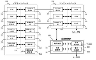
図4は、画像形成装置1の制御ブロックの全体構成を示すブロック図であり、ビデオコントローラ部200と、エンジンコントローラ部250に大別される。
<Control block diagram>
FIG. 4 is a block diagram showing the overall configuration of the control block of the
ビデオコントローラ部200において、CPU201はビデオコントローラ部200を構成する各部に指示を行なうCPU(中央演算処理装置)であり、ROM202は起動プログラムを格納するブートROM(読取専用メモリ)であり、不揮発性記憶部206はビデオコントローラ部200の制御プログラムおよび入力画像データ等を格納するハードディスクドライブであり、RAM203はビデオコントローラ部200の制御プログラムの作業用データを格納するランダムアクセスメモリである。
In the
ネットワークIF部207は、外部コンピュータ(不図示)との間で画像データの受け渡しを行なうLANカードであり、オプションIF部208は、原稿画像読取装置(不図示)やFAX回線(不図示)との間で画像データの受け渡しを行なうためのインタフェースであり、原稿画像読取装置と接続されるラティスコネクタ、公衆回線と接続されるモデム等から構成される。なお、本実施例における画像データの解像度は1200dpiであるとする。
The network IF
ネットワークIF部207やオプションIF部208を介して入力された画像データは、画像圧縮伸張部209にてデータの圧縮を施して不揮発性記憶部206に格納する。この際、画像データがネットワークIFを介して入力されたページ記述言語(PDL:Page Discription Languate)である場合には、ラスターイメージプロセッサとしてのRIP部210にて、PDLコードをラスターイメージデータに展開を行なった上で、圧縮を施す。
The image data input via the network IF
画像処理部204では、入力された画像データに対して、画像形成装置の特性に合わせた画像処理を施す。
The
画素カウント部211は、入力された画像データに対して、Y、M、C、Kの色成分毎に各色の画像データを構成する各画素の濃度値を積算する(以下ではこの値を画素値と呼ぶ)。本実施例では、各画素の濃度値は8bit(0〜255)の階調を有する。一例として、Yの画像データの1画素目濃度値が100で、2画素目の濃度値が50であれば、1画素目と2画素目の画素値は150となる。このような画素値の積算を、既定の領域内の全ての画素に対して、全ての色成分について行う。画素カウント部211にて算出された画素値は画素カウント部211内部のレジスタ(不図示)に記憶されており、画素カウント部211では規定の領域の画素のカウントを終えるとCPU201に割込み信号を送出する。
The
コントローラ部200では、割込み信号をトリガとして、制御プログラムに基づきCPU201がこのレジスタを読み出すことで、その時点での画素値を取得することができる。また、画素カウント部211により取得された画素値をもとに演算部212で画素値の差分計算などの演算を行う。上記画素値、演算結果を各記録材毎に演算結果記憶部213へ一時的に記憶しておき、制御プログラムに基づいてCPU201が読み出し、必要に応じて記憶されている演算結果を制御適用する。
In the
ビデオコントローラ部200では、制御プログラムに基づくCPU201の指示に従い、画像形成装置本体の動作と同期して、不揮発性記憶部206に記憶された画像データを読出して圧縮伸張部209による伸張を行ない、画像処理部204による画像処理と画素カウント部211による画素カウントを行った後に、エンジンコントローラ部250のPWM出力部254へ画像信号を送出する。
The
エンジンコントローラ部250において、CPU251はエンジンコントローラ部250を構成する各部に指示を行なうCPU(中央演算処理装置)であり、ROM252は制御プログラムとしてのファームウェアを格納するROM(読取専用メモリ)であり、RAM253はエンジンコントローラ部250の制御プログラムの作業用データを格納するランダムアクセスメモリである。
In the
PWM出力部254は、ビデオコントローラ部200の画像処理部204と接続されており、画像処理部204から送出される画像信号に基づいてPWM(Pulse Width Modulation)信号を生成する。
The
I/O部256は、画像形成装置1に備わる各種のアクチュエータおよびセンサ(不図示)と接続され、エンジンコントローラ部250では制御プログラムに基づくCPU251の指示に従い、画像形成装置1の各部を駆動して電子写真プロセス方式による印刷を行なう。前述の加圧力を制御するモーターM2や定着回転速度を制御する為のモーターM1もI/O部256に接続されている。
The I /
ビデオコントローラ部200とエンジンコントローラ部250は、それぞれ三線式のシリアル通信IF205、255を備えており、CPU201とCPU251はこれを介してデータの送受信を行なう。
The
ビデオコントローラ部200からエンジンコントローラ部250に対しては、主に入力された画像データのサイズや解像度、使用する記録材の種類(普通紙や厚紙等)、画素値といった、プリントジョブに関する情報の通知が行われる。
Notification of information related to the print job, such as the size and resolution of mainly input image data, the type of recording material used (plain paper, thick paper, etc.), and pixel values, from the
また、エンジンコントローラ部250は通知された情報に基づき、定着制御部350の制御回路部92においてサーミスタ630から入力する検知温度が所定の目標温度(定着温度)に維持されるように電力制御部352からヒータ600に入力する電力を制御している。
Further, based on the notified information, the
<領域分割と画素カウント>
本実施例における画素カウントの方法について、図5を用いて詳しく説明する。
<Region division and pixel count>
The pixel counting method in this embodiment will be described in detail with reference to FIG.
図5において斜線部は印刷可能な画像領域を示しており、搬送方向に直行する方向を主走査方向、搬送方向と平行な方向を副走査方向と呼んでいる。本実施例では、画像領域のどのあたりにどの程度の濃度のトナー像が形成されているかというトナー量分布を知る必要があるため、画像領域を主走査方向に複数の領域に分割し、領域ごとに画素値をカウントする。画素値が大きいということは、すなわち、その領域のトナー量が多いことを示す。 In FIG. 5, the shaded area indicates a printable image area, and the direction perpendicular to the transport direction is called the main scanning direction, and the direction parallel to the transport direction is called the sub-scanning direction. In this embodiment, since it is necessary to know the toner amount distribution of which part of the image region and what density of the toner image is formed, the image region is divided into a plurality of regions in the main scanning direction, and each region is divided. The pixel value is counted in. A large pixel value indicates that the amount of toner in the region is large.
画像領域の主走査方向の幅は、画像形成装置100が印刷可能な画像の最大幅と等しく、本実施例の場合は330mmとなっている。また、本実施例における画像データは1200dpiであるので、主走査方向の画素数は15600画素となる。これを、X0〜X9で示す10の領域に分割することとした。すなわち、主走査方向の1領域の幅は1560画素である。 The width of the image region in the main scanning direction is equal to the maximum width of the image that can be printed by the image forming apparatus 100, and is 330 mm in the case of this embodiment. Further, since the image data in this embodiment is 1200 dpi, the number of pixels in the main scanning direction is 15600 pixels. It was decided to divide this into 10 regions represented by X0 to X9. That is, the width of one region in the main scanning direction is 1560 pixels.
次に副走査方向については、1つの領域の幅を4160画素とし、記録材がおさまるだけの領域を用意することとした。領域数が可変であるため、図中ではY0〜Ynという領域名で示している。 Next, regarding the sub-scanning direction, the width of one area is set to 4160 pixels, and an area where the recording material can be accommodated is prepared. Since the number of regions is variable, they are indicated by region names Y0 to Yn in the figure.
以上のように画像領域は主走査方向と副走査方向とでそれぞれ領域分割され、領域ごとに画素値を算出する。各領域はX0Y0〜X9Ynのように、主走査方向と副走査方向のそれぞれの領域名を組み合わせて判別される。 As described above, the image area is divided into areas in the main scanning direction and the sub-scanning direction, respectively, and the pixel value is calculated for each area. Each area is determined by combining the names of the respective areas in the main scanning direction and the sub-scanning direction, such as X0Y0 to X9Yn.
領域分割の例を図6に示す。図6は記録材としてA3サイズを用いた場合の例であり、Pが記録材を示している。 An example of region division is shown in FIG. FIG. 6 is an example when A3 size is used as the recording material, and P indicates the recording material.
主走査方向についてはX0〜X9の10領域に分割される。一方、副走査方向についてはA3サイズの長さが420mm=19842画素であるため、Y0〜Y4の5領域でおさまることになる。X0Y0〜X9Y4の50領域に分割されることとなる。 The main scanning direction is divided into 10 regions X0 to X9. On the other hand, in the sub-scanning direction, since the length of the A3 size is 420 mm = 19842 pixels, it can be accommodated in the five regions Y0 to Y4. It will be divided into 50 areas of X0Y0 to X9Y4.
なお主走査方向の領域分割の数はこれに限るものではなく、求められるトナー量分布の精度に応じて分割数を変えても良い。また、副走査方向の領域幅や分割方法もこれに限るものではなく、領域数をあらかじめ決めておき、印刷する画像の長さを領域の数で等分する方法などでもよい。 The number of region divisions in the main scanning direction is not limited to this, and the number of divisions may be changed according to the required accuracy of the toner amount distribution. Further, the area width in the sub-scanning direction and the division method are not limited to this, and a method in which the number of areas is determined in advance and the length of the image to be printed is equally divided by the number of areas may be used.
画素カウントの例を図7に示す。図7において、PはA3サイズ用紙に印刷する画像の例であり、下側の表は各領域の画素値の例を示している。なお、画素値が0の領域については記載を省略している。 An example of pixel counting is shown in FIG. In FIG. 7, P is an example of an image to be printed on A3 size paper, and the lower table shows an example of pixel values in each region. The description of the region where the pixel value is 0 is omitted.
領域X1Y3やX2Y3はトナー量の多い図形が形成されるため、画素値が大きくなっている。領域X1Y2、X7Y0、X7Y1には文字のみの画像が形成されるため、画素値は小さい値となっている。それ以外の領域にはトナー像は形成されないため、画素値は0となっている。 In the regions X1Y3 and X2Y3, a figure having a large amount of toner is formed, so that the pixel value is large. Since an image containing only characters is formed in the regions X1Y2, X7Y0, and X7Y1, the pixel value is small. Since the toner image is not formed in the other regions, the pixel value is 0.
<画素値に応じた二面目温調温度決定方法>
次に両面印刷ジョブにおける二面目の温調温度設定を画素値に応じて決定する方法について説明する。
<Method for determining the temperature control for the second surface according to the pixel value>
Next, a method of determining the temperature control temperature setting of the second side in the double-sided printing job according to the pixel value will be described.
まず、一面目の定着処理を行う際、一面目に形成された未定着トナー像を上記画素カウントの方法に則ってX0Y0〜X9Ynの各画素値をカウントし、上記演算結果記憶部213に保存する。
First, when performing the fixing process on the first surface, the unfixed toner image formed on the first surface is counted for each pixel value of X0Y0 to X9Yn according to the pixel counting method, and stored in the calculation
続いて、二面目に画像を形成する際、一面目同様X0Y0〜X9Ynの各画素値をカウントする。二面目を定着処理する為の温調温度設定は、二面目にトナーが最大量転写されている領域があるものとして設定されているX2℃をデフォルト値として、二面目のX0Y0〜X9Ynの各領域毎の画素カウント値を考慮した減算値αと一面目のX0Y0〜X9Ynの各領域毎の画素カウント値を考慮した減算値βを用いて、各領域毎に必要温調温度X2−α−β℃を演算し、各領域毎に求めまった必要温調温度の中で最も高い値を採用し設定する。但し、各領域において二面目の画素カウント値が0だった場合、該領域は温調温度採用候補から除外する。 Subsequently, when forming an image on the second surface, each pixel value of X0Y0 to X9Yn is counted as in the case of the first surface. The temperature control temperature setting for fixing the second surface is set to the default value of X2 ° C, which is set as having a region where the maximum amount of toner is transferred on the second surface, and each region of X0Y0 to X9Yn on the second surface. The required temperature control temperature X2-α-β ° C. is used for each region by using the subtraction value α considering the pixel count value for each region and the subtraction value β considering the pixel count value for each region of X0Y0 to X9Yn on the first surface. Is calculated, and the highest value among the required temperature control temperatures obtained for each region is adopted and set. However, if the pixel count value on the second surface is 0 in each region, that region is excluded from the temperature control temperature adoption candidates.
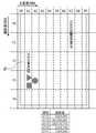
図8は上記二面目温調温度決定方法の具体例を示している。記録材は坪量80gsmのオフィス紙でサイズはA3とした。本ケースにおける減算値α、βは図8の表(b)の通りである。また、上記X2℃に関しては本ケースの場合180℃であった。上記各領域の画素値のカウントと必要温調温度演算の結果は図8の表(a)のようになり、必要温調温度が最も高くなる領域はX6Y3(もしくは同値でX7Y3)となる事が分かる。よって、本ケースにおける二面目温調温度は174℃となり、本来必要だった温調温度より低温での定着処理が可能となった。 FIG. 8 shows a specific example of the method for determining the temperature control on the second surface. The recording material was office paper with a basis weight of 80 gsm and the size was A3. The subtraction values α and β in this case are as shown in Table (b) of FIG. The temperature of X2 ° C. was 180 ° C. in this case. The count of the pixel values in each of the above regions and the result of the required temperature control temperature calculation are as shown in Table (a) of FIG. 8, and the region where the required temperature control temperature is the highest may be X6Y3 (or X7Y3 with the same value). I understand. Therefore, the temperature control temperature of the second surface in this case is 174 ° C., and the fixing process can be performed at a temperature lower than the originally required temperature control temperature.
<シーケンス>
上記の制御を実現するためにエンジンコントローラ部のCPU251が実行する処理を図9のフローチャートに示す。
<Sequence>
The flowchart of FIG. 9 shows the process executed by the
プリントジョブが開始されると、CPU251は記録材の紙種や坪量に応じて一面目デフォルト温調温度X1℃を決定する(S101)。使用する記録材の種類や坪量はプリントジョブの開始時にビデオコントローラ部200からシリアル通信IF205、255を通じてエンジンコントローラ部に通知される。
When the print job is started, the
次にS102へと進み、CPU251は画像領域の各領域の画素値を取得する。すなわち、図6で示した例のようにX0Y0〜X9Ynの各領域の画素値を取得する。画素カウント部211でカウントされた各領域の画素値vは、一面目ジョブの場合はv1、二面目ジョブの場合はv2とし、ビデオコントローラ部200からシリアル通信IF205、255を通じてエンジンコントローラ部に通知されるため、CPU251はその情報をRAM253に保存する。
Next, the process proceeds to S102, and the
その際、一面目ジョブだった場合、上記でカウントした各領域の画素値v1を演算結果記憶部213へも保存する(S104)。 At that time, in the case of the first-side job, the pixel value v1 of each area counted above is also saved in the calculation result storage unit 213 (S104).
続いて、CPU251は取得した各領域の画素値v1を参照し、その中で最大のv1を探索し、最大値V1を決定する。V1に該当する減算値αを図9の表1から選択し(S105)、温調温度T1をX1−α℃へ変更する。変更された温調温度X1−α℃は定着制御部350に通知され、それに応じた温調温度に温度センサTHが制御されるよう電源装置91からヒータ600に入力する電力を制御し定着処理を行う(S106)。
Subsequently, the
二面目のジョブが存在しない場合は、演算結果記憶部213へ保存したv1を消去し(S115)プリントジョブを終了する。二面目ジョブへ移行する場合は、温調温度を画像情報が通知されるまでの間の待機温度である待機中温調温度へ変更する(S108)。画像情報が通知されたら、二面目デフォルト温調温度X2℃へ変更する(S109)。X2℃はX1℃より低い温度である。
If the job on the second side does not exist, v1 saved in the calculation
次に、一面目と同様に二面目画像におけるX0Y0〜X9Ynの各領域の画素値v2を取得する(S110)。この時、CPU251は演算記憶部213へ保存しておいた一面目時の各領域画素値v1を読み出して取得し(S111)、各領域毎に、画素値v2から図9の表1の該当する減算値αを選択し、また、画素値v1に該当する減算値βを選択し、各領域毎のX2−α―β℃を演算する(S112)。
Next, the pixel values v2 of each region of X0Y0 to X9Yn in the second surface image are acquired in the same manner as on the first surface (S110). At this time, the
各領域毎に演算した値から最大値を抽出し、その値を二面目温調温度T2として設定して定着処理を実行する(S113、S114)。 The maximum value is extracted from the value calculated for each region, the value is set as the second surface temperature control temperature T2, and the fixing process is executed (S113, S114).
二面目ジョブの定着処理が終了したら、演算結果記憶部213へ保存したv1を消去し(S115)プリントジョブを終了する。
When the fixing process of the second-side job is completed, v1 saved in the calculation
上記シーケンスに関して、例えば80sgmオフィス紙A3サイズに適用すると、本実施例ではX1=190℃、X2=180℃、待機中温調温度=160℃であり、減算値α、βは図9の表1の通りである。これらの値は限定されるものでは無く、記録材の種類、坪量、紙サイズによって異なるし、定着装置構成によっても異なる。 When the above sequence is applied to, for example, 80 sgm office paper A3 size, in this embodiment, X1 = 190 ° C., X2 = 180 ° C., standby temperature control temperature = 160 ° C., and the subtraction values α and β are shown in Table 1 of FIG. It's a street. These values are not limited, and vary depending on the type of recording material, basis weight, paper size, and also on the fixing device configuration.
また、画素値と減算値α、βの関係に関して、画素値の区切りはもっと細かくても良いし、関数として設定されていても良い。 Further, regarding the relationship between the pixel value and the subtraction values α and β, the division of the pixel value may be finer or may be set as a function.
以上、本実施形態により、両面印刷ジョブの一面目/二面目の記録材へのトナー転写状態を考慮する事で、二面目の定着温調温度を可能な限り低温にして定着処理を実行する事が可能となり、定着不良を回避しつつ省エネルギー化を達成することができる。 As described above, according to the present embodiment, by considering the toner transfer state to the recording material on the first and second sides of the double-sided printing job, the fixing temperature control temperature on the second side is set to be as low as possible and the fixing process is executed. It is possible to achieve energy saving while avoiding poor fixing.
前述した実施例1では二面目ジョブの際、待機中温調温度から必要最小限の定着可能温度へ温度変更する動作に関して記述した。本実施例では定着回転速度を制御する事で同様の効果の実現を目指す。この場合、温調温度の更なる減算が可能であり、省エネルギー化を見込める。 In Example 1 described above, the operation of changing the temperature from the standby temperature control temperature to the minimum necessary fixable temperature during the second-side job is described. In this embodiment, the same effect is achieved by controlling the fixing rotation speed. In this case, the temperature control temperature can be further subtracted, and energy saving can be expected.
なお、実施例1と同様の構成については同符号をつけて、説明を割愛する。 The same components as those in the first embodiment are designated by the same reference numerals, and the description thereof will be omitted.
<シーケンス>
上記の制御を実現するためにエンジンコントローラ部のCPU251が実行する処理を図10のフローチャートに示す。
<Sequence>
The flowchart of FIG. 10 shows the process executed by the
プリントジョブが開始されると、CPU251は記録材の紙種や坪量に応じて一面目デフォルト温調温度X1℃、デフォルト定着回転速度Rmm/sを決定する(S101)。使用する記録材の種類や坪量はプリントジョブの開始時にビデオコントローラ部200からシリアル通信IF205、255を通じてエンジンコントローラ部に通知される。
When the print job is started, the
次にS102へと進み、CPU251は画像領域の各領域の画素値を取得する。すなわち、図6で示した例のようにX0Y0〜X9Ynの各領域の画素値を取得する。画素カウント部211でカウントされた各領域の画素値vは、一面目ジョブの場合はv1、二面目ジョブの場合はv2とし、ビデオコントローラ部200からシリアル通信IF205、255を通じてエンジンコントローラ部に通知されるため、CPU251はその情報をRAM253に保存する。その際、一面目ジョブだった場合、上記でカウントした各領域の画素値v1を演算結果記憶部213へも保存する(S104)。
Next, the process proceeds to S102, and the
続いて、CPU251は取得した各領域の画素値v1を参照し、その中で最大のv1を探索し、最大値V1を決定する。V1に該当する減速係数αを図10の表1から選択し(S105)、定着回転速度PS1をR×αmm/sへ変更する。変更された回転速度R×αmm/sはエンジンコントローラ250のCPU251に通知され、それに応じた回転速度に制御されるようI/O部256からモーターM1を制御し定着処理を行う(S106)。
Subsequently, the
二面目のジョブが存在しない場合は、演算結果記憶部213へ保存したv1を消去し、回転速度をRに戻して(S115)プリントジョブを終了する。二面目ジョブへ移行する場合は、回転速度をRへ戻して、温調温度を画像情報が通知されるまでの間の待機温度である待機中温調温度へ変更する(S108)。
If the job on the second side does not exist, v1 saved in the calculation
画像情報が通知されたら、一面目と同様に二面目画像におけるX0Y0〜X9Ynの各領域の画素値v2を取得する(S109)。この時、CPU251は演算記憶部213へ保存しておいた一面目時の各領域画素値v1を読み出して取得し(S110)、各領域毎に、画素値v2から図10の表1の該当する減速係数αを選択し、また、画素値v1に該当する減速係数βを選択し、各領域毎のR×α×βmm/sを演算する(S111)。各領域毎に演算した値から最小値を抽出し、その値を二面目回転速度PS2として設定して定着処理を実行する(S112、S113)。
When the image information is notified, the pixel value v2 of each region of X0Y0 to X9Yn in the second side image is acquired in the same manner as in the first side image (S109). At this time, the
二面目ジョブの定着処理が終了したら、演算結果記憶部213へ保存したv1を消去し、回転速度をRへ戻し(S115)プリントジョブを終了する。
When the fixing process of the second-side job is completed, v1 saved in the calculation
上記シーケンスに関して実施例1同様、80sgmオフィス紙A3サイズに適用した。本実施例ではX1=190℃、待機中温調温度=160℃であり、R=200mm/sであり、減速係数α、βは図10の表1の通りである。これらの値は限定されるものでは無く、記録材の種類、坪量、紙サイズによって異なるし、定着装置構成によっても異なる。 The above sequence was applied to 80 sgm office paper A3 size as in Example 1. In this embodiment, X1 = 190 ° C., standby temperature control temperature = 160 ° C., R = 200 mm / s, and the deceleration coefficients α and β are as shown in Table 1 of FIG. These values are not limited, and vary depending on the type of recording material, basis weight, paper size, and also on the fixing device configuration.
また、画素値と減速係数α、βの関係に関して、画素値の区切りはもっと細かくても良いし、関数として設定されていても良い。 Further, regarding the relationship between the pixel value and the deceleration coefficients α and β, the division of the pixel value may be finer or may be set as a function.
以上、本実施形態により、両面印刷ジョブの一面目/二面目の記録材へのトナー転写状態を考慮した結果を定着回転速度へフィードバックする事で必要量定着回転速度を減速し、定着処理実行時間を増加させる事で、定着温調温度を可能な限り低温にして定着処理を実行する事が可能となり、定着不良を回避しつつ省エネルギー化を達成することができる。 As described above, according to the present embodiment, the required amount of fixing rotation speed is reduced by feeding back the result of considering the toner transfer state to the recording material on the first and second sides of the double-sided printing job to the fixing rotation speed, and the fixing process execution time. By increasing the number of sheets, it is possible to set the fixing temperature control temperature as low as possible to execute the fixing process, and it is possible to achieve energy saving while avoiding fixing defects.
前述した実施例2では二面目ジョブの際、待機中温調温度のまま定着回転速度を制御する事で定着不良を回避しつつ省エネルギー化を達成した。 In the second embodiment described above, energy saving was achieved while avoiding fixing defects by controlling the fixing rotation speed while maintaining the standby temperature control temperature during the second-side job.
しかしながら、例えば両面印刷の連続ジョブ等、状況によっては定着回転速度を減速する事による生産性低下の可能性を孕む。 However, depending on the situation, for example, continuous jobs for double-sided printing, there is a possibility that productivity may decrease due to slowing down the fixing rotation speed.
よって、本実施例では二面目ジョブの際、待機中温調温度のまま定着回転速度を変更せず定着不良を回避する施策として、加圧力アップによるニップ部Nの幅の増加を実施し同様の効果の実現を目指す。この場合、生産性の低下を防ぎ且つ、省エネルギー化が見込める。
なお、実施例1と同様の構成については同符号をつけて、説明を割愛する。
Therefore, in this embodiment, in the case of the second-side job, as a measure to avoid the fixing failure without changing the fixing rotation speed while keeping the standby temperature control temperature, the width of the nip portion N is increased by increasing the pressing force, and the same effect is obtained. Aim to realize. In this case, it is possible to prevent a decrease in productivity and save energy.
The same components as those in the first embodiment are designated by the same reference numerals, and the description thereof will be omitted.
<シーケンス>
上記の制御を実現するためにエンジンコントローラ部のCPU251が実行する処理を図11のフローチャートに示す。
<Sequence>
The flowchart of FIG. 11 shows the process executed by the
プリントジョブが開始されると、CPU251は記録材の紙種や坪量に応じて一面目デフォルト温調温度X1℃、デフォルト加圧力FNを決定する(S101)。使用する記録材の種類や坪量はプリントジョブの開始時にビデオコントローラ部200からシリアル通信IF205、255を通じてエンジンコントローラ部に通知される。
When the print job is started, the
次にS102へと進み、CPU251は画像領域の各領域の画素値を取得する。すなわち、図6で示した例のようにX0Y0〜X9Ynの各領域の画素値を取得する。画素カウント部211でカウントされた各領域の画素値vは、一面目ジョブの場合はv1、二面目ジョブの場合はv2とし、ビデオコントローラ部200からシリアル通信IF205、255を通じてエンジンコントローラ部に通知されるため、CPU251はその情報をRAM253に保存する。
Next, the process proceeds to S102, and the
その際、一面目ジョブだった場合、上記でカウントした各領域の画素値v1を演算結果記憶部213へも保存する(S104)。 At that time, in the case of the first-side job, the pixel value v1 of each area counted above is also saved in the calculation result storage unit 213 (S104).
続いて、CPU251は取得した各領域の画素値v1を参照し、その中で最大のv1を探索し、最大値V1を決定する。V1に該当する加圧力加算値αを図11の表1から選択し(S105)、加圧力K1をF+αNへ変更する。変更された加圧力F+αNはエンジンコントローラ250のCPU251に通知され、それに応じた加圧力に制御されるようI/O部256からモータM2を制御し定着処理を行う(S106)。
Subsequently, the
二面目のジョブが存在しない場合は、演算結果記憶部213へ保存したv1を消去し、加圧力をFに戻して(S115)プリントジョブを終了する。二面目ジョブへ移行する場合は、加圧力をFに戻して、温調温度を画像情報が通知されるまでの間の待機温度である待機中温調温度へ変更する(S108)。
If the job on the second side does not exist, v1 saved in the calculation
画像情報が通知されたら、一面目と同様に二面目画像におけるX0Y0〜X9Ynの各領域の画素値v2を取得する(S109)。この時、CPU251は演算記憶部213へ保存しておいた一面目時の各領域画素値v1を読み出して取得し(S110)、各領域毎に、画素値v2から図11の表1の該当する加圧力加算値αを選択し、また、画素値v1に該当する加圧力加算値βを選択し、各領域毎のF+α+βNを演算する(S111)。各領域毎に演算した値から最大値を抽出し、その値を二面目加圧力K2として設定して定着処理を実行する(S112、S113)。
When the image information is notified, the pixel value v2 of each region of X0Y0 to X9Yn in the second side image is acquired in the same manner as in the first side image (S109). At this time, the
二面目ジョブの定着処理が終了したら、演算結果記憶部213へ保存したv1を消去し、加圧力をFへ戻し(S115)プリントジョブを終了する。
When the fixing process of the second-side job is completed, v1 stored in the calculation
上記シーケンスに関して実施例1同様、80sgmオフィス紙A3サイズに適用した。本実施例ではX1=190℃、待機中温調温度=160℃であり、F=313.6Nであり、加圧力加算値α、βは図11の表1の通りである。これらの値は限定されるものでは無く、記録材の種類、坪量、紙サイズによって異なるし、定着装置構成によっても異なる。
また、画素値と加圧力加算値α、βの関係に関して、画素値の区切りはもっと細かくても良いし、関数として設定されていても良い。
The above sequence was applied to 80 sgm office paper A3 size as in Example 1. In this embodiment, X1 = 190 ° C., standby temperature control temperature = 160 ° C., F = 313.6N, and the pressure addition values α and β are as shown in Table 1 of FIG. These values are not limited, and vary depending on the type of recording material, basis weight, paper size, and also on the fixing device configuration.
Further, regarding the relationship between the pixel value and the pressure addition values α and β, the division of the pixel values may be finer or may be set as a function.
以上、本実施形態により、両面印刷ジョブの一面目/二面目の記録材へのトナー転写状態を考慮した結果を定着加圧力へフィードバックする。それによって必要量加圧力を増加させる事で、定着ニップ部を広げ、定着処理実行時間を増加させる事ができ、定着温調温度を可能な限り低温にして定着処理を実行する事が可能となり、定着不良を回避しつつ省エネルギー化を達成することができる。 As described above, according to the present embodiment, the result of considering the toner transfer state to the recording material on the first and second sides of the double-sided printing job is fed back to the fixing pressing force. By increasing the required amount of pressure, the fixing nip part can be expanded and the fixing process execution time can be increased, and the fixing temperature control temperature can be set as low as possible to execute the fixing process. Energy saving can be achieved while avoiding poor fixing.
1 画像形成装置、3 画像プロセス部、603 定着ベルト、
700 加圧ローラ、200 ビデオコントローラ、
250 エンジンコントローラ、630 温度検知素子、P 記録材
1 image forming device, 3 image process section, 603 fixing belt,
700 pressure roller, 200 video controller,
250 engine controller, 630 temperature detection element, P recording material
Claims (3)
無端状の定着ベルトと、前記定着ベルトの内側に配設されたヒータと、前記定着ベルトと圧接してニップ部を形成する加圧部材とから構成され、前記ニップ部で未定着トナー像を担持した記録材を搬送しながら加熱し、前記未定着トナー像を記録材に定着する定着部と、
前記ヒータあるいは前記加圧部材の温度を検知する1つあるいは複数個の温度検知部と、
前記ヒータの温度を制御する温度制御部と、
記録材の搬送方向に交差する幅方向と前記搬送方向に平行な方向それぞれに分割された複数の分割領域毎に、前記記録材の第一面に形成する未定着トナー像の濃度に関する情報と、前記第一面と反対側の第二面に形成する未定着トナー像の濃度に関する情報を取得する情報取得部と、
記録材の両面に画像を形成する両面印刷機構と、
を備えた画像形成装置において、
前記ヒータは、前記幅方向において前記ニップ部を通過する最大サイズの記録材の通過領域全域に亘って前記定着ベルトを加熱する少なくとも1つの発熱体を有し、
前記分割領域毎に、前記第二面に最大濃度で未定着トナー像を形成した場合に当該未定着トナー像の定着に必要な予め決められた温度と、前記第一面に形成された未定着トナー像の濃度に応じて決まる第一温度と、前記第二面に形成された未定着トナー像の濃度に応じて決まる第二温度とに基づいて、前記分割領域の両面濃度に応じた定着温度を求め、前記分割領域毎に求めた定着温度のうち最も高い定着温度を、前記第二面に形成された未定着トナー像を記録材に定着する際の前記ヒータの目標温度に設定する制御部を備える、
ことを特徴とする画像形成装置。 An image forming part that forms an unfixed toner image on the recording material,
It is composed of an endless fixing belt, a heater disposed inside the fixing belt, and a pressurizing member that press-contacts with the fixing belt to form a nip portion, and carries an unfixed toner image on the nip portion. A fixing portion for fixing the unfixed toner image to the recording material by heating while transporting the recording material.
Said heater or said one sensing the temperature of the pressure member or a plurality of temperature sensing portion,
A temperature control unit that controls the temperature of the heater,
Information on the concentration of the unfixed toner image formed on the first surface of the recording material for each of the plurality of divided regions divided in the width direction intersecting the transport direction of the recording material and the direction parallel to the transport direction. and information acquisition unit get information on the concentration of the unfixed toner image formed on the second surface opposite to the first surface,
A duplex printing mechanism for forming images on both sides of the record member,
In an image forming apparatus equipped with
The heater has at least one heating element that heats the anchoring belt over the entire passage area of the largest size recording material passing through the nip in the width direction.
For each of the divided regions, a predetermined temperature required for fixing the unfixed toner image when the unfixed toner image is formed on the second surface at the maximum concentration, and the unfixed unfixed formed on the first surface. A fixing temperature according to the double-sided density of the divided region based on a first temperature determined by the density of the toner image and a second temperature determined by the density of the unfixed toner image formed on the second surface. look, the highest fixing temperature of the fixing temperature obtained in each divided region, before Symbol control for setting the target temperature of the heater at the time of fixing on the recording material an unfixed toner image formed on the second surface Equipped with a part
An image forming apparatus characterized in that.
無端状の定着ベルトと、前記定着ベルトの内側に配設されたヒータと、前記定着ベルトと圧接してニップ部を形成する加圧部材とから構成され、前記ニップ部で未定着トナー像を担持した記録材を搬送しながら加熱し、前記未定着トナー像を記録材に定着する定着部と、It is composed of an endless fixing belt, a heater disposed inside the fixing belt, and a pressurizing member that press-contacts with the fixing belt to form a nip portion, and carries an unfixed toner image on the nip portion. A fixing portion for fixing the unfixed toner image to the recording material by heating while transporting the recording material.
前記ヒータあるいは前記加圧部材の温度を検知する1つあるいは複数個の温度検知部と、One or more temperature detectors that detect the temperature of the heater or the pressurizing member, and
前記定着ベルトの回転速度を変更する記録材搬送速度可変機構と、A recording material transfer speed variable mechanism that changes the rotation speed of the fixing belt, and
記録材の搬送方向に交差する幅方向と前記搬送方向に平行な方向それぞれに分割された複数の分割領域毎に、前記記録材の第一面に形成する未定着トナー像の濃度に関する情報と、前記第一面と反対側の第二面に形成する未定着トナー像の濃度に関する情報を取得する情報取得部と、Information on the concentration of the unfixed toner image formed on the first surface of the recording material for each of the plurality of divided regions divided in the width direction intersecting the transport direction of the recording material and the direction parallel to the transport direction. An information acquisition unit that acquires information on the density of the unfixed toner image formed on the second surface opposite to the first surface, and
記録材の両面に画像を形成する両面印刷機構と、A double-sided printing mechanism that forms images on both sides of the recording material,
を備えた画像形成装置において、In an image forming apparatus equipped with
前記ヒータは、前記幅方向において前記ニップ部を通過する最大サイズの記録材の通過領域全域に亘って前記定着ベルトを加熱する少なくとも1つの発熱体を有し、The heater has at least one heating element that heats the anchoring belt over the entire passage area of the largest size recording material passing through the nip in the width direction.
前記分割領域毎に、記録材の坪量に応じて予め決められた回転速度と、前記第一面に形成された未定着トナー像の濃度に応じて決まる第一減速値と、前記第二面に形成された未定着トナー像の濃度に応じて決まる第二減速値とに基づいて、前記分割領域の両面濃度に応じた定着速度を求め、前記分割領域毎に求めた定着速度のうち最も遅い定着速度を、前記第二面に形成された未定着トナー像を記録材に定着する際の前記定着ベルトの回転速度に設定する制御部を備える、For each of the divided regions, a rotation speed determined in advance according to the basis weight of the recording material, a first deceleration value determined according to the density of the unfixed toner image formed on the first surface, and the second surface. Based on the second deceleration value determined according to the density of the unfixed toner image formed in, the fixing speed according to the double-sided density of the divided region is obtained, and the fixing speed is the slowest among the fixing speeds obtained for each divided region. A control unit for setting the fixing speed to the rotation speed of the fixing belt when the unfixed toner image formed on the second surface is fixed to the recording material is provided.
ことを特徴とする画像形成装置。An image forming apparatus characterized in that.
無端状の定着ベルトと、前記定着ベルトの内側に配設されたヒータと、前記定着ベルトと圧接してニップ部を形成する加圧部材とから構成され、前記ニップ部で未定着トナー像を担持した記録材を搬送しながら加熱し、前記未定着トナー像を記録材に定着する定着部と、It is composed of an endless fixing belt, a heater disposed inside the fixing belt, and a pressurizing member that press-contacts with the fixing belt to form a nip portion, and carries an unfixed toner image on the nip portion. A fixing portion for fixing the unfixed toner image to the recording material by heating while transporting the recording material.
前記ヒータあるいは前記加圧部材の温度を検知する1つあるいは複数個の温度検知部と、One or more temperature detectors that detect the temperature of the heater or the pressurizing member, and
前記加圧部材の加圧力を変更する加圧力可変機構と、A pressure variable mechanism that changes the pressure of the pressure member,
記録材の搬送方向に交差する幅方向と前記搬送方向に平行な方向それぞれに分割された複数の分割領域毎に、前記記録材の第一面に形成する未定着トナー像の濃度に関する情報と、前記第一面と反対側の第二面に形成する未定着トナー像の濃度に関する情報を取得する情報取得部と、Information on the concentration of the unfixed toner image formed on the first surface of the recording material for each of the plurality of divided regions divided in the width direction intersecting the transport direction of the recording material and the direction parallel to the transport direction. An information acquisition unit that acquires information on the density of the unfixed toner image formed on the second surface opposite to the first surface, and
記録材の両面に画像を形成する両面印刷機構と、A double-sided printing mechanism that forms images on both sides of the recording material,
を備えた画像形成装置において、In an image forming apparatus equipped with
前記ヒータは、前記幅方向において前記ニップ部を通過する最大サイズの記録材の通過領域全域に亘って前記定着ベルトを加熱する少なくとも1つの発熱体を有し、The heater has at least one heating element that heats the anchoring belt over the entire passage area of the largest size recording material passing through the nip in the width direction.
前記分割領域毎に、記録材の坪量に応じて予め決められた加圧力と、前記第一面に形成された未定着トナー像の濃度に応じて決まる第一加圧力と、前記第二面に形成された未定着トナー像の濃度に応じて決まる第二加圧力とに基づいて、前記分割領域の両面濃度に応じた定着加圧力を求め、前記分割領域毎に求めた定着加圧力のうち最も大きい定着加圧力を、前記第二面に形成された未定着トナー像を記録材に定着する際の前記加圧部材の加圧力に設定する制御部を備える、For each of the divided regions, a predetermined pressing force according to the basis weight of the recording material, a first pressing force determined according to the concentration of the unfixed toner image formed on the first surface, and the second surface. Based on the second pressing force determined according to the density of the unfixed toner image formed in, the fixing pressing force corresponding to the double-sided density of the divided region was obtained, and among the fixing pressing pressures obtained for each divided region. A control unit is provided which sets the maximum fixing pressing force to the pressing force of the pressurizing member when the unfixed toner image formed on the second surface is fixed to the recording material.
ことを特徴とする画像形成装置。An image forming apparatus characterized in that.
Priority Applications (1)
| Application Number | Priority Date | Filing Date | Title |
|---|---|---|---|
| JP2017145965A JP6980441B2 (en) | 2017-07-28 | 2017-07-28 | Image forming device |
Applications Claiming Priority (1)
| Application Number | Priority Date | Filing Date | Title |
|---|---|---|---|
| JP2017145965A JP6980441B2 (en) | 2017-07-28 | 2017-07-28 | Image forming device |
Publications (3)
| Publication Number | Publication Date |
|---|---|
| JP2019028180A JP2019028180A (en) | 2019-02-21 |
| JP2019028180A5 JP2019028180A5 (en) | 2020-10-01 |
| JP6980441B2 true JP6980441B2 (en) | 2021-12-15 |
Family
ID=65476157
Family Applications (1)
| Application Number | Title | Priority Date | Filing Date |
|---|---|---|---|
| JP2017145965A Active JP6980441B2 (en) | 2017-07-28 | 2017-07-28 | Image forming device |
Country Status (1)
| Country | Link |
|---|---|
| JP (1) | JP6980441B2 (en) |
Family Cites Families (3)
| Publication number | Priority date | Publication date | Assignee | Title |
|---|---|---|---|---|
| JP2014122932A (en) * | 2012-12-20 | 2014-07-03 | Fuji Xerox Co Ltd | Image forming apparatus and program |
| JP2014225004A (en) * | 2013-04-19 | 2014-12-04 | 株式会社リコー | Fixing apparatus and image forming apparatus |
| JP5954344B2 (en) * | 2014-02-13 | 2016-07-20 | コニカミノルタ株式会社 | Image forming apparatus |
-
2017
- 2017-07-28 JP JP2017145965A patent/JP6980441B2/en active Active
Also Published As
| Publication number | Publication date |
|---|---|
| JP2019028180A (en) | 2019-02-21 |
Similar Documents
| Publication | Publication Date | Title |
|---|---|---|
| US7437086B2 (en) | Image forming apparatus with change unit for changing temperature of fixing unit at time of actuating image forming unit | |
| JP5310613B2 (en) | Image processing apparatus and image processing apparatus control method | |
| JP6060940B2 (en) | Image forming apparatus | |
| JP2010002702A (en) | Image forming apparatus and image forming method | |
| JP2019138959A (en) | Image forming device | |
| JP4871633B2 (en) | Image forming apparatus | |
| JP2007101861A (en) | Fixing device | |
| US11237504B2 (en) | Image forming apparatus, image forming method, and computer-readable recording medium with program recorded therein | |
| JP4306557B2 (en) | Image forming system | |
| JP2006163017A (en) | Fixing device and image forming apparatus | |
| JP6980441B2 (en) | Image forming device | |
| US20110311255A1 (en) | Image forming apparatus and image forming method | |
| JP4972985B2 (en) | Image forming apparatus | |
| JP2013076878A (en) | Image forming apparatus | |
| JP4701051B2 (en) | Fixing apparatus and image forming apparatus | |
| JP7154854B2 (en) | Image forming apparatus and fixing device | |
| JP6095345B2 (en) | Image forming apparatus | |
| JP2017102340A (en) | Image forming apparatus | |
| JP2020118936A (en) | Image forming apparatus | |
| JP2019148724A (en) | Image forming device and image forming method | |
| JP2019028189A (en) | Image forming apparatus | |
| JP2008009004A (en) | Image forming device | |
| JP2019128476A (en) | Image forming apparatus and image heating device | |
| JP5439956B2 (en) | Image fixing apparatus and image forming apparatus | |
| JP2006194930A (en) | Fixing apparatus |
Legal Events
| Date | Code | Title | Description |
|---|---|---|---|
| RD03 | Notification of appointment of power of attorney |
Free format text: JAPANESE INTERMEDIATE CODE: A7423 Effective date: 20181108 |
|
| RD04 | Notification of resignation of power of attorney |
Free format text: JAPANESE INTERMEDIATE CODE: A7424 Effective date: 20181116 |
|
| RD02 | Notification of acceptance of power of attorney |
Free format text: JAPANESE INTERMEDIATE CODE: A7422 Effective date: 20200206 |
|
| RD04 | Notification of resignation of power of attorney |
Free format text: JAPANESE INTERMEDIATE CODE: A7424 Effective date: 20200207 |
|
| A521 | Written amendment |
Free format text: JAPANESE INTERMEDIATE CODE: A523 Effective date: 20200727 |
|
| A621 | Written request for application examination |
Free format text: JAPANESE INTERMEDIATE CODE: A621 Effective date: 20200727 |
|
| A977 | Report on retrieval |
Free format text: JAPANESE INTERMEDIATE CODE: A971007 Effective date: 20210526 |
|
| A131 | Notification of reasons for refusal |
Free format text: JAPANESE INTERMEDIATE CODE: A131 Effective date: 20210601 |
|
| A521 | Written amendment |
Free format text: JAPANESE INTERMEDIATE CODE: A523 Effective date: 20210727 |
|
| TRDD | Decision of grant or rejection written | ||
| A01 | Written decision to grant a patent or to grant a registration (utility model) |
Free format text: JAPANESE INTERMEDIATE CODE: A01 Effective date: 20211019 |
|
| A61 | First payment of annual fees (during grant procedure) |
Free format text: JAPANESE INTERMEDIATE CODE: A61 Effective date: 20211117 |
|
| R151 | Written notification of patent or utility model registration |
Ref document number: 6980441 Country of ref document: JP Free format text: JAPANESE INTERMEDIATE CODE: R151 |