JP6979381B2 - Optical connector module - Google Patents

Optical connector module Download PDF

Info

Publication number
JP6979381B2
JP6979381B2 JP2018056718A JP2018056718A JP6979381B2 JP 6979381 B2 JP6979381 B2 JP 6979381B2 JP 2018056718 A JP2018056718 A JP 2018056718A JP 2018056718 A JP2018056718 A JP 2018056718A JP 6979381 B2 JP6979381 B2 JP 6979381B2
Authority
JP
Japan
Prior art keywords
optical connector
optical
transmission line
lens
optical transmission
Prior art date
Legal status (The legal status is an assumption and is not a legal conclusion. Google has not performed a legal analysis and makes no representation as to the accuracy of the status listed.)
Active
Application number
JP2018056718A
Other languages
Japanese (ja)
Other versions
JP2019003169A5 (en
JP2019003169A (en
Inventor
勝健 角田
和美 中水流
貴大 鈴木
Current Assignee (The listed assignees may be inaccurate. Google has not performed a legal analysis and makes no representation or warranty as to the accuracy of the list.)
Kyocera Corp
Original Assignee
Kyocera Corp
Priority date (The priority date is an assumption and is not a legal conclusion. Google has not performed a legal analysis and makes no representation as to the accuracy of the date listed.)
Filing date
Publication date
Priority claimed from JP2018500348A external-priority patent/JP6401888B1/en
Application filed by Kyocera Corp filed Critical Kyocera Corp
Priority to JP2018056718A priority Critical patent/JP6979381B2/en
Publication of JP2019003169A publication Critical patent/JP2019003169A/en
Publication of JP2019003169A5 publication Critical patent/JP2019003169A5/ja
Application granted granted Critical
Publication of JP6979381B2 publication Critical patent/JP6979381B2/en
Active legal-status Critical Current
Anticipated expiration legal-status Critical

Links

Images

Description

本発明は、光伝送路及び光コネクタを光結合する光コネクタモジュールに関する。 The present invention relates to an optical connector module that optically couples an optical transmission line and an optical connector.

従来、光伝送路同士を光結合するための光接続用コネクタが知られている。例えば、特許文献1には、光ファイバと光導波路との結合損失を抑制するために、レンズ部材を設けることが開示されている。 Conventionally, an optical connection connector for optically coupling optical transmission lines to each other is known. For example, Patent Document 1 discloses that a lens member is provided in order to suppress a coupling loss between an optical fiber and an optical waveguide.

特開2016−009081JP 2016-009081

異なる光伝送路同士を光結合する際には、結合損失をできる限り低減させることが望ましい。しかしながら、例えば特許文献1に記載されているような光接続用コネクタでは、レンズ部材において、光伝送路との対向面と反対側の外面にレンズが形成されており、より長い距離で光の回折効果が生じる。これにより、結合損失が増大する恐れがあった。 When optical coupling between different optical transmission lines, it is desirable to reduce the coupling loss as much as possible. However, in an optical connection connector as described in Patent Document 1, for example, in the lens member, a lens is formed on an outer surface opposite to the surface facing the optical transmission path, and light is diffracted over a longer distance. The effect is produced. This could increase the coupling loss.

また、光伝送路及び光接続用コネクタを含むモジュール全体を小型化するために、光接続用コネクタをできる限り小型化することが望ましい。しかしながら、例えば特許文献1に記載されているような光接続用コネクタでは、所望のビーム状態へと光学調整を行うレンズと光伝送路との間の距離が長い。したがって、このような配置が小型化の妨げとなっていた。 Further, in order to reduce the size of the entire module including the optical transmission line and the optical connection connector, it is desirable to make the optical connection connector as small as possible. However, in an optical connection connector as described in Patent Document 1, for example, the distance between the lens that optically adjusts to a desired beam state and the optical transmission line is long. Therefore, such an arrangement hinders miniaturization.

このような問題点に鑑みてなされた本発明の目的は、結合損失を低減しつつ、小型化に寄与できる光コネクタモジュールを提供することにある。 An object of the present invention made in view of such problems is to provide an optical connector module that can contribute to miniaturization while reducing coupling loss.

上記課題を解決するために、第1の観点に係る光コネクタモジュールは、
基体に積層されるコア及びクラッドを有する光伝送路と、
基部と、前記基部の内面を切欠いた切欠部と、前記切欠部に形成され、前記光伝送路の端面及び前記基体の端面と対向する第1側面と、を有し、前記光伝送路と光学的に結合する光コネクタと、
前記光伝送路の端面及び前記基体の端面と前記第1側面との間に介在し、屈折率を調整する屈折率調整剤と、
を備え、
前記第1側面には、前記コアと対向する位置に曲率し、凹レンズとして形成される第1レンズ部が設けられ、
前記屈折率調整剤は、前記切欠部及び前記第1側面における前記凹レンズ内に充填され、
前記基部の前記内面は、前記基体の端面と離間する
In order to solve the above problems, the optical connector module according to the first aspect is
An optical transmission line having a core and a cladding laminated on a substrate,
It has a base, a notch notched in the inner surface of the base, and a first side surface formed in the notch and facing the end face of the optical transmission path and the end face of the substrate, and has the optical transmission path and optics. With an optical connector that connects
A refractive index adjusting agent that is interposed between the end face of the optical transmission path and the end face of the substrate and the first side surface to adjust the refractive index.
Equipped with
The first side surface is provided with a first lens portion that is curved at a position facing the core and is formed as a concave lens.
The refractive index adjusting agent is filled in the concave lens in the notch and the first side surface.
The inner surface of the base is separated from the end surface of the substrate .

第2の観点に係る光コネクタモジュールでは、
光の伝搬方向において、前記光コネクタは、前記第1側面と反対側に第2側面を有しており、
前記第2側面には、曲率し、凸レンズとして形成される第2レンズ部が設けられてもよい。
In the optical connector module according to the second aspect,
In the light propagation direction, the optical connector has a second side surface opposite to the first side surface.
A second lens portion that is curved and formed as a convex lens may be provided on the second side surface.

の観点に係る光コネクタモジュールでは、
前記屈折率調整剤は、前記光コネクタと前記光伝送路とを固定してもよい。
In the optical connector module according to the third aspect,
The refractive index adjusting agent may fix the optical connector and the optical transmission line.

の観点に係る光コネクタモジュールでは、
前記光伝送路の端面は、前記光コネクタ側に突出する曲面であってもよい。
In the optical connector module according to the fourth aspect,
The end face of the optical transmission line may be a curved surface protruding toward the optical connector side.

の観点に係る光コネクタモジュールでは、
前記コアの前記端面は、前記クラッドの端面よりも前記光コネクタ側に突出する曲面であってもよい。
In the optical connector module according to the fifth aspect,
The end face of the core may be a curved surface protruding toward the optical connector side from the end face of the clad.

本発明の一実施形態に係る光コネクタモジュールによれば、結合損失を低減しつつ、小型化に寄与できる。 According to the optical connector module according to the embodiment of the present invention, it is possible to contribute to miniaturization while reducing the coupling loss.

第1実施形態に係る光コネクタモジュールを示す斜視図である。It is a perspective view which shows the optical connector module which concerns on 1st Embodiment. 図1の光伝送路単体を拡大して示した斜視図である。FIG. 3 is an enlarged perspective view showing a single optical transmission line of FIG. 1. 図1の光コネクタ単体を示す斜視図である。It is a perspective view which shows the optical connector single body of FIG. 図1の光コネクタモジュールを分解して示した分解斜視図である。FIG. 3 is an exploded perspective view showing the optical connector module of FIG. 1 in an exploded manner. 図1のV-V矢線に沿う断面図である。It is sectional drawing which follows the VV arrow line of FIG. 図5のVI部に対応する拡大図である。It is an enlarged view corresponding to the VI part of FIG. 図6のVII部に対応する拡大図である。It is an enlarged view corresponding to the part VII of FIG. 変形例に係る光伝送路の端面の様子を示した、図7に対応する拡大図である。It is an enlarged view corresponding to FIG. 7 which showed the state of the end face of the optical transmission line which concerns on a modification. 第2実施形態に係る光コネクタモジュールを示す斜視図である。It is a perspective view which shows the optical connector module which concerns on 2nd Embodiment. 図9の光コネクタ単体を示す斜視図である。It is a perspective view which shows the optical connector single body of FIG. 図9の光コネクタモジュールを分解して示した分解斜視図である。9 is an exploded perspective view showing the optical connector module of FIG. 9 in an exploded manner. 図9のXII-XII矢線に沿う断面図である。It is sectional drawing which follows the XII-XII arrow line of FIG. 図12のXIII部に対応する拡大図である。It is an enlarged view corresponding to the XIII part of FIG. 図13のXIV部に対応する拡大図である。It is an enlarged view corresponding to the XIV part of FIG. 変形例に係る光伝送路の端面の様子を示した、図14に対応する拡大図である。It is an enlarged view corresponding to FIG. 14 which showed the state of the end face of the optical transmission line which concerns on a modification. 第3実施形態に係る光コネクタモジュールを示す斜視図である。It is a perspective view which shows the optical connector module which concerns on 3rd Embodiment. 図16のXVII-XVII矢線に沿う断面の一部を拡大した拡大断面図である。16 is an enlarged cross-sectional view of a part of the cross section along the XVII-XVII arrow line of FIG.

以降、添付図面を参照しながら、本発明の一実施形態について詳細に説明する。以下の説明中の前後、左右及び上下の方向は、図中の矢印の方向を基準とする。 Hereinafter, an embodiment of the present invention will be described in detail with reference to the accompanying drawings. The front-back, left-right, and up-down directions in the following explanation are based on the directions of the arrows in the figure.

(第1実施形態)
図1は、第1実施形態に係る光コネクタモジュール1を示す斜視図である。光コネクタモジュール1は、光伝送路10と、光伝送路10と光学的に結合する光コネクタ20と、光伝送路10と光コネクタ20との間の空隙Sの屈折率を調整する屈折率調整剤30とを有する。第1実施形態では、光伝送路10は、基板上に形成される光導波路であるものとして説明する。
(First Embodiment)
FIG. 1 is a perspective view showing an optical connector module 1 according to the first embodiment. The optical connector module 1 adjusts the refractive index to adjust the refractive index of the optical transmission path 10, the optical connector 20 optically coupled to the optical transmission path 10, and the void S between the optical transmission path 10 and the optical connector 20. It has an agent 30 and. In the first embodiment, the optical transmission line 10 will be described as being an optical waveguide formed on the substrate.

図2は、図1の光伝送路10単体を拡大して示した斜視図である。 FIG. 2 is an enlarged perspective view of the optical transmission line 10 of FIG. 1 alone.

光伝送路10は、図2に示すとおり、例えば、リジッド式のプリント配線基板によって構成される基体40の上面に形成される。特に、光伝送路10は、基体40の上面に形成された凹部から上方に突出するように配置される。光伝送路10は、光コネクタ20と光結合するために、前端面が基体40の前端面と一致するように形成される。すなわち、光伝送路10の前端面は、基体40の前端面に沿って略平面状に形成される。光伝送路10の導波モードは、シングルモード及びマルチモードのいずれであってもよい。以下では、光伝送路10は、基体40の上面に形成されるものとして説明するが、これに限定されない。例えば、光伝送路10は、基体40の内部に埋め込まれてもよい。この場合、光伝送路10の前端面は、基体40の前端面と一致し、後述するコア12の端面が基体40から露出するように形成されてもよい。 As shown in FIG. 2, the optical transmission line 10 is formed on the upper surface of a substrate 40 composed of, for example, a rigid printed wiring board. In particular, the optical transmission line 10 is arranged so as to project upward from the recess formed on the upper surface of the substrate 40. The optical transmission line 10 is formed so that the front end surface coincides with the front end surface of the substrate 40 for optical coupling with the optical connector 20. That is, the front end surface of the optical transmission path 10 is formed in a substantially planar shape along the front end surface of the substrate 40. The waveguide mode of the optical transmission line 10 may be either a single mode or a multi-mode. Hereinafter, the optical transmission line 10 will be described as being formed on the upper surface of the substrate 40, but the present invention is not limited thereto. For example, the optical transmission line 10 may be embedded inside the substrate 40. In this case, the front end surface of the optical transmission path 10 may be formed so as to coincide with the front end surface of the substrate 40 and the end surface of the core 12, which will be described later, is exposed from the substrate 40.

光伝送路10は、基体40の上面に積層するように形成されたクラッド11と、左右方向に所定の間隔で互いに離間する複数のコア12とを有する。クラッド11及びコア12は、例えば、石英系のガラスにより形成される。コア12の屈折率は、クラッド11の屈折率よりも高い。以下では、光伝送路10は、例えば、埋め込み型の光導波路であるものとして説明するが、これに限定されず、スラブ型又は半埋め込み型などの適宜な方式の光導波路であってよい。 The optical transmission line 10 has a clad 11 formed so as to be laminated on the upper surface of the substrate 40, and a plurality of cores 12 separated from each other at predetermined intervals in the left-right direction. The clad 11 and the core 12 are formed of, for example, quartz-based glass. The refractive index of the core 12 is higher than that of the clad 11. Hereinafter, the optical transmission line 10 will be described as, for example, an embedded optical waveguide, but the optical waveguide 10 is not limited to this, and may be an appropriate optical waveguide such as a slab type or a semi-embedded type.

図3は、図1の光コネクタ20単体を示す斜視図である。 FIG. 3 is a perspective view showing a single optical connector 20 of FIG.

一例として、光コネクタ20は、光伝送路10のコア12の屈折率と略同一の屈折率を有する材料によって構成される。光コネクタ20は、略L字状である。光コネクタ20は、前後方向に延伸する第1基部21を有する。第1基部21は、下面21aの略中央部から内側に向けて一段凹んだ凹部21bを有する。光コネクタ20は、第1基部21の前方に突出し、第1基部21と連続するように形成される第2基部22を有する。第2基部22は、第1基部21から下方に張り出すように形成される。光コネクタ20は、第2基部22の前面から後面まで貫通する一対の貫通孔22aを有する。貫通孔22aは、第2基部22の左右両端に一対形成される。 As an example, the optical connector 20 is made of a material having a refractive index substantially equal to that of the core 12 of the optical transmission line 10. The optical connector 20 has a substantially L-shape. The optical connector 20 has a first base portion 21 extending in the front-rear direction. The first base portion 21 has a recess 21b that is recessed inward from a substantially central portion of the lower surface 21a. The optical connector 20 has a second base portion 22 that projects forward of the first base portion 21 and is formed so as to be continuous with the first base portion 21. The second base 22 is formed so as to project downward from the first base 21. The optical connector 20 has a pair of through holes 22a penetrating from the front surface to the rear surface of the second base portion 22. A pair of through holes 22a are formed at both left and right ends of the second base portion 22.

光コネクタ20は、第2基部22の内面の一部を構成する第1側面A1に設けられた第1レンズ部23を有する。第1レンズ部23は、複数の曲率するレンズ23aにより構成される。第1レンズ部23を構成するレンズ23aの数は、光伝送路10のコア12の数以上である。 The optical connector 20 has a first lens portion 23 provided on the first side surface A1 forming a part of the inner surface of the second base portion 22. The first lens unit 23 is composed of a plurality of curved lenses 23a. The number of lenses 23a constituting the first lens unit 23 is equal to or greater than the number of cores 12 of the optical transmission line 10.

光コネクタ20は、光の伝搬方向において第1側面A1と反対側の第2側面A2に設けられた第2レンズ部24を有する。第2レンズ部24は、複数の曲率するレンズ24aにより構成される。第2レンズ部24を構成するレンズ24aの数は、光伝送路10のコア12の数以上である。 The optical connector 20 has a second lens portion 24 provided on the second side surface A2 opposite to the first side surface A1 in the light propagation direction. The second lens unit 24 is composed of a plurality of curved lenses 24a. The number of lenses 24a constituting the second lens unit 24 is equal to or greater than the number of cores 12 of the optical transmission line 10.

光コネクタ20は、第2基部22の内面を第1側面A1まで切欠いた切欠部25を有する。すなわち、切欠部25は、凹形状として形成される。光コネクタ20は、切欠部25を構成する上下左右の4つの側面と、第1側面A1と、切欠部25の直下に位置する第2基部22の外面とによって構成される接着部26を有する。 The optical connector 20 has a notch 25 in which the inner surface of the second base 22 is cut out to the first side surface A1. That is, the notch 25 is formed as a concave shape. The optical connector 20 has an adhesive portion 26 composed of four upper, lower, left, and right side surfaces constituting the notch portion 25, a first side surface A1, and an outer surface of a second base portion 22 located directly below the notch portion 25.

屈折率調整剤30は、光伝送路10のコア12の屈折率と略同一の屈折率を有する材料によって構成される。屈折率調整剤30は、接着剤としての役割を果たしてもよい。 The refractive index adjusting agent 30 is made of a material having a refractive index substantially equal to that of the core 12 of the optical transmission line 10. The refractive index adjusting agent 30 may serve as an adhesive.

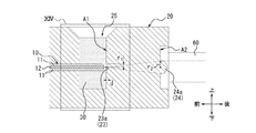
図4は、図1の光コネクタモジュール1を分解して示した分解斜視図である。図5は、図1のV-V矢線に沿う断面図である。図6は、図5のVI部に対応する拡大図である。 FIG. 4 is an exploded perspective view showing the optical connector module 1 of FIG. 1 in an exploded manner. FIG. 5 is a cross-sectional view taken along the line VV of FIG. FIG. 6 is an enlarged view corresponding to the VI portion of FIG.

図4に示すとおり、光コネクタ20は、光伝送路10の上方から基体40上に取り付けられる。すなわち、光コネクタ20は、第1基部21の下面21aが基体40の上面と当接して、光伝送路10の一部を覆った状態で配置される。第2基部22は、基体40の前端部から前方に突出し、第1基部21から下方に張り出すように配置される。すなわち、第2基部22は、その下面が光伝送路10の上下位置よりもさらに下方に位置するように突出する。 As shown in FIG. 4, the optical connector 20 is mounted on the substrate 40 from above the optical transmission line 10. That is, the optical connector 20 is arranged in a state where the lower surface 21a of the first base 21 abuts on the upper surface of the substrate 40 and covers a part of the optical transmission path 10. The second base portion 22 is arranged so as to project forward from the front end portion of the substrate 40 and project downward from the first base portion 21. That is, the second base portion 22 projects so that its lower surface is located further below the vertical position of the optical transmission line 10.

このとき、光伝送路10及び基体40と光コネクタ20の接着部26との間には、空隙Sが形成される(図5参照)。屈折率調整剤30は、空隙Sを満たすように下方から充填される。すなわち、屈折率調整剤30は、コア12と第1側面A1との間の空隙Sの屈折率を調整する。このとき、光コネクタ20の接着部26と屈折率調整剤30とが接着する。同様に、光伝送路10及び基体40の前端面と屈折率調整剤30とが接着する。特に、屈折率調整剤30は、第1レンズ部23及びコア12の端面と密着する。これにより、光伝送路10と光コネクタ20とは、屈折率調整剤30によって固定される。 At this time, a gap S is formed between the optical transmission path 10 and the substrate 40 and the adhesive portion 26 of the optical connector 20 (see FIG. 5). The refractive index adjusting agent 30 is filled from below so as to fill the void S. That is, the refractive index adjusting agent 30 adjusts the refractive index of the void S between the core 12 and the first side surface A1. At this time, the adhesive portion 26 of the optical connector 20 and the refractive index adjusting agent 30 are adhered to each other. Similarly, the front end surface of the optical transmission line 10 and the substrate 40 and the refractive index adjusting agent 30 adhere to each other. In particular, the refractive index adjusting agent 30 is in close contact with the end faces of the first lens portion 23 and the core 12. As a result, the optical transmission line 10 and the optical connector 20 are fixed by the refractive index adjusting agent 30.

屈折率調整剤30は、空隙Sのみを満たす構成に限定されず、例えば光コネクタ20の下面21aと基体40の上面との間に充填されてもよい。同様に、屈折率調整剤30は、光伝送路10を覆う光コネクタ20の凹部21bを満たすように充填されてもよい。基体40及び光伝送路10の少なくとも一方と光コネクタ20とは、このような方法で、屈折率調整剤30によって固定されてもよい。 The refractive index adjusting agent 30 is not limited to the configuration that fills only the void S, and may be filled, for example, between the lower surface 21a of the optical connector 20 and the upper surface of the substrate 40. Similarly, the refractive index adjusting agent 30 may be filled so as to fill the recess 21b of the optical connector 20 that covers the optical transmission path 10. At least one of the substrate 40 and the optical transmission line 10 and the optical connector 20 may be fixed by the refractive index adjusting agent 30 in this way.

基体40への取り付けの際に、光コネクタ20は、適宜な方法により位置決めされてもよい。例えば、光コネクタ20は、凹部21bの前後方向に沿った内側面の少なくとも一方が基体40から突出した光伝送路10の左右方向の端面と当接することで位置決めされてもよい。例えば、光コネクタ20は、基体40上に形成されたスタッドピンに対応する形状の凹部を有してもよい。このとき、光コネクタ20は、当該スタッドピンに凹部を係合させることで位置決めされてもよい。例えば、光コネクタ20は、基体40上に形成された凹部に対応する形状の凸部を有してもよい。このとき、光コネクタ20は、当該凹部に凸部を嵌合させることで位置決めされてもよい。 Upon attachment to the substrate 40, the optical connector 20 may be positioned by an appropriate method. For example, the optical connector 20 may be positioned by contacting at least one of the inner side surfaces of the recess 21b along the front-rear direction with the left-right end surface of the optical transmission path 10 protruding from the substrate 40. For example, the optical connector 20 may have a recess having a shape corresponding to a stud pin formed on the substrate 40. At this time, the optical connector 20 may be positioned by engaging the concave portion with the stud pin. For example, the optical connector 20 may have a convex portion having a shape corresponding to the concave portion formed on the substrate 40. At this time, the optical connector 20 may be positioned by fitting the convex portion into the concave portion.

以上により、光コネクタモジュール1の組み立てが完了する。 This completes the assembly of the optical connector module 1.

図6に示すとおり、光コネクタモジュール1が完成した状態で、第1側面A1は、コア12の前端面と対向する。特に、第1レンズ部23は、コア12の前端面と対向する。屈折率調整剤30は、第1レンズ部23とコア12の前端面との間に介在する。一例として、第1レンズ部23を構成するレンズ23aは、第1側面A1において凹形状として形成される。すなわち、レンズ23aは、凹レンズとして形成される。特に、レンズ23aは、光の伝搬方向、すなわち前後方向に沿った図6のような平面視において、略半円形状に形成されてもよい。レンズ23aの上下方向の半幅rは、光伝送路10のコア12の半径よりも大きくてもよい。レンズ23aにおいて、上下方向の全幅2rに対する伝搬方向に沿った幅dの比率が、1/2以下であってもよい。すなわち、d≦(2r)/2=rである。 As shown in FIG. 6, in the completed state of the optical connector module 1, the first side surface A1 faces the front end surface of the core 12. In particular, the first lens unit 23 faces the front end surface of the core 12. The refractive index adjusting agent 30 is interposed between the first lens portion 23 and the front end surface of the core 12. As an example, the lens 23a constituting the first lens portion 23 is formed as a concave shape on the first side surface A1. That is, the lens 23a is formed as a concave lens. In particular, the lens 23a may be formed in a substantially semicircular shape in a plan view as shown in FIG. 6 along the light propagation direction, that is, the front-back direction. The vertical half width r 1 of the lens 23a may be larger than the radius of the core 12 of the optical transmission line 10. In the lens 23a, the ratio of the width d along the propagation direction to the total width 2r 1 in the vertical direction may be 1/2 or less. That is, d ≦ (2r 1 ) / 2 = r 1 .

一方で、第2レンズ部24は、光コネクタ20の第2基部22を介して第1レンズ部23と対向する。一例として、第2レンズ部24を構成するレンズ24aは、第2側面A2において凸形状として形成される。すなわち、レンズ24aは、凸レンズとして形成される。特に、レンズ24aは、光の伝搬方向、すなわち前後方向に沿った図6のような平面視において、略半円形状に形成されてもよい。レンズ24aの上下方向の半幅rは、光伝送路10のコア12の半径よりも大きくてもよい。 On the other hand, the second lens portion 24 faces the first lens portion 23 via the second base portion 22 of the optical connector 20. As an example, the lens 24a constituting the second lens portion 24 is formed as a convex shape on the second side surface A2. That is, the lens 24a is formed as a convex lens. In particular, the lens 24a may be formed in a substantially semicircular shape in a plan view as shown in FIG. 6 along the light propagation direction, that is, the front-back direction. The vertical half width r 2 of the lens 24a may be larger than the radius of the core 12 of the optical transmission line 10.

図6を用いて、一例として、光伝送路10の前端面から光が出射する場合の光の伝搬の様子について説明する。すなわち、光伝送路10は、発光素子からの光を伝送するものとして説明する。これに限定されず、光伝送路10は、受光素子へと光を伝送してもよい。この場合、光の伝搬方向を真逆にした状態で以下の説明が適用され得るものと理解されたい。 With reference to FIG. 6, as an example, a state of light propagation when light is emitted from the front end surface of the optical transmission line 10 will be described. That is, the optical transmission path 10 will be described as transmitting the light from the light emitting element. Not limited to this, the optical transmission path 10 may transmit light to the light receiving element. In this case, it should be understood that the following explanation can be applied with the light propagation direction reversed.

屈折率調整剤30がコア12の屈折率と略同一の屈折率を有する材料によって構成される場合、屈折率調整剤30とコア12との境界面に入射した光のフレネル反射は、屈折率の整合によって抑制される。したがって、当該境界面に入射した光は、高い透過率で屈折率調整剤30の内部へと出射する。出射した光は、屈折率調整剤30の内部で回折効果によって拡がりながらレンズ23aへと入射する。光コネクタ20が屈折率調整剤30の屈折率と略同一の屈折率を有する材料によって構成される場合、光コネクタ20と屈折率調整剤30との境界面に入射した光のフレネル反射は、屈折率の整合によって抑制される。したがって、当該境界面に入射した光は、高い透過率で光コネクタ20、特に第2基部22の内部へと出射する。レンズ23aが凹レンズとして形成される場合、第2基部22の内部へと出射した光は、さらに拡がりながらレンズ24aへと入射する。レンズ24aが凸レンズとして形成される場合、外部と光コネクタ20との境界面に入射した光は、レンズ24aによってコリメートされる。このように、光コネクタモジュール1は、光伝送路10から出射した光をコリメートした状態で外部へと伝搬させる。 When the refractive index adjuster 30 is composed of a material having a refractive index substantially equal to that of the core 12, the Frenell reflection of light incident on the interface between the refractive index adjuster 30 and the core 12 is of the refractive index. Suppressed by alignment. Therefore, the light incident on the boundary surface is emitted to the inside of the refractive index adjusting agent 30 with high transmittance. The emitted light is incident on the lens 23a while spreading due to the diffraction effect inside the refractive index adjusting agent 30. When the optical connector 20 is made of a material having a refractive index substantially the same as the refractive index of the refractive index adjuster 30, the Frenell reflection of light incident on the interface between the optical connector 20 and the refractive index adjuster 30 is refracted. Suppressed by rate matching. Therefore, the light incident on the boundary surface is emitted to the inside of the optical connector 20, particularly the second base portion 22, with high transmittance. When the lens 23a is formed as a concave lens, the light emitted into the inside of the second base 22 is incident on the lens 24a while further spreading. When the lens 24a is formed as a convex lens, the light incident on the boundary surface between the outside and the optical connector 20 is collimated by the lens 24a. In this way, the optical connector module 1 propagates the light emitted from the optical transmission path 10 to the outside in a collimated state.

図7は、図6のVII部に対応する拡大図である。図7は、図1の光伝送路10の端面の様子を示す。図8は、変形例に係る光伝送路10の端面の様子を示した、図7に対応する拡大図である。 FIG. 7 is an enlarged view corresponding to part VII of FIG. FIG. 7 shows the state of the end face of the optical transmission line 10 of FIG. FIG. 8 is an enlarged view corresponding to FIG. 7, showing the state of the end face of the optical transmission line 10 according to the modified example.

図7に示すとおり、光伝送路10の前端面は、基体40の前端面と一致する。すなわち、クラッド11及びコア12の前端面が、基体40の前端面に沿って、同一平面上に形成される。しかしながらこれに限定されず、図8に示すとおり、光伝送路10の端面、特にコア12の端面は、光コネクタ20側に突出する曲面であってもよい。特に、コア12の端面は、クラッド11の端面よりも光コネクタ20側に突出する曲面であってもよい。 As shown in FIG. 7, the front end surface of the optical transmission line 10 coincides with the front end surface of the substrate 40. That is, the front end faces of the clad 11 and the core 12 are formed on the same plane along the front end faces of the substrate 40. However, the present invention is not limited to this, and as shown in FIG. 8, the end face of the optical transmission line 10, particularly the end face of the core 12, may be a curved surface protruding toward the optical connector 20. In particular, the end face of the core 12 may be a curved surface that protrudes toward the optical connector 20 from the end face of the clad 11.

以上のような第1実施形態に係る光コネクタモジュール1は、結合損失を低減しつつ、小型化に寄与できる。すなわち、光コネクタモジュール1は、第1側面A1においてコア12と対向する位置に第1レンズ部23が設けられることで、光の回折効果が生じる距離を短くして結合損失を低減できる。光コネクタモジュール1は、第1レンズ部23と光伝送路10との間の距離が短く、全体の小型化に寄与できる。特に、光コネクタモジュール1は、光の伝搬方向に沿った幅を低減できる。 The optical connector module 1 according to the first embodiment as described above can contribute to miniaturization while reducing the coupling loss. That is, in the optical connector module 1, the first lens portion 23 is provided at a position facing the core 12 on the first side surface A1, so that the distance at which the light diffraction effect occurs can be shortened and the coupling loss can be reduced. The optical connector module 1 has a short distance between the first lens unit 23 and the optical transmission line 10, and can contribute to overall miniaturization. In particular, the optical connector module 1 can reduce the width along the light propagation direction.

光コネクタモジュール1は、屈折率調整剤30を介在させることで、結合損失を低減できる。すなわち、光コネクタモジュール1は、回折効果による損失、外部からの異物による光の散乱又は吸収に伴う損失及びフレネル反射による損失を低減できる。 The optical connector module 1 can reduce the coupling loss by interposing the refractive index adjusting agent 30. That is, the optical connector module 1 can reduce the loss due to the diffraction effect, the loss due to scattering or absorption of light due to foreign matter from the outside, and the loss due to Fresnel reflection.

具体的には、光コネクタモジュール1は、コア12の屈折率と略同一の屈折率を有する屈折率調整剤30が光路中に配置されることで、空気中の場合と比較して回折効果による光の拡がりを抑制できる。これにより、光コネクタモジュール1は、回折効果によって第1レンズ部23と結合しない光の割合を低減できる。 Specifically, in the optical connector module 1, a refractive index adjusting agent 30 having a refractive index substantially the same as that of the core 12 is arranged in the optical path, so that the optical connector module 1 has a diffraction effect as compared with the case of being in the air. The spread of light can be suppressed. As a result, the optical connector module 1 can reduce the proportion of light that does not combine with the first lens unit 23 due to the diffraction effect.

また、屈折率調整剤30は、異物の混入を防止する役割も果たす。すなわち、光コネクタモジュール1は、空隙Sが屈折率調整剤30によって充填されることで、外部からの異物の混入を防止できる。これにより、光コネクタモジュール1は、外部からの異物による光の散乱又は吸収に伴う損失を防止して、結合損失を低減できる。 The refractive index adjusting agent 30 also plays a role of preventing foreign matter from being mixed. That is, in the optical connector module 1, the void S is filled with the refractive index adjusting agent 30, so that foreign matter can be prevented from being mixed from the outside. As a result, the optical connector module 1 can prevent the loss due to scattering or absorption of light due to foreign matter from the outside, and can reduce the coupling loss.

さらに、光コネクタモジュール1は、屈折率調整剤30の屈折率がコア12の屈折率と略同一であるので、互いの境界面におけるフレネル反射を抑制できる。すなわち、光コネクタモジュール1は、高い透過率で光をコア12から出射させ、結合効率を向上できる。 Further, in the optical connector module 1, since the refractive index of the refractive index adjusting agent 30 is substantially the same as the refractive index of the core 12, Fresnel reflection at the interface between the two can be suppressed. That is, the optical connector module 1 can emit light from the core 12 with a high transmittance and improve the coupling efficiency.

光コネクタモジュール1は、曲率する第2レンズ部24を有することで、第1レンズ部23と組み合わせた2つのレンズ部による光学調整を可能とする。すなわち、光コネクタモジュール1は、2つのレンズ部によって光学調整の自由度を向上できる。これにより、光コネクタモジュール1は、所望のビーム状態を有する出射光を容易に提供できる。 By having the second lens portion 24 having a curvature, the optical connector module 1 enables optical adjustment by two lens portions combined with the first lens portion 23. That is, the optical connector module 1 can improve the degree of freedom of optical adjustment by the two lens portions. Thereby, the optical connector module 1 can easily provide the emitted light having a desired beam state.

光コネクタモジュール1は、第1レンズ部23が凹レンズとして形成されることで、コア12から出射された光を強制的に拡げることができる。特に、光コネクタモジュール1は、第1側面A1においてコア12と対向する位置に凹レンズが設けられることで、屈折率調整剤30によって拡がりが抑制された光を出射後の早い段階で強制的に拡げることができる。 In the optical connector module 1, the first lens portion 23 is formed as a concave lens, so that the light emitted from the core 12 can be forcibly expanded. In particular, the optical connector module 1 is provided with a concave lens at a position facing the core 12 on the first side surface A1, so that the light whose spread is suppressed by the refractive index adjusting agent 30 is forcibly spread at an early stage after emission. be able to.

光コネクタモジュール1は、第2レンズ部24が凸レンズとして形成されることで、凹レンズの第1レンズ部23によって拡げられた光をコリメート光に変換できる。特に、光コネクタモジュール1は、第1レンズ部23及び第2レンズ部24による凹レンズ及び凸レンズの組合せによって、大口径のコリメート光を提供できる。これにより、光コネクタモジュール1は、より小さなスポットに効率良く集光可能なコリメート光を提供できる。すなわち、光コネクタモジュール1は、特性の良いコリメート光を出射できる。また、光コネクタモジュール1は、大口径のコリメート光によって光結合の許容範囲を広げることができる。換言すると、光コネクタモジュール1は、光結合の対象となる他のモジュールとの間で光軸がずれていたとしても、所定の許容範囲において光結合を可能とする。 The optical connector module 1 can convert the light spread by the first lens portion 23 of the concave lens into collimated light by forming the second lens portion 24 as a convex lens. In particular, the optical connector module 1 can provide collimated light having a large aperture by combining a concave lens and a convex lens by the first lens unit 23 and the second lens unit 24. As a result, the optical connector module 1 can provide collimated light that can be efficiently focused on a smaller spot. That is, the optical connector module 1 can emit collimated light having good characteristics. Further, the optical connector module 1 can expand the allowable range of optical coupling by collimating light having a large diameter. In other words, the optical connector module 1 enables optical coupling within a predetermined allowable range even if the optical axis is deviated from other modules to be optical coupled.

光コネクタモジュール1は、屈折率調整剤30が第1レンズ部23及びコア12の端面と密着することで、回折効果による光の拡がりをより効果的に抑制できる。これにより、光コネクタモジュール1は、回折効果によって第1レンズ部23と結合しない光の割合をさらに低減できる。また、光コネクタモジュール1は、当該構成によって光の伝搬方向に沿った空隙Sの幅を低減できる。これにより、光コネクタモジュール1は、全体の小型化、特に光の伝搬方向に沿った幅の低減に寄与できる。 In the optical connector module 1, the refractive index adjusting agent 30 is in close contact with the end faces of the first lens portion 23 and the core 12, so that the spread of light due to the diffraction effect can be suppressed more effectively. As a result, the optical connector module 1 can further reduce the proportion of light that does not combine with the first lens unit 23 due to the diffraction effect. Further, the optical connector module 1 can reduce the width of the gap S along the light propagation direction by the configuration. As a result, the optical connector module 1 can contribute to the overall miniaturization, particularly the reduction of the width along the light propagation direction.

光コネクタモジュール1は、屈折率調整剤30によって光伝送路10と光コネクタ20とが固定されることで、使用、経年劣化などによる光軸ずれを抑制できる。したがって、光コネクタモジュール1は、最初の位置決めによって互いの相対位置が定められた状態で、長期にわたって略同一の光学特性を維持できる。このように、光コネクタモジュール1は、製品としての品質を向上できる。 In the optical connector module 1, the optical transmission path 10 and the optical connector 20 are fixed by the refractive index adjusting agent 30, so that the optical axis shift due to use, deterioration over time, or the like can be suppressed. Therefore, the optical connector module 1 can maintain substantially the same optical characteristics for a long period of time in a state where the relative positions with respect to each other are determined by the initial positioning. In this way, the optical connector module 1 can improve the quality as a product.

光コネクタモジュール1は、光伝送路10の端面を光コネクタ20側に突出する曲面として維持することで、生産性の向上に寄与する。すなわち、光コネクタモジュール1は、光伝送路10の端面を研磨する必要がなく、生産工程の一部を省略できる。これにより、光コネクタモジュール1は、生産コストの削減にも寄与する。この場合、平面度が小さい平面である場合と比較して、光伝送路10の端面ではフレネル反射が増大する傾向にある。しかしながら、光コネクタモジュール1は、光伝送路10の端面を屈折率調整剤30と当接させることで、フレネル反射を抑制できる。光コネクタモジュール1は、光伝送路10の端面が光コネクタ20側に突出する曲面であることで、当該端面においてもレンズ効果を発揮できる。 The optical connector module 1 contributes to the improvement of productivity by maintaining the end surface of the optical transmission path 10 as a curved surface protruding toward the optical connector 20. That is, the optical connector module 1 does not need to polish the end face of the optical transmission line 10, and a part of the production process can be omitted. As a result, the optical connector module 1 also contributes to the reduction of production cost. In this case, Fresnel reflection tends to increase at the end face of the optical transmission line 10 as compared with the case where the flatness is small. However, the optical connector module 1 can suppress Fresnel reflection by bringing the end face of the optical transmission path 10 into contact with the refractive index adjusting agent 30. Since the end face of the optical transmission path 10 is a curved surface protruding toward the optical connector 20, the optical connector module 1 can exert a lens effect even on the end face.

光コネクタモジュール1は、コア12の端面がクラッド11の端面よりも光コネクタ20側に突出する曲面であることで、上記の関連する効果をより顕著に奏する。 The optical connector module 1 has a curved surface in which the end face of the core 12 protrudes toward the optical connector 20 from the end face of the clad 11, so that the above-mentioned related effect is more remarkably exhibited.

光コネクタモジュール1は、第1レンズ部23の半幅rがコア12の半径よりも大きいことで、コア12の端面から出射して拡がった光を第1レンズ部23によって漏れなく受けることができる。これにより、光コネクタモジュール1は、回折による結合損失を抑制できる。光コネクタモジュール1は、第2レンズ部24も同様の構成とすることで、回折による結合損失をさらに抑制できる。 Since the half width r 1 of the first lens portion 23 is larger than the radius of the core 12, the optical connector module 1 can receive the light emitted from the end face of the core 12 and spread by the first lens portion 23 without leakage. .. As a result, the optical connector module 1 can suppress the coupling loss due to diffraction. The optical connector module 1 has the same configuration as the second lens portion 24, so that the coupling loss due to diffraction can be further suppressed.

光コネクタモジュール1は、屈折率調整剤30と共に光コネクタ20もコア12の屈折率と略同一の屈折率を有する材料によって構成されることで、フレネル反射を抑制して、結合損失を低減できる。 In the optical connector module 1, the optical connector 20 together with the refractive index adjusting agent 30 is made of a material having a refractive index substantially the same as the refractive index of the core 12, so that Frenel reflection can be suppressed and the coupling loss can be reduced.

(第2実施形態)
図9は、第2実施形態に係る光コネクタモジュール1を示す斜視図である。第2実施形態に係る光コネクタモジュール1は、光伝送路10が光ファイバ13により構成される点で第1実施形態と異なる。以下では、第2実施形態に係る光コネクタモジュール1において、第1実施形態と共通する構成部については同一の符号を付す。共通する構成部及びその機能の説明については省略し、第1実施形態と異なる点について主に説明する。
(Second Embodiment)
FIG. 9 is a perspective view showing the optical connector module 1 according to the second embodiment. The optical connector module 1 according to the second embodiment is different from the first embodiment in that the optical transmission line 10 is composed of the optical fiber 13. In the following, in the optical connector module 1 according to the second embodiment, the same reference numerals are given to the components common to the first embodiment. The description of the common components and their functions will be omitted, and the differences from the first embodiment will be mainly described.

光伝送路10は、図9に示すとおり、複数の光ファイバ13により構成される。各光ファイバ13は、クラッド11及びコア12(図14参照)、並びに必要に応じて被膜を有している。クラッド11は、ガラスにより構成されてもよいし、樹脂によって構成されてもよい。同様に、コア12は、ガラスにより構成されてもよいし、樹脂によって構成されてもよい。各光ファイバ13の導波モードは、シングルモード及びマルチモードのいずれであってもよい。各光ファイバ13は、汎用のシングルモードファイバ、分散シフトシングルモードファイバ、ステップインデックスマルチモード光ファイバなど、任意の種類の光ファイバであってよい。複数の光ファイバ13は、シースによって覆われるように束ねられてもよいし、束ねられていなくてもよい。複数の光ファイバ13は、例えば、光コネクタ20の内部において、左右方向に一列に配列されている。 As shown in FIG. 9, the optical transmission line 10 is composed of a plurality of optical fibers 13. Each optical fiber 13 has a clad 11 and a core 12 (see FIG. 14), and, if necessary, a coating. The clad 11 may be made of glass or resin. Similarly, the core 12 may be made of glass or resin. The waveguide mode of each optical fiber 13 may be either a single mode or a multi-mode. Each optical fiber 13 may be any kind of optical fiber such as a general-purpose single mode fiber, a distributed shift single mode fiber, and a step index multimode optical fiber. The plurality of optical fibers 13 may or may not be bundled so as to be covered by a sheath. The plurality of optical fibers 13 are arranged in a row in the left-right direction, for example, inside the optical connector 20.

図10は、図9の光コネクタ20単体を示す斜視図である。 FIG. 10 is a perspective view showing a single optical connector 20 of FIG.

光コネクタ20は、光伝送路10のコア12の屈折率と略同一の屈折率を有する材料によって構成されてもよい。光コネクタ20は、基部51と、基部51と前方に連続するように形成される開口構成部52と、を有する。 The optical connector 20 may be made of a material having a refractive index substantially equal to that of the core 12 of the optical transmission line 10. The optical connector 20 has a base 51 and an opening component 52 formed so as to be continuous with the base 51 in the front.

開口構成部52には、光伝送路10を挿通するための開口部53が形成される。光コネクタ20は、複数の光ファイバ13を保持するための保持部54を基部51内に有する。光コネクタ20は、保持部54内において、複数のガイド溝55を有する。複数のガイド溝55は、光伝送路10を構成する複数の光ファイバ13をそれぞれ保持するための溝である。ガイド溝55の数は、光伝送路10を構成する光ファイバ13の本数以上である。 An opening 53 for inserting the optical transmission line 10 is formed in the opening configuration portion 52. The optical connector 20 has a holding portion 54 for holding a plurality of optical fibers 13 in the base portion 51. The optical connector 20 has a plurality of guide grooves 55 in the holding portion 54. The plurality of guide grooves 55 are grooves for holding each of the plurality of optical fibers 13 constituting the optical transmission line 10. The number of guide grooves 55 is equal to or greater than the number of optical fibers 13 constituting the optical transmission line 10.

光コネクタ20は、複数のガイド溝55の後方にそれぞれ連続する複数の貫通孔56を有する。光コネクタ20は、ガイドピン60を保持する保持孔57を備える。保持孔57は、基部51及び開口構成部52の左右両端を貫通するように、光コネクタ20の左右両端に一対形成される。 The optical connector 20 has a plurality of continuous through holes 56 behind the plurality of guide grooves 55, respectively. The optical connector 20 includes a holding hole 57 for holding the guide pin 60. A pair of holding holes 57 are formed on the left and right ends of the optical connector 20 so as to penetrate the left and right ends of the base 51 and the opening component 52.

光コネクタ20は、基部51の上面を切欠いた切欠部25を有する。すなわち、切欠部25は、略凹形状として形成される。光コネクタ20は、切欠部25の内面の一部を構成する第1側面A1に設けられた第1レンズ部23を有する。光コネクタ20は、光の伝搬方向において第1側面A1と反対側の第2側面A2に設けられた第2レンズ部24を有する。 The optical connector 20 has a notch 25 having a notch on the upper surface of the base 51. That is, the notch 25 is formed in a substantially concave shape. The optical connector 20 has a first lens portion 23 provided on the first side surface A1 forming a part of the inner surface of the notch portion 25. The optical connector 20 has a second lens portion 24 provided on the second side surface A2 opposite to the first side surface A1 in the light propagation direction.

図11は、図9の光コネクタモジュール1を分解して示した分解斜視図である。図12は、図9のXII-XII矢線に沿う断面図である。図13は、図12のXIII部に対応する拡大図である。 FIG. 11 is an exploded perspective view showing the optical connector module 1 of FIG. 9 in an exploded manner. FIG. 12 is a cross-sectional view taken along the XII-XII arrow line of FIG. FIG. 13 is an enlarged view corresponding to the XIII portion of FIG.

図11に示すとおり、光伝送路10は、光コネクタ20に前方から挿入される。光伝送路10は、光伝送路10のクラッド11及びコア12の端部が貫通孔56より後方に露出した状態で光コネクタ20により保持される。屈折率調整剤30は、切欠部25を満たすように上方から充填される。左右一対のガイドピン60が、光伝送路10を保持した光コネクタ20の保持孔57に挿入される。 As shown in FIG. 11, the optical transmission line 10 is inserted into the optical connector 20 from the front. The optical transmission line 10 is held by the optical connector 20 in a state where the end portions of the clad 11 and the core 12 of the optical transmission line 10 are exposed behind the through hole 56. The refractive index adjusting agent 30 is filled from above so as to fill the notch 25. A pair of left and right guide pins 60 are inserted into the holding holes 57 of the optical connector 20 that holds the optical transmission path 10.

以上により、光コネクタモジュール1の組み立てが完了する。 This completes the assembly of the optical connector module 1.

図12及び図13に示すとおり、光コネクタモジュール1が完成した状態で、第1レンズ部23、第2レンズ部24及び屈折率調整剤30は、第1実施形態と同様に構成される。光伝送路10の後端面から光が出射する場合の光の伝搬の様子についても同様である。第2レンズ部24から光が入射する場合の光の伝搬の様子についても同様であり、光の伝搬方向を真逆にした状態で第1実施形態における説明が適用され得るものと理解されたい。 As shown in FIGS. 12 and 13, in a state where the optical connector module 1 is completed, the first lens unit 23, the second lens unit 24, and the refractive index adjusting agent 30 are configured in the same manner as in the first embodiment. The same applies to the state of light propagation when light is emitted from the rear end surface of the optical transmission line 10. The same applies to the state of light propagation when light is incident from the second lens unit 24, and it should be understood that the description in the first embodiment can be applied with the light propagation directions reversed.

図14は、図13のXIV部に対応する拡大図である。図14は、図9の光伝送路10の端面の様子を示す。図15は、変形例に係る光伝送路10の端面の様子を示した、図14に対応する拡大図である。 FIG. 14 is an enlarged view corresponding to the XIV portion of FIG. FIG. 14 shows the state of the end face of the optical transmission line 10 of FIG. FIG. 15 is an enlarged view corresponding to FIG. 14, showing the state of the end face of the optical transmission line 10 according to the modified example.

図14に示すとおり、光伝送路10の端面は、光コネクタ20側、特に第1側面A1側に突出する曲面である。一例として、光伝送路10の端面は、クラッド11及びコア12の端面が同一曲面となるように構成される。しかしながらこれに限定されず、図15に示すとおり、光伝送路10の端面、特にコア12の端面は、クラッド11の端面よりも第1側面A1側に突出する曲面であってもよい。 As shown in FIG. 14, the end surface of the optical transmission line 10 is a curved surface protruding toward the optical connector 20 side, particularly the first side surface A1 side. As an example, the end face of the optical transmission line 10 is configured so that the end faces of the clad 11 and the core 12 have the same curved surface. However, the present invention is not limited to this, and as shown in FIG. 15, the end face of the optical transmission line 10, particularly the end face of the core 12, may be a curved surface protruding toward the first side surface A1 side from the end face of the clad 11.

以上のような第2実施形態に係る光コネクタモジュール1は、第1実施形態と同様の効果を奏する。 The optical connector module 1 according to the second embodiment as described above has the same effect as that of the first embodiment.

(第3実施形態)
図16は、第3実施形態に係る光コネクタモジュール1を示す斜視図である。図17は、図16のXVII-XVII矢線に沿う断面の一部を拡大した拡大断面図である。第3実施形態に係る光コネクタモジュール1は、第1実施形態に係る光学系と第2実施形態に係る光学系とを組み合わせたものである。以下では、第3実施形態に係る光コネクタモジュール1において、第1実施形態及び第2実施形態と共通する構成部については同一の符号を付す。共通する構成部及びその機能の説明については省略し、第1実施形態及び第2実施形態と異なる点について主に説明する。
(Third Embodiment)
FIG. 16 is a perspective view showing the optical connector module 1 according to the third embodiment. FIG. 17 is an enlarged cross-sectional view of a part of the cross section taken along the XVII-XVII arrow line of FIG. The optical connector module 1 according to the third embodiment is a combination of the optical system according to the first embodiment and the optical system according to the second embodiment. In the following, in the optical connector module 1 according to the third embodiment, the same reference numerals are given to the components common to the first embodiment and the second embodiment. The description of the common components and their functions will be omitted, and the differences from the first embodiment and the second embodiment will be mainly described.

図16に示すとおり、第3実施形態に係る光コネクタモジュール1は、第1実施形態に係る光コネクタ20aと第2実施形態に係る光コネクタ20bとを接続して、第1実施形態に係る光伝送路10aと第2実施形態に係る光伝送路10bとを光結合する。 As shown in FIG. 16, the optical connector module 1 according to the third embodiment connects the optical connector 20a according to the first embodiment and the optical connector 20b according to the second embodiment, and the optical connector module 1 according to the first embodiment is connected. The transmission line 10a and the optical transmission line 10b according to the second embodiment are optically coupled.

より具体的には、光コネクタ20aと光コネクタ20bとを上下左右方向の位置が略一致するように、前後方向に並べる。この状態で、一対のガイドピン60が、貫通孔22aに挿入される。これにより、光コネクタ20aと光コネクタ20bとが接続する。このとき、貫通孔22aによって、光コネクタ20aに対する光コネクタ20bの位置が決定される。これにより、図17に示すとおり、光伝送路10aの端面及び光伝送路10bの端面が略同一の光軸上に配置され、光伝送路10aを構成する光導波路と、光伝送路10bを構成する対応する複数の光ファイバ13とが、それぞれ光結合する。 More specifically, the optical connector 20a and the optical connector 20b are arranged in the front-rear direction so that the positions in the up-down, left-right directions are substantially the same. In this state, the pair of guide pins 60 are inserted into the through holes 22a. As a result, the optical connector 20a and the optical connector 20b are connected. At this time, the position of the optical connector 20b with respect to the optical connector 20a is determined by the through hole 22a. As a result, as shown in FIG. 17, the end face of the optical transmission line 10a and the end face of the optical transmission line 10b are arranged on substantially the same optical axis, and the optical waveguide constituting the optical transmission line 10a and the optical transmission line 10b are configured. The corresponding plurality of optical fibers 13 are optically coupled to each other.

例えば、光伝送路10aから出射した光は、屈折率調整剤30a、第1レンズ部231及び第2レンズ部241を通過して、コリメート光として出射する。コリメート光は、第2レンズ部242、第1レンズ部232及び屈折率調整剤30bを通過して、光ファイバ13へと入射する。光の伝搬方向が真逆の場合であっても同様の説明が適用されるものとする。 For example, the light emitted from the optical transmission path 10a passes through the refractive index adjusting agent 30a, the first lens unit 231 and the second lens unit 241 and is emitted as collimated light. The collimated light passes through the second lens portion 242, the first lens portion 232, and the refractive index adjusting agent 30b, and is incident on the optical fiber 13. The same explanation shall be applied even when the light propagation direction is exactly the opposite.

以上のような第3実施形態に係る光コネクタモジュール1は、第1実施形態及び第2実施形態と同様の効果を奏する。第3実施形態に係る光コネクタモジュール1は、大口径のコリメート光によって、効率良い集光可能性かつ広範な光結合の許容範囲を実現した状態で、異なる2つの光伝送路10a、10bを光結合できる。 The optical connector module 1 according to the third embodiment as described above has the same effects as those of the first embodiment and the second embodiment. The optical connector module 1 according to the third embodiment illuminates two different optical transmission lines 10a and 10b in a state where efficient light collection possibility and a wide range of optical coupling tolerance are realized by collimated light having a large diameter. Can be combined.

本発明は、その精神又はその本質的な特徴から離れることなく、上述した実施形態以外の他の所定の形態で実現できることは当業者にとって明白である。したがって、先の記述は例示的なものであり、これに限定されるものではない。発明の範囲は、先の記述によってではなく、付加した請求項によって定義される。あらゆる変更のうちその均等の範囲内にあるいくつかの変更は、その中に包含されるものとする。 It will be apparent to those skilled in the art that the present invention can be realized in certain embodiments other than those described above, without departing from its spirit or its essential features. Therefore, the above description is exemplary and is not limited thereto. The scope of the invention is defined by the added claims, not by the earlier description. Any changes that are within their equality shall be included therein.

例えば、上記では、屈折率調整剤30は、空隙S全体に充填されるものとして説明したが、これに限定されない。屈折率調整剤30は、第1側面A1とコア12の端面との間に介在し、かつ、所望の光学特性が得られるのであれば、空隙Sの一部にのみ配置されてもよい。 For example, in the above description, the refractive index adjusting agent 30 is described as being filled in the entire void S, but the present invention is not limited to this. The refractive index adjusting agent 30 may be disposed only in a part of the void S as long as it is interposed between the first side surface A1 and the end surface of the core 12 and the desired optical characteristics can be obtained.

上記では、第1レンズ部23及び第2レンズ部24の形状は、平面視において略半円形であるものとして説明したが、これに限定されない。第1レンズ部23及び第2レンズ部24の形状は、球面であってもよいし、非球面であってもよい。 In the above, the shapes of the first lens portion 23 and the second lens portion 24 have been described as being substantially semicircular in a plan view, but the shape is not limited thereto. The shapes of the first lens portion 23 and the second lens portion 24 may be spherical or aspherical.

第1レンズ部23は、d≦(2r)/2=rの条件を満たす構成に限定されない。所望の光学特性が得られるのであれば、第1レンズ部23において、全幅2rに対する幅dの比率が、1/2よりも大きくてもよい。 The first lens unit 23 is not limited to a configuration that satisfies the condition of d ≦ (2r 1 ) / 2 = r 1. In the first lens unit 23, the ratio of the width d to the total width 2r 1 may be larger than 1/2 as long as the desired optical characteristics can be obtained.

第1レンズ部23は、凹レンズであるものとして説明したがこれに限定されない。所望の光学特性が得られるのであれば、第1レンズ部23は、凸レンズなどの任意のタイプのレンズであってもよい。 The first lens unit 23 has been described as being a concave lens, but the present invention is not limited to this. The first lens unit 23 may be any type of lens such as a convex lens as long as the desired optical characteristics can be obtained.

所望の光学特性が得られるのであれば、光コネクタ20は、第2レンズ部24を有さなくてもよい。また、第2レンズ部24は、凸レンズであることに限定されず、凹レンズなどの任意のタイプのレンズであってもよい。 The optical connector 20 may not have the second lens portion 24 as long as the desired optical characteristics can be obtained. Further, the second lens unit 24 is not limited to a convex lens, and may be any type of lens such as a concave lens.

光導波路又は光ファイバ13によって構成される光伝送路10の端面は、平面であってもよいし、曲面であってもよい。当該端面は、曲面により形成される場合、凹面であってもよいし、凸面であってもよい。特に、光伝送路10のクラッド11及びコア12の端面の形状及び位置は、図7、8、14及び15に示したものに限定されない。所望の光学特性が得られるのであれば、光伝送路10のクラッド11及びコア12の端面は、任意の形状で任意の位置に配置されてもよい。例えば、コア12と第1レンズ部23とが離間しており、その間に屈折率調整剤30が充填されているのであれば、クラッド11は、光コネクタ20、特に第1側面A1と当接してもよい。 The end face of the optical transmission line 10 composed of the optical waveguide or the optical fiber 13 may be a flat surface or a curved surface. When the end face is formed by a curved surface, the end face may be a concave surface or a convex surface. In particular, the shapes and positions of the end faces of the clad 11 and the core 12 of the optical transmission line 10 are not limited to those shown in FIGS. 7, 8, 14 and 15. The end faces of the clad 11 and the core 12 of the optical transmission line 10 may be arranged in any shape and at any position as long as the desired optical characteristics can be obtained. For example, if the core 12 and the first lens portion 23 are separated from each other and the refractive index adjusting agent 30 is filled between them, the clad 11 comes into contact with the optical connector 20, particularly the first side surface A1. May be good.

1 光コネクタモジュール
10、10a、10b 光伝送路
11 クラッド
12 コア
13 光ファイバ
20、20a、20b 光コネクタ
21 第1基部
21a 下面
21b 凹部
22 第2基部
22a 貫通孔
23、231、232 第1レンズ部
23a レンズ
24、241、242 第2レンズ部
24a レンズ
25 切欠部
26 接着部
30、30a、30b 屈折率調整剤
40 基体
51 基部
52 開口構成部
53 開口部
54 保持部
55 ガイド溝
56 貫通孔
57 保持孔
60 ガイドピン
A1 第1側面
A2 第2側面
S 空隙
1 Optical connector module 10, 10a, 10b Optical transmission path 11 Clad 12 Core 13 Optical fiber 20, 20a, 20b Optical connector 21 First base 21a Bottom surface 21b Recess 22 Second base 22a Through hole 23, 231, 232 First lens unit 23a Lens 24, 241, 242 Second lens part 24a Lens 25 Notch part 26 Adhesive part 30, 30a, 30b Refractive index adjuster 40 Base 51 Base 52 Opening component 53 Opening 54 Holding 55 Guide groove 56 Through hole 57 Holding Hole 60 Guide pin A1 First side surface A2 Second side surface S Air gap

Claims (4)

基体に積層されるコア及びクラッドを有する光伝送路と、
基部と、前記光伝送路の端面及び前記基体の端面と対向する前記基部の内面を第1側面まで切欠いた切欠部と、前記切欠部に形成されている前記第1側面と、前記基部において前記第1側面と反対側に設けられた第2側面と、を有し、前記光伝送路と光学的に結合する光コネクタと、
前記光伝送路の端面及び前記基体の端面と前記第1側面との間に介在する屈折率調整剤と、
を備え、
前記第1側面には、前記コアと対向する位置に凹形状として曲率し、凹レンズとして形成される第1レンズ部が設けられ、
前記第2側面には、前記第1レンズ部と対向する位置に凸形状として曲率し、凸レンズとして形成される第2レンズ部が設けられ、
前記屈折率調整剤は、前記切欠部及び前記第1側面における前記凹レンズの前記凹形状内に充填され、
前記基部の前記内面において最も前記基体側に位置する面は、前記基体の端面と離間し、かつ前記屈折率調整剤と接着する、
光コネクタモジュール。
An optical transmission line having a core and a cladding laminated on a substrate,
A base, said optical transmission path end face and the end face opposite to the notch the inner face of a notched to the first side surface of the base of said substrate, said first side surface which is formed on the notch portion, the in the base An optical connector having a second side surface provided on the opposite side to the first side surface and optically coupled to the optical transmission line.
The refractive index control agent that Mashimasu through between the first side surface and the end face of the end face and the base of the optical transmission line,
Equipped with
The first side surface is provided with a first lens portion that is formed as a concave lens by being curved as a concave shape at a position facing the core.
The second side surface is provided with a second lens portion that is curved as a convex shape at a position facing the first lens portion and is formed as a convex lens.
The refractive index adjusting agent is filled in the concave shape of the concave lens on the notch and the first side surface.
The surface of the inner surface of the base, which is located closest to the substrate, is separated from the end surface of the substrate and adheres to the refractive index adjusting agent.
Optical connector module.
前記屈折率調整剤は、前記光コネクタと前記光伝送路とを固定する、
請求項に記載の光コネクタモジュール。
The refractive index adjusting agent fixes the optical connector and the optical transmission line.
The optical connector module according to claim 1.
前記光伝送路の端面は、前記光コネクタ側に突出する曲面である、
請求項1又は2に記載の光コネクタモジュール。
The end face of the optical transmission line is a curved surface protruding toward the optical connector side.
The optical connector module according to claim 1 or 2.
前記コアの前記端面は、前記クラッドの端面よりも前記光コネクタ側に突出する曲面である、
請求項1乃至3のいずれか1項に記載の光コネクタモジュール。
The end face of the core is a curved surface that protrudes toward the optical connector side from the end face of the clad.
The optical connector module according to any one of claims 1 to 3.
JP2018056718A 2017-06-16 2018-03-23 Optical connector module Active JP6979381B2 (en)

Priority Applications (1)

Application Number Priority Date Filing Date Title
JP2018056718A JP6979381B2 (en) 2017-06-16 2018-03-23 Optical connector module

Applications Claiming Priority (2)

Application Number Priority Date Filing Date Title
JP2018500348A JP6401888B1 (en) 2017-06-16 2017-06-16 Optical connector module
JP2018056718A JP6979381B2 (en) 2017-06-16 2018-03-23 Optical connector module

Related Parent Applications (1)

Application Number Title Priority Date Filing Date
JP2018500348A Division JP6401888B1 (en) 2017-06-16 2017-06-16 Optical connector module

Publications (3)

Publication Number Publication Date
JP2019003169A JP2019003169A (en) 2019-01-10
JP2019003169A5 JP2019003169A5 (en) 2020-08-06
JP6979381B2 true JP6979381B2 (en) 2021-12-15

Family

ID=65007973

Family Applications (1)

Application Number Title Priority Date Filing Date
JP2018056718A Active JP6979381B2 (en) 2017-06-16 2018-03-23 Optical connector module

Country Status (1)

Country Link
JP (1) JP6979381B2 (en)

Families Citing this family (1)

* Cited by examiner, † Cited by third party
Publication number Priority date Publication date Assignee Title
JP1670517S (en) 2020-05-27 2020-10-19

Family Cites Families (12)

* Cited by examiner, † Cited by third party
Publication number Priority date Publication date Assignee Title
NL172188C (en) * 1977-02-11 1983-07-18 Deutsch Co Elec Comp SYSTEM FOR COUPLING AN OPTICAL FIBER TO AN OPTICAL COMPONENT THAT PROVIDES OR RECORDS OPTICAL ENERGY.
JPS5988713A (en) * 1982-11-12 1984-05-22 Nippon Denso Co Ltd Optical connector
US4523843A (en) * 1983-08-04 1985-06-18 Gte Laboratories Incorporated Optical test set-up for expanded beam connector
JP2001350037A (en) * 2000-04-05 2001-12-21 Canon Inc Plastic optical fiber with lens member, optical fiber coupler, connector structure thereof and connecting method
JP5357845B2 (en) * 2010-08-31 2013-12-04 アンリツ株式会社 Polarization mode dispersion stress generation method and apparatus
JP2013020027A (en) * 2011-07-08 2013-01-31 Fujitsu Ltd Optical transmission line and method of manufacturing the same
JP2014059479A (en) * 2012-09-18 2014-04-03 Fujitsu Ltd Manufacturing method of optical connector, and optical connector
JP2014164270A (en) * 2013-02-27 2014-09-08 Sumitomo Bakelite Co Ltd Ferrule, optoelectronic hybrid substrate and electronic device
JP6457723B2 (en) * 2014-03-28 2019-01-23 富士通株式会社 Optical waveguide coupler and manufacturing method thereof
JP6502028B2 (en) * 2014-06-24 2019-04-17 富士通コンポーネント株式会社 Optical connector manufacturing method and optical connector
JP6390291B2 (en) * 2014-09-12 2018-09-19 住友電気工業株式会社 Optical connector
WO2017072993A1 (en) * 2015-10-28 2017-05-04 京セラコネクタプロダクツ株式会社 Optical connector, optical connector system, and active optical cable provided with same

Also Published As

Publication number Publication date
JP2019003169A (en) 2019-01-10

Similar Documents

Publication Publication Date Title
JP6401888B1 (en) Optical connector module
JP5127546B2 (en) Optical connector
JPWO2004104666A1 (en) Optical element, optical transmission unit and optical transmission system
WO2005006032A1 (en) Optical path change type optical coupling element
JP6979381B2 (en) Optical connector module
TWI742236B (en) Optical coupling system and method for optical coupling system
JP2015179125A (en) Optical receptacle and optical module having the same
WO2020137070A1 (en) Connector system, optical connection method, and optical connection member
JP2017040887A (en) Optical waveguide connector
WO2022024855A1 (en) Optical connector and optical connector module
JP6681751B2 (en) Optical receptacle and optical module
JP2008203546A (en) Lens assembly and optical module using the same
WO2022014419A1 (en) Optical connector and optical connector module
JPWO2018042984A1 (en) Optical connection structure
TWI608263B (en) Optical socket and light module with it
JP2008233556A (en) Lens case and optical module
WO2016175126A1 (en) Optical transmission module
JP2010169755A (en) Optical path change mirror
JP5282988B2 (en) Optical connector
JP2007212902A (en) Optical transmitting/receiving apparatus

Legal Events

Date Code Title Description
A521 Written amendment

Free format text: JAPANESE INTERMEDIATE CODE: A523

Effective date: 20200609

A621 Written request for application examination

Free format text: JAPANESE INTERMEDIATE CODE: A621

Effective date: 20200609

A977 Report on retrieval

Free format text: JAPANESE INTERMEDIATE CODE: A971007

Effective date: 20210308

A131 Notification of reasons for refusal

Free format text: JAPANESE INTERMEDIATE CODE: A131

Effective date: 20210316

A521 Written amendment

Free format text: JAPANESE INTERMEDIATE CODE: A523

Effective date: 20210512

TRDD Decision of grant or rejection written
A01 Written decision to grant a patent or to grant a registration (utility model)

Free format text: JAPANESE INTERMEDIATE CODE: A01

Effective date: 20211026

A61 First payment of annual fees (during grant procedure)

Free format text: JAPANESE INTERMEDIATE CODE: A61

Effective date: 20211115

R150 Certificate of patent or registration of utility model

Ref document number: 6979381

Country of ref document: JP

Free format text: JAPANESE INTERMEDIATE CODE: R150