JP6979372B2 - Battery module - Google Patents
Battery module Download PDFInfo
- Publication number
- JP6979372B2 JP6979372B2 JP2018031500A JP2018031500A JP6979372B2 JP 6979372 B2 JP6979372 B2 JP 6979372B2 JP 2018031500 A JP2018031500 A JP 2018031500A JP 2018031500 A JP2018031500 A JP 2018031500A JP 6979372 B2 JP6979372 B2 JP 6979372B2
- Authority
- JP
- Japan
- Prior art keywords
- secondary battery
- stacking direction
- terminal
- terminals
- bus bar
- Prior art date
- Legal status (The legal status is an assumption and is not a legal conclusion. Google has not performed a legal analysis and makes no representation as to the accuracy of the status listed.)
- Active
Links
Images


Classifications
-
- H—ELECTRICITY
- H01—ELECTRIC ELEMENTS
- H01M—PROCESSES OR MEANS, e.g. BATTERIES, FOR THE DIRECT CONVERSION OF CHEMICAL ENERGY INTO ELECTRICAL ENERGY
- H01M10/00—Secondary cells; Manufacture thereof
- H01M10/04—Construction or manufacture in general
- H01M10/0481—Compression means other than compression means for stacks of electrodes and separators
-
- H—ELECTRICITY
- H01—ELECTRIC ELEMENTS
- H01M—PROCESSES OR MEANS, e.g. BATTERIES, FOR THE DIRECT CONVERSION OF CHEMICAL ENERGY INTO ELECTRICAL ENERGY
- H01M10/00—Secondary cells; Manufacture thereof
- H01M10/05—Accumulators with non-aqueous electrolyte
- H01M10/058—Construction or manufacture
-
- H—ELECTRICITY
- H01—ELECTRIC ELEMENTS
- H01M—PROCESSES OR MEANS, e.g. BATTERIES, FOR THE DIRECT CONVERSION OF CHEMICAL ENERGY INTO ELECTRICAL ENERGY
- H01M50/00—Constructional details or processes of manufacture of the non-active parts of electrochemical cells other than fuel cells, e.g. hybrid cells
- H01M50/50—Current conducting connections for cells or batteries
- H01M50/502—Interconnectors for connecting terminals of adjacent batteries; Interconnectors for connecting cells outside a battery casing
- H01M50/507—Interconnectors for connecting terminals of adjacent batteries; Interconnectors for connecting cells outside a battery casing comprising an arrangement of two or more busbars within a container structure, e.g. busbar modules
-
- H—ELECTRICITY
- H01—ELECTRIC ELEMENTS
- H01M—PROCESSES OR MEANS, e.g. BATTERIES, FOR THE DIRECT CONVERSION OF CHEMICAL ENERGY INTO ELECTRICAL ENERGY
- H01M50/00—Constructional details or processes of manufacture of the non-active parts of electrochemical cells other than fuel cells, e.g. hybrid cells
- H01M50/20—Mountings; Secondary casings or frames; Racks, modules or packs; Suspension devices; Shock absorbers; Transport or carrying devices; Holders
- H01M50/204—Racks, modules or packs for multiple batteries or multiple cells
- H01M50/207—Racks, modules or packs for multiple batteries or multiple cells characterised by their shape
- H01M50/209—Racks, modules or packs for multiple batteries or multiple cells characterised by their shape adapted for prismatic or rectangular cells
-
- H—ELECTRICITY
- H01—ELECTRIC ELEMENTS
- H01M—PROCESSES OR MEANS, e.g. BATTERIES, FOR THE DIRECT CONVERSION OF CHEMICAL ENERGY INTO ELECTRICAL ENERGY
- H01M50/00—Constructional details or processes of manufacture of the non-active parts of electrochemical cells other than fuel cells, e.g. hybrid cells
- H01M50/20—Mountings; Secondary casings or frames; Racks, modules or packs; Suspension devices; Shock absorbers; Transport or carrying devices; Holders
- H01M50/271—Lids or covers for the racks or secondary casings
-
- H—ELECTRICITY
- H01—ELECTRIC ELEMENTS
- H01M—PROCESSES OR MEANS, e.g. BATTERIES, FOR THE DIRECT CONVERSION OF CHEMICAL ENERGY INTO ELECTRICAL ENERGY
- H01M50/00—Constructional details or processes of manufacture of the non-active parts of electrochemical cells other than fuel cells, e.g. hybrid cells
- H01M50/50—Current conducting connections for cells or batteries
- H01M50/543—Terminals
- H01M50/547—Terminals characterised by the disposition of the terminals on the cells
- H01M50/55—Terminals characterised by the disposition of the terminals on the cells on the same side of the cell
-
- H—ELECTRICITY
- H01—ELECTRIC ELEMENTS
- H01M—PROCESSES OR MEANS, e.g. BATTERIES, FOR THE DIRECT CONVERSION OF CHEMICAL ENERGY INTO ELECTRICAL ENERGY
- H01M50/00—Constructional details or processes of manufacture of the non-active parts of electrochemical cells other than fuel cells, e.g. hybrid cells
- H01M50/50—Current conducting connections for cells or batteries
- H01M50/543—Terminals
- H01M50/552—Terminals characterised by their shape
- H01M50/553—Terminals adapted for prismatic, pouch or rectangular cells
-
- H—ELECTRICITY
- H01—ELECTRIC ELEMENTS
- H01M—PROCESSES OR MEANS, e.g. BATTERIES, FOR THE DIRECT CONVERSION OF CHEMICAL ENERGY INTO ELECTRICAL ENERGY
- H01M50/00—Constructional details or processes of manufacture of the non-active parts of electrochemical cells other than fuel cells, e.g. hybrid cells
- H01M50/50—Current conducting connections for cells or batteries
- H01M50/543—Terminals
- H01M50/564—Terminals characterised by their manufacturing process
- H01M50/566—Terminals characterised by their manufacturing process by welding, soldering or brazing
-
- Y—GENERAL TAGGING OF NEW TECHNOLOGICAL DEVELOPMENTS; GENERAL TAGGING OF CROSS-SECTIONAL TECHNOLOGIES SPANNING OVER SEVERAL SECTIONS OF THE IPC; TECHNICAL SUBJECTS COVERED BY FORMER USPC CROSS-REFERENCE ART COLLECTIONS [XRACs] AND DIGESTS
- Y02—TECHNOLOGIES OR APPLICATIONS FOR MITIGATION OR ADAPTATION AGAINST CLIMATE CHANGE
- Y02E—REDUCTION OF GREENHOUSE GAS [GHG] EMISSIONS, RELATED TO ENERGY GENERATION, TRANSMISSION OR DISTRIBUTION
- Y02E60/00—Enabling technologies; Technologies with a potential or indirect contribution to GHG emissions mitigation
- Y02E60/10—Energy storage using batteries
Landscapes
- Chemical & Material Sciences (AREA)
- Chemical Kinetics & Catalysis (AREA)
- Electrochemistry (AREA)
- General Chemical & Material Sciences (AREA)
- Engineering & Computer Science (AREA)
- Manufacturing & Machinery (AREA)
- Connection Of Batteries Or Terminals (AREA)
- Battery Mounting, Suspending (AREA)
Description
本発明は複数の二次電池2を備える二次電池モジュールに関する。
The present invention relates to a secondary battery module including a plurality of
従来、再充電可能な二次電池の分野では、鉛電池、ニッケル−カドミウム電池、ニッケル−水素電池等の水溶液系電池が主流であった。しかしながら、電気機器の小型化、軽量化が進むにつれ、高エネルギー密度を有するリチウム二次電池が着目され、その研究、開発及び商品化が急速に進められた。 Conventionally, in the field of rechargeable secondary batteries, aqueous batteries such as lead batteries, nickel-cadmium batteries, and nickel-hydrogen batteries have been the mainstream. However, as the miniaturization and weight reduction of electric devices have progressed, attention has been paid to lithium secondary batteries having a high energy density, and their research, development and commercialization have been rapidly promoted.
一方、地球温暖化や枯渇燃料の問題から電気自動車(EV)や駆動の一部を電気モーターで補助するハイブリッド電気自動車(HEV)が各自動車メーカーで開発され、その電源として高容量で高出力な二次電池が求められるようになってきた。このような要求に合致する電源として、高電圧を有する非水溶液系のリチウム二次電池が注目されている。特に角形リチウム二次電池はパック化した際の体積効率が優れているため、HEV用あるいはEV用として角形リチウム二次電池の開発への期待が高まっている。 On the other hand, due to the problems of global warming and depleted fuel, electric vehicles (EVs) and hybrid electric vehicles (HEVs) that partially assist the drive with electric motors have been developed by each automobile manufacturer, and have high capacity and high output as their power source. Secondary batteries are being sought after. As a power source that meets such demands, a non-aqueous solution lithium secondary battery having a high voltage is attracting attention. In particular, since square lithium secondary batteries have excellent volumetric efficiency when packed, expectations are rising for the development of square lithium secondary batteries for HEVs or EVs.
複数の二次電池をパックとする場合、複数の二次電池がずれることなく配列するにはガイド等の部材が必要となる。 When a plurality of secondary batteries are packed, a member such as a guide is required to arrange the plurality of secondary batteries without shifting.
例えば、特許文献1には、多数個の二次電池をガイド壁を有した絶縁材を介して積層する二次電池モジュールが提案されている。
For example,
モジュール構造を安価に製造しようとする場合、特許文献1に開示されるような絶縁材を安価なシート材によって置き換えることが考えられる。しかし、この場合、二次電池をずれることなく配列することが容易でなくなる。
When the modular structure is to be manufactured at low cost, it is conceivable to replace the insulating material as disclosed in
これに対して、例えば複数の二次電池の端子を特許文献1に開示されるようなバスバーケースの孔に挿入することで配列することが可能となる。
On the other hand, for example, the terminals of a plurality of secondary batteries can be arranged by inserting them into the holes of the bus bar case as disclosed in
しかし、二次電池を積層方向に圧縮した状態で固定する場合、圧縮前と圧縮後とで二次電池積層体の積層方向のサイズが異なるため、端子の位置が変わり、圧縮前に二次電池を定位置に配置することが難しい問題がある。 However, when the secondary battery is fixed in a state of being compressed in the stacking direction, the size of the secondary battery laminate in the stacking direction differs between before compression and after compression, so the terminal position changes and the secondary battery is stored before compression. There is a problem that it is difficult to place the battery in a fixed position.
本発明では、圧縮前と後とで二次電池積層体の積層方向のサイズ変わる場合であっても二次電池を定位置に配列することができる組立性に優れた二次電池モジュールを提供することを目的とした。 The present invention provides a secondary battery module having excellent assembleability, which allows the secondary batteries to be arranged in a fixed position even when the size of the secondary battery laminate changes in the stacking direction before and after compression. The purpose was.
上記課題を解決するための解決手段は例えば以下である。 For example, the means for solving the above problems are as follows.
幅広面と幅狭面を有し、前記幅狭面から突出して設けられた端子を有する二次電池と、複数の前記二次電池が前記幅広面を対向させて、一方向側に前記端子を向けて積層された二次電池積層体と、前記二次電池積層体の前記端子が設けられた側に対向して設けられたバスバーケースと、を有し、前記バスバーケースは、前記端子に対応した位置にそれぞれ複数の孔を有し、前記端子は前記孔に挿入されており、前記二次電池の積層方向一端側に設けられた前記二次電池と前記孔の内壁との間の隙間のうち前記積層方向外側の隙間Eと、前記二次電池の積層方向他端側に設けられた前記二次電池と前記孔の内壁との間の隙間のうち前記積層方向外側の隙間Fと、の前記積層方向の和の長さMは、下記式(1)を満たす二次電池モジュール。
M>(A−B)×(N−1) …式(1)
(式(1)において、Aは、二次電池積層体が押圧されていない状態における二次電池の端子の積層方向一方側端部から、隣接する二次電池の端子の積層方向一方側までの長さである。Bは、二次電池積層体を積層方向両側から押圧した状態における、二次電池の端子の積層方向一方側端部から、隣接する二次電池の端子の積層方向一方側までの長さである。A>Bを満たす。Nは、前記二次電池の積層方向における個数である。)
A secondary battery having a wide surface and a narrow surface and having a terminal provided so as to project from the narrow surface, and a plurality of the secondary batteries facing the wide surface to unidirectionally display the terminal. It has a secondary battery laminate laminated toward the surface and a bus bar case provided facing the side of the secondary battery laminate provided with the terminal, and the bus bar case corresponds to the terminal. Each of the holes has a plurality of holes, and the terminal is inserted into the hole, and the gap between the secondary battery provided on one end side in the stacking direction of the secondary battery and the inner wall of the hole. Of the gap E outside the stacking direction, and the gap F outside the stacking direction between the secondary battery provided on the other end side of the stacking direction of the secondary battery and the inner wall of the hole. The sum length M in the stacking direction is a secondary battery module satisfying the following formula (1).
M> (AB) × (N-1)… Equation (1)
(In the formula (1), A is from one end of the terminals of the secondary battery in the stacking direction to one side of the terminals of the adjacent secondary battery in a state where the laminated battery of the secondary battery is not pressed. B is the length from one end of the terminal of the secondary battery in the stacking direction to one side of the terminal of the adjacent secondary battery when the secondary battery laminate is pressed from both sides in the stacking direction. A> B is satisfied. N is the number of the secondary batteries in the stacking direction.)
また、例えば以下製造方法が挙げられる。 Further, for example, the following manufacturing method can be mentioned.
端子が突出して設けられた角形二次電池を、セルホルダーに複数配列する配列工程と、前記配列工程の後に、前記複数の二次電池を積層方向に押圧する押圧工程を有する二次電池モジュール製造方法であり、前記配列工程では、前記カバーに設けられた孔に、前記二次電池の前記端子を挿入する二次電池モジュール製造方法。 Manufacture of a secondary battery module having an arrangement step of arranging a plurality of square secondary batteries provided with protruding terminals in a cell holder, and a pressing step of pressing the plurality of secondary batteries in the stacking direction after the arrangement step. A method for manufacturing a secondary battery module, wherein in the arrangement step, the terminal of the secondary battery is inserted into a hole provided in the cover.
本発明によれば、圧縮前と後とで二次電池積層体の積層方向のサイズ変わる場合であっても二次電池を定位置に配列することができる組立性に優れた二次電池モジュールを提供することができる。 According to the present invention, a secondary battery module having excellent assemblability capable of arranging secondary batteries in a fixed position even when the size of the secondary battery laminate changes in the stacking direction before and after compression is provided. Can be provided.
以下、本発明の実施形態を、図面を用いて説明する。 Hereinafter, embodiments of the present invention will be described with reference to the drawings.
(実施例1)
図1、図3はモジュールの一実施の形態としての外観斜視図である。
(Example 1)
1 and 3 are external perspective views as an embodiment of the module.
図1は、図3に示す二次電池モジュール1からバスバーケース51およびバスバー31を取り除いた状態の二次電池モジュール1の外観斜視図である。
FIG. 1 is an external perspective view of the
二次電池モジュール1は、複数の二次電池が積層された第一の電池群11と、第二の電池群12と、第一の電池群11と第二の電池群12との間に配置される第一のブロック部材13と、第一の電池群11と第二の電池群12の端側に第二のブロック部材14と第三のブロック部材15を備え、第一の電池群11と第二の電池群12を一括で固縛する上部固縛板16と下部固縛板17を有する。これらはブロック部材15と上部固縛板16とは締結ボルト18にて締結されることで固定されている。
The
二次電池2は、一組の幅広面と二組の幅狭面を有しており、幅広面を互いに対向させて積層されることで第一の電池群11、第二の電池群12を形成する。幅狭面には電池蓋を有し、電池蓋には正極端子3、負極端子4がそれぞれ突出した状態で設けられている。第一の電池群11、第二の電池群12において正極端子3、負極端子4は同一の方向に設けられるように配置されている。
The
第一の電池群11と第二の電池群12との間には第一のブロック部材13が配置され、第一の電池群11と第二の電池群12の端側に第二のブロック部材14と第三のブロック部材15が配置されている、二次電池の積層方向端部には上部固縛板16が設けられ、他端側には下部固縛板17が設けられ、上部固縛板16と下部固縛板17で挟むことにより二次電池積層体が固縛されている。第一のブロック部材13、第二のブロック部材14、第三のブロック部材15はそれぞれ上部固縛板16と下部固縛板17と締結ボルト18により締結されている。第一のブロック部材13、第二のブロック部材14、第三のブロック部材15は、例えば金属、樹脂等の材料により構成することができる。金属の場合、金属にネジ加工することで締結ボルト18の締結点を形成できる。樹脂を用いた場合、例えばインサートナットを埋め込むことで締結ボルト18の締結点を形成できる。上部固縛板16と下部固縛板17は電池群の反発力を支える部材であり、金属で形成することが望ましい。
The
図3は、図1にバスバーケース51およびバスバー31を取り付けた状態の二次電池モジュール1の外観斜視図である。
FIG. 3 is an external perspective view of the
上述のように複数の二次電池2は、正極端子3、負極端子4が一方側に揃うように配置されており、正極端子3、負極端子4がバスバーケース51に設けられた端子挿入孔53に挿入されている。正極端子3、負極端子4には、複数の二次電池2が例えば直列接続となるようにバスバー31が設けられている。バスバー31は、端子挿入孔53に挿入された正極端子3、負極端子4に対してバスバーケース側から取り付けられている。
As described above, the plurality of
図2は、バスバーケース51の正面図である。
FIG. 2 is a front view of the
バスバーケース51は、セル外部端子24(正極端子3、負極端子4)が挿入される端子挿入孔53と、端子挿入孔53同士を仕切る仕切り部52を有している。仕切り部52によって隣接した二次電池2の端子同士が絶縁される。バスバーケース51の材質は例えばポリエチレン等の絶縁性の樹脂で形成される。本例では端子挿入孔53は、二次電池2の積層方向に沿って6個の列が合計4列、計24個設けられている。また、本例では端子挿入孔53および仕切り部52の二次電池積層方向の長さは全て同一となっており、等ピッチで端子挿入孔53が並んでいる。
The
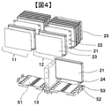
図4および図5は、二次電池モジュール1の製造方法を示す一例である。
4 and 5 are examples showing a method of manufacturing the
図4はバスバーケース51に二次電池2を配列する配列工程を示す図である。
FIG. 4 is a diagram showing an arrangement process of arranging the
まず、バスバーケース51に第一のブロック部材を固定する。
First, the first block member is fixed to the
次にバスバーケース51に設けられた端子挿入孔53の積層方向の最も外側に、二次電池2の正極端子3、負極端子4を挿入する。
Next, the
次に挿入した二次電池2の積層方向内側に、二次電池2を保持するための突起を備えた両面突起絶縁板22を設置する。
Next, a double-sided
続いて、隣接する端子挿入孔53に別の二次電池2を、さらに積層方向内側に両面突起絶縁板22を順々に設置していって二次電池2の積層体を形成する。
Subsequently, another
その後、二次電池2積層体の積層方向両端に片面突起絶縁板23を配置する。この操作をバスバーケース51の全ての端子挿入孔53に対して実施し、第一の電池群11および第二の電池群12を形成する。
After that, the single-sided
なお、本例では隣接する二次電池2のセル外部端子24の極性が逆になるように二次電池2を整列させるが二次電池の接続によってはこれに限られるものではない。また、両面突起絶縁板22と片面突起絶縁板23は例えば、PBT(ポリブチレンテレフタレート)等の樹脂により形成することができる。
In this example, the
バスバーケース51に設けられた端子挿入孔53に二次電池2のセル外部端子24を挿入することで配列することで、二次電池の圧縮前に二次電池を定位置に仮固定することができる。バスバーケース51に正極端子3、負極端子4を挿入せずに二次電池2を並べると、二次電池2の位置決め機構が無いためにセルを所定の位置に並べるのに時間がかかるが、バスバーケース51を二次電池2の配列に使用することで二次電池2を整列させるのに要する時間が減って組立性の向上に寄与する。
By arranging by inserting the cell
図5は、上部固縛板16、下部固縛板17を固定するまでの製造方法の一例を示す。
FIG. 5 shows an example of a manufacturing method for fixing the
図4までに作成途中のモジュールに対して第二のブロック部材14、および第三のブロック部材15をバスバーケース51に固定する。
The
上部固縛板16および下部固縛板17を、第一の電池群11および第二の電池群12に対して接触させ、締結ボルト18にて仮止めする。
The
上部固縛板16および下部固縛板17の幅広面に対して垂直に圧縮荷重を加えて、上部固縛板16と下部固縛板17間の距離が所定の寸法に達したら締結ボルト18を所定トルクで回して固定する。
A compressive load is applied perpendicularly to the wide surfaces of the
その後、それぞれ隣接する二次電池2の正極端子3、負極端子4間を電気的に繋ぐバスバー31、積層方向最も端部側の正極端子3または負極端子4に二次電池モジュール1の外部と二次電池とを電気的に接続する外部接続用のバスバーを設置してレーザー溶接等で固定する。
After that, the
次に、以上のように、バスバーケース51の端子挿入孔52に正極端子3、負極端子4を固定した後に二次電池積層体に圧縮荷重を加えてモジュールを形成する製造方法を用いる場合の二次電池モジュール構造について述べる。
Next, in the case of using the manufacturing method of forming a module by fixing the
図6は、バスバーケース51に形成した端子挿入孔53に二次電池2の正極端子3、負極端子4を挿入し上部固縛板16および下部固縛板17で仮止めした状態(圧縮前)の二次電池モジュール1を、バスバーケース51側から見た図である。
FIG. 6 shows a state in which the
図7は、図6の状態から上部固縛板16および下部固縛板17を所定寸法まで押圧して締結ボルト18にて固定した後の二次電池モジュール1の形状を示した図である。
FIG. 7 is a diagram showing the shape of the
二次電池2は、電池缶内に正極と負極が積層された蓄電要素を有しており、充放電により蓄電要素が膨張収縮する。二次電池2を圧縮した状態で固定することによりこの膨張収縮を抑え、性能を維持することに寄与することができる。二次電池を圧縮した場合、二次電池の圧縮方向の径が変わり、端子同士の位置関係も変化する。
The
図6において、端子(正極端子3または負極端子4)と端子挿入孔53の内壁との二次電池2積層方向の距離(隙間61)は積層方向外側と内側とで異なっている。端子と積層方向外側の内壁との距離に注目すると、積層方向外側では、小さく、積層内側ほど大きくなる。端子と積層方向内側の内壁との距離に注目した場合は、積層方向外側では、大きく、積層方向内側ほど小さくなる。
In FIG. 6, the distance (gap 61) between the terminal (
図7では、二次電池を積層方向に圧縮しているため、内壁と端子との距離に違いが生じている。端子と積層方向外側の内壁との距離(隙間61)に注目すると、積層方向外側では、大きく、積層内側ほど小さくなる。端子と積層方向内側の内壁との距離に注目した場合は、積層方向外側では、小さく、積層方向内側ほど大きくなる。 In FIG. 7, since the secondary battery is compressed in the stacking direction, there is a difference in the distance between the inner wall and the terminal. Focusing on the distance between the terminal and the inner wall on the outer side in the stacking direction (gap 61), it is larger on the outer side in the stacking direction and smaller on the inner side in the stacking direction. When paying attention to the distance between the terminal and the inner wall inside the stacking direction, the distance is smaller on the outside in the stacking direction and larger on the inside in the stacking direction.
図6と図7の違いは、図6の状態から図7の状態にかけて二次電池を積層方向に押圧しことにより隣接する二次電池2の端子どうしのピッチが縮んだことにより生じる。ある二次電池2の端子の積層方向一方側の面から、隣接する二次電池の端子の積層方向一方側の面までのピッチは、圧縮前(図6)をA、圧縮後をBとした場合にA>Bの関係となる。また、このピッチA,Bの変化は、二次電池2の積層方向の厚さの変化によるものであり、二次電池2の積層方向の厚さを押圧前a,押圧後bとした場合a>bを満たす。
The difference between FIGS. 6 and 7 is caused by the fact that the pitch between the terminals of the adjacent
ここで、押圧後のピッチaは完成後の電池群の端子のピッチを測定することにより、また、押圧前ピッチaは仮組み時に二次電池2が接触した状態での端子のピッチより求めることができる。二次電池2の積層方向の厚さは押圧前と押圧後に測定することができ、押圧後に再度押圧を開放することによってもAを求めることができる。
Here, the pitch a after pressing is obtained by measuring the pitch of the terminals of the battery group after completion, and the pitch a before pressing is obtained from the pitch of the terminals in a state where the
このように、二次電池積層体は押圧前と後とでサイズが変わるため、バスバーケース51の端子挿入孔の位置はこれを考慮して設けなければ上述したような製造方法、つまり、バスバーケース51の挿入孔53に二次電池2のセル外部端子24を挿入して位置決めをしてから押圧する製造方法を用いることができない。押圧後のサイズでバスバーケース51における端子挿入孔53の位置を決めてしまった場合、押圧前では上記ピッチが大きいためバスバーケース51の挿入孔53に二次電池2のセル外部端子24を挿入して位置決めをすることができない。
As described above, since the size of the secondary battery laminate changes before and after pressing, the position of the terminal insertion hole of the
図6、図7のように押圧前、後においてもセル外部端子24が端子挿入孔53に収まることで、組み立て性に優れる上記製造方法を用いることができる。具体的には、積層方向の両端に設けられた二次電池のセル外部端子24と端子挿入孔53との間の積層方向外側の隙間の総計の大きさM(積層方向両端側の隙間61を足した大きさ)が以下式(1)を満たす。
M>(A−B)×(N−1) …式(1)
As shown in FIGS. 6 and 7, the cell
M> (AB) × (N-1)… Equation (1)
式(1)において、Aは、二次電池積層体が押圧されていない状態における二次電池の端子の積層方向一方側端部から、隣接する二次電池の端子の積層方向一方側までの長さである(図6,7)。Bは、二次電池積層体を積層方向両側から押圧した状態における、二次電池の端子の積層方向一方側端部から、隣接する二次電池の端子の積層方向一方側までの長さである(図6,7)。A>Bを満たす。Nは、二次電池の積層方向における個数である。ここで、押圧した状態は、例えば二次電池積層体がセルブロック、上部固縛板、下部固縛板等により囲まれて固定された状態である。押圧されていない状態は、例えば、これら固定が外された状態である。 In the formula (1), A is the length from one end in the stacking direction of the terminals of the secondary battery to one side in the stacking direction of the terminals of the adjacent secondary battery when the secondary battery stack is not pressed. That is (Figs. 6 and 7). B is the length from one end of the terminal of the secondary battery in the stacking direction to one side of the terminal of the adjacent secondary battery in the state where the laminated battery of the secondary battery is pressed from both sides in the stacking direction. (Figs. 6 and 7). Satisfy A> B. N is the number of secondary batteries in the stacking direction. Here, the pressed state is, for example, a state in which the secondary battery laminate is surrounded and fixed by a cell block, an upper lashing plate, a lower lashing plate, or the like. The state of not being pressed is, for example, a state in which these fixings are released.
式(1)を満たすことで、上記製造方法を用いることができる。以下、根拠について述べる。 By satisfying the formula (1), the above manufacturing method can be used. The grounds will be described below.
まず、積層方向の末端に設けられた二次電池2の端子と端子挿入孔53との間の積層方向外側の隙間61に注目する。ここで、積層方向全てのセル外部端子24は押圧前、押圧後でもバスバーケース51に設けられた端子挿入孔53に挿入されていることを前提として計算する。各セル外部端子の押圧前後の動きを計算する。二次電池積層体が押圧されることにより、二次電池2あたり(A−B)だけ積層方向に収縮することになる。ここで積層方向の中心(図6,7においては積層方向上から3セル目と4セル目の中間点)を押圧前後で動かない基準点とすると、基準点近傍の3セル目と4セル目のセル外部端子24は(A−B)/2だけ中心側に動くことになる。その外側の2セル目と5セル目のセルのセル外部端子24は(A−B)×3/2だけ中心側に動くことになる。末端の1セル目と6セル目の二次電池2のセル外部端子24は(A−B)×5/2だけ中心側に動くことになる。つまり末端の二次電池2のセル外部端子24の移動量が最も大きい。したがって、最も移動量が大きい末端二次電池のセル外部端子24が押圧前でも押圧後でもバスバーケース51の端子挿入孔53に収まっていることが、その他の二次電池のセル外部端子24が端子挿入孔53に収まっているための必要条件となる。
First, pay attention to the
仮に押圧前に二次電池積層体の末端の二次電池2のセル外部端子24の積層方向外側とバスバーケース51の仕切り部52との隙間が無かったとすると、押圧後には末端の二次電池2は積層方向中央側に(A−B)×5/2だけ移動するため、押圧後の末端二次電池2のセル外部端子24の積層方向外側とバスバーケース51の仕切り部52との隙間61は(A−B)×(5/2)となる。
Assuming that there is no gap between the outside of the cell
同様に反対側の末端二次電池2についても押圧前にセル外部端子24の積層方向外側とバスバーケース51の仕切り部52との隙間が無かったとすると、押圧後にはセル外部端子の外側に(A−B)×(5/2)の隙間が発生する。両側の末端二次電池2の外側の隙間の和をとると、(A−B)×5となる。
Similarly, regarding the terminal
上記は積層方向の中心を押圧前後で動かない基準点としたが、電池群の末端二次電池2を押圧前後で動かない基準点とした場合について述べる。
In the above, the center of the stacking direction is set as a reference point that does not move before and after pressing, but a case where the terminal
このとき末端の二次電池2から1セル分、中心側の二次電池(2セル目)は(A−B)だけ積層方向中心側に動く。同様に3、4、5、6セル目の移動量はそれぞれ(A−B)×2、(A−B)×3、(A−B)×4、(A−B)×5となる。
At this time, the secondary battery (second cell) on the center side moves toward the center side in the stacking direction by one cell from the
押圧前の末端の二次電池2(1セル目、6セル目)のセル外部端子24の積層方向外側とバスバーケース51の仕切り部52との隙間が無かったとすると、押圧後の末端二次電池2のセル外部端子24の積層方向外側とバスバーケース51の仕切り部52との隙間は1セル目は0、6セル目では(A−B)×5となり、両者の和をとると(A−B)×5となり、押圧前後で動かない基準点の場所が電池群中心であったときと同一の値となる。つまり、押圧前後で動かない基準点の場所によらず、押圧後の末端セル21のセル外部端子24の積層方向外側とバスバーケース51の仕切り部52との隙間のモジュール両端での和は(A−B)×5となる。なお、これは電池群を構成するセル数が6セルの場合であるが、これがNセルとなる場合は、同様に両側にある末端二次電池2の外側の隙間の和を取ると、(A−B)×(N−1)となる。
Assuming that there is no gap between the outside of the cell
上記は押圧前に末端二次電池2のセル外部端子24の外側とバスバーケース51の仕切り部52の隙間が無い状態であったが、押圧前に隙間があった場合は、押圧後には、押圧前の隙間に加えて上記の(A−B)×(N−1)の隙間が加わることになる。つまり、バスバーケースの端子挿入孔に二次電池2を固定した後にセル群に圧縮荷重を加えてモジュールを形成した場合、末端二次電池2のセル外部端子の積層方向外側とバスバーケースの仕切り部との間の隙間は(A−B)×(N−1)以上となる。したがって、積層方向の両端に設けられた二次電池のセル外部端子24と端子挿入孔53との間の積層方向外側の隙間の総計の大きさM(積層方向両端側の隙間61を足した大きさ)を(A−B)×(N−1)以上とすることで、図6、図7のように押圧前、後においてもセル外部端子24が端子挿入孔53に収まることでき、上記製造方法を用いることができる構造となる。
In the above, there was no gap between the outside of the cell
次に、末端の二次電池2以外の二次電池2も含めた、セル外部端子24とバスバーケース51の仕切り部52との隙間61の関係を求める。
Next, the relationship of the
図2でバスバーケース51は仕切り部52が等間隔で並び、それぞれの端子挿入孔53の大きさは積層方向に対して略一定である。ここで、仕切り部の厚さをCと置くと、それらの関係はA>C>Bとなる。押圧後の末端の二次電池2のセル外部端子24の外側の隙間61がEの場合、末端より1セル分積層方向中心側の二次電池2のセル外部端子24の外側の隙間61は、E−(C−B)と計算される。さらに積層方向内側の二次電池2の隙間61はE−(C−B)×2となる。Nセル分、積層方向内側に行くと上記の隙間61はE−(C−B)×Nとなる。つまり積層方向内側に行くほどセル外部端子24の積層方向外側の隙間61が小さくなる。また、反対側の末端の二次電池2のセル外部端子24の外側の隙間61がFの場合、上記の議論と同様にして、Nセル分、積層方向内側に行くと上記の隙間61はF−(C−B)×Nとなる。
In FIG. 2, the
このように等ピッチの仕切り部52を持つバスバーケース51を用いると、押圧後のセル外部端子24と仕切り部52の積層方向外側の隙間61は、積層方向によって異なっており、積層方向中心に向かうにつれて一定量ずつ小さくなっていく。逆に、積層方向中心から外側に向かうにつれて一定量ずつ大きくなっていく。
When the
仕切り部52があったとしても、F+EすなわちMを(A−B)×(N−1)以上とすることで、図6、図7のように押圧前、後においてもセル外部端子24が端子挿入孔53に収まることでき、上記製造方法を用いることができる構造となる。
Even if there is a
(実施例2)
実施例1は、端子挿入孔53の積層方向の大きさと間隔を一定に揃えたのに対して、実施例2では端子挿入孔53の積層方向の大きさと間隔を不等とした。
(Example 2)
In Example 1, the size and spacing of the terminal insertion holes 53 in the stacking direction were made constant, whereas in Example 2, the size and spacing of the terminal insertion holes 53 in the stacking direction were unequal.
図8は実施例2におけるバスバーケース51の図である。積層方向に6つ設けられた端子挿入孔53のうちの1つが狭く、幅狭端子挿入孔54となっている。その他の端子挿入孔53は積層方向で同一長さの幅広端子挿入孔55となっている。幅狭端子挿入孔54の積層方向の長さは、セル外部端子24の積層方向の長さと同程度で、端子が入りやすい程度にやや大きい。
FIG. 8 is a diagram of the
図9は、図8のバスバーケース51に形成した幅狭端子挿入孔54および幅広端子挿入孔55に二次電池2のセル外部端子24を挿入し、上部固縛板16および下部固縛板17で仮止めした状態(二次電池の押圧前)の二次電池モジュール1を、バスバーケース51側から見た図である。
In FIG. 9, the cell
図10は、バスバーケース51に形成した幅狭端子挿入孔54および幅広端子挿入孔55に二次電池2のセル外部端子24を挿入し、上部固縛板16および下部固縛板17を所定寸法まで押圧して締結ボルト18にて固定した状態のモジュールをバスバーケース51側から見た図である。
In FIG. 10, the cell
幅狭端子挿入孔54の積層方向の長さはセル外部端子24の大きさ程度のため、押圧の前後で幅狭端子挿入孔54に挿入されたセル外部端子24は動かず、つまり基準セルとなって位置決めされるため、バスバーケース51のがたつきが無くなり、扱いやすくなる利点がある。
Since the length of the narrow
図8のように端子挿入孔53の1つが小さい場合でも、押圧前から押圧後にピッチAがBに変化する場合、先に述べたように基準セルからGセル離れた二次電池2では押圧後には(A−B)×Gだけ積層方向中心側に変位するため、末端の二次電池2のセル外部端子24の積層方向外側の隙間61をモジュール両端にて和を取ると(A−B)×(N−1)以上となる。積層方向両端の二次電池2と端子挿入孔53と端子との距離Mを(A−B)×(N−1)以上とすることで、押圧前、後においてもセル外部端子24が端子挿入孔53に収まることでき、上記製造方法を用いることができる構造となる。
Even if one of the terminal insertion holes 53 is small as shown in FIG. 8, if the pitch A changes to B from before pressing to after pressing, as described above, in the
なお、本実施例のように、端子挿入孔53の積層方向の径が異なるものを1つ用いても良く、積層方向に沿って連続的に径を変えても良い。例えば、端子挿入孔53の積層方向の径を積層方向外側ほど大きくし、内側ほど小さくするようなものでも構わない。
As in this embodiment, one
(実施例3)
実施例3は、二次電池2を1列まとめた二次電池モジュール1の例である。
(Example 3)
The third embodiment is an example of the
図11は実施例3の二次電池モジュール1の図である。
FIG. 11 is a diagram of the
二次電池モジュール1は、6個の二次電池2を1列まとめたモジュールを示す。これまでの実施例では6個の二次電池2を2列まとめたモジュールを示してきたが、1列であっても押圧前にバスバーケース51に設けた仕切り部52の間にセル外部端子24を挿入することで容易に二次電池2を整列させることができる。
The
(実施例4)
実施例4は、実施例3において、バスバーケース51の仕切り部52の数が少なく、隣接する仕切り部52との間に2個のセル外部端子24が挿入される構造である。図12は実施例4の二次電池モジュール1の斜視図である。一つの端子挿入孔53に挿入される2個のセル外部端子24は、後の工程にて共にバスバー31で接続されるものであるため、仕切り部52によって絶縁される必要がない。バスバーケース51の設計自由度を向上させることが可能である。
(Example 4)
In the fourth embodiment, in the third embodiment, the number of
本実施例のように、端子挿入孔53は、二次電池の積層方向で隣り合う二次電池のそれぞれの端子を一組とする区分で設けられていても良く、実施例1,2、3のように端子毎に設けられていてもよい。なお、仕切り部52の数が少ない本実施例のような構造は、実施例1,2のような複数列の二次電池モジュールに対しても用いることができる。
As in the present embodiment, the terminal insertion holes 53 may be provided in a division in which the terminals of the secondary batteries adjacent to each other in the stacking direction of the secondary batteries are set as a set, and the terminal insertion holes 53 may be provided as a set. It may be provided for each terminal as in. The structure as in this embodiment, in which the number of
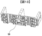
(実施例5)
実施例5は、実施例1において、バスバーケース51と第一のブロック部材13と、第二のブロック部材14、第三のブロック部材15が一体である例である。バスバーケース51、第一のブロック部材13、第二のブロック部材14、第三のブロック部材15は例えば樹脂で形成されることにより一体成型し、ブロック部材付きバスバーケース56とすることができる。一体成型することで、部品数削減、コスト低減に寄与する。また、二次電池2のセル外部端子24を挿入するにあたり、ブロック部材を幅方向のガイドとすることで、さらに組立性を向上させることができる。
(Example 5)
The fifth embodiment is an example in which the
1 二次電池モジュール
2 二次電池
3 正極端子
4 負極端子
11 第一の電池群(二次電池積層体)
12 第二の電池群(二次電池積層体)
13 第一のブロック部材
14 第二のブロック部材
15 第三のブロック部材
16 上部固縛板
17 下部固縛板
18 締結ボルト
22 両面突起絶縁板
23 片面突起絶縁板
24 セル外部端子(正極端子3または負極端子4)
31 バスバー
51 バスバーケース
52 仕切り部
53 端子挿入孔
54 幅狭端子挿入孔
55 幅広端子挿入孔
56 ブロック部材付きバスバーケース
61 隙間
1
12 Second battery group (secondary battery laminate)
13
31
Claims (9)
複数の前記二次電池が前記幅広面を対向させて、一方向側に前記端子を向けて積層された二次電池積層体と、
前記二次電池積層体の前記端子が設けられた側に対向して設けられたバスバーケースと、を有し、
前記バスバーケースは、前記端子に対応した位置にそれぞれ複数の孔を有し、
複数の前記孔は、前記二次電池の積層方向の長さが略同一であり、等ピッチで並んでおり、
前記端子は、前記二次電池の前記積層方向の押圧前後の何れにおいても前記孔に挿入されており、
前記二次電池の積層方向一端側に設けられた前記二次電池と前記孔の内壁との間の隙間のうち前記積層方向外側の隙間Eと、
前記二次電池の積層方向他端側に設けられた前記二次電池と前記孔の内壁との間の隙間のうち前記積層方向外側の隙間Fと、の前記積層方向の和の長さMは、下記式(1)を満たす二次電池モジュール。
M>(A−B)×(N−1) …式(1)
(式(1)において、Aは、二次電池積層体が押圧されていない状態における二次電池の端子の積層方向一方側端部から、隣接する二次電池の端子の積層方向一方側までの長さである。Bは、二次電池積層体を積層方向両側から押圧した状態における、二次電池の端子の積層方向一方側端部から、隣接する二次電池の端子の積層方向一方側までの長さである。A>Bを満たす。Nは、前記二次電池の積層方向における個数である。) A secondary battery having a wide surface and a narrow surface and having terminals provided so as to project from the narrow surface, and a secondary battery.
A secondary battery laminate in which a plurality of the secondary batteries are laminated so that the wide surfaces face each other and the terminals are directed to one direction side.
It has a bus bar case provided so as to face the side of the secondary battery laminate provided with the terminal.
The bus bar case has a plurality of holes at positions corresponding to the terminals.
The plurality of holes have substantially the same length in the stacking direction of the secondary battery, and are arranged at equal pitches.
The terminal is inserted into the hole before and after pressing the secondary battery in the stacking direction.
Of the gaps between the secondary battery and the inner wall of the hole provided on one end side in the stacking direction of the secondary battery, the gap E outside the stacking direction
The total length M in the stacking direction of the gap F outside the stacking direction among the gaps between the secondary battery and the inner wall of the hole provided on the other end side of the stacking direction of the secondary battery is , A secondary battery module that satisfies the following formula (1).
M> (AB) × (N-1)… Equation (1)
(In the formula (1), A is from one end of the terminals of the secondary battery in the stacking direction to one side of the terminals of the adjacent secondary battery in a state where the laminated battery of the secondary battery is not pressed. B is the length from one end of the terminal of the secondary battery in the stacking direction to one side of the terminal of the adjacent secondary battery when the secondary battery laminate is pressed from both sides in the stacking direction. A> B is satisfied. N is the number of the secondary batteries in the stacking direction.)
複数の前記二次電池が前記幅広面を対向させて、一方向側に前記端子を向けて積層された二次電池積層体と、A secondary battery laminate in which a plurality of the secondary batteries are laminated so that the wide surfaces face each other and the terminals are directed to one direction side.
前記二次電池積層体の前記端子が設けられた側に対向して設けられたバスバーケースと、を有し、It has a bus bar case provided so as to face the side of the secondary battery laminate provided with the terminal.
前記バスバーケースは、前記端子に対応した位置にそれぞれ複数の孔を有し、The bus bar case has a plurality of holes at positions corresponding to the terminals.
複数の前記孔のうちの1つの幅狭孔の前記二次電池の積層方向の長さは、前記端子を挿入可能な程度の長さであり、複数の前記孔のうちの前記幅狭孔以外の他の幅広孔の前記積層方向の長さは、前記幅狭孔よりも長く、The length of one of the plurality of holes in the narrow hole in the stacking direction of the secondary battery is such that the terminal can be inserted, and the length of the narrow hole is other than the narrow hole of the plurality of holes. The length of the other wide holes in the stacking direction is longer than that of the narrow holes.
前記幅狭孔に前記端子が挿入された前記二次電池からG個(GはN以下の正整数)だけ離れた前記二次電池と前記幅広孔の内壁との間の隙間のうち前記積層方向外側に設けられた隙間の前記積層方向の長さは(A−B)×G以上であり、The stacking direction in the gap between the secondary battery and the inner wall of the wide hole separated by G (G is a positive integer of N or less) from the secondary battery in which the terminal is inserted into the narrow hole. The length of the gap provided on the outside in the stacking direction is (AB) × G or more.
前記二次電池の積層方向一端側に設けられた前記二次電池と前記孔の内壁との間の隙間のうち前記積層方向外側の隙間Eと、Of the gaps between the secondary battery and the inner wall of the hole provided on one end side in the stacking direction of the secondary battery, the gap E outside the stacking direction
前記二次電池の積層方向他端側に設けられた前記二次電池と前記孔の内壁との間の隙間のうち前記積層方向外側の隙間Fと、の前記積層方向の和の長さMは、下記式(1)を満たす二次電池モジュール。The total length M in the stacking direction of the gap F outside the stacking direction among the gaps between the secondary battery and the inner wall of the hole provided on the other end side of the stacking direction of the secondary battery is , A secondary battery module that satisfies the following formula (1).
M>(A−B)×(N−1) …式(1)M> (AB) × (N-1)… Equation (1)
(上記及び式(1)において、Aは、二次電池積層体が押圧されていない状態における二次電池の端子の積層方向一方側端部から、隣接する二次電池の端子の積層方向一方側までの長さである。Bは、二次電池積層体を積層方向両側から押圧した状態における、二次電池の端子の積層方向一方側端部から、隣接する二次電池の端子の積層方向一方側までの長さである。A>Bを満たす。Nは、前記二次電池の積層方向における個数である。)(In the above and in the formula (1), A is one side in the stacking direction of the terminals of the adjacent secondary battery from one end in the stacking direction of the terminals of the secondary battery when the secondary battery stack is not pressed. B is the stacking direction of the terminals of the secondary battery from one end in the stacking direction of the secondary battery when the secondary battery laminate is pressed from both sides in the stacking direction. The length to the side. A> B is satisfied. N is the number of the secondary batteries in the stacking direction.)
前記孔は、少なくとも前記積層方向で隣り合う二次電池のそれぞれの端子を一組とする区分で設けられている二次電池モジュール。 In claim 1 or 2 ,
The hole is a secondary battery module provided in a section in which terminals of adjacent secondary batteries are set as a set at least in the stacking direction.
前記隙間の大きさは、前記積層方向の内側から前記積層方向外側に向かって大きくなる二次電池モジュール。 In claim 1 ,
A secondary battery module in which the size of the gap increases from the inside in the stacking direction toward the outside in the stacking direction.
前記二次電池積層体の前記積層方向の両端側には、一組の固縛版が設けられ、
前記一組の固縛版は、前記二次電池の幅狭面に対向して設けられたセルブロックを介して接続され、
前記二次電池積層体は、前記積層方向に押圧された状態で固縛された二次電池モジュール。 In claim 2 or 4 ,
A set of lashing plates are provided on both ends of the secondary battery laminate in the stacking direction.
The set of lashing plates are connected via a cell block provided so as to face the narrow surface of the secondary battery.
The secondary battery stack is a secondary battery module that is fixed in a state of being pressed in the stacking direction.
前記二次電池積層体は複数列設けられ、
前記複数の二次電池積層体の間には、前記セルブロックが設けられた二次電池モジュール。 In claim 5 ,
The secondary battery laminate is provided in a plurality of rows, and the secondary battery laminate is provided in a plurality of rows.
A secondary battery module in which the cell block is provided between the plurality of secondary battery laminates.
前記セルブロックと、前記バスバーケースは、一体である二次電池モジュール。 In claim 6 ,
The cell block and the bus bar case are integrated secondary battery modules.
複数の前記二次電池が前記幅広面を対向させて、一方向側に前記端子を向けて積層された二次電池積層体と、
前記二次電池積層体の前記端子が設けられた側に対向して設けられたバスバーケースと、を有する二次電池モジュール製造方法であって、
複数の前記二次電池を、前記バスバーケースに設けられた孔に前記二次電池の前記端子を挿入して配列する配列工程と、
前記配列工程の後に、複数の前記二次電池を積層方向に押圧する押圧工程と、を含み、
前記バスバーケースは、前記端子に対応した位置にそれぞれ複数の孔を有し、
複数の前記孔は、前記二次電池の積層方向の長さが略同一であり、等ピッチで並んでおり、
前記端子は、前記二次電池の前記積層方向の押圧前後の何れにおいても前記孔に挿入されており、
前記二次電池の積層方向一端側に設けられた前記二次電池と前記孔の内壁との間の隙間のうち前記積層方向外側の隙間Eと、
前記二次電池の積層方向他端側に設けられた前記二次電池と前記孔の内壁との間の隙間のうち前記積層方向外側の隙間Fと、の前記積層方向の和の長さMは、下記式(1)を満たす二次電池モジュール製造方法。
M>(A−B)×(N−1) …式(1)
(式(1)において、Aは、二次電池積層体が押圧されていない状態における二次電池の端子の積層方向一方側端部から、隣接する二次電池の端子の積層方向一方側までの長さである。Bは、二次電池積層体を積層方向両側から押圧した状態における、二次電池の端子の積層方向一方側端部から、隣接する二次電池の端子の積層方向一方側までの長さである。A>Bを満たす。Nは、前記二次電池の積層方向における個数である。) A secondary battery having a wide surface and a narrow surface and having terminals provided so as to project from the narrow surface, and a secondary battery.
A secondary battery laminate in which a plurality of the secondary batteries are laminated so that the wide surfaces face each other and the terminals are directed to one direction side.
A method for manufacturing a secondary battery module, comprising a bus bar case provided so as to face the side of the secondary battery laminate provided with the terminal.
An arrangement step of arranging a plurality of the secondary batteries by inserting the terminals of the secondary batteries into holes provided in the bus bar case.
After the arrangement step, a pressing step of pressing the plurality of the secondary batteries in the stacking direction is included .
The bus bar case has a plurality of holes at positions corresponding to the terminals.
The plurality of holes have substantially the same length in the stacking direction of the secondary battery, and are arranged at equal pitches.
The terminal is inserted into the hole before and after pressing the secondary battery in the stacking direction.
Of the gaps between the secondary battery and the inner wall of the hole provided on one end side in the stacking direction of the secondary battery, the gap E outside the stacking direction
The total length M in the stacking direction of the gap F outside the stacking direction among the gaps between the secondary battery and the inner wall of the hole provided on the other end side of the stacking direction of the secondary battery is , A method for manufacturing a secondary battery module that satisfies the following formula (1).
M> (AB) × (N-1)… Equation (1)
(In the formula (1), A is from one end of the terminals of the secondary battery in the stacking direction to one side of the terminals of the adjacent secondary battery in a state where the laminated battery of the secondary battery is not pressed. B is the length from one end of the terminal of the secondary battery in the stacking direction to one side of the terminal of the adjacent secondary battery when the secondary battery laminate is pressed from both sides in the stacking direction. A> B is satisfied. N is the number of the secondary batteries in the stacking direction.)
複数の前記二次電池が前記幅広面を対向させて、一方向側に前記端子を向けて積層された二次電池積層体と、A secondary battery laminate in which a plurality of the secondary batteries are laminated so that the wide surfaces face each other and the terminals are directed to one direction side.
前記二次電池積層体の前記端子が設けられた側に対向して設けられたバスバーケースと、を有する二次電池モジュール製造方法であって、A method for manufacturing a secondary battery module, comprising a bus bar case provided so as to face the side of the secondary battery laminate provided with the terminal.
前記バスバーケースは、前記端子に対応した位置にそれぞれ複数の孔を有し、The bus bar case has a plurality of holes at positions corresponding to the terminals.
複数の前記孔のうちの1つの幅狭孔の前記二次電池の積層方向の長さは、前記端子を挿入可能な程度の長さであり、複数の前記孔のうちの前記幅狭孔以外の他の幅広孔の前記積層方向の長さは、前記幅狭孔よりも長く、The length of one of the plurality of holes in the narrow hole in the stacking direction of the secondary battery is such that the terminal can be inserted, and the length of the narrow hole is other than the narrow hole of the plurality of holes. The length of the other wide holes in the stacking direction is longer than that of the narrow holes.
前記幅狭孔に前記端子が挿入された前記二次電池からG個(GはN以下の正整数)だけ離れた前記二次電池と前記幅広孔の内壁との間の隙間のうち前記積層方向外側に設けられた隙間の前記積層方向の長さは(A−B)×G以上であり、The stacking direction in the gap between the secondary battery and the inner wall of the wide hole separated by G (G is a positive integer of N or less) from the secondary battery in which the terminal is inserted into the narrow hole. The length of the gap provided on the outside in the stacking direction is (AB) × G or more.
前記二次電池の積層方向一端側に設けられた前記二次電池と前記孔の内壁との間の隙間のうち前記積層方向外側の隙間Eと、Of the gaps between the secondary battery and the inner wall of the hole provided on one end side in the stacking direction of the secondary battery, the gap E outside the stacking direction
前記二次電池の積層方向他端側に設けられた前記二次電池と前記孔の内壁との間の隙間のうち前記積層方向外側の隙間Fと、の前記積層方向の和の長さMは、下記式(1)を満たす二次電池モジュール製造方法。The total length M in the stacking direction of the gap F outside the stacking direction among the gaps between the secondary battery and the inner wall of the hole provided on the other end side of the stacking direction of the secondary battery is , A method for manufacturing a secondary battery module that satisfies the following formula (1).
M>(A−B)×(N−1) …式(1)M> (AB) × (N-1)… Equation (1)
(上記及び式(1)において、Aは、二次電池積層体が押圧されていない状態における二次電池の端子の積層方向一方側端部から、隣接する二次電池の端子の積層方向一方側までの長さである。Bは、二次電池積層体を積層方向両側から押圧した状態における、二次電池の端子の積層方向一方側端部から、隣接する二次電池の端子の積層方向一方側までの長さである。A>Bを満たす。Nは、前記二次電池の積層方向における個数である。)(In the above and in the formula (1), A is one side in the stacking direction of the terminals of the adjacent secondary battery from one end in the stacking direction of the terminals of the secondary battery when the secondary battery stack is not pressed. B is the stacking direction of the terminals of the secondary battery from one end in the stacking direction of the secondary battery when the secondary battery laminate is pressed from both sides in the stacking direction. The length to the side. A> B is satisfied. N is the number of the secondary batteries in the stacking direction.)
Priority Applications (5)
| Application Number | Priority Date | Filing Date | Title |
|---|---|---|---|
| JP2018031500A JP6979372B2 (en) | 2018-02-26 | 2018-02-26 | Battery module |
| PCT/JP2019/002177 WO2019163381A1 (en) | 2018-02-26 | 2019-01-24 | Battery module |
| EP19757454.4A EP3764419A4 (en) | 2018-02-26 | 2019-01-24 | Battery module |
| CN201980006931.3A CN111742423B (en) | 2018-02-26 | 2019-01-24 | Battery module |
| US16/958,414 US11394088B2 (en) | 2018-02-26 | 2019-01-24 | Battery module |
Applications Claiming Priority (1)
| Application Number | Priority Date | Filing Date | Title |
|---|---|---|---|
| JP2018031500A JP6979372B2 (en) | 2018-02-26 | 2018-02-26 | Battery module |
Publications (2)
| Publication Number | Publication Date |
|---|---|
| JP2019149227A JP2019149227A (en) | 2019-09-05 |
| JP6979372B2 true JP6979372B2 (en) | 2021-12-15 |
Family
ID=67687638
Family Applications (1)
| Application Number | Title | Priority Date | Filing Date |
|---|---|---|---|
| JP2018031500A Active JP6979372B2 (en) | 2018-02-26 | 2018-02-26 | Battery module |
Country Status (5)
| Country | Link |
|---|---|
| US (1) | US11394088B2 (en) |
| EP (1) | EP3764419A4 (en) |
| JP (1) | JP6979372B2 (en) |
| CN (1) | CN111742423B (en) |
| WO (1) | WO2019163381A1 (en) |
Families Citing this family (4)
| Publication number | Priority date | Publication date | Assignee | Title |
|---|---|---|---|---|
| JP7097343B2 (en) * | 2019-11-15 | 2022-07-07 | 本田技研工業株式会社 | Power storage device |
| KR20220001228A (en) * | 2020-06-29 | 2022-01-05 | 주식회사 엘지에너지솔루션 | Battery Module Having Barrier and Insulation Layer For Fire Suppression |
| CN113113713B (en) * | 2021-04-08 | 2022-07-08 | 中国第一汽车股份有限公司 | Power battery assembly and vehicle |
| DE102022106987A1 (en) | 2022-03-24 | 2023-09-28 | Volkswagen Aktiengesellschaft | Battery with multi-sided cooling, drive system and motor vehicle |
Family Cites Families (10)
| Publication number | Priority date | Publication date | Assignee | Title |
|---|---|---|---|---|
| KR101201747B1 (en) * | 2010-05-24 | 2012-11-15 | 에스비리모티브 주식회사 | Battery module |
| JP6184959B2 (en) * | 2012-08-09 | 2017-08-23 | 三洋電機株式会社 | Battery system, vehicle including battery system, and power storage device |
| WO2014024424A1 (en) * | 2012-08-09 | 2014-02-13 | 三洋電機株式会社 | Method for producing battery pack |
| WO2014034079A1 (en) * | 2012-08-30 | 2014-03-06 | 三洋電機株式会社 | Power source device, vehicle provided with power source device, and power storage device |
| JP2015011919A (en) * | 2013-07-01 | 2015-01-19 | 三洋電機株式会社 | Power unit |
| JP6127836B2 (en) * | 2013-08-29 | 2017-05-17 | 株式会社Gsユアサ | Power supply module and insulation plate |
| JP6247486B2 (en) * | 2013-09-24 | 2017-12-13 | 日立オートモティブシステムズ株式会社 | Assembled battery |
| JP6306431B2 (en) * | 2014-05-21 | 2018-04-04 | 日立オートモティブシステムズ株式会社 | Battery module |
| JP6606818B2 (en) * | 2014-10-17 | 2019-11-20 | 住友電気工業株式会社 | Power storage device module |
| JP2017130312A (en) * | 2016-01-19 | 2017-07-27 | カルソニックカンセイ株式会社 | Battery pack |
-
2018
- 2018-02-26 JP JP2018031500A patent/JP6979372B2/en active Active
-
2019
- 2019-01-24 EP EP19757454.4A patent/EP3764419A4/en active Pending
- 2019-01-24 CN CN201980006931.3A patent/CN111742423B/en active Active
- 2019-01-24 WO PCT/JP2019/002177 patent/WO2019163381A1/en unknown
- 2019-01-24 US US16/958,414 patent/US11394088B2/en active Active
Also Published As
| Publication number | Publication date |
|---|---|
| WO2019163381A1 (en) | 2019-08-29 |
| US20200350548A1 (en) | 2020-11-05 |
| CN111742423B (en) | 2023-01-03 |
| US11394088B2 (en) | 2022-07-19 |
| EP3764419A4 (en) | 2021-11-24 |
| CN111742423A (en) | 2020-10-02 |
| EP3764419A1 (en) | 2021-01-13 |
| JP2019149227A (en) | 2019-09-05 |
Similar Documents
| Publication | Publication Date | Title |
|---|---|---|
| JP6979372B2 (en) | Battery module | |
| KR100921346B1 (en) | Mid-Large Battery Module and Battery Module Assembly | |
| JP6940272B2 (en) | Battery submodule carriers, battery submodules, battery systems and automobiles | |
| EP2330657B1 (en) | Battery module and battery pack including the same | |
| RU2648243C1 (en) | Accumulator battery | |
| JP5259602B2 (en) | Cell module cartridge and medium-to-large battery module including the same | |
| KR101480385B1 (en) | Battery Module Assembly Having Bus Bar Assembly on Front and Battery Pack Employed with the Same | |
| JP5357853B2 (en) | Battery module | |
| JP7300678B2 (en) | Combined Battery Modules and Combined Battery Packs | |
| US8557428B2 (en) | Battery module and battery pack including the same | |
| KR102345081B1 (en) | Battery module with cover assembly | |
| JP7117609B2 (en) | battery module | |
| EP3787088A1 (en) | Battery pack | |
| KR100894407B1 (en) | Cell-Module Cartridge and Cell-Module Including the Same | |
| JP6679717B2 (en) | Terminal device for energy storage device | |
| US20170033339A1 (en) | Electricity storage system | |
| WO2018142809A1 (en) | Power storage device | |
| JP6636035B2 (en) | Battery compression inhibitor and battery module including the same | |
| WO2020235279A1 (en) | Bus bar plate | |
| JP7307069B2 (en) | Fixing structure of battery module | |
| JP6973180B2 (en) | Battery pack | |
| WO2020008681A1 (en) | Secondary battery module | |
| JP6031388B2 (en) | Assembled battery | |
| JP2010205672A (en) | Battery pack | |
| JP5434161B2 (en) | Assembled battery |
Legal Events
| Date | Code | Title | Description |
|---|---|---|---|
| A521 | Request for written amendment filed |
Free format text: JAPANESE INTERMEDIATE CODE: A523 Effective date: 20180228 |
|
| RD02 | Notification of acceptance of power of attorney |
Free format text: JAPANESE INTERMEDIATE CODE: A7422 Effective date: 20190222 |
|
| RD04 | Notification of resignation of power of attorney |
Free format text: JAPANESE INTERMEDIATE CODE: A7424 Effective date: 20190306 |
|
| A711 | Notification of change in applicant |
Free format text: JAPANESE INTERMEDIATE CODE: A712 Effective date: 20200227 |
|
| A521 | Request for written amendment filed |
Free format text: JAPANESE INTERMEDIATE CODE: A523 Effective date: 20200409 |
|
| A521 | Request for written amendment filed |
Free format text: JAPANESE INTERMEDIATE CODE: A523 Effective date: 20200416 |
|
| A521 | Request for written amendment filed |
Free format text: JAPANESE INTERMEDIATE CODE: A523 Effective date: 20200703 |
|
| A621 | Written request for application examination |
Free format text: JAPANESE INTERMEDIATE CODE: A621 Effective date: 20200708 |
|
| A131 | Notification of reasons for refusal |
Free format text: JAPANESE INTERMEDIATE CODE: A131 Effective date: 20210706 |
|
| A601 | Written request for extension of time |
Free format text: JAPANESE INTERMEDIATE CODE: A601 Effective date: 20210903 |
|
| A521 | Request for written amendment filed |
Free format text: JAPANESE INTERMEDIATE CODE: A523 Effective date: 20211020 |
|
| TRDD | Decision of grant or rejection written | ||
| A01 | Written decision to grant a patent or to grant a registration (utility model) |
Free format text: JAPANESE INTERMEDIATE CODE: A01 Effective date: 20211109 |
|
| A61 | First payment of annual fees (during grant procedure) |
Free format text: JAPANESE INTERMEDIATE CODE: A61 Effective date: 20211115 |
|
| R150 | Certificate of patent or registration of utility model |
Ref document number: 6979372 Country of ref document: JP Free format text: JAPANESE INTERMEDIATE CODE: R150 |