JP6979255B2 - Vehicle guidance system - Google Patents
Vehicle guidance system Download PDFInfo
- Publication number
- JP6979255B2 JP6979255B2 JP2021003822A JP2021003822A JP6979255B2 JP 6979255 B2 JP6979255 B2 JP 6979255B2 JP 2021003822 A JP2021003822 A JP 2021003822A JP 2021003822 A JP2021003822 A JP 2021003822A JP 6979255 B2 JP6979255 B2 JP 6979255B2
- Authority
- JP
- Japan
- Prior art keywords
- vehicle
- lane
- barrier
- tollhouse
- detection device
- Prior art date
- Legal status (The legal status is an assumption and is not a legal conclusion. Google has not performed a legal analysis and makes no representation as to the accuracy of the status listed.)
- Active
Links
Images


Description
本発明は車両誘導システムに関し、更に具体的には有料道路の出入口に設置されたETC車用出入口に利用される車両を安全に誘導する車両誘導システムに関する。 The present invention relates to a vehicle guidance system, and more specifically, to a vehicle guidance system for safely guiding a vehicle used at an entrance / exit for an ETC vehicle installed at an entrance / exit of a toll road.
近年、有料道路の料金所にETCシステム(Electronic Toll Collection System:ノンストップ料金自動支払いシステム)が設置されるようになってきた。図1に示すように、ETCシステムは、料金所ゲートに設置した路側アンテナ3,5と、車両14に装着した車載器20との間で無線通信を用いて自動的に通行料金の決済を行ない、料金所をノンストップで通行することができるシステムである。ETCシステムは、基本的には、車両14のダッシュボード上などに設置され、料金計算に必要な情報の通信を行なう無線装置である車載器20と、それに挿入して使われる、料金支払者の契約情報が記録されているICカード(ETCカード)21と、料金所の車線(レーン)上に設置され、車載器20と無線通信を行なう路側アンテナ(ETC路側無線装置)3,5等で構成されている。この内、車載器20は民間企業がユーザに向けて販売し、ETCカード21はクレジット会社がユーザに貸与し、路側アンテナ3,5は有料道路事業者が設置している。
In recent years, ETC systems (Electronic Toll Collection System) have been installed at tollhouses on toll roads. As shown in FIG. 1, the ETC system automatically settles tolls using wireless communication between the
図2に示すように、多くの有料道路で使用される入口発券方式においては、入口料金所で、路側アンテナ3,5から車載器20に入口情報を無線送信し、有料道路7を走行後、出口料金所で、車載器20から路側アンテナ3,5に入口情報を無線送信し、別途備える料金計算コンピュータで料金計算を行なって、その料金情報を路側アンテナ3,5から車載器20に向けて無線送信している。都市内高速道路のような均一料金の単純徴収方式では、入口から出口までの間の少なくとも1カ所に、このようなETCが設置されていればよい。なお、路側アンテナ3,5は1本又は2本以上であってよい。
As shown in FIG. 2, in the entrance ticketing method used on many toll roads, entrance information is wirelessly transmitted from the
ETCのメリットは、料金所での渋滞の解消、料金所での停車・発車の減少による騒音の軽減・排気ガスの削減による環境改善、キャッシュレス化に伴う利便性・管理費の削減等、幅広い効果が期待されている。
この先行出願では、有料道路から一般道路に出る際の料金徴収に関する技術を開示しており(段落0036)、無線ICカード用センサー14と無線ICカードとの間で料金徴収が行なわれている。
This prior application discloses a technique for collecting tolls when going out from a toll road to a general road (paragraph 0036), and tolls are collected between the
しかし、現時点では全車両がETCシステム対応車ではないので、有料道路の料金所のレーンには、「ETC専用」と表示されたETC車専用レーンと、「ETC一般」と表示されたETC車も一般車も混在して通れるレーンと、「一般」と表示されたETCシステムを利用出来ないレーンとが混在している。このため、一般車が誤ってETC車専用レーンに進入する場合が起こり得る。なお、この出願書類では、「ETC車」とは、ETCによる料金徴収が可能な車両をいい、「一般車」とは、ETCシステムを利用出来ない車両を言う。 However, at the moment, not all vehicles are ETC system compatible vehicles, so in the lanes of tollhouses on toll roads, there are also ETC vehicle exclusive lanes labeled "ETC exclusive" and ETC vehicles labeled "ETC general". There are lanes where general vehicles can pass together and lanes where the ETC system labeled "general" cannot be used. Therefore, a general vehicle may accidentally enter the ETC vehicle dedicated lane. In this application document, the "ETC vehicle" means a vehicle that can collect charges by ETC, and the "general vehicle" means a vehicle that cannot use the ETC system.
更に、ETC車であっても、その車載器が路側アンテナと正常通信が出来ない場合も起こり得る。例えば、車載器に対するETCカードの未挿入、不完全挿入、直前挿入等の場合である。 Further, even in the case of an ETC vehicle, there may be a case where the on-board unit cannot normally communicate with the roadside antenna. For example, the ETC card is not inserted into the vehicle-mounted device, is incompletely inserted, is inserted immediately before, or the like.
このような場合、開閉バーが下りて進行出来なくなるので、車両を止めてインターホンで係員を呼び出す必要がある。これにより、料金所の渋滞が助長され、ETCの本来の目的に沿わなくなる。また、開閉バーが下りて通行を止められた車両が、レーンからバック走行をして出ようとすると、後続の車両と衝突するおそれもあり、非常に危険である。 In such a case, the open / close bar goes down and it becomes impossible to proceed, so it is necessary to stop the vehicle and call the staff with the intercom. As a result, traffic congestion at the tollhouse is promoted, and the original purpose of ETC is not met. In addition, if a vehicle that has been blocked from passing by the opening / closing bar descending and tries to drive backward from the lane, it may collide with a following vehicle, which is extremely dangerous.
しかしながら、上述の特許文献1に於いては、ETCシステムを利用した車両誘導システムにおける、後述するような安全な車両誘導システムを提供することに関しては、何等言及していない。 However, in the above-mentioned Patent Document 1, there is no mention of providing a safe vehicle guidance system as described later in a vehicle guidance system using an ETC system.
従って、本発明は、一般車がETC車用出入口に進入した場合又はETC車に対してETCシステムが正常に動作しない場合(路側アンテナと車載器の間で通信不能・不可)であっても、車両を安全に誘導する車両誘導システムを提供することを目的とする。 Therefore, according to the present invention, even when a general vehicle enters the entrance / exit for an ETC vehicle or the ETC system does not operate normally for an ETC vehicle (communication between the roadside antenna and the on-board unit is impossible / impossible). It is an object of the present invention to provide a vehicle guidance system for safely guiding a vehicle.
更に本発明は、ETCシステムを利用した車両誘導システムにおいて、例えば、逆走車の走行を許さず、或いは先行車と後続車の衝突を回避し得る、安全な車両誘導システムを提供することを目的とする。 Further, it is an object of the present invention to provide a safe vehicle guidance system in a vehicle guidance system using an ETC system, for example, which does not allow traveling of a reverse vehicle or can avoid a collision between a preceding vehicle and a following vehicle. And.
上記目的に鑑みて、本発明に係る車両誘導システムは、一般道路と有料道路との間の料金所にETC車用レーンを有するインターチェンジに利用される車両誘導システムであって、路側アンテナと車載器と間で通信不能又は通信不可が発生したとき、車両が前記ETC車用レーンから離脱しえる手段を設けたことを特徴とする。 In view of the above object, the vehicle guidance system according to the present invention is a vehicle guidance system used for an interchange having an ETC vehicle lane at a tollhouse between a general road and a toll road, and is a roadside antenna and an on-board unit. It is characterized in that a means for allowing the vehicle to leave the ETC vehicle lane is provided when communication failure or communication failure occurs between the vehicle and the vehicle.
更に、上述の車両誘導システムにおいて、前記ETC車用レーンから離脱しえる手段は、前記ETC車用レーンから分岐して前記車両が前記料金所へ再進入するレーン又は一般者用レーンへ誘導されるレーンとすることができる。 Further, in the vehicle guidance system described above, the means capable of leaving the ETC vehicle lane is guided from the ETC vehicle lane to the lane where the vehicle re-enters the tollhouse or the general public lane. It can be a lane.
更に、上述の車両誘導システムにおいて、前記路側アンテナは、車載器との間で無線通信可能か否かを判定するためのゲート前アンテナと入口情報及び料金情報の送受信を行なうETCアンテナとを有するようにすることもできる。 Further, in the vehicle guidance system described above, the roadside antenna has an antenna in front of the gate for determining whether or not wireless communication is possible with the vehicle-mounted device, and an ETC antenna for transmitting and receiving entrance information and charge information. It can also be.
更に、上述の車両誘導システムにおいて、前記システムは、遮断機、第1の車両検知装置、ゲート前アンテナ、第2の車両検知装置、誘導手段、第3の車両検知装置、第4の車両検知装置及びETCゲートを有し、前記第1の車両検知装置が車両の進入を検知すると、前記遮断機を閉じて後続車との間を一定の間隔を空けるようにし、前記第2の車両検知装置が進入車両を検知すると、車両がゲート前アンテナを通過したことを確認して、このタイミングで通信可能又は通信不能・不可のいずれであるかを判定し、前記第3又は第4の車両検知装置が進入車両を検知すると、後続車のために前記遮断機を開くようにすることもできる。 Further, in the above-mentioned vehicle guidance system, the system includes a breaker, a first vehicle detection device, a gate front antenna, a second vehicle detection device, a guidance means, a third vehicle detection device, and a fourth vehicle detection device. And having an ETC gate, when the first vehicle detection device detects the approach of a vehicle, the breaker is closed so as to leave a certain distance from the following vehicle, and the second vehicle detection device When an approaching vehicle is detected, it is confirmed that the vehicle has passed the antenna in front of the gate, and at this timing, it is determined whether communication is possible, communication is impossible, or impossible, and the third or fourth vehicle detection device is used. When an approaching vehicle is detected, the breaker can be opened for the following vehicle.
更に、上述の車両誘導システムにおいて、少なくとも1つの誘導装置を有し、前記ゲート前アンテナが車載器との間で通信可能又は通信不可・不能と判定したとき、その判定結果に基づいて前記誘導装置により車両を所定の誘導先に誘導するようにすることもできる。 Further, in the above-mentioned vehicle guidance system, when it has at least one guidance device and it is determined that the antenna in front of the gate can communicate with the vehicle-mounted device or communication is impossible / impossible, the guidance device is based on the determination result. It is also possible to guide the vehicle to a predetermined guidance destination.
更に、本発明に係る車両誘導システムは、ETC車載器搭載車が一般道路と有料道路との出入りをする時に、ETC車専用出入口から出入りをする車両を誘導するシステムであって、一般道路と有料道路との出入りをする車両を検知する検知手段と、車両に搭載されたETC車載器とデータを通信する通信手段と、前記通信手段によって受信したデータを認識して、ETCによる料金徴収が可能か判定する判定手段と、前記判定手段により判定した結果に従って、ETCによる料金徴収が可能な車両を、ETCゲートを通って一般道路から有料道路へ入る、または有料道路から一般道路へ出るルートへ誘導し、ETCによる料金徴収が不可能な車両を、再度出入口手前へ戻るルート又は一般車用出入口へ誘導する誘導手段を備え、前記検知手段により車両の進入が検知された場合、遮断機を下ろすことにより、進入した車両のバック走行と後続の車両の進入を防ぐことを特徴とする。 Further, the vehicle guidance system according to the present invention is a system for guiding a vehicle entering and exiting from an ETC vehicle exclusive entrance and exit when a vehicle equipped with an ETC in-vehicle device enters and exits a general road and a toll road, and is a system for guiding the vehicle entering and exiting from the general road and the toll road. Is it possible to collect charges by ETC by recognizing the detection means that detects vehicles entering and exiting the road, the communication means that communicates data with the ETC in-vehicle device mounted on the vehicle, and the data received by the communication means? According to the determination means for determination and the result of determination by the determination means, a vehicle capable of collecting tolls by ETC is guided to a route from a general road to a toll road or from a toll road to a general road through an ETC gate. , Equipped with a guidance means to guide vehicles that cannot be charged by ETC to the route returning to the front of the doorway or the doorway for general vehicles, and when the detection means detects the entry of the vehicle, the breaker is lowered. It is characterized by preventing the back running of the vehicle that has entered and the entry of the following vehicle.
更に、上述の車両誘導システムを有料道路料金所、サービスエリア又はパーキングエリアに設置することもできる。 Further, the vehicle guidance system described above can be installed in a toll road tollhouse, a service area or a parking area.
更に、上述の車両誘導システムを、少なくとも有料駐車場、有料洗車場及びドライブインシアターを含む有料エリアに設置することもできる。 Further, the vehicle guidance system described above can be installed in a toll area including at least a toll parking lot, a toll car wash and a drive-in theater.
更に、本発明に係る車両誘導システムは、一般道路と有料道路との間の料金所にETC車用レーンを有するインターチェンジに利用される車両誘導システムであって、前記ETC車用レーンの途中から分岐する、路側アンテナと車載器との間で通信不能又は通信不可が発生したときに車両を前記ETC車用レーンから離脱させるためのレーンを設け、前記ETC車用レーンから離脱させるためのレーンは、前記車両を前記料金所へ再進入させるレーン又は一般車用レーンへ誘導するレーンであり、前記分岐する地点から先の前記ETC車用レーンの部分及び前記離脱レーンの部分に対して、別の不正車両の逆進入を防止する閉鎖区間を夫々設けている。 Further, the vehicle guidance system according to the present invention is a vehicle guidance system used for an interchange having an ETC vehicle lane at a toll station between a general road and a toll road, and branches from the middle of the ETC vehicle lane. The lane for separating the vehicle from the ETC vehicle lane when communication failure or communication failure occurs between the roadside antenna and the in-vehicle device is provided, and the lane for disconnecting from the ETC vehicle lane is provided. It is a lane that guides the vehicle to the toll booth or a lane for general vehicles, and another fraudulent activity is made with respect to the portion of the ETC vehicle lane and the portion of the departure lane beyond the branching point. Each has a closed section to prevent the vehicle from entering backwards.
更に、上述の車両誘導システムにおいて、前記路側アンテナは、車載器との間で無線通信可能か否かを判定するためのゲート前アンテナと入口情報及び料金情報の送受信を行なうETCアンテナとを有することもできる。 Further, in the vehicle guidance system described above, the roadside antenna has a front-gate antenna for determining whether or not wireless communication is possible with the vehicle-mounted device, and an ETC antenna for transmitting and receiving entrance information and charge information. You can also.
更に、上述の車両誘導システムにおいて、前記システムは、第1の遮断機、第1の車両検知装置、ゲート前アンテナ、第2の車両検知装置、閉鎖区間を作るための遮断機を含む誘導手段を有しており、前記分岐する地点から先の、前記ETC車用レーンに第1の閉鎖区間センサーを有し、前記分岐する地点から先の、前記ETC車用レーンの第1の閉鎖区間に、第3の車両検知装置、ETCゲート、第2の遮断機及を有し、前記第1の閉鎖区間の先に第4の車両検知装置を有し、また前記分岐する地点から先の、前記離脱レーンに第2の閉鎖区間センサーを有し、前記離脱レーンの第2の閉鎖区間に、第5の車両検知装置、第3の遮断機を有し、前記第2の閉鎖区間の先に第6の車両検知装置を有し、前記第1の車両検知装置が車両の進入を検知すると、前記第1の遮断機を閉じて後続車との間を区切るようにし、前記第2の車両検知装置が進入車両を検知すると、車両がゲート前アンテナを通過したことを確認して、このタイミングで通信可能又は通信不能・不可のいずれであるかを判定し、前記閉鎖区間において車両検知装置が進入車両を検知すると、誘導手段の遮断機を閉じ、前記閉鎖区間の先に備えられた車両検知装置が車両の通過を検知すると閉鎖区間出口の遮断機を閉じることによって、別の不正車両が閉鎖区間の出口側から逆進入することを防止し、万一、別の不正車両が閉鎖区間を出る車両とすれ違いに逆進入した場合でも、閉鎖区間センサーが閉鎖区間に車両がいると判定すると、監視センターへ通報する等の処理を行ない、閉鎖区間センサーが閉鎖区間に車両がいないと判定すると、後続車のために第1の遮断機を開くようにすることもできる。 Further, in the vehicle guidance system described above, the system includes a first breaker, a first vehicle detection device, an antenna in front of the gate, a second vehicle detection device, and a guidance means including a breaker for creating a closed section. It has a first closed section sensor in the ETC vehicle lane ahead of the branch point, and has a first closed section in the ETC vehicle lane ahead of the branch point. It has a third vehicle detection device, an ETC gate, a second breaker, a fourth vehicle detection device ahead of the first closed section, and the departure from the branch point. The lane has a second closed section sensor, the second closed section of the departure lane has a fifth vehicle detection device, a third breaker, and a sixth closed section is ahead of the second closed section. When the first vehicle detection device detects the approach of a vehicle, the first vehicle detection device is closed to separate the vehicle from the following vehicle, and the second vehicle detection device is used. When an approaching vehicle is detected, it is confirmed that the vehicle has passed the antenna in front of the gate, and at this timing it is determined whether communication is possible or communication is impossible or impossible, and the vehicle detection device detects the approaching vehicle in the closed section. When detected, the breaker of the guiding means is closed, and when the vehicle detection device provided at the end of the closed section detects the passage of the vehicle, the breaker at the exit of the closed section is closed, so that another illegal vehicle exits the closed section. Prevents reverse entry from the side, and even if another illegal vehicle enters backward by passing a vehicle leaving the closed section, if the closed section sensor determines that there is a vehicle in the closed section, it will notify the monitoring center. If the closed section sensor determines that there is no vehicle in the closed section, the first breaker can be opened for the following vehicle.
更に、本発明に係る車両誘導方法は、一般道路と有料道路との間の料金所にETC車用レーンを有するインターチェンジに利用される車両誘導方法であって、前記インターチェンジには、路側アンテナと車載器と間で通信不能又は通信不可が発生したとき車両を前記ETC車用レーンから離脱させるためのレーンが設けられ、前記ETC車用レーンから離脱させるためのレーンは、前記車両を前記料金所へ再進入させるレーン又は一般車用レーンへ誘導するレーンであり前記車両誘導方法は、前記第1の車両検知装置が車両の進入を検知すると、第1の遮断機を閉じて後続車との間を一定の間隔を空けるようにし、前記第2の車両検知装置が進入車両を検知すると、車両がゲート前アンテナを通過したことを確認して、このタイミングで通信可能又は通信不能・不可のいずれであるかを判定し、通信可能と判断された時、第2のゲートを開けてETCゲート及び第3の車両検知装置に導き、所望の道路に送り出し、通信不能・不可と判断された時、第3のゲートを開けて第4の車両検知装置に導き、前記再進入レーンに送り出し、前記第3又は第4の車両検知装置が進入車両を検知すると、後続車のために前記第1の遮断機を開く、各ステップを含む。 Further, the vehicle guidance method according to the present invention is a vehicle guidance method used for an interchange having an ETC vehicle lane at a toll station between a general road and a toll road, and the interchange includes a roadside antenna and a vehicle. A lane for separating the vehicle from the ETC vehicle lane when communication failure or communication failure occurs with the device is provided, and the lane for disconnecting the vehicle from the ETC vehicle lane is to move the vehicle to the toll station. It is a lane for re-entry or a lane for guiding to a lane for general vehicles, and in the vehicle guidance method, when the first vehicle detection device detects the approach of a vehicle, the first breaker is closed and the vehicle is between the following vehicle. When a certain interval is set and the second vehicle detection device detects an approaching vehicle, it is confirmed that the vehicle has passed the antenna in front of the gate, and communication is possible or impossible / impossible at this timing. When it is judged that communication is possible, the second gate is opened and guided to the ETC gate and the third vehicle detection device, sent to the desired road, and when it is judged that communication is impossible or impossible, the third When the gate of the vehicle is opened, the vehicle is guided to the fourth vehicle detection device, sent out to the re-entry lane, and the third or fourth vehicle detection device detects an approaching vehicle, the first breaker is turned on for the following vehicle. Open, including each step.
更に、本発明に係る車両誘導方法は、一般道路と有料道路との間の料金所にETC車用レーンを有するインターチェンジに利用される車両誘導方法であって、前記インターチェンジには、第1の遮断機、第1の車両検知装置、ゲート前アンテナ、第2の車両検知装置、閉鎖区間を作るための遮断機を含む誘導手段を有しており、前記分岐する地点から先の、前記ETC車用レーンに第1の閉鎖区間センサーを有し、前記分岐する地点から先の、前記ETC車用レーンの第1の閉鎖区間に、第3の車両検知装置、ETCゲート、第2の遮断機及を有し、前記第1の閉鎖区間の先に第4の車両検知装置を有し、また前記分岐する地点から先の、前記離脱レーンに第2の閉鎖区間センサーを有し、前記離脱レーンの第2の閉鎖区間に、第5の車両検知装置、第3の遮断機を有し、前記第2の閉鎖区間の先に第6の車両検知装置を有し、前記車両誘導方法は、前記第1の車両検知装置が車両の進入を検知すると、前記第1の遮断機を閉じて後続車との間を区切るようにし、前記第2の車両検知装置が進入車両を検知すると、車両がゲート前アンテナを通過したことを確認して、このタイミングで通信可能又は通信不能・不可のいずれであるかを判定し、前記閉鎖区間において車両検知装置が進入車両を検知すると、誘導手段の遮断機を閉じ、前記閉鎖区間の先に備えられた車両検知装置が車両の通過を検知すると閉鎖区間出口の遮断機を閉じることによって、別の(不正)車両が閉鎖区間の出口側から逆進入することを防止し、万一、別の不正車両が閉鎖区間を出る車両とすれ違いに逆進入した場合でも、閉鎖区間センサーが閉鎖区間に車両がいると判定すると、監視センターへ通報する等の処理を行ない、閉鎖区間センサーが閉鎖区間に車両がいないと判定すると、後続車のために第1の遮断機を開く、各ステップを含む。 Further, the vehicle guiding method according to the present invention is a vehicle guiding method used for an interchange having an ETC vehicle lane at a toll station between a general road and a toll road, and the first blocking is performed in the interchange. It has a guiding means including a machine, a first vehicle detection device, an antenna in front of the gate, a second vehicle detection device, and a breaker for creating a closed section, and is for the ETC vehicle ahead of the branch point. The lane has a first closed section sensor, and a third vehicle detection device, an ETC gate, and a second cutoff device are provided in the first closed section of the ETC vehicle lane beyond the branch point. It has a fourth vehicle detection device ahead of the first closed section, and has a second closed section sensor in the departure lane ahead of the branch point, and has a second closed section sensor in the departure lane. The second closed section has a fifth vehicle detection device and a third breaker, and the second closed section has a sixth vehicle detection device, and the vehicle guidance method is the first. When the vehicle detection device of the above detects the approach of the vehicle, the first breaker is closed to separate the vehicle from the following vehicle, and when the second vehicle detection device detects the approaching vehicle, the vehicle has an antenna in front of the gate. It is confirmed at this timing whether communication is possible or communication is impossible / impossible, and when the vehicle detection device detects an approaching vehicle in the closed section, the breaker of the guidance means is closed. When the vehicle detection device provided at the end of the closed section detects the passage of the vehicle, it closes the breaker at the exit of the closed section to prevent another (illegal) vehicle from entering backward from the exit side of the closed section. Even if another illegal vehicle enters the closed section by passing the vehicle leaving the closed section, if the closed section sensor determines that there is a vehicle in the closed section, the monitoring center is notified and the closed section is processed. If the sensor determines that there is no vehicle in the closed section, it includes each step of opening the first breaker for the following vehicle.
更に、本発明に係るコンピュータプログラムは、上述の車両誘導方法の各ステップを実行させるコンピュータプログラムである。 Further, the computer program according to the present invention is a computer program that executes each step of the vehicle guidance method described above.
更に、本発明に係る記録媒体は、上述のコンピュータプログラムを記録した記録媒体である。
上記目的に鑑みて、本発明に係る車両誘導システムは、有料道路料金所、サービスエリア又はパーキングエリアに設置されている、ETC車専用出入口から出入りをする車両を誘導するシステムであって、前記有料道路料金所、サービスエリア又はパーキングエリアに出入りをする車両を検知する第1の検知手段と、前記第1の検知手段に対応して設置された第1の遮断機と、車両に搭載されたETC車載器とデータを通信する通信手段と、前記通信手段によって受信したデータを認識して、ETCによる料金徴収が可能か判定する判定手段と、前記判定手段により判定した結果に従って、ETCによる料金徴収が可能な車両を、ETCゲートを通って前記有料道路料金所、サービスエリア又はパーキングエリアに入る、または前記有料道路料金所、サービスエリア又はパーキングエリアから出るルートへ通じる第1のレーンへ誘導し、ETCによる料金徴収が不可能な車両を、再度前記ETC車専用出入口手前へ戻るルート又は一般車用出入口に通じる第2のレーンへ誘導する誘導手段と、を備え、前記誘導手段は、前記第1のレーンに設けられた第2の遮断機と、前記第2のレーンに設けられた第3の遮断機と、を含み、さらに、前記第2の遮断機を通過した車両を検知する第2の検知手段と、前記第3の遮断機を通過した車両を検知する第3の検知手段と、を備え、前記第1の検知手段により車両の進入が検知された場合、前記車両が通過した後に、前記第1の遮断機を下ろし、前記第2の検知手段により車両の通過が検知された場合、前記車両が通過した後に、第2の遮断機を下ろすことを特徴とする。
更に、上述の車両誘導システムにおいて、前記第3の検知手段により車両の通過が検知された場合、前記車両が通過した後に、第3の遮断機を下ろすようにすることができる。
更に、上述の車両誘導システムにおいて、さらに、前記有料道路料金所、サービスエリア若しくはパーキングエリア又は有料駐車場、有料洗車場及びドライブインシアターの中の少なくとも1つを含む有料エリアから前記ETC車専用出口を出た位置又は前記ETC車専用入口から前記有料道路料金所、サービスエリア若しくはパーキングエリア又は有料駐車場、有料洗車場及びドライブインシアターの中の少なくとも1つを含む有料エリアに入った位置に第4の遮断機と車両を検知する第4の検知手段とを設け、それにより、前記第2の遮断機と前記第4の遮断機との間に閉鎖区間を形成し、前記第4の検知手段により車両の通過が検知された場合、該車両が通過した後に、前記第4の遮断機を下ろすようにすることもできる。
Further, the recording medium according to the present invention is a recording medium on which the above-mentioned computer program is recorded.
In view of the above object, the vehicle guidance system according to the present invention is a system that guides a vehicle entering and exiting from an ETC vehicle exclusive entrance / exit installed in a toll road tollgate, a service area, or a parking area. A first detection means for detecting a vehicle entering and exiting a road toll station, a service area or a parking area, a first breaker installed corresponding to the first detection means, and an ETC mounted on the vehicle. The communication means for communicating data with the in-vehicle device, the determination means for recognizing the data received by the communication means and determining whether the toll collection by the ETC is possible, and the toll collection by the ETC according to the result of the determination by the determination means. A possible vehicle is guided through the ETC gate to the first lane leading to the toll road toll station, service area or parking area, or to the route exiting the toll road toll station, service area or parking area, and ETC. The guidance means is provided with a guiding means for guiding the vehicle for which the toll collection is not possible to the route returning to the front of the entrance / exit for ETC vehicles or the second lane leading to the entrance / exit for general vehicles. A second detection that includes a second breaker provided in the lane, a third breaker provided in the second lane, and further detects a vehicle that has passed the second breaker. A means and a third detecting means for detecting a vehicle that has passed through the third breaker are provided, and when the approach of the vehicle is detected by the first detecting means, after the vehicle has passed, the said It is characterized in that the first breaker is lowered, and when the passage of the vehicle is detected by the second detection means, the second breaker is lowered after the vehicle has passed.
Further, in the vehicle guidance system described above, when the passage of a vehicle is detected by the third detection means, the third barrier can be lowered after the vehicle has passed.
Further, in the vehicle guidance system described above, the ETC vehicle exclusive exit from the toll area including at least one of the toll road toll road, service area or parking area or toll parking lot, toll car wash place and drive-in theater. At the position where you exited or entered the toll area including at least one of the toll road toll road, service area or parking area or toll parking lot, toll car wash area and drive-in theater from the ETC car exclusive entrance. The breaker 4 and the fourth detection means for detecting the vehicle are provided, whereby a closed section is formed between the second breaker and the fourth breaker, and the fourth detection means is provided. When the passage of the vehicle is detected by the vehicle, the fourth breaker may be lowered after the vehicle has passed.
本発明によれば、一般車がETC車用出入口に進入した場合又はETC車に対してETCシステムが正常に動作しない場合であっても、車両を安全に誘導する車両誘導システムを提供することが出来る。 According to the present invention, it is possible to provide a vehicle guidance system for safely guiding a vehicle even when a general vehicle enters the entrance / exit for the ETC vehicle or the ETC system does not operate normally for the ETC vehicle. You can.
更に本発明によれば、ETCシステムを利用した車両誘導システムにおいて、例えば、逆走車の走行を許さず、或いは先行車と後続車の衝突を回避し得る、安全な車両誘導システムを提供することが出来る。 Further, according to the present invention, in a vehicle guidance system using an ETC system, for example, to provide a safe vehicle guidance system that does not allow traveling of a reverse vehicle or can avoid a collision between a preceding vehicle and a following vehicle. Can be done.
以下、添付の図面を参照しながら、本発明に係る実施形態について詳細に説明する。なお、図面に示す同じ要素に対しては同じ参照符号を付して重複した説明を省略する。 Hereinafter, embodiments according to the present invention will be described in detail with reference to the accompanying drawings. The same elements shown in the drawings are designated by the same reference numerals, and duplicate explanations will be omitted.
先ず、有料道路の入口料金所で使用するETCシステムを利用した車両誘導システムについて説明し、次に出口料金所で使用する車両誘導システム、更に応用例(逆走防止機能を充実させたインターチェンジ、スマートインターチェンジ、駐車場等)について説明する。 First, we will explain the vehicle guidance system using the ETC system used at the entrance tollhouse of the tollhouse, then the vehicle guidance system used at the exit tollhouse, and further application examples (interchange with enhanced reverse running prevention function, smart). Interchanges, parking lots, etc.) will be explained.
[入口料金所用のETCシステム利用車両誘導システム]
図3は入口料金所で使用するETCシステムを利用した車両誘導システムを示す。
[Vehicle guidance system using ETC system for entrance toll station]
FIG. 3 shows a vehicle guidance system using an ETC system used at an entrance tollhouse.
車両は、一般道路8から有料道路7向かって進行し、その間に料金所9が設けられている。従来、料金所9には、3つのレーンが用意されていた。レーン(A→D)はETC専用、レーンB,Cは一般車用である。本実施形態では、新たにAから分岐するレーンE(「再進入レーン」ともいう。)が用意されている。ここで、ルートA→DはETCゲート5を通り有料道路7へ進むルートであり、ルートA→Eは料金所9へ再進入するたのためのレーンである。
The vehicle travels from the general road 8 toward the toll road 7, and a tollhouse 9 is provided between them. Conventionally, the tollhouse 9 has three lanes. Lanes (A → D) are for ETC only, and lanes B and C are for general vehicles. In the present embodiment, a lane E (also referred to as a “re-entry lane”) that newly branches from A is prepared. Here, route A → D is a route that goes through the
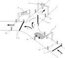
レーンA→Dには、基本的には、路側アンテナ3,5が備えられ、車載器との間で無線通信を行なっている。図4はレーンA→D,A→Eの詳細を示し、これに沿って更に説明する。車両が、一般道路8から進入して、予め開いている遮断機1を通り、車両検知装置2aにより検知され、無線通信が可能か否かを判定する路側アンテナ(ゲート前アンテナ)3の側を通過し、車両検知装置2bにより検知される。
The lanes A to D are basically provided with
ゲート前アンテナ3との間で無線通信が可能と判定されたとき、誘導装置4−2は閉じたままで誘導装置4−1が開き、車両検知装置2cの側を通り、路側アンテナ(ETCゲート)5から車載器に対する入口情報を受信して、車両は有料道路7へと進むことが出来る。 When it is determined that wireless communication with the antenna in front of the gate 3 is possible, the guidance device 4-1 opens while the guidance device 4-2 is closed, passes by the vehicle detection device 2c, and is a roadside antenna (ETC gate). Upon receiving the entrance information for the on-board unit from 5, the vehicle can proceed to the toll road 7.
ゲート前アンテナ3との間で無線通信が不能又は不可と判定されたとき、誘導装置4−1は閉じたままで誘導装置4−2が開き、レーンEに進んで、車両検知装置2dの側を通り、再度レーンA,B,Cのいずれかを選択する地点に戻る。従来、再進入レーンEが存在しなかったので、開閉バー4−1が下りて進行出来なくなると、車両を止めてインターホン等で係員を呼び出す必要があった。これにより、料金所9の渋滞が助長され、ETCの本来の目的が達成できない状態となる。また、開閉バー4−1が下りて通行を止められた車両が、レーンDからバック走行をしてレーンAから出ようとすると、後続の車両と衝突するおそれもあり、非常に危険であった。しかし、再進入レーンEを設けることで、このような不具合、危険をシステム的に解決することができる。
When it is determined that wireless communication with the antenna in front of the gate is impossible or impossible, the guidance device 4-2 opens while the guidance device 4-1 is closed, proceeds to lane E, and moves to the side of the
ここで、図7のように(これは出口料金所の例であるが)、無線通信が不能・不可の車両がレーンAから、レーンEを通って、レーンB又はCの通行券発券ボックス6より前の地点に合流するような構成にしてもよい。なお、レーンB,Cは一般車用レーンであり、通行券発券ボックス6が夫々設けられている。 Here, as shown in FIG. 7 (this is an example of an exit tollhouse), a vehicle whose wireless communication is impossible or impossible passes from lane A through lane E, and a toll ticketing box 6 for lane B or C. It may be configured to join the earlier point. The lanes B and C are lanes for general vehicles, and a toll ticket issuing box 6 is provided respectively.
図4に戻り、ゲート前アンテナ3には、車両に搭載されたETC車載器とデータを通信する通信手段および受信したデータを認識して、ETCによる料金徴収が可能か判定する判定手段とが備えられている。 Returning to FIG. 4, the antenna 3 in front of the gate is provided with a communication means for communicating data with the ETC on-board unit mounted on the vehicle and a determination means for recognizing the received data and determining whether or not the charge can be collected by ETC. Has been done.
誘導装置4−1,4−2としては、例えば遮断機の形態にし、ルートDへ誘導する時にはルートD側の遮断機を開けてルートE側の遮断機を閉じ、ルートEへ誘導する時にはルートE側の遮断機を開けてルートD側の遮断機を閉じて誘導する方法がある。また、表示パネルの形態にし、それぞれのルートで「通行可能」「通行不可」などの文字を表示させてもよいし、通行可能なルートには「↑」(矢印)、通行不可能なルートには「×」(バツ印)などの記号や絵を表示させてもよい。また、「ETC読み取り不能」等のルートEへ誘導する理由を表示させてもよい。また、遮断機形式と表示パネル形式とを併用してもよい。 The guidance devices 4-1 and 4-2 are, for example, in the form of a breaker, and when guiding to route D, the breaker on the route D side is opened, the breaker on the route E side is closed, and when guiding to route E, the route is taken. There is a method of opening the barrier on the E side and closing the barrier on the route D side for guidance. In addition, the display panel may be used to display characters such as "passable" and "impossible" for each route, and "↑" (arrow) for passable routes and impassable routes. May display a symbol or picture such as "x" (cross mark). Further, the reason for guiding to the route E such as "ETC unreadable" may be displayed. Further, the barrier type and the display panel type may be used together.
通行券発券ボックス10は、現金や磁気カードなどで料金徴収を行なうための有人又は無人の設備のことであって、現在高速道路の料金所などで導入されているものである。 The toll ticket issuing box 10 is a manned or unmanned facility for collecting tolls with cash, a magnetic card, or the like, and is currently introduced at tollhouses on expressways.
図4に示す複数個の車両検知装置2a,2b,2c,2dの機能について着目しながら、図5に示すフローを使って、図3,4の車両誘導システムの誘導方法を簡単に説明する。最初の車両検知装置2aが車両の進入を検知すると(ステップS02)、遮断機1を閉じて後続車との間を一定の間隔を空けるようにしている(ステップS03)。遮断機1は、後述するように、車両検知装置2c又は2dが車両を検知しないと開かないので、先行車と後続車の衝突が回避でき、また先行車がレーンAを逆走するのを阻止できる。2番目の車両検知装置2bが進入車両を検知すると(ステップS05)、車両がゲート前アンテナ3を通過したことを確認し、このタイミングで通信可能又は通信不能・不可のいずれであるかを判定する(ステップS06,S07)。判定時期を確定し、車両が通過していない状態と車両の通過したにも拘わらず無線通信が行なわれなかった状態とを識別できるようにしている。
While paying attention to the functions of the plurality of
通信可能であれば、誘導装置4−1が開きレーンDに誘導され有料道路7に進む(ステップS08)。反対に、通信不能・不可であれば、誘導装置4−2が開きレーンEに誘導され、再度レーンA,B,Cを選択する場所に戻る(ステップS13)。ここで、「通信不能・不可」には、一般車が誤って進入した場合、及びETC車が何らかの理由で無線通信に成功しなかった場合を含んでいる。 If communication is possible, the guidance device 4-1 opens and is guided to the lane D to proceed to the toll road 7 (step S08). On the contrary, if communication is impossible or impossible, the guidance device 4-2 opens and is guided to the lane E, and returns to the place where the lanes A, B, and C are selected again (step S13). Here, "communication impossible / impossible" includes the case where a general vehicle accidentally enters and the case where the ETC vehicle does not succeed in wireless communication for some reason.
3番目の車両検知装置2cが進入車両を検知すると(ステップS09)、この車両はレーンA→Dから脱出しつつあるので遮断機1を開き(ステップS10)、同様に、4番目の車両検知装置2dが進入車両を検知すると(ステップS14)、レーンA→Eから脱出しつつあるので遮断機1を開くようにしている(ステップS15)。これにより、1台の車両が、遮断機1から車両検知装置2c,2dの区間に進入しているときはこの区間は一種の閉鎖領域となり、1台の車両のみの存在が許されるようになっている。このため、この閉鎖領域では先行車と後続車の衝突は起こらない。なお、ETCシステムが正常に働いている限り、遮断機1が閉じている時間は、車両が遮断機1からETCゲート5を通過するまでの時間であり、ほんの数秒であり、ETCシステム本来のノンストップ走行は実質的に確保されている。
When the third vehicle detection device 2c detects an approaching vehicle (step S09), since this vehicle is escaping from lanes A → D, the barrier 1 is opened (step S10), and similarly, the fourth vehicle detection device When 2d detects an approaching vehicle (step S14), it is escaping from lanes A → E, so the barrier 1 is opened (step S15). As a result, when one vehicle enters the section of the
なお、路側アンテナであるゲート前アンテナ3とETCゲート5を一緒にして、ゲート前アンテナ3の地点に設置し、無線通信が可能であるか否かの判定と可能な場合に入口情報の送信とを一度に実行してもよい。
The front-gate antenna 3 and the
また、上述の実施例は入口発券方式であるが、本発明は、これに限定されるものではなく、単純徴収方式においても採用できる。この場合は、有料道路の入口と出口の間で少なくとも1カ所にこのような誘導システムを設ければよい。 Further, although the above-mentioned embodiment is an entrance ticketing method, the present invention is not limited to this, and can be adopted in a simple collection method. In this case, such a guidance system may be provided at least one place between the entrance and the exit of the toll road.
図3,4の誘導システムは、各遮断機,各車両検知装置,ゲート前アンテナ,ETCゲート等と接続されたコンピュータ(図示せず。)によって実行される。上述した誘導方法は、プログラム化されてこのコンピュータに読み込まれ、実行される。更に、このプログラムは、適当な記録媒体に記録されている。本発明は、上述の誘導システムのみならず、このような誘導方法、この誘導方法を実行するプログラム、このプログラムを記録した記録媒体をも含んでいる。 The guidance system of FIGS. 3 and 4 is executed by a computer (not shown) connected to each barrier, each vehicle detection device, an antenna in front of the gate, an ETC gate, and the like. The guidance method described above is programmed, loaded into this computer, and executed. Furthermore, this program is recorded on a suitable recording medium. The present invention includes not only the above-mentioned guidance system, but also such a guidance method, a program for executing the guidance method, and a recording medium on which the program is recorded.
この実施形態によれば、次のような効果が得られる。
(1)本実施例は、従来のインターチェンジに大幅な変更を加えることなく、新たに再進入レーンEを用意するだけで実現できる。
(2)ETCレーンに進入した後、ETC無線通信が不能・不可であっても再進入レーンEが用意されているので渋滞が発生しない。
(3)車両検知装置2aが進入車両を検知すると遮断機1を閉じ、その後車両検知装置2c,2dが進入車両を検知しないと遮断機1を開けないので、進入車両の不法な逆方向走行を阻止することができる。
(4)更に、遮断機1と車両検知装置2c,2dの間にある車両は1台限定されるので、進入車両と後続車両との間で衝突事故が回避できる。
According to this embodiment, the following effects can be obtained.
(1) This embodiment can be realized only by preparing a new re-entry lane E without making major changes to the conventional interchange.
(2) After entering the ETC lane, even if ETC wireless communication is impossible or impossible, the re-entry lane E is prepared, so congestion does not occur.
(3) When the vehicle detection device 2a detects an approaching vehicle, the barrier 1 is closed, and then the barrier 1 cannot be opened unless the
(4) Further, since the number of vehicles between the barrier 1 and the
[出口料金所用のETCシステム利用車両誘導システム]
図6は出口料金所におけるETCシステムを利用した車両誘導システムを示す。
[Vehicle guidance system using ETC system for exit toll office]
FIG. 6 shows a vehicle guidance system using an ETC system at an exit tollhouse.
車両は、有料道路7から一般道路8向かって進行し、その間に料金所9が設けられている。従来、料金所には、3つのレーンが用意されていた。レーン(A→D)はETC専用、レーンB,Cは一般車用である。本実施形態では、新たに再進入レーンEが用意されている。 The vehicle travels from the toll road 7 toward the general road 8, and a tollhouse 9 is provided between them. Conventionally, three lanes have been prepared at the tollhouse. Lanes (A → D) are for ETC only, and lanes B and C are for general vehicles. In this embodiment, a new re-entry lane E is prepared.
図6の出口料金所用のETCシステム利用車両誘導システムは、基本的に、図3,4のそれと同じである。 The vehicle guidance system using the ETC system for the exit toll station in FIG. 6 is basically the same as that in FIGS. 3 and 4.
図6に示す複数個の車両検知装置2a,2b,2c,2dの機能について着目しながら、図8に示すフローを使って図6,7の車両誘導システムの誘導方法を簡単に説明する。最初の車両検知装置2aが車両の進入を検知すると(ステップS22)、遮断機1を閉じて後続車との間を一定の間隔を空けるようにしている(ステップS23)。2番目の車両検知装置2bが進入車両を検知すると(ステップS25)、車両がゲート前アンテナ3を通過したことを確認し、このタイミングで通信可能又は通信不能・不可のいずれであるかを判定する(ステップS26,S27)。通信可能であれば、誘導装置4−1が開きレーンDに誘導され一般道路8に進む。反対に、通信不能・不可であれば、誘導装置4−2が開き再進入レーンEに誘導され、再度レーンA,B,Cを選択する場所に戻る。なお、図7に示すように、一般車レーンB又はCに誘導するようにしてもよい。
While paying attention to the functions of the plurality of
この時、3番目の車両検知装置2cが進入車両を検知すると(ステップS29)、この車両はレーンA→Dから脱出しつつあるので遮断機1を開き(ステップS30)、同様に、4番目の車両検知装置2dが進入車両を検知すると(ステップS34)、レーンA→Eから脱出しつつあるので遮断機1を開くようになっている(ステップS35)。
At this time, when the third vehicle detection device 2c detects an approaching vehicle (step S29), since this vehicle is escaping from lanes A → D, the barrier 1 is opened (step S30), and similarly, the fourth vehicle is detected. When the
同様に、図6,7の誘導システムは、各遮断機,各車両検知装置,ゲート前アンテナ,ETCゲート等と接続されたコンピュータ(図示せず。)によって実行される。上述した誘導方法は、プログラム化されてこのコンピュータに読み込まれ、実行される。更に、このプログラムは、適当な記録媒体に記録されている。本発明は、上述の誘導システムのみならず、このような誘導方法、この誘導方法を実行するプログラム、このプログラムを記録した記録媒体をも含んでいる。 Similarly, the guidance system of FIGS. 6 and 7 is executed by a computer (not shown) connected to each barrier, each vehicle detection device, an antenna in front of the gate, an ETC gate, and the like. The guidance method described above is programmed, loaded into this computer, and executed. Furthermore, this program is recorded on a suitable recording medium. The present invention includes not only the above-mentioned guidance system, but also such a guidance method, a program for executing the guidance method, and a recording medium on which the program is recorded.
この実施形態によれば、上述した(1)〜(4)と同じ効果が得られる。 According to this embodiment, the same effects as those described in (1) to (4) described above can be obtained.
[その他の応用例]
(逆進入防止機能を充実させたインターチェンジ)
しかしながら図4で説明した実施例では、料金不払いなどを目的とした不正車両が、ETC車用レーンの出口や離脱レーンの出口から遡ってETC車用レーンに逆進入することを防ぐことが出来ないという問題点を有している。これを解決するため、次に説明する実施形態では、レーンD及びレーンEの各々に対して、同様に遮断機と車両検知装置の組み合わせによる逆走防止手段を設けている。
[Other application examples]
(Interchange with enhanced reverse entry prevention function)
However, in the embodiment described with reference to FIG. 4, it is not possible to prevent an illegal vehicle for the purpose of non-payment of charges from entering the ETC vehicle lane retroactively from the exit of the ETC vehicle lane or the exit of the departure lane. It has the problem of. In order to solve this problem, in the embodiment described below, a reverse run prevention means is similarly provided for each of the lanes D and E by a combination of a breaker and a vehicle detection device.
図9は、図4の変形例であり、逆進入防止機能を充実させたインターチェンジの構成を示す図である。図10は、図9の車両誘導システムの誘導方法を説明するフローチャートである。 FIG. 9 is a modification of FIG. 4, and is a diagram showing a configuration of an interchange with an enhanced reverse entry prevention function. FIG. 10 is a flowchart illustrating a guidance method of the vehicle guidance system of FIG.
図9のインターチェンジの構成を、図4のそれと比較すると、図4で説明した閉鎖区間(遮断機1〜遮断機4−1,4−2の区間)に加えて、閉鎖区間F(遮断機1−2〜遮断機4−1の区間)と閉鎖区間G(遮断機1−3〜遮断機4−2の区間)とを形成している。図9に示すように、閉鎖区間Fを形成するため、新たに遮断機1−2,車両検知装置2e,閉鎖区間センサー16を設け、また、閉鎖区間Gを形成するため、新たに遮断機1−3,車両検知装置2f,閉鎖区間センサー17を設け、更に閉鎖区間センサー18を設けている。 Comparing the configuration of the interchange of FIG. 9 with that of FIG. 4, in addition to the closed section (section of the barrier 1 to the barrier 4-1 and 4-2) described in FIG. 4, the closed section F (breaker 1) -2 to the section of the barrier 4-1) and the closed section G (the section of the barrier 1-3 to the barrier 4-2) are formed. As shown in FIG. 9, in order to form the closed section F, a breaker 1-2, a vehicle detection device 2e, and a closed section sensor 16 are newly provided, and in order to form the closed section G, a new breaker 1 is provided. -3, a vehicle detection device 2f, a closed section sensor 17 is provided, and a closed section sensor 18 is further provided.
図10のフローを、図8のそれと比較すると、その相違は実質的には、図10にはステップS50〜54,56,59〜62が新たに追加されている点にある。 Comparing the flow of FIG. 10 with that of FIG. 8, the difference is substantially that steps S50 to 54, 56, 59 to 62 are newly added to FIG. 10.
図9,10を参照しながら、この実施形態を簡単に説明すると、レーンDに車両が入る時は、車両検知装置2cが車両を検知すると(ステップS49)、遮断機4−1を閉じて遮断機1−2を開き(ステップS50)、その後ゲート前アンテナ3が後続車両を認識判断するまで(ステップS48)遮断機4−1を閉じたままにしておく。車両検知装置2eが車両を検知すると(ステップS52)遮断機1−2を閉じ(ステップS53)、レーンDの出口から不正車両が逆進入することを防ぐ。車両区間センサー16が閉鎖区間Fに車両がいないことを確認すると(ステップS54)、遮断機1を開いて(ステップS55)後続車両の進入が可能となる。万一、別の不正車両が閉鎖区間Fを出る車両とすれ違いに逆進入した場合でも、閉鎖区間センサー16が閉鎖区間Fに車両がいると判定すると(ステップS54)、監視センターへ通報する等の処理を行なって、不正車両をそれ以上進入させない。 To briefly explain this embodiment with reference to FIGS. 9 and 10, when a vehicle enters the lane D, when the vehicle detection device 2c detects the vehicle (step S49), the barrier 4-1 is closed to cut off. The machine 1-2 is opened (step S50), and then the barrier 4-1 is kept closed until the antenna 3 in front of the gate recognizes and determines the following vehicle (step S48). When the vehicle detection device 2e detects a vehicle (step S52), the barrier 1-2 is closed (step S53) to prevent an unauthorized vehicle from entering backward from the exit of the lane D. When the vehicle section sensor 16 confirms that there is no vehicle in the closed section F (step S54), the barrier 1 is opened (step S55) and the following vehicle can enter. Even if another illegal vehicle enters the closed section F by passing the vehicle, if the closed section sensor 16 determines that the vehicle is in the closed section F (step S54), the monitoring center is notified. Process and prevent unauthorized vehicles from entering any further.
レーンEに関しても同様である。レーンEに車両が入る時は、車両検知装置2dが車両を検知すると(ステップS58)、遮断機4−2を閉じて遮断機1−3を開き(ステップS59)、その後ゲート前アンテナ3が後続車両を認識判断するまで(ステップS57)遮断機4−2を閉じたままにしておく。車両検知装置2fが車両を検知すると(ステップS60)遮断機1−3を閉じ(ステップS61)、レーンEの出口から不正車両が逆進入することを防ぐ。車両区間センサー17が閉鎖区間Gに車両がいないことを確認すると(ステップS62)、遮断機1を開いて(ステップS63)後続車両の進入が可能となる。万一、別の不正車両が閉鎖区間Fを出る車両とすれ違いに逆進入した場合でも、閉鎖区間センサー17が閉鎖区間Gに車両がいると判定すると(ステップS62)、監視センターへ通報する等の処理を行なって、不正車両をそれ以上進入させない。
The same applies to lane E. When a vehicle enters lane E, when the
更に、必要に応じて、閉鎖区間センサー18を設けて、レーンAの車両の有無を最終確認してもよい。 Further, if necessary, a closed section sensor 18 may be provided to finally confirm the presence or absence of a vehicle in lane A.
閉鎖区間センサーで撮影された映像は、監視センター(図示せず。)のモニタに表示させ、監視員がこれを監視している。ここで、閉鎖区間センサーは、必要に応じて、通常の可視カメラでもよく、或いは赤外線カメラでもよく、或いは両者を併用することもできる。赤外線カメラを用いると、車両のエンジン部の高温を検出するので、複数台の車両が同時に進入してきても、これらを識別することができる。 The image taken by the closed section sensor is displayed on the monitor of the monitoring center (not shown), and the observer monitors it. Here, the closed section sensor may be a normal visible camera, an infrared camera, or a combination of both, if necessary. When an infrared camera is used, the high temperature of the engine portion of the vehicle is detected, so that even if a plurality of vehicles enter at the same time, they can be identified.
この実施形態は、入口エンターチェンジ及び出口インターチェンジのいずれにも適用できることを承知されたい。 Please be aware that this embodiment can be applied to both entrance and exit interchanges.
(スマートインターチェンジの車両誘導システム)
図11は、変形例を示し、具体的には、スマートインターチェンジに本発明の車両誘導システムを導入した例である。スマートインターチェンジとは、高速道路のパーキング-エリアやサービス-エリアにETCゲートを設置して一般道と接続する、ETC車専用のインターチェンジ(料金所)のことで、2004年から実験的に導入が計画されている。従来のインターチェンジに比べ低費用で建設・管理できるのが特徴で、高速道路の利便性の向上や、周辺地域の活性化が期待されている。しかしながら、一般車がスマートインターチェンジに進入して立ち往生した場合に備えて係員が常駐していなければならないので、経済的でない。
(Vehicle guidance system for smart interchanges)
FIG. 11 shows a modified example, specifically, an example in which the vehicle guidance system of the present invention is introduced into a smart interchange. A smart interchange is an interchange (tollhouse) exclusively for ETC vehicles that installs ETC gates in the parking-area and service-area of expressways to connect to general roads, and is planned to be introduced experimentally from 2004. Has been done. It is characterized by being able to be constructed and managed at a lower cost than conventional interchanges, and is expected to improve the convenience of expressways and revitalize the surrounding area. However, it is not economical because a staff member must be stationed in case a general vehicle enters the smart interchange and gets stuck.
図11に示すように、一般道路8と有料道路7との間に、パーキング-エリア又はサービス-エリア11が設けられている。一般道路8から有料道路7に入るための入口料金所12と、反対に有料道路7から一般道路8に出るための出口料金所13がある。一般車レーンB,Cが無いことを除き、入口料金所12のレーン(A→D)と(A→E)の役割、及び出口料金所13のレーン(A→D)と(A→E)の役割は、図3,4,6及び7のそれと同じである。
As shown in FIG. 11, a parking-area or a service-area 11 is provided between the general road 8 and the toll road 7. There is an
本発明の車両誘導システムによれば、一般車の進入を阻止し、ETC車のみを対象に出来るので、インターチェンジを無人化でき、経済効果が期待できる。 According to the vehicle guidance system of the present invention, it is possible to prevent the entry of general vehicles and target only ETC vehicles, so that the interchange can be unmanned and economic effects can be expected.
(有料駐車場等の車両誘導システム)
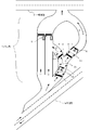
また、本発明は有料道路と一般道路を結ぶ料金所に限定されるものではなく、有料駐車場、または有料洗車場、またはドライブインシアターなどの、利用するために料金が必要なエリアに設置することもできる。図12は本発明の車両誘導システムを導入した有料駐車場の一実施例である。
(Vehicle guidance system for pay parking lots, etc.)
Further, the present invention is not limited to a tollhouse connecting a toll road and a general road, and is installed in an area where a toll is required, such as a toll parking lot, a toll car wash, or a drive-in theater. You can also do it. FIG. 12 is an example of a pay parking lot in which the vehicle guidance system of the present invention is introduced.
入口より、車両(ETC車及び一般車)14が遮断機1を通って駐車場に入る。ゲート前アンテナ3によりETC通信可能か否かが判定され、可能であればルートDの方向へ誘導される。駐車後、ETC車専用出口から外に出る。無線通信不能・不可であれば、ルートEの方向へ誘導され、入場券発券所15で入場時刻が記載された入場券を受領する。駐車後、料金徴収所6で料金を支払い、一般車両用出口から外に出る。 From the entrance, the vehicle (ETC vehicle and general vehicle) 14 enters the parking lot through the barrier 1. Whether or not ETC communication is possible is determined by the antenna 3 in front of the gate, and if possible, the antenna 3 is guided in the direction of route D. After parking, go out from the ETC car exclusive exit. If wireless communication is not possible or not, you will be guided in the direction of Route E, and you will receive an admission ticket with the admission time at the admission ticket issuing office 15. After parking, pay the fee at the toll collection point 6 and go out from the general vehicle exit.
この場合、ETC車に対しては人手の関与を省略出来るので、人件費の節約が可能となる。 In this case, since the involvement of manpower can be omitted for the ETC vehicle, labor costs can be saved.
同様に、図9,11,12のシステムは、各遮断機,各車両検知装置,ゲート前アンテナ,ETCゲート等と接続されたコンピュータ(図示せず。)によって実行される。上述した誘導方法は、プログラム化されてこのコンピュータに読み込まれ、実行される。更に、このプログラムは、適当な記録媒体に記録されている。本発明は、上述の誘導システムのみならず、このような誘導方法、この誘導方法を実行するプログラム、このプログラムを記録した記録媒体をも含んでいる。 Similarly, the system of FIGS. 9, 11 and 12 is executed by a computer (not shown) connected to each barrier, each vehicle detection device, an antenna in front of the gate, an ETC gate, and the like. The guidance method described above is programmed, loaded into this computer, and executed. Furthermore, this program is recorded on a suitable recording medium. The present invention includes not only the above-mentioned guidance system, but also such a guidance method, a program for executing the guidance method, and a recording medium on which the program is recorded.
以上、本発明に係る車両誘導システムに係る実施形態について記載したが、以上の記載は、例示であって、この記載により本発明は何ら限定されるものではないことを承知されたい。当業者がなし得る変更・改良は本発明の技術的範囲内のものである。本発明の技術的範囲は、添付の特許請求の範囲の記載に基づいて定められる。
[発明1]
一般道路と有料道路との間の料金所にETC車用レーンを有するインターチェンジに利用される車両誘導システムに於いて、
路側アンテナと車載器と間で通信不能又は通信不可が発生したとき、車両が前記ETC車用レーンから離脱しえる手段を設けたことを特徴とする、システム。
[発明2]
発明1に記載の車両誘導システムに於いて、
前記ETC車用レーンから離脱しえる手段は、前記ETC車用レーンから分岐して前記車両が前記料金所へ再進入するレーン又は一般者用レーンへ誘導されるレーンからなる、システム。
[発明3]
発明1に記載の車両誘導システムにおいて、
前記路側アンテナは、車載器との間で無線通信可能か否かを判定するためのゲート前アンテナと入口情報及び料金情報の送受信を行なうETCアンテナとを有している、システム。
[発明4]
発明1に記載の車両誘導システムにおいて、
前記システムは、遮断機、第1の車両検知装置、ゲート前アンテナ、第2の車両検知装置、誘導手段、第3の車両検知装置、第4の車両検知装置及びETCゲートを有し、
前記第1の車両検知装置が車両の進入を検知すると、前記遮断機を閉じて後続車との間を一定の間隔を空けるようにし、
前記第2の車両検知装置が進入車両を検知すると、車両がゲート前アンテナを通過したことを確認して、このタイミングで通信可能又は通信不能・不可のいずれであるかを判定し、
前記第3又は第4の車両検知装置が進入車両を検知すると、後続車のために前記遮断機を開く、システム。
[発明5]
発明1に記載の車両誘導システムにおいて、
前記システムは、少なくとも1つの誘導装置を有し、
前記ゲート前アンテナが車載器との間で通信可能又は通信不可・不能と判定したとき、その判定結果に基づいて前記誘導装置により車両を所定の誘導先に誘導する、システム。
[発明6]
ETC車載器搭載車が一般道路と有料道路との出入りをする時に、ETC車専用出入口から出入りをする車両を誘導するシステムであって、
一般道路と有料道路との出入りをする車両を検知する検知手段と、
車両に搭載されたETC車載器とデータを通信する通信手段と、
前記通信手段によって受信したデータを認識して、ETCによる料金徴収が可能か判定する判定手段と、
前記判定手段により判定した結果に従って、ETCによる料金徴収が可能な車両を、ETCゲートを通って一般道路から有料道路へ入る、または有料道路から一般道路へ出るルートへ誘導し、ETCによる料金徴収が不可能な車両を、再度出入口手前へ戻るルート又は一般車用出入口へ誘導する誘導手段を備え、
前記検知手段により車両の進入が検知された場合、遮断機を下ろすことにより、進入した車両のバック走行と後続の車両の進入を防ぐことを特徴とする、システム。
[発明7]
有料道路料金所、サービスエリア又はパーキングエリアに設置されている、発明6に記載のシステム。
[発明8]
少なくとも有料駐車場、有料洗車場及びドライブインシアターを含む有料エリアに設置されている、発明6に記載のシステム。
[発明9]
一般道路と有料道路との間の料金所にETC車用レーンを有するインターチェンジに利用される車両誘導システムに於いて、
前記ETC車用レーンの途中から分岐する、路側アンテナと車載器との間で通信不能又は通信不可が発生したときに車両を前記ETC車用レーンから離脱させるためのレーンを設け、
前記ETC車用レーンから離脱させるためのレーンは、前記車両を前記料金所へ再進入させるレーン又は一般車用レーンへ誘導するレーンであり、
前記分岐する地点から先の前記ETC車用レーンの部分及び前記離脱レーンの部分に対して、別の不正車両の逆進入を防止する閉鎖区間を夫々設けている、車両誘導システム。
[発明10]
発明9に記載の車両誘導システムにおいて、
前記路側アンテナは、車載器との間で無線通信可能か否かを判定するためのゲート前アンテナと入口情報及び料金情報の送受信を行なうETCアンテナとを有している、システム。
[発明11]
発明9に記載の車両誘導システムにおいて、
前記システムは、第1の遮断機、第1の車両検知装置、ゲート前アンテナ、第2の車両検知装置、閉鎖区間を作るための遮断機を含む誘導手段を有しており、
前記分岐する地点から先の、前記ETC車用レーンに第1の閉鎖区間センサーを有し、前記分岐する地点から先の、前記ETC車用レーンの第1の閉鎖区間に、第3の車両検知装置、ETCゲート、第2の遮断機及を有し、前記第1の閉鎖区間の先に第4の車両検知装置を有し、
また前記分岐する地点から先の、前記離脱レーンに第2の閉鎖区間センサーを有し、前記離脱レーンの第2の閉鎖区間に、第5の車両検知装置、第3の遮断機を有し、前記第2の閉鎖区間の先に第6の車両検知装置を有し、
前記第1の車両検知装置が車両の進入を検知すると、前記第1の遮断機を閉じて後続車との間を区切るようにし、
前記第2の車両検知装置が進入車両を検知すると、車両がゲート前アンテナを通過したことを確認して、このタイミングで通信可能又は通信不能・不可のいずれであるかを判定し、
前記閉鎖区間において車両検知装置が進入車両を検知すると、誘導手段の遮断機を閉じ、前記閉鎖区間の先に備えられた車両検知装置が車両の通過を検知すると閉鎖区間出口の遮断機を閉じることによって、別の不正車両が閉鎖区間の出口側から逆進入することを防止し、
万一、別の不正車両が閉鎖区間を出る車両とすれ違いに逆進入した場合でも、閉鎖区間センサーが閉鎖区間に車両がいると判定すると、監視センターへ通報する等の処理を行ない、
閉鎖区間センサーが閉鎖区間に車両がいないと判定すると、後続車のために第1の遮断機を開く、システム。
[発明12]
一般道路と有料道路との間の料金所にETC車用レーンを有するインターチェンジに利用される車両誘導方法であって、
前記インターチェンジには、路側アンテナと車載器と間で通信不能又は通信不可が発生したとき車両を前記ETC車用レーンから離脱させるためのレーンが設けられ、
前記ETC車用レーンから離脱させるためのレーンは、前記車両を前記料金所へ再進入させるレーン又は一般車用レーンへ誘導するレーンであり、
前記車両誘導方法は、
前記第1の車両検知装置が車両の進入を検知すると、第1の遮断機を閉じて後続車との間を一定の間隔を空けるようにし、
前記第2の車両検知装置が進入車両を検知すると、車両がゲート前アンテナを通過したことを確認して、このタイミングで通信可能又は通信不能・不可のいずれであるかを判定し、
通信可能と判断された時、第2のゲートを開けてETCゲート及び第3の車両検知装置に導き、所望の道路に送り出し、
通信不能・不可と判断された時、第3のゲートを開けて第4の車両検知装置に導き、前記再進入レーンに送り出し、
前記第3又は第4の車両検知装置が進入車両を検知すると、後続車のために前記第1の遮断機を開く、各ステップを含む車両誘導方法。
[発明13]
一般道路と有料道路との間の料金所にETC車用レーンを有するインターチェンジに利用される車両誘導方法であって、
前記インターチェンジには、第1の遮断機、第1の車両検知装置、ゲート前アンテナ、第2の車両検知装置、閉鎖区間を作るための遮断機を含む誘導手段を有しており、
前記分岐する地点から先の、前記ETC車用レーンに第1の閉鎖区間センサーを有し、前記分岐する地点から先の、前記ETC車用レーンの第1の閉鎖区間に、第3の車両検知装置、ETCゲート、第2の遮断機及を有し、前記第1の閉鎖区間の先に第4の車両検知装置を有し、
また前記分岐する地点から先の、前記離脱レーンに第2の閉鎖区間センサーを有し、前記離脱レーンの第2の閉鎖区間に、第5の車両検知装置、第3の遮断機を有し、前記第2の閉鎖区間の先に第6の車両検知装置を有し、
前記車両誘導方法は、
前記第1の車両検知装置が車両の進入を検知すると、前記第1の遮断機を閉じて後続車との間を区切るようにし、
前記第2の車両検知装置が進入車両を検知すると、車両がゲート前アンテナを通過したことを確認して、このタイミングで通信可能又は通信不能・不可のいずれであるかを判定し、
前記閉鎖区間において車両検知装置が進入車両を検知すると、誘導手段の遮断機を閉じ、前記閉鎖区間の先に備えられた車両検知装置が車両の通過を検知すると閉鎖区間出口の遮断機を閉じることによって、別の不正車両が閉鎖区間の出口側から逆進入することを防止し、
万一、別の不正車両が閉鎖区間を出る車両とすれ違いに逆進入した場合でも、閉鎖区間センサーが閉鎖区間に車両がいると判定すると、監視センターへ通報する等の処理を行ない、
閉鎖区間センサーが閉鎖区間に車両がいないと判定すると、後続車のために第1の遮断機を開く、各ステップを含む車両誘導方法。
[発明14]
コンピュータに発明12又は13記載の車両誘導方法の各ステップを実行させるコンピュータプログラム。
[発明15]
発明14記載のコンピュータプログラムを記録した記録媒体。
The embodiment of the vehicle guidance system according to the present invention has been described above, but it should be noted that the above description is an example and the present invention is not limited to this description. Changes and improvements that can be made by those skilled in the art are within the technical scope of the present invention. The technical scope of the present invention is defined based on the description of the appended claims.
[Invention 1]
In a vehicle guidance system used for interchanges that have ETC vehicle lanes at tollhouses between general roads and toll roads.
A system characterized in that a means for allowing a vehicle to leave the ETC vehicle lane when communication failure or communication failure occurs between a roadside antenna and an on-board unit is provided.
[Invention 2]
In the vehicle guidance system according to the first invention.
The means for leaving the ETC vehicle lane is a system consisting of a lane that branches off from the ETC vehicle lane and is guided to a lane for the vehicle to re-enter the tollhouse or a lane for the general public.
[Invention 3]
In the vehicle guidance system according to the invention 1.
The roadside antenna is a system having a front-gate antenna for determining whether or not wireless communication is possible with an on-board unit and an ETC antenna for transmitting and receiving entrance information and charge information.
[Invention 4]
In the vehicle guidance system according to the invention 1.
The system includes a barrier, a first vehicle detection device, a gate front antenna, a second vehicle detection device, a guiding means, a third vehicle detection device, a fourth vehicle detection device, and an ETC gate.
When the first vehicle detection device detects the approach of a vehicle, the barrier is closed so that there is a certain distance from the following vehicle.
When the second vehicle detection device detects an approaching vehicle, it is confirmed that the vehicle has passed the antenna in front of the gate, and at this timing, it is determined whether communication is possible or communication is impossible or impossible.
A system that opens the barrier for the following vehicle when the third or fourth vehicle detection device detects an approaching vehicle.
[Invention 5]
In the vehicle guidance system according to the invention 1.
The system has at least one guidance device.
A system that guides a vehicle to a predetermined guidance destination by the guidance device based on the determination result when the antenna in front of the gate determines that communication is possible or communication is impossible / impossible with the vehicle-mounted device.
[Invention 6]
It is a system that guides vehicles entering and exiting from the ETC vehicle dedicated entrance when a vehicle equipped with an ETC on-board unit enters and exits a general road and a toll road.
Detection means for detecting vehicles entering and exiting general roads and toll roads,
A communication means for communicating data with the ETC on-board unit mounted on the vehicle,
A determination means that recognizes the data received by the communication means and determines whether or not the charge can be collected by ETC.
According to the result determined by the determination means, a vehicle that can collect tolls by ETC is guided to a route that enters a toll road from a general road through an ETC gate or goes out from a toll road to a general road, and the toll collection by ETC is performed. Equipped with a guidance means to guide the impossible vehicle to the route returning to the front of the doorway or the doorway for general vehicles.
A system characterized in that when the approach of a vehicle is detected by the detection means, the barrier is lowered to prevent the approaching vehicle from traveling backward and the following vehicle from entering.
[Invention 7]
The system according to invention 6, which is installed in a toll road tollhouse, a service area, or a parking area.
[Invention 8]
The system according to invention 6, which is installed in a pay area including at least a pay parking lot, a pay car wash, and a drive-in theater.
[Invention 9]
In a vehicle guidance system used for interchanges that have ETC vehicle lanes at tollhouses between general roads and toll roads.
A lane for separating the vehicle from the ETC vehicle lane when communication failure or communication failure occurs between the roadside antenna and the on-board unit, which branches from the middle of the ETC vehicle lane, is provided.
The lane for leaving the ETC vehicle lane is a lane for re-entering the tollhouse or a lane for guiding the vehicle to a general vehicle lane.
A vehicle guidance system in which a closed section for preventing reverse entry of another illegal vehicle is provided for a portion of the ETC vehicle lane and a portion of the departure lane beyond the branching point.
[Invention 10]
In the vehicle guidance system according to the invention 9.
The roadside antenna is a system having a front-gate antenna for determining whether or not wireless communication is possible with an on-board unit and an ETC antenna for transmitting and receiving entrance information and charge information.
[Invention 11]
In the vehicle guidance system according to the invention 9.
The system has a guiding means including a first barrier, a first vehicle detector, an antenna in front of the gate, a second vehicle detector, and a barrier for making a closed section.
A first closed section sensor is provided in the ETC vehicle lane ahead of the branch point, and a third vehicle detection is performed in the first closed section of the ETC vehicle lane ahead of the branch point. It has a device, an ETC gate, a second barrier and a fourth vehicle detection device ahead of the first closed section.
Further, a second closed section sensor is provided in the departure lane ahead of the branch point, and a fifth vehicle detection device and a third barrier are provided in the second closed section of the departure lane. A sixth vehicle detection device is provided at the end of the second closed section.
When the first vehicle detection device detects the approach of a vehicle, the first barrier is closed to separate the vehicle from the following vehicle.
When the second vehicle detection device detects an approaching vehicle, it is confirmed that the vehicle has passed the antenna in front of the gate, and at this timing, it is determined whether communication is possible or communication is impossible or impossible.
When the vehicle detection device detects an approaching vehicle in the closed section, the barrier of the guiding means is closed, and when the vehicle detection device provided at the tip of the closed section detects the passage of the vehicle, the barrier at the exit of the closed section is closed. Prevents another fraudulent vehicle from entering backwards from the exit side of the closed section.
Even if another fraudulent vehicle enters the vehicle by passing the vehicle leaving the closed section, if the closed section sensor determines that there is a vehicle in the closed section, the monitoring center will be notified.
A system that opens a first barrier for the following vehicle when the closed section sensor determines that there is no vehicle in the closed section.
[Invention 12]
A vehicle guidance method used for interchanges that have ETC vehicle lanes at tollhouses between general roads and toll roads.
The interchange is provided with a lane for separating the vehicle from the ETC vehicle lane when communication failure or communication failure occurs between the roadside antenna and the on-board unit.
The lane for leaving the ETC vehicle lane is a lane for re-entering the tollhouse or a lane for guiding the vehicle to a general vehicle lane.
The vehicle guidance method is
When the first vehicle detection device detects the approach of a vehicle, the first barrier is closed so that there is a certain distance from the following vehicle.
When the second vehicle detection device detects an approaching vehicle, it is confirmed that the vehicle has passed the antenna in front of the gate, and at this timing, it is determined whether communication is possible or communication is impossible or impossible.
When it is determined that communication is possible, the second gate is opened, guided to the ETC gate and the third vehicle detection device, and sent to the desired road.
When it is determined that communication is impossible or impossible, the third gate is opened, the vehicle is guided to the fourth vehicle detection device, and the vehicle is sent to the re-entry lane.
A vehicle guidance method including each step of opening the first barrier for a following vehicle when the third or fourth vehicle detection device detects an approaching vehicle.
[Invention 13]
A vehicle guidance method used for interchanges that have ETC vehicle lanes at tollhouses between general roads and toll roads.
The interchange has a guiding means including a first barrier, a first vehicle detector, an antenna in front of the gate, a second vehicle detector, and a barrier for creating a closed section.
A first closed section sensor is provided in the ETC vehicle lane ahead of the branch point, and a third vehicle detection is performed in the first closed section of the ETC vehicle lane ahead of the branch point. It has a device, an ETC gate, a second barrier and a fourth vehicle detection device ahead of the first closed section.
Further, a second closed section sensor is provided in the departure lane ahead of the branch point, and a fifth vehicle detection device and a third barrier are provided in the second closed section of the departure lane. A sixth vehicle detection device is provided at the end of the second closed section.
The vehicle guidance method is
When the first vehicle detection device detects the approach of a vehicle, the first barrier is closed to separate the vehicle from the following vehicle.
When the second vehicle detection device detects an approaching vehicle, it is confirmed that the vehicle has passed the antenna in front of the gate, and at this timing, it is determined whether communication is possible or communication is impossible or impossible.
When the vehicle detection device detects an approaching vehicle in the closed section, the barrier of the guiding means is closed, and when the vehicle detection device provided at the tip of the closed section detects the passage of the vehicle, the barrier at the exit of the closed section is closed. Prevents another fraudulent vehicle from entering backwards from the exit side of the closed section.
Even if another fraudulent vehicle enters the vehicle by passing the vehicle leaving the closed section, if the closed section sensor determines that there is a vehicle in the closed section, the monitoring center will be notified.
A vehicle guidance method comprising each step of opening a first barrier for a following vehicle when the closed section sensor determines that there is no vehicle in the closed section.
[Invention 14]
A computer program that causes a computer to execute each step of the vehicle guiding method according to the
[Invention 15]
A recording medium on which the computer program according to the
1:遮断機、 2,2a,2b,2c,2d:車両検知装置、 3:ゲート前アンテナ、 4:誘導装置、 5:ETCゲート、 6:料金徴収ボックス、 7:有料道路、 8:一般道路、 9:料金所、 10:通行券発券ボックス、 11:パーキングエリア,サービスエリア、 12:ETC車専用入口料金所、 13:ETC車専用出口料金所、 14:車両、 15:駐車券発行機、 16,17,18:閉鎖区間センサー 1: Breaker, 2,2a, 2b, 2c, 2d: Vehicle detection device, 3: Gate front antenna, 4: Guidance device, 5: ETC gate, 6: Toll collection box, 7: Toll road, 8: General road , 9: Tollhouse, 10: Toll ticketing box, 11: Parking area, Service area, 12: ETC car exclusive entrance tollhouse, 13: ETC car exclusive exit tollhouse, 14: Vehicle, 15: Parking ticket issuing machine, 16, 17, 18: Closed section sensor
Claims (6)
前記有料道路料金所、サービスエリア又はパーキングエリアに出入りをする車両を検知する第1の検知手段と、
前記第1の検知手段に対応して設置された第1の遮断機と、
車両に搭載されたETC車載器とデータを通信する通信手段と、
前記通信手段によって受信したデータを認識して、ETCによる料金徴収が可能か判定する判定手段と、
前記判定手段により判定した結果に従って、ETCによる料金徴収が可能な車両を、ETCゲートを通って前記有料道路料金所、サービスエリア又はパーキングエリアに入る、または前記有料道路料金所、サービスエリア又はパーキングエリアから出るルートへ通じる第1のレーンへ誘導し、ETCによる料金徴収が不可能な車両を、再度前記ETC車専用出入口手前へ戻るルート又は一般車用出入口に通じる第2のレーンへ誘導する誘導手段と、を備え、
前記誘導手段は、前記第1のレーンに設けられた第2の遮断機と、前記第2のレーンに設けられた第3の遮断機と、を含み、
さらに、前記第2の遮断機を通過した車両を検知する第2の検知手段と、前記第3の遮断機を通過した車両を検知する第3の検知手段と、を備え、
前記第2のレーンの前記第1のレーンとの接続部分の形状は、前記第1の遮断機を通過して前記第2のレーンに入り込むときの車両がスムーズに走行できる方向に折れ曲がった曲線路であり、
前記第1の検知手段により車両の進入が検知された場合、前記車両が通過した後に、前記第1の遮断機を下ろし、前記第2の検知手段により車両の通過が検知された場合、前記車両が通過した後に、前記第2の遮断機を下ろすことを特徴とする車両誘導システム。 It is a system that guides vehicles entering and exiting from the ETC vehicle exclusive entrance / exit installed in the toll road tollhouse, service area or parking area.
The first detection means for detecting a vehicle entering and exiting the toll road tollhouse, service area or parking area, and
A first barrier installed corresponding to the first detection means, and
A communication means for communicating data with the ETC on-board unit mounted on the vehicle,
A determination means that recognizes the data received by the communication means and determines whether or not the charge can be collected by ETC.
According to the result determined by the determination means, a vehicle capable of collecting tolls by ETC is entered into the toll road tollhouse, service area or parking area through the ETC gate, or the toll road tollhouse, service area or parking area. Guidance means to guide vehicles that cannot be charged by ETC to the first lane leading to the route exiting from, and to the route returning to the front of the ETC vehicle exclusive entrance or the second lane leading to the general vehicle entrance. And, with
The guiding means includes a second barrier provided in the first lane and a third barrier provided in the second lane.
Further, a second detecting means for detecting a vehicle that has passed through the second barrier and a third detecting means for detecting a vehicle that has passed through the third barrier are provided.
The shape of the connection portion of the second lane with the first lane is a curved road that is bent in a direction in which the vehicle can smoothly travel when passing through the first barrier and entering the second lane. And
When the approach of the vehicle is detected by the first detection means, the first barrier is lowered after the vehicle has passed, and when the passage of the vehicle is detected by the second detection means, the vehicle is said. A vehicle guidance system characterized in that the second barrier is lowered after the vehicle has passed.
Priority Applications (1)
| Application Number | Priority Date | Filing Date | Title |
|---|---|---|---|
| JP2021003822A JP6979255B2 (en) | 2019-10-07 | 2021-01-13 | Vehicle guidance system |
Applications Claiming Priority (2)
| Application Number | Priority Date | Filing Date | Title |
|---|---|---|---|
| JP2019184396A JP2020098569A (en) | 2019-10-07 | 2019-10-07 | Vehicle guide system |
| JP2021003822A JP6979255B2 (en) | 2019-10-07 | 2021-01-13 | Vehicle guidance system |
Related Parent Applications (1)
| Application Number | Title | Priority Date | Filing Date |
|---|---|---|---|
| JP2019184396A Division JP2020098569A (en) | 2019-10-07 | 2019-10-07 | Vehicle guide system |
Publications (3)
| Publication Number | Publication Date |
|---|---|
| JP2021064405A JP2021064405A (en) | 2021-04-22 |
| JP2021064405A5 JP2021064405A5 (en) | 2021-11-18 |
| JP6979255B2 true JP6979255B2 (en) | 2021-12-08 |
Family
ID=75488063
Family Applications (1)
| Application Number | Title | Priority Date | Filing Date |
|---|---|---|---|
| JP2021003822A Active JP6979255B2 (en) | 2019-10-07 | 2021-01-13 | Vehicle guidance system |
Country Status (1)
| Country | Link |
|---|---|
| JP (1) | JP6979255B2 (en) |
Family Cites Families (7)
| Publication number | Priority date | Publication date | Assignee | Title |
|---|---|---|---|---|
| JPH02104469U (en) * | 1989-01-30 | 1990-08-20 | ||
| JPH07320106A (en) * | 1994-05-23 | 1995-12-08 | Kokusai Electric Co Ltd | Automatic payment system for toll road fare |
| JP3427496B2 (en) * | 1994-07-25 | 2003-07-14 | 三菱電機株式会社 | Parking elevator system |
| JP3220658B2 (en) * | 1997-04-18 | 2001-10-22 | 株式会社日本ティーエムアイ | Vehicle traffic management system |
| JP3481856B2 (en) * | 1998-05-18 | 2003-12-22 | 日本信号株式会社 | Traffic regulation method and traffic regulation device |
| JP2002024881A (en) * | 2000-07-10 | 2002-01-25 | Nippon Signal Co Ltd:The | Control system for automobile parking |
| JP2003216990A (en) * | 2002-01-22 | 2003-07-31 | Fujitsu Ten Ltd | Charge discount system for toll road |
-
2021
- 2021-01-13 JP JP2021003822A patent/JP6979255B2/en active Active
Also Published As
| Publication number | Publication date |
|---|---|
| JP2021064405A (en) | 2021-04-22 |
Similar Documents
| Publication | Publication Date | Title |
|---|---|---|
| EP0687996B1 (en) | Apparatus for transmitting information for vehicle | |
| JP7089834B2 (en) | Vehicle guidance system | |
| JP2020098569A (en) | Vehicle guide system | |
| JP2016173860A (en) | Vehicle guide system | |
| JP3472819B2 (en) | Exclusive road entry / exit control system for autonomous vehicles | |
| JP2009151764A (en) | Vehicle guiding system | |
| EP3657463B1 (en) | Vehicle travel control method and vehicle travel control device | |
| JP5769141B2 (en) | Vehicle guidance system | |
| JP6979255B2 (en) | Vehicle guidance system | |
| JP4379879B2 (en) | Vehicle guidance system | |
| JP7089837B2 (en) | Vehicle guidance system | |
| JP6979256B1 (en) | Vehicle guidance system | |
| JP7089836B2 (en) | Vehicle guidance system | |
| JP7008865B1 (en) | Vehicle guidance system | |
| JP7089835B2 (en) | Vehicle guidance system | |
| JP5421733B2 (en) | Parking lot management system | |
| JP6159845B2 (en) | Vehicle guidance system | |
| JP2011013968A (en) | Toll collection system and toll collection method | |
| JP2018206433A (en) | Vehicle guide system | |
| JP2022031734A (en) | Vehicle guiding system | |
| JP2017194989A (en) | Vehicle guide system | |
| JP2015149101A (en) | vehicle guidance system | |
| JP2005050248A (en) | Automatic charge collecting system and on-vehicle unit | |
| JP2022185063A (en) | Vehicle guide system | |
| JP2009245077A (en) | Garage system, and gate opening-and-closing control method in garage system |
Legal Events
| Date | Code | Title | Description |
|---|---|---|---|
| A871 | Explanation of circumstances concerning accelerated examination |
Free format text: JAPANESE INTERMEDIATE CODE: A871 Effective date: 20211008 |
|
| TRDD | Decision of grant or rejection written | ||
| A01 | Written decision to grant a patent or to grant a registration (utility model) |
Free format text: JAPANESE INTERMEDIATE CODE: A01 Effective date: 20211111 |
|
| A61 | First payment of annual fees (during grant procedure) |
Free format text: JAPANESE INTERMEDIATE CODE: A61 Effective date: 20211111 |
|
| R150 | Certificate of patent or registration of utility model |
Ref document number: 6979255 Country of ref document: JP Free format text: JAPANESE INTERMEDIATE CODE: R150 |
|
| S111 | Request for change of ownership or part of ownership |
Free format text: JAPANESE INTERMEDIATE CODE: R313113 |
|
| R350 | Written notification of registration of transfer |
Free format text: JAPANESE INTERMEDIATE CODE: R350 |