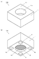
本開示の実施形態の加熱容器を、添付の図面を参照して説明する。図1は加熱容器100の外観を示しており、図1(a)は絶縁基体1の第1面11側(上面側)からの斜視図であり、図1(b)は絶縁基体1の第2面12側(下面側)からの斜視図である。図2は加熱容器100の一例を示しており、図2(a)は絶縁基体1の第1面11側(上面側)からの平面図(上面図)であり、図2(b)は図2(a)のB−B線における断面図であり、図2(c)は絶縁基体1の第2面12側(下面側)からの平面図(下面図)である。なお、以下の説明における上下の区別は便宜的なものであり、実際に加熱容器100が使用されるときの上下を限定するものではない。
The heating container of the embodiment of the present disclosure will be described with reference to the accompanying drawings. FIG. 1 shows the appearance of the heating container 100, FIG. 1 (a) is a perspective view from the first surface 11 side (upper surface side) of the insulating substrate 1, and FIG. 1 (b) is a first view of the insulating substrate 1. It is a perspective view from the 2 side 12 side (lower surface side). FIG. 2 shows an example of the heating container 100, FIG. 2A is a plan view (top view) from the first surface 11 side (upper surface side) of the insulating substrate 1, and FIG. 2B is a view. 2 (a) is a cross-sectional view taken along the line BB, and FIG. 2 (c) is a plan view (bottom view) from the second surface 12 side (lower surface side) of the insulating substrate 1. It should be noted that the distinction between the upper and lower parts in the following description is for convenience, and does not limit the upper and lower parts when the heating container 100 is actually used.
加熱容器100は、図1および図2に示す例のように、セラミックスからなる複数の絶縁層1aが積層されてなり、凹部11aを有する第1面11と第1面11と対向する第2面12とを有する絶縁基体1と、絶縁基体1の内部であって凹部11aと第2面12との間に設けられているヒータ2と、凹部11aと絶縁基体1の側面13との間において絶縁層1aを貫通し、凹部11aを取り囲むように配列されている複数の柱状伝熱体31を含む伝熱体3と、ヒータ2に接続されており、絶縁基体1の表面に設けられている端子電極4とを有している。
As shown in the examples shown in FIGS. 1 and 2, the heating container 100 is formed by laminating a plurality of insulating layers 1a made of ceramics, and has a first surface 11 having a recess 11a and a second surface facing the first surface 11. Insulation between the insulating substrate 1 having the 12 and the heater 2 provided between the recess 11a and the second surface 12 inside the insulating substrate 1 and the recess 11a and the side surface 13 of the insulating substrate 1. A terminal connected to the heater 2 and provided on the surface of the insulating substrate 1 and a heat transfer body 3 including a plurality of columnar heat transfer bodies 31 that penetrate the layer 1a and are arranged so as to surround the recess 11a. It has an electrode 4.
第1面11に凹部11aを有する絶縁基体1が試料を収容する容器本体である。絶縁基体1はセラミックスからなる複数の絶縁層1aが積層されてなるものであり、加熱容器100は、セラミック製の容器ということである。セラミックスは一般的に耐薬品性に優れているため、凹部11aに収容した試料によって容器が腐食したり、容器の成分が試料に溶出したりする可能性が極めて小さい。また、絶縁基体1の内部にはヒータ2が内蔵されており、ヒータ2は絶縁基体1の第2面12に設けられた端子電極4に電気的に接続されている。端子電極4を介して外部から電圧が印可されることでヒータ2が発熱し、その熱が絶縁基体1内を伝導して凹部11aに収容された試料を加熱することができる。容器にヒータ2が内蔵されているので、容器を外部から加熱するのに比較して容器内の試料を短時間で加熱することができる。加熱容器100は、セラミック製であるので耐熱性にも優れており、内蔵されているヒータ2が発熱しても、変質がほとんどなく、収容している試料へ溶出する可能性が極めて小さい。そして、加熱容器100は伝熱体3を備えている。
伝熱体3は、試料の入る凹部11aと絶縁基体1の側面13との間において絶縁層1aを貫通している複数の柱状伝熱体31を含んでいる。すなわち、試料の入る凹部11aを取り囲んで、絶縁基体1の内部に配列されている。言い換えれば、凹部11aを取り囲む側壁内に、凹部11aを取り囲むように複数の伝熱体3が配置されている。伝熱体3は、絶縁基体1よりも熱伝導率の高いものである。そのため、ヒータ2からの熱が凹部11aを取り囲む側壁にも伝わりやすくなり、凹部11aの内面の加熱効率、および凹部11aの内面における均熱性が高まる。凹部11aの周囲にもヒータを配置することでも加熱効率および均熱性の向上は可能である。しかしながら、その場合はヒータが長くなって抵抗が大きくなるので、所定の温度とするために印可する電流、電圧または時間を大きくしなければならない。これに対して上記構成であると、特に加熱容器100が小型で、ヒータ2に印可される電圧が低い場合でも効率よく加熱することができる。これにより、大きな加熱装置、加熱チャンバー等がなくてもよく、1つの試料の分析等に要する時間が短縮される。
The insulating substrate 1 having the recess 11a on the first surface 11 is the container body for accommodating the sample. The insulating substrate 1 is formed by laminating a plurality of insulating layers 1a made of ceramics, and the heating container 100 is a container made of ceramics. Since ceramics generally have excellent chemical resistance, it is extremely unlikely that the sample contained in the recess 11a will corrode the container or the components of the container will elute into the sample. Further, a heater 2 is built in the insulating substrate 1, and the heater 2 is electrically connected to a terminal electrode 4 provided on the second surface 12 of the insulating substrate 1. When a voltage is applied from the outside through the terminal electrode 4, the heater 2 generates heat, and the heat is conducted through the insulating substrate 1 to heat the sample housed in the recess 11a. Since the heater 2 is built in the container, the sample in the container can be heated in a short time as compared with heating the container from the outside. Since the heating container 100 is made of ceramic, it has excellent heat resistance, and even if the built-in heater 2 generates heat, there is almost no deterioration and the possibility of elution into the contained sample is extremely small. The heating container 100 includes a heat transfer body 3.
The heat transfer body 3 includes a plurality of columnar heat transfer bodies 31 penetrating the insulating layer 1a between the recess 11a into which the sample enters and the side surface 13 of the insulating substrate 1. That is, they are arranged inside the insulating substrate 1 so as to surround the recess 11a in which the sample enters. In other words, in the side wall surrounding the recess 11a, a plurality of heat transfer bodies 3 are arranged so as to surround the recess 11a. The heat transfer body 3 has a higher thermal conductivity than the insulating substrate 1. Therefore, the heat from the heater 2 is easily transferred to the side wall surrounding the recess 11a, and the heating efficiency of the inner surface of the recess 11a and the soaking property on the inner surface of the recess 11a are enhanced. It is also possible to improve the heating efficiency and heat soaking property by arranging a heater around the recess 11a. However, in that case, the heater becomes long and the resistance becomes large, so that the current, voltage, or time to be applied must be increased in order to obtain a predetermined temperature. On the other hand, with the above configuration, even when the heating container 100 is particularly small and the voltage applied to the heater 2 is low, it can be efficiently heated. This eliminates the need for a large heating device, heating chamber, etc., and shortens the time required for analysis of one sample.
図2に示す例においては、10層の絶縁層1aが積層されて絶縁基体1が構成されている。より具体的には、6層の絶縁層1aで凹部11aの側壁が構成され、凹部11aと第2面12との間は4層の絶縁層1aで構成されている。絶縁層1aの平面視の形状は正方形であり、第1面11側の6層の絶縁層1aは円形の貫通孔を備えている。これによって、絶縁基体1は、複数の絶縁層1aが積層されてなる全体的な形状が直方体であり、凹部11aを有する第1面11と第1面11と対向する第2面12とを有するものとなっている。絶縁層1aの形状および層数はこの例に限られるものではなく、絶縁基体1および凹部11aの形状もこれに限られるものではない。平面視形状が正方形の絶縁基体1に対して、同じく平面視形状が正方形の凹部11aを設けてもよいし、平面視形状が円形の絶縁基体1に対して、同じく平面視形状が円形の凹部11aを設けてもよい。絶縁基体1および凹部11aともに、その他の多角形状や楕円状であってもよい。図1および図2に示す例のように凹部11aの平面視の形状が円形であると、試料が液状である場合には、凹部11a内において試料の対流が均質なものになりやすいので、試料の温度の均熱性を高めることができる。
In the example shown in FIG. 2, 10 insulating layers 1a are laminated to form the insulating substrate 1. More specifically, the side wall of the recess 11a is formed by the six layers of the insulating layer 1a, and the space between the recess 11a and the second surface 12 is formed by the four layers of the insulating layer 1a. The shape of the insulating layer 1a in a plan view is square, and the six insulating layers 1a on the first surface 11 side have circular through holes. As a result, the insulating substrate 1 has a rectangular parallelepiped overall shape in which a plurality of insulating layers 1a are laminated, and has a first surface 11 having a recess 11a and a second surface 12 facing the first surface 11. It has become a thing. The shape and number of layers of the insulating layer 1a are not limited to this example, and the shapes of the insulating substrate 1 and the recess 11a are not limited to this. A recess 11a having a square plan view may be provided on the insulating substrate 1 having a square plan view, or a recess having a circular plan view shape may be provided on the insulating substrate 1 having a circular plan view shape. 11a may be provided. Both the insulating substrate 1 and the recess 11a may have other polygonal shapes or elliptical shapes. When the shape of the concave portion 11a in a plan view is circular as in the examples shown in FIGS. 1 and 2, when the sample is liquid, the convection of the sample tends to be uniform in the concave portion 11a, so that the sample is sampled. It is possible to increase the soaking property of the temperature of.
ヒータ2は、絶縁基体1の内部における凹部11aと絶縁基体1の第2面(下面)12との間に位置する絶縁層1a間に設けられている。図2(b)に示す例では、ヒータ2は第2面12よりも凹部11a(の底面)の方に近い位置に設けられている。ヒータ2aと凹部11aとの間の絶縁層1aの数と、ヒータ2aと第2面12との間の絶縁層1aの数とは同じく2つであるが、これら4つの絶縁層1aのうち最も第2面12側の絶縁層1aの厚みはそれ以外の絶縁層1aの厚みよりも厚いためである。このようにすると、ヒータ2で発生した熱が凹部11aへより伝わりやすくなるので、凹部11a内の試料の加熱効
率のよい加熱容器100となる。
The heater 2 is provided between the insulating layer 1a located between the recess 11a inside the insulating substrate 1 and the second surface (lower surface) 12 of the insulating substrate 1. In the example shown in FIG. 2B, the heater 2 is provided at a position closer to (the bottom surface) of the recess 11a than the second surface 12. The number of the insulating layers 1a between the heater 2a and the recess 11a and the number of the insulating layers 1a between the heater 2a and the second surface 12 are the same, but the number of the insulating layers 1a among these four insulating layers 1a is the largest. This is because the thickness of the insulating layer 1a on the second surface 12 side is thicker than the thickness of the other insulating layers 1a. By doing so, the heat generated by the heater 2 is more easily transferred to the recess 11a, so that the heating container 100 has good heating efficiency of the sample in the recess 11a.
ヒータ2の平面透視における形状は、例えば図2(c)に示す例のような、線状の導体が複数回折れ曲がって蛇行している、いわゆるミアンダ形状である。ヒータ2は、少なくとも平面透視で凹部11aと重なるように配置されていれば凹部11aの底面および凹部11a内の試料を効率よく加熱することができる。より効率よく加熱するためには、図2(c)に示す例のように絶縁基体1の内部(絶縁層1a間)においてできるだけ広い範囲に設けるとよく、図2(c)に絶縁層1aを透過して破線で示しているように、平面透視で凹部11aと重なる部分からその周囲にわたって設けられている。言い換えれば、平面透視で凹部11aおよび凹部11aを取り囲む側壁と重なるようにヒータ2が設けられている。また、ヒータ2は、平面透視で伝熱体3(柱状伝熱体31)とも一部が重なっている。そのため、ヒータ2から凹部11aの内側面へ熱が伝わりやすくなっている。
The shape of the heater 2 in plan perspective is a so-called meander shape in which a plurality of linear conductors are bent and meandered, as in the example shown in FIG. 2 (c), for example. The heater 2 can efficiently heat the bottom surface of the recess 11a and the sample in the recess 11a if the heater 2 is arranged so as to overlap the recess 11a at least in a plan view. In order to heat more efficiently, it is preferable to provide the insulating layer 1a in as wide a range as possible inside the insulating substrate 1 (between the insulating layers 1a) as in the example shown in FIG. 2C, and the insulating layer 1a is provided in FIG. 2C. As shown by the transparent broken line, it is provided from the portion overlapping the recess 11a in the plan perspective to the periphery thereof. In other words, the heater 2 is provided so as to overlap the recess 11a and the side wall surrounding the recess 11a in plan perspective. Further, the heater 2 partially overlaps with the heat transfer body 3 (columnar heat transfer body 31) in a planar perspective. Therefore, heat is easily transferred from the heater 2 to the inner surface of the recess 11a.
伝熱体3(柱状伝熱体31)は、凹部11aを取り囲むように、11aと絶縁基体1の
側面13との間すなわち側壁内に配置されている。図2に示す例においては、加熱容器100は24個の伝熱体3(柱状伝熱体31)を備えているが、これに限られるものではない。また、図2に示す例においては、同じ大きさの伝熱体3(柱状伝熱体31)が、凹部11a(の内側面)からの距離が一定の位置に等間隔に配置されている。これにより、凹部11aの内面における均熱性が高いものとなる。
The heat transfer body 3 (columnar heat transfer body 31) is arranged between the 11a and the side surface 13 of the insulating substrate 1, that is, in the side wall so as to surround the recess 11a. In the example shown in FIG. 2, the heating container 100 includes 24 heat transfer bodies 3 (columnar heat transfer bodies 31), but is not limited thereto. Further, in the example shown in FIG. 2, heat transfer bodies 3 (columnar heat transfer bodies 31) having the same size are arranged at equal intervals at positions where the distance from the recess 11a (inner side surface) is constant. As a result, the heat equalizing property on the inner surface of the recess 11a becomes high.
また、伝熱体3(柱状伝熱体31)は、図2に示す例においては、側壁内から凹部11aの底面よりも絶縁基体1の第2面12側へ伸びている。これにより、凹部11aの底面より絶縁基体1の第2面12側に位置しているヒータ2との距離が短くなるので、ヒータ2から伝熱体(柱状伝熱体31)への伝熱効率が高いものとなる。また、側壁内において、伝熱体3(柱状伝熱体31)は絶縁基体1の側面13より凹部11a(の内側面)に近い位置に配置されている。これにより、ヒータ2から凹部11aの内側面への伝熱効率がより高まる。
Further, in the example shown in FIG. 2, the heat transfer body 3 (columnar heat transfer body 31) extends from the inside of the side wall toward the second surface 12 side of the insulating substrate 1 from the bottom surface of the recess 11a. As a result, the distance from the bottom surface of the recess 11a to the heater 2 located on the second surface 12 side of the insulating substrate 1 becomes shorter, so that the heat transfer efficiency from the heater 2 to the heat transfer body (columnar heat transfer body 31) becomes shorter. It will be expensive. Further, in the side wall, the heat transfer body 3 (columnar heat transfer body 31) is arranged at a position closer to the recess 11a (inner side surface) than the side surface 13 of the insulating substrate 1. As a result, the heat transfer efficiency from the heater 2 to the inner surface of the recess 11a is further enhanced.
柱状伝熱体31は、図2に示す例では円柱状の伝熱体3である。柱状伝熱体31は横断面形状が円形の円柱状に限られず、横断面形状は四角形や六角形等の多角形状であってもよいし、楕円形状であってもよい。また、断面の大きさが一定の厳密な柱状でなく、例えば円錐台、鼓型、樽型のような長さ方向で径(断面積)が異なっているものも含む。また、複数の柱状伝熱体31の断面積(円柱の場合であれば径)は同じものでなくてもよい。例えば、第2面12側から第1面11側に向かうにつれて、絶縁層1a毎に柱状伝熱体31の断面積が大きくなるものとすることができる。側壁内において複数の絶縁層1aを貫通する柱状伝熱体31として見たときに、第2面12側から第1面11側に向かうにつれて、絶縁層1a毎に柱状伝熱体31の断面積が大きくなっていてもよい。すなわち、例えば、柱状伝熱体31を第1面11側の径の方が大きい円錐台状とし、隣接する絶縁層1a間において、第1面11側の絶縁層1a内の柱状伝熱体31の端(下端)の径と第2面12側の絶縁層1a内の柱状伝熱体31の端(上端)の径とを同程度とすることができる。このようにすることで、第2面12側から第1面11側への伝熱効率を向上させることができる。
The columnar heat transfer body 31 is a columnar heat transfer body 3 in the example shown in FIG. The columnar heat transfer body 31 is not limited to a columnar shape having a circular cross-sectional shape, and the cross-sectional shape may be a polygonal shape such as a quadrangle or a hexagon, or an elliptical shape. It also includes those having different diameters (cross-sectional areas) in the length direction, such as a truncated cone, a drum shape, and a barrel shape, rather than a strict columnar shape having a constant cross-sectional size. Further, the cross-sectional areas (diameters in the case of columns) of the plurality of columnar heat transfer bodies 31 do not have to be the same. For example, the cross-sectional area of the columnar heat transfer body 31 can be increased for each insulating layer 1a from the second surface 12 side to the first surface 11 side. When viewed as a columnar heat transfer body 31 penetrating a plurality of insulating layers 1a in the side wall, the cross-sectional area of the columnar heat transfer body 31 for each insulating layer 1a as it goes from the second surface 12 side to the first surface 11 side. May be larger. That is, for example, the columnar heat transfer body 31 has a truncated cone shape having a larger diameter on the first surface 11 side, and the columnar heat transfer body 31 in the insulating layer 1a on the first surface 11 side between adjacent insulating layers 1a. The diameter of the end (lower end) of the columnar heat transfer body 31 in the insulating layer 1a on the second surface 12 side can be made the same as the diameter of the end (upper end) of the columnar heat transfer body 31. By doing so, the heat transfer efficiency from the second surface 12 side to the first surface 11 side can be improved.
端子電極4は、図1および図2に示す例では、絶縁基体1の第2面12に設けられている。端子電極4は、外部回路と接続することができる位置にあればよく、絶縁基体1の表面に設けられていればよい。端子電極4の接続先の形状等に応じて、配置や形状を設定すればよい。例えば、絶縁基体1の表面に試料を入れるための凹部11a以外の凹部を設けて、その内面に端子電極4を配置してもよい。あるいは、例えば第2面12から側面にかけて設けることもできる。
The terminal electrode 4 is provided on the second surface 12 of the insulating substrate 1 in the examples shown in FIGS. 1 and 2. The terminal electrode 4 may be located at a position where it can be connected to an external circuit, and may be provided on the surface of the insulating substrate 1. The arrangement and shape may be set according to the shape and the like of the connection destination of the terminal electrode 4. For example, a recess other than the recess 11a for inserting the sample may be provided on the surface of the insulating substrate 1, and the terminal electrode 4 may be arranged on the inner surface thereof. Alternatively, for example, it may be provided from the second surface 12 to the side surface.
端子電極4は、ヒータ2に電気的に接続されている。ヒータ2の両端がそれぞれ端子電極4に接続されるので、少なくとも2つの端子電極4が絶縁基体1の表面に設けられる。端子電極4とヒータ2とは、絶縁基体1に設けた内部配線4aによって電気的に接続される。図2に示す例においては、内部配線4aは2つの貫通導体と1つの層間導体とで構成されている。より具体的には、ヒータ2と第2面12との間に位置する絶縁層1a間に層間導体が設けられ、ヒータ2と層間導体および層間導体と端子電極4とがそれぞれ貫通導体で接続されている。内部配線4aはこのような構成に限られるものではない。例えば、端子電極4が、ヒータ2の両端部のそれぞれと平面透視で重なる位置に設けられている場合には、内部配線4aを1つの貫通導体で構成することができる。また、端子電極4の少なくとも一部が絶縁基体1の側面に設けられている場合であれば、内部配線4aを1つの層間導体で構成することができる。
The terminal electrode 4 is electrically connected to the heater 2. Since both ends of the heater 2 are connected to the terminal electrodes 4, at least two terminal electrodes 4 are provided on the surface of the insulating substrate 1. The terminal electrode 4 and the heater 2 are electrically connected by an internal wiring 4a provided on the insulating substrate 1. In the example shown in FIG. 2, the internal wiring 4a is composed of two through conductors and one interlayer conductor. More specifically, an interlayer conductor is provided between the insulating layer 1a located between the heater 2 and the second surface 12, and the heater 2 and the interlayer conductor and the interlayer conductor and the terminal electrode 4 are connected by a through conductor, respectively. ing. The internal wiring 4a is not limited to such a configuration. For example, when the terminal electrode 4 is provided at a position where it overlaps each of both ends of the heater 2 in a plane perspective, the internal wiring 4a can be configured by one through conductor. Further, if at least a part of the terminal electrode 4 is provided on the side surface of the insulating substrate 1, the internal wiring 4a can be composed of one interlayer conductor.
図1および図2に示す例では、絶縁基体1の第2面12には、2つの端子電極4以外に2つのダミー端子4bが設けられている。これは必ずしも必要なものではない。例えば、
加熱容器100を外部回路基板等に接続固定する際に、ダミー端子4を備えていると、4点で接続固定されるので加熱容器100を外部回路基板等の上で傾くことなく固定しやすくなる。
In the example shown in FIGS. 1 and 2, the second surface 12 of the insulating substrate 1 is provided with two dummy terminals 4b in addition to the two terminal electrodes 4. This is not always necessary. for example,
When the heating container 100 is connected and fixed to the external circuit board or the like, if the dummy terminal 4 is provided, the heating container 100 is connected and fixed at four points, so that the heating container 100 can be easily fixed without tilting on the external circuit board or the like. ..
図3は加熱容器100の他の例を示しており、図3(a)は絶縁基体1の第1面11側(上面側)からの平面図(上面図)であり、図3(b)は図3(a)のB−B線における断面図である。この例において図2に示す例と異なる点は、伝熱体3が、環状伝熱体32をさらに含んでいる点である。環状伝熱体32は、凹部11aと側面13との間の絶縁層1aの層間に設けられており、柱状伝熱体31と接続されている。環状伝熱体32の平面視の形状は環状であり、凹部11aを取り囲むように配置されている。ここでいう環状とは、凹部11aを取り囲むような形状のことであり、図3に示す例のような厳密な円形のものだけでなく、例えば四角形状である枠状のものも含む。凹部11aの平面視の形状に沿った形状であればよく、凹部11aの平面視の形状に対して一回り大きい相似形の貫通孔(開口)を有するものである。
FIG. 3 shows another example of the heating container 100, FIG. 3 (a) is a plan view (top view) from the first surface 11 side (upper surface side) of the insulating substrate 1, and FIG. 3 (b) is shown. Is a cross-sectional view taken along the line BB of FIG. 3 (a). The difference in this example from the example shown in FIG. 2 is that the heat transfer body 3 further includes the annular heat transfer body 32. The annular heat transfer body 32 is provided between the layers of the insulating layer 1a between the recess 11a and the side surface 13, and is connected to the columnar heat transfer body 31. The shape of the annular heat transfer body 32 in a plan view is annular, and is arranged so as to surround the recess 11a. The annular shape referred to here is a shape that surrounds the recess 11a, and includes not only a strict circular shape as in the example shown in FIG. 3 but also a frame shape that is, for example, a quadrangular shape. The shape may be any shape that follows the shape of the recess 11a in a plan view, and has a similar through hole (opening) that is one size larger than the shape of the recess 11a in a plan view.
このような環状伝熱体32により、側壁内において絶縁層1aの積層方向に対して垂直な方向、絶縁層1aの面方向にも熱が伝わりやすくなるので、凹部11aの内側面の周方向においてより均熱化しやすくなる。また、環状伝熱体32は、柱状伝熱体31より内側に伸びる部分を有しているので、柱状伝熱体31から凹部11aの内側面への伝熱効率を向上させることもできる。
With such an annular heat transfer body 32, heat is easily transferred in the side wall in the direction perpendicular to the stacking direction of the insulating layer 1a and also in the surface direction of the insulating layer 1a, so that heat is easily transferred in the circumferential direction of the inner surface of the recess 11a. It becomes easier to equalize the heat. Further, since the annular heat transfer body 32 has a portion extending inward from the columnar heat transfer body 31, the heat transfer efficiency from the columnar heat transfer body 31 to the inner surface of the recess 11a can be improved.
図3に示す例においては、ヒータ2が設けられている絶縁層1a間より第1面11側に位置している7つの絶縁層1a間のすべてに環状伝熱体32が設けられている。絶縁層1aの積層方向に隣接する環状伝熱体32の間には柱状伝熱体31が設けられており、柱状伝熱体31の両端部のそれぞれが環状伝熱体32に接続されている。ヒータ2で発生した熱は、伝熱体3において最もヒータ2に近い位置にある環状伝熱体32に伝わる。環状伝熱体32は柱状伝熱体31より絶縁層1aの面方向に広がっており、平面透視でヒータ2と重なる面積が大きい。そのため、伝熱体3が柱状伝熱体31だけで構成されている場合に比較して、ヒータ2から伝熱体3への伝熱効率が向上する。また、上記したように環状伝熱体32によって絶縁層1aの面方向にも熱を伝えることができるので、ヒータ2の直上に位置していない柱状伝熱体31への伝熱も効率よく行なわれ、第1面11側への伝熱効率が向上する。
In the example shown in FIG. 3, the annular heat transfer body 32 is provided in all of the seven insulating layers 1a located on the first surface 11 side of the insulating layer 1a in which the heater 2 is provided. A columnar heat transfer body 31 is provided between the annular heat transfer bodies 32 adjacent to each other in the stacking direction of the insulating layer 1a, and both ends of the columnar heat transfer body 31 are connected to the annular heat transfer body 32. .. The heat generated by the heater 2 is transferred to the annular heat transfer body 32 located at the position closest to the heater 2 in the heat transfer body 3. The annular heat transfer body 32 extends in the plane direction of the insulating layer 1a from the columnar heat transfer body 31, and has a large area overlapping with the heater 2 in plan perspective. Therefore, the heat transfer efficiency from the heater 2 to the heat transfer body 3 is improved as compared with the case where the heat transfer body 3 is composed of only the columnar heat transfer body 31. Further, as described above, heat can be transferred to the surface direction of the insulating layer 1a by the annular heat transfer body 32, so that heat can be efficiently transferred to the columnar heat transfer body 31 which is not located directly above the heater 2. As a result, the heat transfer efficiency to the first surface 11 side is improved.
また、図3に示す例においては、環状伝熱体32の幅方向における中心より外側において柱状伝熱体31が接続されている。言い換えれば、環状伝熱体32は、柱状伝熱体31が接続された部分より内側(凹部11a側)の幅の方が、柱状伝熱体31が接続された部分より外側(側面13側)の幅の方より大きい。さらに言えば、環状伝熱体32は、柱状伝熱体31が接続された部分から凹部11a側へより長く伸びている。これにより、より凹部11aへの伝熱性を高めることができる。
Further, in the example shown in FIG. 3, the columnar heat transfer body 31 is connected outside the center in the width direction of the annular heat transfer body 32. In other words, the width of the annular heat transfer body 32 inside (the recess 11a side) is wider than the portion to which the columnar heat transfer body 31 is connected, and the width is outside (side surface 13 side) of the portion to which the columnar heat transfer body 31 is connected. Larger than the width of. Furthermore, the annular heat transfer body 32 extends longer from the portion to which the columnar heat transfer body 31 is connected toward the recess 11a side. Thereby, the heat transfer property to the recess 11a can be further enhanced.
環状伝熱体32の幅は、図3に示す例では、環状伝熱体32が設けられた位置によらず、複数の環状伝熱体32間で同じである。これに限られるものではなく、例えば後述する図5に示す例のように、第1面11側に位置する環状伝熱体32の幅を第2面12側に位置する環状伝熱体32の幅より大きくすることができる。さらに言えば、環状伝熱体32の、柱状伝熱体31が接続された部分より内側(凹部11a側)の幅が第1面11に近いものほど大きい伝熱体3とすることができる。言い換えれば、環状伝熱体32の内終端と凹部11a(の内側面)との距離が、第1面11に近いものほど小さい伝熱体3とすることができる。図5に示す例では、第1面11に近づくにつれて環状伝熱体32の内終端と凹部11aの内側面との距離が小さくなるように、環状伝熱体32の2つずつ幅が大きくなっている。第1面11に近いほどヒータ2から離れているので、環状伝熱体32の内終
端を凹部11a(の内側面)に近付けて熱が凹部11aの内側面に伝わりやすくすることで、凹部11aの内側面における温度分布を小さくすることができる。
In the example shown in FIG. 3, the width of the annular heat transfer body 32 is the same among the plurality of annular heat transfer bodies 32 regardless of the position where the annular heat transfer body 32 is provided. The width of the annular heat transfer body 32 located on the first surface 11 side is set to the width of the annular heat transfer body 32 located on the second surface 12 side, for example, as shown in FIG. 5 described later. It can be larger than the width. Further, the heat transfer body 3 can be made larger as the width of the annular heat transfer body 32 is closer to the first surface 11 on the inner side (recessed portion 11a side) than the portion to which the columnar heat transfer body 31 is connected. In other words, the heat transfer body 3 can be made smaller as the distance between the inner end of the annular heat transfer body 32 and the recess 11a (inner side surface) is closer to the first surface 11. In the example shown in FIG. 5, the width of the annular heat transfer body 32 increases by two so that the distance between the inner end of the annular heat transfer body 32 and the inner surface of the recess 11a decreases as the first surface 11 approaches. ing. The closer it is to the first surface 11, the farther it is from the heater 2, so that the inner end of the annular heat transfer body 32 is brought closer to (the inner surface) of the recess 11a to facilitate heat transfer to the inner surface of the recess 11a. The temperature distribution on the inner surface of the can be reduced.
ここで、図4(a)および図4(b)はいずれも加熱容器100の伝熱体3の構成の一例を示す斜視図である。図3に示す例では、伝熱体3が7つの環状伝熱体32と環状伝熱体32間に位置する6つの絶縁層1aを貫通する6段の柱状伝熱体31とを備えているのに対して、図4(a)および図4(b)に示す例では、5つの環状伝熱体32と環状伝熱体32間の4段の柱状伝熱体31で構成された伝熱体3を示している。また、図3に示す例では1つの絶縁層1aに設けられている柱状伝熱体31は24個であるのに対して、図4に示す例では12個である。
Here, both FIGS. 4A and 4B are perspective views showing an example of the configuration of the heat transfer body 3 of the heating container 100. In the example shown in FIG. 3, the heat transfer body 3 includes seven annular heat transfer bodies 32 and a six-stage columnar heat transfer body 31 penetrating six insulating layers 1a located between the annular heat transfer bodies 32. On the other hand, in the example shown in FIGS. 4 (a) and 4 (b), the heat transfer body is composed of the five columnar heat transfer bodies 31 between the five annular heat transfer bodies 32 and the annular heat transfer bodies 32. Shows body 3. Further, in the example shown in FIG. 3, the number of columnar heat transfer bodies 31 provided in one insulating layer 1a is 24, whereas in the example shown in FIG. 4, it is 12.
図2、図3および図4(a)に示す例においては、柱状伝熱体31は平面透視で重なるように配置されている。言い換えれば、柱状伝熱体31は複数の絶縁層1aを積層方向に直線的に貫通している。そのため、側壁内における積層方向の伝熱経路は一直線状となり短いものとなるので、ヒータ2から第1面11側への伝熱効率が高いものである。一方で、側壁の各絶縁層1a内においては、柱状伝熱体31の近傍と柱状伝熱体31間とでは少なからず温度差が生じてしまう。この温度差は凹部11aの内側面において温度分布として現れることになる。この凹部11aの内側面における温度分布を小さくするには、絶縁層1aの面方向における柱状伝熱体31の間隔をできるだけ小さくすればよい。しかしながら、この間隔が小さすぎると柱状伝熱体31間における絶縁層1aにクラックが発生してしまう可能性が高くなってしまう。
In the examples shown in FIGS. 2, 3 and 4 (a), the columnar heat transfer bodies 31 are arranged so as to overlap each other in a plane perspective. In other words, the columnar heat transfer body 31 penetrates the plurality of insulating layers 1a linearly in the stacking direction. Therefore, the heat transfer path in the stacking direction in the side wall is straight and short, so that the heat transfer efficiency from the heater 2 to the first surface 11 side is high. On the other hand, in each insulating layer 1a of the side wall, there is not a little temperature difference between the vicinity of the columnar heat transfer body 31 and the columnar heat transfer body 31. This temperature difference will appear as a temperature distribution on the inner surface of the recess 11a. In order to reduce the temperature distribution on the inner surface of the recess 11a, the distance between the columnar heat transfer bodies 31 in the surface direction of the insulating layer 1a may be as small as possible. However, if this interval is too small, there is a high possibility that cracks will occur in the insulating layer 1a between the columnar heat transfer bodies 31.
これに対して、図4(b)に示す例では、環状伝熱体32を挟んでいる2つの絶縁層1a間で、柱状伝熱体31は平面透視で重ならないで配置されている。言い換えれば、1つの絶縁層1a内に設けられている環状伝熱体32は、隣接する絶縁層1a内の環状伝熱体32とは積層方向で一直線上に位置していない。そのため、ヒータ2から第1面11側への伝熱体3内の伝熱経路は、環状伝熱体32を介するものとなるので、側壁内において絶縁層1aの面方向への伝熱が促進される。結果として、凹部1aの内側面における温度分布が小さくなり、凹部1a内の試料の加熱もばらつきの小さいものとすることができる。
On the other hand, in the example shown in FIG. 4B, the columnar heat transfer bodies 31 are arranged so as not to overlap each other in a plane perspective between the two insulating layers 1a sandwiching the annular heat transfer body 32. In other words, the annular heat transfer body 32 provided in one insulating layer 1a is not located in a straight line with the annular heat transfer body 32 in the adjacent insulating layer 1a in the stacking direction. Therefore, the heat transfer path in the heat transfer body 3 from the heater 2 to the first surface 11 side is via the annular heat transfer body 32, so that heat transfer in the surface direction of the insulating layer 1a is promoted in the side wall. Will be done. As a result, the temperature distribution on the inner surface of the recess 1a becomes small, and the heating of the sample in the recess 1a can be made small in variation.
図5は加熱容器100の他の例を示しており、図5(a)は第1面側からの平面図(上面図)であり、図5(b)は図5(a)のB−B線における断面図である。この例は、図3に示す例に対して、最も第2面12側、ヒータ2に最も近い環状伝熱体32を円板状の板状伝熱体33に置き換えた例である。
5A and 5B show another example of the heating container 100, FIG. 5A is a plan view (top view) from the first surface side, and FIG. 5B is B- of FIG. 5A. It is sectional drawing in B line. This example is an example in which the annular heat transfer body 32 closest to the heater 2 on the second surface 12 side is replaced with a disk-shaped plate heat transfer body 33 with respect to the example shown in FIG.
図5に示す例の加熱容器100のように、ヒータ2と凹部11aとの間に位置する絶縁層1aの層間に板状伝熱体33を有し、板状伝熱体33と柱状伝熱体31とが接続されているものとすることができる。板状伝熱体33の外縁部は平面透視で側壁と重なり、柱状伝熱体31が接続されている。また、板状伝熱体33の中央部は平面透視で凹部11aと重なり、凹部11aの底面と絶縁層1aを挟んで対向している。図3における、最もヒータ2に近い環状伝熱体32の貫通孔をなくして円板状にしたともいうことができる。
Like the heating container 100 of the example shown in FIG. 5, the plate-shaped heat transfer body 33 is provided between the layers of the insulating layer 1a located between the heater 2 and the recess 11a, and the plate-shaped heat transfer body 33 and the columnar heat transfer body are provided. It can be assumed that the body 31 is connected. The outer edge portion of the plate-shaped heat transfer body 33 overlaps the side wall in a plane perspective, and the columnar heat transfer body 31 is connected to the side wall. Further, the central portion of the plate-shaped heat transfer body 33 overlaps with the recess 11a in a plane perspective, and faces the bottom surface of the recess 11a with the insulating layer 1a interposed therebetween. It can also be said that the through hole of the annular heat transfer body 32 closest to the heater 2 in FIG. 3 is eliminated to form a disk.
凹部11aの底面に対向して設けられたヒータ2が線状であると、凹部11aの底面において平面透視でヒータ2と重なる部分と重ならない部分とで温度差ができる場合がある。これに対して、伝熱体3が上記のような板状伝熱体33を備えていると、ヒータ2から板状伝熱体33に伝わった熱は、板状伝熱体33内で絶縁層1aの面方向に拡散して凹部11aの底面へと伝わるようになる。そのため、凹部11aの底面における温度分布が小さく均熱性が向上する。また、絶縁基体1の平面視における中央部に位置するヒータ2で発生した熱が、板状伝熱体33を介して側壁内の柱状伝熱体31に伝熱しやすくなるので、凹部11aの内側面の加熱効率、および凹部11aの内面における均熱性が高まる。
If the heater 2 provided so as to face the bottom surface of the recess 11a is linear, there may be a temperature difference between the portion of the bottom surface of the recess 11a that overlaps with the heater 2 and the portion that does not overlap with the heater 2. On the other hand, when the heat transfer body 3 includes the plate-shaped heat transfer body 33 as described above, the heat transferred from the heater 2 to the plate-shaped heat transfer body 33 is insulated in the plate-shaped heat transfer body 33. It diffuses in the surface direction of the layer 1a and is transmitted to the bottom surface of the recess 11a. Therefore, the temperature distribution on the bottom surface of the recess 11a is small and the heat soaking property is improved. Further, the heat generated by the heater 2 located in the central portion of the insulating substrate 1 in the plan view is easily transferred to the columnar heat transfer body 31 in the side wall via the plate-shaped heat transfer body 33, so that the heat is easily transferred to the inside of the recess 11a. The heating efficiency of the side surface and the soaking property on the inner surface of the recess 11a are enhanced.
図6は加熱容器100の他の一例の外観を示しており、図6(a)は第1面11側(上面側)からの斜視図であり、図6(b)は第2面12側(下面側)からの斜視図である。図7は図6に示す加熱容器100を示しており、図7(a)は第2面12側(下面側)からの平面図(下面図)であり、図7(b)は断面図である。図8〜図11は、いずれも加熱容器100の他の一例を示しており、それぞれの図における(a)は第2面12側(下面側)からの平面図(下面図)であり、(b)は断面図である。なお、図11(a)においては、平面図であるが区別しやすいように低熱伝導部14にドット状の網掛けを施している。これら図6〜図11に示す例と上記した例とで異なる点は、ヒータ2と第2面12との間に絶縁層1aより熱伝導率の小さい低熱伝導部14をさらに含んでいる点である。
6A and 6B show the appearance of another example of the heating container 100, FIG. 6A is a perspective view from the first surface 11 side (upper surface side), and FIG. 6B is the second surface 12 side. It is a perspective view from (lower surface side). 7 shows the heating container 100 shown in FIG. 6, FIG. 7A is a plan view (bottom view) from the second surface 12 side (lower surface side), and FIG. 7B is a cross-sectional view. be. 8 to 11 each show another example of the heating container 100, and (a) in each figure is a plan view (bottom view) from the second surface 12 side (lower surface side), and ( b) is a cross-sectional view. In addition, in FIG. 11A, although it is a plan view, the low heat conductive portion 14 is shaded in a dot shape so as to be easy to distinguish. The difference between the examples shown in FIGS. 6 to 11 and the above-mentioned example is that a low thermal conductivity portion 14 having a thermal conductivity smaller than that of the insulating layer 1a is further included between the heater 2 and the second surface 12. be.
加熱容器100がヒータ2と絶縁基体1の第2面12との間に絶縁層1aより熱伝導率が小さい低熱伝導部14をさらに含む場合には、ヒータ2より第1面11側の方がヒータ2より第2面12側より熱伝導率が大きくなるので、ヒータ2で発生した熱は第1面11側へ伝導しやすくなる。よって、ヒータ2より第1面11側に位置する凹部11aおよび伝熱体3へ熱が伝わりやすくなるので、凹部11aの内側面、すなわち凹部11a内の試料の加熱効率がより高い加熱容器100となる。
When the heating container 100 further includes a low thermal conductive portion 14 having a thermal conductivity smaller than that of the insulating layer 1a between the heater 2 and the second surface 12 of the insulating substrate 1, the first surface 11 side is closer to the heater 2. Since the thermal conductivity is higher than that of the heater 2 on the second surface 12 side, the heat generated by the heater 2 is easily conducted to the first surface 11 side. Therefore, heat is easily transferred to the recess 11a and the heat transfer body 3 located on the first surface 11 side of the heater 2, so that the heating efficiency of the sample in the inner surface of the recess 11a, that is, the recess 11a is higher than that of the heating container 100. Become.
低熱伝導部14は、絶縁層1aよりも熱伝導率の小さい材料で構成されている。例えば、低熱伝導部14の材料が空気等の気体とすることができる。すなわち、低熱伝導部14は、全体が空隙部分であり、絶縁基体1に設けられた空間とすることができる。図6および図7に示す例では、絶縁基体1の第2面12からヒータ2まで絶縁層1aを貫通する凹部が設けられており、この凹部内の空間が低熱伝導部14である。ヒータ2の一部はこの凹部の内面に露出しており、ヒータ2と低熱伝導部14との間に絶縁層1aが介在しておらず、ヒータ2の第1面11側は絶縁層1aに接し、第2面12側は熱伝導率の小さい低熱伝導部14に接している。ヒータ2を挟んで位置する絶縁層1aと低熱伝導部14とで熱伝導率の差が大きいので、ヒータ2からの熱は、絶縁層1a側、すなわち第1面11側、凹部11aへ伝導しやすくなる。
The low thermal conductivity portion 14 is made of a material having a thermal conductivity lower than that of the insulating layer 1a. For example, the material of the low heat conductive portion 14 can be a gas such as air. That is, the low heat conductive portion 14 is a void portion as a whole, and can be a space provided in the insulating substrate 1. In the examples shown in FIGS. 6 and 7, a recess is provided from the second surface 12 of the insulating substrate 1 to the heater 2 so as to penetrate the insulating layer 1a, and the space in the recess is the low heat conductive portion 14. A part of the heater 2 is exposed on the inner surface of this recess, the insulating layer 1a is not interposed between the heater 2 and the low thermal conductive portion 14, and the first surface 11 side of the heater 2 is the insulating layer 1a. The second surface 12 side is in contact with the low thermal conductivity portion 14 having a small thermal conductivity. Since the difference in thermal conductivity between the insulating layer 1a located sandwiching the heater 2 and the low thermal conductive portion 14 is large, the heat from the heater 2 is conducted to the insulating layer 1a side, that is, the first surface 11 side and the recess 11a. It will be easier.
図8に示す例では、絶縁基体1の第2面12からヒータ2までの間の途中までの絶縁層1aを貫通する、より詳細にはヒータ2と第2面12の間の2層の絶縁層1aのうち、第2面12側の絶縁層1aだけを貫通する凹部が設けられている。言い換えれば、絶縁基体1の第2面12からの深さが、第2面12からヒータ2までの距離より小さい凹部が設けられており、この凹部内の空間が低熱伝導部14である。図6および図7に示す例に比較すると、ヒータ2からの熱は第2面12へ伝熱しやすくなるが、絶縁基体1の剛性が高くなるので、強度の高い加熱容器100となる。また、この例では凹部内にヒータ2が露出しておらず、ヒータ2の表面は絶縁層1aに覆われている。そのため、ヒータ2が外部の雰囲気等にさらされることがないので耐腐食性が向上し、安定した加熱が可能となる。
In the example shown in FIG. 8, the two layers of insulation between the heater 2 and the second surface 12 penetrate the insulating layer 1a halfway between the second surface 12 and the heater 2 of the insulating substrate 1. Of the layers 1a, a recess is provided that penetrates only the insulating layer 1a on the second surface 12 side. In other words, a recess is provided in which the depth of the insulating substrate 1 from the second surface 12 is smaller than the distance from the second surface 12 to the heater 2, and the space inside the recess is the low heat conductive portion 14. Compared with the examples shown in FIGS. 6 and 7, the heat from the heater 2 is easily transferred to the second surface 12, but the rigidity of the insulating substrate 1 is increased, so that the heating container 100 has high strength. Further, in this example, the heater 2 is not exposed in the recess, and the surface of the heater 2 is covered with the insulating layer 1a. Therefore, since the heater 2 is not exposed to the outside atmosphere or the like, the corrosion resistance is improved and stable heating is possible.
図9に示す例では、第2面12に凹部は設けられておらず、低熱伝導部14である空間はヒータ2と第2面12との間に位置する中空部である。言い換えれば、ヒータ2と第2面12の間の2層の絶縁層1aのうちヒータ2側の絶縁層1aに設けられた貫通孔による空間である中空部が低熱伝導部14である。この例もまた、図8に示す例と同様に、図6および図7に示す例に比較して絶縁基体1の剛性が高くなるので、強度の高い加熱容器100となり、ヒータ2が外部の雰囲気等にさらされることがないので耐腐食性が向上し、安定した加熱が可能となる。また、図6および図7に示す例と同様に、ヒータ2の一部はこの中空部の内面に露出しており、ヒータ2の第1面11側は絶縁層1aに接し、第2面12側は熱伝導率の小さい低熱伝導部14に接しているので、ヒータ2からの熱は、絶縁層1a側、すなわち第1面11側、凹部11aへ伝導しやすくなる。
In the example shown in FIG. 9, the second surface 12 is not provided with a recess, and the space of the low heat conductive portion 14 is a hollow portion located between the heater 2 and the second surface 12. In other words, of the two layers of the insulating layer 1a between the heater 2 and the second surface 12, the hollow portion, which is a space provided by the through hole provided in the insulating layer 1a on the heater 2 side, is the low heat conductive portion 14. Similar to the example shown in FIG. 8, this example also has a higher rigidity of the insulating substrate 1 than the examples shown in FIGS. 6 and 7, so that the heating container 100 has high strength and the heater 2 has an external atmosphere. Since it is not exposed to such things, corrosion resistance is improved and stable heating is possible. Further, as in the examples shown in FIGS. 6 and 7, a part of the heater 2 is exposed on the inner surface of the hollow portion, the first surface 11 side of the heater 2 is in contact with the insulating layer 1a, and the second surface 12 Since the side is in contact with the low thermal conductivity portion 14 having a small thermal conductivity, the heat from the heater 2 is easily conducted to the insulating layer 1a side, that is, the first surface 11 side and the recess 11a.
図10に示す例では、図6および図7に示す例と同様に絶縁基体1の第2面12からヒータ2まで絶縁層1aを貫通する凹部が設けられており、この凹部内の空間が低熱伝導部14である。図6および図7に示す例では第2面12の凹部は、平面視の大きさが第1面11の凹部11aと同程度のものが1つ、第1面11の凹部11aと重なるように設けられているのに対して、図10に示す例では、平面視の大きさが第1面11の凹部11aより小さい複数の凹部(55個の凹部)が、平面透視で第1面11の凹部11aと重なる位置に配列されている。この例の場合も、図6および図7に示す例に比較すると絶縁基体1の剛性が高くなるので、低熱伝導部14を設けても強度の高い加熱容器100となる。
In the example shown in FIG. 10, a recess is provided from the second surface 12 of the insulating substrate 1 to the heater 2 so as to penetrate the insulating layer 1a, as in the examples shown in FIGS. 6 and 7, and the space in the recess has low heat. It is a conduction part 14. In the example shown in FIGS. 6 and 7, one recess on the second surface 12 has a size similar to that of the recess 11a on the first surface 11 so as to overlap the recess 11a on the first surface 11. On the other hand, in the example shown in FIG. 10, a plurality of recesses (55 recesses) whose size in plan view is smaller than the recesses 11a on the first surface 11 are provided on the first surface 11 in plan perspective. It is arranged at a position overlapping the recess 11a. In the case of this example as well, the rigidity of the insulating substrate 1 is higher than that of the examples shown in FIGS. 6 and 7, so that the heating container 100 has high strength even if the low heat conductive portion 14 is provided.
図6および図7に示す例では、第2面12の凹部の大きさ(すなわち低熱伝導部14の大きさ)は第1面11の凹部11aと同程度の、一回り大きい大きさであり、また平面透視で第1面11の凹部11aと重なる位置にある。そのため、平面透視で第1面11の凹部11aと重なる位置にあるヒータ2からの熱は、第1面11の凹部11aの底面へ伝導しやすいものとなる。これに対して、図8に示す例における第2面12の凹部の大きさ(すなわち低熱伝導部14の大きさ)は、平面透視で第1面11の凹部11aより大きく、低熱伝導部14の外縁は平面透視で第1面11の凹部11aの外縁より外側に位置している。つまり、低熱伝導部14の外縁部は、平面透視で凹部11aを取り囲む側壁と重なっている。そのため、ヒータ2からの熱が凹部11aの周囲の側壁にも伝わりやすくなり、凹部11aの内面の加熱効率、および凹部11aの内面における均熱性が高まる。また、図9に示す例における第2面12の凹部の大きさ(すなわち低熱伝導部14の大きさ)はさらに大きく、低熱伝導部14の外縁部は、平面透視で伝熱体31と重なっている。そのため、ヒータ2からの熱は、伝熱体31との距離が小さく、伝熱体31へより伝導しやすいものとなり、ヒータ2からの熱の凹部11aへの伝熱性がさらに高いものとなり、凹部11aの内面の加熱効率、および凹部11aの内面における均熱性がさらに高まる。低熱伝導部14の形態によらず、加熱容器100に求められる強度を満たす範囲内において、低熱伝導部14の平面透視における大きさを大きくすることができ、それによって上記のように凹部11aの内面の加熱効率、および凹部11aの内面における均熱性をより高いものとすることができる。これは、図10に示す例ように複数の低熱伝導部14を配列する場合においても同様であり、加熱容器100に求められる強度を満たす範囲内において、複数の低熱伝導部14のそれぞれの平面透視の大きさ、複数の低熱伝導部14の平面方向における配列範囲の大きさ、低熱伝導部14の数等を適宜設定することができる。
In the examples shown in FIGS. 6 and 7, the size of the concave portion of the second surface 12 (that is, the size of the low heat conductive portion 14) is one size larger than that of the concave portion 11a of the first surface 11. Further, it is located at a position overlapping with the recess 11a of the first surface 11 in plan perspective. Therefore, the heat from the heater 2 located at the position where it overlaps with the recess 11a of the first surface 11 in plan perspective is easily conducted to the bottom surface of the recess 11a of the first surface 11. On the other hand, the size of the recess of the second surface 12 (that is, the size of the low heat conductive portion 14) in the example shown in FIG. 8 is larger than the recess 11a of the first surface 11 in plan perspective, and the recess of the low heat conductive portion 14 is formed. The outer edge is located outside the outer edge of the recess 11a on the first surface 11 in plan perspective. That is, the outer edge portion of the low heat conductive portion 14 overlaps with the side wall surrounding the recess 11a in plan perspective. Therefore, the heat from the heater 2 is easily transferred to the side wall around the recess 11a, and the heating efficiency of the inner surface of the recess 11a and the soaking property on the inner surface of the recess 11a are enhanced. Further, the size of the concave portion of the second surface 12 (that is, the size of the low heat conductive portion 14) in the example shown in FIG. 9 is further large, and the outer edge portion of the low heat conductive portion 14 overlaps with the heat transfer body 31 in plan perspective. There is. Therefore, the heat from the heater 2 has a small distance from the heat transfer body 31, and is more easily conducted to the heat transfer body 31, and the heat transfer property from the heater 2 to the recess 11a becomes higher, and the recess. The heating efficiency of the inner surface of the 11a and the heat soaking property on the inner surface of the recess 11a are further enhanced. Regardless of the form of the low heat conductive portion 14, the size of the low heat conductive portion 14 in plan perspective can be increased within a range that satisfies the strength required for the heating container 100, whereby the inner surface of the recess 11a can be increased as described above. The heating efficiency of the above and the soaking property on the inner surface of the recess 11a can be made higher. This also applies to the case where a plurality of low heat conductive portions 14 are arranged as in the example shown in FIG. 10, and each of the plurality of low heat conductive portions 14 is viewed through a plane within a range satisfying the strength required for the heating container 100. The size of the above, the size of the arrangement range of the plurality of low heat conductive portions 14 in the plane direction, the number of the low heat conductive portions 14, and the like can be appropriately set.
図9に示す例では、ヒータ2の一部が中空部の内面に露出しているが、ヒータ2と第2面12との間に3層以上の絶縁層1aを設け、ヒータ2と接しておらず第2面12を含まない絶縁層1aに貫通孔を設けて中空部として、中空部の内面にヒータ2が露出しないようにすることもできる。また、図10に示す例ように複数の低熱伝導部14を配列する場合においても、図8に示す例のように、複数の低熱伝導部14のそれぞれを、絶縁基体1の第2面12からの深さが、第2面12からヒータ2までの距離より小さい凹部、または図9に示す例のような中空部とすることができる。あるいは、複数の低熱伝導部14は、ヒータ2まで達する凹部、ヒータ2まで達しない凹部、中空部のうちのいずれか2つまたは3つ全てを含むものとすることができる。
In the example shown in FIG. 9, a part of the heater 2 is exposed on the inner surface of the hollow portion, but three or more insulating layers 1a are provided between the heater 2 and the second surface 12 and are in contact with the heater 2. It is also possible to provide a through hole in the insulating layer 1a that does not include the second surface 12 to form a hollow portion so that the heater 2 is not exposed on the inner surface of the hollow portion. Further, even when a plurality of low heat conductive portions 14 are arranged as in the example shown in FIG. 10, each of the plurality of low heat conductive portions 14 is formed from the second surface 12 of the insulating substrate 1 as in the example shown in FIG. Can be a recess whose depth is smaller than the distance from the second surface 12 to the heater 2, or a hollow portion as in the example shown in FIG. Alternatively, the plurality of low heat conductive portions 14 may include any two or all three of the recesses reaching the heater 2, the recesses not reaching the heater 2, and the hollow portions.
上述したように、低熱伝導部14は、絶縁層1aよりも熱伝導率の小さい材料で構成されるものであり、図6〜図10に示す例のような、絶縁基体1に設けられた空間に限られるものではない。例えば、絶縁層1aがセラミック材料で構成されていれば、低熱伝導部14は、樹脂材料で構成することができる。樹脂材料は、その多くがセラミック材料に比べて熱伝導率が小さい。図6および図7に示す例の低熱伝導部14である凹部空間を樹脂材料で充填することで、図11に示す例のような低熱伝導部14を有する加熱容器100とすることができる。図8および図10に示す例の低熱伝導部14である凹部空間を樹脂材料で充填することもできる。この例もまた、図6および図7に示す例に比較して絶縁基
体1の剛性が高くなるので、強度の高い加熱容器100となり、ヒータ2が外部の雰囲気等にさらされることがないので耐腐食性が向上し、安定した加熱が可能となる。
As described above, the low thermal conductivity portion 14 is made of a material having a thermal conductivity lower than that of the insulating layer 1a, and is a space provided in the insulating substrate 1 as in the examples shown in FIGS. 6 to 10. It is not limited to. For example, if the insulating layer 1a is made of a ceramic material, the low heat conductive portion 14 can be made of a resin material. Most resin materials have a lower thermal conductivity than ceramic materials. By filling the recessed space, which is the low heat conductive portion 14 of the example shown in FIGS. 6 and 7, with a resin material, the heating container 100 having the low heat conductive portion 14 as shown in the example of FIG. 11 can be obtained. It is also possible to fill the recessed space, which is the low heat conductive portion 14 of the example shown in FIGS. 8 and 10, with a resin material. In this example as well, the rigidity of the insulating substrate 1 is higher than that in the examples shown in FIGS. 6 and 7, so that the heating container 100 has high strength, and the heater 2 is not exposed to the outside atmosphere or the like. Corrosion is improved and stable heating is possible.
図11に示す例の場合の低熱伝導部14は、絶縁層1aのセラミック材料よりも低熱伝導率のセラミック材料で構成することができる。低熱伝導部14が樹脂材料である場合には、ヒータ2の発熱が大きいと耐熱性が不足する可能性がある。低熱伝導部14がセラミック材料である場合には耐熱性が問題となる可能性は小さい。また、この場合もまた、図6および図7に示す例に比較して絶縁基体1の剛性が高くなるので、強度の高い加熱容器100となり、ヒータ2が外部の雰囲気等にさらされることがないので耐腐食性が向上し、安定した加熱が可能となる。
The low thermal conductivity portion 14 in the case of the example shown in FIG. 11 can be made of a ceramic material having a lower thermal conductivity than the ceramic material of the insulating layer 1a. When the low heat conductive portion 14 is made of a resin material, if the heat generated by the heater 2 is large, the heat resistance may be insufficient. When the low heat conductive portion 14 is made of a ceramic material, heat resistance is unlikely to be a problem. Further, also in this case, since the rigidity of the insulating substrate 1 is higher than that in the examples shown in FIGS. 6 and 7, the heating container 100 has high strength, and the heater 2 is not exposed to the outside atmosphere or the like. Therefore, the corrosion resistance is improved and stable heating is possible.
低熱伝導率のセラミック材料としては、多孔質セラミック材料で構成されていてもよい。絶縁層1aと同じセラミック材料で多孔質材料としたものあっても、多孔質セラミック材料全体としては、絶縁層1aよりも熱伝導率が小さくなる。多孔質セラミック材料は、多数の微小な空隙(空間)を有するものであるので、上記した低熱伝導部14が空間であるものの1つであるともいえる。微小な空間は、第2面12に開口する凹部、中空部のいずれであってもよく、これらが互いに連通していてもよいし、独立していてもよい。多孔質セラミック材料のセラミック部分は、絶縁層1aのセラミック材料と同じであってもよいし、異なるものであってもよい。多孔質セラミック材料のセラミック部分が絶縁層1aのセラミック材料より低熱伝導率のセラミック材料であれば、より低熱伝導率の低熱伝導部14となる。多孔質セラミック材料のセラミック部分が絶縁層1aのセラミック材料と同じかそれ以上の熱伝導率のセラミック材料であっても、空隙を含むことで絶縁層1aのセラミック材料より低熱伝導率の低熱伝導部14とすることができる。多孔質セラミック材料のセラミック部分が絶縁層1aのセラミック材料と同じである場合のように、多孔質セラミック材料のセラミック部分と絶縁層1aのセラミック材料とで焼成温度が同じ、あるいは近似している場合には、低熱伝導部14と基体1とを同時焼成で形成することができる。図8および図10に示す例の低熱伝導部14である凹部空間を低熱伝導率のセラミック材料で充填することもできる。絶縁層1aのセラミック材料とで焼成温度が同じ、あるいは近似している場合には、多孔質セラミック材料で図9に示す例の中空部を充填することもできる。
The ceramic material having a low thermal conductivity may be composed of a porous ceramic material. Even if the same ceramic material as the insulating layer 1a is used as the porous material, the overall porous ceramic material has a smaller thermal conductivity than the insulating layer 1a. Since the porous ceramic material has a large number of minute voids (spaces), it can be said that the low heat conductive portion 14 described above is one of the spaces. The minute space may be either a recess or a hollow portion that opens in the second surface 12, and these may communicate with each other or may be independent of each other. The ceramic portion of the porous ceramic material may be the same as or different from the ceramic material of the insulating layer 1a. If the ceramic portion of the porous ceramic material is a ceramic material having a lower thermal conductivity than the ceramic material of the insulating layer 1a, the ceramic portion 14 has a lower thermal conductivity. Even if the ceramic portion of the porous ceramic material is a ceramic material with the same or higher thermal conductivity as the ceramic material of the insulating layer 1a, the low thermal conductivity portion having a lower thermal conductivity than the ceramic material of the insulating layer 1a due to the inclusion of voids. It can be 14. When the firing temperature is the same or similar between the ceramic portion of the porous ceramic material and the ceramic material of the insulating layer 1a, as in the case where the ceramic portion of the porous ceramic material is the same as the ceramic material of the insulating layer 1a. The low thermal conductive portion 14 and the substrate 1 can be formed by simultaneous firing. It is also possible to fill the recessed space, which is the low thermal conductivity portion 14 of the example shown in FIGS. 8 and 10, with a ceramic material having a low thermal conductivity. When the firing temperature is the same as or similar to that of the ceramic material of the insulating layer 1a, the hollow portion of the example shown in FIG. 9 can be filled with the porous ceramic material.
図12は加熱容器の他の一例の外観を示しており、図12(a)は第1面側(上面側)からの斜視図であり、図12(b)は第2面側(下面側)からの斜視図である。図13は図12に示す加熱容器100を示しており、図13(a)は第2面側からの平面図(下面図)、図13(b)は図13(a)のB−B線における断面図である。また、図14は加熱容器の他の一例の外観を示しており、図14(a)は第1面側(上面側)からの斜視図であり、図14(b)は第2面側(下面側)からの斜視図である。図15は図14に示す加熱容器100を示しており、図15(a)は第2面側からの平面図(下面図)、図15(b)は図15(a)のB−B線における断面図である。図12〜図15は、いずれも上記した加熱容器10の例に対して、第2面12に測温素子5と、ダミー端子4bに替えて、測温素子5に接続されている測温端子電極6とを備えている点が異なっている。測温素子5の形態は、図12および図13に示す例と図14および図15に示す例とで異なっている。
12A and 12B show the appearance of another example of the heating container, FIG. 12A is a perspective view from the first surface side (upper surface side), and FIG. 12B is a second surface side (lower surface side). ) Is a perspective view. 13 shows the heating container 100 shown in FIG. 12, FIG. 13 (a) is a plan view (bottom view) from the second surface side, and FIG. 13 (b) is a line BB of FIG. 13 (a). It is a cross-sectional view in. Further, FIG. 14 shows the appearance of another example of the heating container, FIG. 14 (a) is a perspective view from the first surface side (upper surface side), and FIG. 14 (b) is a second surface side (b). It is a perspective view from the lower surface side). 15 shows the heating container 100 shown in FIG. 14, FIG. 15 (a) is a plan view (bottom view) from the second surface side, and FIG. 15 (b) is a line BB of FIG. 15 (a). It is a cross-sectional view in. 12 to 15 show the temperature measuring element 5 on the second surface 12 and the temperature measuring terminal connected to the temperature measuring element 5 instead of the dummy terminal 4b, as opposed to the above-mentioned example of the heating container 10. The difference is that the electrode 6 is provided. The form of the temperature measuring element 5 is different between the examples shown in FIGS. 12 and 13 and the examples shown in FIGS. 14 and 15.
加熱容器10は、図12〜図15に示す例のように、第2面12に、平面透視で凹部11aと重なる内部領域12aに設けられた測温素子5と、測温素子5に電気的に接続されている測温端子電極6とを有しているものとすることができる。ヒータ2に近く平面透視で凹部11aと重なる位置に測温素子5を備えていることから、ヒータ2の温度ひいては凹部11aの底面のおおよその温度を検出することができ、測温端子電極6および端子電極4を外部の制御回路に接続することで、ヒータ2の発熱量、凹部11aの内面の温度の
制御が可能となる。
As shown in the examples shown in FIGS. 12 to 15, the heating container 10 has a temperature measuring element 5 provided on the second surface 12 in an internal region 12a overlapping the recess 11a in a plan view, and the temperature measuring element 5 is electrically connected to the temperature measuring element 5. It is possible to have a temperature measuring terminal electrode 6 connected to the above. Since the temperature measuring element 5 is provided at a position close to the heater 2 and overlapping the recess 11a in a plan view, the temperature of the heater 2 and thus the approximate temperature of the bottom surface of the recess 11a can be detected, and the temperature measuring terminal electrode 6 and the temperature measuring terminal electrode 6 By connecting the terminal electrode 4 to an external control circuit, it is possible to control the calorific value of the heater 2 and the temperature of the inner surface of the recess 11a.
図12および図13に示す例は、図2に示す例に対して、第2面12の内部領域12aに測温素子5が形成されている。測温素子5は、同じく第2面に設けられた測温端子電極6に接続配線6aで電気的に接続されている。この例における測温素子5は、抵抗体材料で形成された配線状のものである。測温素子5の両端は、それぞれ異なる測温端子電極6に接続されており、測温端子電極6に接続される外部回路にて測温素子5の抵抗値が測定される。測温素子5の抵抗値は温度により変化するものであり、外部回路で抵抗値から温度が算出される。図12および図13に示す例においては、測温素子5はミアンダ形状の配線のような形状であるが、抵抗体の材料によってその長さや幅が設定されるので、必ずしもこのような形状に限られるものではない。このような抵抗配線で測温素子5が形成されていると、厚みが薄いものとなるので、加熱容器10を小型化するのに有利である。
In the example shown in FIGS. 12 and 13, the temperature measuring element 5 is formed in the internal region 12a of the second surface 12 with respect to the example shown in FIG. The temperature measuring element 5 is electrically connected to the temperature measuring terminal electrode 6 also provided on the second surface by a connection wiring 6a. The temperature measuring element 5 in this example has a wiring shape made of a resistor material. Both ends of the temperature measuring element 5 are connected to different temperature measuring terminal electrodes 6, and the resistance value of the temperature measuring element 5 is measured by an external circuit connected to the temperature measuring terminal electrode 6. The resistance value of the temperature measuring element 5 changes depending on the temperature, and the temperature is calculated from the resistance value in an external circuit. In the examples shown in FIGS. 12 and 13, the temperature measuring element 5 has a shape like a meander-shaped wiring, but its length and width are set by the material of the resistor, so the shape is not necessarily limited to such a shape. It is not something that can be done. If the temperature measuring element 5 is formed by such resistance wiring, the thickness becomes thin, which is advantageous for downsizing the heating container 10.
測温素子5は、図12および図13に示す例のような、第2面12上に形成されるものに対して、図14および図15に示す例のような第2面12に実装されるものであってもよい。図14および図15に示す例では、チップ状の測温素子5が表面実装されているが、リード端子を有するようなものであってもよい。また、測温素子5は、測温抵抗体であってもよいし、熱電対であってもよい。所望の温度が測定できるものを選択して実装すればよい。
The temperature measuring element 5 is mounted on the second surface 12 as in the examples shown in FIGS. 14 and 15 as opposed to the one formed on the second surface 12 as in the examples shown in FIGS. 12 and 13. It may be one. In the examples shown in FIGS. 14 and 15, the chip-shaped temperature measuring element 5 is surface-mounted, but it may have a lead terminal. Further, the temperature measuring element 5 may be a resistance temperature measuring resistor or a thermocouple. Anything that can measure the desired temperature may be selected and mounted.
図14および図15に示す例の加熱容器100においては、端子電極4および測温端子電極6は第2面12の外部領域12bに設けられており、外部領域12bは測温素子5が設けられている内部領域12aより突出している。図14および図15に示す例では、絶縁基体1の第2面12に平面視の形状が四角形の凹部が設けられており、この凹部の底面に測温素子5が実装されている。測温素子5が実装されている凹部の底面は平面透視で第1面11に設けられた凹部11aと重なる内部領域12aであり、この内部領域12aに対して、凹部の周囲の部分、すなわち外部領域12bは突出している。この突出した外部領域12bに端子電極4および測温端子電極6が設けられている。端子電極4および測温端子電極6が外部回路を備える装置等に接続されると、ヒータ2で発生した熱の一部は端子電極4および測温端子電極6および第2面12を通して外部の装置へ伝わりやすくなる。図14および図15に示す例のような構成の加熱容器100によれば、第2面12の内部領域12aは外部の装置等に接触しないので、ヒータ2で発生した熱は外部領域12bのみを通して外部へ伝わることとなり、伝熱経路が小さくなるので外部への伝熱量が小さくなり、凹部11aの内面、すなわち凹部11a内の試料の加熱効率が向上する。すなわちこの凹部11aは、図8に示す例の低熱伝導部14である凹部空間と同様のものである。
In the heating container 100 of the example shown in FIGS. 14 and 15, the terminal electrode 4 and the temperature measuring terminal electrode 6 are provided in the external region 12b of the second surface 12, and the external region 12b is provided with the temperature measuring element 5. It protrudes from the inner region 12a. In the examples shown in FIGS. 14 and 15, a recess having a rectangular shape in a plan view is provided on the second surface 12 of the insulating substrate 1, and the temperature measuring element 5 is mounted on the bottom surface of the recess. The bottom surface of the concave portion on which the temperature measuring element 5 is mounted is an internal region 12a that overlaps with the concave portion 11a provided on the first surface 11 in plan perspective, and the peripheral portion of the concave portion, that is, the outside with respect to the internal region 12a. The region 12b is protruding. A terminal electrode 4 and a temperature measuring terminal electrode 6 are provided in the protruding external region 12b. When the terminal electrode 4 and the temperature measuring terminal electrode 6 are connected to a device or the like provided with an external circuit, a part of the heat generated by the heater 2 is passed through the terminal electrode 4, the temperature measuring terminal electrode 6 and the second surface 12 to an external device. It becomes easy to be transmitted to. According to the heating container 100 having the configuration as shown in FIGS. 14 and 15, since the internal region 12a of the second surface 12 does not come into contact with an external device or the like, the heat generated by the heater 2 passes only through the external region 12b. Since the heat is transferred to the outside and the heat transfer path becomes small, the amount of heat transfer to the outside becomes small, and the heating efficiency of the sample in the inner surface of the recess 11a, that is, the recess 11a is improved. That is, the recess 11a is similar to the recess space which is the low heat conductive portion 14 of the example shown in FIG.
図14および図15に示す例では、外部領域12bは、平面視で外形も内形も正方形状の枠状の突出部であるが、内部領域12aの形状は、例えば、第1面11の凹部11aと同様の円形等他の形状であってもよい。また、外部領域12bは、枠状に限られず、例えば、端子電極4および測温端子電極6とそれぞれの周囲のみが突出した4つの柱状の突出部で構成されていてもよいし、端子電極4および測温端子電極6を備えた、下駄歯状の2つの突出部で構成されていてもよい。すなわち、凹部11aは、絶縁基体1の4つの側面に開口する平面視形状が十字形、あるいは絶縁基体1の対向する2つの側面に開口する平面視形状が長方形とすることができる。これらは、外部領域12bの形状が枠状の場合に対して、外部装置等へ接する面積が小さく、伝熱経路がより小さくなるので、外部への伝熱量が小さくなり、凹部11a内の試料の加熱効率が向上する。また、測温素子5を有していない場合の、低熱伝導部14としての凹部空間の形状も同様の形状とすることができる。
In the example shown in FIGS. 14 and 15, the outer region 12b is a frame-shaped protrusion having a square outer shape and inner shape in a plan view, but the shape of the inner region 12a is, for example, a concave portion of the first surface 11. It may have another shape such as a circular shape similar to 11a. Further, the external region 12b is not limited to a frame shape, and may be composed of, for example, a terminal electrode 4, a temperature measuring terminal electrode 6, and four columnar projecting portions protruding only around each of the terminal electrodes 4. And may be composed of two clog-shaped protrusions provided with a temperature measuring terminal electrode 6. That is, the recess 11a may have a cross-shaped shape that opens on the four side surfaces of the insulating substrate 1 or a rectangular shape that opens on the two opposite side surfaces of the insulating substrate 1. Compared to the case where the outer region 12b has a frame shape, the area in contact with the external device or the like is smaller and the heat transfer path is smaller, so that the amount of heat transfer to the outside is smaller and the sample in the recess 11a Heating efficiency is improved. Further, the shape of the recessed space as the low heat conductive portion 14 when the temperature measuring element 5 is not provided can be the same shape.
絶縁基体1は、加熱容器100の基本的な部分であり、絶縁基体1の上面である第1面11に設けられた凹部11aを備えていることで、加熱対象物である試料等を収容する容器として機能する。また、複数の端子電極4等を互いに電気的に絶縁させて配置するための電気絶縁体として機能する。
The insulating substrate 1 is a basic part of the heating container 100, and is provided with a recess 11a provided on the first surface 11 which is the upper surface of the insulating substrate 1 to accommodate a sample or the like to be heated. Functions as a container. It also functions as an electrical insulator for arranging a plurality of terminal electrodes 4 and the like so as to be electrically insulated from each other.
絶縁基体1は、例えば平面視(上面視)で正方形状の直方体である。正方形状とは図2に示す例のような厳密な正方形だけでなく、図3に示す例のように角部が丸められたもの、図5に示す例のように角部を平面状に切欠いた(C面取りした)八角形のもの、図14および図15に示す例のように角部を凹面状に切欠いた形状も含み、全体として正方形であればよい。上記したように、絶縁基体1の平面視の形状は特に制限はなく、例えば、上記正方形以外の四角形や六角形等の他の多角形または円形あるいは楕円形であってもよい。凹部11aの平面視形状についても上記したように特に制限はない。凹部11aは絶縁基体1の第1面11の中央部に設けることができる。このように凹部11aを配置することで、凹部11aの周囲の側壁の厚みを周方向で同程度にすることができるので、凹部11aおよび伝熱体3の配置に偏りがなく、強度にも偏りのないものとなる。
The insulating substrate 1 is, for example, a rectangular parallelepiped having a square shape in a plan view (top view). The square shape is not only a strict square as shown in the example shown in FIG. 2, but also a square shape having rounded corners as shown in the example shown in FIG. It may be a square shape as a whole, including an octagonal shape (C-chamfered) and a shape in which the corners are notched in a concave shape as in the examples shown in FIGS. 14 and 15. As described above, the shape of the insulating substrate 1 in a plan view is not particularly limited, and may be, for example, another polygon such as a quadrangle or a hexagon other than the square, or a circular or elliptical shape. As described above, the plan view shape of the recess 11a is not particularly limited. The recess 11a can be provided in the central portion of the first surface 11 of the insulating substrate 1. By arranging the recess 11a in this way, the thickness of the side wall around the recess 11a can be made to be the same in the circumferential direction, so that the arrangement of the recess 11a and the heat transfer body 3 is not biased and the strength is also biased. It will be nothing.
加熱容器100で加熱する試料の量によって絶縁基体1および凹部11aの寸法は設定
される。絶縁基体1が、例えば、平面視(上面視)で正方形状である場合には、例えば、平面視の寸法が3mm角〜15mm角で、厚みが例えば1.5mm〜8mmである。このような寸法の絶縁基体1の場合に平面視形状が円形の凹部11aを設ける場合であれば、凹部11aは、例えば直径2mm〜12mmで深さが0.5mm〜7mmとすることができる。
The dimensions of the insulating substrate 1 and the recess 11a are set according to the amount of the sample to be heated in the heating container 100. When the insulating substrate 1 is, for example, square in a plan view (top view), the dimensions in the plan view are, for example, 3 mm square to 15 mm square, and the thickness is, for example, 1.5 mm to 8 mm. In the case of the insulating substrate 1 having such dimensions, when the recess 11a having a circular plan view is provided, the recess 11a can have a diameter of 2 mm to 12 mm and a depth of 0.5 mm to 7 mm, for example.
絶縁基体1は、例えば図2に示す例のように、複数の絶縁層1aが積層されてなるものである。絶縁層1aすなわち絶縁基体1はセラミックスからなるものである。絶縁基体1は、例えば、酸化アルミニウム質焼結体、ガラスセラミック焼結体、窒化アルミニウム質焼結体またはムライト質焼結体等のセラミック焼結体によって形成されている。絶縁基体1は、例えば酸化アルミニウム質焼結体からなる場合であれば、次のようにして製作することができる。まず、酸化アルミニウムおよび酸化ケイ素等の原料粉末を適当な有機バインダおよび有機溶剤とともにシート状に成形して四角シート状のセラミックグリーンシートを作製する。その後、このセラミックグリーンシートを適当な寸法に切断、成形したセラミックグリーンシートを複数枚積層し、この積層した積層体を1300〜1600℃の温度で焼成することによって絶縁基体1を製作することができる。焼成された複数のセラミックグリーンシートのそれぞれが、絶縁基体1を形成する絶縁層1aになる。凹部11aは、セラミックグリーンシートに所定形状の貫通孔を設けたものを、所定の深さとなる数だけ積層することで、所定形状で所定の深さのものに形成することができる。低熱伝導部14である空間あるいは低熱伝導部14が形成される空間もまた、セラミックグリーンシートに貫通孔を設けることで形成することができる。
The insulating substrate 1 is formed by laminating a plurality of insulating layers 1a, for example, as shown in FIG. 2. The insulating layer 1a, that is, the insulating substrate 1 is made of ceramics. The insulating substrate 1 is formed of, for example, a ceramic sintered body such as an aluminum oxide-based sintered body, a glass-ceramic sintered body, an aluminum nitride-based sintered body, or a mulite-based sintered body. The insulating substrate 1 can be manufactured as follows, for example, when it is made of an aluminum oxide sintered body. First, raw material powders such as aluminum oxide and silicon oxide are formed into a sheet together with an appropriate organic binder and an organic solvent to prepare a square sheet-shaped ceramic green sheet. After that, the insulating substrate 1 can be manufactured by cutting the ceramic green sheet to an appropriate size, laminating a plurality of molded ceramic green sheets, and firing the laminated laminate at a temperature of 1300 to 1600 ° C. .. Each of the plurality of fired ceramic green sheets becomes the insulating layer 1a forming the insulating substrate 1. The recesses 11a can be formed into a ceramic green sheet having a predetermined shape and a predetermined depth by laminating a ceramic green sheet having through holes having a predetermined shape in a predetermined number. The space that is the low heat conductive portion 14 or the space where the low heat conductive portion 14 is formed can also be formed by providing a through hole in the ceramic green sheet.
低熱伝導部14が多孔質セラミック材料で構成される場合は、上記のようにして積層体に形成した空間に、多孔質セラミックとなるセラミックペーストあるいはセラミックグリーンシートを充填しておくことで形成することができる。このようなセラミックペーストあるいはセラミックグリーンシートは、絶縁層1aとなるセラミックグリーンシートと同じ原料粉末を含み、例えば、焼成時に焼失して、焼成後には空隙となる有機樹脂からなる粒子が分散されたものを用いることができる。
When the low heat conductive portion 14 is made of a porous ceramic material, it is formed by filling the space formed in the laminate as described above with a ceramic paste or a ceramic green sheet to be a porous ceramic. Can be done. Such a ceramic paste or a ceramic green sheet contains the same raw material powder as the ceramic green sheet serving as the insulating layer 1a, and for example, particles made of an organic resin that are burnt down during firing and become voids after firing are dispersed. Can be used.
低熱伝導部14が樹脂材料で構成される場合は、例えば焼成後の凹部に液状のエポキシ樹脂等を充填して硬化させることで形成することができる。
When the low heat conductive portion 14 is made of a resin material, it can be formed by, for example, filling a recess after firing with a liquid epoxy resin or the like and curing the portion.
ヒータ2は、セラミックグリーンシートと同時焼成で形成されるメタライズ層で形成す
ることができる。セラミックグリーンシートの所定の位置に所定形状でヒータ2用のメタライズペーストを塗布しておけばよい。メタライズペーストは、例えば、タングステン、モリブデン、銅、銀、パラジウム、金、白金、ニッケルまたはコバルト等の金属材料、またはこれらの金属材料を含む合金材料の粉体を主成分とし、溶剤や有機バインダ等含有するものである。必要な発熱量に応じて、メタライズペースト材料の種類や配合比率を調整し、ヒータ2の寸法や形状を設定する。
The heater 2 can be formed of a metallized layer formed by simultaneous firing with a ceramic green sheet. The metallized paste for the heater 2 may be applied to a predetermined position on the ceramic green sheet in a predetermined shape. The metallized paste contains, for example, a metal material such as tungsten, molybdenum, copper, silver, palladium, gold, platinum, nickel or cobalt, or a powder of an alloy material containing these metal materials as a main component, and a solvent, an organic binder or the like. It contains. The type and blending ratio of the metallized paste material are adjusted according to the required calorific value, and the dimensions and shape of the heater 2 are set.
伝熱体3(柱状伝熱体31、環状伝熱体32、板状伝熱体33)は、上記したように絶縁基体1よりも熱伝導率の高いものである。すなわち、伝熱体3は、絶縁基体1の上記セラミックスよりも熱伝導率の高い材料からなるものであり、具体的には例えばタングステン、モリブデン、銅、銀、パラジウム、金、白金、ニッケルまたはコバルト等の金属材料のメタライズ焼結体として設けることができる。伝熱体3用のメタライズペーストを準備して、ヒータ2と同様の方法で形成することができる。伝熱体3用のメタライズペーストは、上記金属の粉体に溶剤や有機バインダを加えて混錬することで作製することができる。柱状伝熱体31は、金型等によるパンチング加工あるいはレーザ加工によってセラミックグリーンシートに貫通孔を設けておき、この貫通孔を伝熱体3用のメタライズペーストを充填しておけばよい。
The heat transfer body 3 (columnar heat transfer body 31, annular heat transfer body 32, plate-shaped heat transfer body 33) has a higher thermal conductivity than the insulating substrate 1 as described above. That is, the heat transfer body 3 is made of a material having a higher thermal conductivity than the above-mentioned ceramics of the insulating substrate 1, and specifically, for example, tungsten, molybdenum, copper, silver, palladium, gold, platinum, nickel or cobalt. It can be provided as a metallized sintered body of a metal material such as. A metallized paste for the heat transfer body 3 can be prepared and formed in the same manner as the heater 2. The metallized paste for the heat transfer body 3 can be produced by adding a solvent or an organic binder to the metal powder and kneading the paste. The columnar heat transfer body 31 may be provided with a through hole in the ceramic green sheet by punching or laser processing with a mold or the like, and the through hole may be filled with the metallized paste for the heat transfer body 3.
端子電極4、内部配線4a、ダミー端子4b、測温端子電極6および接続配線6aも伝熱体3と同様の材料および方法で形成することができる。
The terminal electrode 4, the internal wiring 4a, the dummy terminal 4b, the temperature measuring terminal electrode 6 and the connection wiring 6a can also be formed by the same material and method as the heat transfer body 3.
測温素子5は、上記した第2面12の内部領域12aの上に抵抗配線として形成されるものである場合には、第2面12の一対の接続配線6a間に測温素子5用の抵抗体ペーストを塗布して焼き付ける、あるいはセラミックグリーンシートと同時焼成することで形成することができる。この抵抗体ペーストは、例えば抵抗体粉末を含むものである。抵抗体としては、例えば、白金または白金を主成分とする金属材料があげられる。白金以外の成分については、抵抗配線の抵抗温度係数(TCR:Temperature Coefficient of Resistance)の調整や、耐熱性の向上等を目的に、適宜、その成分(種類)や添加量が選択され
る。白金以外の成分としては、例えばパラジウム、ロジウム、イリジウム等の白金族元素の金属材料および金等があげられる。あるいは、例えば珪窒化モリブデン等の抵抗体材料の薄膜からなる抵抗体配線を第2面12の一対の接続配線6a間に形成して測温素子5作製することもできる。
When the temperature measuring element 5 is formed as a resistance wiring on the internal region 12a of the second surface 12 described above, the temperature measuring element 5 is used for the temperature measuring element 5 between the pair of connecting wirings 6a of the second surface 12. It can be formed by applying a resistor paste and baking it, or by simultaneously firing it with a ceramic green sheet. This resistor paste contains, for example, a resistor powder. Examples of the resistor include platinum or a metal material containing platinum as a main component. For components other than platinum, the components (types) and addition amounts are appropriately selected for the purpose of adjusting the temperature coefficient of resistance (TCR) of the resistance wiring, improving heat resistance, and the like. Examples of the components other than platinum include metal materials of platinum group elements such as palladium, rhodium, and iridium, and gold and the like. Alternatively, the resistance temperature measuring element 5 can be manufactured by forming a resistor wiring made of a thin film of a resistor material such as molybdenum silicate between a pair of connection wirings 6a on the second surface 12.
測温素子5が、第2面12に実装されて接続配線6aに電気的に接続される、チップ部品等である場合には、例えば、測温素子5の端子と接続配線6aとを、はんだまたはろう材、あるいは導電性ペースト等の導電性の接合材で機械的及び電気的に接続すればよい。あるいは、接着剤等で第2面12に機械的に固定して、ワイヤボンディング等の接続手段で電気的に接続することもできる。
When the temperature measuring element 5 is a chip component or the like mounted on the second surface 12 and electrically connected to the connection wiring 6a, for example, the terminal of the temperature measuring element 5 and the connection wiring 6a are soldered. Alternatively, it may be mechanically and electrically connected with a brazing material or a conductive bonding material such as a conductive paste. Alternatively, it can be mechanically fixed to the second surface 12 with an adhesive or the like and electrically connected by a connecting means such as wire bonding.