JP6976927B2 - Improved filter rod manufacturer for handling rigid packaging web materials - Google Patents
Improved filter rod manufacturer for handling rigid packaging web materials Download PDFInfo
- Publication number
- JP6976927B2 JP6976927B2 JP2018503150A JP2018503150A JP6976927B2 JP 6976927 B2 JP6976927 B2 JP 6976927B2 JP 2018503150 A JP2018503150 A JP 2018503150A JP 2018503150 A JP2018503150 A JP 2018503150A JP 6976927 B2 JP6976927 B2 JP 6976927B2
- Authority
- JP
- Japan
- Prior art keywords
- filter rod
- groove
- belt
- cooling bar
- packaging web
- Prior art date
- Legal status (The legal status is an assumption and is not a legal conclusion. Google has not performed a legal analysis and makes no representation as to the accuracy of the status listed.)
- Active
Links
Images


Classifications
-
- A—HUMAN NECESSITIES
- A24—TOBACCO; CIGARS; CIGARETTES; SIMULATED SMOKING DEVICES; SMOKERS' REQUISITES
- A24C—MACHINES FOR MAKING CIGARS OR CIGARETTES
- A24C5/00—Making cigarettes; Making tipping materials for, or attaching filters or mouthpieces to, cigars or cigarettes
- A24C5/32—Separating, ordering, counting or examining cigarettes; Regulating the feeding of tobacco according to rod or cigarette condition
- A24C5/322—Transporting cigarettes during manufacturing
- A24C5/327—Construction details of the cigarette transport drum
-
- A—HUMAN NECESSITIES
- A24—TOBACCO; CIGARS; CIGARETTES; SIMULATED SMOKING DEVICES; SMOKERS' REQUISITES
- A24C—MACHINES FOR MAKING CIGARS OR CIGARETTES
- A24C5/00—Making cigarettes; Making tipping materials for, or attaching filters or mouthpieces to, cigars or cigarettes
- A24C5/32—Separating, ordering, counting or examining cigarettes; Regulating the feeding of tobacco according to rod or cigarette condition
-
- A—HUMAN NECESSITIES
- A24—TOBACCO; CIGARS; CIGARETTES; SIMULATED SMOKING DEVICES; SMOKERS' REQUISITES
- A24C—MACHINES FOR MAKING CIGARS OR CIGARETTES
- A24C5/00—Making cigarettes; Making tipping materials for, or attaching filters or mouthpieces to, cigars or cigarettes
- A24C5/47—Attaching filters or mouthpieces to cigars or cigarettes, e.g. inserting filters into cigarettes or their mouthpieces
- A24C5/478—Transport means for filter- or cigarette-rods in view of their assembling
Description
本発明は、フィルター紙巻たばこなど喫煙物品の製造で使用するためのフィルターロッドを作製するための装置に関連する。 The present invention relates to an apparatus for making a filter rod for use in the manufacture of smoking articles such as filter cigarettes.
フィルター紙巻たばこは一般的に、紙ラッパーで囲まれたたばこカットフィラーのロッドと、包まれたたばこロッドと端と端を接して整列され、チッピングペーパーによってそれに取り付けられた円筒形のフィルターとを備える。フィルターは一般的に、繊維質の濾過材料でできた1つ以上のプラグから成る。一つの適切な繊維質の濾過材料は、酢酸セルローストウであり、これはトリアセチンなどの可塑剤で処理されることがよくある。1つ以上のプラグは、「プラグラップ」と一般に呼ばれる紙材料によって囲まれている。 Filtered cigarettes typically include a rod of tobacco cut filler surrounded by a paper wrapper and a cylindrical filter that is aligned end-to-end with the wrapped tobacco rod and attached to it by chipping paper. .. Filters generally consist of one or more plugs made of fibrous filter material. One suitable fibrous filter material is cellulose acetate tow, which is often treated with a plasticizer such as triacetin. One or more plugs are surrounded by a paper material commonly referred to as a "plug wrap".
連続的な繊維フィルタートウからのフィルターロッドの製造は、トウ繊維を並べるための連続した処理工程を通して概して長軸方向にフィルタートウを移動する工程と、トウが集められ、圧縮され、所定の形状(実質的に円筒形のロッドなど)に形成される前に、可塑剤および/またはその他の添加物を繊維に塗布する工程とを含む。さらに、製造工程は、包装されたフィルターロッドを生産するために、繊維トウロッドをプラグラップで包む工程を含む。 Manufacture of filter rods from continuous fiber filter tow is a process of moving the filter toe generally in the longitudinal direction through a continuous processing step for arranging the tow fibers, and the tow is collected, compressed and given a predetermined shape ( It comprises the step of applying a plasticizer and / or other additives to the fiber before it is formed into a substantially cylindrical rod, etc.). Further, the manufacturing process includes wrapping the fiber tow rod with a plug wrap to produce a packaged filter rod.
この目的で、フィルターロッドメーカーには、ロッド形状の繊維トウを形成ステーションから受けるための、およびロッド形状の繊維トウをフィルター紙で包んで連続的なフィルターロッドを形成するための、包装ステーションが含まれる。包装ステーションは、エンドレスの経路に沿って所定の方向に進行するように構成されたエンドレスベルトコンベヤー(例えば、ガニチュール(ガーニチャー(garniture))テープとして提供される)と、経路の第一の部分でフィルター紙リボンをベルトコンベヤー上に供給するための供給装置とを備える。さらに、包装ステーションは、ベルトの側方端を相互に向かって移動することによって、第一の経路部分の下流にある経路の第二の部分でコンベヤーを管に徐々に変換する案内要素を備える。このタイプのフィルターロッドメーカーは、例えばUS 4768526号に記載がある。 For this purpose, filter rod manufacturers include packaging stations for receiving rod-shaped fiber tows from forming stations and for wrapping rod-shaped fiber tows with filter paper to form continuous filter rods. Is done. The packaging station is an endless conveyor belt (eg, provided as a garniture tape) configured to travel in a predetermined direction along an endless path, and a filter at the first part of the path. It is provided with a supply device for supplying the paper ribbon onto the belt conveyor. In addition, the packaging station comprises a guide element that gradually converts the conveyor into a tube at the second portion of the path downstream of the first path portion by moving the lateral ends of the belt towards each other. Manufacturers of this type of filter rod are described, for example, in US 47685626.
より詳細には、コンベヤーは一般に、2つのリターンローラーの周りで輪になったベルトを備える。ベルトの一つの支流は、案内要素またはガニチュール内に提供された長軸方向の溝に沿って摺動自在に走る。溝は、案内の入口端と出口端の間で連続的に異なり、出口端で実質的に円筒形の断面を持つ。溝内で摺動するベルトはガニチュールテープを構成し、このガニチュールテープによって、第一の経路部分から進むフィルター紙リボンが案内され、かつ第二の経路部分で繊維トウロッドの周りが包装される。従って、包装ステーションでは、フィルター紙リボンが、フィルター紙リボンの縁の部分が重なるように、ロッド形状の繊維トウの周りに巻かれる。 More specifically, the conveyor generally comprises a belt looped around two return rollers. One tributary of the belt runs slidably along the longitudinal grooves provided within the guide element or ganiture. The grooves are continuously different between the inlet and outlet ends of the guide and have a substantially cylindrical cross section at the outlet end. The belt that slides in the groove constitutes a ganiture tape, which guides the filter paper ribbon traveling from the first path portion and wraps around the fiber toe rod in the second path portion. .. Therefore, at the packaging station, the filter paper ribbon is wrapped around a rod-shaped fiber toe so that the edges of the filter paper ribbon overlap.
さらに、フィルターロッドメーカーは、フィルター紙リボンの一方または両方の側方端が重なった時に相互に結合されるように、フィルター紙リボンの一方または両方の側方端に適切な接着剤を塗布するための接着手段を含む。接着剤は、包装用ガニチュールに沿ったアプリケータ領域で、または代替として、包装用ウェブ材料が包装ステーションのガニチュールに入る部分の上流で、包装用ウェブ材料上に塗布されうる。 In addition, filter rod manufacturers apply the appropriate adhesive to one or both side ends of the filter paper ribbon so that they are bonded together when one or both side ends of the filter paper ribbon overlap. Includes adhesive means. The adhesive may be applied onto the packaging web material in the applicator area along the packaging ganiture, or, as an alternative, upstream of where the packaging web material enters the packaging station's ganiture.
一例として、熱活性化可能な接着剤をフィルター紙リボンの一方または両方の側方端に塗布してもよく、またフィルターロッドメーカーは、接着剤を活性化させるための熱源をさらに備え、熱源はガニチュールに沿った位置に配置される。 As an example, a heat-activating adhesive may be applied to one or both side edges of the filter paper ribbon, and the filter rod manufacturer may further provide a heat source for activating the adhesive. It is placed along the ganiture.
さらに、フィルターロッドメーカーは一般に、接着剤を急速に硬化させるために接着剤を冷却する手段をさらに含む。特に、フィルターロッドメーカーは、熱源の下流の包装用ウェブ材料の経路に沿った位置で、作動可能なようにエンドレスベルトコンベヤーと結合された冷却バーを備えることが周知である。こうした一つの冷却バーは一般に、使用時に約−5℃〜約6℃の温度になるように構成される。これによって、包装されたロッドが冷却バーに沿って移動する際に、接着剤が硬化し、封着された長軸方向の継ぎ目が形成されることが確保される。 In addition, filter rod manufacturers generally include additional means of cooling the adhesive in order to cure it rapidly. In particular, filter rod manufacturers are well known to include cooling bars coupled with endless belt conveyors to allow them to operate, located along the path of the packaging web material downstream of the heat source. One such cooling bar is generally configured to have a temperature of about −5 ° C to about 6 ° C during use. This ensures that as the packaged rod moves along the cooling bar, the adhesive cures and a sealed longitudinal seam is formed.
こうして製造された包装されたフィルターロッドはその後、所定の長さを持つセグメントに切断され、フィルタープラグ要素が得られうる。特に、フィルターメーカーは、包装ステーションを去る連続的な包装されたフィルターロッドを、複数のフィルタープラグ要素に対応する長さを持つフィルターロッド部分に切断するための切断用組立品を冷却バーの下流位置で備える。これらのフィルターロッド部分はその後、たばこロッドに取り付けるために、フィルターコンバイナーまたはチッピング機械に移されてもよい。この目的で、フィルターロッドメーカーの出口ステーションは、包装ステーションを去るフィルターロッド部分を受けるように適合された複数のフルート(溝(flute))を備え、フィルターロッド部分を別の作業ユニットに搬送するための、移動ドラムを備える。
The packaged filter rod thus manufactured can then be cut into segments of predetermined length to obtain a filter plug element. In particular, filter manufacturers have placed cutting assemblies downstream of the cooling bar to cut continuously packaged filter rods leaving the packaging station into filter rod portions with lengths corresponding to multiple filter plug elements. Prepare with. These filter rod portions may then be transferred to a filter combiner or chipping machine for attachment to the tobacco rod. For this purpose, the filter rod maker of exit station is provided with a plurality of flutes which are adapted to receive a filter rod portion leaving the packaging station (groove (flute)), for conveying the filter rod portion to another task unit Equipped with a moving drum.
ある一定の用途では、より大きな剛性をフィルターに与えるためなど、堅い厚めの包装用ウェブ材料を使用することが好ましい場合がある。ところが、こうすることで低い楕円率のフィルターロッドの形成が困難になることがある。さらに、堅い包装用ウェブ材料とフィルターロッドメーカーの部品との間での包装用ウェブ材料経路に沿った摩擦が増大するため、より多くの熱が発生し、冷却バーの封着効率が影響を受けうる。 For certain applications, it may be preferable to use a stiffer, thicker packaging web material, such as to give the filter greater rigidity. However, this may make it difficult to form a filter rod with a low ellipticity. In addition, increased friction along the packaging web material path between the rigid packaging web material and the filter rod manufacturer's parts generates more heat, affecting the cooling bar sealing efficiency. sell.
同時に、堅い厚めの包装用ウェブ材料が弾性的に元の平坦な状態に戻る固有の傾向が増大するため、ロッド形状の繊維トウの周りに巻かれた包装用ウェブ材料の重なった側方端を正しく封着するためには、より多量の接着剤が必要である。ところが、これは、包装ステーションの出口で包装されたフィルターロッド部分を受ける移動ドラムの表面に余分な接着剤が蓄積するという望ましくない効果をもたらし得る。このため、フィルターロッドメーカーは、停止されなければならないことが頻繁に起こる可能があり、そのため機械のダウンタイムが望ましくない程に増大する。 At the same time, the overlapping lateral edges of the packaging web material wrapped around the rod-shaped fiber toe increase due to the increased inherent tendency of the stiff, thicker packaging web material to elastically return to its original flat state. A larger amount of adhesive is needed for proper sealing. However, this can have the undesired effect of accumulating excess adhesive on the surface of the moving drum that receives the packaged filter rod portion at the exit of the packaging station. Because of this, filter rod manufacturers can often have to be stopped, which undesirably increases machine downtime.
よって、上記で特定された欠点が効果的に対処されうるように、喫煙物品の製造で使用するためのフィルターロッドを作製するための装置を提供することが望ましい。特に、機械のダウンタイムが著しく短縮され、その一方で同時に、装置によって得られたフィルターロッドが、例えばシールの品質、楕円率、視覚的影響、その他の点で必要な製造要件を満たすことを確実にする装置を提供することが望ましい。 Therefore, it is desirable to provide an apparatus for making a filter rod for use in the manufacture of smoking articles so that the shortcomings identified above can be effectively addressed. In particular, machine downtime is significantly reduced, while at the same time ensuring that the filter rods obtained by the device meet the manufacturing requirements required in, for example, seal quality, ellipticity, visual impact and other aspects. It is desirable to provide a device for
本発明の一態様によれば、喫煙物品の製造に使用するためのフィルターロッドを作製するための装置が提供されている。装置は、フィルタープラグ材料および包装用ウェブ材料を受けるための、ならびにフィルタープラグ材料および包装用ウェブ材料から、包装されたフィルターロッドを形成するための動作ステーションを備える。装置はまた、包装されたフィルターロッドを細長いロッドセグメントに切断するための少なくとも一つのカッターブレードを備える。さらに、装置は、ドラムの外側表面上にある、間隙を介した複数のフルートを有する回転ドラムを含む移動装置を備え、フルートはドラムの回転に伴い細長いロッドセグメントを受けるように構成・配置される。ドラムは、細長いフィルターロッドがフルート内に受けられた時に位置付けられる、それぞれのフルートの一方の端で停止手段をさらに備える。停止手段は、第一の直径(D1)を有し、ピンがドラムフレームに取り付けられる第一の端と、第一の端と反対側の第二の端との間をフルートの軸(F)に沿って延びる、円筒形本体を持つピンを備える。さらに、ピンは、円筒形本体の第二の端から軸(F)に沿って延びる隣接部分を含み、隣接部分は、第一の直径(D1)よりも小さい第二の直径(D2)を有し、かつ細長いフィルターロッドの端部に隣接するための実質的に平面の表面を提示する。 According to one aspect of the invention, there is provided an apparatus for making a filter rod for use in the manufacture of smoking articles. The device comprises an operating station for receiving the filter plug material and the packaging web material, and for forming the packaged filter rod from the filter plug material and the packaging web material. The device also comprises at least one cutter blade for cutting the packaged filter rod into elongated rod segments. In addition, the device comprises a moving device on the outer surface of the drum that includes a rotating drum with multiple flutes through the gap, the flutes configured and arranged to receive elongated rod segments as the drum rotates. .. The drum further comprises stopping means at one end of each flute, which is positioned when the elongated filter rod is received within the flute. The stopping means has a first diameter (D1) and a flute axis (F) between the first end where the pin is attached to the drum frame and the second end opposite the first end. It has a pin with a cylindrical body that extends along. Further, the pin includes an adjacent portion extending along the axis (F) from the second end of the cylindrical body, the adjacent portion having a second diameter (D2) smaller than the first diameter (D1). And presents a substantially flat surface for adjoining the end of the elongated filter rod.
「楕円率」という用語は本明細書において、フィルターロッドの横断部分の形状を描写するために、かつ完全な円からの逸脱の度合いを描写するために使用される。本件においては、楕円率は長さとして表現されることができ、その数学的な定義を下記に示す。

フィルターロッドのセグメントの楕円率を決定するには、一方の端をフィルターロッドの長軸方向に沿って見る。例えば、フィルターロッドは透明な台の上にその端がくるように配置されてもよく、そうすることでフィルターロッドの端のイメージが、透明な台の下に位置する適切な撮像装置によって記録される。寸法「a」は、その下流端でのセグメントの最小外径になるように取られ、また寸法「b」は、その下流端でのセグメントの最大外径になるように取られる。プロセスは同じデザインを有する合計10本のフィルターロッドについて繰り返され、10回の楕円率測定の平均はフィルターロッドのそのデザインについての楕円率として記録される。 To determine the ellipticity of a segment of the filter rod, look at one end along the major axis of the filter rod. For example, the filter rod may be placed so that its end is on a transparent table so that the image of the end of the filter rod is recorded by a suitable imaging device located under the transparent table. To. The dimension "a" is taken to be the minimum outer diameter of the segment at its downstream end, and the dimension "b" is taken to be the maximum outer diameter of the segment at its downstream end. The process is repeated for a total of 10 filter rods with the same design, and the average of 10 ellipticity measurements is recorded as the ellipticity of the filter rods for that design.
周知の装置とは対照的に、フィルターロッドメーカーは、新しく形成されたフィルターロッドセグメントを送るための改良型移動装置を備えて提供される。移動装置は、ドラムの外側表面上にある、間隙を介した複数のフルートを有する回転ドラムを含み、ここでフルートはドラムの回転に伴い細長いロッドセグメントを受けるように構成・配置される。ドラムは、それぞれのフルートの一方の端で停止手段を備え、そこでは細長いフィルターロッドがフルート内に受けられた時に隣接する。停止手段は、細長いフィルターロッドの端部に隣接するための実質的に平面の表面を提示するピンを含む。ピンは、使用時に細長いフィルターロッドと接触する端部で、ピンの円筒形本体と比べて小さい直径を持つ部分を含む。 In contrast to well-known equipment, filter rod manufacturers are provided with an improved moving device for feeding newly formed filter rod segments. The moving device includes a rotating drum with a plurality of flutes across the gap on the outer surface of the drum, where the flutes are configured and arranged to receive elongated rod segments as the drum rotates. The drum is equipped with stopping means at one end of each flute, where an elongated filter rod is adjacent when received within the flute. The stopping means include a pin that presents a substantially flat surface for adjoining the end of the elongated filter rod. The pin is the end that contacts the elongated filter rod during use and includes a portion that has a smaller diameter than the cylindrical body of the pin.
形成されたばかりのフィルターロッドセグメントと直接接触するための小さい表面積を提示する停止手段を提供することによって、接着剤が停止手段上に蓄積する可能性は有利なことに著しく低減される。理論に拘束されることを望むものではないが、ピンの隣接する端部はフィルターロッドセグメントの半径方向中央部分と接触し、そこには一般に、接着剤がないことが期待されると理解されている。同時に、停止手段とフィルターロッドセグメントの周辺部との間に小さなギャップが残され、このフィルターロッドセグメントの周辺部は接着剤が存在する可能性が最も高いフィルターロッドセグメントの部分であり、これは接着剤が包装用ウェブ材料の重なり合った長軸方向の側方端の間にシールを形成するように塗布されているためである。 By providing a stopping means that presents a small surface area for direct contact with the freshly formed filter rod segment, the potential for adhesive to accumulate on the stopping means is advantageously significantly reduced. Although not bound by theory, it is understood that the adjacent ends of the pins make contact with the radial center of the filter rod segment, where it is generally expected to be adhesive-free. There is. At the same time, a small gap is left between the stopping means and the periphery of the filter rod segment, which is the portion of the filter rod segment where the adhesive is most likely to be present, which is the adhesive. This is because the agent is applied to form a seal between the overlapping longitudinal lateral ends of the packaging web material.
従って、フィルターロッドメーカーが停止する回数および頻度は著しく低減され、そのため有利なことに機械ダウンタイムは全体的に短縮される。よって、本発明によるフィルターロッドメーカーは、堅い厚めのラッパーを含むフィルターロッドの製造に特に有用であり、またはフィルタープラグ材料の周りで包装用ウェブ材料を確実かつ安全に封着するために、より大量の接着剤が必要とされる時はいつでも、特に有用である。以下の説明から明らかとなるように、一部の好ましい実施形態では、シールの品質、楕円率、視覚的影響など、フィルターロッドの特性に関連してさらなる有利な改良が得られうる。 Therefore, the number and frequency of outages of the filter rod manufacturer is significantly reduced, which is advantageous in terms of overall machine downtime. Thus, filter rod manufacturers according to the invention are particularly useful in the manufacture of filter rods, including stiffer thick wrappers, or in larger quantities to securely and safely seal the packaging web material around the filter plug material. It is especially useful whenever the adhesive is needed. As will be apparent from the following description, in some preferred embodiments, further advantageous improvements may be obtained in relation to the properties of the filter rod, such as seal quality, ellipticity, visual effects.
本発明による装置は、フィルタープラグ材料および包装用ウェブ材料を受けるための、ならびにフィルタープラグ材料および包装用ウェブ材料から、包装されたフィルターロッドを形成するための動作ステーションを備える。さらに、装置は、包装されたフィルターロッドを細長いロッドセグメントに切断するための少なくとも一つのカッターブレードを備える。さらに、装置は、新しく形成された細長いロッドセグメントを送るための移動装置を備える。移動装置は、ドラムの外側表面上にある、間隙を介した複数のフルートを有する回転ドラムを含み、フルートはドラムの回転に伴い細長いロッドセグメントを受けるように構成・配置される。ドラムは、細長いフィルターロッドがフルート内に受けられた時に位置付けられる、それぞれのフルートの一方の端で停止手段をさらに備える。停止手段は、第一の直径(D1)を有し、ピンがドラムフレームに取り付けられる第一の端と、第一の端と反対側の第二の端との間をフルートの軸(F)に沿って延びる、円筒形本体を持つピンを備える。さらに、ピンは、円筒形本体の第二の端から軸(F)に沿って延びる隣接部分を含み、隣接部分は、第一の直径(D1)よりも小さい第二の直径(D2)を有し、かつ細長いフィルターロッドの端部に隣接するための実質的に平面の表面を提示する。隣接部分は円筒形の形状が好ましい。 The apparatus according to the invention comprises an operating station for receiving filter plug material and packaging web material, and for forming a packaged filter rod from the filter plug material and packaging web material. In addition, the device comprises at least one cutter blade for cutting the packaged filter rod into elongated rod segments. In addition, the device comprises a moving device for feeding the newly formed elongated rod segment. The moving device includes a rotating drum with a plurality of flutes across the gap on the outer surface of the drum, the flutes being configured and arranged to receive elongated rod segments as the drum rotates. The drum further comprises stopping means at one end of each flute, which is positioned when the elongated filter rod is received within the flute. The stopping means has a first diameter (D1) and a flute axis (F) between the first end where the pin is attached to the drum frame and the second end opposite the first end. It has a pin with a cylindrical body that extends along. Further, the pin includes an adjacent portion extending along the axis (F) from the second end of the cylindrical body, the adjacent portion having a second diameter (D2) smaller than the first diameter (D1). And presents a substantially flat surface for adjoining the end of the elongated filter rod. The adjacent portion preferably has a cylindrical shape.
第二の直径(D2)は第一の直径(D1)の約80パーセント未満であることが好ましい。さらに、または別の方法として、第二の直径は第一の直径(D1)の少なくとも約50パーセントである。フィルターロッドセグメントの周辺部の十分に広い環状部分が停止手段の平坦な表面に隣接せず、それによって接着剤がドラムにかかりうる可能性を最小限に抑えられるため、これらの値は有利である。一部の特に好ましい実施形態において、第二の直径(D2)は第一の直径の約75パーセントである。一例として、第一の直径(D1)は8mmでもよく、また第二の直径(D2)は6mmでもよい。 The second diameter (D2) is preferably less than about 80 percent of the first diameter (D1). Yet, or otherwise, the second diameter is at least about 50 percent of the first diameter (D1). These values are advantageous because the wide enough annular portion around the filter rod segment does not adjoin the flat surface of the stopping means, thereby minimizing the possibility of adhesive getting on the drum. .. In some particularly preferred embodiments, the second diameter (D2) is about 75 percent of the first diameter. As an example, the first diameter (D1) may be 8 mm and the second diameter (D2) may be 6 mm.
フルートの軸(F)に沿って測定した隣接部分の長さ(L)は、少なくとも約0.5mmであることが好ましい。さらに、または別の方法として、フルートの軸(F)に沿って測定した隣接部分の長さ(L)は、約2mm未満である。十分に広い軸方向のギャップがこうして、フィルターロッドセグメントの周辺部と停止手段の平坦な表面との間に残されるため、これらの値は有利である。これは、接着剤がドラムにかかりうる可能性を最小限に抑えることにも貢献する。一部の特に好ましい実施形態において、フルートの軸(F)に沿って測定された隣接部分の長さ(L)は約1mmである。 The length (L) of the adjacent portion measured along the axis (F) of the flute is preferably at least about 0.5 mm. Yet or otherwise, the length (L) of the adjacent portion measured along the axis (F) of the flute is less than about 2 mm. These values are advantageous because a sufficiently wide axial gap is thus left between the periphery of the filter rod segment and the flat surface of the stopping means. This also helps to minimize the possibility of the adhesive getting on the drum. In some particularly preferred embodiments, the length (L) of the adjacent portion measured along the axis (F) of the flute is about 1 mm.
装置の動作ステーションは一般に、作動可能なようにエンドレスベルトコンベヤーと結合され、またフィルタープラグ材料および包装用ウェブ材料を受けるように構成され、かつ包装用ウェブ材料の第一および第二の長軸方向の端部が重なって、包装されたフィルターロッドを形成するように、包装用ウェブ材料をフィルタープラグ材料の周りで包装するように構成された、ガニチュールを備える。さらに、動作ステーションは、包装用ウェブ材料の重なり合った第一および第二の長軸方向の端部を封着するために熱活性化可能な接着剤を供給するアプリケータを備える。熱活性化可能な接着剤は、包装用ウェブ材料の一方または両方の長軸方向の側方端に塗布されうる。 The operating station of the device is generally operably coupled to an endless belt conveyor and configured to receive filter plug material and packaging web material, and in the first and second major axis directions of the packaging web material. It comprises a ganiture configured to wrap the packaging web material around the filter plug material so that the ends of the wrapping overlap to form a packaged filter rod. In addition, the operating station comprises an applicator that supplies a heat-activated adhesive to seal the overlapping first and second longitudinal ends of the packaging web material. The heat-activated adhesive can be applied to one or both longitudinal lateral ends of the packaging web material.
動作ステーションは、接着剤を活性化させるための熱源をさらに備え、熱源はガニチュールに沿った位置に配置される。より詳細には、ガニチュールは、包装用ウェブ材料の重なり合った第一および第二の長軸方向の端部に熱を供給するように適合され、一方でガニチュール内を摺動自在に進むエンドレスベルトコンベヤーの長軸方向の側方端を支持する加熱バーと作動可能なように結合されることが好ましい。加熱バーは、封着されている包装されたフィルターロッドを少なくとも部分的に受けるための円弧状の輪郭を有する溝を備えることが好ましい。 The operating station is further equipped with a heat source for activating the adhesive, which is located along the ganiture. More specifically, the ganiture is adapted to supply heat to the overlapping first and second longitudinal ends of the packaging web material, while an endless conveyor belt that slides through the ganiture. It is preferred to be operably coupled to a heating bar that supports the lateral end of the. The heating bar is preferably provided with a groove having an arcuate contour for at least partially receiving the sealed packaged filter rod.
加熱バーは、一対の加熱バー陵を含み、ベルトがガニチュールに沿って摺動自在に進むに伴い、陵の支持表面が、V字型の配置(横断面で見た時)内にエンドレスベルトコンベヤーの長軸方向の側方端を支持するように適合されるように、それぞれの加熱バー陵は、一方の側で加熱バーの溝の境界を定め、および他方の側で支持表面を提示することがさらに好ましい。 The heating bar contains a pair of heating bar ridges, and as the belt slides along the ganiture, the support surface of the ridges is an endless belt conveyor in a V-shaped arrangement (when viewed in cross section). Each heating bar ridge defines the boundaries of the groove of the heating bar on one side and presents the supporting surface on the other side so that it is adapted to support the lateral end of the axis. Is even more preferable.
実際に、加熱バーは、加熱バーの溝がガニチュールの溝内を進むベルトの上側表面に面して配置される。ベルトがガニチュールに沿って進む際、ベルトの長軸方向の側方端は加熱バー陵の(外側)支持表面に対して摺動し、封着されている包装されたフィルターロッドは、ベルトの上側表面と加熱バーの溝の表面との間に含まれる容積内に実質的に囲まれる。これは、ベルトがガニチュール内の正しい中心位置から離れて移動することを阻止するという点で有利である。さらに、このことは、有利なことに低楕円率のフィルターの形成にとって有利に働く。 In fact, the heating bar is arranged facing the upper surface of the belt in which the groove of the heating bar travels through the groove of the ganiture. As the belt travels along the ganiture, the longitudinal lateral ends of the belt slide against the (outer) support surface of the heating bar ridge, and the sealed packaged filter rod is on the upper side of the belt. Substantially enclosed within the volume contained between the surface and the surface of the groove of the heating bar. This is advantageous in that it prevents the belt from moving away from the correct center position within the ganiture. Moreover, this favorably favors the formation of filters with low ellipticity.
加熱バー陵は、実質的に三角形の断面を持ち、かつベルトの長軸方向の側方端がそれら(V字型の配置)の間で少なくとも約30度の角度を形成するように、支持表面が傾いていることが好ましい。ベルトの長軸方向の側方端がそれらの間で少なくとも約45度の角度を形成するように、支持表面は傾いていることがより好ましい。一部の好ましい実施形態において、ベルトの長軸方向の側方端がそれらの間で約60度の角度を形成するように、支持表面は傾いている。 The heated bar ridges have a substantially triangular cross section, and the supporting surface is such that the longitudinal lateral ends of the belt form an angle of at least about 30 degrees between them (V-shaped arrangement). Is preferably tilted. It is more preferred that the support surface be tilted so that the longitudinal lateral ends of the belt form an angle of at least about 45 degrees between them. In some preferred embodiments, the support surface is tilted so that the longitudinal lateral ends of the belt form an angle of about 60 degrees between them.
さらに、動作ステーションは、接着剤を冷却し硬化させるために、ガニチュールおよびエンドレスベルトコンベヤーに動作可能なようにかつ熱的に結合された冷却バーを備えることが好ましい。冷却バーは熱源の下流に配置される。好ましい実施形態において、冷却バーは加熱バーのすぐ下流に配置され、同じブラケットに取り付けられうる。 In addition, the operating station preferably comprises a cooling bar operably and thermally coupled to the ganiture and endless belt conveyors to cool and cure the adhesive. The cooling bar is located downstream of the heat source. In a preferred embodiment, the cooling bar is located just downstream of the heating bar and can be mounted on the same bracket.
冷却バーは、冷却バー入口と冷却バー出口の間に延びる長軸方向の溝を備え、また包装されたフィルターロッドを少なくとも部分的に受けるように溝が適合されるように、ガニチュールの溝内を進むベルトの上側表面に面して長軸方向の溝とともに配置される。冷却バー入口では、溝の断面は実質的に半円形であることが好ましい。 The cooling bar has a longitudinal groove extending between the cooling bar inlet and the cooling bar outlet, and is fitted within the groove of the ganiture so that the groove is adapted to receive the packaged filter rod at least partially. It faces the upper surface of the advancing belt and is placed with a groove in the longitudinal direction. At the cooling bar inlet, the cross section of the groove is preferably substantially semi-circular.
実際に、冷却バーは、ベルトの通路がガニチュールと冷却バーの間に画定されるように、ガニチュールから少し離して配置される。溝は、冷却バーとガニチュールの間を進むベルトの長軸方向の側方端と連携するように適合されたそれぞれの外側隣接表面を提示する側方の陵によって横方向に境界が定められることが好ましく、また溝の断面の表面積は、冷却バー入口と冷却バー出口の間で減少することが好ましい。 In fact, the cooling bar is placed slightly away from the ganiture so that the belt passage is defined between the ganiture and the cooling bar. The grooves may be laterally bounded by lateral ridges that present their respective outer adjacent surfaces adapted to coordinate with the longitudinal lateral ends of the belt traveling between the cooling bar and the ganiture. Preferably, the surface area of the cross section of the groove is preferably reduced between the cooling bar inlet and the cooling bar outlet.
従って、ベルトがガニチュールに沿って進む際、ベルトの長軸方向の側方端の向かい合った表面間の距離は、ベルトが冷却バー入口に達する際に増大し、またベルトの長軸方向の側方端は冷却バー溝の側方の陵と接触するようになる。このことは、ベルトがこうして、その後で冷却バーの残りの部分に対して摺動しないよう抑制され、そのため冷却バーが冷却バーに対するベルトの摩擦によって加熱されないため、有利である。一方で、包装されたフィルターロッドは包装用ウェブ材料の重なり合った側方端を封着する加熱活性化接着剤とともに、ベルトの上側表面と冷却バー溝の表面との間に維持され進む。こうして、包装用ウェブ材料の重なり合った長軸方向の側方端の間に提供され、熱源によって以前に加熱された接着剤は冷却され、接着剤の急速な硬化が達成されうる。 Therefore, as the belt travels along the ganiture, the distance between the opposing surfaces of the belt's longitudinal lateral ends increases as the belt reaches the cooling bar inlet and also the belt's longitudinal lateral. The end comes into contact with the lateral ridge of the cooling bar groove. This is advantageous because the belt is thus restrained from sliding against the rest of the cooling bar and thus the cooling bar is not heated by the friction of the belt against the cooling bar. On the other hand, the packaged filter rod is maintained between the upper surface of the belt and the surface of the cooling bar groove, along with a heat-activating adhesive that seals the overlapping lateral ends of the packaging web material. Thus, the adhesive previously heated by the heat source provided between the overlapping longitudinal lateral ends of the packaging web material is cooled and rapid curing of the adhesive can be achieved.
一部の好ましい実施形態において、装置は、作動可能なようにガニチュールと結合され、ガニチュールの下流端に配置され、また包装用ウェブ材料の重なり合った第一および第二の長軸方向の端部に沿った位置で、包装されたフィルターロッドと連携するように適合された圧縮手段をさらに備える。圧縮手段は、包装されたフィルターロッドの半径方向に実質的に沿って方向付けられた圧縮荷重を、包装されたフィルターロッドにかけるように構成・配置される。このことは、堅いまたは厚めの包装用ウェブ材料が使用される時に特に有利である。その理由は、こうした圧縮手段の提供によって、巻かれた包装用ウェブ材料がフィルタープラグ材料の周りの完全に円筒形の配置から離れるように移動するという固有の傾向に効果的に対抗できるからであり、この固有の傾向は楕円形の主な原因の一つであると理解されている。 In some preferred embodiments, the device is operably coupled to the ganiture, placed at the downstream end of the ganiture, and at the overlapping first and second longitudinal ends of the packaging web material. Along the way, it is further equipped with compression means adapted to work with the packaged filter rod. The compression means is configured and arranged to apply a compressive load substantially along the radial direction of the packaged filter rod to the packaged filter rod. This is especially advantageous when rigid or thick packaging web materials are used. The reason is that the provision of such compression means can effectively counter the inherent tendency of the rolled packaging web material to move away from the completely cylindrical arrangement around the filter plug material. , This peculiar tendency is understood to be one of the main causes of ellipse.
圧縮手段は、実質的に球体の形状を持つ連携部分を備えることが好ましい。このことは、包装されたフィルターロッドの表面仕上げが大きな影響を受けず、その一方で同時に楕円率が低減されるように、圧縮手段と包装されたフィルターロッドの外側表面との間のかなり滑らかな連携が提供されるという点で有利である。従って、包装されたフィルターロッドの全体的な視覚的影響は、有利なことに改善される。 It is preferable that the compression means includes a linking portion having a substantially spherical shape. This is fairly smooth between the compression means and the outer surface of the packaged filter rod so that the surface finish of the packaged filter rod is not significantly affected while at the same time reducing the ellipticity. It is advantageous in that cooperation is provided. Therefore, the overall visual impact of the packaged filter rod is advantageously improved.
本発明は、以下の添付図面を参照しながら、例証としてのみではあるがさらに記述する。 The present invention will be further described, albeit only as an example, with reference to the accompanying drawings below.
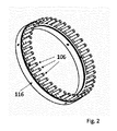
図1は、本発明による装置の移動装置の詳細を図示したものである。移動装置は、回転するドラム100の外側表面にある、間隙を介した複数のフルート102を有するドラム100を備える。フルート102は、ドラム100が回転する際に細長いロッドセグメント104を受けるように構成・配置される。ドラム100は、細長いフィルターロッドセグメント104がフルート102内に受けられた時に位置付けられる、それぞれのフルート102の一方の端で停止手段106をさらに備える。
FIG. 1 illustrates the details of the moving device of the device according to the present invention. The moving device comprises a
図3にもより詳しく図示する通り、停止手段106は、約8mmの第一の直径D1を有し、ドラム100上に取り付けられたドラムフレーム116(図2を参照)にピンが取り付けられる第一の端112と、第一の端112と反対側の第二の端114との間をフルートの軸(F)に沿って延びる、円筒形本体110を持つピン108を備える。さらに、ピン108は、円筒形本体110の第二の端114から軸(F)に沿って延びる隣接部分118を含む。隣接部分118は約6mmの第二の直径D2を持つ。隣接部分118は、細長いフィルターロッドセグメント104の端部に隣接するための実質的に平面の表面120を提示する。図1〜3に図示した実施形態において、隣接部分118は円筒形の形状を有し、約1mmの軸(F)に沿って測定される長さLを持つ。
As illustrated in more detail in FIG. 3, the stopping means 106 has a first diameter D1 of about 8 mm and a pin is attached to a drum frame 116 (see FIG. 2) mounted on the
図4は、本発明による装置の好ましい実施形態の動作ステーションのガニチュール200および加熱バー202の概略的断面図を示す。ガニチュール200は、作動可能なようにエンドレスベルトコンベヤー204と結合される。さらに、ガニチュール200は、フィルタープラグ材料および包装用ウェブ材料を受けるように構成され、かつ包装用ウェブ材料の第一および第二の長軸方向の端部が重なって、包装されたフィルターロッドを形成するように、包装用ウェブ材料をフィルタープラグ材料の周りで包装するように構成される。ガニチュール200はさらに、作動可能なように加熱バー202と結合され、これは、上流の位置で包装用ウェブ材料の長軸方向の側方端の一方または両方に塗布した接着剤を活性化するための熱を供給する。同時に、加熱バーは、ガニチュール200内を摺動自在に進むエンドレスベルト204の長軸方向の側方端を支持する。加熱バー202は、熱封着されている包装されたフィルターロッドを少なくとも部分的に受けるための円弧状の輪郭を持つ溝206を備える。図4に図示した通り、加熱バー202は一対の加熱バー陵208、210を備え、それぞれの加熱バー陵208、210は、一方の側で加熱バー溝206の境界を定め、また他方の側で支持表面212、214を提示する。加熱バー陵208、210の支持表面212、214は、ベルトがガニチュール200に沿って摺動自在に進む際に、ベルトの長軸方向の側方端をV字型配列で支持するように適合される。ベルト204の上側表面と加熱バー溝206の溝の表面によって画定される容積は、封着されている包装されたフィルターロッドを実質的に囲む。使用時、このことは、有利なことにベルト204が正確な中心位置から移動して離れるのを妨げ、かつ低楕円率の包装されたフィルターロッドの形成に有利に働く。図4の実施形態において、ホッパー陵208、210は、実質的に三角形の断面を有し、また支持表面212、214は、ベルトの長軸方向の側方端がそれらの間で約60度の角度αを形成するように傾いている。
FIG. 4 shows a schematic cross-sectional view of a
本発明による装置の動作ステーションは、フィルタープラグ材料の周りで封着するために包装用ウェブ材料の長軸方向の側方端に供給された接着剤を冷却し硬化させるために、ガニチュールおよびエンドレスベルトコンベヤーと動作可能なようにかつ熱的に結合された冷却バーをさらに備えることが好ましい。冷却バーは加熱バーのすぐ下流に配置される。こうした冷却バー300の詳細を図5に図示する。冷却バー300は、冷却バー入口304と冷却バー出口306の間に延びる長軸方向の溝302を備える。冷却バー溝302は、包装されたフィルターロッドを少なくとも部分的に受けるように適合される。使用時、冷却バー300は、ガニチュールの溝内を進むベルトの上側表面に面して長軸方向の溝302とともに配置され、ベルトの通路がガニチュールと冷却バーの間に画定されるように、ガニチュール(図示せず)から少し離して配置される。冷却バー入口304では、冷却バー溝302の断面は実質的に半円形である。冷却バー溝302は、冷却バー300とガニチュールの間を進むベルトの長軸方向の側方端と連携するように適合されたそれぞれの外側隣接表面を提示する側方の陵306、308によって横方向に境界が定められる。溝302の断面の表面積は、冷却バー入口304と冷却バー出口306の間で減少する。こうして、ベルトがガニチュールに沿って進む際、ベルトの長軸方向の側方端の向かい合った表面間の距離は、ベルトが冷却バー入口304に達する際に増大し、またベルトの長軸方向の側方端は冷却バー300の側方の陵306、308と接触するようになる。従って、ベルトは有利なことに、冷却バー入口304の下流の冷却バー300の残りの部分に対して摺動しないように抑制されるか、または少なくともベルトと冷却バー300の間の連携が著しく制限される。このことは、冷却バー300がベルトと冷却バー300の間の摩擦によって著しく加熱されないという点で有利である。同時に、包装されたフィルターロッドは、加熱バーによって活性化された接着剤が冷却バーと熱的に結合されるようになり、接着剤の急速な硬化が達成されうるように、ベルトと冷却バー溝の表面との間を進む。
The operating station of the device according to the invention is a ganiture and endless belt to cool and cure the adhesive supplied to the longitudinal lateral ends of the packaging web material for sealing around the filter plug material. It is preferred to further include a cooling bar that is operable and thermally coupled to the conveyor. The cooling bar is located just downstream of the heating bar. Details of such a
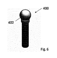
本発明による装置の好ましい一つの実施形態で使用するための圧縮手段400を図6に図示する。圧縮手段400は、作動可能なようにガニチュールと結合され、ガニチュールの下流端に配置され、また包装用ウェブ材料の重なり合った第一および第二の長軸方向の端部に沿った位置で、包装されたフィルターロッドと連携するように適合されている。より詳細には、圧縮手段400は、包装されたフィルターロッドの半径方向に実質的に沿って方向付けられた圧縮荷重をかけるように構成・配置される。図5の実施形態において、圧縮手段400は、実質的に球体の形状を持つ連携部分402を備える。
FIG. 6 illustrates the compression means 400 for use in one preferred embodiment of the apparatus according to the invention. The compression means 400 is operably coupled to the ganiture, located at the downstream end of the ganiture, and is packaged along the overlapping first and second longitudinal ends of the packaging web material. It is adapted to work with the filtered filter rod. More specifically, the compression means 400 is configured and arranged to apply a compressive load oriented substantially along the radial direction of the packaged filter rod. In the embodiment of FIG. 5, the compression means 400 includes a linking
圧縮手段は有利なことに、堅いまたは厚めの包装用ウェブ材料が、新しく形成された包装されたフィルターロッド内でフィルタープラグ材料の周りの完全に円筒形の配置から離れるように移動するという固有の傾向に効果的に対抗し、この固有の傾向は楕円形の主な原因の一つであると理解されている。さらに、球体の形状であるため、圧縮手段400は、圧縮手段400と包装されたフィルターロッドの外側表面との間の滑らかな連携を提供する。従って、包装されたフィルターロッドの表面仕上げは実質的に影響を受けず、またそのため、包装されたフィルターロッドの全体的な視覚的影響は有利なことに改善される。 The compression means is advantageous in that the rigid or thick packaging web material moves away from the completely cylindrical arrangement around the filter plug material within the newly formed packaged filter rod. Effectively countering trends, this unique tendency is understood to be one of the main causes of ellipses. Further, due to the spherical shape, the compression means 400 provides a smooth coordination between the compression means 400 and the outer surface of the packaged filter rod. Therefore, the surface finish of the packaged filter rod is substantially unaffected, and thus the overall visual effect of the packaged filter rod is advantageously improved.
Claims (12)
フィルタープラグ材料および包装用ウェブ材料を受けるための、ならびに前記フィルタープラグ材料および前記包装用ウェブ材料から、包装されたフィルターロッドを形成するための動作ステーションと、
前記包装されたフィルターロッドを細長いロッドセグメントに切断するための少なくとも一つのカッターブレードと、
間隙を介した複数の溝部を外側表面上に有する回転ドラムを含んでいる移動装置と、を備え、前記溝部は、前記ドラムの回転に際して前記細長いロッドセグメントを受けるように構成・配置され、前記ドラムは、前記細長いロッドセグメントが前記溝部内に受けられた時に、前記細長いロッドセグメントが位置付けられる、それぞれの前記溝部の一方の端に停止手段をさらに備えており、
前記停止手段が、円筒形本体を持つピンを備え、該円筒形本体は、第一の直径(D1)を有し、且つ、前記ピンがドラムフレームに取り付けられる第一の端と前記第一の端と反対側の第二の端との間を溝部の軸(F)に沿って延びており、
前記ピンが、前記円筒形本体の前記第二の端から前記軸(F)に沿って延びる隣接部分を含み、前記隣接部分が、前記第一の直径(D1)よりも小さい第二の直径(D2)を有し、かつ前記細長いロッドセグメントの端部に隣接するための実質的に平面の表面を提示する、装置。 A device for producing a filter rod for use in the manufacture of smoking articles, wherein the device is
An operating station for receiving the filter plug material and the packaging web material, and for forming a packaged filter rod from the filter plug material and the packaging web material.
With at least one cutter blade for cutting the packaged filter rod into elongated rod segments,
A moving device including a rotating drum having a plurality of grooves on the outer surface via a gap is provided, and the groove is configured and arranged so as to receive the elongated rod segment when the drum rotates. , when the elongate rod segments have been received in said groove, said elongate rod segments is positioned further comprises a stop means at one end of each of said grooves,
The stopping means comprises a pin having a cylindrical body, the cylindrical body having a first diameter (D1), and a first end to which the pin is attached to a drum frame and the first. It extends between the end and the second end on the opposite side along the axis (F) of the groove.
The pin comprises an adjacent portion extending along the axis (F) from the second end of the cylindrical body, the adjacent portion having a second diameter (D1) smaller than the first diameter (D1). A device having D2) and presenting a substantially flat surface for adjoining the end of the elongated rod segment.
作動可能なようにエンドレスベルトコンベヤーと結合され、また前記フィルタープラグ材料および前記包装用ウェブ材料を受けるように、かつ前記包装用ウェブ材料の第一および第二の長軸方向の端部が重なって前記包装されたフィルターロッドを形成するように、前記包装用ウェブ材料をフィルタープラグ材料の周りで包装するように構成された、ガーニチャーと、
前記包装用ウェブ材料の前記重なり合った第一および前記第二の長軸方向の端部を封着するための接着剤を供給するためのアプリケータとを備える、装置。 The apparatus according to any one of claims 1 to 5, wherein the operating station is a device.
Combined with an endless conveyor belt to operate, and to receive the filter plug material and the packaging web material, and the first and second longitudinal ends of the packaging web material overlap. With a garniture configured to wrap the packaging web material around the filter plug material so as to form the packaged filter rod.
An apparatus comprising an applicator for supplying an adhesive for sealing the overlapping first and second longitudinal ends of the packaging web material.
Applications Claiming Priority (3)
| Application Number | Priority Date | Filing Date | Title |
|---|---|---|---|
| EP15179400 | 2015-07-31 | ||
| EP15179400.5 | 2015-07-31 | ||
| PCT/EP2016/068278 WO2017021347A1 (en) | 2015-07-31 | 2016-08-01 | Improved filter rod maker for handling stiff wrapping web material |
Publications (3)
| Publication Number | Publication Date |
|---|---|
| JP2018521660A JP2018521660A (en) | 2018-08-09 |
| JP2018521660A5 JP2018521660A5 (en) | 2021-01-28 |
| JP6976927B2 true JP6976927B2 (en) | 2021-12-08 |
Family
ID=53773328
Family Applications (1)
| Application Number | Title | Priority Date | Filing Date |
|---|---|---|---|
| JP2018503150A Active JP6976927B2 (en) | 2015-07-31 | 2016-08-01 | Improved filter rod manufacturer for handling rigid packaging web materials |
Country Status (8)
| Country | Link |
|---|---|
| EP (1) | EP3328221B1 (en) |
| JP (1) | JP6976927B2 (en) |
| KR (1) | KR20180034345A (en) |
| CN (1) | CN107734980B (en) |
| BR (1) | BR112017028513B1 (en) |
| PL (1) | PL3328221T3 (en) |
| RU (1) | RU2703105C2 (en) |
| WO (1) | WO2017021347A1 (en) |
Families Citing this family (2)
| Publication number | Priority date | Publication date | Assignee | Title |
|---|---|---|---|---|
| DE102018104956A1 (en) * | 2018-03-05 | 2019-09-05 | Hauni Maschinenbau Gmbh | Conveyor drum of the tobacco processing industry |
| KR20220076504A (en) * | 2019-10-09 | 2022-06-08 | 필립모리스 프로덕츠 에스.에이. | Method and apparatus for forming continuous web material into rods |
Family Cites Families (14)
| Publication number | Priority date | Publication date | Assignee | Title |
|---|---|---|---|---|
| IT1142328B (en) * | 1981-02-23 | 1986-10-08 | Gd Spa | CIGARETTE PACKAGING MACHINE WITH LEVEL CONTROL IN THE CHIMNEY TOBACCO FEEDING CHIMNEY |
| US4768526A (en) * | 1983-06-02 | 1988-09-06 | R. J. Reynolds Tobacco Company | Tobacco smoke filters |
| JPH01132367A (en) * | 1987-11-18 | 1989-05-24 | Japan Tobacco Inc | Apparatus for manufacturing cigarette filter |
| JP3437634B2 (en) * | 1994-03-31 | 2003-08-18 | 日本たばこ産業株式会社 | Coaxial moving alignment device for filter plug supply device |
| GB9809720D0 (en) * | 1998-05-06 | 1998-07-08 | Molins Plc | Cigarette making machine |
| DE19858600A1 (en) * | 1998-12-18 | 2000-06-21 | Hauni Maschinenbau Ag | Device for the longitudinal axial positioning of rod-shaped articles to be cut in the tobacco processing industry |
| WO2004089120A1 (en) * | 2003-04-07 | 2004-10-21 | Japan Tobacco Inc. | Machine and method for manufacturing cigarette |
| US7115085B2 (en) * | 2003-09-12 | 2006-10-03 | R.J. Reynolds Tobacco Company | Method and apparatus for incorporating objects into cigarette filters |
| JP2009112276A (en) * | 2007-11-08 | 2009-05-28 | Japan Filter Technology Ltd | Rod-forming machine |
| IT1392375B1 (en) * | 2008-07-18 | 2012-03-02 | Gd Spa | PACKAGING MACHINE FOR THE PRODUCTION OF COMBINED FILTERS FOR CIGARETTES. |
| DE102011006025B3 (en) * | 2011-03-24 | 2012-07-19 | Hauni Maschinenbau Ag | Production of filter stoppers or filter cigarettes |
| PL219777B1 (en) * | 2012-03-26 | 2015-07-31 | Int Tobacco Machinery Poland | A cleaning system for a drum transporter device, filter segments for administration to a device producing multi-segment filters and a method for cleaning the drum transporter device |
| DE102012018370A1 (en) * | 2012-09-18 | 2014-03-20 | Hauni Maschinenbau Ag | Rotary conveying device for conveying articles of the tobacco processing industry |
| DE102013210634A1 (en) * | 2013-06-07 | 2014-12-11 | Hauni Maschinenbau Ag | Sliding drum for a machine of the tobacco processing industry |
-
2016
- 2016-08-01 WO PCT/EP2016/068278 patent/WO2017021347A1/en active Application Filing
- 2016-08-01 BR BR112017028513-4A patent/BR112017028513B1/en active IP Right Grant
- 2016-08-01 PL PL16745738T patent/PL3328221T3/en unknown
- 2016-08-01 CN CN201680040136.2A patent/CN107734980B/en active Active
- 2016-08-01 JP JP2018503150A patent/JP6976927B2/en active Active
- 2016-08-01 KR KR1020177037918A patent/KR20180034345A/en not_active Application Discontinuation
- 2016-08-01 EP EP16745738.1A patent/EP3328221B1/en active Active
- 2016-08-01 RU RU2017146616A patent/RU2703105C2/en active
Also Published As
| Publication number | Publication date |
|---|---|
| EP3328221B1 (en) | 2019-10-02 |
| RU2017146616A (en) | 2019-08-28 |
| BR112017028513A2 (en) | 2018-08-28 |
| EP3328221A1 (en) | 2018-06-06 |
| BR112017028513B1 (en) | 2021-06-29 |
| CN107734980B (en) | 2020-12-11 |
| WO2017021347A1 (en) | 2017-02-09 |
| PL3328221T3 (en) | 2020-05-18 |
| RU2017146616A3 (en) | 2019-08-28 |
| RU2703105C2 (en) | 2019-10-15 |
| KR20180034345A (en) | 2018-04-04 |
| JP2018521660A (en) | 2018-08-09 |
| CN107734980A (en) | 2018-02-23 |
Similar Documents
| Publication | Publication Date | Title |
|---|---|---|
| US11076635B2 (en) | Method, mechanism and apparatus for momentary compression of filter material | |
| EP3254570B1 (en) | Filter cigarette producing method, filter and filter cigarette | |
| US20150114988A1 (en) | Fluid feeding method and nozzle | |
| JP6364540B2 (en) | Method for producing cigarette with filter | |
| US20150114543A1 (en) | Fluid feeding method and nozzle | |
| JP6976927B2 (en) | Improved filter rod manufacturer for handling rigid packaging web materials | |
| ITBO20110419A1 (en) | DEVICE AND METHOD OF ROLLING OF CIGARETTES WITH FILTER. | |
| CA1093417A (en) | Production of rod-shape elements | |
| ITBO20110331A1 (en) | METHOD AND FILTER MACHINE TO MAKE CIGARETTES WITH FILTER. | |
| EP1917871B1 (en) | A machine manufacturing filters for tobacco products | |
| JPS6234387B2 (en) | ||
| EP3007570B1 (en) | Method and shoe for pressing segments of multi-segment filter | |
| KR20190111792A (en) | Apparatus and method for producing a strand from web material | |
| JP2018521660A5 (en) | ||
| WO2017001348A1 (en) | Filter rod maker with air dust removal | |
| RU2747031C2 (en) | Method for reducing the voltage of the setting tape in the machine for the tobacco industry, the method for reducing the clearance in the machine for the tobacco industry and the setting device for the machine for the tobacco industry | |
| KR102601390B1 (en) | A feeding device for feeding continuous strips within a continuous fiber band in a tobacco industry machine for manufacturing rod-shaped elements and a machine for manufacturing rod-shaped elements | |
| IT202100025961A1 (en) | Machine for the production of sachets of loose material and related maintenance method | |
| PL241632B1 (en) | Formatting device, machine for manufacturing multi-segmented cigarette filter slabs and method for manufacturing multi-segmented cigarette filter slabs |
Legal Events
| Date | Code | Title | Description |
|---|---|---|---|
| A621 | Written request for application examination |
Free format text: JAPANESE INTERMEDIATE CODE: A621 Effective date: 20190723 |
|
| A977 | Report on retrieval |
Free format text: JAPANESE INTERMEDIATE CODE: A971007 Effective date: 20200911 |
|
| A131 | Notification of reasons for refusal |
Free format text: JAPANESE INTERMEDIATE CODE: A131 Effective date: 20200923 |
|
| A524 | Written submission of copy of amendment under section 19 (pct) |
Free format text: JAPANESE INTERMEDIATE CODE: A524 Effective date: 20201211 |
|
| A131 | Notification of reasons for refusal |
Free format text: JAPANESE INTERMEDIATE CODE: A131 Effective date: 20210513 |
|
| A521 | Written amendment |
Free format text: JAPANESE INTERMEDIATE CODE: A523 Effective date: 20210526 |
|
| TRDD | Decision of grant or rejection written | ||
| A01 | Written decision to grant a patent or to grant a registration (utility model) |
Free format text: JAPANESE INTERMEDIATE CODE: A01 Effective date: 20211011 |
|
| A61 | First payment of annual fees (during grant procedure) |
Free format text: JAPANESE INTERMEDIATE CODE: A61 Effective date: 20211110 |
|
| R150 | Certificate of patent or registration of utility model |
Ref document number: 6976927 Country of ref document: JP Free format text: JAPANESE INTERMEDIATE CODE: R150 |