JP6976099B2 - Stop position detection system - Google Patents

Stop position detection system Download PDF

Info

Publication number
JP6976099B2
JP6976099B2 JP2017148671A JP2017148671A JP6976099B2 JP 6976099 B2 JP6976099 B2 JP 6976099B2 JP 2017148671 A JP2017148671 A JP 2017148671A JP 2017148671 A JP2017148671 A JP 2017148671A JP 6976099 B2 JP6976099 B2 JP 6976099B2
Authority
JP
Japan
Prior art keywords
train
stop
fixed
sensor
absence
Prior art date
Legal status (The legal status is an assumption and is not a legal conclusion. Google has not performed a legal analysis and makes no representation as to the accuracy of the status listed.)
Active
Application number
JP2017148671A
Other languages
Japanese (ja)
Other versions
JP2019026127A (en
JP2019026127A5 (en
Inventor
和史 河野
Current Assignee (The listed assignees may be inaccurate. Google has not performed a legal analysis and makes no representation or warranty as to the accuracy of the list.)
Mitsubishi Electric Corp
Original Assignee
Mitsubishi Electric Corp
Priority date (The priority date is an assumption and is not a legal conclusion. Google has not performed a legal analysis and makes no representation as to the accuracy of the date listed.)
Filing date
Publication date
Application filed by Mitsubishi Electric Corp filed Critical Mitsubishi Electric Corp
Priority to JP2017148671A priority Critical patent/JP6976099B2/en
Publication of JP2019026127A publication Critical patent/JP2019026127A/en
Publication of JP2019026127A5 publication Critical patent/JP2019026127A5/ja
Application granted granted Critical
Publication of JP6976099B2 publication Critical patent/JP6976099B2/en
Active legal-status Critical Current
Anticipated expiration legal-status Critical

Links

Images

Description

本発明は、停止位置検知システムに関する。 The present invention relates to a stop position detection system.

鉄道駅のプラットホームへの可動式ホーム柵の設置が進んでいる。可動式ホーム柵が設置されると、列車は、その乗降扉と可動式ホーム柵によって開閉される乗降通路とが一致する定停止位置に停止する必要がある。 Movable platform fences are being installed on the platforms of railway stations. Once the movable platform screen doors are installed, the train must stop at a fixed stop position where the platform doors and the boarding / aisles opened and closed by the movable platform screen doors coincide.

列車が定停止位置に停止したか否かを判別するために、従来、自動列車運転装置、定位置停止装置などが使用されている。しかし、これらの装置は、大規模なシステムであり、大きなコストが必要となる。そこで、列車の停止位置を検出する簡易なシステムが求められている。 Conventionally, an automatic train operation device, a fixed-position stop device, or the like has been used to determine whether or not a train has stopped at a fixed stop position. However, these devices are large-scale systems and require a large cost. Therefore, there is a demand for a simple system for detecting the stop position of a train.

特許文献1には、超音波により列車までの距離を測定し、測定した距離の変動から、列車が停止したことを検知する技術が開示されている。 Patent Document 1 discloses a technique of measuring a distance to a train by ultrasonic waves and detecting that the train has stopped from the fluctuation of the measured distance.

特許文献2には、マイクロ波を用いて列車までの距離を測定し、測定した距離から、列車の停止状態および停止位置を検出する技術が開示されている。 Patent Document 2 discloses a technique of measuring a distance to a train using microwaves and detecting a stopped state and a stopped position of the train from the measured distance.

特開2002−284010号公報Japanese Unexamined Patent Publication No. 2002-284010 特開2014−061796号公報Japanese Unexamined Patent Publication No. 2014-061796

特許文献1に記載の技術は、先行する列車と後続の列車とを併結させるために先行する列車の停止などの状態を判定することを前提とする。そのため、特許文献1に記載の技術を、列車を定停止位置に停止させる場合には適応できない。 The technique described in Patent Document 1 is premised on determining a state such as a stop of a preceding train in order to combine a preceding train and a succeeding train. Therefore, the technique described in Patent Document 1 cannot be applied when the train is stopped at a fixed stop position.

また、特許文献2に記載の技術は、マイクロ波は、ホーム上の反射物による外乱及び風、雨、雪などの環境による外乱の影響を受け、計測された距離に誤差が生じる。このため、特許文献2に記載された停止位置検出装置は、定位置停止判定の信頼性が低い。 Further, in the technique described in Patent Document 2, microwaves are affected by disturbances due to reflectors on the platform and disturbances due to the environment such as wind, rain, and snow, and an error occurs in the measured distance. Therefore, the stop position detection device described in Patent Document 2 has low reliability of fixed-position stop determination.

本発明は、このような背景の下でなされたものであり、簡易な構成で、信頼性の高い定位置停止判定を行う停止位置検知システムを提供することを目的とする。 The present invention has been made under such a background, and an object of the present invention is to provide a stop position detection system that performs a highly reliable fixed-position stop determination with a simple configuration.

上述の目的を達成するために、本発明に係る停止位置検知システムは、軌道上の列車の定停止位置よりも進行方向前方又は後方に設置され、列車の位置と列車の状態とを検出する定位置停止判別手段と、定停止位置において、列車の在否を検知する在否検知手段と、定位置停止判別手段で検出された列車の位置が予め設定された範囲にあり且つ列車が停止状態にあり、かつ、在否検知手段が列車の存在を検知している場合に、列車が存在していることを示す情報を外部機器に出力する判別手段と、を備える。列車には車両情報を保持する媒体が配置されており、在否検知手段は、媒体から車両情報を取得する在否検知センサを備え、判別手段は、取得した車両情報の示す列車が、入線予定の列車と一致するか否かを判定し、一致する場合に、列車が存在していると判定する。さらに、外部機器は、軌道に隣接するプラットホームに設置された可動式ホーム柵であり、可動式ホーム柵は、開閉自在の扉体と、扉体が収納される戸袋と、扉体を制御する制御部とを備え、在否検知手段は、可動式ホーム柵の戸袋に取り付けられて、車両の在否を判定するための情報を収拾するセンサを備え、可動式ホーム柵の制御部は、判別手段から出力された判定結果に基づいて、当該可動式ホーム柵の扉体を制御する。 In order to achieve the above object, the stop position detection system according to the present invention is installed in front of or behind the fixed stop position of the train on the track in the traveling direction, and detects the position of the train and the state of the train. The position stop determination means, the presence / absence detection means for detecting the presence / absence of the train at the fixed stop position, and the position of the train detected by the fixed position stop determination means are within a preset range and the train is in a stopped state. It also includes a discriminating means for outputting information indicating the existence of a train to an external device when the presence / absence detecting means detects the existence of the train. A medium for holding vehicle information is arranged on the train, the presence / absence detection means is equipped with a presence / absence detection sensor that acquires vehicle information from the medium, and the determination means is that the train indicated by the acquired vehicle information is scheduled to enter the line. It is determined whether or not the train matches the train, and if it matches, it is determined that the train exists. Further, the external device is a movable platform fence installed on a platform adjacent to the track, and the movable platform fence is a door body that can be opened and closed, a door pocket in which the door body is stored, and a control that controls the door body. The presence / absence detection means is attached to the door pocket of the movable platform screen door and includes a sensor for collecting information for determining the presence / absence of the vehicle, and the control unit of the movable platform fence is a determination means. The door body of the movable platform fence is controlled based on the determination result output from.

本発明によれば、列車の位置と列車の状態とを検出する定位置停止判別手段と、軌道上の列車の在否を検知する在否検知手段の両方を用いて、列車が定停止位置に停止していることを判定するため、定位置停止判別手段だけで列車が定停止位置に停止していること判定する場合に比べて、信頼性の高い定位置停止判定を行うことができる。 According to the present invention, a train is set to a fixed stop position by using both a fixed-position stop determining means for detecting the position of the train and the state of the train and the presence / absence detecting means for detecting the presence / absence of the train on the track. Since it is determined that the train is stopped, it is possible to perform a highly reliable fixed-position stop determination as compared with the case where it is determined that the train is stopped at the fixed-position stop position only by the fixed-position stop determination means.

本発明の実施の形態1に係る停止位置検知システムの全体構成を概略的に示す構成図A block diagram schematically showing the overall configuration of the stop position detection system according to the first embodiment of the present invention. 実施の形態1に係る停止位置検知システムのブロック図Block diagram of the stop position detection system according to the first embodiment 実施の形態1に係る定位置停止センサによる距離計測の概要を示した概要図であり、(A)は平面図、(B)は説明図It is a schematic diagram which showed the outline of the distance measurement by the fixed-position stop sensor which concerns on Embodiment 1, (A) is a plan view, (B) is an explanatory view. 実施の形態1に係る停止位置判定プログラムによる処理を示したフローチャートA flowchart showing processing by the stop position determination program according to the first embodiment. 実施の形態1に係る定位置停止センサ出力取得関数による処理を示したフローチャートA flowchart showing processing by the fixed-position stop sensor output acquisition function according to the first embodiment. 本発明の実施の形態2に係る停止位置検知システムの構成を概略的に示す構成図であり、(A)は外形図、(B)は平面図It is a block diagram which shows schematic structure of the stop position detection system which concerns on Embodiment 2 of this invention, (A) is an outline view, (B) is a plan view. 実施の形態2に係る停止位置判定プログラムの処理を示したフローチャートA flowchart showing the processing of the stop position determination program according to the second embodiment. 本発明の実施の形態3に係る停止位置検知システムの外形図Outline of the stop position detection system according to the third embodiment of the present invention. 実施の形態3に係る列車在否検知の概要を示した概要図Schematic diagram showing the outline of train presence / absence detection according to the third embodiment 実施の形態3に係る停止位置判定プログラムの処理を示したフローチャートA flowchart showing the processing of the stop position determination program according to the third embodiment. 本発明の実施の形態4に係る停止位置判定プログラムによる処理を示したフローチャートA flowchart showing processing by the stop position determination program according to the fourth embodiment of the present invention.

以下、本発明の実施形態に係る停止位置検知システムについて、図面を参照しつつ説明する。なお、同一または同等の部分に同一の符号を付す。 Hereinafter, the stop position detection system according to the embodiment of the present invention will be described with reference to the drawings. The same or equivalent parts are designated by the same reference numerals.

(実施の形態1)
実施の形態1に係る停止位置検知システムについて、図1から図5を参照して説明する。
(Embodiment 1)
The stop position detection system according to the first embodiment will be described with reference to FIGS. 1 to 5.

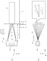
なお、以下の説明において、理解を容易にするため、図1に示すようにプラットホーム2の長手方向にX座標を、高さ方向にY座標を、X座標とY座標に直交する方向、つまりプラットホーム2の幅方向にZ座標を、設定し、適宜参照する。また、図1において左から右に向かう方向を+X方向、下から上に向かう方向を+Y方向、軌道からプラットホーム2に向かう方向を+Z方向とする。 In the following description, in order to facilitate understanding, as shown in FIG. 1, the X coordinate is in the longitudinal direction of the platform 2, the Y coordinate is in the height direction, and the direction orthogonal to the X coordinate and the Y coordinate, that is, the platform. Set the Z coordinate in the width direction of 2 and refer to it as appropriate. Further, in FIG. 1, the direction from left to right is the + X direction, the direction from the bottom to the top is the + Y direction, and the direction from the orbit to the platform 2 is the + Z direction.

まず、前提として、本実施の形態の停止位置検知システムと共に使用される可動式ホーム柵1について説明する。
図1に示すように、可動式ホーム柵1は、プラットホーム2に固定された固定部4と、固定部4に取り付けられて、乗降通路5を開閉する扉体6a,6bとを備える。
First, as a premise, the movable platform fence 1 used together with the stop position detection system of the present embodiment will be described.
As shown in FIG. 1, the movable platform fence 1 includes a fixing portion 4 fixed to the platform 2 and door bodies 6a and 6b attached to the fixing portion 4 to open and close the boarding / alighting passage 5.

固定部4は、箱形に形成されており、一般には戸袋と呼ばれる。固定部4は、プラットホーム2の床面にX軸方向に複数台並んで設置されている。各固定部4には、扉体6a,6bがX軸方向に進退自在に収容され、また、扉体6a,6bを駆動する駆動機構と駆動機構を制御する制御部が配置されている。なお、両端の固定部4には、扉体6aと6bの一方のみが収容されている。 The fixing portion 4 is formed in a box shape and is generally called a door pocket. A plurality of fixing portions 4 are installed side by side on the floor surface of the platform 2 in the X-axis direction. The door bodies 6a and 6b are housed in the fixed portions 4 so as to be able to move forward and backward in the X-axis direction, and a drive mechanism for driving the door bodies 6a and 6b and a control unit for controlling the drive mechanism are arranged. Only one of the door bodies 6a and 6b is housed in the fixing portions 4 at both ends.

扉体6a,6bは、乗降通路5を開閉する開閉部材として機能し、固定部4に進退自在に取り付けられたスライドドアである。図1は、扉体6a,6bが固定部4の外に引き出されて、戸先が互いに当接し、乗降通路5を閉鎖した状態を示している。なお、乗降通路5が開放されている状態では、扉体6a,6bは固定部4の中に引き込まれている。 The door bodies 6a and 6b function as opening / closing members for opening and closing the boarding / alighting passage 5, and are slide doors that are freely attached to the fixing portion 4 in an advancing / retreating manner. FIG. 1 shows a state in which the door bodies 6a and 6b are pulled out of the fixed portion 4, the door ends are in contact with each other, and the boarding / alighting passage 5 is closed. In the state where the boarding / alighting passage 5 is open, the door bodies 6a and 6b are pulled into the fixed portion 4.

各軌道には、列車の種別毎に、列車20の先頭部の停止目標位置P0が予め定められている。 In each track, the stop target position P0 at the head of the train 20 is predetermined for each type of train.

停止目標位置P0に隣接した固定部4には、データ処理装置7が取り付けられている。データ処理装置7の詳細は後述する。 A data processing device 7 is attached to the fixed portion 4 adjacent to the stop target position P0. Details of the data processing device 7 will be described later.

データ処理装置7が取り付けられた固定部4の+X方向に隣接した固定部4にはRFID(Radio Frequency IDentifier)リーダ8が取り付けられている。RFIDリーダ8には、RFIDタグ23を検出するアンテナ9が接続されている。RFIDタグ23には、システムID、そのRFIDタグ23が取り付けられている列車の車種、列車識別情報などの車両情報が事前に書き込まれている。RFIDタグ23は、列車20の先頭車両のプラットホーム2の下に隠れる部分に予め取り付けられている。アンテナ9は、列車20に取り付けられたRFIDタグ23と同じ高さになるように、プラットホーム2の下に配置されている。RFIDタグ23とアンテナ9との高さをそろえることにより、列車20がアンテナ9の前を通過又は停止した際に、アンテナ9がRFIDタグ23を容易に検出することができる。 An RFID (Radio Frequency IDentifier) reader 8 is attached to the fixed portion 4 adjacent to the fixed portion 4 to which the data processing device 7 is attached in the + X direction. An antenna 9 for detecting the RFID tag 23 is connected to the RFID reader 8. Vehicle information such as a system ID, a vehicle type of the train to which the RFID tag 23 is attached, and train identification information is written in advance on the RFID tag 23. The RFID tag 23 is pre-attached to a portion hidden under the platform 2 of the leading car of the train 20. The antenna 9 is arranged under the platform 2 so as to be at the same height as the RFID tag 23 attached to the train 20. By aligning the heights of the RFID tag 23 and the antenna 9, the antenna 9 can easily detect the RFID tag 23 when the train 20 passes or stops in front of the antenna 9.

次に、実施の形態1に係る停止位置検知システム100について説明する。 Next, the stop position detection system 100 according to the first embodiment will be described.

停止位置検知システム100は、図2に示すように、列車20の停止位置が定停止位置であるか否かを判別するための定位置停止センサ50と、軌道上に列車20が存在するか否かを検知する在否検知センサ51と、定位置停止センサ50の出力信号と在否検知センサ51の出力信号を処理し、列車20が定停止位置に停止しているか否かの判定を行うデータ処理装置7と、を備えている。 As shown in FIG. 2, the stop position detection system 100 includes a fixed-position stop sensor 50 for determining whether or not the stop position of the train 20 is a fixed stop position, and whether or not the train 20 is on the track. Data that processes the presence / absence detection sensor 51 that detects the presence / absence, the output signal of the fixed-position stop sensor 50, and the output signal of the presence / absence detection sensor 51, and determines whether or not the train 20 is stopped at the fixed-stop position. It is provided with a processing device 7.

定位置停止センサ50は、図1に示すように、列車20の進行方向の線路脇に配置されており、列車20が定位置に停車しているか否かと、列車20が停止状態であるか否かを検出するためのセンサである。本実施の形態では、定位置停止センサ50は、図2に示すように、列車20の先頭部までの距離値Lを示す信号を出力する。すなわち、定位置停止センサ50は一種の距離センサである。 As shown in FIG. 1, the fixed-position stop sensor 50 is arranged on the side of the track in the traveling direction of the train 20, and whether or not the train 20 is stopped at a fixed position and whether or not the train 20 is stopped. It is a sensor for detecting. In the present embodiment, the fixed-position stop sensor 50 outputs a signal indicating a distance value L to the head portion of the train 20, as shown in FIG. That is, the fixed-position stop sensor 50 is a kind of distance sensor.

図2に示す在否検知センサ51は、プラットホーム2に接した軌道上に列車20が存在するか否かを判別し、在否検知信号を出力する。在否検知センサ51は、本実施の形態では、固定部4に設置されたRFIDリーダ8である。RFIDリーダ8は、アンテナ9から送信される近距離の電波により、列車20に取り付けられたRFIDタグ23と無線通信を行い、RFIDタグ23から車両情報を読み出す。また、在否検知信号は、RFIDリーダ8が列車20に取り付けられたRFIDタグ23から読み出した車両情報のうち、車種データが示す車種が相当する。 The presence / absence detection sensor 51 shown in FIG. 2 determines whether or not the train 20 is on the track in contact with the platform 2, and outputs a presence / absence detection signal. In the present embodiment, the presence / absence detection sensor 51 is an RFID reader 8 installed in the fixed portion 4. The RFID reader 8 wirelessly communicates with the RFID tag 23 attached to the train 20 by a short-distance radio wave transmitted from the antenna 9, and reads vehicle information from the RFID tag 23. Further, the presence / absence detection signal corresponds to the vehicle type indicated by the vehicle type data among the vehicle information read from the RFID tag 23 attached to the train 20 by the RFID reader 8.

データ処理装置7は、コンピュータであり、固定部4に配置され、定位置停止センサ50から送信された信号と在否検知センサ51から送信された信号とに基づいて、列車20が定停止位置に停止しているか否かを判定する。判定手法については、図5及び図6を参照して後述する。 The data processing device 7 is a computer, which is arranged in the fixed unit 4, and the train 20 is set to the fixed stop position based on the signal transmitted from the fixed position stop sensor 50 and the signal transmitted from the presence / absence detection sensor 51. Determine if it is stopped. The determination method will be described later with reference to FIGS. 5 and 6.

データ処理装置7は、列車20が定停止位置に停止していると判定すると、外部機器60に停止確認信号を出力する。外部機器60は、例えば、可動式ホーム柵1の制御部や、列車20の乗務員に列車20の状態を報知する報知装置などである。例えば、可動式ホーム柵1の制御部は、データ処理装置7からの停止確認信号に応答して、駆動機構を駆動し扉体6a,6bを開き、乗降通路5を開く。また、報知装置は、列車20の乗務員に、列車20が定停止位置に停車したことを報知する。乗務員は、例えば、この報知を確認した上で、列車20の乗降扉を開く。 When the data processing device 7 determines that the train 20 has stopped at the fixed stop position, it outputs a stop confirmation signal to the external device 60. The external device 60 is, for example, a control unit of the movable platform fence 1 or a notification device for notifying the crew of the train 20 of the state of the train 20. For example, the control unit of the movable platform fence 1 drives the drive mechanism to open the door bodies 6a and 6b in response to the stop confirmation signal from the data processing device 7, and opens the boarding / alighting passage 5. Further, the notification device notifies the crew of the train 20 that the train 20 has stopped at a fixed stop position. The crew, for example, opens the boarding / alighting door of the train 20 after confirming this notification.

定位置停止センサ50は、列車20の先頭部に赤外線レーザなどのレーザ光30を照射し、その反射光を受光する第1距離センサ501および第2距離センサ502と、第1距離センサ501および第2距離センサ502を制御する制御部503を具備する。第1距離センサ501は主系の距離センサであり、第2距離センサ502は従系の距離センサである。 The fixed position stop sensor 50 irradiates the head portion of the train 20 with a laser beam 30 such as an infrared laser, and receives the reflected light of the first distance sensor 501 and the second distance sensor 502, and the first distance sensor 501 and the first distance sensor 50. A control unit 503 that controls the two-distance sensor 502 is provided. The first distance sensor 501 is the main distance sensor, and the second distance sensor 502 is the slave distance sensor.

図3(A)に平面図で示すように、第1距離センサ501と第2距離センサ502は、列車20の先頭部の正面に対して左右の位置にそれぞれ配置されている。第1距離センサ501と第2距離センサ502は、それぞれ、列車20の先頭部までの距離値Lを計測する。制御部503は、第1距離センサ501と第2距離センサ502によりそれぞれ測定された距離値Lの平均を求め、求めた距離を距離値Lとする。このように、センサ機能を二重化することで、距離の計測の精度を高めることができる。 As shown in the plan view of FIG. 3A, the first distance sensor 501 and the second distance sensor 502 are arranged at left and right positions with respect to the front of the front portion of the train 20. The first distance sensor 501 and the second distance sensor 502 each measure the distance value L to the head portion of the train 20. The control unit 503 obtains the average of the distance values L measured by the first distance sensor 501 and the second distance sensor 502, respectively, and sets the obtained distance as the distance value L. By duplicating the sensor function in this way, the accuracy of distance measurement can be improved.

図3(B)に側面で示すように、第1距離センサ501と第2距離センサ502は、それぞれ、列車20の先頭部に向けて、半円状のフィールドを周期的に上下方向にスキャンする。例えば、スキャン周期は25msec、走査角度は190°、角度分解能は0.25°、1スキャン毎の計測点数は760ポイント、計測距離は最大100mである。 As shown on the side surface in FIG. 3B, the first distance sensor 501 and the second distance sensor 502 periodically scan the semicircular field in the vertical direction toward the head portion of the train 20, respectively. .. For example, the scan cycle is 25 msec, the scan angle is 190 °, the angular resolution is 0.25 °, the number of measurement points per scan is 760 points, and the maximum measurement distance is 100 m.

制御部503は、1スキャン毎に、水平に対する各走査角度θにおいて、列車20の先頭部までの距離値であるセンサ検出距離値aを算出する。制御部503は、1ポイントごとに走査角度θとセンサ検出距離値aとを基に、列車20の先頭部までの水平距離値bを、b=a×Cosθから算出する。制御部503は、1スキャンで得られたNポイントの水平距離値bの中央値Mを中心に、特定の±Xmm以上の差がある値、即ち、(M+X)以上の値と(M−X)以下の値を無効値として除外し、残りの値を有効値とする。制御部503は、有効値のみの平均値をとって、1スキャンで得られる有効水平距離値cとする。制御部503は、第1距離センサ501により求められた有効水平距離値cと第2距離センサ502により求められた有効水平距離値cとの平均値を、定位置停止センサ50と列車20の先頭部の間の距離値Lとする。 The control unit 503 calculates the sensor detection distance value a, which is the distance value to the head portion of the train 20, at each scanning angle θ with respect to the horizontal for each scan. The control unit 503 calculates the horizontal distance value b to the head portion of the train 20 from b = a × Cos θ based on the scanning angle θ and the sensor detection distance value a for each point. The control unit 503 has a value having a specific difference of ± X mm or more, that is, a value of (M + X) or more and (MX) centered on the median value M of the horizontal distance value b of the N points obtained in one scan. ) Exclude the following values as invalid values and use the remaining values as valid values. The control unit 503 takes the average value of only the effective values and uses it as the effective horizontal distance value c obtained in one scan. The control unit 503 sets the average value of the effective horizontal distance value c obtained by the first distance sensor 501 and the effective horizontal distance value c obtained by the second distance sensor 502 at the head of the fixed position stop sensor 50 and the train 20. Let L be the distance value between the parts.

制御部503は、第1距離センサ501と第2距離センサ502とが計測した距離値Lの平均値をデータ処理装置7に出力する。 The control unit 503 outputs the average value of the distance values L measured by the first distance sensor 501 and the second distance sensor 502 to the data processing device 7.

在否検知センサ51は、前述のように、RFIDリーダ8を備える。在否検知センサ51は、RFIDリーダ8が、列車20に設置されたRFIDタグ23から読み取った車両情報に含まれる車種を示す情報をデータ処理装置7に出力する。 As described above, the presence / absence detection sensor 51 includes the RFID reader 8. The presence / absence detection sensor 51 outputs to the data processing device 7 information indicating the vehicle type included in the vehicle information read from the RFID tag 23 installed on the train 20 by the RFID reader 8.

データ処理装置7は、列車20の先頭部が定停止位置範囲内に位置し、列車20が停止状態で、かつ、プラットホーム2に接した軌道上に列車20が存在すると判定した場合に、外部機器60に停止確認信号を出力する。外部機器60は、前述のように、可動式ホーム柵1、報知装置などである。 The data processing device 7 determines that the head portion of the train 20 is located within the fixed stop position range, the train 20 is stopped, and the train 20 is on the track in contact with the platform 2. A stop confirmation signal is output to 60. As described above, the external device 60 is a movable platform fence 1, a notification device, and the like.

例えば、可動式ホーム柵1の制御部は、データ処理装置7からの停止確認信号に応答し、扉体6a,6bを開き、乗降通路5を開く。また、報知装置は、データ処理装置7からの停止確認信号に応答し、列車20が定停止位置に停止したことを列車20の乗務員に報知する。乗務員は、この報知を確認した上で、列車の乗降扉を開く。 For example, the control unit of the movable platform fence 1 responds to the stop confirmation signal from the data processing device 7, opens the door bodies 6a and 6b, and opens the boarding / alighting passage 5. Further, the notification device responds to the stop confirmation signal from the data processing device 7 and notifies the crew of the train 20 that the train 20 has stopped at the fixed stop position. After confirming this notification, the crew will open the door for getting on and off the train.

次に、データ処理装置7が行う停止位置判定の処理について説明する。
データ処理装置7には、図4に示す停止位置判定処理を実行するための停止位置判定プログラムがインストールされている。
データ処理装置7は、例えば、図示せぬ入線センサが、プラットホーム2に接した軌道に列車20が進入したことを検出したときに、図4に示す停止位置判定プログラムを起動する。なお、停止位置判定プログラムを周期的に起動してもよい。
Next, the process of determining the stop position performed by the data processing device 7 will be described.
A stop position determination program for executing the stop position determination process shown in FIG. 4 is installed in the data processing device 7.
The data processing device 7 activates the stop position determination program shown in FIG. 4, for example, when the incoming line sensor (not shown) detects that the train 20 has entered the track in contact with the platform 2. The stop position determination program may be started periodically.

データ処理装置7は、停止位置判定プログラムを起動すると、まず、図示せぬ列車情報装置から、入線予定の列車の車種データを取得する。データ処理装置7は、取得した車種データが特定する車種に予め定められている停止目標位置P0を求め、さらに停止目標位置P0を中心として前後に車種別に定められた距離だけ離れた停止誤差位置P1,P2を設定し、停止誤差位置P1とP2の間の範囲を定位置停止範囲P1〜P2とする。 When the data processing device 7 activates the stop position determination program, it first acquires the vehicle type data of the train scheduled to enter from the train information device (not shown). The data processing device 7 obtains a stop target position P0 predetermined for the vehicle type specified by the acquired vehicle type data, and further, a stop error position P1 separated by a distance determined by the vehicle type before and after the stop target position P0. , P2 are set, and the range between the stop error positions P1 and P2 is set as the fixed position stop range P1 to P2.

次に、データ処理装置7は、定位置停止センサ出力取得関数を呼び出す(ステップS11)。 Next, the data processing device 7 calls the fixed-position stop sensor output acquisition function (step S11).

データ処理装置7は、定位置停止センサ出力取得関数を呼び出すと、図5に示す処理を開始し、まず、定位置停止センサ50が測定した列車20の先頭部までの距離値Lを取得する(ステップS21)。この距離値Lは、前述のように、第1距離センサ501と第2距離センサ502とがそれぞれ計測した距離値Lの平均値である。
データ処理装置7は、取得した距離値Lから列車20の先頭部分の実停止位置Psを求めて記憶する。また、このとき、前回の実停止位置Psが記憶されていれば、前回実停止位置Peとして保持する(ステップS22)。
When the data processing device 7 calls the fixed-position stop sensor output acquisition function, the process shown in FIG. 5 is started, and first, the distance value L to the head of the train 20 measured by the fixed-position stop sensor 50 is acquired ( Step S21). As described above, this distance value L is an average value of the distance values L measured by the first distance sensor 501 and the second distance sensor 502, respectively.
The data processing device 7 obtains and stores the actual stop position Ps of the head portion of the train 20 from the acquired distance value L. Further, at this time, if the previous actual stop position Ps is stored, it is held as the previous actual stop position Pe (step S22).

次に、データ処理装置7は、実停止位置Psが定位置停止範囲P1〜P2内にあるか否かを判定する(ステップS23)。制御部503は、実停止位置Psが定停止位置範囲内にあると判定すれば(ステップS23:YES)、定位置判定信号オンする(ステップS24)。一方、実停止位置Psが定停止位置範囲内でないと判定すれば(ステップS23:NO)、ステップS21に戻り、列車20までの距離値Lを取得し直す。 Next, the data processing device 7 determines whether or not the actual stop position Ps is within the fixed-position stop ranges P1 to P2 (step S23). If the control unit 503 determines that the actual stop position Ps is within the constant stop position range (step S23: YES), the control unit 503 turns on the fixed position determination signal (step S24). On the other hand, if it is determined that the actual stop position Ps is not within the fixed stop position range (step S23: NO), the process returns to step S21 and the distance value L to the train 20 is reacquired.

一方、データ処理装置7は、ステップS24の実行後、列車20が停止しているか否かの判定を行う。列車20の速度により、単位時間あたりの実停止位置Psの変位量は異なり、高速になれば単位時間当たりの実停止位置Psの変位は大きくなり、低速になれば単位時間あたりの実停止位置Psの変位は小さくなる。また、停止状態であれば、一定時間経過しても実停止位置Psは同一となる。そこで、一定時間と実停止位置Psとを基準にして、列車20が停止しているか否かの判定を行うことができる。停止判定は、単位時間当たりの実停止位置の変位(=Ps−Pe)をチェックして、予め定められた停止判定基準を満たしたら、列車20が停止としていると判定する。なお、ここでは、スキャン周期である25msec間で進む距離を距離変位とする。また、停止判定基準としては、例えば、20mm/secを設定する。 On the other hand, the data processing device 7 determines whether or not the train 20 is stopped after the execution of step S24. The amount of displacement of the actual stop position Ps per unit time differs depending on the speed of the train 20, the displacement of the actual stop position Ps per unit time increases at high speeds, and the actual stop position Ps per unit time decreases at low speeds. The displacement of is small. Further, in the stopped state, the actual stop positions Ps are the same even after a certain period of time has elapsed. Therefore, it is possible to determine whether or not the train 20 is stopped based on the fixed time and the actual stop position Ps. The stop determination checks the displacement (= Ps-Pe) of the actual stop position per unit time, and if the predetermined stop determination standard is satisfied, it is determined that the train 20 is stopped. Here, the distance traveled during the scan cycle of 25 msec is defined as the distance displacement. Further, as a stop determination criterion, for example, 20 mm / sec is set.

データ処理装置7は、前回実停止位置Peから今回の実停止位置Psを引いた値(差分=Ps−Pe)が20mm未満である状態が、一定時間、例えば、0.5秒継続したか否かを判定する。なお、この一定時間は、列車20の運行を妨げない範囲で任意に定められた時間である。 In the data processing device 7, whether or not the state in which the value (difference = Ps-Pe) obtained by subtracting the current actual stop position Ps from the previous actual stop position Pe is less than 20 mm continues for a certain period of time, for example, 0.5 seconds. Is determined. It should be noted that this fixed time is an arbitrarily determined time within a range that does not interfere with the operation of the train 20.

データ処理装置7は、差分が20mm未満である状態が一定時間継続している場合には、列車20は停止状態であると判定し(ステップS25:YES)、停止判定信号をオンする(ステップS26)。データ処理装置7は、定位置停止センサ出力取得関数を終了し、図4に示された停止位置判定プログラムのステップS12へ戻る。 When the state in which the difference is less than 20 mm continues for a certain period of time, the data processing device 7 determines that the train 20 is in the stopped state (step S25: YES), and turns on the stop determination signal (step S26). ). The data processing device 7 ends the fixed-position stop sensor output acquisition function, and returns to step S12 of the stop position determination program shown in FIG.

一方、データ処理装置7は、差分が20mm未満ではない場合、または、差分が20mm未満であるが、継続時間が一定時間に達していない場合、列車20は停止状態ではないと判定し(ステップS25:NO)、処理をステップS21に戻す。 On the other hand, the data processing device 7 determines that the train 20 is not in the stopped state when the difference is not less than 20 mm, or when the difference is less than 20 mm but the duration does not reach a certain time (step S25). : NO), the process returns to step S21.

なお、列車20の先頭部までの距離値Lを求める定位置停止センサ50とステップS24とS26を実行するデータ処理装置7とは、協働して、本願発明における定位置停止判別手段として機能する。 The fixed-position stop sensor 50 for obtaining the distance value L to the head portion of the train 20 and the data processing device 7 for executing steps S24 and S26 cooperate to function as the fixed-position stop determination means in the present invention. ..

データ処理装置7は、図4のステップS12において、RFIDタグ23から読み込んだ車両情報をRFIDリーダ8から取得する(ステップS12)。 The data processing device 7 acquires the vehicle information read from the RFID tag 23 from the RFID reader 8 in step S12 of FIG. 4 (step S12).

次に、データ処理装置7は、ステップS24で設定した定位置判定信号とステップS26で設定した停止判定信号とが共にオンで、且つ、軌道上に列車20が存在しているか、否かを判定する(ステップS13)。なお、データ処理装置7は、列車情報装置から読み込んだ入線予定の列車の車種とステップS12で読み込んだ車両情報中の車種データが示す車種とを比較して、一致していれば、RFIDリーダ8が配置された固定部4が設置されたプラットホーム2に接した軌道に列車20が在線していると判定する。 Next, the data processing device 7 determines whether or not the fixed position determination signal set in step S24 and the stop determination signal set in step S26 are both on and the train 20 is present on the track. (Step S13). The data processing device 7 compares the vehicle type of the train scheduled to enter the line read from the train information device with the vehicle type indicated by the vehicle type data in the vehicle information read in step S12, and if they match, the RFID reader 8 It is determined that the train 20 is on the track in contact with the platform 2 on which the fixed portion 4 is arranged.

列車20に配置されたRFIDタグ23に記憶されている車両情報を読み取るRFIDリーダ8と、列車情報装置から読み込んだ入線予定の列車の車種データとRFIDリーダ8から提供された車両情報中の車種データが示す車種との一致・不一致を検出することにより、車両の在否を検知するデータ処理装置7とは、協働して、請求項における在否検知手段として機能する。また、データ処理装置7は、このステップS13を実行することにより、請求項における判別手段として機能する。 The RFID reader 8 that reads the vehicle information stored in the RFID tag 23 arranged on the train 20, the vehicle type data of the train scheduled to enter the line read from the train information device, and the vehicle type data in the vehicle information provided by the RFID reader 8. In cooperation with the data processing device 7 that detects the presence / absence of the vehicle by detecting the match / mismatch with the vehicle type indicated by the above, it functions as the presence / absence detection means in the claim. Further, the data processing device 7 functions as a discriminating means in the claim by executing this step S13.

データ処理装置7は、定位置停止センサ50から取得した定位置判定信号と停止判定信号とがオンであり、且つ、RFIDリーダ8から取得した車両情報により軌道上に列車20が存在しているものと判定すると(ステップS13:YES)、停止確認信号を外部機器60に出力する(ステップS14)。 In the data processing device 7, the fixed position determination signal and the stop determination signal acquired from the fixed position stop sensor 50 are on, and the train 20 is present on the track based on the vehicle information acquired from the RFID reader 8. If it is determined (step S13: YES), a stop confirmation signal is output to the external device 60 (step S14).

停止確認信号に応答して、例えば、可動式ホーム柵1は、駆動機構を駆動し扉体6a,6bを開いて、乗降通路5を通行可能にする。また、報知装置は、その旨を列車20の乗務員に報知する。乗務員は、報知装置の報知に従って、列車の乗降扉の開閉を行う。 In response to the stop confirmation signal, for example, the movable platform fence 1 drives the drive mechanism to open the door bodies 6a and 6b so that the boarding / alighting passage 5 can pass through. In addition, the notification device notifies the crew of the train 20 to that effect. The crew opens and closes the train doors according to the notification from the notification device.

一方、ステップS13で、定位置判定信号または停止判定信号がオンでなく、また、列車情報装置から取得した車種とRFIDタグ23から読み込んだ車種データが示す車種とが一致していないと判別した場合(ステップS13:NO)、ステップS11に戻り、前述の動作を繰り返す。 On the other hand, when it is determined in step S13 that the fixed position determination signal or the stop determination signal is not on, and that the vehicle model acquired from the train information device and the vehicle model indicated by the vehicle model data read from the RFID tag 23 do not match. (Step S13: NO), the process returns to step S11, and the above-mentioned operation is repeated.

このように、本実施の形態に係る停止位置検知システムは、定位置停止センサ50とRFIDリーダ8の両方を用いて列車20が定停止位置に停止していることを判定する。このため、定位置停止センサ50だけで列車20が定停止位置に停止していることを判定する場合に比べて、信頼性の高い定位置停止判定を行うことができる。 As described above, the stop position detection system according to the present embodiment determines that the train 20 is stopped at the fixed stop position by using both the fixed position stop sensor 50 and the RFID reader 8. Therefore, it is possible to perform a highly reliable fixed-position stop determination as compared with the case where the fixed-position stop sensor 50 alone determines that the train 20 is stopped at the fixed-stop position.

また、定位置停止センサ50はレーザ光を使用し、RFIDリーダ8は電波を使用するものである。そのため、定位置停止センサ50が、雪、風雨、雨などの設置環境の影響で誤作動をしても、RFIDリーダ8には外乱の影響がほとんど出ず誤作動しない。したがって、定位置停止センサ50の誤作動を容易に判断することができる。
また、RFIDリーダ8が使用する電波は近距離の電波であるため、列車20と距離の近い可動式ホーム柵1に配置するには好適である。
Further, the fixed-position stop sensor 50 uses laser light, and the RFID reader 8 uses radio waves. Therefore, even if the fixed-position stop sensor 50 malfunctions due to the influence of the installation environment such as snow, wind and rain, and rain, the RFID reader 8 is hardly affected by the disturbance and does not malfunction. Therefore, the malfunction of the fixed-position stop sensor 50 can be easily determined.
Further, since the radio wave used by the RFID reader 8 is a short-distance radio wave, it is suitable for arranging it on the movable platform fence 1 which is close to the train 20.

また、定位置停止センサ50が既設の場合に、RFIDリーダ8を可動式ホーム柵1に取り付け、各列車にRFIDタグ23を取り付けるだけで本実施の形態に係る停止位置検知システムを用いることができる。そのため、信頼性の高い定位置停止判定を行う停止位置検知システムを、簡易に導入することができる。 Further, when the fixed-position stop sensor 50 is already installed, the stop position detection system according to the present embodiment can be used simply by attaching the RFID reader 8 to the movable platform fence 1 and attaching the RFID tag 23 to each train. .. Therefore, it is possible to easily introduce a stop position detection system that performs a highly reliable fixed-position stop determination.

(変形例)
前記実施の形態においては、定位置停止センサ50を列車20の停止位置の前方に配置する例を示したが、後方でもよい。この場合は、列車の最終車両の後面を基準とすればよい。
(Modification example)
In the above embodiment, the fixed-position stop sensor 50 is arranged in front of the stop position of the train 20, but it may be rearward. In this case, the rear surface of the last car of the train may be used as a reference.

上記実施の形態においては、列車20の車種を識別するために、車種を含む車両情報を有する媒体を列車20に配置し、これを読み取る構成を採用した。車両情報を保持する媒体としては、RFIDタグ23に限定されず、バーコード等の任意の媒体でよい。在否検知センサ51としては、媒体の種類に応じた、リーダを用いればよい。例えば、媒体がバーコードの場合には、バーコードリーダを用いればよい。 In the above embodiment, in order to identify the vehicle type of the train 20, a medium having vehicle information including the vehicle type is arranged on the train 20 and read. The medium for holding the vehicle information is not limited to the RFID tag 23, and may be any medium such as a barcode. As the presence / absence detection sensor 51, a reader may be used according to the type of medium. For example, when the medium is a barcode, a barcode reader may be used.

上記説明では、定位置停止センサ50は距離値Lを求めて出力するだけであったが、制御部503が図5のステップS21〜26の処理を実行し、定位置判定信号と停止判定信号をデータ処理装置7に提供するようにしてもよい。この場合、データ処理装置7は、図4の処理を行うだけでよい。また、この場合、データ処理装置7は、車種に応じた停止目標位置P0と停止誤差位置P1,P2を、定位置停止センサ50の制御部503に提供することが望ましい。なお、停止目標位置P0と停止誤差位置P1,P2を固定停止位置としてもよい。 In the above description, the fixed-position stop sensor 50 only obtains and outputs the distance value L, but the control unit 503 executes the processes of steps S21 to 26 in FIG. 5, and outputs the fixed-position determination signal and the stop determination signal. It may be provided to the data processing device 7. In this case, the data processing device 7 need only perform the processing shown in FIG. Further, in this case, it is desirable that the data processing device 7 provides the stop target position P0 and the stop error positions P1 and P2 according to the vehicle type to the control unit 503 of the fixed-position stop sensor 50. The stop target position P0 and the stop error positions P1 and P2 may be set as fixed stop positions.

さらに、定位置停止センサ50は、定位置判定信号と停止判定信号との両方がオンであるか否かを判別し、両信号がオンのときに、データ処理装置7にオン信号を出力するように構成してもよい。この場合は、図4におけるステップS13の処理が簡略化される。 Further, the fixed-position stop sensor 50 determines whether or not both the fixed-position determination signal and the stop determination signal are on, and outputs an on signal to the data processing device 7 when both signals are on. It may be configured in. In this case, the process of step S13 in FIG. 4 is simplified.

同様に、在否検知センサ51が、列車情報装置から読み込んだ入線予定の列車の車種とRFIDリーダ8から読み込んだ車種データが示す車種とを比較して、一致していれば、軌道に列車20が在線していることを示す在否検知信号をオンするようにしてもよい。 Similarly, the presence / absence detection sensor 51 compares the vehicle type of the train scheduled to enter the line read from the train information device with the vehicle type indicated by the vehicle type data read from the RFID reader 8, and if they match, the train 20 is on track. You may turn on the presence / absence detection signal indicating that the line is present.

また、制御部503とデータ処理装置7とを共用化し、1つのプロセッサで実行させてもよい。 Further, the control unit 503 and the data processing device 7 may be shared and executed by one processor.

また、停止目標位置P0と停止誤差位置P1,P2に代えて、定位置停止センサ50からの距離値L0,L1,L2を使用してもよい。 Further, instead of the stop target position P0 and the stop error positions P1 and P2, the distance values L0, L1 and L2 from the fixed-position stop sensor 50 may be used.

以上の説明では、列車情報装置から読み込んだ入線予定の列車の車種データとRFIDリーダ8から車種データとが一致しているときに在否検知信号をオンしたが、RFIDリーダ8から読み込んだ車種データが、入線する可能性のある車種のリストに登録されているか否かを判別し、登録されているときに、在否検知信号をオンしてもよい。 In the above explanation, the presence / absence detection signal is turned on when the vehicle type data of the train scheduled to enter the line read from the train information device and the vehicle type data from the RFID reader 8 match, but the vehicle type data read from the RFID reader 8 is turned on. However, it may be determined whether or not the vehicle is registered in the list of vehicles that may enter the line, and when the registration is performed, the presence / absence detection signal may be turned on.

データ処理装置7,RFIDリーダ8の配置位置、定位置停止センサ50の配置位置等は任意であり、適宜変更可能である。 The arrangement position of the data processing device 7, the RFID reader 8, the arrangement position of the fixed-position stop sensor 50, and the like are arbitrary and can be changed as appropriate.

(実施の形態2)
実施の形態2に係る停止位置検知システムについて、図6および図7を参照して説明する。
(Embodiment 2)
The stop position detection system according to the second embodiment will be described with reference to FIGS. 6 and 7.

図6(A)に示すように、停止目標位置P0に隣接した固定部4には、データ処理装置7が取り付けられている。このデータ処理装置7が取り付けられた固定部4から、扉体6a,6bを挟んで+X方向に配置された固定部4には光電センサ11が取り付けられている。この光電センサ11が本実施の形態における在否検知センサ51として機能する。 As shown in FIG. 6A, a data processing device 7 is attached to the fixed portion 4 adjacent to the stop target position P0. A photoelectric sensor 11 is attached to the fixed portion 4 to which the data processing device 7 is attached and which is arranged in the + X direction with the door bodies 6a and 6b interposed therebetween. The photoelectric sensor 11 functions as the presence / absence detection sensor 51 in the present embodiment.

図6(B)に示すように、光電センサ11は投光部から可視光、赤外線などの光のセンサビーム40を軌道側に照射している。列車20が軌道上に進入すると、センサビーム40が列車20によって反射される。光電センサ11は、受光部で反射光の光量の変化を検出し、列車20が軌道上に進入したこと、すなわち、列車20の在線を検知すると、オンレベルの在否検知信号を出力する。 As shown in FIG. 6B, the photoelectric sensor 11 irradiates the orbital side with a sensor beam 40 of light such as visible light and infrared light from the light projecting unit. When the train 20 enters the track, the sensor beam 40 is reflected by the train 20. The photoelectric sensor 11 detects a change in the amount of reflected light at the light receiving unit, and outputs an on-level presence / absence detection signal when the train 20 has entered the track, that is, detects the presence / absence of the train 20.

実施の形態2における停止位置検知システムの動作は、在否検知センサ51として光電センサ11を用いる以外、上述の実施の形態1の動作と同様である。 The operation of the stop position detection system in the second embodiment is the same as the operation of the first embodiment described above, except that the photoelectric sensor 11 is used as the presence / absence detection sensor 51.

データ処理装置7が行う停止位置判定の処理について説明する。本実施の形態では、データ処理装置7には、図7に示す停止位置判定プログラムがインストールされている。 The process of determining the stop position performed by the data processing device 7 will be described. In the present embodiment, the stop position determination program shown in FIG. 7 is installed in the data processing device 7.

データ処理装置7は、停止位置判定プログラムを、例えば、センサが軌道上に列車20が進入したことを検知したタイミングで起動する。 The data processing device 7 starts the stop position determination program at the timing when, for example, the sensor detects that the train 20 has entered the track.

データ処理装置7は、停止位置判定プログラムを起動すると、列車情報装置から列車の車種データを取得する。データ処理装置7は、車種データから車種ごとに定められたプラットホーム2での停止目標位置P0と、停止誤差位置P1,P2を読み出し、定位置停止範囲P1〜P2を設定する。 When the data processing device 7 activates the stop position determination program, the data processing device 7 acquires train vehicle type data from the train information device. The data processing device 7 reads out the stop target position P0 and the stop error positions P1 and P2 on the platform 2 determined for each vehicle type from the vehicle type data, and sets the fixed-position stop ranges P1 to P2.

続いて、データ処理装置7は、定位置停止センサ出力取得関数を呼び出し、列車20が定停止位置に位置し且つ列車20が停止しているか否かを判別する(ステップS31)。この処理は図5に示す処理と同一である。 Subsequently, the data processing device 7 calls the fixed-position stop sensor output acquisition function, and determines whether or not the train 20 is located at the fixed-stop position and the train 20 is stopped (step S31). This process is the same as the process shown in FIG.

次に、データ処理装置7は、在否検知センサ51を構成する光電センサ11から在否検知信号を取得する(ステップS32)。在否検知センサ51を構成する光電センサ11は、出射光の反射光を検出したときに、オンレベルの在否検知信号を出力する。 Next, the data processing device 7 acquires the presence / absence detection signal from the photoelectric sensor 11 constituting the presence / absence detection sensor 51 (step S32). The photoelectric sensor 11 constituting the presence / absence detection sensor 51 outputs an on-level presence / absence detection signal when the reflected light of the emitted light is detected.

データ処理装置7は、定位置判定信号と停止判定信号と在否検知信号が全てオンか否かを判別する(ステップS33)。
データ処理装置7は、定位置判定信号と停止判定信号と在否検知信号が全てオンであれば(ステップS33:YES)、外部機器60に停止確認信号を出力する(ステップS34)。
The data processing device 7 determines whether or not the fixed position determination signal, the stop determination signal, and the presence / absence detection signal are all on (step S33).
If the fixed position determination signal, the stop determination signal, and the presence / absence detection signal are all on (step S33: YES), the data processing device 7 outputs a stop confirmation signal to the external device 60 (step S34).

一方、データ処理装置7は、定位置判定信号、停止判定信号、在否検知信号の少なくとも1つがオフレベルであれば、列車20が定停止位置に停止していないものと判定して(ステップS33:NO)、処理をステップS31に戻す。 On the other hand, if at least one of the fixed position determination signal, the stop determination signal, and the presence / absence detection signal is at the off level, the data processing device 7 determines that the train 20 has not stopped at the fixed stop position (step S33). : NO), the process returns to step S31.

このように、本発明の実施の形態2に係る停止位置検知システムは、定位置停止センサ50と光電センサ11の両方を用いて列車20が定停止位置に停止していることを判定する。このため、定位置停止センサ50だけで列車20が定停止位置に停止していることを判定する場合に比べて判定条件が厳しくなり、信頼性の高い定位置停止判定を行うことができる。 As described above, the stop position detection system according to the second embodiment of the present invention uses both the fixed-position stop sensor 50 and the photoelectric sensor 11 to determine that the train 20 is stopped at the fixed stop position. Therefore, the determination condition becomes stricter than the case where the train 20 is determined to be stopped at the fixed stop position only by the fixed position stop sensor 50, and the fixed position stop determination can be performed with high reliability.

また、定位置停止センサ50が既設の場合には、光電センサ11を可動式ホーム柵1に取り付けるだけで本発明の実施の形態2に係る停止位置検知システムを用いることができる。そのため、信頼性の高い定位置停止判定を行う停止位置検知システムを、簡易に導入することができる。 Further, when the fixed-position stop sensor 50 is already installed, the stop position detection system according to the second embodiment of the present invention can be used only by attaching the photoelectric sensor 11 to the movable platform fence 1. Therefore, it is possible to easily introduce a stop position detection system that performs a highly reliable fixed-position stop determination.

(変形例)
上記実施の形態においては、光電センサ11は、光を出射し、反射光を受光し、反射光を受光しているときに、列車が隣接する軌道上に存在していると検知した。この発明はこれに限定されない。例えば、固定部4に発光装置と受光装置の一方を配置し、軌道を挟んで対向する位置に発光装置と受光装置の他方を配置するように構成してもよい。この場合は、発光装置から出射した光が受光装置により検出されると、車両が位置しておらず、発光装置から出射した光が受光装置により検出されないと、車両が位置していると判別される。
(Modification example)
In the above embodiment, the photoelectric sensor 11 emits light, receives reflected light, and detects that the train is on an adjacent track when the reflected light is received. The present invention is not limited to this. For example, one of the light emitting device and the light receiving device may be arranged in the fixed portion 4, and the other of the light emitting device and the light receiving device may be arranged at positions facing each other across the orbit. In this case, if the light emitted from the light emitting device is detected by the light receiving device, the vehicle is not located, and if the light emitted from the light emitting device is not detected by the light receiving device, it is determined that the vehicle is located. Ru.

軌道上の列車20の在否を検知する在否検知センサ51は、光電センサ11に限定されない。光電センサ11の代わりに、平面センサ12を用いてもよい。平面センサ12は、投光部から赤外線レーザなどのセンサビームを複数本、平面状に照射し、それらの反射光又は通過光を1又は複数の受光素子で受光する。このため、光電センサ11に比べてセンサビームの照射範囲が広い。従って、軌道上に進入した列車20を、広いセンサビームの照射範囲で検知することができるため、検知精度が向上し在否検知情報の信頼性が高くなる。 The presence / absence detection sensor 51 that detects the presence / absence of the train 20 on the track is not limited to the photoelectric sensor 11. A flat surface sensor 12 may be used instead of the photoelectric sensor 11. The planar sensor 12 irradiates a plurality of sensor beams such as an infrared laser from the light projecting unit in a planar shape, and receives the reflected light or the passing light thereof by one or a plurality of light receiving elements. Therefore, the irradiation range of the sensor beam is wider than that of the photoelectric sensor 11. Therefore, since the train 20 that has entered the track can be detected in a wide sensor beam irradiation range, the detection accuracy is improved and the reliability of the presence / absence detection information is improved.

また、平面センサ12を用いる場合には、平面センサ12を固定部4に取り付けるだけではなく、平面センサ12をプラットホーム2の屋根に天吊りにすることも可能である。 When the flat surface sensor 12 is used, not only the flat surface sensor 12 can be attached to the fixed portion 4, but also the flat surface sensor 12 can be suspended from the roof of the platform 2.

(実施の形態3)
この発明の実施の形態3における停止位置検知システムについて、図8から図10を用いて説明する。
(Embodiment 3)
The stop position detection system according to the third embodiment of the present invention will be described with reference to FIGS. 8 to 10.

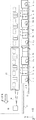
図8に示すように、停止目標位置P0に隣接した固定部4には、データ処理装置7が取り付けられている。このデータ処理装置7が取り付けられた固定部4から、扉体6a,6bを挟んでX軸方向に配置された固定部4には、第N光電センサ13nが取り付けられている。また、第N光電センサ13nが取り付けられた固定部4から、扉体6a,6bを挟んで+X方向に配置された複数の固定部4にはそれぞれ、第N−1光電センサ13n-1から第1光電センサ13aまでのn−1個の光電センサが1つずつ取り付けられている。第1光電センサ13aから第N光電センサ13nまでのN個の光電センサ11のことを、光電センサ群14と称する。 As shown in FIG. 8, a data processing device 7 is attached to the fixed portion 4 adjacent to the stop target position P0. The Nth photoelectric sensor 13n is attached to the fixed portion 4 arranged in the X-axis direction with the door bodies 6a and 6b interposed therebetween from the fixed portion 4 to which the data processing device 7 is attached. Further, from the fixed portion 4 to which the Nth photoelectric sensor 13n is attached, to the plurality of fixed portions 4 arranged in the + X direction with the door bodies 6a and 6b interposed therebetween, the N-1 photoelectric sensor 13n-1 to the first. 1 n-1 photoelectric sensors up to the photoelectric sensor 13a are attached one by one. The N photoelectric sensors 11 from the first photoelectric sensor 13a to the Nth photoelectric sensor 13n are referred to as a photoelectric sensor group 14.

実施の形態3における停止位置検知システムの動作については、在否検知センサ51としての光電センサ群14の動作以外、上述の実施の形態1の動作と同様である。 The operation of the stop position detection system in the third embodiment is the same as the operation of the first embodiment described above, except for the operation of the photoelectric sensor group 14 as the presence / absence detection sensor 51.

光電センサ群14の動作について、図9を用いて説明する。プラットホーム2に接した軌道上へ列車20が進入すると、光電センサ群14の各光電センサ11は順番に列車20を検知し、オンレベルの在否検知信号を出力する。図9(A)に示すように、列車20が停止目標位置P0に向かってプラットホーム2に接した軌道上に進入すると、第1光電センサ13aが列車20を検知し、オンレベルの在否検知信号を出力する。第2光電センサ13b、第3光電センサ13c、・・・、第N光電センサ13nは、列車20を検知していないので、オフレベルの在否検知信号を出力する。 The operation of the photoelectric sensor group 14 will be described with reference to FIG. When the train 20 enters the track in contact with the platform 2, each photoelectric sensor 11 of the photoelectric sensor group 14 sequentially detects the train 20 and outputs an on-level presence / absence detection signal. As shown in FIG. 9A, when the train 20 enters the track in contact with the platform 2 toward the stop target position P0, the first photoelectric sensor 13a detects the train 20 and an on-level presence / absence detection signal. Is output. Since the second photoelectric sensor 13b, the third photoelectric sensor 13c, ..., The Nth photoelectric sensor 13n does not detect the train 20, it outputs an off-level presence / absence detection signal.

さらに、列車20が進行すると、図9(B)に示すように、第2光電センサ13bが列車20を検知し、オンレベルの検知信号を出力する。第3光電センサ13c、・・・、第N光電センサ13nは、列車20を検知していないので、オフレベルの在否検知信号を出力する。列車20が停止目標位置P0に向かって進行することに伴い、光電センサ群14の各光電センサは順番に、列車20を検知しオンレベルの在否検知信号を出力する。最終的には、図9(C)に示すように、第1光電センサ13aから第N光電センサ13nまでの全ての光電センサが列車20を検知しオンレベルの在否検知信号を出力する。 Further, as the train 20 advances, as shown in FIG. 9B, the second photoelectric sensor 13b detects the train 20 and outputs an on-level detection signal. Since the third photoelectric sensor 13c, ..., The Nth photoelectric sensor 13n does not detect the train 20, it outputs an off-level presence / absence detection signal. As the train 20 advances toward the stop target position P0, each photoelectric sensor of the photoelectric sensor group 14 sequentially detects the train 20 and outputs an on-level presence / absence detection signal. Finally, as shown in FIG. 9C, all the photoelectric sensors from the first photoelectric sensor 13a to the Nth photoelectric sensor 13n detect the train 20 and output an on-level presence / absence detection signal.

データ処理装置7には、図10に示すような停止位置判定プログラムがインストールされている。
データ処理装置7は、複数光電センサ停止位置判定プログラムを、例えば、図示せぬ入線センサが列車20の進入を検知したときに起動する。
データ処理装置7は、停止位置判定プログラムを起動すると、列車情報装置から列車の車種データを取得する。データ処理装置7は、車種データから車種ごとに定められたプラットホーム2での停止目標位置P0と、停止誤差位置P1,P2を読み出し、定位置停止範囲P1〜P2を設定する。
A stop position determination program as shown in FIG. 10 is installed in the data processing device 7.
The data processing device 7 activates the plurality of photoelectric sensor stop position determination programs, for example, when an incoming line sensor (not shown) detects the approach of the train 20.
When the data processing device 7 activates the stop position determination program, the data processing device 7 acquires train vehicle type data from the train information device. The data processing device 7 reads out the stop target position P0 and the stop error positions P1 and P2 on the platform 2 determined for each vehicle type from the vehicle type data, and sets the fixed-position stop ranges P1 to P2.

次に、データ処理装置7は、定位置停止センサ出力取得関数を呼び出し、図5に示す処理により、定位置判定信号と停止判定信号とを取得する(ステップS41)。次に、データ処理装置7は、光電センサ群14から検知情報を含む在否検知信号をタイムスタンプと共に取得する(ステップS42)。 Next, the data processing device 7 calls the fixed-position stop sensor output acquisition function, and acquires the fixed-position determination signal and the stop determination signal by the process shown in FIG. 5 (step S41). Next, the data processing device 7 acquires the presence / absence detection signal including the detection information from the photoelectric sensor group 14 together with the time stamp (step S42).

データ処理装置7は、定位置判定信号と停止判定信号とが共にオンであるか否かを判定する(ステップS43)。共にオンであれば、ステップS44に進み、少なくとも1つがオフであれば、ステップS41に戻る。 The data processing device 7 determines whether or not both the fixed position determination signal and the stop determination signal are ON (step S43). If both are on, the process proceeds to step S44, and if at least one is off, the process returns to step S41.

ステップS44において、データ処理装置7は、第1光電センサ13aから第N光電センサ13nが順番にオンレベルの検知信号を出力したか否かを判定する(ステップS44)。なお、第1光電センサ13aから第N光電センサ13nが順番にオンレベルの検知信号を出力したか否かについては、一定の誤検出を認める基準を設定しておくことが望ましい。 In step S44, the data processing device 7 determines whether or not the first photoelectric sensor 13a to the Nth photoelectric sensor 13n sequentially output an on-level detection signal (step S44). Regarding whether or not the first photoelectric sensor 13a to the Nth photoelectric sensor 13n sequentially output the on-level detection signal, it is desirable to set a standard for allowing a certain false detection.

データ処理装置7は、第1光電センサ13aから第N光電センサ13nが順番にオンレベルの検知信号を出力したと判定すると(ステップS44:YES)、停止確認信号を外部機器60に出力する(ステップS45)。 When the data processing device 7 determines that the first photoelectric sensor 13a to the Nth photoelectric sensor 13n sequentially output the on-level detection signal (step S44: YES), the data processing device 7 outputs the stop confirmation signal to the external device 60 (step). S45).

一方、データ処理装置7は、第1光電センサ13aから第N光電センサ13nが順番にオンレベルの検知信号を出力していない、例えば、第N光電センサ13nが未だオフである、或いは、第N光電センサ13nだけがオンであるといった場合(ステップS44:NO)、処理をステップS41に戻す。 On the other hand, in the data processing device 7, the first photoelectric sensor 13a to the Nth photoelectric sensor 13n do not sequentially output the on-level detection signal, for example, the Nth photoelectric sensor 13n is still off, or the Nth photoelectric sensor 13n is still off. If only the photoelectric sensor 13n is on (step S44: NO), the process returns to step S41.

このように、本発明の実施の形態3に係る停止位置検知システムは、定位置停止センサ50と光電センサ群14の両方を用いて列車20が定停止位置に停止していることを判定する。このため、定位置停止センサ50だけで列車20が定停止位置に停止していることを判定する場合に比べて判定条件が厳しくなるので、信頼性の高い定位置停止判定を行うことができる。 As described above, the stop position detection system according to the third embodiment of the present invention uses both the fixed-position stop sensor 50 and the photoelectric sensor group 14 to determine that the train 20 is stopped at the fixed stop position. Therefore, the determination condition becomes stricter than the case where the train 20 is determined to be stopped at the fixed stop position only by the fixed position stop sensor 50, so that the fixed position stop determination can be performed with high reliability.

また、定位置停止センサ50を既設している場合には、光電センサ群14を可動式ホーム柵1に取り付けるだけで本実施の形態に係る停止位置検知システムを用いることができる。そのため、信頼性の高い定位置停止判定を行う停止位置検知システムを、簡易に導入することができる。 Further, when the fixed-position stop sensor 50 is already installed, the stop position detection system according to the present embodiment can be used only by attaching the photoelectric sensor group 14 to the movable platform fence 1. Therefore, it is possible to easily introduce a stop position detection system that performs a highly reliable fixed-position stop determination.

(変形例)
この実施の形態3において用いられる光電センサは、実施の形態2で示した光電センサ11と同様のものであるが、これに限らず、平面センサ12を用いて構成してもよい。
(Modification example)
The photoelectric sensor used in the third embodiment is the same as the photoelectric sensor 11 shown in the second embodiment, but the present invention is not limited to this, and the planar sensor 12 may be used.

(実施の形態4)
この発明の実施の形態4における停止位置検知システムについて、図6および図11を用いて説明する。図6(A)において、固定部4に取り付けられた光電センサ11の代わりに、カメラ15を備える。それ以外の構成については、実施の形態2で説明した通りである。カメラ15は、軌道側の画像を周期的に採取し、データ処理装置7へ画像データを出力する。
(Embodiment 4)
The stop position detection system according to the fourth embodiment of the present invention will be described with reference to FIGS. 6 and 11. In FIG. 6A, a camera 15 is provided in place of the photoelectric sensor 11 attached to the fixed portion 4. The other configurations are as described in the second embodiment. The camera 15 periodically collects an image on the orbital side and outputs the image data to the data processing device 7.

実施の形態4における停止位置検知システムの動作については、在否検知センサ51として光電センサ11を用いる以外、上述の実施の形態1の動作と同様である。 The operation of the stop position detection system in the fourth embodiment is the same as the operation of the first embodiment described above except that the photoelectric sensor 11 is used as the presence / absence detection sensor 51.

データ処理装置7には、図10に示す停止位置判定プログラムがインストールされている。
データ処理装置7は、この停止位置判定プログラムを、例えば、図示しないセンサが軌道上へ列車20が進入したことを検知したことに応答して、起動する。
データ処理装置7は、停止位置判定プログラムを起動すると、列車情報装置から列車の車種データを取得する。データ処理装置7は、車種データから車種ごとに定められたプラットホーム2での停止目標位置P0と、停止誤差位置P1,P2を読み出し、定位置停止範囲P1〜P2を設定する。
The stop position determination program shown in FIG. 10 is installed in the data processing device 7.
The data processing device 7 activates this stop position determination program in response to, for example, a sensor (not shown) detecting that the train 20 has entered the track.
When the data processing device 7 activates the stop position determination program, the data processing device 7 acquires train vehicle type data from the train information device. The data processing device 7 reads out the stop target position P0 and the stop error positions P1 and P2 on the platform 2 determined for each vehicle type from the vehicle type data, and sets the fixed-position stop ranges P1 to P2.

続いて、データ処理装置7は、図5に示す定位置停止センサ出力取得関数を呼び出し、定位置停止センサ50から定位置判定信号と停止判定信号とを取得する(ステップS51)。
続いて、データ処理装置7は、カメラ15から軌道側の画像データを取得する(ステップS52)。
データ処理装置7は、カメラ15から取得した画像データが、入線予定の列車20の車体の画像に一致するか否かを判別する(ステップS53)。例えば、データ処理装置7は、画像データ中の列車20に対応する画素の数を求める。例えば、車体に反応した色及び明るさの画素の数を求める。例えば、黒色または黒色に類似した暗色の画素の画素数を取得する。画像データから取得した車体の画素数が、予め定められた車体を識別するための基準となる基準画素数以上であれば、軌道上に列車20が存在するものと判定し(ステップS53:YES)、ステップS54にすすむ。画像データから取得した車体の画素数が基準画素数以下であれば、軌道上に列車20が存在しないものと判定し(ステップS53:NO)ステップS51へ戻る。
Subsequently, the data processing device 7 calls the fixed-position stop sensor output acquisition function shown in FIG. 5, and acquires the fixed-position determination signal and the stop determination signal from the fixed-position stop sensor 50 (step S51).
Subsequently, the data processing device 7 acquires image data on the orbit side from the camera 15 (step S52).
The data processing device 7 determines whether or not the image data acquired from the camera 15 matches the image of the vehicle body of the train 20 scheduled to enter the line (step S53). For example, the data processing device 7 obtains the number of pixels corresponding to the train 20 in the image data. For example, the number of pixels of color and brightness that reacts to the vehicle body is obtained. For example, the number of pixels of black or a dark-colored pixel similar to black is acquired. If the number of pixels of the vehicle body acquired from the image data is equal to or greater than the predetermined reference number of pixels for identifying the vehicle body, it is determined that the train 20 exists on the track (step S53: YES). , Proceed to step S54. If the number of pixels of the vehicle body acquired from the image data is equal to or less than the reference number of pixels, it is determined that the train 20 does not exist on the track (step S53: NO), and the process returns to step S51.

データ処理装置7は、ステップS54において、定位置判定信号と停止判定信号とが共にオンレベルであれば、列車20が定停止位置に停止しているものと判定し(ステップS54:YES)、停止確認信号を外部機器60に出力する(ステップS55)。
一方、データ処理装置7は、定位置判定信号と停止判定信号の一方又は両方がオンレベルでなければ、列車20が定停止位置に停止していないものと判定して(ステップS54:NO)、処理をステップS51に戻す。
If both the fixed position determination signal and the stop determination signal are on-level in step S54, the data processing device 7 determines that the train 20 has stopped at the fixed stop position (step S54: YES), and stops. The confirmation signal is output to the external device 60 (step S55).
On the other hand, the data processing device 7 determines that the train 20 has not stopped at the fixed stop position unless one or both of the fixed position determination signal and the stop determination signal is on level (step S54: NO). The process returns to step S51.

このように、本実施の形態に係る停止位置検知システムは、定位置停止センサ50とカメラ15の両方を用いて列車20の先頭部が定停止位置に停止していることを判定する。このため、定位置停止センサ50だけで列車20の先頭部が定停止位置に停止していることを判定する場合に比べて判定条件が厳しくなり、信頼性の高い定位置停止判定を行うことができる。 As described above, the stop position detection system according to the present embodiment uses both the fixed-position stop sensor 50 and the camera 15 to determine that the head portion of the train 20 is stopped at the fixed-stop position. Therefore, the determination condition becomes stricter than the case where it is determined that the head portion of the train 20 is stopped at the fixed stop position only by the fixed position stop sensor 50, and it is possible to perform a highly reliable fixed position stop determination. can.

また、定位置停止センサ50を既設している場合には、カメラ15を可動式ホーム柵1に取り付けるだけで本実施の形態に係る停止位置検知システムを用いることができる。そのため、信頼性の高い定位置停止判定を行う停止位置検知システムを、簡易に導入することができる。 Further, when the fixed-position stop sensor 50 is already installed, the stop position detection system according to the present embodiment can be used simply by attaching the camera 15 to the movable platform fence 1. Therefore, it is possible to easily introduce a stop position detection system that performs a highly reliable fixed-position stop determination.

(変形例)
軌道上の列車20の在否を検知するためにカメラ15を用いる場合には、可動式ホーム柵1の固定部4に取り付ける(または内蔵する)だけではなく、ホームの屋根に天吊りにすることも可能である。
また、上記実施の形態においては、データ処理装置7は、画像データ中の列車20に対応する画素の数を求めていたが、パターンマッチングの手法を用いてもよい。
(Modification example)
When the camera 15 is used to detect the presence or absence of the train 20 on the track, it should not only be attached (or built in) to the fixed portion 4 of the movable platform fence 1 but also suspended from the roof of the platform. Is also possible.
Further, in the above embodiment, the data processing device 7 has obtained the number of pixels corresponding to the train 20 in the image data, but a pattern matching method may be used.

なお、本発明の技術的範囲は、上記実施の形態と変形例によっては限定されない。本発明は特許請求の範囲に記載された技術的思想の限りにおいて、自由に応用、変形あるいは改良して、実施することができる。 The technical scope of the present invention is not limited to the above embodiments and modifications. The present invention can be freely applied, modified or improved as far as the technical idea described in the claims is concerned.

本発明は、可動式ホーム柵に好適に利用することができる。 The present invention can be suitably used for movable platform fences.

1 可動式ホーム柵、2 プラットホーム、4 固定部、5 乗降通路、6a,6b 扉体、7 データ処理装置、8 RFIDリーダ、9 アンテナ、11 光電センサ、12 平面センサ、14 光電センサ群、15 カメラ、20 列車、23 RFIDタグ、50 定位置停止センサ、501 第1距離センサ、502 第2距離センサ、503 制御部、51 在否検知センサ、60 外部機器 1 Movable platform fence, 2 platform, 4 fixed part, 5 boarding / alighting passage, 6a, 6b door body, 7 data processing device, 8 RFID reader, 9 antenna, 11 photoelectric sensor, 12 plane sensor, 14 photoelectric sensor group, 15 camera , 20 trains, 23 RFID tags, 50 fixed position stop sensor, 501 first distance sensor, 502 second distance sensor, 503 control unit, 51 presence / absence detection sensor, 60 external device

Claims (3)

軌道上の列車の定停止位置よりも進行方向前方又は後方に設置され、前記列車の位置と前記列車の状態とを検出する定位置停止判別手段と、
前記定停止位置において、前記列車の在否を検知する在否検知手段と、
前記定位置停止判別手段で検出された前記列車の位置が予め設定された範囲にあり且つ前記列車が停止状態にあり、かつ、前記在否検知手段が前記列車の存在を検知している場合に、前記列車が存在していることを示す情報を外部機器に出力する判別手段と、を備え、
前記列車には車両情報を保持する媒体が配置されており、
前記在否検知手段は、前記媒体から車両情報を取得する在否検知センサを備え、
前記判別手段は、取得した前記車両情報の示す列車が、入線予定の列車と一致するか否かを判定し、一致する場合に列車が存在していると判定し、
さらに、
前記外部機器は、前記軌道に隣接するプラットホームに設置された可動式ホーム柵であり、
前記可動式ホーム柵は、開閉自在の扉体と、前記扉体が収納される戸袋と、前記扉体を制御する制御部とを備え、
前記在否検知手段は、前記可動式ホーム柵の戸袋に取り付けられて、車両の在否を判定するための情報を収拾するセンサを備え、
前記可動式ホーム柵の制御部は、前記判別手段から出力された判定結果に基づいて、当該可動式ホーム柵の扉体を制御する、
停止位置検知システム。
A fixed-position stop determination means that is installed in front of or behind the fixed-stop position of a train on the track and detects the position of the train and the state of the train.
At the fixed stop position, the presence / absence detecting means for detecting the presence / absence of the train and the presence / absence detecting means
When the position of the train detected by the fixed-position stop determination means is within a preset range, the train is in a stopped state, and the presence / absence detecting means detects the presence of the train. , A discriminating means for outputting information indicating the existence of the train to an external device.
A medium for holding vehicle information is placed on the train.
The presence / absence detection means includes a presence / absence detection sensor that acquires vehicle information from the medium.
It said discriminating means, trains indicated by the acquired vehicle information, determines whether or not to match the train incoming appointment, if it matches is determined that the train is present,
Moreover,
The external device is a movable platform fence installed on a platform adjacent to the track.
The movable platform fence includes a door body that can be opened and closed, a door pocket in which the door body is housed, and a control unit that controls the door body.
The presence / absence detecting means includes a sensor attached to the door pocket of the movable platform fence and collecting information for determining the presence / absence of a vehicle.
The control unit of the movable platform fence controls the door body of the movable platform fence based on the determination result output from the determination means.
Stop position detection system.
前記在否検知センサは平面センサを備える、請求項に記載の停止位置検知システム。 The stop position detection system according to claim 1 , wherein the presence / absence detection sensor includes a flat surface sensor. 軌道上の列車の定停止位置よりも進行方向前方又は後方に設置され、前記列車の位置と前記列車の状態とを検出する定位置停止判別手段と、
前記定停止位置において、前記列車の在否を検知する在否検知手段と、
前記定位置停止判別手段で検出された前記列車の位置が予め設定された範囲にあり且つ前記列車が停止状態にあり、かつ、前記在否検知手段が前記列車の存在を検知している場合に、前記列車が存在していることを示す情報を外部機器に出力する判別手段と、を備え、
前記外部機器は、前記軌道に隣接するプラットホームに設置された可動式ホーム柵であり、
前記可動式ホーム柵は、開閉自在の扉体と、前記扉体が収納される戸袋と、前記扉体を制御する制御部とを備え、
前記在否検知手段は、前記可動式ホーム柵の戸袋に取り付けられて、前記列車に配置された車両情報を保持する媒体から前記両情報を収拾するセンサを備え、
前記判別手段は、収拾した前記車両情報の示す列車が、入線予定の列車と一致するか否かを判定し、一致する場合に列車が存在していると判定し、
前記可動式ホーム柵の制御部は、前記判別手段から出力された判定結果に基づいて、当該可動式ホーム柵の扉体を制御する、
停止位置検知システム。
A fixed-position stop determination means that is installed in front of or behind the fixed-stop position of a train on the track and detects the position of the train and the state of the train.
At the fixed stop position, the presence / absence detecting means for detecting the presence / absence of the train and the presence / absence detecting means
When the position of the train detected by the fixed-position stop determination means is within a preset range, the train is in a stopped state, and the presence / absence detecting means detects the presence of the train. , A discriminating means for outputting information indicating the existence of the train to an external device.
The external device is a movable platform fence installed on a platform adjacent to the track.
The movable platform fence includes a door body that can be opened and closed, a door pocket in which the door body is housed, and a control unit that controls the door body.
The presence or absence detecting means, said movably mounted platform fence of the door pocket, provided with a sensor for settling the vehicle both information from a medium that holds a vehicle information arranged in the train,
The discriminating means determines whether or not the train indicated by the collected vehicle information matches the train scheduled to enter, and if so, determines that a train exists.
The control unit of the movable platform fence controls the door body of the movable platform fence based on the determination result output from the determination means.
Stop position detection system.
JP2017148671A 2017-07-31 2017-07-31 Stop position detection system Active JP6976099B2 (en)

Priority Applications (1)

Application Number Priority Date Filing Date Title
JP2017148671A JP6976099B2 (en) 2017-07-31 2017-07-31 Stop position detection system

Applications Claiming Priority (1)

Application Number Priority Date Filing Date Title
JP2017148671A JP6976099B2 (en) 2017-07-31 2017-07-31 Stop position detection system

Publications (3)

Publication Number Publication Date
JP2019026127A JP2019026127A (en) 2019-02-21
JP2019026127A5 JP2019026127A5 (en) 2020-08-13
JP6976099B2 true JP6976099B2 (en) 2021-12-08

Family

ID=65477521

Family Applications (1)

Application Number Title Priority Date Filing Date
JP2017148671A Active JP6976099B2 (en) 2017-07-31 2017-07-31 Stop position detection system

Country Status (1)

Country Link
JP (1) JP6976099B2 (en)

Families Citing this family (2)

* Cited by examiner, † Cited by third party
Publication number Priority date Publication date Assignee Title
JP7236941B2 (en) * 2019-06-19 2023-03-10 三菱電機株式会社 Stop position determination device, platform door control device, and platform door system
JP7456855B2 (en) * 2020-06-01 2024-03-27 日本信号株式会社 Vehicle location system

Family Cites Families (7)

* Cited by examiner, † Cited by third party
Publication number Priority date Publication date Assignee Title
JP2700373B2 (en) * 1993-03-29 1998-01-21 小糸工業株式会社 Train stop position detection device
JP4870370B2 (en) * 2005-03-23 2012-02-08 株式会社神戸製鋼所 Home door opening / closing control device and control program for home door device
JP5041675B2 (en) * 2005-05-24 2012-10-03 日本信号株式会社 Railroad crossing control device
JP5517706B2 (en) * 2010-04-02 2014-06-11 日本信号株式会社 Home door control system
JP5992673B2 (en) * 2011-09-16 2016-09-14 日本信号株式会社 Platform door device with movable step
JP2013203118A (en) * 2012-03-27 2013-10-07 Japan Transport Engineering Co Movable platform gate apparatus and controlling method of the same
JP6502107B2 (en) * 2015-01-30 2019-04-17 三菱重工交通機器エンジニアリング株式会社 Home door control device and home door control method

Also Published As

Publication number Publication date
JP2019026127A (en) 2019-02-21

Similar Documents

Publication Publication Date Title
CN1956908B (en) Passenger guiding system for a passenger transportation system
JP3206414B2 (en) Vehicle type identification device
US9956940B2 (en) Method and device for actuating a closing element for a vehicle
US20210396684A1 (en) Assembly for detecting defects on a motor vehicle bodywork
JP4971874B2 (en) Position detection device
JP4962742B2 (en) Mobile system
JP6976099B2 (en) Stop position detection system
CN106875498A (en) A kind of ETC system that can be accurately positioned vehicle and dynamic setting communication zone
US11157746B2 (en) Method and system for detecting an elevated object situated within a parking facility
CN205334557U (en) ETC system of ability accurate positioning vehicle and dynamically arrange communication zone
JP6081549B1 (en) Vehicle type identification device, train fixed position stop detection device, and platform door control device
AU2017442202A1 (en) Rain filtering techniques for autonomous vehicle
JP2001264013A (en) Vehicle door opening/closing detecting method, platform door opening/closing method, vehicle door opening/closing detecting system, and platform door opening/closing system
JP2017218151A (en) Platform door control device and platform door control method
KR101962403B1 (en) An Apparatus and A Method For Stop Guidance In Position Based On Phased-Array Optical Beams
KR20180042495A (en) Monitoring AND safety System for human body and object of platform screen door
CN109655796A (en) Axle offset decision maker
JP2016141213A (en) Platform door control device and platform door control method
JP6934799B2 (en) Platform screen door system
JP7108115B2 (en) Vehicle door open/close detector
JP6966280B2 (en) Lane control devices, wireless communication systems, wireless communication methods and programs
CN101401138B (en) Improved aircraft docking system
JP6999292B2 (en) Movable home fence and movable home fence row
JP2014084063A (en) Vehicle information display system, and vehicle stop position display system
JP4368318B2 (en) Mobile robot

Legal Events

Date Code Title Description
A521 Written amendment

Free format text: JAPANESE INTERMEDIATE CODE: A523

Effective date: 20200701

A621 Written request for application examination

Free format text: JAPANESE INTERMEDIATE CODE: A621

Effective date: 20200701

A977 Report on retrieval

Free format text: JAPANESE INTERMEDIATE CODE: A971007

Effective date: 20210414

A131 Notification of reasons for refusal

Free format text: JAPANESE INTERMEDIATE CODE: A131

Effective date: 20210420

A521 Written amendment

Free format text: JAPANESE INTERMEDIATE CODE: A523

Effective date: 20210616

A131 Notification of reasons for refusal

Free format text: JAPANESE INTERMEDIATE CODE: A131

Effective date: 20210706

A521 Written amendment

Free format text: JAPANESE INTERMEDIATE CODE: A523

Effective date: 20210901

TRDD Decision of grant or rejection written
A01 Written decision to grant a patent or to grant a registration (utility model)

Free format text: JAPANESE INTERMEDIATE CODE: A01

Effective date: 20211012

A61 First payment of annual fees (during grant procedure)

Free format text: JAPANESE INTERMEDIATE CODE: A61

Effective date: 20211109

R150 Certificate of patent or registration of utility model

Ref document number: 6976099

Country of ref document: JP

Free format text: JAPANESE INTERMEDIATE CODE: R150