JP6975729B2 - Sample tube with integrated mixing plunger head - Google Patents
Sample tube with integrated mixing plunger head Download PDFInfo
- Publication number
- JP6975729B2 JP6975729B2 JP2018566889A JP2018566889A JP6975729B2 JP 6975729 B2 JP6975729 B2 JP 6975729B2 JP 2018566889 A JP2018566889 A JP 2018566889A JP 2018566889 A JP2018566889 A JP 2018566889A JP 6975729 B2 JP6975729 B2 JP 6975729B2
- Authority
- JP
- Japan
- Prior art keywords
- plunger head
- cap
- shaft
- container
- insertion portion
- Prior art date
- Legal status (The legal status is an assumption and is not a legal conclusion. Google has not performed a legal analysis and makes no representation as to the accuracy of the status listed.)
- Active
Links
Images


Classifications
-
- B—PERFORMING OPERATIONS; TRANSPORTING
- B01—PHYSICAL OR CHEMICAL PROCESSES OR APPARATUS IN GENERAL
- B01L—CHEMICAL OR PHYSICAL LABORATORY APPARATUS FOR GENERAL USE
- B01L3/00—Containers or dishes for laboratory use, e.g. laboratory glassware; Droppers
- B01L3/50—Containers for the purpose of retaining a material to be analysed, e.g. test tubes
- B01L3/508—Containers for the purpose of retaining a material to be analysed, e.g. test tubes rigid containers not provided for above
- B01L3/5082—Test tubes per se
- B01L3/50825—Closing or opening means, corks, bungs
-
- A—HUMAN NECESSITIES
- A61—MEDICAL OR VETERINARY SCIENCE; HYGIENE
- A61B—DIAGNOSIS; SURGERY; IDENTIFICATION
- A61B10/00—Other methods or instruments for diagnosis, e.g. instruments for taking a cell sample, for biopsy, for vaccination diagnosis; Sex determination; Ovulation-period determination; Throat striking implements
- A61B10/0045—Devices for taking samples of body liquids
-
- B—PERFORMING OPERATIONS; TRANSPORTING
- B01—PHYSICAL OR CHEMICAL PROCESSES OR APPARATUS IN GENERAL
- B01L—CHEMICAL OR PHYSICAL LABORATORY APPARATUS FOR GENERAL USE
- B01L3/00—Containers or dishes for laboratory use, e.g. laboratory glassware; Droppers
-
- B—PERFORMING OPERATIONS; TRANSPORTING
- B01—PHYSICAL OR CHEMICAL PROCESSES OR APPARATUS IN GENERAL
- B01L—CHEMICAL OR PHYSICAL LABORATORY APPARATUS FOR GENERAL USE
- B01L3/00—Containers or dishes for laboratory use, e.g. laboratory glassware; Droppers
- B01L3/50—Containers for the purpose of retaining a material to be analysed, e.g. test tubes
- B01L3/502—Containers for the purpose of retaining a material to be analysed, e.g. test tubes with fluid transport, e.g. in multi-compartment structures
-
- B—PERFORMING OPERATIONS; TRANSPORTING
- B65—CONVEYING; PACKING; STORING; HANDLING THIN OR FILAMENTARY MATERIAL
- B65D—CONTAINERS FOR STORAGE OR TRANSPORT OF ARTICLES OR MATERIALS, e.g. BAGS, BARRELS, BOTTLES, BOXES, CANS, CARTONS, CRATES, DRUMS, JARS, TANKS, HOPPERS, FORWARDING CONTAINERS; ACCESSORIES, CLOSURES, OR FITTINGS THEREFOR; PACKAGING ELEMENTS; PACKAGES
- B65D25/00—Details of other kinds or types of rigid or semi-rigid containers
- B65D25/02—Internal fittings
- B65D25/04—Partitions
- B65D25/08—Partitions with provisions for removing or destroying, e.g. to facilitate mixing of contents
- B65D25/085—Partitions with provisions for removing or destroying, e.g. to facilitate mixing of contents the partition being in the form of a plug or the like which is dislodged by means of a plunger rod or the like pushing the plug down
-
- B—PERFORMING OPERATIONS; TRANSPORTING
- B65—CONVEYING; PACKING; STORING; HANDLING THIN OR FILAMENTARY MATERIAL
- B65D—CONTAINERS FOR STORAGE OR TRANSPORT OF ARTICLES OR MATERIALS, e.g. BAGS, BARRELS, BOTTLES, BOXES, CANS, CARTONS, CRATES, DRUMS, JARS, TANKS, HOPPERS, FORWARDING CONTAINERS; ACCESSORIES, CLOSURES, OR FITTINGS THEREFOR; PACKAGING ELEMENTS; PACKAGES
- B65D51/00—Closures not otherwise provided for
- B65D51/002—Closures to be pierced by an extracting-device for the contents and fixed on the container by separate retaining means
-
- B—PERFORMING OPERATIONS; TRANSPORTING
- B01—PHYSICAL OR CHEMICAL PROCESSES OR APPARATUS IN GENERAL
- B01L—CHEMICAL OR PHYSICAL LABORATORY APPARATUS FOR GENERAL USE
- B01L2200/00—Solutions for specific problems relating to chemical or physical laboratory apparatus
- B01L2200/06—Fluid handling related problems
- B01L2200/0621—Control of the sequence of chambers filled or emptied
-
- B—PERFORMING OPERATIONS; TRANSPORTING
- B01—PHYSICAL OR CHEMICAL PROCESSES OR APPARATUS IN GENERAL
- B01L—CHEMICAL OR PHYSICAL LABORATORY APPARATUS FOR GENERAL USE
- B01L2200/00—Solutions for specific problems relating to chemical or physical laboratory apparatus
- B01L2200/06—Fluid handling related problems
- B01L2200/0689—Sealing
-
- B—PERFORMING OPERATIONS; TRANSPORTING
- B01—PHYSICAL OR CHEMICAL PROCESSES OR APPARATUS IN GENERAL
- B01L—CHEMICAL OR PHYSICAL LABORATORY APPARATUS FOR GENERAL USE
- B01L2300/00—Additional constructional details
- B01L2300/04—Closures and closing means
- B01L2300/041—Connecting closures to device or container
- B01L2300/042—Caps; Plugs
-
- B—PERFORMING OPERATIONS; TRANSPORTING
- B01—PHYSICAL OR CHEMICAL PROCESSES OR APPARATUS IN GENERAL
- B01L—CHEMICAL OR PHYSICAL LABORATORY APPARATUS FOR GENERAL USE
- B01L2300/00—Additional constructional details
- B01L2300/04—Closures and closing means
- B01L2300/041—Connecting closures to device or container
- B01L2300/044—Connecting closures to device or container pierceable, e.g. films, membranes
-
- B—PERFORMING OPERATIONS; TRANSPORTING
- B01—PHYSICAL OR CHEMICAL PROCESSES OR APPARATUS IN GENERAL
- B01L—CHEMICAL OR PHYSICAL LABORATORY APPARATUS FOR GENERAL USE
- B01L2300/00—Additional constructional details
- B01L2300/04—Closures and closing means
- B01L2300/041—Connecting closures to device or container
- B01L2300/045—Connecting closures to device or container whereby the whole cover is slidable
-
- B—PERFORMING OPERATIONS; TRANSPORTING
- B01—PHYSICAL OR CHEMICAL PROCESSES OR APPARATUS IN GENERAL
- B01L—CHEMICAL OR PHYSICAL LABORATORY APPARATUS FOR GENERAL USE
- B01L2300/00—Additional constructional details
- B01L2300/04—Closures and closing means
- B01L2300/046—Function or devices integrated in the closure
-
- B—PERFORMING OPERATIONS; TRANSPORTING
- B01—PHYSICAL OR CHEMICAL PROCESSES OR APPARATUS IN GENERAL
- B01L—CHEMICAL OR PHYSICAL LABORATORY APPARATUS FOR GENERAL USE
- B01L2300/00—Additional constructional details
- B01L2300/08—Geometry, shape and general structure
- B01L2300/0832—Geometry, shape and general structure cylindrical, tube shaped
-
- B—PERFORMING OPERATIONS; TRANSPORTING
- B01—PHYSICAL OR CHEMICAL PROCESSES OR APPARATUS IN GENERAL
- B01L—CHEMICAL OR PHYSICAL LABORATORY APPARATUS FOR GENERAL USE
- B01L2300/00—Additional constructional details
- B01L2300/08—Geometry, shape and general structure
- B01L2300/0861—Configuration of multiple channels and/or chambers in a single devices
- B01L2300/087—Multiple sequential chambers
-
- B—PERFORMING OPERATIONS; TRANSPORTING
- B01—PHYSICAL OR CHEMICAL PROCESSES OR APPARATUS IN GENERAL
- B01L—CHEMICAL OR PHYSICAL LABORATORY APPARATUS FOR GENERAL USE
- B01L2300/00—Additional constructional details
- B01L2300/12—Specific details about materials
- B01L2300/123—Flexible; Elastomeric
-
- B—PERFORMING OPERATIONS; TRANSPORTING
- B01—PHYSICAL OR CHEMICAL PROCESSES OR APPARATUS IN GENERAL
- B01L—CHEMICAL OR PHYSICAL LABORATORY APPARATUS FOR GENERAL USE
- B01L2400/00—Moving or stopping fluids
- B01L2400/04—Moving fluids with specific forces or mechanical means
- B01L2400/0475—Moving fluids with specific forces or mechanical means specific mechanical means and fluid pressure
- B01L2400/0478—Moving fluids with specific forces or mechanical means specific mechanical means and fluid pressure pistons
Description
本願は、2017年1月3日に出願された米国特許出願第62/441,921号に対する優先権を主張する、2017年12月13日に出願された米国特許出願第15/841,113号に対する優先権を主張するものであり、これらの出願の全体が、参照によって本明細書に組み込まれている。 This application claims priority over US Patent Application No. 62 / 441,921 filed January 3, 2017, US Patent Application No. 15 / 841,113 filed December 13, 2017. All of these applications are incorporated herein by reference.
いくつかの化学的解析システムおよび生物学的解析システムでは、検体試料はしばしば、例えばバイアル等の、その中に流体を有し得る小さい容器内に置かれ得る。そして、そのような試料は、流体中でより均等に試料を分散または分配するため、および/または、試薬であり得る流体と試料との間の完全反応を促進するために、そのような容器の内容物と混合され得る。 In some chemical and biological analysis systems, the sample sample can often be placed in a small container, such as a vial, which may have fluid in it. And such a sample is in such a container in order to disperse or distribute the sample more evenly in the fluid and / or to facilitate a complete reaction between the fluid and the sample, which may be a reagent. Can be mixed with the contents.
試料容器の中に含まれた材料の向上した混合を提供するために使用され得る特徴を含む、新しいタイプの試料容器を実施する概念および技術を、本明細書のいくつかの実施例において開示する。 The concepts and techniques for implementing new types of sample containers, including features that can be used to provide an improved mix of materials contained within the sample container, are disclosed in some examples herein. ..
本明細書に記載した主題の一つ以上の実施態様の詳細は、添付の図面及び以下の説明において述べられる。他の特徴、態様および利点は、明細書、図面および請求項から、明確になる。以下の図面の相対寸法は、明確に示さない限り正しい縮尺では示していないことに留意されたい。 Details of one or more embodiments of the subject matter described herein are set forth in the accompanying drawings and the following description. Other features, embodiments and advantages will be apparent from the description, drawings and claims. Note that the relative dimensions in the drawings below are not shown to the correct scale unless explicitly stated.
いくつかの実施態様では、装置には、ふた表面と、ふた表面の法線に対し平行である主要構成部品を有する方向に沿ってふた表面から離れるように延在する1つ以上の側壁とを有するキャップが設けられてもよい。装置はまた、容器の内部に適合する寸法とされたプランジャーヘッドを含んでもよく、これとキャップとは連結し、または連結するよう構成される。装置は、保持構造とキャップ内の開口とをさらに含んでもよい。プランジャーヘッドは、開口を通して挿入可能な軸を受け、または開口を通して挿入可能な軸を受けるよう構成された軸受構造を含んでもよい。プランジャーヘッドは前記開口が軸受構造と並ぶように保持構造によってキャップ内に配置されてもよい。保持構造は、第1の閾値より高い力がふた表面から垂直に離れる方向にプランジャーヘッドに付与されるとプランジャーヘッドを解放してもよい。 In some embodiments, the device comprises a lid surface and one or more side walls extending away from the lid surface along a direction having key components parallel to the lid surface normal. A cap to be provided may be provided. The device may also include a plunger head sized to fit inside the container, which is coupled or configured to be coupled to the cap. The device may further include a holding structure and an opening in the cap. The plunger head may include a bearing structure configured to receive a shaft that is insertable through an opening or a shaft that is insertable through an opening. The plunger head may be arranged in the cap by a holding structure so that the opening is aligned with the bearing structure. The holding structure may release the plunger head when a force higher than the first threshold is applied to the plunger head in a direction perpendicular to the surface of the lid.
いくつかの実施態様では、プランジャーヘッドは円盤であり、および/またはエラストマー材料から形成されてもよい。 In some embodiments, the plunger head is a disk and / or may be formed from an elastomeric material.
いくつかの実施態様では、保持構造は、プランジャーヘッドが保持構造内に挿入されるとプランジャーヘッドを径方向に圧縮する1つ以上の内面を有してもよい。 In some embodiments, the holding structure may have one or more inner surfaces that compress the plunger head radially when the plunger head is inserted into the holding structure.
いくつかの実施態様では、保持構造は、1つ以上の内面と、1つ以上の内面から径方向内方に延在する1つ以上のレッジ面とを有してもよい。1つ以上のレッジ面は、プランジャーヘッドの最外周に境界付けられ、ふた表面の法線と平行な軸線に沿って延在している角柱体積内にある1つ以上の最内縁を有してもよい。
In some embodiments, the retaining structure may have one or more inner surfaces and one or more ledge surfaces extending radially inward from the one or more inner surfaces. One or more ledge surface is bounded on the outermost periphery of the plunger head has one or more innermost edge within prismatic volume which extends along the normal parallel to the axis of the lid surface You may.
いくつかの実施態様では、1つ以上の内面は、プランジャーヘッドより大きい内周を画定してもよく、それにより、プランジャーヘッドを保持構造内に位置するときに横に少なくともある程度移動可能にする。 In some embodiments, the one or more inner surfaces may define an inner circumference that is larger than the plunger head, thereby allowing at least some lateral movement of the plunger head when located within the holding structure. do.
いくつかの実施態様では、1つ以上の側壁は単一の環状の側壁であってもよい。そのようないくつかの実施態様では、環状の側壁の内面は、キャップと連結し、または連結するよう構成された容器の外面上の対応するねじ山構造と係合し、または係合するよう構成されたねじ山構造を含んでもよい。 In some embodiments, the one or more side walls may be a single annular side wall. In some such embodiments, the inner surface of the annular sidewall is configured to engage or engage with the corresponding thread structure on the outer surface of the container configured to connect or connect with the cap. It may include a threaded structure.
いくつかの実施態様では、装置は、キャップ内の開口を密封し、開口を通して軸が挿入されるときに軸によって穿孔可能である、穿孔可能なシールをさらに含んでもよい。 In some embodiments, the device may further include a perforable seal that seals the opening in the cap and is perforable by the shaft when the shaft is inserted through the opening.
いくつかの実施態様では、軸受構造は、ふた表面の法線に対し直角な方向で軸の最大寸法よりも直径が小さくなる寸法とされた穴であってもよい。 In some embodiments, the bearing structure may be a hole sized to be smaller in diameter than the maximum dimension of the shaft in a direction perpendicular to the normal of the surface of the lid.
いくつかの実施態様では、装置は容器をさらに含んでもよい。そのような実施態様では、キャップを容器に取り付けてもよく、また容器の内部は、プランジャーヘッドを容器の内部でふた表面の法線と平行な方向に往復運動可能にする寸法としてもよい。そのようないくつかの実施態様では、容器は実質的に一定の断面を有する部分、例えば、ふた表面の法線と平行な方向に沿った約1度〜2度のテーパ未満の断面を有する部分、を有してもよい。いくつかの実施態様では、装置は軸をさらに含んでもよい。そのような実施態様では、軸は、軸が開口を通して挿入されるときにふた表面の法線と平行となる中心軸線を有してもよい。軸は挿入部分と停止部分とを有してもよい。挿入部分は軸の一端から停止部分まで延在してもよい。停止部分は中心軸線に対し直角な方向に挿入部分より大きい寸法としてよく、また、中心軸線に対し直角な方向に軸受構造より大きい寸法としてもよい。そして、停止部分は、挿入部分が軸受構造に完全に挿入されるときにプランジャーヘッドと係合してもよい。そのようないくつかの実施態様では、装置は、挿入部分が軸受構造に完全に挿入されるように、中心軸線に沿って開口を通して軸を移動し得る、または軸を移動するように構成され得る軸往復運動機構をさらに含んでもよく、少なくとも第1の閾値の力を軸に付与してもよく、また、容器の内部で軸を1回以上往復運動させてもよい。いくつかの実施態様では、軸は中空管であってもよい。 In some embodiments, the device may further include a container. In such embodiments, the cap may be attached to the container, and the interior of the container may be sized to allow the plunger head to reciprocate inside the container in a direction parallel to the normal of the lid surface. In some such embodiments, the container has a substantially constant cross section, eg, a section having a cross section less than about 1 degree to 2 degree taper along a direction parallel to the normal of the lid surface. , May have. In some embodiments, the device may further include a shaft. In such an embodiment, the axis may have a central axis that is parallel to the normal of the surface of the lid when the axis is inserted through the opening. The shaft may have an insertion portion and a stop portion. The insertion portion may extend from one end of the shaft to the stop portion. The stop portion may have a dimension larger than the insertion portion in a direction perpendicular to the central axis, or may have a dimension larger than the bearing structure in a direction perpendicular to the central axis. The stop portion may then engage the plunger head when the insertion portion is fully inserted into the bearing structure. In some such embodiments, the device may or may be configured to reciprocate the axis through an opening along the central axis so that the insertion portion is fully inserted into the bearing structure. A shaft reciprocating mechanism may be further included, a force of at least a first threshold may be applied to the shaft, or the shaft may be reciprocated one or more times inside the container. In some embodiments, the shaft may be a hollow tube.
いくつかの実施態様では、容器のキャップにおける開口を通して、保持構造によってキャップ内に配置されるプランジャーヘッド内の軸受構造内に軸の挿入部分を挿入するステップと、挿入部分が軸受構造内に完全に挿入された後に第1の閾値より大きな力を軸に付与し、それによって保持構造がプランジャーヘッドを解放するステップと、プランジャーヘッドが容器の内部容積内で往復運動するように、プランジャーヘッドが保持構造から解放された後に、軸を往復運動するステップと、を含む方法が提供されてもよい。 In some embodiments, the step of inserting the shaft insert into the bearing structure within the plunger head placed within the cap by the holding structure through the opening in the cap of the vessel, and the insertion portion is complete within the bearing structure. A force greater than the first threshold is applied to the shaft after being inserted into the plunger so that the holding structure releases the plunger head and the plunger head reciprocates within the internal volume of the vessel. A method may be provided that includes, after the head is released from the holding structure, a step of reciprocating around the axis.
いくつかの方法の実施態様では、方法は、挿入部分を軸受構造に挿入する前に、挿入部分を用いてキャップ内の穿孔可能なシールを貫くステップをさらに含んでもよい。 In some embodiments of the method, the method may further include the step of piercing the perforable seal in the cap with the insert before inserting the insert into the bearing structure.
いくつかの方法の実施態様では、方法はまた、容器から挿入部分を引き抜き、それによってプランジャーヘッドがキャップと係合し、キャップによってプランジャーヘッドが挿入部分から押し出されるステップを含んでもよい。 In some embodiments of the method, the method may also include the step of pulling the insertion portion out of the container, whereby the plunger head engages the cap and the cap pushes the plunger head out of the insertion portion.
これらの実施態様と他の実施態様は、図面と詳細な説明を参照して以下にさらに詳細に記載される。他の特徴、態様および利点は、明細書、図面および請求項から、明確になる。以下の図面の相対寸法は、正しい縮尺では示していないことに留意されたい。 These embodiments and other embodiments are described in more detail below with reference to the drawings and detailed description. Other features, embodiments and advantages will be apparent from the description, drawings and claims. Note that the relative dimensions in the drawings below are not shown to the correct scale.
明細書に記載した様々な実施態様を、添付の図面の、同様の参照符号は類似の要素を示す図において、限定としてではなく、例示として示す。 Various embodiments described herein are shown in the accompanying drawings by way of reference, but not exclusively, in the drawings showing similar elements.
重要なことには、本発明はいかなる単一の態様、または実施態様、あるいはそれらのいかなる組み合わせおよび/または置き換えにも限定されない。さらに、本発明の各態様および/または実施態様は、単独で、または1つ以上の態様および/または実施態様の組み合わせとして採用することが可能である。簡潔にするため、ここではそのような置き換えおよび組み合わせについて別途に説明および/または示していない。 Importantly, the invention is not limited to any single embodiment, or embodiment, or any combination and / or replacement thereof. Further, each embodiment and / or embodiment of the present invention can be adopted alone or as a combination of one or more embodiments and / or embodiments. For brevity, such replacements and combinations are not separately described and / or shown here.
サンプリングプローブを有するシステムと共に使用できる試料バイアル、またはバイアルに挿入可能な「ストロー」は、本明細書中の実施例において提供される。そのような試料バイアルは化学的解析システムまたは生物学的解析システムにおいて使用でき、そして、多くのシステムにおいて、そのような試料バイアルの成分を、解析のために内容物を引き抜く前に混合することが望ましい。極めて効果的な混合システムを提供するため、試料バイアルと共に使用できるキャップの新しいタイプを本明細書に記載する。 A sample vial that can be used with a system having a sampling probe, or a "straw" that can be inserted into a vial, is provided in the examples herein. Such sample vials can be used in chemical or biological analysis systems, and in many systems the components of such sample vials can be mixed prior to withdrawing the contents for analysis. desirable. To provide a highly effective mixing system, new types of caps that can be used with sample vials are described herein.
一般に、そのようなキャップは、構造によってキャップ上に保持されるが、十分な力の付与によりキャップによって解放され得る、分離可能なプランジャーヘッドを含んでもよい。プランジャーヘッドは、試料バイアルの容器の内径より小さな直径を有して、プランジャーヘッドが試料バイアル内で往復運動するときに、容器内の流体がプランジャーヘッドを通過して流れることができるようにしてもよい。あるいはまた、プランジャーヘッドは容器の内径と同じ直径(または容器よりもわずかに大きい直径)を有してもよい。しかしながらそのような場合には、プランジャーヘッドはまた、貫通孔、外部チャネル等を含んで、プランジャーヘッドが容器内で往復運動するときに、流体がプランジャーヘッドを通って流れることができるようにしてもよい。プランジャーヘッドは、キャップの内面側に位置してもよく、また、キャップは、プランジャーヘッドを押し出し、十分な力を提供してキャップからプランジャーヘッドを解放するために、サンプリングプローブの軸またはストローを挿入できる開口を有してもよい。プランジャーヘッドは、プランジャーヘッドがサンプリングプローブに接続され、また、キャップから解放されるとサンプリングプローブと共に容器内で動くように、サンプリングプローブの軸に連結する軸受構造を有してもよい。プランジャーヘッドがサンプリングプローブに接続されると、取り付けられたプランジャーヘッドを有するサンプリングプローブは、容器の内部容積内で往復運動してもよく、これは容器の内容物を混合してもよい。 Generally, such caps are held on the caps by the structure, but may include separable plunger heads that can be released by the caps with sufficient force application. The plunger head has a diameter smaller than the inner diameter of the container of the sample vial so that the fluid in the container can flow through the plunger head as the plunger head reciprocates in the sample vial. You may do it. Alternatively, the plunger head may have the same diameter as the inner diameter of the container (or slightly larger than the container). However, in such cases, the plunger head also includes through holes, external channels, etc. to allow fluid to flow through the plunger head as it reciprocates within the vessel. You may do it. The plunger head may be located on the inner surface side of the cap, and the cap may push out the plunger head and provide sufficient force to release the plunger head from the cap on the shaft of the sampling probe or. It may have an opening into which a straw can be inserted. The plunger head may have a bearing structure connected to the axis of the sampling probe so that the plunger head is connected to the sampling probe and also moves in the container with the sampling probe when released from the cap. When the plunger head is connected to the sampling probe, the sampling probe with the attached plunger head may reciprocate within the internal volume of the vessel, which may mix the contents of the vessel.
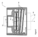
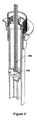
図1はバイアルの一例の等角図を示し、図1’は図1のバイアルの一例の断面図を示し、図1’’は図1のバイアルの一例の等角断面図を示す。図2は図1のバイアルの一例のキャップの詳細断面図を示す。 1 shows an isometric view of an example of a vial, FIG. 1'shows a cross-sectional view of an example of a vial of FIG. 1, and FIG. 1 ″ shows an isometric view of an example of a vial of FIG. FIG. 2 shows a detailed cross-sectional view of the cap of an example of the vial of FIG.
キャップ104と容器102とを有するバイアル100を図1―1’’に示す。バイアル100は、混合動作中にバイアル100を保持する入れ物142内に適合する寸法としてもよい。キャップ104は、一般に容器102の内部の方に向いて、キャップが固定される容器の開放端を壁で仕切るふた表面106(図2を参照)を有してもよい。キャップ104はまた、内方に面し、実質的にふた表面106と直角な方向にふた表面106から離れるように延在する側壁または側壁108を有してもよい(この場合、側壁108へのわずかなテーパがあり、ここにおける「実質的に直角」の語は±10°内の直角度であり、側壁はまた、ふた表面に対し直角な主要構成部品を有する方向148に沿ってふた表面から離れるように延在すると考えられる)。実施態様の一例では、単一の環状の側壁108がある。しかしながら、キャップ104は、ふた表面106を通り抜けて、プローブの軸またはストローの軸がキャップ104の取り外しを要さずにキャップ104を通して容器102の内部に挿入されることを可能にする開口114を有する。いくつかの実施態様では、開口114は、ホイル誘導シールまたは他の膜等の穿孔可能なシール128で封をされ、流体の潜在的な漏出または容器102内での汚染を防いでもよい。
A
キャップ104はその中でプランジャーヘッド110を保持してもよい。プランジャーヘッド110は保持構造112によってキャップ104内で保持されてもよい。この実施例では、保持構造112は内面120を有する環状の壁から成り、当該内面120はそれから径方向内方に突出する1つ以上のレッジ面122を有する。レッジ面122は、プランジャーヘッド110の最外径よりもわずかに、例えば約0.2mm〜約0.5mm小さい、最内縁124を提供し、それによってプランジャーヘッド110がキャップ104から落ちるのを防いでもよい。言いかえれば、最内縁124は、プランジャーヘッド110の最外周によって画定され、ふた表面106と垂直な方向148に沿って延在する角柱体積146内にあってもよい。しかしながら、十分な力がふた表面106に対し概ね直角な方向に沿って、容器102に向かってプランジャーヘッド110にかかると、プランジャーヘッド110は、レッジ面122を通過して容器102の中に押し込まれ得る。例えば、プランジャーヘッド110は、プランジャーヘッド110が保持構造112から出ることを可能にするため、レッジを変形させ、レッジ面122の最内径を拡大させてもよく、および/または、プランジャーヘッド110がそれ自体で縮んでプランジャーヘッド110の最外径を縮小してもよい。いくつかの実施態様では、内面120は、プランジャーヘッド110の最外周より大きい内周を画定し、それによってレッジタイプの保持構造112によって保持されている間に、プランジャーヘッド110がキャップ104の中に浮くことができるようにしてもよい。
The
プランジャーヘッド110は、軸の挿入部分であって、例えばプローブまたはストローの軸の挿入部分を受ける軸保持構造116を含んでもよい。軸保持構造116は、そこに挿入されるよう意図された軸の外周より寸法がわずかに小さく、それによって軸と軸保持構造116との間に圧入部を形成してもよい。
The
キャップ104は、摩擦/圧入接続部、バヨネットスタイル接続部、または耐タンパー性の、バーブを付けた使い捨ての接続部等の他のタイプの接続部も使用してもよいが、ねじ山構造126を使用して容器102に固定されてもよい。
The
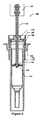
図3はサンプリングプローブによって穴をあけられた後の図1のバイアルの一例の断面図を示し、図3’は図3のバイアルの一例の等角断面図を示し、図4はサンプリングプローブがバイアルに完全に挿入された後の図3のバイアルの一例の断面図を示し、図4’は図4のバイアルの一例の等角断面図を示す。上述したように、バイアル100は混合動作のため入れ物142内に挿入されてもよい。次に、軸118を有するサンプルプローブを、例えば軸往復運動システム134によって、キャップ104内に降ろしてもよい。穿孔可能なシール128を有する実施態様では、穿孔可能なシール128を通して軸118を挿入し、それによって封を破ってもよい。そして、軸118は、例えば先端である軸の挿入部分130がプランジャーヘッド110の軸受構造116内に挿入されるように、キャップ104内にさらに挿入されてもよい。前述したように、軸受構造116は、軸118を圧入する寸法としてもよい。保持構造112は、保持構造112からプランジャーヘッド110を分離するのに要する力が、挿入部分130を軸受構造116に挿入するのに要する力よりも大きくなる寸法とすることができる。これは、プランジャーヘッド110が軸118上に圧入される前に、プランジャーヘッド110が保持構造112から突き出ないことを確実にする。軸118はまた、停止部分132、例えばすえ込み加工またはろう付されたフェルールまたはブシュ、であって、軸受構造より大きい直径の停止部分を有してもよい。停止部分132は、挿入部分130が軸受構造116に完全に挿入されるときにプランジャーヘッド110に当接してもよい。停止部分132がプランジャーヘッド110に係合すると、次に、軸118にかけられる概して全ての下向きの力はプランジャーヘッド110に移されて、プランジャーヘッド110を保持構造112から外すために使用し得る。プランジャーヘッド110が保持構造112から外れると、プランジャーヘッド110が容器102の内部144で往復運動するように、軸往復運動機構134を使用して、軸118を容器102内で上下に動かしてもよい。内部容積144内に存在する任意の流体は、したがって、プランジャーヘッド110を通過して前後に押し流され、それによって適切な混合を確実にする。4回〜7回の往復運動(上下運動)が、多くのサンプルテストケースにおいて十分な混合を提供することが分かった。
FIG. 3 shows a cross-sectional view of an example of a vial of FIG. 1 after being punctured by a sampling probe, FIG. 3'shows an equiangular cross-sectional view of an example of a vial of FIG. 3, and FIG. 4 shows a sampling probe of a vial. A cross-sectional view of an example of a vial of FIG. 3 after being completely inserted into is shown, and FIG. 4'shows an equiangular cross-sectional view of an example of the vial of FIG. As mentioned above, the
容器102の内容物が容器102の中でプランジャーヘッドを往復運動することによって完全に混合されると、軸118は、挿入部分130が容器102の底部に位置するように、延在する。容器102の底部に集まった流体は、例えばポンプまたは他の吸気を発生させる装置によって、軸118を通して引き上げられる。容器102から十分な流体が引き抜かれると、容器102から軸118を引き抜くことができる。そのような引き抜きの間、プランジャーヘッド110は保持構造112に接することができ、これはプランジャーヘッド110がさらに動くことを防ぐことができ、したがってプランジャーヘッド110を軸118から引き離し、容器102の中へ後退させる。いくつかの実施態様では、保持構造112またはその部分によって、プランジャーヘッド110が軸118から引き離れたままであるが容器102の中へと後退しないように、プランジャーヘッド110は再度捕捉されてもよい。
When the contents of the
プランジャーヘッド110は、プラスチックまたは強靭なエラストマー等の他の高分子材料から形成してもよい。これは、プランジャーヘッド110がやや追従性があることができるようにし、それが保持構造112から分離される際に屈曲および縮むことができるようにし、また、プランジャーヘッドが容易に拡張して軸118の圧入部を収容することができるようにし得る。
The
図5はキャップの別の例の断面図を示す。この図では、キャップ504の保持構造512はレッジ面を有さず、代わりに環状の壁によってプランジャーヘッド510の外径よりも内径がわずかに小さい寸法とされた内面520が設けられ、それにより、圧縮と摩擦を通じてプランジャーヘッド510を所定位置に保持する。
FIG. 5 shows a cross-sectional view of another example of the cap. In this figure, the holding structure 512 of the
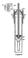
図6は統合されたプランジャーヘッドと共に、バイアルの別の例の等角切断図を示す図である。図6’は軸が挿入されて、プランジャーヘッドが展開されている状態で、図6のバイアルの一例の等角図を示す図である。図6’’は図6’のバイアルの一例の断面図を示す図である。 FIG. 6 shows an equiangular cut view of another example of a vial, along with an integrated plunger head. FIG. 6'is a diagram showing an isometric view of an example of the vial of FIG. 6 with the shaft inserted and the plunger head unfolded. FIG. 6 ″ is a diagram showing a cross-sectional view of an example of the vial of FIG. 6 ″.
図6〜図6’’では、バイアルを容器602とキャップ604と共に示す。キャップ604は、プランジャーヘッド610が保持構造612に軽く圧入される寸法とされた環状の内面を有する保持構造612によってキャップ604内に保持されるプランジャーヘッド610を有する。さらに、保持構造612は、保持構造612をさらに狭める環状リッジ654を有してもよい。この環状リッジ654は、保持構造612からプランジャーヘッド610を分離させるために、プランジャーヘッド610を単独で圧入部から分離させるのに必要な力を超えて、プランジャーヘッド610に追加の力がかかることを要する。したがって、環状リッジ654は軸618の挿入部分630の挿入の間、プランジャーヘッドを保持し、そして軸618は、軸618の停止部分632がプランジャーヘッド610における軸受構造の内部レッジ/内面に当接するときに、環状リッジ654を通過してプランジャーヘッドを押し出す。そして、プランジャーヘッド610は容器602内で往復運動する。軸618が容器602から取り除かれたときに、プランジャーヘッド610は保持構造612に再度係合してもよく、そして、いくつかの実施態様では、環状リッジ654によって保持構造612の上部656から分離した、保持構造612の下部658と再度係合してもよい。保持構造612は、したがって、軸618を引き抜くとプランジャーヘッド610を再度捕捉し得る。
6-6'' show the vial with the
この実施態様では、プランジャーヘッド610は外側周囲部の周りに複数の溝またはチャネル650を有し、混合の間、プランジャーヘッド610を通過する向上した流体流れを可能にする。
In this embodiment, the
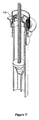
図7は統合されたプランジャーヘッドと共に、バイアルの別の例の等角切断図を示す。図7’は軸が挿入されて、プランジャーヘッドが展開されている状態で、図7のバイアルの一例の等角図を示す図である。図7と図7’において、プランジャーヘッド710がその中に溝を有さない点、および保持構造712が環状リッジを有さず、代わりにプランジャーヘッド710とのよりきつい圧入に依存する点を除き、図6から図6’’で示すバイアルとよく似たバイアルを示す。
FIG. 7 shows an equiangular cut view of another example of a vial, along with an integrated plunger head. FIG. 7'is a diagram showing an isometric view of an example of the vial of FIG. 7 with the shaft inserted and the plunger head unfolded. In FIGS. 7 and 7', the
図8は統合されたプランジャーヘッドと共にバイアルの別の例の等角切断図を示す。図8’は軸が挿入されて、プランジャーヘッドが展開されている状態で、図8のバイアルの一例の等角図を示す。図8と図8’では、プランジャーヘッド810は、プランジャーヘッド810の往復運動の間、流体がプランジャーヘッド810を通って流れることを可能にする貫通孔852のパターンを有する。キャップ804はまた、図7に示したものと同様の保持構造812を有する。その他の点では、図8と図8'とで示したバイアルは図1から図4で示したバイアルと同様である。
FIG. 8 shows an equiangular cut view of another example of a vial with an integrated plunger head. FIG. 8'shows an isometric view of an example of the vial of FIG. 8 with the shaft inserted and the plunger head unfolded. In FIGS. 8 and 8', the
本明細書および特許請求の範囲の至る所で使用される「実質的に」および「約」という用語は、例えば処理のばらつきにより、僅かな変動を記述し且つ考慮すべく使用される。本明細書において特定の文脈で明示されない限り、例えば、それらは、±2%以下の如く、±1%以下の如く、±0.5%以下の如く、±0.2%以下の如く、±0.1%以下の如く、±0.05%以下の如く、明示された値または明示された関係と同等の値の±5%以下を指し得る。例えば、「実質的に直角」とは、2つの表面間の角度が±5%(あるいは、上記に列挙した他の境界範囲のうちの1つ)以内である幾何学的関係を指すために使用され得る。 The terms "substantially" and "about" used throughout the specification and claims are used to describe and account for slight variability, for example due to processing variability. Unless expressly specified herein, they are, for example, ± 2% or less, ± 1% or less, ± 0.5% or less, ± 0.2% or less, ± It can refer to ± 5% or less of the specified value or the equivalent of the specified relationship, such as 0.1% or less, ± 0.05% or less. For example, "substantially right angle" is used to refer to a geometric relationship where the angle between two surfaces is within ± 5% (or one of the other boundary ranges listed above). Can be done.
例えば(a)、(b)、(c)・・・等の序数標識がある場合、本発明および特許請求の範囲におけるこの使用は、そのような順序またはシークェンスが明確に示される範囲を除き、いかなる特定の順序またはシークェンスも伝えるものではないと理解されるべきである。例えば、(i)、(ii)、および(iii)と明示された3つの工程がある場合、これらの工程は、別段の指示がない限り、任意の順序で(または別段禁忌でない限り、同時に)実行され得る。例えば、工程(ii)が工程(i)で作成された要素の処理を含む場合、工程(ii)は工程(i)の後のある時点で起こっていると見なされてもよい。同様に、工程(i)が工程(ii)で生成された要素の処理を含む場合、その逆が理解されるべきである。 For example, if there are ordinal indicators such as (a), (b), (c) ..., this use within the scope of the present invention and claims is to the extent that such order or sequence is clearly indicated. It should be understood that it does not convey any particular order or sequence. For example, if there are three steps specified as (i), (ii), and (iii), these steps may be in any order (or at the same time, unless otherwise contraindicated) unless otherwise indicated. Can be executed. For example, if step (ii) involves processing the elements created in step (i), step (ii) may be considered to occur at some point after step (i). Similarly, if step (i) involves processing the elements generated in step (ii), the reverse should be understood.
また、例えば「to」の使用、例えば「キャップがそれと連結する(with which the cap is to interface)」は、「キャップがそれと連結するよう構成される(with which the cap is configured to interface)」等の「〜するよう構成される(configured to)」等の用語に置き換えることができることも理解されたい。 Also, for example, the use of "to", such as "with a cap is to interface", means "with a cap is connected to interface", etc. It should also be understood that it can be replaced with terms such as "concluded to" in.
前述の概念の全ての組み合わせ(但し、このような概念が相互に矛盾しないことを条件とする)が、本明細書に開示された発明の主題の一部として企図されることを理解されたい。特に、本開示の最後に見られる、特許請求される主題の全ての組み合わせが、本明細書に開示される本発明の主題の一部として企図される。簡潔にするため、本明細書においてはこれらの置換および組み合わせの多くは、別個には説明および/または示されない。 It should be understood that all combinations of the aforementioned concepts, provided that such concepts are consistent with each other, are intended as part of the subject matter of the invention disclosed herein. In particular, all combinations of claims found at the end of this disclosure are contemplated as part of the subject matter of the invention disclosed herein. For brevity, many of these substitutions and combinations are not separately described and / or shown herein.
Claims (18)
前記キャップが連結する容器の内部に適合する寸法とされたプランジャーヘッドと、
保持構造と、
前記キャップ内の開口と、を備える装置であって、
前記プランジャーヘッドは、前記開口を通して挿入可能な軸を受ける軸受構造を含み、
前記軸受構造は、前記プランジャーヘッドを貫通する穴であり、
前記プランジャーヘッドは前記開口が前記軸受構造と並ぶように前記保持構造によって前記キャップ内に配置され、
前記保持構造は、第1の閾値より高い力が前記ふた表面から垂直に離れる方向に前記プランジャーヘッドに付与されると前記プランジャーヘッドを解放する、装置。 A cap having a lid surface and one or more side walls extending away from the lid surface along a direction having key components parallel to the lid surface normal.
A plunger head sized to fit inside the container to which the cap is connected, and
Holding structure and
A device comprising an opening in the cap.
The plunger head comprises a bearing structure that receives a shaft that can be inserted through the opening.
The bearing structure is a hole penetrating the plunger head.
The plunger head is arranged in the cap by the holding structure so that the opening is aligned with the bearing structure.
The holding structure is a device that releases the plunger head when a force higher than the first threshold value is applied to the plunger head in a direction vertically away from the surface of the lid.
前記キャップは前記容器に取り付けられ、
前記容器の前記内部は、前記プランジャーヘッドを前記容器の前記内部で前記ふた表面の前記法線と平行な方向に往復運動可能にする寸法とされている、装置。 The device according to claim 1, further comprising the container.
The cap is attached to the container and
The inside of the container is sized to allow the plunger head to reciprocate inside the container in a direction parallel to the normal of the lid surface.
前記軸は、前記軸が前記開口を通して挿入されるときに前記ふた表面の前記法線と平行となる中心軸線を有し、
前記軸は挿入部分と停止部分とを有し、
前記挿入部分は前記軸の一端から前記停止部分まで延在し、
前記停止部分は、前記中心軸線に対し直角な方向に前記挿入部分より大きい寸法とされ、また、前記中心軸線に対し直角な方向に前記軸受構造より大きい寸法とされ、
前記停止部分は、前記挿入部分が前記軸受構造に完全に挿入されるときに前記プランジャーヘッドと係合する、装置。 The device according to claim 9 , further comprising the shaft.
The axis has a central axis that is parallel to the normal of the lid surface when the axis is inserted through the opening.
The shaft has an insertion portion and a stop portion, and has an insertion portion and a stop portion.
The insertion portion extends from one end of the shaft to the stop portion.
The stop portion has a dimension larger than the insertion portion in a direction perpendicular to the central axis, and has a dimension larger than the bearing structure in a direction perpendicular to the central axis.
The stop portion is a device that engages the plunger head when the insertion portion is fully inserted into the bearing structure.
前記挿入部分が前記軸受構造に完全に挿入されるように、前記中心軸線に沿って前記開口を通して前記軸を移動し、
少なくとも前記第1の閾値の力を前記軸に付与し、
前記容器の前記内部で前記軸を1回以上往復運動させる、装置。 The device according to claim 11 , further comprising an axial reciprocating motion mechanism, wherein the axial reciprocating motion mechanism is a device.
The shaft is moved through the opening along the central axis so that the insertion portion is completely inserted into the bearing structure.
At least the force of the first threshold is applied to the axis,
A device that reciprocates the shaft one or more times inside the container.
前記軸の前記挿入部分が前記プランジャーヘッドの前記軸受構造内に完全に挿入された後に第1の閾値より大きな力を前記軸に付与し、それによって前記保持構造が前記プランジャーヘッドを解放するステップと、
前記プランジャーヘッドが前記容器の内部容積内で往復運動するように、前記プランジャーヘッドが前記保持構造から解放された後に、前記軸を往復運動するステップとを含む、方法。 A hole through which the bearing structure penetrates the plunger head, which is a step of inserting the insertion portion of the shaft into the bearing structure in the plunger head disposed in the cap by the holding structure through the opening in the cap of the container. Is a step and
After the insertion portion of the shaft is completely inserted into the bearing structure of the plunger head, a force greater than the first threshold is applied to the shaft, whereby the holding structure releases the plunger head. Steps and
A method comprising reciprocating the shaft after the plunger head has been released from the holding structure such that the plunger head reciprocates within the internal volume of the container.
外径を有すると共に前記キャップが連結する容器の内部に適合する寸法とされたプランジャーヘッドと、
保持構造と、
前記キャップ内の開口と、を備える装置であって、
前記プランジャーヘッドは、前記開口を通して挿入可能な軸を受ける軸受構造を含み、
前記軸受構造は、前記プランジャーヘッドを貫通する穴であり、
前記プランジャーヘッドは前記開口が前記軸受構造と並ぶように前記保持構造によって前記キャップ内に配置され、
前記保持構造は、第1の閾値より高い力が前記ふた表面から垂直に離れる方向に前記プランジャーヘッドに付与されると前記プランジャーヘッドを解放し、
前記プランジャーヘッドの最大寸法は、前記キャップ内の開口の最小寸法より大きい、装置。
A cap having a lid surface and one or more side walls extending away from the lid surface along a direction having key components parallel to the lid surface normal.
A plunger head having an outer diameter and sized to fit inside the container to which the cap is connected,
Holding structure and
A device comprising an opening in the cap.
The plunger head comprises a bearing structure that receives a shaft that can be inserted through the opening.
The bearing structure is a hole penetrating the plunger head.
The plunger head is arranged in the cap by the holding structure so that the opening is aligned with the bearing structure.
The holding structure releases the plunger head when a force higher than the first threshold is applied to the plunger head in a direction perpendicular to the surface of the lid.
A device in which the maximum dimension of the plunger head is greater than the minimum dimension of the opening in the cap.
Applications Claiming Priority (5)
| Application Number | Priority Date | Filing Date | Title |
|---|---|---|---|
| US201762441921P | 2017-01-03 | 2017-01-03 | |
| US62/441,921 | 2017-01-03 | ||
| US15/841,113 US10537892B2 (en) | 2017-01-03 | 2017-12-13 | Sample tube with integrated mixing plunger head |
| US15/841,113 | 2017-12-13 | ||
| PCT/US2017/067833 WO2018128840A1 (en) | 2017-01-03 | 2017-12-21 | Sample tube with integrated mixing plunger head |
Publications (3)
| Publication Number | Publication Date |
|---|---|
| JP2020504000A JP2020504000A (en) | 2020-02-06 |
| JP2020504000A5 JP2020504000A5 (en) | 2021-01-28 |
| JP6975729B2 true JP6975729B2 (en) | 2021-12-01 |
Family
ID=62709265
Family Applications (1)
| Application Number | Title | Priority Date | Filing Date |
|---|---|---|---|
| JP2018566889A Active JP6975729B2 (en) | 2017-01-03 | 2017-12-21 | Sample tube with integrated mixing plunger head |
Country Status (15)
| Country | Link |
|---|---|
| US (1) | US10537892B2 (en) |
| EP (1) | EP3565665B1 (en) |
| JP (1) | JP6975729B2 (en) |
| KR (1) | KR102582175B1 (en) |
| CN (1) | CN109328109B (en) |
| AU (1) | AU2017390255B2 (en) |
| BR (1) | BR112018075417B1 (en) |
| CA (1) | CA3023119C (en) |
| IL (1) | IL262706B (en) |
| MY (1) | MY191888A (en) |
| NZ (1) | NZ747889A (en) |
| RU (1) | RU2711190C1 (en) |
| SG (1) | SG11201811331PA (en) |
| TW (1) | TWI732081B (en) |
| WO (1) | WO2018128840A1 (en) |
Families Citing this family (4)
| Publication number | Priority date | Publication date | Assignee | Title |
|---|---|---|---|---|
| WO2017158687A1 (en) | 2016-03-14 | 2017-09-21 | 神戸バイオロボティクス株式会社 | Sample container and automatic sample container processing system |
| WO2020180535A1 (en) * | 2019-03-05 | 2020-09-10 | Thomas Jefferson University | Dual-function receptacle seal |
| KR102488945B1 (en) | 2020-07-15 | 2023-01-17 | 주식회사 앱솔로지 | Sample Pretreatment Tube |
| WO2023008457A1 (en) * | 2021-07-28 | 2023-02-02 | 公益財団法人神戸医療産業都市推進機構 | Vessel for use in centrifugal separation and method for producing separated liquid using same |
Family Cites Families (45)
| Publication number | Priority date | Publication date | Assignee | Title |
|---|---|---|---|---|
| US4479578A (en) * | 1981-04-09 | 1984-10-30 | The West Company | Single barrel two-compartment medicament container assembly |
| FI62470C (en) | 1981-06-17 | 1983-01-10 | Labsystems Oy | pipette |
| US5143211A (en) * | 1988-04-22 | 1992-09-01 | Rathor Ag | Multi-chambered container |
| GB9114265D0 (en) * | 1991-07-02 | 1991-08-21 | Amersham Int Plc | Sampling device |
| JP3074655B2 (en) * | 1991-12-06 | 2000-08-07 | 株式会社ニッショー | Prefilled syringe for two components |
| JPH0779963B2 (en) * | 1993-03-09 | 1995-08-30 | トルク精密工業株式会社 | Reaction vessel |
| DE4338553A1 (en) * | 1993-11-08 | 1995-05-18 | Ferring Arzneimittel Gmbh | Injection syringe for mixing and applying injection substances |
| DE69609919T2 (en) | 1995-10-18 | 2001-01-18 | Daikyo Seiko Ltd | Plastic cap and process for its manufacture |
| JPH09238998A (en) * | 1996-03-05 | 1997-09-16 | Daikyo Seiko:Kk | Plastic cap and its preparation |
| CA2283874C (en) | 1997-03-12 | 2006-12-12 | Fredrick Michael Coory | Discharge cap with releasable tablet basket |
| EP1495811B2 (en) * | 1999-05-14 | 2014-05-28 | Gen-Probe Incorporated | Fluid transfer device for use with penetrable cap |
| US6716396B1 (en) * | 1999-05-14 | 2004-04-06 | Gen-Probe Incorporated | Penetrable cap |
| JP3502800B2 (en) * | 1999-12-15 | 2004-03-02 | 新光電気工業株式会社 | Method for manufacturing semiconductor device |
| US7980755B2 (en) * | 2000-05-02 | 2011-07-19 | Renfro Charles K | Method for mixing additive into viscous material |
| DE10242984B4 (en) * | 2002-09-17 | 2010-09-23 | Sanatis Gmbh | Device for producing mixtures of two components |
| GB2393670A (en) * | 2002-10-02 | 2004-04-07 | Secr Defence | Burette with hollow dispensing shaft on plunger |
| AU2005312310A1 (en) * | 2004-12-03 | 2006-06-08 | Duoject Medical Systems Inc. | Cartridge, device and method for pharmaceutical storage, mixing and delivery |
| KR100738100B1 (en) * | 2006-01-19 | 2007-07-12 | 삼성전자주식회사 | Device and method for pre-treatment and injection of liquid specimen |
| US7905654B1 (en) * | 2006-11-13 | 2011-03-15 | Luis Cordero | Hand held manually operated mixer |
| WO2008083313A2 (en) | 2007-01-01 | 2008-07-10 | Medrad, Inc. | Methods and systems for integrated radiopharmaceutical generation, preparation, transportation, and administration |
| US7879002B2 (en) * | 2007-10-31 | 2011-02-01 | Ultradent Products, Inc. | Mixing device including a plunging mixing member for use with a syringe |
| US8776621B2 (en) * | 2009-03-06 | 2014-07-15 | Dionex Corporation | Fluid sample delivery system and method |
| CN102770208B (en) * | 2009-12-30 | 2016-02-03 | 3M创新有限公司 | Use the living organism load detecting that particulate carries out |
| US20140048430A1 (en) * | 2011-03-08 | 2014-02-20 | Jean-Pierre Giraud | Cap and container assembly for a dosage product |
| BR112013023055A2 (en) * | 2011-03-11 | 2016-12-13 | Qiagen Gmbh | sample container |
| US9650175B2 (en) * | 2011-08-12 | 2017-05-16 | Kuo-Cheng Wu | Container |
| MX2014004367A (en) * | 2011-10-20 | 2015-04-13 | Becton Dickinson Co | Syringe with removable plunger for arterial blood gas sample collection. |
| US20160242674A1 (en) | 2012-02-01 | 2016-08-25 | Invoy Technologies, Llc | Portable breath analyzer for multiple accurate readings |
| ITPD20120102A1 (en) * | 2012-04-02 | 2013-10-03 | Leader Medica S R L | SEPARATE ROOM CONTAINER FOR THE TREATMENT OF BIOLOGICAL FABRICS BY CENTRIFUGAL SEPARATION |
| WO2014090776A1 (en) | 2012-12-10 | 2014-06-19 | Kao Germany Gmbh | Nozzle for a two-chamber container for mixing two components and applying the mixture |
| US9159832B2 (en) * | 2013-03-08 | 2015-10-13 | Taiwan Semiconductor Manufacturing Company, Ltd. | Semiconductor fin structures and methods for forming the same |
| EP3708182A1 (en) * | 2013-03-29 | 2020-09-16 | The Regents Of The University Of Colorado | Compositions and methods for preparing a subject for organ or non-organ implantation |
| CN203473563U (en) * | 2013-06-24 | 2014-03-12 | 李和伟 | Freeze-drying excipient packaging and delivering system |
| CN105530977B (en) * | 2013-07-16 | 2019-10-11 | 尤尼特拉克特注射器公司 | The syringe of injection is mixed and conveyed for repetition |
| JP6176842B2 (en) * | 2013-07-23 | 2017-08-09 | 東芝メディカルシステムズ株式会社 | Automatic analyzer |
| CA2961223C (en) | 2013-12-12 | 2019-04-30 | Yamaha Hatsudoki Kabushiki Kaisha | A moving apparatus for moving a subject using tips |
| US9895289B2 (en) * | 2014-04-18 | 2018-02-20 | Covidien Lp | Mixing syringe |
| DK3145634T3 (en) | 2014-05-21 | 2020-09-21 | Aidian Oy | Sampling and analysis kit, sample holder and procedure |
| US20150344203A1 (en) | 2014-05-27 | 2015-12-03 | Michael R. Anderson | Single piece button actuated dispensing cap |
| WO2016009764A1 (en) * | 2014-07-18 | 2016-01-21 | 株式会社 日立ハイテクノロジーズ | Liquid stirring method |
| WO2016014406A1 (en) * | 2014-07-21 | 2016-01-28 | Ge Healthcare As | Deflectable plunger head |
| TWI551852B (en) * | 2014-08-15 | 2016-10-01 | 芮寶生醫股份有限公司 | A pretreatment device for biological specimen and method for biological specimen nucleic acids extraction |
| CN104306152A (en) * | 2014-10-10 | 2015-01-28 | 丁西 | Three-cavity clamping type medicine bottle and injection device composite member thereof |
| US10495614B2 (en) | 2014-12-30 | 2019-12-03 | Dionex Corporation | Vial cap and method for removing matrix components from a liquid sample |
| JP2016158557A (en) | 2015-03-02 | 2016-09-05 | セイコーエプソン株式会社 | Container, biological substance purification cartridge, and assembly kit for biological substance purification cartridge |
-
2017
- 2017-12-13 US US15/841,113 patent/US10537892B2/en active Active
- 2017-12-21 JP JP2018566889A patent/JP6975729B2/en active Active
- 2017-12-21 SG SG11201811331PA patent/SG11201811331PA/en unknown
- 2017-12-21 TW TW106145077A patent/TWI732081B/en active
- 2017-12-21 CN CN201780038982.5A patent/CN109328109B/en active Active
- 2017-12-21 RU RU2018145043A patent/RU2711190C1/en active
- 2017-12-21 NZ NZ747889A patent/NZ747889A/en unknown
- 2017-12-21 WO PCT/US2017/067833 patent/WO2018128840A1/en unknown
- 2017-12-21 EP EP17890539.4A patent/EP3565665B1/en active Active
- 2017-12-21 KR KR1020187037123A patent/KR102582175B1/en active IP Right Grant
- 2017-12-21 CA CA3023119A patent/CA3023119C/en active Active
- 2017-12-21 AU AU2017390255A patent/AU2017390255B2/en active Active
- 2017-12-21 MY MYPI2018002641A patent/MY191888A/en unknown
- 2017-12-21 BR BR112018075417-0A patent/BR112018075417B1/en active IP Right Grant
-
2018
- 2018-10-31 IL IL262706A patent/IL262706B/en active IP Right Grant
Also Published As
| Publication number | Publication date |
|---|---|
| TWI732081B (en) | 2021-07-01 |
| MY191888A (en) | 2022-07-18 |
| TW201829064A (en) | 2018-08-16 |
| RU2711190C1 (en) | 2020-01-15 |
| CN109328109B (en) | 2021-06-25 |
| CN109328109A (en) | 2019-02-12 |
| CA3023119C (en) | 2021-02-09 |
| NZ747889A (en) | 2020-08-28 |
| IL262706A (en) | 2018-12-31 |
| IL262706B (en) | 2020-07-30 |
| KR102582175B1 (en) | 2023-09-22 |
| WO2018128840A1 (en) | 2018-07-12 |
| US10537892B2 (en) | 2020-01-21 |
| JP2020504000A (en) | 2020-02-06 |
| BR112018075417A2 (en) | 2019-03-12 |
| AU2017390255A1 (en) | 2018-11-22 |
| SG11201811331PA (en) | 2019-01-30 |
| AU2017390255B2 (en) | 2022-01-20 |
| CA3023119A1 (en) | 2018-07-12 |
| US20180185840A1 (en) | 2018-07-05 |
| EP3565665A4 (en) | 2020-09-09 |
| EP3565665A1 (en) | 2019-11-13 |
| BR112018075417B1 (en) | 2023-03-07 |
| KR20190095111A (en) | 2019-08-14 |
| EP3565665B1 (en) | 2022-07-27 |
Similar Documents
| Publication | Publication Date | Title |
|---|---|---|
| JP6975729B2 (en) | Sample tube with integrated mixing plunger head | |
| JP6637935B2 (en) | Tubular plunger assembly and filter vial kit | |
| US10568809B2 (en) | Liquid-transfer adapter beveled spike | |
| JP5827345B2 (en) | Universal closure device | |
| US10512908B2 (en) | Method for preparing a sample | |
| US10974248B2 (en) | Adapter for laboratory cell strainer | |
| CN113631270B (en) | Sample container for sample pretreatment | |
| EP4169615A1 (en) | Sample tube, sample tube closing device and method for closing a sample tube | |
| US20230398547A1 (en) | Microplate system and containment | |
| US11319122B2 (en) | Container stopper for high pierce count applications | |
| EP4279181A1 (en) | Device for sealing of a reagent container | |
| WO2023019237A2 (en) | Devices and methods for sample collection |
Legal Events
| Date | Code | Title | Description |
|---|---|---|---|
| A521 | Request for written amendment filed |
Free format text: JAPANESE INTERMEDIATE CODE: A523 Effective date: 20201204 |
|
| A621 | Written request for application examination |
Free format text: JAPANESE INTERMEDIATE CODE: A621 Effective date: 20201204 |
|
| A871 | Explanation of circumstances concerning accelerated examination |
Free format text: JAPANESE INTERMEDIATE CODE: A871 Effective date: 20201204 |
|
| A975 | Report on accelerated examination |
Free format text: JAPANESE INTERMEDIATE CODE: A971005 Effective date: 20210203 |
|
| A131 | Notification of reasons for refusal |
Free format text: JAPANESE INTERMEDIATE CODE: A131 Effective date: 20210209 |
|
| A521 | Request for written amendment filed |
Free format text: JAPANESE INTERMEDIATE CODE: A523 Effective date: 20210311 |
|
| A02 | Decision of refusal |
Free format text: JAPANESE INTERMEDIATE CODE: A02 Effective date: 20210427 |
|
| A521 | Request for written amendment filed |
Free format text: JAPANESE INTERMEDIATE CODE: A523 Effective date: 20210823 |
|
| C60 | Trial request (containing other claim documents, opposition documents) |
Free format text: JAPANESE INTERMEDIATE CODE: C60 Effective date: 20210823 |
|
| A911 | Transfer to examiner for re-examination before appeal (zenchi) |
Free format text: JAPANESE INTERMEDIATE CODE: A911 Effective date: 20210902 |
|
| C21 | Notice of transfer of a case for reconsideration by examiners before appeal proceedings |
Free format text: JAPANESE INTERMEDIATE CODE: C21 Effective date: 20210907 |
|
| TRDD | Decision of grant or rejection written | ||
| A01 | Written decision to grant a patent or to grant a registration (utility model) |
Free format text: JAPANESE INTERMEDIATE CODE: A01 Effective date: 20211102 |
|
| A61 | First payment of annual fees (during grant procedure) |
Free format text: JAPANESE INTERMEDIATE CODE: A61 Effective date: 20211108 |
|
| R150 | Certificate of patent or registration of utility model |
Ref document number: 6975729 Country of ref document: JP Free format text: JAPANESE INTERMEDIATE CODE: R150 |