JP6974875B2 - Pipe wrench - Google Patents
Pipe wrench Download PDFInfo
- Publication number
- JP6974875B2 JP6974875B2 JP2020002792A JP2020002792A JP6974875B2 JP 6974875 B2 JP6974875 B2 JP 6974875B2 JP 2020002792 A JP2020002792 A JP 2020002792A JP 2020002792 A JP2020002792 A JP 2020002792A JP 6974875 B2 JP6974875 B2 JP 6974875B2
- Authority
- JP
- Japan
- Prior art keywords
- pivot pin
- guide groove
- pipe wrench
- toothed guide
- connecting member
- Prior art date
- Legal status (The legal status is an assumption and is not a legal conclusion. Google has not performed a legal analysis and makes no representation as to the accuracy of the status listed.)
- Active
Links
Images


Classifications
-
- B—PERFORMING OPERATIONS; TRANSPORTING
- B25—HAND TOOLS; PORTABLE POWER-DRIVEN TOOLS; MANIPULATORS
- B25B—TOOLS OR BENCH DEVICES NOT OTHERWISE PROVIDED FOR, FOR FASTENING, CONNECTING, DISENGAGING OR HOLDING
- B25B13/00—Spanners; Wrenches
- B25B13/48—Spanners; Wrenches for special purposes
- B25B13/50—Spanners; Wrenches for special purposes for operating on work of special profile, e.g. pipes
- B25B13/5008—Spanners; Wrenches for special purposes for operating on work of special profile, e.g. pipes for operating on pipes or cylindrical objects
- B25B13/5016—Spanners; Wrenches for special purposes for operating on work of special profile, e.g. pipes for operating on pipes or cylindrical objects by externally gripping the pipe
- B25B13/5025—Spanners; Wrenches for special purposes for operating on work of special profile, e.g. pipes for operating on pipes or cylindrical objects by externally gripping the pipe using a pipe wrench type tool
Landscapes
- Engineering & Computer Science (AREA)
- Mechanical Engineering (AREA)
- Gripping Jigs, Holding Jigs, And Positioning Jigs (AREA)
- Details Of Spanners, Wrenches, And Screw Drivers And Accessories (AREA)
- Clamps And Clips (AREA)
Description
本発明は、パイプレンチに関するものである。 The present invention relates to a pipe wrench.
一般的なパイプレンチは、互いに枢着する、第1クランプ本体と、第2クランプ本体と、を備える。前記第1クランプ本体にスライド溝が設けられている。スライド溝内に枢着ピンが設けられている。前記第2クランプ本体が前記枢着ピンに枢着されていることにより、前記第2クランプ本体は、前記第1クランプ本体に対してスライドし、又は旋回することができる。前記クランプ本体の第1歯部は、常時前記枢着ピンの第2歯部と噛み合う。前記枢着ピンを押圧することにより、前記第1歯部が第2歯部から離脱して、前記枢着ピンと前記第1クランプ本体とは、前記第1クランプ本体に対してスライドすることができる。これにより、前記第1クランプ本体の固定な第1挟み部と前記第2クランプ本体の自在な第2挟み部との間の距離を調整することができる。調整した後、前記第2クランプ本体を旋回して、自在な前記第2挟み部は、固定な前記第1挟み部へ旋回して、水管の四角形または六角形のジョイントを挟むことが可能である。中国CN204843895号に開示したパイプレンチは、以上のようなものである。
また、第1クランプ本体と第2クランプ本体とパイプレンチ全体との噛合いの密着度を改善するために、枢着ピンの底部には、枢着ピンに弾性的に押し付ける弾性部材が設けられている。これにより、枢着ピンの第2歯部とクランプ本体の第1歯部との噛合いを確保することができる。例えばCN106103000号、US2557296号、US4269089号、US2017/0066112号などは、以上のようなものである。
A general pipe wrench includes a first clamp body and a second clamp body that are pivotally attached to each other. A slide groove is provided in the first clamp body. A pivot pin is provided in the slide groove. Since the second clamp body is pivotally attached to the pivot pin, the second clamp body can slide or rotate with respect to the first clamp body. The first tooth portion of the clamp body always meshes with the second tooth portion of the pivot pin. By pressing the pivot pin, the first tooth portion is separated from the second tooth portion, and the pivot pin and the first clamp body can slide with respect to the first clamp body. .. Thereby, the distance between the fixed first sandwiched portion of the first clamp body and the free second clamped portion of the second clamp body can be adjusted. After the adjustment, the second clamp body can be swiveled so that the free second pinch can swivel to the fixed first pinch to clamp the quadrangular or hexagonal joint of the water pipe. .. The pipe wrench disclosed in China CN204843895 is as described above.
Further, in order to improve the degree of adhesion between the first clamp main body, the second clamp main body and the entire pipe wrench, an elastic member elastically pressed against the pivot pin is provided at the bottom of the pivot pin. There is. Thereby, the meshing between the second tooth portion of the pivot pin and the first tooth portion of the clamp body can be ensured. For example, CN1061033000, US2557296, US4269089, US2017 / 0066112, etc. are as described above.
しかし、このような従来のパイプレンチには、下記のような欠点がある。
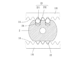
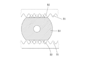
平常時に、第1歯部は第2歯部と噛み合うが、前記枢着ピンの軸方向に沿って前記枢着ピンを押圧すると、前記第1歯部は前記第2歯部から容易に離脱することができ、前記枢着ピンと前記第1クランプ本体とは前記第1クランプ本体に対してスライドすることができるが、前記枢着ピンをリリースするときに、図14に示すように、前記第1歯部B1と前記第2歯部B2とは、相対的に水平に移動した後、歯の距離および形状により、前記第1歯部の歯峰と前記第2歯部の歯元とは、枢着ピンB3の軸方向に沿って互いに係合することができず、前記枢着ピンの第2歯部は、第1歯部と容易に噛み合うことができない。これにより、前記枢着ピンはロック位置に位置決めることができず、前記枢着ピンと前記第1クランプ本体とは、前記第1クランプ本体に対してスライドする可能性がある。このとき、ユーザーは、前記枢着ピンと前記第1クランプ本体との相対位置を手動で微調整することが必要である。このため、従来のパイプレンチの使用性は良くない。
However, such a conventional pipe wrench has the following drawbacks.
In normal times, the first tooth portion meshes with the second tooth portion, but when the pivot pin is pressed along the axial direction of the pivot pin, the first tooth portion is easily separated from the second tooth portion. The pivot pin and the first clamp body can slide with respect to the first clamp body, but when the pivot pin is released, as shown in FIG. 14, the first clamp body can be slid. After the tooth portion B1 and the second tooth portion B2 move relatively horizontally, the tooth peak of the first tooth portion and the tooth root of the second tooth portion are pivotally located depending on the distance and shape of the teeth. The attachment pins B3 cannot be engaged with each other along the axial direction, and the second tooth portion of the pivot pin cannot be easily meshed with the first tooth portion. As a result, the pivot pin cannot be positioned at the locked position, and the pivot pin and the first clamp main body may slide with respect to the first clamp main body. At this time, the user needs to manually fine-tune the relative position between the pivot pin and the first clamp main body. Therefore, the usability of the conventional pipe wrench is not good.
本発明の主な目的は、枢着ピンをリリースするときに、第1クランプ本体の歯付きガイド溝を、枢着ピンの規制歯部に容易に位置合わせることができるため、枢着ピンを迅速に位置合わせることができ、歯付きガイド溝が規制歯部と容易に噛み合うことができ、ロック位置またはリリース位置に、枢着ピンを迅速に切り替えることができ、作業効率を有効に向上することが可能なパイプレンチを提供することにある。 A main object of the present invention is to quickly align the toothed guide groove of the first clamp body with the restricting tooth portion of the pivot pin when the pivot pin is released. The toothed guide groove can be easily engaged with the regulated tooth part, and the pivot pin can be quickly switched to the lock position or the release position, which can effectively improve the work efficiency. It is to provide a possible pipe wrench.
本発明に係るパイプレンチは、第1ハンドル部と、第1挟み部と、第1ハンドル部と第1挟み部との間に連接されている身部と、を備え、身部に歯付きガイド溝が少なくとも一つ設けられている第1クランプ本体と、位置が規制可能なように、歯付きガイド溝にスライド可能に設けられており、軸方向に沿ってロック位置とリリース位置の間にスライド可能であり、少なくとも一つの規制歯部と少なくとも一つの弾性付き押付部材とが設けられており、各弾性付き押付部材は、軸方向に沿って規制歯部に対応する枢着ピンと、第2ハンドル部と、枢着穴と、第2挟み部と、を備え、枢着ピンは枢着穴を挿通し、第1クランプ本体に対してスライドし、又は旋回することにより、第1挟み部は第2挟み部に対して移動する第2クランプ本体と、を備えるパイプレンチにおいて、枢着ピンがロック位置に位置するときには、規制歯部が歯付きガイド溝と噛み合い、弾性付き押付部材が歯付きガイド溝と係合せず、枢着ピンがリリース位置に移動すると、規制歯部は歯付きガイド溝から離脱し、弾性付き押付部材が離脱可能に歯付きガイド溝の歯同士の隙間と係合することを特徴とする。 The pipe wrench according to the present invention includes a first handle portion, a first pinching portion, and a body portion connected between the first handle portion and the first pinching portion, and a toothed guide is provided on the body portion. The first clamp body is provided with at least one groove, and the toothed guide groove is provided so as to be slidable so that the position can be regulated, and slides between the lock position and the release position along the axial direction. It is possible, and at least one regulating tooth portion and at least one elastic pressing member are provided, and each elastic pressing member has a pivot pin corresponding to the restricting tooth portion along the axial direction and a second handle. The first pinching portion is provided with a portion, a pivoting hole, and a second pinching portion, and the pivoting pin inserts the pivoting hole and slides or turns with respect to the first clamp body, so that the first pinching portion is the first. 2 In a pipe wrench provided with a second clamp body that moves with respect to the pinching portion, when the pivot pin is located at the locked position, the restricting tooth portion meshes with the toothed guide groove, and the elastic pressing member is a toothed guide. When the pivot pin moves to the release position without engaging with the groove, the restricting tooth part disengages from the toothed guide groove, and the elastic pressing member engages with the gap between the teeth of the toothed guide groove so that it can disengage. It is characterized by.
本発明に係るパイプレンチは、弾性付き押付部材は、係合部材と、第2弾性部材と、を備え、枢着ピンに収容穴が少なくとも一つ設けられており、弾性付き押付部材の係合部材と第2弾性部材とは、収容穴に収容されることを特徴とする。 In the pipe wrench according to the present invention, the elastic pressing member includes an engaging member and a second elastic member, and the pivot pin is provided with at least one accommodating hole, and the elastic pressing member is engaged. The member and the second elastic member are characterized in that they are accommodated in the accommodating holes.
本発明に係るパイプレンチは、第2弾性部材により、係合部材は収容穴の外側へ付勢され、係合部材はボールであり、収容穴の穴径は、ボールの直径よりやや大きく、かしめにより、ボールは収容穴の表面から脱落することはないことを特徴とする。 In the pipe wrench according to the present invention, the engaging member is urged to the outside of the accommodating hole by the second elastic member, the engaging member is a ball, and the hole diameter of the accommodating hole is slightly larger than the diameter of the ball and is crimped. Therefore, the ball does not fall off from the surface of the accommodating hole.
本発明に係るパイプレンチは、枢着ピンは、第1連接部材と、第2連接部材と、を備え、第1連接部材にロッドが連接されており、ロッドは第2クランプ本体の枢着穴を挿通し、第2連接部材はロッドの一端に当接し、第1弾性部材はロッドに嵌め設けられていることを特徴とする。 In the pipe wrench according to the present invention, the pivoting pin includes a first connecting member and a second connecting member, and a rod is connected to the first connecting member, and the rod is a pivoting hole of the second clamp body. The second articulated member is in contact with one end of the rod, and the first elastic member is fitted and provided on the rod.
本発明に係るパイプレンチは、第1連接部材の前記第2連接部材から離れた一端に径方向に突出する第1ヘッド部が設けられており、第2連接部材の前記第1連接部材から離れた一端に径方向に突出する第2ヘッド部が設けられており、第1ヘッド部と第2ヘッド部との直径は歯付きガイド溝の幅より大きいことを特徴とする。 The pipe wrench according to the present invention is provided with a first head portion that protrudes in the radial direction at one end of the first connecting member away from the second connecting member, and is separated from the first connecting member of the second connecting member. A second head portion protruding in the radial direction is provided at one end thereof, and the diameter of the first head portion and the second head portion is larger than the width of the toothed guide groove.
本発明に係るパイプレンチは、ロッドの第1ヘッド部から遠く離れた一端に、直径がより小さい凸部が設けられており、凸部は第2連接部材の穿孔に差し込まれており、ロック部材は、穿孔の第1連接部材から遠く離れた一側から、凸部に螺着されており、ロック部材の最大の径方向の寸法は、穿孔の径方向の寸法より大きく、ロッドの径方向の両側には、係合凹みがそれぞれ設けられており、第2連接部材の第1連接部材に向く一側に窪みが設けられており、ロッドは窪みに差し込まれており、窪みは穿孔と連通し、窪みの内周壁に係合突起が二つ設けられており、二つの係合突起は、それぞれ二つの係合凹みと係合することを特徴とする。 The pipe wrench according to the present invention is provided with a convex portion having a smaller diameter at one end far away from the first head portion of the rod, and the convex portion is inserted into the perforation of the second connecting member and is a lock member. Is screwed onto the convex portion from one side far away from the first articulating member of the perforation, and the maximum radial dimension of the locking member is greater than the radial dimension of the perforation and is radial of the rod. Engagement recesses are provided on both sides, a recess is provided on one side of the second articulating member facing the first articulating member, the rod is inserted into the recess, and the recess communicates with the perforation. The inner peripheral wall of the recess is provided with two engaging protrusions, each of which engages with two engaging recesses.
本発明に係るパイプレンチは、各規制歯部の軸方向に沿う一側に斜面段が設けられており、枢着ピンがリリース位置に移動すると、規制歯部の斜面段は、それに対応する歯付きガイド溝に向くことを特徴とする。 The pipe wrench according to the present invention is provided with a slope step on one side along the axial direction of each regulated tooth portion, and when the pivot pin moves to the release position, the slope step of the regulated tooth portion has a corresponding tooth. It is characterized by facing the attached guide groove.
本発明に係るパイプレンチは、規制歯部とそれに対応する弾性付き押付部材との軸方向に沿う最小距離を第1長さとし、歯付きガイド溝の軸方向に沿う厚さを第2長さとする場合には、第2長さが第1長さより大きいことを特徴とする。 In the pipe wrench according to the present invention, the minimum distance along the axial direction between the regulated tooth portion and the corresponding elastic pressing member is defined as the first length, and the thickness along the axial direction of the toothed guide groove is defined as the second length. In some cases, the second length is larger than the first length.
本発明に係るパイプレンチは、第1連接部材の底縁と、それに対向する歯付きガイド溝の外縁との間の軸方向に沿う距離を第3長さとする場合には、第3長さが第2長さより大きいことを特徴とする。 The pipe wrench according to the present invention has a third length when the distance along the axial direction between the bottom edge of the first connecting member and the outer edge of the toothed guide groove facing the bottom edge is the third length. It is characterized by being larger than the second length.
本発明に係るパイプレンチは、第2クランプ本体に仕切板が二つ設けられており、枢着穴は二つの仕切板に設けられており、第1クランプ本体は二つの仕切板の間に設けられており、枢着ピンは二つの仕切板の枢着穴を挿通することを特徴とする。 In the pipe wrench according to the present invention, the second clamp main body is provided with two partition plates, the pivot hole is provided in the two partition plates, and the first clamp main body is provided between the two partition plates. The wrench pin is characterized by inserting the pivot holes of the two dividers.
本発明に係るパイプレンチは、身部は、互いに対向する二つの側板を備え、前記二つの側板に歯付きガイド溝がそれぞれ設けられており、二つの側板の間に収容空間が形成され、二つの側板の互いに対向する側面にスライド溝がそれぞれ設けられており、二つのスライド溝は、二つの歯付きガイド溝に平行でありながら重ならず、第2クランプ本体は、駆動ハンドルと、挟み部材と、を備え、駆動ハンドルと第1クランプ本体とは、枢着ピンに枢着されており、駆動ハンドルは、一端に第2ハンドル部が設けられており、他端に突起が設けられており、駆動ハンドルに枢着穴が設けられており、枢着ピンは枢着穴を挿通し、挟み部材は、互いに連接する、第2挟み部と、スライドブロックと、を備え、スライドブロックは二つのスライド溝をスライドし、挟み部材に凹部が設けられており、突起は凹部内に当接し、駆動ハンドルが第1クランプ本体に対してスライドし、又は旋回することにより、突起は、挟み部材の第1クランプ本体に対するスライドをコントロールすることが可能であることを特徴とする。 In the pipe wrench according to the present invention, the body portion is provided with two side plates facing each other, each of the two side plates is provided with a toothed guide groove, and a storage space is formed between the two side plates. Slide grooves are provided on the opposite side surfaces of the side plates, and the two slide grooves are parallel to the two toothed guide grooves but do not overlap, and the second clamp body has a drive handle and a pinching member. , The drive handle and the first clamp body are pivotally attached to a pivot pin, and the drive handle is provided with a second handle portion at one end and a protrusion at the other end. The drive handle is provided with a pivot hole, the pivot pin inserts the pivot hole, and the clamp members are provided with a second clamp and a slide block that are connected to each other, and the slide block has two slides. The groove is slid, and a recess is provided in the sandwiching member. The protrusion abuts in the recess, and the drive handle slides or turns with respect to the first clamp body, so that the protrusion is the first of the sandwiching members. It is characterized in that it is possible to control the slide with respect to the clamp body.
本発明に係るパイプレンチは、枢着ピンには、更に、第1弾性部材が設けられており、第1弾性部材は、駆動ハンドルと枢着ピンとの間に設けられており、両方に弾性的に押し付けて、枢着ピンがロック位置へ付勢されることを特徴とする。 In the pipe wrench according to the present invention, the pivot pin is further provided with a first elastic member, and the first elastic member is provided between the drive handle and the pivot pin, and is elastic in both. It is characterized in that the pivot pin is urged to the locked position by pressing against.
本発明に係るパイプレンチは、弾性付き押付部材の中心は、規制歯部の何れかの歯の中心と同じであることを特徴とする。 The pipe wrench according to the present invention is characterized in that the center of the elastic pressing member is the same as the center of any tooth of the regulated tooth portion.
本発明に係るパイプレンチは、枢着ピンをリリースするときに、第1クランプ本体の歯付きガイド溝を、枢着ピンの規制歯部に容易に位置合わせることができるため、枢着ピンを迅速に位置合わせることができ、歯付きガイド溝が規制歯部と容易に噛み合うことができ、ロック位置またはリリース位置に、枢着ピンを迅速に切り替えることができ、作業効率を有効に向上することが可能であるという効果を有する。 The pipe wrench according to the present invention can easily align the toothed guide groove of the first clamp body with the restricting tooth portion of the pivot pin when the pivot pin is released, so that the pivot pin can be quickly aligned. It can be aligned to, the toothed guide groove can be easily engaged with the regulated tooth part, and the pivot pin can be quickly switched to the lock position or release position, which can effectively improve work efficiency. It has the effect of being possible.
以下、本発明の実施の形態を図面に基づいて説明する。 Hereinafter, embodiments of the present invention will be described with reference to the drawings.
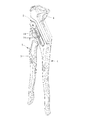
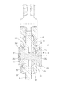
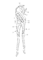
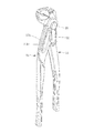
図1から図11を参照する。本発明の一実施形態に係るパイプレンチは、第1クランプ本体1と、枢着ピン2と、第2クランプ本体5と、を備える。
1 to 11 will be referred to. The pipe wrench according to the embodiment of the present invention includes a first clamp main body 1, a
第1クランプ本体1は、第1ハンドル部11と、第1挟み部12と、第1ハンドル部11と第1挟み部12との間に連接されている身部13と、を備える。身部13に歯付きガイド溝14が少なくとも一つ設けられている。
The first clamp main body 1 includes a
枢着ピン2は、位置が規制可能なように、歯付きガイド溝14にスライド可能に設けられており、軸方向に沿ってロック位置とリリース位置の間にスライド可能であり、少なくとも一つの規制歯部22と少なくとも一つの弾性付き押付部材23とが設けられている。各弾性付き押付部材23は、前記軸方向に沿って22規制歯部に対応する。
The
第2クランプ本体5は、第2ハンドル部31と、枢着穴33と、第2挟み部41と、を備える。枢着ピン2は枢着穴33を挿通する。第2クランプ本体5は、第1クランプ本体1に対してスライドし、又は旋回することにより、第1挟み部12は第2挟み部41に対して移動する。
The second clamp
枢着ピン2が前記ロック位置に位置するときには、図5に示すように、規制歯部22が歯付きガイド溝14と噛み合い、弾性付き押付部材23の係合部材231が歯付きガイド溝14と係合せず、枢着ピン2と第2クランプ本体5とは、歯付きガイド溝14に対してスライドすることができない。枢着ピン2が前記リリース位置に移動すると、図6及び図7に示すように、規制歯部22は歯付きガイド溝14から離脱し、弾性付き押付部材23が離脱して歯付きガイド溝14の歯同士の隙間と係合する。詳細には、枢着ピン2を少し押圧すると、弾性付き押付部材23が歯付きガイド溝14の歯同士の隙間に入る。枢着ピン2を底まで押圧して完全にリリースされた位置に位置するときに、規制歯部22は、歯付きガイド溝14から離脱して、歯付きガイド溝14に沿って枢着ピン2を移動することができ、これにより、パイプレンチの開口の開きの大きさを変更することができる。このとき、弾性付き押付部材2は、繰り返して押さえられて戻しても、何時も歯付きガイド溝14の歯同士の隙間と係合する。枢着ピン2をリリースすると、弾性付き押付部材23によるガイドにより、規制歯部22と歯付きガイド溝14とが容易に噛み合い、何れかの位置に位置しても、容易に戻して再度ロックすることができる。そして、枢着ピン2が歯付きガイド溝14をスライドして何れかの位置に位置するときに、弾性付き押付部材23は、歯付きガイド溝14の歯峰に近接する部位に押さえられて退行し、第1歯部の歯元に近接する箇所で、戻されて歯付きガイド溝の歯同士の隙間に直接に進入し、上記の動作が繰り返して行われる。
図10及び図11に示すように、弾性付き押付部材23が歯付きガイド溝14で前進または退行を行うことができることにより、枢着ピン2と第2クランプ本体5とは、歯付きガイド溝14の延び方向に沿ってスライドすることができる。これにより、第2クランプ本体5と第1クランプ本体1との相対位置を迅速に調整することができる。そして、弾性付き押付部材23は 歯付きガイド溝14の歯同士の隙間と係合することができ、指で枢着ピン2をリリースすると、ロック状態に戻して、弾性付き押付部材23は、歯付きガイド溝14の歯峰に垂直する点に位置するとき以外、自動的にガイドされて歯付きガイド溝14の歯同士の隙間に入る。
弾性付き押付部材23の中心は、規制歯部22の何れかの歯の中心と同じである。これにより、規制歯部22と歯付きガイド溝14とは、容易に噛み合ってロックすることができるため、枢着ピン2を前記ロック位置に位置合わせようとするときに、規制歯部22と歯付きガイド溝14とを迅速で容易に位置合わせして噛み合うことができる。このため、規制歯部22と歯付きガイド溝14とは、前記軸方向に沿って両方の歯面が互いに係合することにより、枢着ピン2が前記ロック位置に位置合わせることができないことを防止することが可能である。本発明によれば、歯付きガイド溝14と規制歯部22とが容易に噛み合うことができるため、前記ロック位置または前記リリース位置に枢着ピン2を迅速に切り替えることができ、作業効率を有効に向上することができる。
When the
As shown in FIGS. 10 and 11, the elastic pressing
The center of the elastic pressing
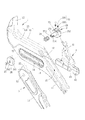
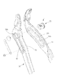
具体的には、本実施形態に係る身部13は、互いに対向する二つの側板131を備える。二つの側板131に歯付きガイド溝14がそれぞれ設けられている。二つの側板131の間に収容空間15が形成される。二つの側板131の互いに対向する側面に、スライド溝16がそれぞれ設けられている。二つのスライド溝16は、二つの歯付きガイド溝14に平行でありながら重ならない。
第2クランプ本体5は、駆動ハンドル3と、挟み部材4と、を備える。駆動ハンドル3と第1クランプ本体1とは、枢着ピン2に枢着されている。駆動ハンドル3は、一端に第2ハンドル部31が設けられており、他端に突起32が設けられている。駆動ハンドル3に枢着穴33が設けられている。挟み部材4は、互いに連接する、第2挟み部41と、スライドブロック42と、を備える。スライドブロック42は、二つのスライド溝16にスライド可能に設けられている。挟み部材4に凹部43が設けられている。突起32は凹部43内に差し込む。駆動ハンドル3が第1クランプ本体1に対してスライドし、又は旋回することにより、突起32は、挟み部材4の第1クランプ本体1に対するスライドをコントロールすることができる。これにより、第1挟み部12と第2挟み部41とにより、チューブを容易に挟むことができる。
本実施形態に係る挟み部材4のスライドブロック42は、矩形の断面形状を呈し、コ字形を呈する溝である二つのスライド溝16に合うことができる。凹部43はスライドブロック42に設けられている。もちろん、例えば、スライドブロック42は円形の断面形状を呈し、二つのスライド溝16は円弧形の断面形状を呈してもよい。本実施形態に係る枢着ピン2には、更に、第1弾性部材24が設けられている。第1弾性部材24は、駆動ハンドル3と枢着ピン2との間に設けられており、両方に弾性的に押し付けることにより、枢着ピン2が前記ロック位置へ付勢される。これにより、枢着ピン2は、外力を受けていないときに、前記ロック位置に自動的に位置合わせることができる。
Specifically, the
The second clamp
The
各弾性付き押付部材23は、係合部材231と、第2弾性部材232と、を備える。枢着ピン2に収容穴28が少なくとも一つ設けられている。各弾性付き押付部材23の係合部材231と第2弾性部材232とは、収容穴28に収容される。第2弾性部材232により、係合部材231が収容穴28の外側へ付勢される。本実施形態に係る係合部材231は、ボールであるため、歯付きガイド溝14を容易に越えることができる。収容穴28の穴径は、前記ボールの直径よりやや大きい。かしめを採用することにより、前記ボールは収容穴28の表面から脱落することを防止することができる。
Each elastic pressing
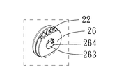
枢着ピン2は、第1連接部材25と、第2連接部材26と、を備えることが好ましい。第1連接部材25には、それと連接するロッド251が設けられている。ロッド251は第2クランプ本体5の枢着穴33を挿通する。第2連接部材26は、ロッド251の一端に当接する。第1弾性部材24は、ロッド251に嵌め設けられている。特に、本実施形態では、第1連接部材25と第2連接部材26とは、複数の規制歯部22がそれぞれ設けられている。本実施形態に係る弾性付き押付部材23と収容穴28との数量は二つある。二つの弾性付き押付部材23と二つの収容穴28とは、第1連接部材25に設けられている。もちろん、規制歯部22、弾性付き押付部材23及び収容穴28の数量は、上記の数量以外でもよく、本発明はこれに限定されない。
The
一方、第1連接部材25の前記第2連接部材から離れた一端に径方向に突出する第1ヘッド部252が設けられており、第2連接部材26の前記第1連接部材から離れた一端に径方向に突出する第2ヘッド部261が設けられている。第1ヘッド部252と第2ヘッド部261との径方向の寸法は、歯付きガイド溝14の幅より大きい。これにより、第1連接部材25と第2連接部材26とは、二つの側板131から離脱不能となる。
On the other hand, a
ロッド251の第1ヘッド部252から遠く離れた一端には、更に、直径がより小さい凸部253が設けられていることが好ましい。凸部253は、第2連接部材26の穿孔262に差し込む。ロック部材27は、穿孔262の第1連接部材25から遠く離れた側から、凸部253と螺合する。ロック部材27の最大の径方向の寸法は、穿孔262の径方向の寸法より大きい。これにより、第1連接部材25と第2連接部材26とは、容易に互いに固定することができ、互いに離脱することはない。ロッド251の径方向の両側には、係合凹み254がそれぞれ設けられている。
第2連接部材26の第1連接部材25に向く一側に窪み263が設けられている。ロッド251は窪み263に差し込む。窪み263は穿孔262と連通する。窪み263の内周壁に係合突起264が二つ設けられている。二つの係合突起264は、二つの係合凹み254とそれぞれ係合することにより、第1連接部材25と第2連接部材26とが互いに回動することを防止することができる。
It is preferable that a
A recess 263 is provided on one side of the second connecting
特に、本実施形態に係る各規制歯部22は、前記軸方向に沿う一側に斜面段221が設けられている。枢着ピン2が前記リリース位置に移動すると、規制歯部22の斜面段221は、それに対応する歯付きガイド溝14に向く。詳細には、枢着ピン2が前記リリース位置から前記ロック位置に移動しようとするときに、規制歯部22が歯付きガイド溝14に精確に位置合わせず、互いに噛み合うことができない場合には、図5から図7に示すように、各規制歯部22の斜面段221が、それに対応する歯付きガイド溝14に向くため、斜面段221が先に歯付きガイド溝14に滑り込むことにより、規制歯部22は、歯付きガイド溝14と容易に噛み合うことができ、枢着ピン2は、前記ロック位置に容易に位置合わせることができる。このため、二つの規制歯部22の斜面段221により、枢着ピン2は、前記リリース位置から前記ロック位置に容易に移動することができ、使用性が良い。
In particular, each of the
本実施形態に係る規制歯部22とそれに対応する弾性付き押付部材23との間の前記軸方向に沿う最小距離を第1長さL1とし、歯付きガイド溝14の前記軸方向に沿う厚さを第2長さL2とする場合には、図5に示すように、第2長さL2は第1長さL1より大きいことが好ましい。これにより、規制歯部22が歯付きガイド溝14から離脱していないときに、弾性付き押付部材23は歯付きガイド溝14内に進入する。このため、枢着ピン2の前記ロック位置または前記リリース位置への切替えは円滑となる。
本実施形態に係る第1連接部材25の底縁と、それに対向する歯付きガイド溝14の外縁との間の前記軸方向に沿う距離を第3長さL3とする場合に、図5及び図5Aに示すように、第3長さL3は第2長さL2より大きい。これにより、図7に示すように、枢着ピン2は前記リリース位置に完全に移動することを確保することができる。
The minimum distance along the axial direction between the
5 and FIGS. 5 and 3 when the distance along the axial direction between the bottom edge of the first connecting
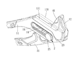
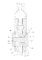
図12及び図13を参照する。本発明の別の実施形態では、第1クランプ本体1Aの身部13Aに、二つの側板131が設けられておらず、歯付きガイド溝14Aだけが設けられている。第2クランプ本体5Aに仕切板51が二つ設けられている。枢着穴33Aは二つの仕切板51に設けられている。第1クランプ本体1Aは、二つの仕切板51の間に差し込む。枢着ピン2Aは、二つの仕切板51の枢着穴33Aを挿通する。これにより、本実施形態の構造はより簡素であるが、第2クランプ本体5Aと第1クランプ本体1Aとの相対位置を迅速に調整することができ、枢着ピン2Aの前記ロック位置または前記リリース位置への切替を迅速を行うことができ、作業効率を有効に向上することができる。その他の構造は、上記の実施形態と同じなため、説明を省略した。
See FIGS. 12 and 13. In another embodiment of the present invention, the
本発明に係るパイプレンチによれば、枢着ピンを前記ロック位置に位置合わせようとするときに、弾性付き押付部材が、弾性的に移動して歯付きガイド溝の歯同士の隙間と係合することができ、これにより、枢着ピンを円滑に位置合わせることができ、規制歯部と歯付きガイド溝とは、迅速で容易に位置合わせして互いに噛み合うことができる。このため、規制歯部と歯付きガイド溝とは、前記軸方向に沿って両方の歯面が互いに係合することにより、枢着ピンが前記ロック位置に位置合わせることができないことを防止することが可能である。
本発明によれば、歯付きガイド溝と規制歯部とは容易に噛み合うことができるため、前記ロック位置または前記リリース位置に枢着ピンを迅速に切り替えることができ、作業効率を有効に向上することができる。
According to the pipe wrench according to the present invention, when the pivot pin is to be aligned with the lock position, the elastic pressing member elastically moves and engages with the gap between the teeth of the toothed guide groove. This allows the pivot pin to be smoothly aligned and the toothed tooth portion and the toothed guide groove to be quickly and easily aligned and mesh with each other. Therefore, the restricted tooth portion and the toothed guide groove prevent the pivot pin from being unable to be aligned with the lock position due to the engagement of both tooth surfaces with each other along the axial direction. Is possible.
According to the present invention, since the toothed guide groove and the restricting tooth portion can be easily meshed with each other, the pivot pin can be quickly switched to the lock position or the release position, and the work efficiency is effectively improved. be able to.
上記では、種々の実施の形態および変形例を説明したが、本発明はこれらの内容に限定されるものではない。本発明の技術的思想の範囲内で考えられるその他の態様も本発明の範囲内に含まれる。 Although various embodiments and modifications have been described above, the present invention is not limited to these contents. Other aspects considered within the scope of the technical idea of the present invention are also included within the scope of the present invention.
1、1A 第1クランプ本体
11 第1ハンドル部
12 第1挟み部
13,13A 身部
131 側板
14、14A 歯付きガイド溝
15 収容空間
16 スライド溝
2、2A 枢着ピン
22 規制歯部
221 斜面段
23 弾性付き押付部材
231 係合部材
232 第2弾性部材
24 第1弾性部材
25 第1連接部材
251 ロッド
252 第1ヘッド部
253 凸部
254 係合凹み
26 第2連接部材
261 第2ヘッド部
262 穿孔
263 窪み
264 係合突起
27 ロック部材
28 収容穴
3 駆動ハンドル
31 第2ハンドル部
32 突起
33、33A 枢着穴
4 挟み部材
41 第2挟み部
42 スライドブロック
43 凹部
5、5A 第2クランプ本体
51 仕切板
B1 第1歯部
B2 第2歯部
B3 枢着ピン
L1 第1長さ
L2 第2長さ
L3 第3長さ
1, 1A
Claims (13)
位置が規制可能なように、前記歯付きガイド溝にスライド可能に設けられており、軸方向に沿ってロック位置とリリース位置の間にスライド可能であり、少なくとも一つの規制歯部と少なくとも一つの弾性付き押付部材とが設けられており、前記各弾性付き押付部材は、前記軸方向に沿って前記規制歯部に対応する枢着ピンと、
第2ハンドル部と、枢着穴と、第2挟み部と、を備え、前記枢着ピンは前記枢着穴を挿通し、前記第1クランプ本体に対してスライドし、又は旋回することにより、前記第1挟み部は前記第2挟み部に対して移動する第2クランプ本体と、を備えるパイプレンチにおいて、
前記枢着ピンが前記ロック位置に位置するときには、前記規制歯部が前記歯付きガイド溝と噛み合い、前記弾性付き押付部材が前記歯付きガイド溝と係合せず、
前記枢着ピンが前記リリース位置に移動すると、前記規制歯部は前記歯付きガイド溝から離脱し、前記弾性付き押付部材が離脱可能に前記歯付きガイド溝の歯同士の隙間と係合することを特徴とする、
パイプレンチ。 The body portion includes a first handle portion, a first sandwiching portion, and a body portion connected between the first handle portion and the first sandwiching portion, and the body portion has at least one toothed guide groove. The first clamp body provided and
The toothed guide groove is slidable so that the position can be regulated, and can be slid between the lock position and the release position along the axial direction, and has at least one regulated tooth portion and at least one. An elastic pressing member is provided, and each elastic pressing member includes a pivot pin corresponding to the regulation tooth portion along the axial direction.
A second handle portion, a pivot hole, and a second sandwiching portion are provided, and the pivot pin inserts the pivot hole and slides or turns with respect to the first clamp main body. The first clamp portion is a pipe wrench including a second clamp body that moves with respect to the second clamp portion.
When the pivot pin is located at the locked position, the restricting tooth portion meshes with the toothed guide groove, and the elastic pressing member does not engage with the toothed guide groove.
When the pivot pin moves to the release position, the restricting tooth portion is detached from the toothed guide groove, and the elastic pressing member is detachably engaged with the gap between the teeth of the toothed guide groove. Features,
Pipe wrench.
Applications Claiming Priority (2)
| Application Number | Priority Date | Filing Date | Title |
|---|---|---|---|
| TW108101558 | 2019-01-15 | ||
| TW108101558A TWI679088B (en) | 2019-01-15 | 2019-01-15 | Pipe wrench |
Publications (2)
| Publication Number | Publication Date |
|---|---|
| JP2020110913A JP2020110913A (en) | 2020-07-27 |
| JP6974875B2 true JP6974875B2 (en) | 2021-12-01 |
Family
ID=69582185
Family Applications (1)
| Application Number | Title | Priority Date | Filing Date |
|---|---|---|---|
| JP2020002792A Active JP6974875B2 (en) | 2019-01-15 | 2020-01-10 | Pipe wrench |
Country Status (4)
| Country | Link |
|---|---|
| JP (1) | JP6974875B2 (en) |
| CN (1) | CN111434463B (en) |
| AU (1) | AU2020200141B2 (en) |
| TW (1) | TWI679088B (en) |
Families Citing this family (2)
| Publication number | Priority date | Publication date | Assignee | Title |
|---|---|---|---|---|
| TWI787062B (en) * | 2022-01-19 | 2022-12-11 | 騰揚企業有限公司 | Adjustable wrench with twist positioning device |
| TWI884854B (en) * | 2024-08-20 | 2025-05-21 | 伯鑫工具股份有限公司 | Pipe wrench |
Family Cites Families (15)
| Publication number | Priority date | Publication date | Assignee | Title |
|---|---|---|---|---|
| US4269089A (en) * | 1978-11-24 | 1981-05-26 | Hastings Charles E | Adjustable ratchet pliers |
| DE9113870U1 (en) * | 1991-08-08 | 1992-12-10 | Knipex-Werk C. Gustav Putsch, 5600 Wuppertal | Pliers with two jaws |
| CN2319848Y (en) * | 1997-11-24 | 1999-05-19 | 洪登顺 | goggles |
| ES1043181Y (en) * | 1999-05-03 | 2000-04-01 | Super Ego Tools | PERFECT ADJUSTABLE CLAMP. |
| TWM265173U (en) * | 2004-08-27 | 2005-05-21 | Tang-Yang Cheng | Alligator pliers hand tool |
| TWI269692B (en) * | 2005-10-18 | 2007-01-01 | Mytools Entpr Co Ltd | Pliers |
| DE102006010285A1 (en) * | 2006-03-02 | 2007-09-06 | Eduard Wille Gmbh & Co. Kg | Pliers with protected positive guidance |
| DE102007049032B4 (en) * | 2006-10-24 | 2021-03-18 | Knipex-Werk C. Gustav Putsch Kg | Pliers |
| FR2911295B1 (en) * | 2007-01-11 | 2009-04-17 | Bost Garnache Ind Soc Par Acti | END-SET MULTIPERSON CLAMP WITH END ADJUSTMENT |
| CN201856236U (en) * | 2010-09-03 | 2011-06-08 | 赵芬 | Automatic continuously-shooting bullet poking mechanism |
| CN203077167U (en) * | 2013-01-25 | 2013-07-24 | 浙江亿洋工具制造有限公司 | Pipe wrench |
| DE102014102927A1 (en) * | 2014-03-05 | 2015-09-10 | Knipex-Werk C. Gustav Putsch Kg | tongs |
| DE102015110060A1 (en) * | 2015-06-23 | 2016-12-29 | Orbis Will Gmbh + Co. Kg | Pliers with two pliers legs crossing each other in a hinge pin |
| CN204843895U (en) * | 2015-08-27 | 2015-12-09 | 上海美瑞实业有限公司 | Keep silent fast accent pincers of parallel translation |
| TWM566645U (en) * | 2018-05-07 | 2018-09-11 | 中國鋼鐵股份有限公司 | Water pipe pliers |
-
2019
- 2019-01-15 TW TW108101558A patent/TWI679088B/en active
-
2020
- 2020-01-08 AU AU2020200141A patent/AU2020200141B2/en active Active
- 2020-01-09 CN CN202010021362.4A patent/CN111434463B/en active Active
- 2020-01-10 JP JP2020002792A patent/JP6974875B2/en active Active
Also Published As
| Publication number | Publication date |
|---|---|
| TWI679088B (en) | 2019-12-11 |
| TW202027920A (en) | 2020-08-01 |
| JP2020110913A (en) | 2020-07-27 |
| CN111434463A (en) | 2020-07-21 |
| AU2020200141B2 (en) | 2021-01-28 |
| CN111434463B (en) | 2021-10-22 |
| AU2020200141A1 (en) | 2020-07-30 |
Similar Documents
| Publication | Publication Date | Title |
|---|---|---|
| US8047101B2 (en) | Wrench | |
| JP6974875B2 (en) | Pipe wrench | |
| US8434390B2 (en) | Flexible threading system | |
| KR101535220B1 (en) | All-purpose adjustable pipe fastening tools | |
| US6279428B1 (en) | Ratchet wrench | |
| US20110091268A1 (en) | Driving Assembly with Locking Function | |
| JP2016061365A (en) | Frame connector | |
| EP3275595A2 (en) | Open-ended ratchet wrench | |
| TWI568550B (en) | Hand tool with pivot function | |
| EP3689546A1 (en) | Pipe wrench | |
| US9409284B2 (en) | Ratchet handle | |
| TW201703934A (en) | C-shaped snap ring pliers | |
| TWI652146B (en) | Tool capable of rapidly adjusting opening width thereof | |
| CN203622290U (en) | Ratchet wrench | |
| US10272549B2 (en) | Hinged ratchet wrench | |
| TWI728817B (en) | Ratchet tool | |
| TWI325803B (en) | ||
| TWI652151B (en) | Tool capable of rapidly adjusting opening width thereof | |
| CA2558504C (en) | Adjustable wrench | |
| TWI718835B (en) | Hand tool with capability of switching direction | |
| TWM626175U (en) | hand tools | |
| US10974369B2 (en) | Driving tool | |
| JP3218316U (en) | Two-stage universal joint | |
| TWI792504B (en) | Ratchet screwdriver structure | |
| CN217195027U (en) | wrench |
Legal Events
| Date | Code | Title | Description |
|---|---|---|---|
| A621 | Written request for application examination |
Free format text: JAPANESE INTERMEDIATE CODE: A621 Effective date: 20200424 |
|
| A977 | Report on retrieval |
Free format text: JAPANESE INTERMEDIATE CODE: A971007 Effective date: 20210526 |
|
| A131 | Notification of reasons for refusal |
Free format text: JAPANESE INTERMEDIATE CODE: A131 Effective date: 20210615 |
|
| A521 | Request for written amendment filed |
Free format text: JAPANESE INTERMEDIATE CODE: A523 Effective date: 20210621 |
|
| TRDD | Decision of grant or rejection written | ||
| A01 | Written decision to grant a patent or to grant a registration (utility model) |
Free format text: JAPANESE INTERMEDIATE CODE: A01 Effective date: 20211005 |
|
| A61 | First payment of annual fees (during grant procedure) |
Free format text: JAPANESE INTERMEDIATE CODE: A61 Effective date: 20211028 |
|
| R150 | Certificate of patent or registration of utility model |
Ref document number: 6974875 Country of ref document: JP Free format text: JAPANESE INTERMEDIATE CODE: R150 |
|
| R250 | Receipt of annual fees |
Free format text: JAPANESE INTERMEDIATE CODE: R250 |
|
| R250 | Receipt of annual fees |
Free format text: JAPANESE INTERMEDIATE CODE: R250 |