JP6974838B2 - Lighting equipment and vehicle lamps including it - Google Patents
Lighting equipment and vehicle lamps including it Download PDFInfo
- Publication number
- JP6974838B2 JP6974838B2 JP2017560935A JP2017560935A JP6974838B2 JP 6974838 B2 JP6974838 B2 JP 6974838B2 JP 2017560935 A JP2017560935 A JP 2017560935A JP 2017560935 A JP2017560935 A JP 2017560935A JP 6974838 B2 JP6974838 B2 JP 6974838B2
- Authority
- JP
- Japan
- Prior art keywords
- light
- guide member
- light emitting
- circuit board
- lighting device
- Prior art date
- Legal status (The legal status is an assumption and is not a legal conclusion. Google has not performed a legal analysis and makes no representation as to the accuracy of the status listed.)
- Active
Links
Images


Classifications
-
- F—MECHANICAL ENGINEERING; LIGHTING; HEATING; WEAPONS; BLASTING
- F21—LIGHTING
- F21V—FUNCTIONAL FEATURES OR DETAILS OF LIGHTING DEVICES OR SYSTEMS THEREOF; STRUCTURAL COMBINATIONS OF LIGHTING DEVICES WITH OTHER ARTICLES, NOT OTHERWISE PROVIDED FOR
- F21V7/00—Reflectors for light sources
-
- F—MECHANICAL ENGINEERING; LIGHTING; HEATING; WEAPONS; BLASTING
- F21—LIGHTING
- F21S—NON-PORTABLE LIGHTING DEVICES; SYSTEMS THEREOF; VEHICLE LIGHTING DEVICES SPECIALLY ADAPTED FOR VEHICLE EXTERIORS
- F21S41/00—Illuminating devices specially adapted for vehicle exteriors, e.g. headlamps
- F21S41/20—Illuminating devices specially adapted for vehicle exteriors, e.g. headlamps characterised by refractors, transparent cover plates, light guides or filters
- F21S41/24—Light guides
-
- F—MECHANICAL ENGINEERING; LIGHTING; HEATING; WEAPONS; BLASTING
- F21—LIGHTING
- F21K—NON-ELECTRIC LIGHT SOURCES USING LUMINESCENCE; LIGHT SOURCES USING ELECTROCHEMILUMINESCENCE; LIGHT SOURCES USING CHARGES OF COMBUSTIBLE MATERIAL; LIGHT SOURCES USING SEMICONDUCTOR DEVICES AS LIGHT-GENERATING ELEMENTS; LIGHT SOURCES NOT OTHERWISE PROVIDED FOR
- F21K9/00—Light sources using semiconductor devices as light-generating elements, e.g. using light-emitting diodes [LED] or lasers
- F21K9/60—Optical arrangements integrated in the light source, e.g. for improving the colour rendering index or the light extraction
- F21K9/61—Optical arrangements integrated in the light source, e.g. for improving the colour rendering index or the light extraction using light guides
-
- F—MECHANICAL ENGINEERING; LIGHTING; HEATING; WEAPONS; BLASTING
- F21—LIGHTING
- F21S—NON-PORTABLE LIGHTING DEVICES; SYSTEMS THEREOF; VEHICLE LIGHTING DEVICES SPECIALLY ADAPTED FOR VEHICLE EXTERIORS
- F21S2/00—Systems of lighting devices, not provided for in main groups F21S4/00 - F21S10/00 or F21S19/00, e.g. of modular construction
- F21S2/005—Systems of lighting devices, not provided for in main groups F21S4/00 - F21S10/00 or F21S19/00, e.g. of modular construction of modular construction
-
- F—MECHANICAL ENGINEERING; LIGHTING; HEATING; WEAPONS; BLASTING
- F21—LIGHTING
- F21S—NON-PORTABLE LIGHTING DEVICES; SYSTEMS THEREOF; VEHICLE LIGHTING DEVICES SPECIALLY ADAPTED FOR VEHICLE EXTERIORS
- F21S41/00—Illuminating devices specially adapted for vehicle exteriors, e.g. headlamps
- F21S41/10—Illuminating devices specially adapted for vehicle exteriors, e.g. headlamps characterised by the light source
- F21S41/19—Attachment of light sources or lamp holders
-
- F—MECHANICAL ENGINEERING; LIGHTING; HEATING; WEAPONS; BLASTING
- F21—LIGHTING
- F21S—NON-PORTABLE LIGHTING DEVICES; SYSTEMS THEREOF; VEHICLE LIGHTING DEVICES SPECIALLY ADAPTED FOR VEHICLE EXTERIORS
- F21S41/00—Illuminating devices specially adapted for vehicle exteriors, e.g. headlamps
- F21S41/30—Illuminating devices specially adapted for vehicle exteriors, e.g. headlamps characterised by reflectors
- F21S41/32—Optical layout thereof
-
- F—MECHANICAL ENGINEERING; LIGHTING; HEATING; WEAPONS; BLASTING
- F21—LIGHTING
- F21S—NON-PORTABLE LIGHTING DEVICES; SYSTEMS THEREOF; VEHICLE LIGHTING DEVICES SPECIALLY ADAPTED FOR VEHICLE EXTERIORS
- F21S41/00—Illuminating devices specially adapted for vehicle exteriors, e.g. headlamps
- F21S41/40—Illuminating devices specially adapted for vehicle exteriors, e.g. headlamps characterised by screens, non-reflecting members, light-shielding members or fixed shades
-
- F—MECHANICAL ENGINEERING; LIGHTING; HEATING; WEAPONS; BLASTING
- F21—LIGHTING
- F21S—NON-PORTABLE LIGHTING DEVICES; SYSTEMS THEREOF; VEHICLE LIGHTING DEVICES SPECIALLY ADAPTED FOR VEHICLE EXTERIORS
- F21S43/00—Signalling devices specially adapted for vehicle exteriors, e.g. brake lamps, direction indicator lights or reversing lights
- F21S43/10—Signalling devices specially adapted for vehicle exteriors, e.g. brake lamps, direction indicator lights or reversing lights characterised by the light source
- F21S43/13—Signalling devices specially adapted for vehicle exteriors, e.g. brake lamps, direction indicator lights or reversing lights characterised by the light source characterised by the type of light source
- F21S43/14—Light emitting diodes [LED]
- F21S43/145—Surface emitters, e.g. organic light emitting diodes [OLED]
-
- F—MECHANICAL ENGINEERING; LIGHTING; HEATING; WEAPONS; BLASTING
- F21—LIGHTING
- F21S—NON-PORTABLE LIGHTING DEVICES; SYSTEMS THEREOF; VEHICLE LIGHTING DEVICES SPECIALLY ADAPTED FOR VEHICLE EXTERIORS
- F21S43/00—Signalling devices specially adapted for vehicle exteriors, e.g. brake lamps, direction indicator lights or reversing lights
- F21S43/10—Signalling devices specially adapted for vehicle exteriors, e.g. brake lamps, direction indicator lights or reversing lights characterised by the light source
- F21S43/19—Attachment of light sources or lamp holders
-
- F—MECHANICAL ENGINEERING; LIGHTING; HEATING; WEAPONS; BLASTING
- F21—LIGHTING
- F21S—NON-PORTABLE LIGHTING DEVICES; SYSTEMS THEREOF; VEHICLE LIGHTING DEVICES SPECIALLY ADAPTED FOR VEHICLE EXTERIORS
- F21S43/00—Signalling devices specially adapted for vehicle exteriors, e.g. brake lamps, direction indicator lights or reversing lights
- F21S43/20—Signalling devices specially adapted for vehicle exteriors, e.g. brake lamps, direction indicator lights or reversing lights characterised by refractors, transparent cover plates, light guides or filters
- F21S43/235—Light guides
- F21S43/236—Light guides characterised by the shape of the light guide
- F21S43/237—Light guides characterised by the shape of the light guide rod-shaped
-
- F—MECHANICAL ENGINEERING; LIGHTING; HEATING; WEAPONS; BLASTING
- F21—LIGHTING
- F21S—NON-PORTABLE LIGHTING DEVICES; SYSTEMS THEREOF; VEHICLE LIGHTING DEVICES SPECIALLY ADAPTED FOR VEHICLE EXTERIORS
- F21S43/00—Signalling devices specially adapted for vehicle exteriors, e.g. brake lamps, direction indicator lights or reversing lights
- F21S43/20—Signalling devices specially adapted for vehicle exteriors, e.g. brake lamps, direction indicator lights or reversing lights characterised by refractors, transparent cover plates, light guides or filters
- F21S43/235—Light guides
- F21S43/236—Light guides characterised by the shape of the light guide
- F21S43/239—Light guides characterised by the shape of the light guide plate-shaped
-
- F—MECHANICAL ENGINEERING; LIGHTING; HEATING; WEAPONS; BLASTING
- F21—LIGHTING
- F21S—NON-PORTABLE LIGHTING DEVICES; SYSTEMS THEREOF; VEHICLE LIGHTING DEVICES SPECIALLY ADAPTED FOR VEHICLE EXTERIORS
- F21S43/00—Signalling devices specially adapted for vehicle exteriors, e.g. brake lamps, direction indicator lights or reversing lights
- F21S43/20—Signalling devices specially adapted for vehicle exteriors, e.g. brake lamps, direction indicator lights or reversing lights characterised by refractors, transparent cover plates, light guides or filters
- F21S43/235—Light guides
- F21S43/242—Light guides characterised by the emission area
- F21S43/245—Light guides characterised by the emission area emitting light from one or more of its major surfaces
-
- F—MECHANICAL ENGINEERING; LIGHTING; HEATING; WEAPONS; BLASTING
- F21—LIGHTING
- F21S—NON-PORTABLE LIGHTING DEVICES; SYSTEMS THEREOF; VEHICLE LIGHTING DEVICES SPECIALLY ADAPTED FOR VEHICLE EXTERIORS
- F21S43/00—Signalling devices specially adapted for vehicle exteriors, e.g. brake lamps, direction indicator lights or reversing lights
- F21S43/20—Signalling devices specially adapted for vehicle exteriors, e.g. brake lamps, direction indicator lights or reversing lights characterised by refractors, transparent cover plates, light guides or filters
- F21S43/26—Refractors, transparent cover plates, light guides or filters not provided in groups F21S43/235 - F21S43/255
-
- F—MECHANICAL ENGINEERING; LIGHTING; HEATING; WEAPONS; BLASTING
- F21—LIGHTING
- F21S—NON-PORTABLE LIGHTING DEVICES; SYSTEMS THEREOF; VEHICLE LIGHTING DEVICES SPECIALLY ADAPTED FOR VEHICLE EXTERIORS
- F21S43/00—Signalling devices specially adapted for vehicle exteriors, e.g. brake lamps, direction indicator lights or reversing lights
- F21S43/30—Signalling devices specially adapted for vehicle exteriors, e.g. brake lamps, direction indicator lights or reversing lights characterised by reflectors
- F21S43/31—Optical layout thereof
-
- F—MECHANICAL ENGINEERING; LIGHTING; HEATING; WEAPONS; BLASTING
- F21—LIGHTING
- F21S—NON-PORTABLE LIGHTING DEVICES; SYSTEMS THEREOF; VEHICLE LIGHTING DEVICES SPECIALLY ADAPTED FOR VEHICLE EXTERIORS
- F21S43/00—Signalling devices specially adapted for vehicle exteriors, e.g. brake lamps, direction indicator lights or reversing lights
- F21S43/40—Signalling devices specially adapted for vehicle exteriors, e.g. brake lamps, direction indicator lights or reversing lights characterised by the combination of reflectors and refractors
-
- G—PHYSICS
- G02—OPTICS
- G02B—OPTICAL ELEMENTS, SYSTEMS OR APPARATUS
- G02B6/00—Light guides; Structural details of arrangements comprising light guides and other optical elements, e.g. couplings
- G02B6/0001—Light guides; Structural details of arrangements comprising light guides and other optical elements, e.g. couplings specially adapted for lighting devices or systems
- G02B6/0011—Light guides; Structural details of arrangements comprising light guides and other optical elements, e.g. couplings specially adapted for lighting devices or systems the light guides being planar or of plate-like form
- G02B6/0013—Means for improving the coupling-in of light from the light source into the light guide
- G02B6/0015—Means for improving the coupling-in of light from the light source into the light guide provided on the surface of the light guide or in the bulk of it
- G02B6/002—Means for improving the coupling-in of light from the light source into the light guide provided on the surface of the light guide or in the bulk of it by shaping at least a portion of the light guide, e.g. with collimating, focussing or diverging surfaces
- G02B6/0021—Means for improving the coupling-in of light from the light source into the light guide provided on the surface of the light guide or in the bulk of it by shaping at least a portion of the light guide, e.g. with collimating, focussing or diverging surfaces for housing at least a part of the light source, e.g. by forming holes or recesses
-
- H—ELECTRICITY
- H05—ELECTRIC TECHNIQUES NOT OTHERWISE PROVIDED FOR
- H05K—PRINTED CIRCUITS; CASINGS OR CONSTRUCTIONAL DETAILS OF ELECTRIC APPARATUS; MANUFACTURE OF ASSEMBLAGES OF ELECTRICAL COMPONENTS
- H05K1/00—Printed circuits
- H05K1/02—Details
- H05K1/0274—Optical details, e.g. printed circuits comprising integral optical means
-
- F—MECHANICAL ENGINEERING; LIGHTING; HEATING; WEAPONS; BLASTING
- F21—LIGHTING
- F21S—NON-PORTABLE LIGHTING DEVICES; SYSTEMS THEREOF; VEHICLE LIGHTING DEVICES SPECIALLY ADAPTED FOR VEHICLE EXTERIORS
- F21S41/00—Illuminating devices specially adapted for vehicle exteriors, e.g. headlamps
- F21S41/30—Illuminating devices specially adapted for vehicle exteriors, e.g. headlamps characterised by reflectors
- F21S41/37—Illuminating devices specially adapted for vehicle exteriors, e.g. headlamps characterised by reflectors characterised by their material, surface treatment or coatings
-
- F—MECHANICAL ENGINEERING; LIGHTING; HEATING; WEAPONS; BLASTING
- F21—LIGHTING
- F21S—NON-PORTABLE LIGHTING DEVICES; SYSTEMS THEREOF; VEHICLE LIGHTING DEVICES SPECIALLY ADAPTED FOR VEHICLE EXTERIORS
- F21S43/00—Signalling devices specially adapted for vehicle exteriors, e.g. brake lamps, direction indicator lights or reversing lights
- F21S43/30—Signalling devices specially adapted for vehicle exteriors, e.g. brake lamps, direction indicator lights or reversing lights characterised by reflectors
- F21S43/33—Signalling devices specially adapted for vehicle exteriors, e.g. brake lamps, direction indicator lights or reversing lights characterised by reflectors characterised by their material, surface treatment or coatings
-
- F—MECHANICAL ENGINEERING; LIGHTING; HEATING; WEAPONS; BLASTING
- F21—LIGHTING
- F21Y—INDEXING SCHEME ASSOCIATED WITH SUBCLASSES F21K, F21L, F21S and F21V, RELATING TO THE FORM OR THE KIND OF THE LIGHT SOURCES OR OF THE COLOUR OF THE LIGHT EMITTED
- F21Y2101/00—Point-like light sources
-
- F—MECHANICAL ENGINEERING; LIGHTING; HEATING; WEAPONS; BLASTING
- F21—LIGHTING
- F21Y—INDEXING SCHEME ASSOCIATED WITH SUBCLASSES F21K, F21L, F21S and F21V, RELATING TO THE FORM OR THE KIND OF THE LIGHT SOURCES OR OF THE COLOUR OF THE LIGHT EMITTED
- F21Y2115/00—Light-generating elements of semiconductor light sources
- F21Y2115/10—Light-emitting diodes [LED]
-
- G—PHYSICS
- G02—OPTICS
- G02B—OPTICAL ELEMENTS, SYSTEMS OR APPARATUS
- G02B6/00—Light guides; Structural details of arrangements comprising light guides and other optical elements, e.g. couplings
- G02B6/0001—Light guides; Structural details of arrangements comprising light guides and other optical elements, e.g. couplings specially adapted for lighting devices or systems
- G02B6/0011—Light guides; Structural details of arrangements comprising light guides and other optical elements, e.g. couplings specially adapted for lighting devices or systems the light guides being planar or of plate-like form
- G02B6/0033—Means for improving the coupling-out of light from the light guide
- G02B6/0035—Means for improving the coupling-out of light from the light guide provided on the surface of the light guide or in the bulk of it
- G02B6/004—Scattering dots or dot-like elements, e.g. microbeads, scattering particles, nanoparticles
- G02B6/0041—Scattering dots or dot-like elements, e.g. microbeads, scattering particles, nanoparticles provided in the bulk of the light guide
-
- G—PHYSICS
- G02—OPTICS
- G02B—OPTICAL ELEMENTS, SYSTEMS OR APPARATUS
- G02B6/00—Light guides; Structural details of arrangements comprising light guides and other optical elements, e.g. couplings
- G02B6/0001—Light guides; Structural details of arrangements comprising light guides and other optical elements, e.g. couplings specially adapted for lighting devices or systems
- G02B6/0011—Light guides; Structural details of arrangements comprising light guides and other optical elements, e.g. couplings specially adapted for lighting devices or systems the light guides being planar or of plate-like form
- G02B6/0065—Manufacturing aspects; Material aspects
-
- G—PHYSICS
- G02—OPTICS
- G02B—OPTICAL ELEMENTS, SYSTEMS OR APPARATUS
- G02B6/00—Light guides; Structural details of arrangements comprising light guides and other optical elements, e.g. couplings
- G02B6/0001—Light guides; Structural details of arrangements comprising light guides and other optical elements, e.g. couplings specially adapted for lighting devices or systems
- G02B6/0011—Light guides; Structural details of arrangements comprising light guides and other optical elements, e.g. couplings specially adapted for lighting devices or systems the light guides being planar or of plate-like form
- G02B6/0066—Light guides; Structural details of arrangements comprising light guides and other optical elements, e.g. couplings specially adapted for lighting devices or systems the light guides being planar or of plate-like form characterised by the light source being coupled to the light guide
- G02B6/0073—Light emitting diode [LED]
-
- G—PHYSICS
- G02—OPTICS
- G02B—OPTICAL ELEMENTS, SYSTEMS OR APPARATUS
- G02B6/00—Light guides; Structural details of arrangements comprising light guides and other optical elements, e.g. couplings
- G02B6/0001—Light guides; Structural details of arrangements comprising light guides and other optical elements, e.g. couplings specially adapted for lighting devices or systems
- G02B6/0011—Light guides; Structural details of arrangements comprising light guides and other optical elements, e.g. couplings specially adapted for lighting devices or systems the light guides being planar or of plate-like form
- G02B6/0081—Mechanical or electrical aspects of the light guide and light source in the lighting device peculiar to the adaptation to planar light guides, e.g. concerning packaging
- G02B6/0083—Details of electrical connections of light sources to drivers, circuit boards, or the like
-
- H—ELECTRICITY
- H05—ELECTRIC TECHNIQUES NOT OTHERWISE PROVIDED FOR
- H05K—PRINTED CIRCUITS; CASINGS OR CONSTRUCTIONAL DETAILS OF ELECTRIC APPARATUS; MANUFACTURE OF ASSEMBLAGES OF ELECTRICAL COMPONENTS
- H05K1/00—Printed circuits
- H05K1/18—Printed circuits structurally associated with non-printed electric components
- H05K1/189—Printed circuits structurally associated with non-printed electric components characterised by the use of a flexible or folded printed circuit
-
- H—ELECTRICITY
- H05—ELECTRIC TECHNIQUES NOT OTHERWISE PROVIDED FOR
- H05K—PRINTED CIRCUITS; CASINGS OR CONSTRUCTIONAL DETAILS OF ELECTRIC APPARATUS; MANUFACTURE OF ASSEMBLAGES OF ELECTRICAL COMPONENTS
- H05K2201/00—Indexing scheme relating to printed circuits covered by H05K1/00
- H05K2201/01—Dielectrics
- H05K2201/0104—Properties and characteristics in general
- H05K2201/0108—Transparent
-
- H—ELECTRICITY
- H05—ELECTRIC TECHNIQUES NOT OTHERWISE PROVIDED FOR
- H05K—PRINTED CIRCUITS; CASINGS OR CONSTRUCTIONAL DETAILS OF ELECTRIC APPARATUS; MANUFACTURE OF ASSEMBLAGES OF ELECTRICAL COMPONENTS
- H05K2201/00—Indexing scheme relating to printed circuits covered by H05K1/00
- H05K2201/10—Details of components or other objects attached to or integrated in a printed circuit board
- H05K2201/10007—Types of components
- H05K2201/10106—Light emitting diode [LED]
Description
本発明の実施例は発光面の自由度を高めつつ、光の形状や立体感が変わる効果を具現できる照明装置構造に関する。 An embodiment of the present invention relates to a lighting device structure capable of realizing an effect of changing the shape and three-dimensional effect of light while increasing the degree of freedom of the light emitting surface.
照明ユニットは、フラットパネルディスプレーに適用されるバックライトユニットや、室内環境に用いる室内灯、または自動車の外部に設置される前照灯、フォグランプ、後退灯、車幅灯、番号灯、テールランプ、制動灯、方向指示灯、非常点滅表示灯や、自動車内部に設置される室内照明灯に多様に適用され得る。このような照明のほとんどは、光を提供する光の伝達を効率化する導光板などの部材を適用して面光源の輝度の側面からアプローチする方式がほとんどである。 Lighting units include backlight units applied to flat panel displays, interior lights used in indoor environments, or headlights, fog lights, back lights, side lights, number lights, tail lamps, and braking installed outside automobiles. It can be applied in various ways to lights, turn signal lights, emergency flashing indicator lights, and interior lighting installed inside automobiles. Most of such lighting is a method of approaching from the aspect of the brightness of a surface light source by applying a member such as a light guide plate that improves the efficiency of light transmission that provides light.
車両照明の場合、最近高い光効率を具現するLEDを光源とする傾向に発展しており、これは面照明形態の車両照明の場合にはLEDパッケージを光源として用いる頻度が非常に高くなっている。しかし、LEDパッケージを光源として用いる場合、高い光量を必要とする場合や面発光のために発光面を担当する光素子の個数が必然的に多くなり、このような多くのLEDパッケージの適用はコスト的な側面や放熱の問題、車両の曲率箇所や狭小空間などによる素子間の回路の具現に問題が多く、高費用低効率につながる致命的な短所が存在するようになる。特に、限られた空間に配置される車両照明の場合、多様なデザインの要求が多くなっており、最近では特定形状の光に立体光(3D)を具現しようとする需要が増えている。 In the case of vehicle lighting, the tendency to use LEDs that realize high light efficiency as a light source has recently developed, and in the case of vehicle lighting in the form of surface lighting, the frequency of using LED packages as a light source is extremely high. .. However, when an LED package is used as a light source, the number of optical elements in charge of the light emitting surface inevitably increases when a high amount of light is required or for surface emission, and the application of many such LED packages is costly. There are many problems in terms of aspects, heat dissipation, and the realization of circuits between elements due to the curvature of the vehicle and narrow spaces, and there are fatal disadvantages that lead to high cost and low efficiency. In particular, in the case of vehicle lighting arranged in a limited space, there are many demands for various designs, and recently, there is an increasing demand for embodying three-dimensional light (3D) in light having a specific shape.
また、デザインの自由度を高められる構造に対する必要度が高まっており、このような関心は発光面を一方向に限定しない照明に拡張されている。 In addition, there is an increasing need for structures that increase the degree of freedom in design, and such interest is extended to lighting that does not limit the light emitting surface to one direction.
本発明の実施例は、前述した問題を解決するために案出されたものであって、特に光出射面を一方向に限らず、双方向に光が出射する構造の照明を具現して光出射方向によるデザインの自由度を高めることができるようにする照明装置を提供できるようにする。 An embodiment of the present invention has been devised to solve the above-mentioned problem, and embodies lighting having a structure in which light is emitted in both directions, not limited to one direction in particular. To be able to provide a lighting device that can increase the degree of freedom in design depending on the emission direction.
また、双方向の発光構造で光のイメージが深み感とボリューム感を有する立体光に具現され得る照明装置を提供できるようにする 。 In addition, it will be possible to provide a lighting device that can embody the image of light into three-dimensional light with a sense of depth and volume with a bidirectional light emitting structure.
前述した課題を解決するための手段として、本発明の実施例においては、一面と前記一面に対向するする他面に光出射面が具現される光ガイド層;前記光ガイド層の内部に埋め込まれ、前記光ガイド層の光出射面の外角に配置される発光モジュール;及び前記発光モジュール内の発光素子を実装し、前記光ガイド層の下部に配置される光透過性印刷回路基板;を含む照明装置を提供できるようにする。 As a means for solving the above-mentioned problems, in the embodiment of the present invention, an optical guide layer in which a light emitting surface is embodied on one surface and another surface facing the one surface; embedded inside the optical guide layer. Illumination including a light emitting module arranged at an outer angle of a light emitting surface of the light guide layer; and a light transmissive printing circuit board on which a light emitting element in the light emitting module is mounted and arranged below the light guide layer. Allow the device to be provided.
本発明の実施例によると、特に光出射面を一方向に限らず、双方向に光が出射する構造の照明を具現して光出射方向に係るデザインの自由度を高めることができるようにする照明装置を具現できる長所がある。 According to the embodiment of the present invention, it is possible to realize lighting having a structure in which light is emitted in both directions, not limited to one direction, in particular, so that the degree of freedom in design related to the light emission direction can be increased. It has the advantage of being able to embody a lighting device.
さらに、本発明の実施例によると、双方向の光出射面を有する光ガイド部材の光出射面に対応する位置に突出光学パターンが形成された光学部材を具備することによって、視野角に応じて光の形状や立体感が変わる効果を具現し、これを通じて、審美感が向上した照明装置を提供できる効果及び多様な種類の照明装置に応用して適用が可能な利点を有する。 Further, according to the embodiment of the present invention, by providing the optical member in which the projecting optical pattern is formed at the position corresponding to the light emitting surface of the optical guide member having the bidirectional light emitting surface, the optical member is provided according to the viewing angle. It has the effect of embodying the effect of changing the shape and stereoscopic effect of light, and through this, it has the effect of providing a lighting device with improved aesthetics and the advantage of being applicable to various types of lighting devices.
それに加えて、、発光モジュールから出射する出射光を立体光に具現すると共に面光源のイメージを具現できるので、別途の外部レンズ構造物を除去して照明装置の構造の簡素化を具現することができる。 In addition to that, since the emitted light emitted from the light emitting module can be embodied in three-dimensional light and the image of a surface light source can be embodied, it is possible to realize the simplification of the structure of the lighting device by removing a separate external lens structure. can.
また、本発明の実施例によると、具現可能な光の長さや太さ、形状を制御して光自体の立体感が感じられるようにすると共に、構造上において光をガイドする部材を樹脂層を利用して光を誘導するようにすることによって、装置自体の柔軟性を確保して多様な装備や箇所に効率的に設置できることはもちろん、光効率を高めて発光ユニットの数を削減できる効果、照明装置の全体的な厚さを薄型化できる効果を有するようになる。 Further, according to the embodiment of the present invention, the length, thickness, and shape of the light that can be embodied are controlled so that the three-dimensional effect of the light itself can be felt, and the member that guides the light structurally is a resin layer. By using it to guide light, it is possible to secure the flexibility of the device itself and install it efficiently in various equipment and locations, as well as the effect of increasing the light efficiency and reducing the number of light emitting units. It has the effect of reducing the overall thickness of the lighting device.
以下においては、添付した図面を参照して本発明による構成及び作用を具体的に説明する。添付の図面を参照して説明するのにおいて、図面符号に関係なく同一の構成要素は同一の参照符号を付与し、これに対する重複説明は省略することとする。第1、第2等の用語は多様な構成要素を説明するのに使用され得るが、前記構成要素は前記用語によって限定されてはならない。前記用語は一つの構成要素を他の構成要素から区別する目的にだけ使用される。 Hereinafter, the configuration and operation according to the present invention will be specifically described with reference to the attached drawings. In the description with reference to the attached drawings, the same components are given the same reference numerals regardless of the drawing reference numerals, and duplicate description thereof will be omitted. The terms first, second, etc. may be used to describe a variety of components, but the components should not be limited by the terms. The term is used only to distinguish one component from the other.
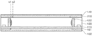
図1は、本発明の実施例による照明装置の要部を図示した断面概念図である。 FIG. 1 is a cross-sectional conceptual diagram illustrating a main part of a lighting device according to an embodiment of the present invention.
図1を参照すると、本発明の実施例による照明装置は、一面と前記一面に対向する他面に光出射面(x1、x2)が具現される光ガイド部材(130)、前記光ガイド部材(130)の内部に埋め込まれ、前記光ガイド部材の光出射面の外縁に配置される発光モジュール(120)及び前記発光モジュール内の発光素子を実装し、前記光ガイド部材の下部に配置される光透過性印刷回路基板(110)を含んで構成され得る。すなわち、本発明の実施例による照明装置は光ガイド部材の両面から光出射が行われるように具現できるようにし、配置箇所でのデザインの自由度を極大化できるようにする。 Referring to FIG. 1, in the lighting device according to the embodiment of the present invention, the light guide member (130) and the light guide member ( A light emitting module (120) embedded inside the optical guide member and arranged on the outer edge of the light emitting surface of the optical guide member and a light emitting element in the light emitting module are mounted, and the light is arranged below the optical guide member. It may be configured to include a transmissive printed circuit board (110). That is, the lighting device according to the embodiment of the present invention can be embodied so that light is emitted from both sides of the light guide member, and the degree of freedom in design at the arrangement location can be maximized.
すなわち、前記発光モジュール(120)は、前記光ガイド部材(130)の内部に埋め込まれる構造で収容され、前記発光モジュール(120)の光出射方向は前記光ガイド部材(130)の内部を向くようになる。この場合、前記光ガイド部材(130)は、光を拡散及び散乱できるようにし、光ガイド部材の両表面である光出射面(x1、x2)からそれぞれ面発光が具現できるようにする 。 That is, the light emitting module (120) is housed in a structure embedded inside the light guide member (130), and the light emitting direction of the light emitting module (120) faces the inside of the light guide member (130). become. In this case, the light guide member (130) enables light to be diffused and scattered, and surface emission can be realized from the light emitting surfaces (x1, x2) which are both surfaces of the light guide member.
特に、本発明の実施例においては、前記光ガイド部材の他面に光透過性印刷回路基板を配置して両面発光が具現できるようにする。前記光透過性印刷回路基板(110)は、透明材質のベース基板に導電性パターンが具現される印刷回路基板であり、本実施例においては前記光透過性印刷回路基板(110)の光透過率が80%以上に具現できるようにする。また、前記光ガイド部材(130)の一面の光出射面(x2)を通じて出射する光強度と前記他面の光出射面(x1)を通じて出射する光強度とが異なるように具現されるようになる。この場合、前記光ガイド部材(130)の一面の光出射面(x2)に出射する光の強度が他面の光出射面(x1)を通じて出射する光強度より大きく具現され得る。 In particular, in the embodiment of the present invention, a light-transmitting printed circuit board is arranged on the other surface of the optical guide member so that double-sided light emission can be realized. The light-transmitting printed circuit board (110) is a printed circuit board in which a conductive pattern is embodied on a base board made of a transparent material, and in this embodiment, the light transmittance of the light-transmitting printed circuit board (110). Can be realized to 80% or more. Further, the light intensity emitted through the light emitting surface (x2) on one surface of the optical guide member (130) and the light intensity emitted through the light emitting surface (x1) on the other surface are realized so as to be different. .. In this case, the intensity of the light emitted to the light emitting surface (x2) on one surface of the optical guide member (130) can be embodied to be larger than the light intensity emitted through the light emitting surface (x1) on the other surface.
前記発光モジュール(120)は、一つまたは多数の発光素子を具備することができるが、最小限の費用を具現しながらも、光効率を確保し得る構造として一つの発光モジュールに一つの発光素子を具備する構造を一例として挙げて説明する。前記発光モジュール(120)に実装される発光素子は固体発光素子であり得、一例として、LED、OLED、LD(laser diode)、Laser、VCSELのうちから選択されるいずれか一つの光源を適用することができる。本発明においては前記発光素子としてLEDを適用したものを用いて説明する。 The light emitting module (120) can be provided with one or a large number of light emitting elements, but one light emitting element is provided for one light emitting module as a structure capable of ensuring light efficiency while realizing a minimum cost. The structure including the above will be described as an example. The light emitting element mounted on the light emitting module (120) may be a solid light emitting element, and as an example, any one light source selected from LED, OLED, LD (laser diode), Laser, and VCSEL is applied. be able to. In the present invention, the light emitting element to which the LED is applied will be described.
前記発光モジュールに実装される発光素子は、側面発光型(side view type)LEDを適用することができ、これは出射する光の方向がすぐ上部に直進するのではなく、側面に向けて出射する構造の発光ダイオードを本発明の発光素子として利用できる。これによると、本発明の実施例による照明装置(100a)は、側面型発光ダイオードからなる発光素子(120)を直下型で光ガイド部材の内部に配置することになるので、光の拡散及び反射機能を具現する光ガイド部材を活用して光出射面方向に光を拡散及び誘導することによって、全体発光ユニットの個数を減少させることができるようになり、照明装置全体の重さ及び厚さを革新的に減らすことができるようになる。 The light emitting element mounted on the light emitting module can be applied with a side view type LED, which emits light toward the side surface instead of going straight to the upper part. A light emitting diode having a structure can be used as the light emitting device of the present invention. According to this, in the lighting device (100a) according to the embodiment of the present invention, the light emitting element (120) made of the side-type light emitting diode is arranged directly under the light guide member, so that the light is diffused and reflected. By diffusing and guiding light in the direction of the light emitting surface by utilizing the light guide member that embodies the function, the number of the entire light emitting unit can be reduced, and the weight and thickness of the entire lighting device can be reduced. It will be possible to reduce it innovatively.
前記光透過性印刷回路基板は、ベース基材の上に導電性パターンが具現される構造であって、柔軟性を有する基材を適用し得、基材自体で光透過度が80%以上確保されるものを利用することが望ましい。一例として、アクリル樹脂、ポリスチレン(PS)、ポリメタクリル酸メチル(PMMA)、環状オレフィンコポリマー(COC)、ポリエチレンテレフタレート(PET)、ポリイミドフィルム(PI)のうちいずれか一つを適用することができる。さらに、前記導電性パターンはAgペーストをパターニングして具現される回路パターンであり得、薄型の厚さでパターニングされるCuパターンを適用することもできる。 The light-transmitting printed circuit board has a structure in which a conductive pattern is embodied on a base base material, and a flexible base material can be applied, and the base material itself ensures light transmittance of 80% or more. It is desirable to use what is done. As an example, any one of acrylic resin, polystyrene (PS), polymethyl methacrylate (PMMA), cyclic olefin copolymer (COC), polyethylene terephthalate (PET), and polyimide film (PI) can be applied. Further, the conductive pattern can be a circuit pattern embodied by patterning Ag paste, and a Cu pattern patterned with a thin thickness can also be applied.
また、本実施例による照明装置は、前記光ガイド部材(130)と前記光透過性印刷回路基板(110)の外縁部を内側に収容して支持するベゼル部(200)を含んで構成され得る。前記ベゼル部(200)は、前記光出射面の外縁に配置され得、前記発光素子の配置箇所の上部に対応する光反射部(210)が前記光ガイド部材の中心部に突出するように具現され得る。特に、前記光反射部(210)は、反射材質であるAl、PC、PP、ABS、PBTのうちいずれか一つを含んで成り得る。または、一般的な合成樹脂や金属材質の内表面にAl、TiO2、CaCo3、BaSo4、Al2O3、Silicon、PSのうちいずれか一つを含む反射物質がコーティングされる構造で具現され得る。特に、前記光反射部(210)は、前記光反射部の末端が前記発光素子の光出射面(a1)が配置された位置以上に突出(a2)する構造で具現され得る。これは発光素子から上部に出射する光の経路を反射させて光ガイド部材の内部に再びガイドして光利用効率を極大化できるようにするためである。それに加えて、前記光反射部は、前記光ガイド部材の一面上に強い出射光で発生する樹脂材質で具現される光ガイド部材の上部面における劣化現象であるホットスポット(Hot spot)の問題を解消できる長所も具現されるようになる。 Further, the lighting device according to the present embodiment may be configured to include a bezel portion (200) that internally accommodates and supports the outer edge portion of the light guide member (130) and the light transmissive printed circuit board (110). .. The bezel portion (200) may be arranged on the outer edge of the light emitting surface, and the light reflecting portion (210) corresponding to the upper part of the arrangement portion of the light emitting element is embodied so as to project to the central portion of the light guide member. Can be done. In particular, the light reflecting unit (210) may include any one of the reflective materials Al, PC, PP, ABS, and PBT. Alternatively, it is embodied in a structure in which a reflective substance containing any one of Al, TiO 2 , CaCo 3 , BaSo 4 , Al 2 O 3 , Silicon, and PS is coated on the inner surface of a general synthetic resin or metal material. Can be done. In particular, the light reflecting portion (210) can be embodied in a structure in which the end of the light reflecting portion protrudes (a2) beyond the position where the light emitting surface (a1) of the light emitting element is arranged. This is because the path of the light emitted from the light emitting element to the upper part is reflected and guided again inside the light guide member so that the light utilization efficiency can be maximized. In addition to that, the light reflecting portion has a problem of hot spots, which is a deterioration phenomenon on the upper surface of the light guide member embodied by a resin material generated by strong emitted light on one surface of the light guide member. The advantages that can be eliminated will also be realized.
それに加えて、本実施例において前記ベゼル部(200)は、前記光反射部(210)の一端から延長して折り曲げられる側面部と下面部を具現し、前記光ガイド部材と前記光透過性印刷回路基板の外縁部を内側に収容するように収容部を具現する構造で形成することができる。このような構造は光出射面を確保しながらも、安定的な照明装置の構造を具現できるようにする。 In addition, in the present embodiment, the bezel portion (200) embodies a side surface portion and a lower surface portion that are extended and bent from one end of the light reflecting portion (210), and the light guide member and the light transmissive printing. It can be formed with a structure that embodies the accommodating portion so as to accommodate the outer edge portion of the circuit board inside. Such a structure makes it possible to realize a stable structure of a lighting device while securing a light emitting surface.
前記光ガイド部材(130)は、車両ランプのハウジングや外部の照明装置が必要な狭い箇所に自由に設計することを可能にするために柔軟性を有する樹脂材質で形成できるようにすることが望ましい。特に、本発明の実施例においては発光素子が光ガイド部材の内部に埋め込まれて発光素子の光出射発光面と樹脂材が密着しているので、高耐熱性の特徴がさらに必要になる。したがって、本実施例においては、高耐熱性を有する紫外線硬化樹脂やシリコン樹脂が適用され得る。他の例として、オリゴマーを含む紫外線硬化樹脂からなり得る。より具体的には、前記樹脂層はウレタンアクリルレートオリゴマーを主原料とするレジンを利用して形成され得る。たとえば、合成オリゴマーのウレタンアクリルレートオリゴマーとポリアクリルのポリマータイプを混合した樹脂を用いることができる。もちろん、これに低沸点希釈型反応性モノマーであるIBOA(isobornyl acrylate)、HPA(Hydroxylpropyl acrylate)、2−HEA(2−hydroxyethyl acrylate)などが混合されたモノマーをさらに含むことができ、添加剤として光開始剤(例えば、1−hydroxycyclohexyl phenyl−ketoneなど)または酸化防止剤などを混合することができる。このような混合物は高耐熱性が確保されることはもちろん、光の分散及び拡散効果が極大化できるようにする点で有利である。 It is desirable that the optical guide member (130) be made of a flexible resin material so that the housing of the vehicle lamp and the external lighting device can be freely designed in a required narrow space. .. In particular, in the embodiment of the present invention, since the light emitting element is embedded inside the light guide member and the light emitting light emitting surface of the light emitting element is in close contact with the resin material, the feature of high heat resistance is further required. Therefore, in this embodiment, an ultraviolet curable resin or a silicone resin having high heat resistance can be applied. As another example, it may consist of a UV curable resin containing an oligomer. More specifically, the resin layer can be formed by using a resin containing a urethane acrylic rate oligomer as a main raw material. For example, a resin obtained by mixing a urethane acrylic rate oligomer of a synthetic oligomer and a polymer type of polyacrylic can be used. Of course, a monomer in which a low boiling point diluted reactive monomer such as IBOA (isobornyl acrylate), HPA (Hydroxylpyl acrylate), 2-HEA (2-hydroxyethyl acrylate) and the like can be further contained can be further contained as an additive. A photoinitiator (eg, 1-hydroxycyclohexyl monomer-ketone, etc.) or an antioxidant can be mixed. Such a mixture is advantageous in that not only high heat resistance is ensured but also the light dispersion and diffusion effects can be maximized.
図2は、本発明の他の実施例による照明装置の構造を図示したものである。 FIG. 2 illustrates the structure of a lighting device according to another embodiment of the present invention.
図2を参照すると、基本的な構造は図1の実施例と同一であるが、光ガイド部材(130)の上部または前記光透過性印刷回路基板(110)の下部に配置される光学部材(140、150)をさらに具備する点で差異がある。光学部材(140、150)は光ガイド部材の光出射面を通して出る出射光の拡散度を高めて光均一度を確保できるようにする機能を遂行する。このために、前記光学部材(140、150)はシートやフィルム構造のアクリル樹脂で形成され得るが、これに限定されるものではなく、これ以外にもポリスチレン(PS)、ポリメタクリル酸メチル(PMMA)、環状オレフィンコポリマー(COC)、ポリエチレンテレフタレート(PET)、レジン(resin)のような高透過性プラスチックなど、拡散機能を遂行できるすべての材質を適用することができる。 Referring to FIG. 2, the basic structure is the same as that of the embodiment of FIG. 1, but the optical member (1) arranged in the upper part of the optical guide member (130) or the lower part of the light transmissive printed circuit board (110). There is a difference in that 140, 150) are further provided. The optical members (140, 150) perform a function of increasing the diffusivity of the emitted light emitted through the light emitting surface of the optical guide member so as to ensure the light uniformity. For this purpose, the optical members (140, 150) can be formed of a sheet or a film-structured acrylic resin, but the present invention is not limited to this, and polystyrene (PS) and polymethyl methacrylate (PMMA) are also used. ), Cyclic olefin copolymer (COC), polyethylene terephthalate (PET), highly permeable plastics such as resin, and all materials capable of performing the diffusion function can be applied.
また、図3のように、光ガイド部材(130)の光出射面のうち、透過性印刷回路基板(110)が配置された箇所の光学部材(150)の上には光拡散物質で具現される光拡散パターン(160)がさらに具現され得る。これは光透過性印刷回路基板(110)を経由して発散される光の強度と拡散を高めて、光の均一度を高めることができるようにするためである。 Further, as shown in FIG. 3, on the optical member (150) of the light emitting surface of the optical guide member (130) where the transmissive printing circuit board (110) is arranged, the light diffusing substance is embodied. The light diffusion pattern (160) can be further embodied. This is to increase the intensity and diffusion of the light emitted via the light transmissive printed circuit board (110) so that the uniformity of the light can be improved.
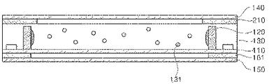
それに加えて、光拡散度を高めるためには図4のように、光ガイド部材(130)の内部に粒子構造の拡散部材(131)をさらに含んで具現され得る。前記拡散部材(131)は内部に中空(または空隙)が形成された多数のビード構造物が混合及び拡散した形態でさらに含むことができ、このような拡散部材(131)は光の反射と拡散特性を向上させる役割をする。例えば、発光モジュールから出射された光が光ガイド部材(130)の内部の拡散部材(131)に入射するようになると、光は拡散部材(131)の中空によって反射及び透過されて拡散及び集光されて光収容層の上部に出射するようになる。前記拡散部材は、シリコン(sillicon)、シリカ(silica)、グラスバブル(glass bubble)、PMMA、ウレタン(urethane)、Zn、Zr、Al2O3、アクリル(acryl)のうちから選択されるいずれか一つで構成され得、粒径は1μm〜20μmの範囲で形成され得るが、これに限定されるものではない。 In addition, in order to increase the degree of light diffusivity, as shown in FIG. 4, a diffusing member (131) having a particle structure may be further included inside the light guide member (130). The diffusing member (131) can be further contained in a form in which a large number of bead structures having hollows (or voids) formed therein are mixed and diffused, and such a diffusing member (131) reflects and diffuses light. It plays a role in improving the characteristics. For example, when the light emitted from the light emitting module is incident on the diffusing member (131) inside the light guide member (130), the light is reflected and transmitted by the hollow of the diffusing member (131) to be diffused and condensed. It will be emitted to the upper part of the light accommodating layer. The diffusion member is selected from silicon, silica, glass bubble, PMMA, urethane, Zn, Zr, Al 2 O 3 , and acrylic. It may be composed of one, and the particle size may be formed in the range of 1 μm to 20 μm, but the particle size is not limited to this.
または、本発明の実施例による他の構造を図5を参照すると、前述した光学部材の代わりに、前記光ガイド部材の一面及び前記光透過性印刷回路基板の一面と密着する光拡散樹脂層(170、180)を具現する構造で具現することができる。もちろん、その他の光ガイド層及び発光モジュール、光透過性印刷回路基板の構造は図1の構造と同一である。これは光拡散樹脂層(170、180)で具現される階は光の拡散効果を具現することができ、構造的に光ガイド部材と密着力が強いため、安定性を確保できるという点で長所が具現される。それに加えて、光拡散樹脂層の内部にも前述した図4においての拡散部材を追加できるようになるので、光の均一度(uniformity)を確保できるようにすることにおいて非常に有利になる。もちろん、図5に図示されたように、光ガイド部材の内部にも拡散部材(131)が含まれ得ることは図4の実施例で前述したのと同一である。 Alternatively, referring to FIG. 5 for another structure according to the embodiment of the present invention, instead of the above-mentioned optical member, a light diffusing resin layer (which is in close contact with one surface of the optical guide member and one surface of the light transmissive printing circuit substrate). It can be embodied in a structure that embodies 170, 180). Of course, the structures of the other optical guide layer, the light emitting module, and the optical transmissive printed circuit board are the same as those of FIG. This is an advantage in that the floor embodied by the light diffusing resin layer (170, 180) can realize the light diffusing effect and structurally has strong adhesion to the light guide member, so that stability can be ensured. Is embodied. In addition to that, the diffusion member in FIG. 4 described above can be added to the inside of the light diffusion resin layer, which is very advantageous in ensuring the uniformity of light. Of course, as shown in FIG. 5, the fact that the diffusion member (131) can be included inside the optical guide member is the same as described above in the embodiment of FIG.
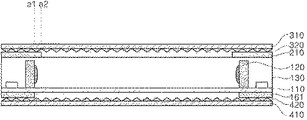
図6は、図2において前述した本発明の実施例の変形構造であって、光が図6に図示されたように、光出射面に形成されるイメージが光ガイド部材の深さ方向に進行するような深み感と立体感を具現できるようにする点で差異がある。このため、前記光ガイド部材(130)の一面または他面上に光学部材(310、410)の表面に前記光出射面の方向に突出する突出型光学パターン(320、420)が具現される光学部材を配置できるようにする。この場合、前記突出型光学パターン(320、420)は前記光ガイド層の光出射面が配置される方向の光学部材表面に形成され得る。このように単純な面発光ではなく、突出光学パターンが形成された光学部材を具備することによって幾何学的光パターンを形成させて視野角によって光の形状や立体感が変わる効果を具現できるようになる(図7参照)。 FIG. 6 is a modified structure of the embodiment of the present invention described above in FIG. 2, and as shown in FIG. 6, the image formed on the light emitting surface advances in the depth direction of the light guide member. There is a difference in that it makes it possible to realize a sense of depth and a three-dimensional effect. Therefore, optics embodying a protruding optical pattern (320, 420) projecting in the direction of the light emitting surface on the surface of the optical member (310, 410) on one surface or the other surface of the optical guide member (130). Allow members to be placed. In this case, the protruding optical pattern (320, 420) may be formed on the surface of the optical member in the direction in which the light emitting surface of the optical guide layer is arranged. By providing an optical member on which a protruding optical pattern is formed, instead of such a simple surface emission, a geometric light pattern can be formed so that the effect of changing the shape and three-dimensional effect of light depending on the viewing angle can be realized. (See Fig. 7).
前記突出光学パターン(320、420)は、透明基材(410)の表面に突出するパターンの断面が多角形構造であって、全体的にはライン型パターンで具現されたり、または多数の単位プリズムレンズパターンを具備したプリズムシート、マイクロレンズアレイシート乃至レンチキュラーレンズシートのうちいずれか一つまたはこれらの組合せにより具現され得る。 The projecting optical pattern (320, 420) has a polygonal cross section of the pattern projecting from the surface of the transparent base material (410), and is embodied as a line pattern as a whole, or a large number of unit prisms. It can be embodied by any one of a prism sheet, a microlens array sheet or a lenticular lens sheet provided with a lens pattern, or a combination thereof.
本発明の実施例によると、前記光ガイド部材を柔軟性を有するレジンで具現して従来の導光板が占めていた厚さを革新的に減少させることができるようになり、全体製品の薄型化が具現できるようになり、透明印刷回路基板を用いて光出射面が両方向に具現できるようになるので、設置箇所の屈曲面にも容易に適用できる利点、デザインの自由度を向上させることができる利点及びその他の車両照明やフレキシブルディスプレーにも応用して適用が可能な利点を有するようになる。 According to the embodiment of the present invention, the optical guide member can be embodied in a flexible resin to innovatively reduce the thickness occupied by the conventional light guide plate, and the overall product can be made thinner. Can be realized, and the light emitting surface can be realized in both directions using a transparent printed circuit board, so that the advantage that it can be easily applied to the bent surface of the installation location and the degree of freedom in design can be improved. It will have advantages and other advantages that can be applied to vehicle lighting and flexible displays.
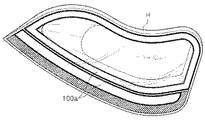
図8は、前述した図1ないし図7の本発明の実施例による照明装置を車両用ランプに適用したものを例示したものである。 FIG. 8 illustrates an example in which the lighting device according to the embodiment of the present invention of FIGS. 1 to 7 described above is applied to a vehicle lamp.
図8を参照すると、本発明の実施例よる照明装置(100a)は軟性回路基板及びレジンを利用した光ガイド部材が適用され、それ自体が一定の柔軟性を有するようになる。それに加えて、また両面発光型構造を具現して形成されるので、デザインの自由度が高くなる。したがって、図8に図示したように屈曲が形成された車両用ヘッドライトハウジングにも容易に装着でき、これによって、ハウジングと結合した完成品のデザイン自由度を向上させることができる効果及びデザイン自由度の向上にもかかわらず、均一な輝度及び照度を確保できるという効果を収めることができるようになる。 Referring to FIG. 8, the lighting device (100a) according to the embodiment of the present invention is applied with an optical guide member using a flexible circuit board and a resin, and itself has a certain degree of flexibility. In addition to that, since it is formed by embodying a double-sided light emitting structure, the degree of freedom in design is increased. Therefore, as shown in FIG. 8, it can be easily attached to the headlight housing for a vehicle having a bend formed therein, whereby the effect and the degree of freedom in design that can improve the design freedom of the finished product combined with the housing can be improved. Despite the improvement of the above, the effect of ensuring uniform brightness and illuminance can be obtained.
特に、前述したように、非常に狭い空間で具現されても、光の混合を具現して 光幅を拡張できるようになり、これは発光素子と図7のように深み感を有する立体光のイメージとの空間を最小化する構造で具現することもできる。 In particular, as described above, even if it is realized in a very narrow space, it becomes possible to realize the mixing of light and expand the light width, which is the light emitting element and the three-dimensional light having a sense of depth as shown in FIG. It can also be embodied in a structure that minimizes the space with the image.
前述したような本発明の詳細な説明においては、具体的な実施例に関して説明した。しかし、本発明の範疇から外れない限度内においては様々な変形が可能である。本発明の技術的思想は本発明の前述した実施例に限定して定められてはならず、特許請求の範囲だけでなくこの特許請求の範囲と均等なものなどによって定められなければならない。
In the detailed description of the present invention as described above, specific examples have been described. However, various modifications are possible within the limits of the present invention. The technical idea of the present invention should not be defined only in the above-mentioned embodiment of the present invention, but should be defined not only by the scope of claims but also by the equivalent of the scope of claims.
Claims (14)
前記光ガイド部材の内部に埋め込まれ、前記光ガイド部材の前記第1光出射面及び前記第2光出射面の外縁に配置される発光モジュールと、
前記発光モジュール内の発光素子を実装し、前記光ガイド部材の下部に配置される光透過性印刷回路基板と、
前記光透過性印刷回路基板の下部に配置され、前記光ガイド部材の前記第2光出射面を通して出る出射光の拡散度を高める第1光学部材と、
前記光透過性印刷回路基板と前記第1光学部材の間に配置される光拡散パターンと、
前記光ガイド部材の前記第1光出射面及び前記第2光出射面の外縁に配置され、前記発光素子の上部に対応する光反射部とを含み、
前記光ガイド部材の一面方向と前記他面方向に発光する照明装置。 An optical guide member in which the first light emitting surface is embodied on one surface and the second light emitting surface is embodied on the other surface facing the one surface.
A light emitting module embedded inside the optical guide member and arranged on the outer edge of the first light emitting surface and the second light emitting surface of the optical guide member.
A light-transmitting printed circuit board on which a light-emitting element in the light-emitting module is mounted and arranged below the light-guided member, and a light-transmitting printed circuit board.
A first optical member which is arranged under the light transmissive printed circuit board and enhances the diffusivity of the emitted light emitted through the second light emitting surface of the optical guide member.
A light diffusion pattern arranged between the light-transmitting printed circuit board and the first optical member,
A light reflecting portion arranged on the outer edge of the first light emitting surface and the second light emitting surface of the light guide member and corresponding to the upper part of the light emitting element is included.
A lighting device that emits light in one side direction and the other side direction of the light guide member.
前記光ガイド部材の外縁部と前記光透過性印刷回路基板の外縁部とを内側に収容する収容部を有する、請求項5または請求項6に記載の照明装置。 The bezel portion extends from the other end of the light reflecting portion adjacent to the upper surface of the light guide member.
The lighting device according to claim 5 or 6, further comprising an accommodating portion for accommodating an outer edge portion of the optical guide member and an outer edge portion of the light transmissive printed circuit board inside.
前記光反射部は前記光ガイド部材の上面の上に樹脂材質で形成される、請求項1ないし 請求項9のうちいずれか一つに記載の照明装置。 The optical guide member is made of a soft resin material and is made of a soft resin material.
The lighting device according to any one of claims 1 to 9, wherein the light reflecting portion is formed of a resin material on the upper surface of the light guide member.
前記光透過性印刷回路基板の外縁に配置されて発光素子を有する発光モジュールと、
内部に前記発光モジュールが埋め込まれ、上面及び下面に光を出射する第1光出射面及び第2光出射面をそれぞれ有する光ガイド部材と、
前記光透過性印刷回路基板の下部に配置され、前記光ガイド部材の前記第2光出射面を通して出る出射光の拡散度を高める光学部材と、
前記光透過性印刷回路基板と前記光学部材の間に配置される光拡散パターンと、
前記光ガイド部材の前記第1光出射面及び前記第2光出射面の外縁に配置され、前記発光素子の上部に対応する光反射部とを含み、
前記光透過性印刷回路基板の上面は前記光ガイド部材の下面と接触し、
前記発光モジュールは前記光ガイド部材の前記第1光出射面及び前記第2光出射面の外側に配置され、
前記発光素子の発光面は前記光ガイド部材と接着されて前記光ガイド部材の内部方向に光を放出し、
前記光ガイド部材の上面方向と前記光透過性印刷回路基板の他面方向に発光する照明装置。 A base base material made of a transparent material, a light-transmitting printed circuit board in which a conductive pattern is arranged on the base base material, and a light-transmitting printed circuit board.
A light emitting module arranged on the outer edge of the light transmissive printed circuit board and having a light emitting element, and a light emitting module.
An optical guide member in which the light emitting module is embedded and has a first light emitting surface and a second light emitting surface that emit light on the upper surface and the lower surface, respectively.
An optical member arranged under the light-transmitting printed circuit board and increasing the diffusivity of the emitted light emitted through the second light emitting surface of the optical guide member.
A light diffusion pattern arranged between the light-transmitting printed circuit board and the optical member,
A light reflecting portion arranged on the outer edge of the first light emitting surface and the second light emitting surface of the light guide member and corresponding to the upper part of the light emitting element is included.
The upper surface of the light transmissive printed circuit board comes into contact with the lower surface of the optical guide member, and is in contact with the lower surface of the optical guide member.
The light emitting module is arranged outside the first light emitting surface and the second light emitting surface of the light guide member.
The light emitting surface of the light emitting element is adhered to the light guide member and emits light in the internal direction of the light guide member.
A lighting device that emits light in the direction of the upper surface of the optical guide member and in the direction of the other surface of the light-transmitting printed circuit board.
前記光反射部は前記光ガイド部材の上面の上に樹脂材質で形成される、請求項11に記載の照明装置。 The optical guide member is made of a soft resin material and is made of a soft resin material.
The lighting device according to claim 11, wherein the light reflecting portion is formed of a resin material on the upper surface of the light guide member.
Applications Claiming Priority (3)
| Application Number | Priority Date | Filing Date | Title |
|---|---|---|---|
| KR10-2015-0075398 | 2015-05-28 | ||
| KR1020150075398A KR102397362B1 (en) | 2015-05-28 | 2015-05-28 | Light unit and Lamp unit for automobile of using the same |
| PCT/KR2016/005648 WO2016190709A1 (en) | 2015-05-28 | 2016-05-27 | Lighting device and vehicle lamp including same |
Publications (3)
| Publication Number | Publication Date |
|---|---|
| JP2018517248A JP2018517248A (en) | 2018-06-28 |
| JP2018517248A5 JP2018517248A5 (en) | 2021-03-25 |
| JP6974838B2 true JP6974838B2 (en) | 2021-12-01 |
Family
ID=57394213
Family Applications (1)
| Application Number | Title | Priority Date | Filing Date |
|---|---|---|---|
| JP2017560935A Active JP6974838B2 (en) | 2015-05-28 | 2016-05-27 | Lighting equipment and vehicle lamps including it |
Country Status (6)
| Country | Link |
|---|---|
| US (1) | US10436404B2 (en) |
| EP (1) | EP3306179B1 (en) |
| JP (1) | JP6974838B2 (en) |
| KR (1) | KR102397362B1 (en) |
| CN (1) | CN107683387B (en) |
| WO (1) | WO2016190709A1 (en) |
Families Citing this family (12)
| Publication number | Priority date | Publication date | Assignee | Title |
|---|---|---|---|---|
| CZ2017391A3 (en) * | 2017-07-03 | 2019-01-16 | Varroc Lighting Systems, s.r.o. | Lighting apparatus, in particular a signal lamp for motor vehicles |
| FR3070070A1 (en) * | 2017-08-14 | 2019-02-15 | Koito Manufacturing Co., Ltd. | ROD-SHAPED LIGHT GUIDE AND VEHICLE LAMP |
| KR102084914B1 (en) | 2017-08-28 | 2020-03-06 | 현대모비스 주식회사 | Lamp module for vehicle |
| KR102575163B1 (en) * | 2018-03-05 | 2023-09-06 | 현대자동차주식회사 | Light guide for vehicle |
| CN111365676A (en) * | 2018-12-26 | 2020-07-03 | 深圳市绎立锐光科技开发有限公司 | Light emitting device |
| KR102071220B1 (en) * | 2019-04-23 | 2020-01-31 | 현대모비스 주식회사 | Composite optical sheet and lamp module for vehicle comprising the same |
| JP2022535912A (en) * | 2019-06-04 | 2022-08-10 | エルジー イノテック カンパニー リミテッド | Lighting module and lighting device provided with the same |
| EP4034806A4 (en) * | 2019-09-27 | 2023-11-01 | Flex-N-Gate Advanced Product Development, LLC | Double-sided optical sheets |
| FR3104679B1 (en) * | 2019-12-13 | 2022-07-15 | Valeo Vision | Optical part and light module for motor vehicle |
| DE102020121008B4 (en) | 2020-08-10 | 2022-02-17 | Dr. Ing. H.C. F. Porsche Aktiengesellschaft | motor vehicle rear light |
| DE102021116099A1 (en) | 2020-11-02 | 2022-05-05 | Olsa S.P.A. | AUTOMOTIVE OPTICAL DEVICE, AUTOMOTIVE LAMP AND AMBIENT LIGHT |
| DE102021001512B4 (en) * | 2021-03-23 | 2023-03-16 | Mercedes-Benz Group AG | Decorative part with a surface light guide |
Family Cites Families (33)
| Publication number | Priority date | Publication date | Assignee | Title |
|---|---|---|---|---|
| JP4576697B2 (en) * | 2000-10-25 | 2010-11-10 | セイコーエプソン株式会社 | LIGHTING DEVICE, LIQUID CRYSTAL DISPLAY DEVICE, AND ELECTRONIC DEVICE |
| JP4048844B2 (en) * | 2002-06-17 | 2008-02-20 | カシオ計算機株式会社 | Surface light source and display device using the same |
| US7286280B2 (en) * | 2004-05-07 | 2007-10-23 | The University Of British Columbia | Brightness enhancement film for backlit image displays |
| US8272758B2 (en) * | 2005-06-07 | 2012-09-25 | Oree, Inc. | Illumination apparatus and methods of forming the same |
| GB2454928B (en) * | 2007-11-23 | 2009-11-18 | Iti Scotland Ltd | Light guides |
| WO2010014032A1 (en) | 2008-07-07 | 2010-02-04 | Glo Ab | A nanostructured LED |
| TWI596406B (en) * | 2009-03-05 | 2017-08-21 | Iti蘇格蘭有限公司 | Light guides |
| US9625641B2 (en) | 2009-03-05 | 2017-04-18 | Design Led Products Limited | Light guides |
| US8794812B2 (en) * | 2009-05-01 | 2014-08-05 | Abl Ip Holding Llc | Light emitting devices and applications thereof |
| JP5401649B2 (en) | 2009-05-26 | 2014-01-29 | 株式会社オプトデザイン | Lighting device |
| JP2011070865A (en) | 2009-09-25 | 2011-04-07 | Shin Etsu Polymer Co Ltd | Light guide body |
| JP5441622B2 (en) | 2009-11-04 | 2014-03-12 | 森ビル株式会社 | Panel type lighting fixture |
| DE102010018034A1 (en) * | 2010-04-23 | 2011-10-27 | Osram Opto Semiconductors Gmbh | Surface light guide and surface radiator |
| TWI425278B (en) * | 2010-05-05 | 2014-02-01 | 揚昇照明股份有限公司 | Backlight module |
| JP5300817B2 (en) * | 2010-10-18 | 2013-09-25 | 三菱電機株式会社 | Illumination light source and illumination device |
| KR101191213B1 (en) * | 2010-11-02 | 2012-10-15 | 엘지전자 주식회사 | Lighting apparatus |
| JP5908456B2 (en) * | 2011-03-07 | 2016-04-26 | 有限会社 エー・ジー・ケー | Exhibition panel suspension and lighting device |
| KR101402814B1 (en) * | 2011-04-04 | 2014-06-03 | 엘지이노텍 주식회사 | Lamp device within resin layer for light-guide and LCD using the same |
| KR101839869B1 (en) * | 2011-05-27 | 2018-03-20 | 엘지이노텍 주식회사 | Lighting module |
| GB2498347A (en) * | 2012-01-10 | 2013-07-17 | Design Led Products Ltd | A lighting panel with side mounted top emitting LEDs |
| JP2013218059A (en) * | 2012-04-06 | 2013-10-24 | Fujikura Ltd | Planar light emitting device |
| KR101871374B1 (en) * | 2012-04-09 | 2018-06-27 | 엘지이노텍 주식회사 | A light emitting lamp |
| CN107883219B (en) * | 2012-08-10 | 2020-10-09 | Lg伊诺特有限公司 | Lighting device |
| US8944662B2 (en) * | 2012-08-13 | 2015-02-03 | 3M Innovative Properties Company | Diffractive luminaires |
| KR20140026019A (en) * | 2012-08-24 | 2014-03-05 | 에스케이씨하스디스플레이필름(유) | Optical sheet for surface light source apparatus |
| WO2014051394A1 (en) * | 2012-09-27 | 2014-04-03 | 엘지이노텍 주식회사 | Illuminating device and vehicle lamp comprising same |
| GB2506625A (en) | 2012-10-04 | 2014-04-09 | Bae Systems Plc | LCD backlight display |
| KR101775802B1 (en) * | 2012-10-26 | 2017-09-06 | 미쯔비시 케미컬 주식회사 | Light-guiding body, light-guiding body fabrication method, optical shutter, and planar light source device |
| RU2654541C2 (en) * | 2012-10-26 | 2018-05-21 | Филипс Лайтинг Холдинг Б.В. | Lighting device and lighting system |
| KR102005529B1 (en) * | 2012-12-17 | 2019-07-30 | 엘지이노텍 주식회사 | Automobile lamp |
| KR20140078374A (en) * | 2012-12-17 | 2014-06-25 | 엘지이노텍 주식회사 | Light unit and Lamp unit for automobile of using the same |
| JP2015049983A (en) * | 2013-08-30 | 2015-03-16 | 市光工業株式会社 | Vehicular lighting system |
| CN104121516B (en) * | 2014-07-11 | 2016-08-17 | 京东方科技集团股份有限公司 | Lamp holder and desk lamp for desk lamp |
-
2015
- 2015-05-28 KR KR1020150075398A patent/KR102397362B1/en active IP Right Grant
-
2016
- 2016-05-27 US US15/577,264 patent/US10436404B2/en active Active
- 2016-05-27 CN CN201680031026.XA patent/CN107683387B/en active Active
- 2016-05-27 WO PCT/KR2016/005648 patent/WO2016190709A1/en active Application Filing
- 2016-05-27 JP JP2017560935A patent/JP6974838B2/en active Active
- 2016-05-27 EP EP16800348.1A patent/EP3306179B1/en active Active
Also Published As
| Publication number | Publication date |
|---|---|
| KR102397362B1 (en) | 2022-05-20 |
| CN107683387A (en) | 2018-02-09 |
| WO2016190709A1 (en) | 2016-12-01 |
| KR20160139831A (en) | 2016-12-07 |
| CN107683387B (en) | 2021-04-27 |
| US10436404B2 (en) | 2019-10-08 |
| US20180149325A1 (en) | 2018-05-31 |
| EP3306179A1 (en) | 2018-04-11 |
| EP3306179B1 (en) | 2019-10-16 |
| EP3306179A4 (en) | 2018-04-11 |
| JP2018517248A (en) | 2018-06-28 |
Similar Documents
| Publication | Publication Date | Title |
|---|---|---|
| JP6974838B2 (en) | Lighting equipment and vehicle lamps including it | |
| JP6370537B2 (en) | Lighting device | |
| EP3144587B1 (en) | Light source module and lighting apparatus having same | |
| JP5735565B2 (en) | Lighting device | |
| CN104246360A (en) | Lighting device | |
| KR102305599B1 (en) | Light unit and Lamp unit for automobile of using the same | |
| KR101934427B1 (en) | Illuminating device | |
| KR102497470B1 (en) | Lighting package and Automobile lamp using the same | |
| KR102125679B1 (en) | Illuminating device and lamp for vehicle including the same | |
| KR102468105B1 (en) | Light unit and Lamp unit for automobile of using the same | |
| KR101368852B1 (en) | Illuminating device | |
| KR102292690B1 (en) | Illuminating device and lamp for vehicle including the same | |
| KR102387192B1 (en) | Light unit and Lamp unit for automobile of using the same | |
| US10746355B2 (en) | Lighting device | |
| KR102160759B1 (en) | Lighting Device | |
| KR102058006B1 (en) | Illuminating device | |
| KR101368843B1 (en) | Illuminating device | |
| KR102222649B1 (en) | Light device | |
| KR102034081B1 (en) | Illuminating device | |
| KR20210104010A (en) | Illuminating device and lamp for vehicle including the same | |
| KR101446912B1 (en) | Illuminating device | |
| KR20120062123A (en) | Light emitting device package and backlight unit including the same |
Legal Events
| Date | Code | Title | Description |
|---|---|---|---|
| A521 | Request for written amendment filed |
Free format text: JAPANESE INTERMEDIATE CODE: A523 Effective date: 20171129 |
|
| A621 | Written request for application examination |
Free format text: JAPANESE INTERMEDIATE CODE: A621 Effective date: 20190515 |
|
| A977 | Report on retrieval |
Free format text: JAPANESE INTERMEDIATE CODE: A971007 Effective date: 20200416 |
|
| A131 | Notification of reasons for refusal |
Free format text: JAPANESE INTERMEDIATE CODE: A131 Effective date: 20200428 |
|
| A521 | Request for written amendment filed |
Free format text: JAPANESE INTERMEDIATE CODE: A523 Effective date: 20200722 |
|
| A131 | Notification of reasons for refusal |
Free format text: JAPANESE INTERMEDIATE CODE: A131 Effective date: 20201110 |
|
| A524 | Written submission of copy of amendment under article 19 pct |
Free format text: JAPANESE INTERMEDIATE CODE: A524 Effective date: 20210209 |
|
| A131 | Notification of reasons for refusal |
Free format text: JAPANESE INTERMEDIATE CODE: A131 Effective date: 20210309 |
|
| RD13 | Notification of appointment of power of sub attorney |
Free format text: JAPANESE INTERMEDIATE CODE: A7433 Effective date: 20210513 |
|
| A521 | Request for written amendment filed |
Free format text: JAPANESE INTERMEDIATE CODE: A523 Effective date: 20210603 |
|
| A521 | Request for written amendment filed |
Free format text: JAPANESE INTERMEDIATE CODE: A821 Effective date: 20210514 |
|
| TRDD | Decision of grant or rejection written | ||
| A01 | Written decision to grant a patent or to grant a registration (utility model) |
Free format text: JAPANESE INTERMEDIATE CODE: A01 Effective date: 20211005 |
|
| A61 | First payment of annual fees (during grant procedure) |
Free format text: JAPANESE INTERMEDIATE CODE: A61 Effective date: 20211028 |
|
| R150 | Certificate of patent or registration of utility model |
Ref document number: 6974838 Country of ref document: JP Free format text: JAPANESE INTERMEDIATE CODE: R150 |