JP6972945B2 - Reader, image processing program and image production method - Google Patents
Reader, image processing program and image production method Download PDFInfo
- Publication number
- JP6972945B2 JP6972945B2 JP2017216897A JP2017216897A JP6972945B2 JP 6972945 B2 JP6972945 B2 JP 6972945B2 JP 2017216897 A JP2017216897 A JP 2017216897A JP 2017216897 A JP2017216897 A JP 2017216897A JP 6972945 B2 JP6972945 B2 JP 6972945B2
- Authority
- JP
- Japan
- Prior art keywords
- image
- region
- wrinkle
- brightness
- specified
- Prior art date
- Legal status (The legal status is an assumption and is not a legal conclusion. Google has not performed a legal analysis and makes no representation as to the accuracy of the status listed.)
- Active
Links
Images


Classifications
-
- H—ELECTRICITY
- H04—ELECTRIC COMMUNICATION TECHNIQUE
- H04N—PICTORIAL COMMUNICATION, e.g. TELEVISION
- H04N1/00—Scanning, transmission or reproduction of documents or the like, e.g. facsimile transmission; Details thereof
- H04N1/46—Colour picture communication systems
- H04N1/56—Processing of colour picture signals
- H04N1/60—Colour correction or control
- H04N1/6094—Colour correction or control depending on characteristics of the input medium, e.g. film type, newspaper
-
- H—ELECTRICITY
- H04—ELECTRIC COMMUNICATION TECHNIQUE
- H04N—PICTORIAL COMMUNICATION, e.g. TELEVISION
- H04N1/00—Scanning, transmission or reproduction of documents or the like, e.g. facsimile transmission; Details thereof
- H04N1/00795—Reading arrangements
- H04N1/00798—Circuits or arrangements for the control thereof, e.g. using a programmed control device or according to a measured quantity
- H04N1/00814—Circuits or arrangements for the control thereof, e.g. using a programmed control device or according to a measured quantity according to a detected condition or state of the reading apparatus, e.g. temperature
-
- H—ELECTRICITY
- H04—ELECTRIC COMMUNICATION TECHNIQUE
- H04N—PICTORIAL COMMUNICATION, e.g. TELEVISION
- H04N1/00—Scanning, transmission or reproduction of documents or the like, e.g. facsimile transmission; Details thereof
- H04N1/04—Scanning arrangements, i.e. arrangements for the displacement of active reading or reproducing elements relative to the original or reproducing medium, or vice versa
- H04N1/203—Simultaneous scanning of two or more separate pictures, e.g. two sides of the same sheet
- H04N1/2032—Simultaneous scanning of two or more separate pictures, e.g. two sides of the same sheet of two pictures corresponding to two sides of a single medium
-
- H—ELECTRICITY
- H04—ELECTRIC COMMUNICATION TECHNIQUE
- H04N—PICTORIAL COMMUNICATION, e.g. TELEVISION
- H04N1/00—Scanning, transmission or reproduction of documents or the like, e.g. facsimile transmission; Details thereof
- H04N1/46—Colour picture communication systems
- H04N1/56—Processing of colour picture signals
- H04N1/58—Edge or detail enhancement; Noise or error suppression, e.g. colour misregistration correction
-
- H—ELECTRICITY
- H04—ELECTRIC COMMUNICATION TECHNIQUE
- H04N—PICTORIAL COMMUNICATION, e.g. TELEVISION
- H04N1/00—Scanning, transmission or reproduction of documents or the like, e.g. facsimile transmission; Details thereof
- H04N1/46—Colour picture communication systems
- H04N1/56—Processing of colour picture signals
- H04N1/60—Colour correction or control
- H04N1/6058—Reduction of colour to a range of reproducible colours, e.g. to ink- reproducible colour gamut
-
- H—ELECTRICITY
- H04—ELECTRIC COMMUNICATION TECHNIQUE
- H04N—PICTORIAL COMMUNICATION, e.g. TELEVISION
- H04N1/00—Scanning, transmission or reproduction of documents or the like, e.g. facsimile transmission; Details thereof
- H04N1/46—Colour picture communication systems
- H04N1/56—Processing of colour picture signals
- H04N1/60—Colour correction or control
- H04N1/6083—Colour correction or control controlled by factors external to the apparatus
- H04N1/6086—Colour correction or control controlled by factors external to the apparatus by scene illuminant, i.e. conditions at the time of picture capture, e.g. flash, optical filter used, evening, cloud, daylight, artificial lighting, white point measurement, colour temperature
-
- H—ELECTRICITY
- H04—ELECTRIC COMMUNICATION TECHNIQUE
- H04N—PICTORIAL COMMUNICATION, e.g. TELEVISION
- H04N1/00—Scanning, transmission or reproduction of documents or the like, e.g. facsimile transmission; Details thereof
- H04N1/46—Colour picture communication systems
- H04N1/56—Processing of colour picture signals
- H04N1/60—Colour correction or control
- H04N1/62—Retouching, i.e. modification of isolated colours only or in isolated picture areas only
Description
本発明は、読取装置、画像処理プログラムおよび画像生産方法に関する。 The present invention relates to a reader, an image processing program and an image production method.
スキャナーによる読取対象となる原稿には皺(原稿の折り目、等とも言う。)が発生していることがある。
なお、表裏の原稿画像の位置合わせを行い、位置合わせした原稿画像の画素値に基づき非凹凸領域を判定し、非凹凸領域以外の領域における表裏の原稿画像の画素値の平均値を取得し、非凹凸領域以外の領域における画素値が近い部分を結んだ等色線を生成し、画素値の平均値及び等色線に基づき原稿画像の凹凸領域を判定し、原稿画像の凹凸領域の画像を補正する画像処理装置が開示されている(特許文献1参照)。
Wrinkles (also referred to as creases in the document, etc.) may occur in the document to be scanned by the scanner.
The front and back original images are aligned, the non-concavo-convex region is determined based on the pixel values of the aligned original images, and the average value of the pixel values of the front and back original images in the region other than the non-concave region is obtained. A uniform color line connecting portions having similar pixel values in a region other than the non-concave and convex region is generated, the uneven region of the original image is determined based on the average value of the pixel values and the uniform color line, and the image of the uneven region of the original image is obtained. An image processing apparatus for correction is disclosed (see Patent Document 1).
従来技術においては、原稿の表と裏とで色や濃度が異なる場合等に、原稿の皺を適切に検出することが難しかった。また、前記文献1では、原稿の凹凸(皺)が重なった文字や絵柄の領域については補正の対象とされない(前記文献1の段落0020)。
In the prior art, it has been difficult to properly detect wrinkles in a document when the colors and densities of the front and back of the document are different. Further, in the above-mentioned
本発明は上述の課題の少なくとも一つに対応してなされたものであり、原稿の皺を高精度に検出し、また、検出した皺に対して適切な処理を実行可能な読取装置、画像処理プログラムおよび画像生産方法を提供する。 The present invention has been made in response to at least one of the above-mentioned problems, and is a reading device and image processing capable of detecting wrinkles in a document with high accuracy and performing appropriate processing for the detected wrinkles. Provides programs and image production methods.
本発明の態様の1つは、読取装置は、原稿の第1面と前記第1面の裏側の第2面とを読み取ることにより前記第1面の読取画像である第1画像と前記第2面の読取画像である第2画像とを生成する読取部と、生成された前記第1画像と前記第2画像との両方における同じ位置に、明るさが凸状に変化する明部と前記明部と接して明るさが凹状に変化する暗部とを有する明るさ変動領域が存在する場合に、前記明るさ変動領域を皺領域に特定する特定部と、特定された前記皺領域に対する画像処理を施した前記第1画像を出力する出力部と、を備える。 One aspect of the present invention is that the reading device reads the first surface of the document and the second surface on the back side of the first surface to read the first image and the second surface, which are the scanned images of the first surface. A bright part and the bright part whose brightness changes convexly at the same position in both the first image and the second image generated, and the reading unit that generates the second image that is the reading image of the surface. When there is a brightness fluctuation region having a dark portion in which the brightness changes in a concave shape in contact with the portion, the image processing for the specific portion for specifying the brightness fluctuation region as the wrinkle region and the specified wrinkle region is performed. It is provided with an output unit for outputting the first image applied.
当該構成によれば、読取装置は、原稿の両面の読み取りにより生成した第1画像および第2画像の同じ位置に、明るさが凸状に変化する明部と明部と接して明るさが凹状に変化する暗部とを有する明るさ変動領域が存在する場合に、この明るさ変動領域を原稿の皺の読取結果としての皺領域に特定する。つまり、明るさに所定の変動パターンが見られる領域に基づいて皺領域を特定することで、原稿の第1面(第1画像)と第2面(第2画像)とに色や濃度の違いがあったとしても原稿の皺を特定(検出)することができる。 According to this configuration, the reading device has a concave brightness in contact with a bright portion whose brightness changes convexly and a bright portion at the same position of the first image and the second image generated by scanning both sides of the original. When there is a brightness fluctuation region having a dark portion that changes to, this brightness fluctuation region is specified as a wrinkle region as a result of reading the wrinkles of the document. That is, by specifying the wrinkle region based on the region where a predetermined fluctuation pattern is seen in the brightness, the difference in color and density between the first surface (first image) and the second surface (second image) of the document is obtained. Even if there is, it is possible to identify (detect) the wrinkles of the original.
本発明の態様の1つは、前記出力部は、前記皺領域の色を平坦化させる画像処理を施した前記第1画像を出力するとしてもよい。
当該構成によれば、皺の存在が除去された第1画像を出力することができる。むろん、前記出力部は、このような画像処理後の第1画像に加えて、前記皺領域の色を平坦化させる画像処理を施した前記第2画像を出力するとしてもよい。つまり、原稿の片面についてだけ前記画像処理後の画像を出力してもよいし、原稿の両面について前記画像処理後の画像を出力してもよい。
In one aspect of the present invention, the output unit may output the first image that has been subjected to image processing for flattening the color of the wrinkle region.
According to this configuration, it is possible to output a first image in which the presence of wrinkles is removed. Of course, in addition to the first image after such image processing, the output unit may output the second image subjected to image processing for flattening the color of the wrinkle region. That is, the image after the image processing may be output only on one side of the document, or the image after the image processing may be output on both sides of the document.
本発明の態様の1つは、前記特定部は、前記同じ位置において前記第1画像と前記第2画像との一方にのみ前記明るさ変動領域が存在していて、当該一方に存在する前記明るさ変動領域が前記皺領域に特定した他の領域と連続している場合に、当該一方に存在する前記明るさ変動領域を前記皺領域に特定することしてもよい。
当該構成によれば、第1画像と第2画像との同じ位置のうち、一方には前記明るさ変動領域が存在するが、他方には文字等の存在に起因して前記明るさ変動領域が存在すると判別できない場合であっても、近隣の皺領域との連続性に基づいて、前記一方に存在する前記明るさ変動領域を皺領域に特定する。結果、より高い精度で原稿の皺を特定することができる。
In one aspect of the present invention, the specific portion has the brightness fluctuation region existing only in one of the first image and the second image at the same position, and the brightness existing in the one. When the fluctuation region is continuous with the other region specified in the wrinkle region, the brightness fluctuation region existing in one of the wrinkle regions may be specified in the wrinkle region.
According to the configuration, the brightness fluctuation region exists on one of the same positions of the first image and the second image, but the brightness fluctuation region is present on the other due to the presence of characters and the like. Even if it cannot be determined that it exists, the brightness fluctuation region existing in one of the above is specified as the wrinkle region based on the continuity with the neighboring wrinkle region. As a result, the wrinkles of the original can be identified with higher accuracy.
本発明の態様の1つは、前記出力部は、前記同じ位置において前記第1画像にのみ前記明るさ変動領域が存在し、当該第1画像に存在する前記明るさ変動領域が前記皺領域に特定された場合、当該第1画像で特定された前記皺領域の色を平坦化させる画像処理を施した前記第1画像を出力し、前記同じ位置において前記第2画像にのみ前記明るさ変動領域が存在し、当該第2画像に存在する前記明るさ変動領域が前記皺領域に特定された場合、当該第2画像で特定された前記皺領域の裏の前記第1画像側の領域を対象として、前記第1画像内に表現されたオブジェクトのエッジの外側の色を平坦化させる画像処理を施した前記第1画像を出力する、としてもよい。
当該構成によれば、皺の存在が除去された第1画像を出力することができる。また、当該構成によれば第1画像において皺とオブジェクト(例えば文字や記号)が重なっている場合には、オブジェクトの色は保持しつつオブジェクトと交差する皺についてその存在を的確に除去することができる。
One aspect of the present invention is that the output unit has the brightness fluctuation region only in the first image at the same position, and the brightness fluctuation region existing in the first image is in the wrinkle region. When specified, the first image subjected to image processing for flattening the color of the wrinkled region specified in the first image is output, and the brightness fluctuation region is obtained only in the second image at the same position. When the brightness fluctuation region existing in the second image is specified in the wrinkle region, the region on the first image side behind the wrinkle region specified in the second image is targeted. , The first image that has been subjected to image processing for flattening the color outside the edge of the object represented in the first image may be output.
According to this configuration, it is possible to output a first image in which the presence of wrinkles is removed. Further, according to the configuration, when a wrinkle and an object (for example, a character or a symbol) overlap in the first image, the existence of the wrinkle intersecting with the object can be accurately removed while maintaining the color of the object. can.
本発明の技術的思想は、読取装置というカテゴリー以外によっても実現される。例えば、原稿の第1面と前記第1面の裏側の第2面との読み取りにより生成された前記第1面の読取画像である第1画像と前記第2面の読取画像である第2画像とを取得する取得機能と、取得された前記第1画像と前記第2画像との両方における同じ位置に、明るさが凸状に変化する明部と前記明部と接して明るさが凹状に変化する暗部とを有する明るさ変動領域が存在する場合に、前記明るさ変動領域を皺領域に特定する特定機能と、特定された前記皺領域に対する画像処理を施した前記第1画像を出力する出力機能と、をコンピューターに実行させる画像処理プログラムを、発明として把握することができる。また、このような画像処理プログラムによる処理に相当する方法(特定された前記皺領域に対する画像処理を施した前記第1画像を生産して出力する画像生産方法)の発明や、当該プログラムを記憶したコンピューター読み取り可能な記憶媒体も発明として成り立つ。 The technical idea of the present invention is also realized by other than the category of a reader. For example, the first image which is the scanned image of the first surface and the second image which is the scanned image of the second surface generated by scanning the first surface of the document and the second surface on the back side of the first surface. At the same position in both the acquired first image and the second image, the brightness changes convexly and the brightness becomes concave in contact with the bright portion. When there is a brightness fluctuation region having a changing dark portion, a specific function for specifying the brightness fluctuation region as a wrinkle region and the first image obtained by performing image processing on the specified wrinkle region are output. The output function and the image processing program that causes the computer to execute can be grasped as an invention. Further, the invention of a method corresponding to the processing by such an image processing program (an image production method for producing and outputting the first image obtained by performing image processing on the specified wrinkle region) and the program are stored. A computer-readable storage medium is also an invention.
以下、各図を参照しながら本発明の実施形態を説明する。なお各図は、本実施形態を説明するための例示に過ぎない。 Hereinafter, embodiments of the present invention will be described with reference to each figure. It should be noted that each figure is merely an example for explaining the present embodiment.
1.装置構成の概略的説明:
図1は、本実施形態にかかる読取装置10の構成を簡易的に示している。読取装置10は、原稿を光学的に読み取って読取結果(読取画像)を保存したり外部へ出力したりすることが可能なスキャナーである。読取装置10は、例えば、複数枚の原稿を一枚ずつ搬送して連続的に読み取り可能なドキュメントスキャナーである。
1. 1. Schematic description of device configuration:
FIG. 1 simply shows the configuration of the reading device 10 according to the present embodiment. The scanning device 10 is a scanner capable of optically scanning a document, storing a scanning result (scanned image), and outputting the scanned image to the outside. The reading device 10 is, for example, a document scanner capable of continuously reading a plurality of original documents by transporting them one by one.
読取装置10は、例えば、制御部11、読取部12、搬送部13、通信インターフェイス(IF)14、記憶部15等を備える。制御部11は、例えば、コントローラー(例えばCPU11a。ASICやASICとCPU等の協働であってもよい)、ROM11b、RAM11c等を有する1つ又は複数のICや、その他のメモリー等を適宜含んで構成される。記憶部15は、不揮発性の記憶装置である。記憶部15は、制御部11の一部であってもよい。
The reading device 10 includes, for example, a
本実施形態においては、制御部11では、CPU11aが、ROM11b等に保存されたプログラムに従った演算処理を、RAM11c等をワークエリアとして用いて実行することにより、読取装置10の挙動を制御する。制御部11はプログラムAを搭載しており、プログラムAに従って、画像取得部20、皺特定部21、皺処理部22、画像出力部23等といった各機能を実現する。プログラムAを、画像処理プログラム等と呼ぶことができる。
In the present embodiment, the
搬送部13は、不図示の原稿トレイに載置された原稿を制御部11による制御下で所定の搬送方向に沿って搬送する搬送機構である。搬送部13は、原稿トレイに載置された複数枚の原稿を一枚ずつ搬送する自動給紙装置(ADF:Auto Document Feeder)を備えるとしてもよい。
The
読取部12は、制御部11による制御下で原稿を読み取るためのユニットであり、知られているように、光源、光学系、撮像素子等を含んでいる。光源が照射した光は、搬送部13が搬送する原稿によって反射され、光学系によって撮像素子に結像する。そして、撮像素子は、結像した光に応じた電気信号としての読取画像を生成し、出力する。制御部11は、撮像素子から出力された読取画像に対して、画像処理等を施して処理後の読取画像を、例えば記憶部15に保存したり、通信IF14を通じて外部へ送信したりすることができる。
The
通信IF14は、公知の通信規格を含む所定の通信プロトコルに準拠して有線あるいは無線で外部と通信を実行するIFである。例えば、通信IF14に対して不図示のPC(パーソナルコンピューター)が接続され、原稿の読取画像が通信IF14を介してPCへ送信される。図示は省略しているが、読取装置10は、視覚的情報を表示するための表示部や、ユーザーからの操作を受け付けるためのタッチパネルや物理ボタン等の操作部といった公知の構成を適宜備える。また、読取装置10は、スキャナーとして機能するだけでなくプリンターやファクシミリ等としても機能する複合機であってもよい。むろん複合機では、読取部12で読み取って生成した原稿の読取画像をプリンター(プリンターとして機能する印刷機構)が印刷することで原稿のコピーを行うことができる。
The communication IF 14 is an IF that executes communication with the outside by wire or wirelessly in accordance with a predetermined communication protocol including a known communication standard. For example, a PC (personal computer) (not shown) is connected to the communication IF 14, and the scanned image of the original is transmitted to the PC via the communication IF 14. Although not shown, the reading device 10 appropriately includes a known configuration such as a display unit for displaying visual information and an operation unit such as a touch panel or a physical button for receiving an operation from a user. Further, the reading device 10 may be a multifunction device that not only functions as a scanner but also functions as a printer, a facsimile, or the like. Of course, in the multifunction device, the original can be copied by printing the scanned image of the original generated by being read by the
図2は、読取装置10の筐体内の一部構成を、原稿Pの搬送方向D1に直交する方向からの視点により簡易的に示している。原稿Pは、搬送部13により搬送方向D1に沿って所定の搬送経路50を搬送される。図2では一例として、図の右上を搬送方向D1の上流側とし、左下を搬送方向D1の下流側としている。本実施形態では、読取装置10は、原稿の両面を読取可能な構成である。本実施形態において、原稿の第1面および第2面とは、原稿の両面を識別するための便宜上の表現に過ぎず、原稿の一方の面を第1面と呼んだとき、当該原稿の他方の面を第2面と呼ぶことができる。第1面を基準(表)にすれば第2面は裏側の面であり、第2面を基準(表)にすれば第1面が裏側の面である。読取部12(図1)は、原稿Pの第1面F1を読み取るための第1読取部30と、原稿Pの第2面F2を読み取るための第2読取部40とを有している。
FIG. 2 simply shows a partial configuration of the inside of the housing of the reading device 10 from a viewpoint from a direction orthogonal to the transport direction D1 of the document P. The document P is transported by the
第1読取部30と第2読取部40とは、搬送方向D1に沿ってずれた位置に、かつ、搬送経路50を挟んだ互いに逆側の位置に配設されている。また、第1読取部30と搬送経路50を挟んで相対する位置には、所定色の背景板33が配設されており、第2読取部40と搬送経路50を挟んで相対する位置には、所定色の背景板43が配設されている。第1読取部30は、光源31と、搬送方向D1と直交する方向(図2の紙面に垂直な方向)に沿って並ぶ複数の素子によるラインセンサー32(撮像素子)とを含んでいる。光源31は、第1読取部30と背景板33との間に読取対象物が無い場合は背景板33を照射し、第1読取部30と背景板33との間に読取対象物(原稿P)が存在している場合には、原稿Pの第1面F1を照射することになる。ラインセンサー32は、1回の読取動作で1ライン分の画像を読み取る。従って、第1読取部30は、ラインセンサー32による1ライン分の読み取りを所定頻度で繰り返すことにより、2次元の、つまり原稿Pの第1面F1の読取画像を生成する。
The
同様に、第2読取部40は、光源41と、搬送方向D1と直交する方向(図2の紙面に垂直な方向)に沿って並ぶ複数の素子によるラインセンサー42(撮像素子)とを含んでいる。光源41は、第2読取部40と背景板43との間に読取対象物が無い場合は背景板43を照射し、第2読取部40と背景板43との間に読取対象物(原稿P)が存在している場合には、原稿Pの第2面F2を照射することになる。ラインセンサー42は、1回の読取動作で1ライン分の画像を読み取る。従って、第2読取部40は、ラインセンサー42による1ライン分の読み取りを所定頻度で繰り返すことにより、2次元の、つまり原稿Pの第2面F2の読取画像を生成する。
Similarly, the
図2の例では、原稿Pは全ての部分が平坦ではなく一部分に皺が生じている。より具体的には、原稿Pの一部には、第2面F2側に凸状(第1面F1側に凹状)の皺の折り目を境にした搬送方向D1上流側の斜面Faおよび搬送方向D1下流側の斜面Fbが存在している。ここで、図2の例では、第2読取部40の光源41は、ラインセンサー42よりも搬送方向D1の上流側に位置し、かつ、搬送方向D1に対して垂直な角度ではなく斜めの角度で搬送経路50を照射している。そのため、原稿Pの斜面Fa,Fbからなる皺の箇所がラインセンサー42と背景板43との間を通過するとき、斜面Faからの反射光が原稿Pの平面部分からの反射光よりも多くラインセンサー42に入射し、平面部分からの反射光は斜面Fbからの反射光よりも多くラインセンサー42に入射し、結果、斜面Faの第2面F2側は比較的明るい面として読み取られ、斜面Fbの第2面F2側は比較的暗い面として読み取られる。
In the example of FIG. 2, the original P is not flat in all parts and wrinkled in some parts. More specifically, in a part of the original P, the slope Fa on the upstream side of the transport direction D1 and the transport direction with the crease of the wrinkle convex on the second surface F2 side (concave on the first surface F1 side) as a boundary. There is a slope Fb on the downstream side of D1. Here, in the example of FIG. 2, the light source 41 of the
また、図2の例では、第1読取部30の光源31は、ラインセンサー32よりも搬送方向D1の下流側に位置し、かつ、搬送方向D1に対して垂直な角度ではなく斜めの角度で搬送経路50を照射している。そのため、原稿Pの斜面Fa,Fbからなる皺の箇所がラインセンサー32と背景板33との間を通過するとき、斜面Faからの反射光が原稿Pの平面部分からの反射光よりも多くラインセンサー32に入射し、平面部分からの反射光は斜面Fbからの反射光よりも多くラインセンサー32に入射し、結果、斜面Faの第1面F1側は比較的明るい面として読み取られ、斜面Fbの第1面F1側は比較的暗い面として読み取られる。なお、図2に示す原稿Pの形状は、原稿Pにおける搬送方向D1と平行なある断面の形状を示していると解してもよい。また、図2に示す原稿Pの形状は一例であり、原稿Pの一部に第1面F1側に凸状(第2面F2側に凹状)の折り目を有する皺が発生していることも当然有り得る。
Further, in the example of FIG. 2, the
図3は、第1読取部30および第2読取部40と、第1画像IM1および第2画像IM2とを簡易的に示している。第1画像IM1は、第1読取部30が原稿Pの第1面F1の読み取りにより生成した読取画像である。第2画像IM2は、第2読取部40が原稿Pの第2面F2の読み取りにより生成した読取画像である。第1画像IM1、第2画像IM2はそれぞれ、画素毎に色情報を有するラスターデータである。
FIG. 3 simply shows the
図3では、第1読取部30、第2読取部40および原稿Pについては、搬送方向D1(図2)の上流側から下流側を向く視点で示している。符号D2は、搬送方向D1に交差(直交)する方向であり、第1読取部30および第2読取部40の長手方向、つまりラインセンサー32およびラインセンサー42の長手方向を示している。図3においては、第1読取部30と第2読取部40とが搬送経路50を挟んで相対しているように見えるが、図2を参照すれば判るように、第1読取部30は搬送経路50を挟んで背景板33と相対し、第2読取部40は搬送経路50を挟んで背景板43と相対している。図3では、背景板33,43の記載を省略している。また、図3では、原稿Pにおける図2に示したような皺(斜面Fa,Fbによる原稿Pの凹凸)の表現も省略している。また図2,3では、搬送経路50の厚みをかなり大きく表現しているが、これは図の見易さの為の表現に過ぎない。
In FIG. 3, the
図3では、第1画像IM1、第2画像IM2それぞれと方向D1,D2との対応関係も併せて示している。図3において、第1画像IM1に含まれている方向D2の両端側に対応する位置の、ハッチングを付した領域は、第1読取部30(ラインセンサー32)が原稿Pの第1面F1を読み取る際に、第1面F1とともに読み取った第1面F1の外側の背景板33の読取結果(背景板画像)である。同様に、図3において第2画像IM2に含まれている方向D2の両端側に対応する位置の、ハッチングを付した領域は、第2読取部40(ラインセンサー42)が原稿Pの第2面F2を読み取る際に、第2面F2とともに読み取った第2面F2の外側の背景板43の読取結果(背景板画像)である。
FIG. 3 also shows the correspondence between the first image IM1 and the second image IM2 and the directions D1 and D2. In FIG. 3, in the hatched region at the position corresponding to both ends of the direction D2 included in the first image IM1, the first reading unit 30 (line sensor 32) sets the first surface F1 of the document P. It is a reading result (background plate image) of the
なお、図3に示す第1画像IM1は、第1読取部30が原稿Pの先端(搬送方向D1の下流側の端部)を読み取ってから原稿Pの後端(搬送方向D1の上流側の端部)を読み取るまでの期間における読取結果としているため、上下(搬送方向D1の両端側)に対応する位置には、背景板画像を含んでいない。同様に、図3に示す第2画像IM2は、第2読取部40が原稿Pの先端を読み取ってから原稿Pの後端を読み取るまでの期間における読取結果としているため、上下に対応する位置には背景板画像を含んでいない。
In the first image IM1 shown in FIG. 3, the
図3の第1画像IM1、第2画像IM2それぞれに含まれている2点鎖線による直線は、原稿Pに生じている1つの皺の存在を判り易く示している。この第1画像IM1に含まれている皺と第2画像IM2に含まれている皺は、同じ皺、つまり原稿Pに生じている同じ皺を第1面F1側から読み取った読取結果と第2面F2側から読み取った読取結果である。当然のことであるが、一般的には原稿Pの第1面F1及び又は第2面F2には、例えば文字や記号等のオブジェクトが印刷されている。まずは、オブジェクトが印刷されていない場合を例に説明を行う。そのため、図3の第1画像IM1、第2画像IM2では、そのようなオブジェクトの読取結果については特に表現していない。 The straight line formed by the two-dot chain line included in each of the first image IM1 and the second image IM2 in FIG. 3 clearly indicates the existence of one wrinkle generated in the document P. The wrinkles contained in the first image IM1 and the wrinkles contained in the second image IM2 are the same wrinkles, that is, the reading result of reading the same wrinkles generated in the document P from the first surface F1 side and the second. It is a reading result read from the surface F2 side. As a matter of course, in general, objects such as characters and symbols are printed on the first surface F1 and / or the second surface F2 of the manuscript P. First, the case where the object is not printed will be described as an example. Therefore, in the first image IM1 and the second image IM2 of FIG. 3, the reading result of such an object is not particularly expressed.
2.画像処理(皺の特定および除去)の説明:
図4は、読取装置10の制御部11がユーザーからの原稿の読取開始指示に従って、プログラムAに従って実行する処理(画像生産方法)をフローチャートにより示している。
制御部11(画像取得部20)は、読取部12から、原稿の第1面の読取画像である第1画像と、当該原稿の第2面の読取画像である第2画像とを取得する(ステップS100、取得工程)。例えば、画像取得部20は、図3に示したような第1画像IM1および第2画像IM2の出力を読取部12から受け取り、シェーディング補正等の画像処理を行う。なお、本明細書においては、第1面F1および第2面F2における同一位置(原稿Pにおいて表裏の関係にある第1面F1側、第2面F2側それぞれの位置)の情報を比較しやすいように、第1画像と第2画像との向きを揃えている。実際にこのように向きを揃える処理をしてもよいが、向きを揃えなくてもよい。
2. 2. Description of image processing (identifying and removing wrinkles):
FIG. 4 shows a flow chart of a process (image production method) executed by the
The control unit 11 (image acquisition unit 20) acquires a first image, which is a scanned image of the first surface of the document, and a second image, which is a scanned image of the second surface of the document, from the
ステップS110では、制御部11(皺特定部21)は、ステップS100で取得した第1画像、第2画像のそれぞれから皺候補領域を検出する。皺特定部21は、第1画像、第2画像それぞれにおいて、所定サイズの矩形領域を順次設定していき、矩形領域内の画像毎に皺候補領域に該当するか否かの判断、つまり皺候補領域の検出を行う。
In step S110, the control unit 11 (wrinkle identification unit 21) detects a wrinkle candidate region from each of the first image and the second image acquired in step S100. The
ここで、再び図3に基づいて説明すると、制御部11は、第1画像IM1の左上の隅を、第1画像IM1の原点O1とし、同様に、第2画像IM2の左上の隅を、第2画像IM2の原点O2としている。原点O1の定義は種々考えられるが、例えば、第1読取部30が有するラインセンサー32の最も左側(搬送方向D1の上流側から下流側を向いたときの左側、以下同様。)の素子による読み取りで生成された画素であって且つ搬送方向D1において原稿Pの先端に対応する位置の画素を原点O1とする。同様に、第2読取部40が有するラインセンサー42の最も左側の素子による読み取りで生成された画素であって且つ搬送方向D1において原稿Pの先端に対応する位置の画素を原点O2と定義する。
Here, to explain again based on FIG. 3, the
読取装置10の筐体内においては、方向D2における第1読取部30(ラインセンサー32)の位置と第2読取部40(ラインセンサー42)の位置とが一致するように、第1読取部30および第2読取部40は配設されている。例えば、方向D2における所定の位置を基準位置Xsとしたとき、ラインセンサー32の最も左側の素子の位置と、ラインセンサー42の最も左側の素子の位置とのいずれもが基準位置Xsに一致するように、第1読取部30および第2読取部40は配設されている。従って、原点O1を基準とした第1画像IM1内の任意の位置を2次元座標で表し、原点O2を基準とした第2画像IM2内の任意の位置を2次元座標で表したとき、原点O1を基準とした座標と、原点O2を基準とした座標とが同じ値である場合は、これら2つの座標は、原稿Pにおけるある一点の第1面F1側、第2面F2側それぞれの位置(つまり同じ位置)を指し示していると言える。なお、背景板画像を除外した第1画像IM1、第2画像IM2(第1面F1のみの読取結果、第2面F2のみの読取結果)それぞれの、例えば左上の隅を原点O1,O2と定義してもよい。
In the housing of the reading device 10, the
皺特定部21は、ステップS110を開始するまでに、第1面F1および第2面F2における同一位置(原稿Pにおいて表裏の関係にある第1面F1側、第2面F2側それぞれの位置)の情報を比較しやすいように、第1画像と第2画像とのいずれか一方を鏡面画像に変換することで向きを揃える。これによって図3の例のように、第1画像IM1および第2画像IM2はいずれも、搬送方向D1の下流側を上側とし、原稿Pの方向D2における一端(例えば、左側の端部LE)の読取結果を左側としており、向きが揃う。もちろん、皺特定部21は、このような向きを揃える処理を行うことなく皺を特定するように設計してもよい。
By the time step S110 is started, the
図5は、ステップS110で用いる矩形領域と矩形領域から得られる明るさのグラフとを例示している。図5の上段には、上述したように皺特定部21が第1画像、第2画像それぞれに設定する矩形領域Wを拡大して例示している。皺特定部21は、矩形領域W内において、走査線SLを設定し、走査線SL上の画素の明るさの変動を解析する。走査線SL上の画素、つまり第1画像または第2画像を構成する個々の画素は、色情報として、例えばRGB(レッド、グリーン、ブルー)の階調値を有している。そのため、皺特定部21は、画素毎の明るさ、例えば明度を、画素毎の色情報に基づいて公知の変換式等で算出し、画素毎の明るさの走査線SLに沿った変動を把握することができる。なお、図5において矩形領域W内に含まれている2点鎖線による直線は、原稿Pに生じている1つの皺の一部分の存在を示している。
FIG. 5 illustrates a rectangular region used in step S110 and a graph of brightness obtained from the rectangular region. In the upper part of FIG. 5, as described above, the rectangular region W set by the
図5の下段には、矩形領域Wに設定した1つの走査線SL上の画素毎の明るさの変動の様子を、グラフにより例示している。当該グラフは横軸を位置(走査線SL上の画素位置)、縦軸を明るさ(例えば、画素の明度)としている。図2の例においても説明したが、原稿の皺の周辺では、皺の折り目を境にして明るさの変動が見られる。図5に示した走査線SLは、皺(皺の折り目)を通過している。そのため、この走査線SLからは、図5の下段に示すような特徴的な明るさの変動が得られる。つまり図5の下段のグラフによれば、走査線SL上の明るさは、値が比較的安定していた状態から所定の傾き以上の傾きで上昇を開始し、上昇が頂点に達した後に、当該上昇分の値の変動量を超える量の値の低下が生じ、低下が底に達した後に、前記上昇を開始する前の程度の明るさに値が回復している。 In the lower part of FIG. 5, the state of the fluctuation of the brightness for each pixel on one scanning line SL set in the rectangular area W is illustrated by a graph. In the graph, the horizontal axis is the position (pixel position on the scanning line SL), and the vertical axis is the brightness (for example, the brightness of the pixel). As described in the example of FIG. 2, fluctuations in brightness can be seen around the wrinkles of the manuscript at the creases of the wrinkles. The scanning line SL shown in FIG. 5 passes through wrinkles (creases in the wrinkles). Therefore, characteristic brightness fluctuations as shown in the lower part of FIG. 5 can be obtained from the scanning line SL. That is, according to the lower graph of FIG. 5, the brightness on the scanning line SL starts to rise with a slope of a predetermined slope or more from the state where the value is relatively stable, and after the rise reaches the apex, it starts to rise. The value decreases by an amount exceeding the fluctuation amount of the value of the increase, and after the decrease reaches the bottom, the value recovers to the degree of brightness before the start of the increase.
このような特徴的な明るさの変動が有る領域を、本実施形態では、明るさが凸状に変化する明部と当該明部と接して明るさが凹状に変化する暗部とを有する「明るさ変動領域」と呼ぶ。図5の下段のグラフ内の範囲Z1(走査線SL上の一部範囲)は、明るさが凸状に変化する明部に該当し、当該グラフ内の範囲Z2(走査線SL上の一部範囲)は、明るさが凹状に変化する暗部に該当する。例えば、図2における斜面Faは範囲Z1のように読み取られ、斜面Fbは範囲Z2のように読み取られる。従って、範囲Z1と範囲Z2とが連続する範囲Zが、明るさ変動領域に該当する。なお、走査線SL上の範囲Z1は、例えば、明るさが所定の傾き以上の傾きで上昇を開始してから、明るさが前記上昇を開始する前の程度の明るさに低下するまでの範囲として把握することができる。また、走査線SL上の範囲Z2は、範囲Z1に接する位置から、明るさが前記上昇を開始する前の程度の明るさに上昇するまでの範囲として把握することができる。 In the present embodiment, a region having such a characteristic change in brightness has a "brightness" having a bright portion in which the brightness changes in a convex shape and a dark portion in which the brightness changes in a concave shape in contact with the bright portion. It is called the "variable region". The range Z1 (a part of the range on the scanning line SL) in the lower graph of FIG. 5 corresponds to the bright part where the brightness changes in a convex shape, and the range Z2 (a part on the scanning line SL) in the graph corresponds to the bright part. Range) corresponds to the dark part where the brightness changes in a concave shape. For example, the slope Fa in FIG. 2 is read as the range Z1, and the slope Fb is read as the range Z2. Therefore, the range Z in which the range Z1 and the range Z2 are continuous corresponds to the brightness fluctuation region. The range Z1 on the scanning line SL is, for example, a range from when the brightness starts to rise at a slope equal to or higher than a predetermined slope until the brightness drops to a degree before the start of the rise. Can be grasped as. Further, the range Z2 on the scanning line SL can be grasped as a range from the position in contact with the range Z1 until the brightness rises to a degree before the start of the rise.
図5の下段のグラフにおいては、走査線SL上の画素位置の変化に応じて先に明部が把握され、続いて暗部が把握されているが、当然、先に暗部が把握され続いて明部が把握されることもある。つまり、走査線SL上の明るさが、値が比較的安定していた状態から所定の傾き以下の傾きで低下し始め、低下が底に達した後に、当該低下分の値の変動量を超える量の値の上昇が生じ、上昇が頂点に達した後に、前記低下を開始する前の程度の明るさに値が回復する場合も、明るさ変動領域に該当する。いずれにしても明部と暗部とがペアになって接している範囲が、明るさ変動領域に該当する。 In the lower graph of FIG. 5, the bright part is first grasped according to the change in the pixel position on the scanning line SL, and then the dark part is grasped. The department may be grasped. That is, the brightness on the scanning line SL starts to decrease with an inclination of a predetermined inclination or less from the state where the value is relatively stable, and after the decrease reaches the bottom, the fluctuation amount of the value of the decrease is exceeded. When the value of the quantity rises and the value recovers to the degree of brightness before the start of the decline after the rise reaches the peak, it also corresponds to the brightness fluctuation region. In any case, the range in which the bright part and the dark part are in contact with each other as a pair corresponds to the brightness fluctuation region.
皺特定部21は、矩形領域W内に同一方向を向く走査線SLを所定間隔で順次設定し、走査線SL毎に明るさ変動領域が存在するか否かを判定する。このとき、皺特定部21は、走査線SL上の画素位置毎に、走査線SLと直交する方向に並ぶ複数の画素の平均の明るさを算出し、このように算出した明るさの走査線SL上の変動を、明るさ変動領域の存否の判定対象としてもよい。そして、皺特定部21は、矩形領域Wに設定した1つあるいは複数の走査線SLにおいて明るさ変動領域が存在すると判定できた場合に、当該矩形領域Wを「皺候補領域」として検出する。なお、図5に示した走査線SLは、矩形領域Wの横方向(例えば、方向D2に対応する方向)を向いているが、皺特定部21は、この走査線SLと直交する向きの走査線SLも矩形領域W内で順次設定し、同様に明るさ変動領域の存否を判定してもよい。
The
皺特定部21は、第1画像IM1(ただし背景板画像を除く)の全範囲を対象として矩形領域Wを順次設定し、矩形領域W毎に上述のように皺候補領域の検出を行う。第1画像IM1においては、第1画像IM1の原点O1を基準にして各矩形領域Wの位置(範囲)を設定する。同様に、皺特定部21は、第2画像(ただし背景板画像を除く)の全範囲を対象として矩形領域Wを順次設定し、矩形領域W毎に上述のように皺候補領域の検出を行う。第2画像IM2においては、第2画像IM2の原点O2を基準にして各矩形領域Wの位置(範囲)を設定する。
The
ステップS120では、皺特定部21は、ステップS110で検出した第1画像、第2画像それぞれにおける皺候補領域の位置に基づいて「皺領域」を特定する。
In step S120, the
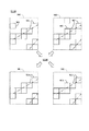
図6は、ステップS120による処理の具体例を説明するための図である。図6の上段には、破線の矩形により第1画像IM1の一部範囲と第2画像IM2の一部範囲とを夫々示している。また、図6の上段において、第1画像IM1内の複数の実線による小さい矩形はそれぞれ、ステップS110で第1画像IM1から皺候補領域として検出された矩形領域(W1)である。同様に、図6の上段において、第2画像IM2内の複数の実線による小さい矩形はそれぞれ、ステップS110で第2画像IM2から皺候補領域として検出された矩形領域(W2)である。 FIG. 6 is a diagram for explaining a specific example of the process according to step S120. In the upper part of FIG. 6, a partial range of the first image IM1 and a partial range of the second image IM2 are shown by a broken line rectangle, respectively. Further, in the upper part of FIG. 6, each of the small rectangles formed by the plurality of solid lines in the first image IM1 is a rectangular region (W1) detected as a wrinkle candidate region from the first image IM1 in step S110. Similarly, in the upper part of FIG. 6, the small rectangles formed by the plurality of solid lines in the second image IM2 are rectangular regions (W2) detected as wrinkle candidate regions from the second image IM2 in step S110, respectively.
図6の上段に示した第1画像IM1の一部範囲と第2画像IM2の一部範囲との関係は、原稿Pにおけるある範囲の表裏の関係に当たる。皺特定部21は、第1画像と第2画像との両方における同じ位置に皺候補領域が存在する場合、それら皺候補領域を皺領域として特定する。例えば、図6の上段に示した第1画像IM1内の右下隅の矩形領域W1の位置(原点O1を基準にした位置)と、図6の上段に示した第2画像IM2内の右下隅の矩形領域W2の位置(原点O2を基準にした位置)とは同じである。従って、これら右下隅の矩形領域W1,W2は、いずれも皺領域に特定される。つまり、皺特定部21は、図6の上段に示した第1画像IM1と、図6の上段に示した第2画像IM2とを比較し、同じ位置にある矩形領域W1,W2の組み合わせを全て皺領域に特定する。
The relationship between the partial range of the first image IM1 and the partial range of the second image IM2 shown in the upper part of FIG. 6 corresponds to the front-back relationship of a certain range in the document P. When the wrinkle candidate region exists at the same position in both the first image and the second image, the
図6においても、第1画像IM1、第2画像IM2それぞれに、2点鎖線による直線で皺(皺の一部分)の存在を例示している。図6に示した第1画像IM1内の長い皺と第2画像IM2内の長い皺は同じ皺である。同様に、図6に示した第1画像IM1内の短い皺と第2画像IM2内の短い皺は同じ皺である。 Also in FIG. 6, the existence of wrinkles (a part of wrinkles) is illustrated by a straight line formed by a two-dot chain line in each of the first image IM1 and the second image IM2. The long wrinkles in the first image IM1 and the long wrinkles in the second image IM2 shown in FIG. 6 are the same wrinkles. Similarly, the short wrinkles in the first image IM1 and the short wrinkles in the second image IM2 shown in FIG. 6 are the same wrinkles.
図6の下段には、ステップS120の結果、皺特定部21が皺領域に特定した各矩形領域を示している。つまり、図6の下段において、第1画像IM1内の複数の実線による小さい矩形はそれぞれ、ステップS120で皺領域に特定された矩形領域(W1s)である。同様に、図6の下段において、第2画像IM2内の複数の実線による小さい矩形はそれぞれ、ステップS120で皺領域に特定された矩形領域(W2s)である。図6の上段と下段とを比較すると判るように、第1画像IM1、第2画像IM2のどちらか一方だけに皺候補領域(矩形領域W1または矩形領域W2)が検出された位置は、皺領域に特定されない。この結果、原稿の第1面と第2面とのいずれか一方にのみ存在している、例えば、ゴミやオブジェクトの一部の模様等の、皺ではないが皺に類似しているものは皺領域として特定されず、実際の原稿の皺と重なる画像範囲が高精度に皺領域として特定される。
The lower part of FIG. 6 shows each rectangular area specified by the
ステップS130では、制御部11(皺処理部22)は、ステップS120で特定された皺領域を対象として皺除去処理を行う。なお、ステップS130で処理対象とする画像は、予め読取装置10に読取指示がされている面の画像である。ユーザーは、読取装置10による読取開始(搬送部13による原稿の搬送開始)に先立ち、図示しない操作部等を介して、読取装置10に原稿の片面読取又は両面読取を設定することができる。 In step S130, the control unit 11 (wrinkle processing unit 22) performs wrinkle removal processing on the wrinkle region specified in step S120. The image to be processed in step S130 is an image of a surface to which the reading device 10 has been instructed to read in advance. Prior to the start of scanning by the scanning device 10 (starting of transporting the document by the transport unit 13), the user can set the scanning device 10 to read one side or both sides of the document via an operation unit (not shown) or the like.
本実施形態では、制御部11は、原稿の片面読取が設定されている場合には、原稿の片面から読み取った画像(ここでは、第1面から読み取った第1画像)を対象としてステップS130以降の処理を実行するものとする。一方、制御部11は、原稿の両面読取が設定されている場合には、原稿の両面から読み取った画像、つまり第1面から読み取った第1画像および第2面から読み取った第2画像の夫々を対象としてステップS130以降の処理を実行する。ただし、これまでの説明から解るように、本実施形態では、片面読取と両面読取のいずれが設定されているかに関係なく、皺領域を特定するために、読取部12は原稿の両面を読み取り、制御部11は、読取部12から第1面の第1画像および第2面の第2画像を取得し(ステップS100)、ステップS110,S120を実行する。
In the present embodiment, when one-sided scanning of the document is set, the
第1画像を対象としてステップS130を実行する場合について説明する。この場合、ステップS130では、皺処理部22は、ステップS100で取得された第1画像(例えば、第1画像IM1(ただし背景板画像を除く))を処理対象とし、この第1画像IM1からステップS120で特定された皺領域の色(色の変動)を平坦化させる皺除去処理を行う。
A case where the step S130 is executed for the first image will be described. In this case, in step S130, the
図7は、皺除去処理の概念を説明するための図である。図7の上段には、グラフC1を示している。グラフC1の見方は、図5の下段に例示したグラフの見方と同じである。グラフC1は、ステップS120において第1画像IM1内で特定された1つの皺領域(矩形領域W1s)に上述のように設定された1つの走査線SLにおける画素の明るさの変動を例示している。皺処理部22は、このような明るさの変動を結果的に抑制するための画像処理(皺除去処理)を行う。具体的には、皺処理部22は、ステップS110で皺特定部21により明るさ変動領域と判定された走査線SL上の画素範囲(範囲Z)の、一端の画素の色情報と他端の色情報とを所定の色空間(例えば、RGB色空間や、L*a*b*色空間)内において直線で結び、当該所定の色空間内の当該直線上に並ぶ各色で、当該走査線SL上の画素範囲(範囲Z)の各画素の色を置換する。
FIG. 7 is a diagram for explaining the concept of the wrinkle removing process. Graph C1 is shown in the upper part of FIG. 7. The view of the graph C1 is the same as the view of the graph illustrated in the lower part of FIG. The graph C1 exemplifies the variation in the brightness of the pixels in one scanning line SL set as described above in one wrinkle region (rectangular region W1s) identified in the first image IM1 in step S120. .. The
図7の下段には、グラフC1が検出された走査線SLにおける画素の明るさの変動であって、上述の皺除去処理後の明るさの変動を実線で例示している。すなわち図7の下段に示すように、グラフC1は、皺除去処理により、明部および暗部を有していた状態からほぼ平坦な状態(明るさの凹凸がほぼ無い状態)となる。なお、ステップS110で皺特定部21により明るさ変動領域と判定された走査線SL上の画素範囲(範囲Z)の、一端の画素の色情報と他端の色情報とは、互いに近い色であることが多い。そのため、皺処理部22は、これら範囲Zの一端の画素の色情報と他端の色情報との平均の色情報により、当該範囲Zの各画素の色を置換してもよい。あるいは、より単純に、皺処理部22は、当該範囲Zの一端の画素の色情報と他端の色情報との何れか一方により、当該範囲Zの各画素の色を置換してもよい。第1画像を対象としたステップS130では、皺処理部22は、第1画像IM1からステップS120で特定された全ての皺領域(矩形領域W1s)を夫々対象として、上述の走査線SL(明るさ変動領域を含むと判別された走査線SL)毎の皺除去処理を実行する。
In the lower part of FIG. 7, the variation in the brightness of the pixels in the scanning line SL in which the graph C1 is detected is illustrated by a solid line, and the variation in the brightness after the above-mentioned wrinkle removal treatment is illustrated. That is, as shown in the lower part of FIG. 7, the graph C1 is changed from a state having a bright part and a dark part to a substantially flat state (a state where there is almost no unevenness in brightness) by the wrinkle removing process. The color information of the pixel at one end and the color information at the other end of the pixel range (range Z) on the scanning line SL determined to be the brightness fluctuation region by the
第2画像を対象としてステップS130を実行する場合についても説明する。この場合、ステップS130では、皺処理部22は、ステップS100で取得された第2画像(例えば、第2画像IM2(ただし背景板画像を除く))も処理対象とし、第2画像2からステップS120で特定された皺領域の色(色の変動)を平坦化させる皺除去処理を行う。
A case where the step S130 is executed for the second image will also be described. In this case, in step S130, the
図7の上段には、グラフC2を示している。グラフC2の見方は、図5の下段に例示したグラフやグラフC1の見方と同じである。グラフC2は、ステップS120において第2画像IM2内で特定された1つの皺領域(矩形領域W2s)に上述のように設定された1つの走査線SLにおける画素の明るさの変動を例示している。皺処理部22は、このような明るさの変動を結果的に抑制するための画像処理(皺除去処理)を行う。皺除去処理の具体的方法は、グラフC1に関して説明した通りである。
Graph C2 is shown in the upper part of FIG. 7. The view of the graph C2 is the same as the view of the graph and the graph C1 illustrated in the lower part of FIG. Graph C2 illustrates the variation in pixel brightness in one scanning line SL set as described above in one wrinkle region (rectangular region W2s) identified in the second image IM2 in step S120. .. The
図7の下段には、グラフC2が検出された走査線SLにおける画素の明るさの変動であって皺除去処理後の明るさの変動を実線で例示している。すなわち図7の下段に示すように、グラフC2は、皺除去処理により、明部および暗部を有していた状態からほぼ平坦な状態(明るさの凹凸がほぼ無い状態)となる。ステップS130では、第1画像を対象とした処理と同様に、皺処理部22は、第2画像(第2画像IM2)からステップS120で特定された全ての皺領域(矩形領域W2s)を夫々対象として、上述の走査線SL(明るさ変動領域を含むと判別された走査線SL)毎の皺除去処理を実行する。
In the lower part of FIG. 7, the variation in the brightness of the pixels in the scanning line SL in which the graph C2 is detected, and the variation in the brightness after the wrinkle removal process is illustrated by a solid line. That is, as shown in the lower part of FIG. 7, the graph C2 is changed from a state having a bright part and a dark part to a substantially flat state (a state where there is almost no unevenness in brightness) by the wrinkle removing process. In step S130, the
ステップS140では、制御部11(画像出力部23)が、ステップS130による皺除去処理が施された画像に、背景板画像を削除し原稿の画像を残す切出処理などの画像処理を行い、画像処理後の画像を出力して、図4のフローチャートを終える。上述したように、原稿の片面読取が設定されている場合には、ステップS130では第1画像が皺除去処理の対象となっているため、ステップS140では、画像出力部23は、ステップS130を経た第1画像を出力することになる。一方、原稿の両面読取が設定されている場合には、ステップS130では第1画像および第2画像が夫々に皺除去処理の対象となっているため、ステップS140では、画像出力部23は、ステップS130を経た第1画像および第2画像を出力することになる。
In step S140, the control unit 11 (image output unit 23) performs image processing such as cutting processing to delete the background plate image and leave the image of the original on the image subjected to the wrinkle removal processing in step S130, and then perform the image processing. The processed image is output, and the flowchart of FIG. 4 ends. As described above, when single-sided scanning of the original is set, the first image is the target of the wrinkle removing process in step S130. Therefore, in step S140, the
画像出力部23による画像の出力先は種々考えられる。例えば、読取装置10内への読取画像の保存をユーザーから予め指示されている場合には、画像出力部23は、ステップS140では、出力対象の画像を記憶部15に出力して記憶部15に記憶させる。また、例えば、読取装置10外の所定のPCやFAX機への読取画像の保存をユーザーから予め指示されている場合には、画像出力部23は、ステップS140では、出力対象の画像を、通信IF14を介して外部の前記PC又はFAX機へ転送する。また、例えば、原稿のコピーをユーザーから予め指示されている場合には、画像出力部23は、ステップS140では、出力対象の画像を、不図示の印刷機構へ出力して、出力対象の画像の印刷を印刷機構に実行させる。
Various output destinations of the image by the
このように本実施形態によれば、読取装置10は、原稿の第1面と第1面の裏側の第2面とを読み取ることにより第1面の読取画像である第1画像と第2面の読取画像である第2画像とを生成する読取部12を備える。そして、画像取得部20は、第1画像および第2画像を取得し(取得工程)、皺特定部21は、第1画像と第2画像との両方における同じ位置に、明るさが凸状に変化する明部と当該明部と接して明るさが凹状に変化する暗部とを有する明るさ変動領域が存在する場合に、この明るさ変動領域(明るさ変動領域を有する皺候補領域)を皺領域に特定し(特定工程)、皺処理部22および出力部23は、皺領域に対する画像処理(皺除去処理)を施した第1画像を(少なくとも)出力する(出力工程)。
As described above, according to the present embodiment, the reading device 10 reads the first surface of the document and the second surface on the back side of the first surface to read the first image and the second surface, which are the scanned images of the first surface. A
つまり読取装置10は、明るさが凸状に変化する明部と当該明部と接して明るさが凹状に変化する暗部とを有する明るさ変動領域という、明るさに所定の変動パターンが見られる領域を皺候補領域とし、原稿の表裏に皺候補領域を有する位置を皺領域に特定する。例えば、図7の上段に示すように、グラフC1は、グラフC2が検出された矩形領域Wよりも相対的に明るい矩形領域Wから検出されたと言えるが、本実施形態では、このようなグラフC1,C2のいずれも、明るさ変動領域に該当すると判別する。これにより、原稿の第1面(第1画像)が第2面(第2画像)と比べて全体的に明るい(あるいは暗い)といったように、第1面(第1画像)と第2面(第2画像)とに色や濃度の違いがあったとしても、原稿の読取画像から精度よく皺を特定することができる。 That is, in the reading device 10, a predetermined variation pattern in brightness can be seen, which is a brightness variation region having a bright portion in which the brightness changes in a convex shape and a dark portion in which the brightness changes in a concave shape in contact with the bright portion. The area is defined as a wrinkle candidate area, and the position where the wrinkle candidate area is located on the front and back of the document is specified as the wrinkle area. For example, as shown in the upper part of FIG. 7, it can be said that the graph C1 is detected in the rectangular area W which is relatively brighter than the rectangular area W in which the graph C2 is detected. , C2 are all determined to correspond to the brightness fluctuation region. As a result, the first surface (first image) and the second surface (first image) of the document are brighter (or darker) as a whole than the second surface (second image). Even if there is a difference in color and density from the second image), wrinkles can be accurately identified from the scanned image of the original.
ここで、ステップS120の処理について、図6を参照して説明を捕捉する。
例えば、皺特定部21は、第1画像IM1と第2画像IM2との同じ位置のいずれからも皺候補領域を検出した場合であっても、当該同じ位置の第1画像IM1側、第2画像IM2側それぞれの皺候補領域における明部と暗部との範囲の比率が所定差以上に異なる場合には、当該同じ位置の第1画像IM1側および第2画像IM2側の皺候補領域を皺領域として特定しない、としてもよい。明部と暗部との比率とは、図5の下段に例示したグラフを例に採ると、明るさ変動領域(範囲Z)における範囲Z1の長さ(画素数)と範囲Z2の長さ(画素数)との比率である。つまり、同じ位置の第1画像IM1側、第2画像IM2側それぞれで皺候補領域が検出できたとしても、第1画像IM1側の明部と暗部との範囲の比率と、第2画像IM2側の明部と暗部との範囲の比率とが所定差以上に異なる場合には、第1面F1側と第2面F2側とで互いに無関係の皺に似た画像を偶然に皺候補領域として検出したと推定できるため、皺特定部21は、これら皺候補領域を皺領域として特定しない。
また、皺特定部21は、第1画像IM1と第2画像IM2との同じ位置のいずれからも皺候補領域を検出した場合であっても、当該同じ位置の第1画像IM1側、第2画像IM2側それぞれの皺候補領域における明部と暗部との順番が異なる場合には、当該同じ位置の第1画像IM1側および第2画像IM2側の皺候補領域を皺領域として特定しない、としてもよい。これは例えば、明るさ変動領域(範囲Z)において、一方の面では図5の下段のように左側に明部があり右側に暗部があるが、他方の面では右側に明部があり左側に暗部があるというような場合には、原稿の同じ位置で表側に凸であり裏側にも凸であるというような状況は通常ありえないため、第1面F1側と第2面F2側とで互いに無関係の皺に似た画像を偶然に皺候補領域として検出したと推定できる。そのため、皺特定部21は、これら皺候補領域を皺領域として特定しない。
Here, the description of the process of step S120 will be captured with reference to FIG.
For example, even if the
Further, even when the wrinkle candidate region is detected from any of the same positions of the first image IM1 and the second image IM2, the
また、皺特定部21は、第1画像IM1と第2画像IM2との同じ位置のいずれからも皺候補領域を検出した場合であっても、当該同じ位置の第1画像IM1側、第2画像IM2側それぞれの皺候補領域における明るさ変動領域の向きが異なる場合には、当該同じ位置の第1画像IM1側および第2画像IM2側の皺候補領域を皺領域として特定しない。明るさ変動領域の向きとは、当該明るさ変動領域が存在すると判定されたときの走査線SLの向きである。同じ位置の第1画像IM1側、第2画像IM2側それぞれで皺候補領域が検出できたとしても、それら皺候補領域がそれぞれに含む明るさ変動領域の向きが、一方の皺候補領域は画像の縦方向のみで、他方の皺候補領域が画像の横方向のみである場合には、第1面F1側と第2面F2側とで互いに無関係の皺に似た画像を偶然に皺候補領域として検出したと推定できるため、皺特定部21は、これら皺候補領域を皺領域として特定しない。
Further, even when the wrinkle candidate region is detected from any of the same positions of the first image IM1 and the second image IM2, the
3.変形例:
本実施形態は上述の態様に限定されず種々の態様を含む。以下では、本実施形態の変形例を説明する。変形例に関しては、これまでに説明した実施形態と異なる点について説明する。
3. 3. Modification example:
The present embodiment is not limited to the above-mentioned embodiment, but includes various embodiments. Hereinafter, a modified example of the present embodiment will be described. Regarding the modified example, the points different from the embodiments described so far will be described.
図8は、ステップS120による処理の具体例であって図6とは異なる状況を説明するための図である。図8の見方は、図6の見方と同じである。図8の上段において、第1画像IM1内の複数の実線による小さい矩形はそれぞれ、ステップS110で第1画像IM1から皺候補領域として検出された矩形領域(W1)であり、第1画像IM1内の複数の1点鎖線による小さい矩形はそれぞれ、ステップS110で第1画像IM1から皺候補領域として検出されなかった矩形領域(非皺候補領域)の一部である。また、図8の上段において、第2画像IM2内の複数の実線による小さい矩形はそれぞれ、ステップS110で第2画像IM2から皺候補領域として検出された矩形領域(W2)である。 FIG. 8 is a diagram for explaining a situation different from that of FIG. 6, which is a specific example of the process according to step S120. The view of FIG. 8 is the same as the view of FIG. In the upper part of FIG. 8, the small rectangles formed by the plurality of solid lines in the first image IM1 are rectangular regions (W1) detected as wrinkle candidate regions from the first image IM1 in step S110, respectively, and are in the first image IM1. Each of the small rectangles formed by the plurality of one-point chain lines is a part of a rectangular region (non-wrinkle candidate region) that was not detected as a wrinkle candidate region from the first image IM1 in step S110. Further, in the upper part of FIG. 8, each of the small rectangles formed by the plurality of solid lines in the second image IM2 is a rectangular area (W2) detected as a wrinkle candidate region from the second image IM2 in step S110.
図8の例では、第1画像IM1には文字(例えば、数字の「0」)が含まれており、1点鎖線で示す非皺候補領域は、当該文字の一部分と重なっている。言い換えると、ステップS110では、皺特定部21は、文字と重なる位置に設定した矩形領域Wにおける走査線SLからは、当該文字の影響により、明るさ変動領域が存在しないと判定し、このように当該文字の影響により明るさ変動領域が存在しないと判定した矩形領域Wが、図8の1点鎖線で示す非皺候補領域である。
In the example of FIG. 8, the first image IM1 contains a character (for example, the number “0”), and the non-wrinkle candidate region indicated by the alternate long and short dash line overlaps a part of the character. In other words, in step S110, the
図9の上段には、上述のように文字の影響により明るさ変動領域が存在しないと判定された矩形領域Wに設定した1つの走査線SL上の画素毎の明るさの変動の様子を、実線のグラフにより例示している。当該グラフの見方は、図5の下段に例示したグラフ等と同じである。図9の上段に示したグラフにおいては、文字「0」のいわゆるエッジに該当するエッジ画素の位置で、明るさがほぼ垂直に変化しており、当該文字に該当する範囲では明るさは一定値(例えば、黒に相当する最も暗い値)で安定している(明るさがほぼ変化しない)。ステップS110では、皺特定部21は、走査線SLについて明るさ変動領域の存否を判定する際、文字のエッジに特徴的なエッジ画素の存在やエッジ画素に挟まれて一定値で明るさが変化しない範囲の存在を検知した場合には、明るさ変動領域に該当しないと判定する。ちなみに図9の上段のグラフにおいては、文字「0」が存在しないと仮定した場合の明るさの変動を破線で示している。つまり、図8の上段の1点鎖線で示す非皺候補領域は、皺(第1画像IM1内の2点鎖線)と重なっているため、本来であれば皺候補領域と判定されるべきであるが、文字「0」の存在により皺候補領域と判定されなかった。
In the upper part of FIG. 9, the state of the brightness fluctuation for each pixel on one scanning line SL set in the rectangular region W where it is determined that the brightness fluctuation region does not exist due to the influence of the characters as described above is shown. It is illustrated by a solid line graph. The way of reading the graph is the same as the graph and the like illustrated in the lower part of FIG. In the graph shown in the upper part of FIG. 9, the brightness changes almost vertically at the position of the edge pixel corresponding to the so-called edge of the character "0", and the brightness is a constant value in the range corresponding to the character. Stable at (for example, the darkest value corresponding to black) (brightness is almost unchanged). In step S110, when the
ここで、図8の上段の第2画像IM2における矩形領域W2のうち、太線で示した矩形領域W2に注目する。当該太線で示した矩形領域W2は、ステップS110で第2画像IM2から皺候補領域として検出された領域であるが、これと同じ位置の第1画像IM1側の領域が上述の非皺候補領域に該当している。当該太線で示した矩形領域W2のようなステップS110で検出された皺候補領域と当該皺候補領域が検出された画像(第1画像または第2画像)の裏側の画像の同じ位置の非皺候補領域を、便宜上、片側皺候補領域と呼ぶ。 Here, of the rectangular area W2 in the second image IM2 in the upper part of FIG. 8, attention is paid to the rectangular area W2 shown by the thick line. The rectangular region W2 shown by the thick line is a region detected as a wrinkle candidate region from the second image IM2 in step S110, but the region on the first image IM1 side at the same position as the above-mentioned non-wrinkle candidate region. Applicable. The wrinkle candidate region detected in step S110 such as the rectangular region W2 shown by the thick line and the non-wrinkle candidate at the same position on the back side image of the image (first image or second image) in which the wrinkle candidate region is detected. The region is referred to as a one-sided wrinkle candidate region for convenience.
これまでの説明によれば、片側皺候補領域はステップS120で皺領域として特定されない。しかし当該変形例のステップS120では、皺特定部21は、片側皺候補領域について、以下の所定条件を満たす場合に皺領域として特定する。
According to the description so far, the one-sided wrinkle candidate region is not specified as a wrinkle region in step S120. However, in step S120 of the modification, the
条件1:片側皺候補領域が、皺候補領域が検出された画像内において他の皺領域と連続していること。
条件2:片側皺候補領域が、皺候補領域が検出されなかった画像内において他の皺領域と連続していること。
Condition 1: The one-sided wrinkle candidate region is continuous with the other wrinkle region in the image in which the wrinkle candidate region is detected.
Condition 2: The one-sided wrinkle candidate region is continuous with the other wrinkle region in the image in which the wrinkle candidate region is not detected.
ここで、図8の上段の第2画像IM2における太線で示した2つの矩形領域W2のうち、右側の矩形領域W2(片側皺候補領域)を第1注目領域W2aと呼び、先ず第1注目領域W2aについて、条件1,2が成立するか否かを具体的に検討する。
条件1の片側皺候補領域が、皺候補領域が検出された画像内において他の皺領域と連続するとは、例えば、当該片側皺候補領域の上、下、左、右、右上、右下、左下、左上の8個の隣接領域のうち少なくとも2個以上の隣接領域に皺領域が存在し、かつ、当該片側皺候補領域を挟んだ両側(当該片側皺候補領域よりも右側と左側、または当該片側皺候補領域よりも上側と下側)の隣接領域に皺領域が存在していることを言うとする。図8によれば、第1注目領域W2aは、第2画像IM2において他の皺領域と連続していると言えるため、条件1を満たす。
Here, of the two rectangular regions W2 shown by the thick line in the second image IM2 in the upper part of FIG. 8, the rectangular region W2 (one-sided wrinkle candidate region) on the right side is called the first attention region W2a, and the first attention region is first. For W2a, whether or not
The fact that the one-sided wrinkle candidate region of
条件2の片側皺候補領域が、皺候補領域が検出されなかった画像内において他の皺領域と連続するとは、例えば、当該片側皺候補領域の上、下、左、右、右上、右下、左下、左上の8個の隣接領域のうち少なくとも2個以上の隣接領域に皺領域が存在していることを言うとする。図8によれば、第1注目領域W2aと同一位置の第1画像IM1側の領域(図8の上段において1点鎖線で示した2つの非皺候補領域のうちの右側の非皺候補領域W3a)は、第1画像IM1において他の皺領域と連続していると言え、そのため、第1注目領域W2aは条件2も満たす。 The condition 2 that the one-sided wrinkle candidate region is continuous with the other wrinkle region in the image in which the wrinkle candidate region is not detected is, for example, above, below, left, right, upper right, lower right, etc. It is assumed that a wrinkled region exists in at least two or more adjacent regions among the eight adjacent regions in the lower left and upper left. According to FIG. 8, the region on the first image IM1 side at the same position as the first attention region W2a (the non-wrinkle candidate region W3a on the right side of the two non-wrinkle candidate regions shown by the alternate long and short dash line in the upper part of FIG. 8). ) Can be said to be continuous with other wrinkle regions in the first image IM1. Therefore, the first attention region W2a also satisfies the condition 2.
このように条件1および条件2を満たす第1注目領域W2aについて、皺特定部21は皺領域に特定する。また、1つの皺が原稿の第1面と第2面のいずれか一方にのみ表出していることは通常考えられないため、皺特定部21は、片側皺候補領域に該当する皺候補領域を皺領域に特定した場合には、当該皺候補領域が検出された画像の裏側の画像の同じ位置の領域(非皺候補領域)についても皺領域に特定する。従って図8の例では、第2画像IM2における第1注目領域W2aと、この第1注目領域W2aと同一位置の第1画像IM1側の非皺候補領域W3aとはいずれも皺領域に特定される(図8の下段参照)。
As described above, the
次に、図8の上段の第2画像IM2における太線で示した2つの矩形領域W2のうち左側の矩形領域W2(片側皺候補領域)を第2注目領域W2bと呼び、第2注目領域W2bについて、条件1,2が成立するか否かを検討する。上述したように第1注目領域W2a(および第1注目領域W2aと同一位置の第1画像IM1側の非皺候補領域W3a)は皺領域に特定された。従って、図8によれば、第2注目領域W2bは、第2画像IM2において他の皺領域と連続していると言え、条件1を満たす。また、図8によれば、第2注目領域W2bと同一位置の非皺候補領域(図8の上段において1点鎖線で示した2つの非皺候補領域のうちの左側の非皺候補領域W3b)は、第1画像IM1において他の皺領域と連続していると言え、そのため第2注目領域W2bは条件2も満たす。条件1および条件2を満たす第2注目領域W2bについて、皺特定部21は皺領域に特定する。従って図8の例では、第2画像IM2における第2注目領域W2bと、この第2注目領域W2bと同一位置の第1画像IM1側の非皺候補領域W3bとはいずれも皺領域に特定される(図8の下段参照)。
Next, of the two rectangular regions W2 shown by the thick line in the second image IM2 in the upper part of FIG. 8, the rectangular region W2 (one-sided wrinkle candidate region) on the left side is called the second attention region W2b, and the second attention region W2b , Examine whether
ただし、画像内に表現された文字が複数の矩形領域Wにまたがることで複数の矩形領域Wが連続して非皺候補領域と判定されてしまう可能性を考えると、皺特定部21は、条件1を下記の条件1´に変更し、条件2を下記の条件2´に変更して、片側皺候補領域について皺領域に特定できるかを判断してもよい。
条件1´:片側皺候補領域が、皺候補領域が検出された画像内において他の皺領域又は他の片側皺候補領域と連続していること。
条件2´:片側皺候補領域が、皺候補領域が検出されなかった画像内において、他の片側皺候補領域と連続している場合には、連続する他の片側皺候補領域をたどると皺領域に至ること。
なお当該変形例では、処理を簡易化するために条件1又は条件1´のみを採用してもよい。つまりステップS120では、皺特定部21は、片側皺候補領域について条件1又は条件1´を満たす場合に表裏ともに皺領域に特定する、としてもよい。
However, considering the possibility that the characters expressed in the image straddle the plurality of rectangular areas W and the plurality of rectangular areas W are continuously determined as non-wrinkle candidate areas, the
Condition 1': The one-sided wrinkle candidate region is continuous with another wrinkle region or another one-sided wrinkle candidate region in the image in which the wrinkle candidate region is detected.
Condition 2': If the one-sided wrinkle candidate region is continuous with another one-sided wrinkle candidate region in the image in which the wrinkle candidate region is not detected, the wrinkle region is traced to the continuous other one-sided wrinkle candidate region. To reach.
In the modified example,
このような変形例によれば、皺特定部21は、同じ位置において第1画像と第2画像との一方にのみ明るさ変動領域(明るさ変動領域を有する皺候補領域)が存在する場合に、当該一方に存在する明るさ変動領域が皺領域に特定した他の領域と連続していれば、当該一方に存在する明るさ変動領域を皺領域に特定する。原稿における皺は、ごく短い範囲に局所的に発生しているというよりは、ある程度の長さをもって発生していることが通常である。そこで、第1画像と第2画像との両方における同じ位置で皺候補領域に該当するという条件を満たさない皺候補領域(片側皺候補領域)についても、近隣の皺領域との関係性、つまり皺の連続性を考慮することで、皺領域として特定することができる。これにより、第1画像と第2画像との同じ位置のうち、一方には明るさ変動領域が存在するが、他方には文字等の存在に起因して明るさ変動領域が存在すると判別できない場合であっても、高い精度で原稿の皺を特定する(皺の検出漏れを防ぐ)ことができる。
According to such a modification, the
当該変形例におけるステップS130でも、皺処理部22は、予め読取装置10に読取指示がされている面の画像を対象として皺除去処理を実行する。
先ず、第1画像、具体的には図8の下段に示した第1画像IM1を対象としてステップS130を実行する場合について説明する。ステップS130では、皺処理部22は、第1画像F1からステップS120で特定された全ての皺領域(矩形領域W1s)を夫々対象として、色を平坦化させる皺除去処理を行う。この場合、ステップS110で皺候補領域として検出され、ステップS120で皺領域に特定された領域(当該変形例で皺領域に特定した片側皺候補領域を含む。)の色の平坦化に関しては、図7等を参照して既に説明した通りの処理を実行すればよい。一方、ステップS110で皺候補領域として検出されず(つまり非皺候補領域とされ)、その後のステップS120で、当該変形例で説明したように皺領域に特定した領域(非皺候補領域W3a,W3b)に関しては、皺処理部22は、第1画像IM1内に表現されたオブジェクト(図8の例では、文字「0」)のエッジの外側の色を平坦化させる皺除去処理を実行する。
Also in step S130 in the modification, the
First, a case where step S130 is executed for the first image, specifically, the first image IM1 shown in the lower part of FIG. 8 will be described. In step S130, the
図9は、当該変形例においてオブジェクトのエッジの外側の色を平坦化させる皺除去処理の概念を説明するための図でもある。皺処理部22は、図9の上段に示すような明るさの変動のうちオブジェクトに該当しない範囲の明るさの変動を結果的に抑制するための画像処理(皺除去処理)を行う。この場合、皺処理部22は、上述のようにステップS120で片側皺候補領域としての皺候補領域を皺領域に特定したことに伴い皺領域に特定した非皺候補領域(矩形領域)において、走査線SL上で、文字等のエッジに該当するエッジ画素を特定し、この特定したエッジ画素で挟まれた範囲(明るさが一定である範囲)を非処理範囲とする。そして、当該走査線SL上の当該非処理範囲の外側であって明るさの変動率(明るさの変動を示すグラフの傾き)が所定傾きよりも急である範囲の明るさを一定値とするように各画素の色を置換する。具体的には、例えば当該走査線SL上の非処理範囲の外側であって明るさの変動率が所定傾きよりも急である範囲の画素の色を、当該明るさの変動率が所定傾きよりも急である範囲よりも外側の画素の色と同じ色に置換する。
FIG. 9 is also a diagram for explaining the concept of the wrinkle removing process for flattening the color outside the edge of the object in the modification. The
図9の下段には、図9の上段に示したグラフが検出された走査線SLにおける画素の明るさの変動であって、当該変形例においてオブジェクトのエッジの外側の色を平坦化させる皺除去処理後の明るさの変動を、実線で例示している。すなわち図9の下段に示すようにグラフは皺除去処理により、文字に該当しない画素範囲の明るさがほぼ平坦な状態となる。 In the lower part of FIG. 9, the graph shown in the upper part of FIG. 9 is the fluctuation of the brightness of the pixel in the detected scanning line SL, and the wrinkle removal that flattens the color outside the edge of the object in the modification. The fluctuation of brightness after processing is illustrated by a solid line. That is, as shown in the lower part of FIG. 9, the graph is in a state where the brightness of the pixel range not corresponding to the character is almost flat due to the wrinkle removal process.
第2画像(図8の下段に示した第2画像IM2)を対象としてステップS130を実行する場合について説明する。この場合、ステップS110で皺候補領域に検出され、ステップS120で皺領域に特定された領域(当該変形例で皺領域に特定した片側皺候補領域を含む。)の色の平坦化に関して、皺処理部22は、図7等を参照して既に説明した通りの処理を実行すればよい。
A case where step S130 is executed for the second image (second image IM2 shown in the lower part of FIG. 8) will be described. In this case, wrinkle treatment is performed for flattening the color of the region detected in the wrinkle candidate region in step S110 and specified as the wrinkle region in step S120 (including the one-sided wrinkle candidate region specified as the wrinkle region in the modification). The
このような変形例にかかるステップS130およびその後のS140によれば、出力部(皺処理部22および出力部23)は、第1画像と第2画像との同じ位置において第2画像にのみ明るさ変動領域(明るさ変動領域を有する皺候補領域)が存在し、当該第2画像に存在する明るさ変動領域が皺領域に特定された場合、当該第2画像で特定された皺領域の裏の第1画像側の領域(非皺候補領域W3a,W3b)を対象として、第1画像内に表現されたオブジェクト(図8の例では文字「0」)のエッジの外側の色を平坦化させる画像処理を施した第1画像を出力する。当該構成によれば、皺の存在が除去された第1画像を出力することができる。また、当該構成によれば第1画像において皺とオブジェクトが重なっている場合には、オブジェクトの色は保持しつつオブジェクトと交差する皺についてその存在をオブジェクトのエッジ間際まで的確に除去することができる。
According to step S130 and subsequent S140 relating to such a modification, the output unit (
図8では、第1画像IM1側にオブジェクトとしての文字「0」が含まれている場合を例示したが、第2画像IM2側にこのようなオブジェクトが含まれていることも当然ある。その場合には、第1画像IM1内の皺候補領域(矩形領域W1)の中にも、上述したような片側皺候補領域に該当するものが含まれることがある。従って、当該変形例にかかるステップS130およびその後のS140によれば、出力部(皺処理部22および出力部23)は、第1画像と第2画像との同じ位置において第1画像にのみ明るさ変動領域(明るさ変動領域を有する皺候補領域)が存在し、当該第1画像に存在する明るさ変動領域が皺領域に特定された場合、当該第1画像で特定された皺領域の色を平坦化させる画像処理を施した第1画像を出力する、とも言える。
In FIG. 8, the case where the character “0” as an object is included on the first image IM1 side is illustrated, but it is natural that such an object is included on the second image IM2 side. In that case, the wrinkle candidate region (rectangular region W1) in the first image IM1 may also include a wrinkle candidate region as described above. Therefore, according to step S130 and subsequent S140 according to the modification, the output unit (
本実施形態や変形例において、皺処理部22がステップS130において実行する画像処理は、皺領域の色を平坦化させる処理に限定されない。皺処理部22は、第1画像や第2画像においてステップS120で特定された皺領域内の皺が結果的に目立たない(ユーザーに視認され難い)ようにする画像処理を実行すればよいため、色を平坦にするという概念から外れる処理を実行してもよい。また、皺処理部22は、ステップS130において、ステップS120で特定された皺領域以外の領域に対する画像処理や、皺領域および皺領域以外の領域に対する画像処理を実行することで結果的に皺が目立たないようにしてもよい。
In the present embodiment and modifications, the image processing performed by the
また、皺処理(皺候補領域の検出から皺除去まで)を含む画像処理をどのような順番で行うかはプログラムAの設計において任意に決めることができるし、皺処理を含む画像処理の全部を読取装置10内で実行してもよいし、画像処理の一部又は全部を出力先のPC等の他の装置で実行させてもよい。すなわち、PCにインストールされたスキャンアプリケーションが読取装置10から第1画像と第2画像とを取得して、ステップS110以降の処理を実行してもよい。 Further, the order in which the image processing including the wrinkle processing (from the detection of the wrinkle candidate region to the removal of the wrinkles) is performed can be arbitrarily determined in the design of the program A, and the entire image processing including the wrinkle processing can be performed. It may be executed in the reading device 10, or a part or all of the image processing may be executed by another device such as a PC at the output destination. That is, the scanning application installed on the PC may acquire the first image and the second image from the reading device 10 and execute the processing after step S110.
また、皺候補領域の検出と皺領域の特定は、ステップS100で取得した第1画像および第2画像から解像度や階調数を減少させたモノクロの解析用画像を用いて行い、特定された皺領域の情報を用いて元の解像度や階調数のカラー画像(ステップS100で取得した第1画像や第2画像)に対して皺除去処理を行う構成であってもよい。 Further, the detection of the wrinkle candidate region and the identification of the wrinkle region are performed using a monochrome analysis image in which the resolution and the number of gradations are reduced from the first image and the second image acquired in step S100, and the identified wrinkles are identified. A wrinkle removing process may be performed on a color image (first image or second image acquired in step S100) having the original resolution and the number of gradations using the information of the region.
10…読取装置、11…制御部、12…読取部、13…搬送部、14…通信IF、15…記憶部、20…画像取得部、21…皺特定部、22…皺処理部、23…画像出力部、30…第1読取部、40…第2読取部、A…プログラム、P…原稿 10 ... reading device, 11 ... control unit, 12 ... reading unit, 13 ... transport unit, 14 ... communication IF, 15 ... storage unit, 20 ... image acquisition unit, 21 ... wrinkle identification unit, 22 ... wrinkle processing unit, 23 ... Image output unit, 30 ... 1st reading unit, 40 ... 2nd reading unit, A ... program, P ... original
Claims (5)
生成された前記第1画像と前記第2画像との両方における同じ位置に、明るさが凸状に変化する明部と前記明部と接して明るさが凹状に変化する暗部とを有する明るさ変動領域が存在する場合に、前記明るさ変動領域を皺領域に特定する特定部と、
特定された前記皺領域に対する画像処理を施した前記第1画像を出力する出力部と、を備え、
さらに前記特定部は、前記同じ位置において前記第1画像と前記第2画像との一方にのみ前記明るさ変動領域が存在していて、当該一方に存在する前記明るさ変動領域が前記皺領域に特定した他の領域と連続している場合に、当該一方に存在する前記明るさ変動領域を前記皺領域に特定する、ことを特徴とする読取装置。 By reading the first surface of the document and the second surface on the back side of the first surface, a first image which is a scanned image of the first surface and a second image which is a scanned image of the second surface are generated. With the reader
Brightness having a bright portion in which the brightness changes in a convex shape and a dark portion in which the brightness changes in a concave shape in contact with the bright portion at the same position in both the generated first image and the second image. When there is a fluctuation region, a specific part that specifies the brightness fluctuation region as a wrinkle region, and
An output unit for outputting the first image obtained by performing image processing on the specified wrinkle region is provided .
Further, in the specific portion, the brightness fluctuation region exists only in one of the first image and the second image at the same position, and the brightness fluctuation region existing in the one side is in the wrinkle region. A reading device characterized in that when it is continuous with another specified region, the brightness fluctuation region existing in one of the specified regions is specified as the wrinkle region.
前記同じ位置において前記第1画像にのみ前記明るさ変動領域が存在し、当該第1画像に存在する前記明るさ変動領域が前記皺領域に特定された場合、当該第1画像で特定された前記皺領域の色を平坦化させる画像処理を施した前記第1画像を出力し、
前記同じ位置において前記第2画像にのみ前記明るさ変動領域が存在し、当該第2画像に存在する前記明るさ変動領域が前記皺領域に特定された場合、当該第2画像で特定された前記皺領域の裏の前記第1画像側の領域を対象として、前記第1画像内に表現されたオブジェクトのエッジの外側の色を平坦化させる画像処理を施した前記第1画像を出力する、ことを特徴とする請求項1に記載の読取装置。 The output unit is
When the brightness fluctuation region exists only in the first image at the same position and the brightness fluctuation region existing in the first image is specified in the wrinkle region, the said-mentioned specified in the first image. The first image subjected to image processing for flattening the color of the wrinkle region is output.
When the brightness fluctuation region exists only in the second image at the same position and the brightness fluctuation region existing in the second image is specified in the wrinkle region, the said is specified in the second image. To output the first image subjected to image processing for flattening the color outside the edge of the object expressed in the first image, targeting the area on the first image side behind the wrinkle region. The reading device according to claim 1.
原稿の第1面と前記第1面の裏側の第2面との読み取りにより生成された前記第1面の読取画像である第1画像と前記第2面の読取画像である第2画像とを取得する取得機能と、
取得された前記第1画像と前記第2画像との両方における同じ位置に、明るさが凸状に変化する明部と前記明部と接して明るさが凹状に変化する暗部とを有する明るさ変動領域が存在する場合に、前記明るさ変動領域を皺領域に特定する特定機能と、
特定された前記皺領域に対する画像処理を施した前記第1画像を出力する出力機能と、をコンピューターに実行させ、
さらに前記特定機能は、前記同じ位置において前記第1画像と前記第2画像との一方にのみ前記明るさ変動領域が存在していて、当該一方に存在する前記明るさ変動領域が前記皺領域に特定した他の領域と連続している場合に、当該一方に存在する前記明るさ変動領域を前記皺領域に特定する、ことを特徴とする画像処理プログラム。 An image processing program
The first image, which is the scanned image of the first surface, and the second image, which is the scanned image of the second surface, generated by scanning the first surface of the document and the second surface on the back side of the first surface are combined. The acquisition function to acquire and
Brightness having a bright portion in which the brightness changes in a convex shape and a dark portion in which the brightness changes in a concave shape in contact with the bright portion at the same position in both the acquired first image and the second image. When there is a fluctuation region, the specific function to specify the brightness fluctuation region as a wrinkle region and
A computer is made to execute an output function for outputting the first image obtained by performing image processing on the specified wrinkle area .
Further, in the specific function, the brightness fluctuation region exists only in one of the first image and the second image at the same position, and the brightness fluctuation region existing in the one side is in the wrinkle region. An image processing program characterized in that when it is continuous with another specified region, the brightness fluctuation region existing in one of the specified regions is specified as the wrinkle region.
取得された前記第1画像と前記第2画像との両方における同じ位置に、明るさが凸状に変化する明部と前記明部と接して明るさが凹状に変化する暗部とを有する明るさ変動領域が存在する場合に、前記明るさ変動領域を皺領域に特定する特定工程と、
特定された前記皺領域に対する画像処理を施した前記第1画像を生産して出力する出力工程と、を備え、
さらに前記特定工程は、前記同じ位置において前記第1画像と前記第2画像との一方にのみ前記明るさ変動領域が存在していて、当該一方に存在する前記明るさ変動領域が前記皺領域に特定した他の領域と連続している場合に、当該一方に存在する前記明るさ変動領域を前記皺領域に特定する、ことを特徴とする画像生産方法。 The first image, which is the scanned image of the first surface, and the second image, which is the scanned image of the second surface, generated by scanning the first surface of the document and the second surface on the back side of the first surface are combined. The acquisition process to acquire and
Brightness having a bright portion whose brightness changes convexly and a dark portion whose brightness changes concavely in contact with the bright portion at the same position in both the acquired first image and the second image. A specific step of specifying the brightness fluctuation region as a wrinkle region when a fluctuation region exists, and
It comprises an output step of producing and outputting the first image obtained by performing image processing on the specified wrinkle region .
Further, in the specific step, the brightness fluctuation region exists only in one of the first image and the second image at the same position, and the brightness fluctuation region existing in the one side becomes the wrinkle region. An image production method comprising specifying the brightness fluctuation region existing in one of the specified regions as the wrinkle region when the region is continuous with the specified other region.
Priority Applications (3)
| Application Number | Priority Date | Filing Date | Title |
|---|---|---|---|
| JP2017216897A JP6972945B2 (en) | 2017-11-10 | 2017-11-10 | Reader, image processing program and image production method |
| US16/183,790 US10574861B2 (en) | 2017-11-10 | 2018-11-08 | Reading apparatus, image processing program, and image production method |
| CN201811328190.4A CN109769077B (en) | 2017-11-10 | 2018-11-08 | Reading apparatus and image producing method |
Applications Claiming Priority (1)
| Application Number | Priority Date | Filing Date | Title |
|---|---|---|---|
| JP2017216897A JP6972945B2 (en) | 2017-11-10 | 2017-11-10 | Reader, image processing program and image production method |
Publications (2)
| Publication Number | Publication Date |
|---|---|
| JP2019087957A JP2019087957A (en) | 2019-06-06 |
| JP6972945B2 true JP6972945B2 (en) | 2021-11-24 |
Family
ID=66432898
Family Applications (1)
| Application Number | Title | Priority Date | Filing Date |
|---|---|---|---|
| JP2017216897A Active JP6972945B2 (en) | 2017-11-10 | 2017-11-10 | Reader, image processing program and image production method |
Country Status (3)
| Country | Link |
|---|---|
| US (1) | US10574861B2 (en) |
| JP (1) | JP6972945B2 (en) |
| CN (1) | CN109769077B (en) |
Families Citing this family (4)
| Publication number | Priority date | Publication date | Assignee | Title |
|---|---|---|---|---|
| US11884311B2 (en) * | 2016-08-05 | 2024-01-30 | Transportation Ip Holdings, Llc | Route inspection system |
| JP7375538B2 (en) * | 2019-12-27 | 2023-11-08 | ブラザー工業株式会社 | Programs and information processing equipment |
| CN112153239A (en) * | 2020-09-21 | 2020-12-29 | 北京辰光融信技术有限公司 | Method and device for correcting document scanning image, storage medium and electronic equipment |
| JP2022088701A (en) * | 2020-12-03 | 2022-06-15 | コニカミノルタ株式会社 | Image inspection device and positional deviation measuring method |
Family Cites Families (19)
| Publication number | Priority date | Publication date | Assignee | Title |
|---|---|---|---|---|
| JP3425366B2 (en) * | 1998-06-30 | 2003-07-14 | シャープ株式会社 | Image correction device |
| AU2001295059A1 (en) * | 2000-09-22 | 2002-04-02 | Applied Science Fiction | Multiple-orientation image defect detection and correction |
| US6954290B1 (en) * | 2000-11-09 | 2005-10-11 | International Business Machines Corporation | Method and apparatus to correct distortion of document copies |
| US7105848B2 (en) * | 2002-04-15 | 2006-09-12 | Wintriss Engineering Corporation | Dual level out-of-focus light source for amplification of defects on a surface |
| US7388693B2 (en) * | 2003-02-28 | 2008-06-17 | Lexmark International, Inc. | System and methods for multiple imaging element scanning and copying |
| US8422043B2 (en) * | 2003-09-12 | 2013-04-16 | Oki Data Corporation | Watermarked document reading apparatus with improved error processing |
| US7602995B2 (en) * | 2004-02-10 | 2009-10-13 | Ricoh Company, Ltd. | Correcting image distortion caused by scanning |
| JP2006084595A (en) | 2004-09-14 | 2006-03-30 | Fuji Xerox Co Ltd | Wrinkle detector and image forming apparatus |
| US8023766B1 (en) * | 2007-04-30 | 2011-09-20 | Hewlett-Packard Development Company, L.P. | Method and system of processing an image containing undesirable pixels |
| US7924477B1 (en) * | 2007-06-27 | 2011-04-12 | Hewlett-Packard Development Company, L.P. | Automated detection of creases and/or tears in scanned prints |
| JP2010166442A (en) * | 2009-01-16 | 2010-07-29 | Canon Electronics Inc | Image reader and method of correcting wrinkle area thereof, and program |
| US8437497B2 (en) * | 2011-01-27 | 2013-05-07 | Seiko Epson Corporation | System and method for real-time image retensioning and loop error correction |
| JP2015037982A (en) * | 2012-08-24 | 2015-02-26 | 株式会社Pfu | Manuscript transport device, jam determination method and computer program |
| US9385150B2 (en) * | 2012-10-18 | 2016-07-05 | Mitsubishi Electric Corporation | Image sensor device |
| JP6287370B2 (en) * | 2014-03-10 | 2018-03-07 | セイコーエプソン株式会社 | Image recording apparatus and image recording method |
| JP6288521B2 (en) * | 2015-05-22 | 2018-03-07 | 京セラドキュメントソリューションズ株式会社 | Image processing device |
| JP6323720B2 (en) * | 2015-05-27 | 2018-05-16 | 京セラドキュメントソリューションズ株式会社 | Image processing device |
| JP6566276B2 (en) * | 2015-07-30 | 2019-08-28 | 京セラドキュメントソリューションズ株式会社 | Image processing device |
| JP2017046342A (en) * | 2015-08-26 | 2017-03-02 | 株式会社リコー | Image processing system and image processing method |
-
2017
- 2017-11-10 JP JP2017216897A patent/JP6972945B2/en active Active
-
2018
- 2018-11-08 US US16/183,790 patent/US10574861B2/en active Active
- 2018-11-08 CN CN201811328190.4A patent/CN109769077B/en active Active
Also Published As
| Publication number | Publication date |
|---|---|
| CN109769077A (en) | 2019-05-17 |
| US10574861B2 (en) | 2020-02-25 |
| CN109769077B (en) | 2020-02-28 |
| JP2019087957A (en) | 2019-06-06 |
| US20190149701A1 (en) | 2019-05-16 |
Similar Documents
| Publication | Publication Date | Title |
|---|---|---|
| JP6972945B2 (en) | Reader, image processing program and image production method | |
| JP6716979B2 (en) | Printed matter inspection device, printed matter inspection method and program | |
| JP4487320B2 (en) | Image processing apparatus, document reading apparatus, and color / monochrome determination method | |
| JP5556391B2 (en) | Image reading device | |
| US20090109502A1 (en) | Image processing apparatus, image scanning apparatus, and image processing method | |
| JP6198521B2 (en) | Image processing apparatus, image processing method, and program | |
| KR20110026385A (en) | Image reader, image read method, image display controller, image display control method, image processing system and computer program | |
| US8665497B2 (en) | Image processing apparatus, image processing method and program | |
| JP2017046342A (en) | Image processing system and image processing method | |
| JP2010166442A (en) | Image reader and method of correcting wrinkle area thereof, and program | |
| JP2015198327A (en) | Image reading device, image reading method, and computer program | |
| JP7034742B2 (en) | Image forming device, its method and program | |
| JP3671682B2 (en) | Image recognition device | |
| US11196898B2 (en) | Image reading apparatus, method of controlling image reading apparatus, and storage medium | |
| US10432809B2 (en) | Reading apparatus and image generation method | |
| US20210073966A1 (en) | Image inspection device, image forming device, image inspection method and recording medium | |
| JP7047568B2 (en) | Image processing device, image processing method and image processing program | |
| JP2010062989A (en) | Image processing apparatus | |
| JP2021111117A (en) | Image inspection device and image formation device and program | |
| JP7006145B2 (en) | Image processing device, image processing method | |
| US20230208999A1 (en) | Image reading system, image reading method, non-transitory computer-readable storage medium storing program | |
| JP5883805B2 (en) | Image reading apparatus, image forming apparatus, and image reading method | |
| JP2017199976A (en) | Image processing apparatus, image processing method and program | |
| JP2019114990A (en) | Reading device, image processing program, and image producing method | |
| JP2019169901A (en) | Image processing apparatus, image processing method, and image forming apparatus |
Legal Events
| Date | Code | Title | Description |
|---|---|---|---|
| A621 | Written request for application examination |
Free format text: JAPANESE INTERMEDIATE CODE: A621 Effective date: 20201106 |
|
| A977 | Report on retrieval |
Free format text: JAPANESE INTERMEDIATE CODE: A971007 Effective date: 20210719 |
|
| A131 | Notification of reasons for refusal |
Free format text: JAPANESE INTERMEDIATE CODE: A131 Effective date: 20210727 |
|
| A521 | Written amendment |
Free format text: JAPANESE INTERMEDIATE CODE: A523 Effective date: 20210924 |
|
| TRDD | Decision of grant or rejection written | ||
| A01 | Written decision to grant a patent or to grant a registration (utility model) |
Free format text: JAPANESE INTERMEDIATE CODE: A01 Effective date: 20211005 |
|
| A61 | First payment of annual fees (during grant procedure) |
Free format text: JAPANESE INTERMEDIATE CODE: A61 Effective date: 20211018 |
|
| R150 | Certificate of patent or registration of utility model |
Ref document number: 6972945 Country of ref document: JP Free format text: JAPANESE INTERMEDIATE CODE: R150 |