JP6972704B2 - Hot water supply system - Google Patents
Hot water supply system Download PDFInfo
- Publication number
- JP6972704B2 JP6972704B2 JP2017124334A JP2017124334A JP6972704B2 JP 6972704 B2 JP6972704 B2 JP 6972704B2 JP 2017124334 A JP2017124334 A JP 2017124334A JP 2017124334 A JP2017124334 A JP 2017124334A JP 6972704 B2 JP6972704 B2 JP 6972704B2
- Authority
- JP
- Japan
- Prior art keywords
- hot water
- water supply
- supply circuit
- heating
- flow rate
- Prior art date
- Legal status (The legal status is an assumption and is not a legal conclusion. Google has not performed a legal analysis and makes no representation as to the accuracy of the status listed.)
- Active
Links
- XLYOFNOQVPJJNP-UHFFFAOYSA-N water Substances O XLYOFNOQVPJJNP-UHFFFAOYSA-N 0.000 title claims description 920
- 238000010438 heat treatment Methods 0.000 claims description 217
- 230000007246 mechanism Effects 0.000 claims description 124
- 230000007704 transition Effects 0.000 claims description 11
- 239000008236 heating water Substances 0.000 description 82
- 238000000034 method Methods 0.000 description 38
- 238000002485 combustion reaction Methods 0.000 description 34
- 238000001514 detection method Methods 0.000 description 31
- 230000008569 process Effects 0.000 description 29
- 230000014759 maintenance of location Effects 0.000 description 18
- 230000007423 decrease Effects 0.000 description 13
- 238000010586 diagram Methods 0.000 description 12
- 238000012545 processing Methods 0.000 description 11
- 101100047790 Mus musculus Ttc21b gene Proteins 0.000 description 10
- 230000006866 deterioration Effects 0.000 description 9
- 230000004044 response Effects 0.000 description 7
- 230000008859 change Effects 0.000 description 5
- 239000007788 liquid Substances 0.000 description 5
- 230000007774 longterm Effects 0.000 description 5
- 206010016807 Fluid retention Diseases 0.000 description 4
- 238000007599 discharging Methods 0.000 description 4
- 239000002737 fuel gas Substances 0.000 description 4
- 230000005284 excitation Effects 0.000 description 3
- 239000008399 tap water Substances 0.000 description 3
- 235000020679 tap water Nutrition 0.000 description 3
- 230000002457 bidirectional effect Effects 0.000 description 2
- 230000003247 decreasing effect Effects 0.000 description 2
- 230000000717 retained effect Effects 0.000 description 2
- 230000035945 sensitivity Effects 0.000 description 2
- 230000008054 signal transmission Effects 0.000 description 2
- 230000005540 biological transmission Effects 0.000 description 1
- 230000015572 biosynthetic process Effects 0.000 description 1
- 238000004891 communication Methods 0.000 description 1
- 230000000694 effects Effects 0.000 description 1
- 238000007562 laser obscuration time method Methods 0.000 description 1
- 238000012986 modification Methods 0.000 description 1
- 230000004048 modification Effects 0.000 description 1
- 238000012544 monitoring process Methods 0.000 description 1
- 230000037361 pathway Effects 0.000 description 1
- 238000012546 transfer Methods 0.000 description 1
Images


Classifications
-
- F—MECHANICAL ENGINEERING; LIGHTING; HEATING; WEAPONS; BLASTING
- F24—HEATING; RANGES; VENTILATING
- F24D—DOMESTIC- OR SPACE-HEATING SYSTEMS, e.g. CENTRAL HEATING SYSTEMS; DOMESTIC HOT-WATER SUPPLY SYSTEMS; ELEMENTS OR COMPONENTS THEREFOR
- F24D19/00—Details
- F24D19/10—Arrangement or mounting of control or safety devices
- F24D19/1006—Arrangement or mounting of control or safety devices for water heating systems
- F24D19/1066—Arrangement or mounting of control or safety devices for water heating systems for the combination of central heating and domestic hot water
-
- F—MECHANICAL ENGINEERING; LIGHTING; HEATING; WEAPONS; BLASTING
- F24—HEATING; RANGES; VENTILATING
- F24D—DOMESTIC- OR SPACE-HEATING SYSTEMS, e.g. CENTRAL HEATING SYSTEMS; DOMESTIC HOT-WATER SUPPLY SYSTEMS; ELEMENTS OR COMPONENTS THEREFOR
- F24D12/00—Other central heating systems
- F24D12/02—Other central heating systems having more than one heat source
-
- F—MECHANICAL ENGINEERING; LIGHTING; HEATING; WEAPONS; BLASTING
- F24—HEATING; RANGES; VENTILATING
- F24D—DOMESTIC- OR SPACE-HEATING SYSTEMS, e.g. CENTRAL HEATING SYSTEMS; DOMESTIC HOT-WATER SUPPLY SYSTEMS; ELEMENTS OR COMPONENTS THEREFOR
- F24D17/00—Domestic hot-water supply systems
- F24D17/0036—Domestic hot-water supply systems with combination of different kinds of heating means
-
- F—MECHANICAL ENGINEERING; LIGHTING; HEATING; WEAPONS; BLASTING
- F24—HEATING; RANGES; VENTILATING
- F24D—DOMESTIC- OR SPACE-HEATING SYSTEMS, e.g. CENTRAL HEATING SYSTEMS; DOMESTIC HOT-WATER SUPPLY SYSTEMS; ELEMENTS OR COMPONENTS THEREFOR
- F24D3/00—Hot-water central heating systems
- F24D3/08—Hot-water central heating systems in combination with systems for domestic hot-water supply
-
- F—MECHANICAL ENGINEERING; LIGHTING; HEATING; WEAPONS; BLASTING
- F24—HEATING; RANGES; VENTILATING
- F24D—DOMESTIC- OR SPACE-HEATING SYSTEMS, e.g. CENTRAL HEATING SYSTEMS; DOMESTIC HOT-WATER SUPPLY SYSTEMS; ELEMENTS OR COMPONENTS THEREFOR
- F24D2200/00—Heat sources or energy sources
-
- F—MECHANICAL ENGINEERING; LIGHTING; HEATING; WEAPONS; BLASTING
- F24—HEATING; RANGES; VENTILATING
- F24D—DOMESTIC- OR SPACE-HEATING SYSTEMS, e.g. CENTRAL HEATING SYSTEMS; DOMESTIC HOT-WATER SUPPLY SYSTEMS; ELEMENTS OR COMPONENTS THEREFOR
- F24D2220/00—Components of central heating installations excluding heat sources
- F24D2220/02—Fluid distribution means
- F24D2220/0292—Fluid distribution networks
-
- F—MECHANICAL ENGINEERING; LIGHTING; HEATING; WEAPONS; BLASTING
- F24—HEATING; RANGES; VENTILATING
- F24D—DOMESTIC- OR SPACE-HEATING SYSTEMS, e.g. CENTRAL HEATING SYSTEMS; DOMESTIC HOT-WATER SUPPLY SYSTEMS; ELEMENTS OR COMPONENTS THEREFOR
- F24D2220/00—Components of central heating installations excluding heat sources
- F24D2220/04—Sensors
- F24D2220/042—Temperature sensors
-
- F—MECHANICAL ENGINEERING; LIGHTING; HEATING; WEAPONS; BLASTING
- F24—HEATING; RANGES; VENTILATING
- F24D—DOMESTIC- OR SPACE-HEATING SYSTEMS, e.g. CENTRAL HEATING SYSTEMS; DOMESTIC HOT-WATER SUPPLY SYSTEMS; ELEMENTS OR COMPONENTS THEREFOR
- F24D2220/00—Components of central heating installations excluding heat sources
- F24D2220/04—Sensors
- F24D2220/044—Flow sensors
-
- Y—GENERAL TAGGING OF NEW TECHNOLOGICAL DEVELOPMENTS; GENERAL TAGGING OF CROSS-SECTIONAL TECHNOLOGIES SPANNING OVER SEVERAL SECTIONS OF THE IPC; TECHNICAL SUBJECTS COVERED BY FORMER USPC CROSS-REFERENCE ART COLLECTIONS [XRACs] AND DIGESTS
- Y02—TECHNOLOGIES OR APPLICATIONS FOR MITIGATION OR ADAPTATION AGAINST CLIMATE CHANGE
- Y02B—CLIMATE CHANGE MITIGATION TECHNOLOGIES RELATED TO BUILDINGS, e.g. HOUSING, HOUSE APPLIANCES OR RELATED END-USER APPLICATIONS
- Y02B10/00—Integration of renewable energy sources in buildings
- Y02B10/20—Solar thermal
-
- Y—GENERAL TAGGING OF NEW TECHNOLOGICAL DEVELOPMENTS; GENERAL TAGGING OF CROSS-SECTIONAL TECHNOLOGIES SPANNING OVER SEVERAL SECTIONS OF THE IPC; TECHNICAL SUBJECTS COVERED BY FORMER USPC CROSS-REFERENCE ART COLLECTIONS [XRACs] AND DIGESTS
- Y02—TECHNOLOGIES OR APPLICATIONS FOR MITIGATION OR ADAPTATION AGAINST CLIMATE CHANGE
- Y02B—CLIMATE CHANGE MITIGATION TECHNOLOGIES RELATED TO BUILDINGS, e.g. HOUSING, HOUSE APPLIANCES OR RELATED END-USER APPLICATIONS
- Y02B10/00—Integration of renewable energy sources in buildings
- Y02B10/70—Hybrid systems, e.g. uninterruptible or back-up power supplies integrating renewable energies
-
- Y—GENERAL TAGGING OF NEW TECHNOLOGICAL DEVELOPMENTS; GENERAL TAGGING OF CROSS-SECTIONAL TECHNOLOGIES SPANNING OVER SEVERAL SECTIONS OF THE IPC; TECHNICAL SUBJECTS COVERED BY FORMER USPC CROSS-REFERENCE ART COLLECTIONS [XRACs] AND DIGESTS
- Y02—TECHNOLOGIES OR APPLICATIONS FOR MITIGATION OR ADAPTATION AGAINST CLIMATE CHANGE
- Y02B—CLIMATE CHANGE MITIGATION TECHNOLOGIES RELATED TO BUILDINGS, e.g. HOUSING, HOUSE APPLIANCES OR RELATED END-USER APPLICATIONS
- Y02B30/00—Energy efficient heating, ventilation or air conditioning [HVAC]
Description
この発明は、給湯システムに関し、より特定的には、暖房および給湯の同時運転が可能である複合熱源機と、給湯機能を有する熱源機とが並列に接続された給湯システムに関する。 The present invention relates to a hot water supply system, and more specifically, to a hot water supply system in which a combined heat source machine capable of simultaneous heating and hot water supply operation and a heat source machine having a hot water supply function are connected in parallel.
特公平8−30607号公報(特許文献1)には、並列に接続された複数の給湯器について、出湯運転を行う給湯器の台数を増加および減少するための制御方法が開示される。また、特許第3707437号公報(特許文献2)には、並列に接続された2台の給湯器による給湯システムにおいて、システムコントローラを配置することなく、外部ケーブルを用いて給湯器間で伝達される信号を用いて各給湯器のコントローラが各給湯器を制御するシステム構成が開示されている。 Japanese Patent Publication No. 8-30607 (Patent Document 1) discloses a control method for increasing and decreasing the number of water heaters that perform hot water discharge operation for a plurality of water heaters connected in parallel. Further, in Japanese Patent No. 3707437 (Patent Document 2), in a hot water supply system using two water heaters connected in parallel, transmission is performed between the water heaters using an external cable without arranging a system controller. A system configuration is disclosed in which a controller of each water heater controls each water heater using a signal.
また、給湯器の一態様として、暖房運転および温水運転(給湯運転)の両方を有する暖房給湯器が公知である。特表2011−515647号公報(特許文献3)には、暖房熱媒を暖房運転用と給湯運転用とに分配するための分配装置を配置することによって、暖房運転および給湯運転の同時運転を可能とした構成が開示されている。 Further, as one aspect of the water heater, a heating water heater having both a heating operation and a hot water operation (hot water supply operation) is known. Japanese Patent Application Laid-Open No. 2011-515647 (Patent Document 3) enables simultaneous operation of heating operation and hot water supply operation by arranging a distribution device for distributing the heating heat medium between the heating operation and the hot water supply operation. The configuration is disclosed.
特許文献1のように、給湯量に応じて出湯運転を行う給湯器の台数を変化させる制御では、複数の給湯器は、低流量時から高流量時を通じて出湯するメイン給湯器と、高流量時にのみ補完的に出湯するサブ給湯器とに分類される。特許文献1および2のように、同種の給湯器を複数台並列に接続するシステム構成では、上記制御の際に、複数の給湯器のうちのメイン給湯器の指定をローテーションすることによって、特定の給湯器での劣化の進行を回避することが一般的である。
As in
これに対して、特許文献3に記載される暖房給湯器を、給湯機能を有する熱源機(給湯器)と並列に接続した給湯システムを構成すると、並列接続によってシステム全体の給湯量を増大できる一方で、給湯量の変化に応じた出湯運転の制御をどのように行うかが問題となる。具体的には、同種の給湯器を複数台並列に接続することを前提とする特許文献1とは異なり、暖房給湯器による暖房機能の低下を抑制するように給湯を制御することが課題となる。
On the other hand, if a hot water supply system is configured in which the heating water heater described in Patent Document 3 is connected in parallel with a heat source machine (water heater) having a hot water supply function, the amount of hot water supplied to the entire system can be increased by the parallel connection. Then, how to control the hot water discharge operation according to the change of the hot water supply amount becomes a problem. Specifically, unlike
この発明はこのような問題点を解決するためになされたものであって、本発明の目的は、暖房給湯用の第1の熱源機と、給湯機能を有する第2の熱源機とが並列に接続された構成の給湯システムにおいて、第1の熱源機における暖房機能の低下を抑制することである。 The present invention has been made to solve such a problem, and an object of the present invention is to have a first heat source machine for heating and hot water supply and a second heat source machine having a hot water supply function in parallel. In the hot water supply system having a connected configuration, it is to suppress the deterioration of the heating function in the first heat source unit.
この発明のある局面では、給湯システムは、第1の給湯回路を含む温水暖房熱源機である第1の熱源機と、第2の給湯回路を含む第2の熱源機と、第1および第2の給湯回路が並列に接続される出湯管と、第1の給湯回路の流路を遮断するための遮断機構とを備える。第1の熱源機は、共通の熱源を用いて、第1の給湯回路における低温水の加熱と、暖房端末に対する熱媒体の供給とを同時に実行可能である。給湯システムの給湯開始時には、遮断機構によって第1の給湯回路の流路を遮断した状態で第2の給湯回路から出湯管へ出湯される。第2の給湯回路による給湯負荷が予め定められた基準値よりも大きくなると、遮断機構が第1の給湯回路の流路を開放することによって、第1および第2の給湯回路の両方から出湯管へ出湯される。 In one aspect of the present invention, the hot water supply system comprises a first heat source machine, which is a hot water heating heat source machine including a first hot water supply circuit, a second heat source machine including a second hot water supply circuit, and first and second heat source machines. It is provided with a hot water outlet pipe to which the hot water supply circuits of the above are connected in parallel, and a cutoff mechanism for cutting off the flow path of the first hot water supply circuit. The first heat source machine can simultaneously heat the low-temperature water in the first hot water supply circuit and supply the heat medium to the heating terminal by using a common heat source. At the start of hot water supply of the hot water supply system, hot water is discharged from the second hot water supply circuit to the hot water outlet pipe in a state where the flow path of the first hot water supply circuit is cut off by the cutoff mechanism. When the hot water supply load by the second hot water supply circuit becomes larger than the predetermined reference value, the cutoff mechanism opens the flow path of the first hot water supply circuit, so that the hot water outlet pipes from both the first and second hot water supply circuits The hot water is taken out.
上記給湯システムによれば、第2の熱源機単体からの出湯によって給湯運転を開始するとともに、暖房用の加熱能力の一部を用いて給湯する第1の熱源機については、第2の熱源機の給湯負荷が大きくなったときに限定して出湯する態様で、給湯運転が実行される。したがって、第1および第2の熱源機からの並列出湯によって給湯能力(最大給湯量)を増大できるとともに、第1の熱源機からの出湯を最小限とすることができるので、第1の熱源機の暖房機能の低下を抑制することができる。 According to the above-mentioned hot water supply system, the hot water supply operation is started by the hot water discharged from the second heat source machine alone, and the second heat source machine is used for the first heat source machine that supplies hot water by using a part of the heating capacity for heating. The hot water supply operation is executed in a mode in which hot water is discharged only when the hot water supply load becomes large. Therefore, the hot water supply capacity (maximum amount of hot water supply) can be increased by parallel hot water discharge from the first and second heat source machines, and the hot water discharge from the first heat source machine can be minimized. It is possible to suppress the deterioration of the heating function of the.
好ましくは、第1の熱源機は、熱媒体を加熱する第1の加熱機構と、暖房運転時に第1の加熱機構によって加熱された熱媒体を暖房端末との間で循環するための暖房循環経路と、暖房循環経路から分岐されて、熱媒体が暖房端末を経由せずに再び暖房循環経路に合流するように構成されたバイパス循環路と、第1の加熱機構によって加熱された熱媒体の全流量に対するバイパス循環路へ供給される熱媒体の流量の比率である分配率を制御するための分配制御機構を備える。第1の給湯回路は、バイパス循環路を通流する熱媒体との熱交換によって、第1の給湯回路を通流する低温水の少なくとも一部を加熱するように構成される。第2の給湯回路は、第2の給湯回路を通流する低温水の少なくとも一部を加熱する第2の加熱機構を有する。給湯開始時には、遮断機構によって第1の給湯回路の流路を遮断した状態で第2の加熱機構が作動し、第2の給湯回路による給湯負荷が基準値よりも大きくなると、第1の熱源機において熱媒体の一部がバイパス循環路を通過するように分配制御機構が制御されるとともに、遮断機構が第1の給湯回路の流路を開放する。 Preferably, the first heat source machine has a heating circulation path for circulating the heat medium heated by the first heating mechanism during the heating operation and the first heating mechanism for heating the heat medium between the heating terminal and the heating terminal. A bypass circulation path that is branched from the heating circulation path and configured so that the heat medium rejoins the heating circulation path without passing through the heating terminal, and all of the heat medium heated by the first heating mechanism. A distribution control mechanism for controlling the distribution ratio, which is the ratio of the flow rate of the heat medium supplied to the bypass circulation path to the flow rate, is provided. The first hot water supply circuit is configured to heat at least a part of the low temperature water flowing through the first hot water supply circuit by heat exchange with the heat medium flowing through the bypass circulation path. The second hot water supply circuit has a second heating mechanism that heats at least a part of the low temperature water flowing through the second hot water supply circuit. At the start of hot water supply, the second heating mechanism operates with the flow path of the first hot water supply circuit cut off by the cutoff mechanism, and when the hot water supply load by the second hot water supply circuit becomes larger than the reference value, the first heat source machine The distribution control mechanism is controlled so that a part of the heat medium passes through the bypass circulation path, and the cutoff mechanism opens the flow path of the first hot water supply circuit.
このように構成すると、液体同士の熱交換によって第1の熱源機の給湯機能が実現される場合には、第2の熱源機によって固定的に給湯を開始することによって、給湯システムの給湯運転開始時における出湯温度の温度精度を向上することができる。 With this configuration, when the hot water supply function of the first heat source machine is realized by heat exchange between liquids, the hot water supply operation of the hot water supply system is started by fixedly starting hot water supply by the second heat source machine. It is possible to improve the temperature accuracy of the hot water temperature at the time.
さらに好ましくは、第1の給湯回路の通流量の積算値が判定値よりも小さい場合には前記遮断機構が前記第1の給湯回路の流路を強制的に開放する制御が、所定時間毎に実行される。 More preferably, when the integrated value of the flow rate of the first hot water supply circuit is smaller than the determination value, the cutoff mechanism forcibly opens the flow path of the first hot water supply circuit at predetermined time intervals. Will be executed.
このようにすると、第1の熱源機からの出湯頻度が低いことによる第1の給湯回路での長期間の滞留水の発生を検知して、当該滞留水を自動的に排出することができる。 By doing so, it is possible to detect the generation of long-term stagnant water in the first hot water supply circuit due to the low frequency of hot water discharge from the first heat source machine, and automatically discharge the stagnant water.
好ましくは、第1の給湯回路は、第1の給湯回路の通流量を制限するための流量調整機構をさらに備える。流量調整機構は、積算値に基づいて遮断機構が第1の給湯回路の流路を強制的に開放する場合には、通流量を予め定められたレベルに制限する。 Preferably, the first hot water supply circuit further comprises a flow rate adjusting mechanism for limiting the flow rate of the first hot water supply circuit. The flow rate adjusting mechanism limits the flow rate to a predetermined level when the cutoff mechanism forcibly opens the flow path of the first hot water supply circuit based on the integrated value.
このようにすると、第1の給湯器から滞留水を自動的に排出する際に、給湯システムからの出湯温度に与える影響を軽減することができる。 By doing so, it is possible to reduce the influence on the temperature of the hot water discharged from the hot water supply system when the stagnant water is automatically discharged from the first water heater.
あるいは好ましくは、第1の給湯回路は、流量制限手段を含む。流量制限手段は、第1および第2の給湯回路の両方から出湯管へ出湯されるときに、第1の給湯回路の通流量を第2の給湯回路の通流量よりも小さくする。 Alternatively, preferably, the first hot water supply circuit includes a flow rate limiting means. The flow rate limiting means makes the flow rate of the first hot water supply circuit smaller than the flow rate of the second hot water supply circuit when hot water is discharged from both the first and second hot water supply circuits to the hot water outlet pipe.
たとえば、流量制限手段は、第1の給湯回路の通流量を制限するための流量調整弁を含む。記第1および第2の給湯回路の両方から出湯管へ出湯されるときの流量調整弁の弁開度の制御範囲上限値は、当該上限値における第1の給湯回路の通流量が、第2の給湯回路の通流量よりも小さくなるように設定される。 For example, the flow rate limiting means includes a flow rate adjusting valve for limiting the flow rate of the first hot water supply circuit. Note: The upper limit of the control range of the valve opening of the flow rate control valve when hot water is discharged from both the first and second hot water supply circuits to the hot water supply pipe is that the flow rate of the first hot water supply circuit at the upper limit is the second. It is set to be smaller than the flow rate of the hot water supply circuit.
あるいは、流量制限手段は、第1の給湯回路における流路抵抗を増加させる機構を含む。 Alternatively, the flow rate limiting means includes a mechanism for increasing the flow path resistance in the first hot water supply circuit.
このようにすると、第1の熱源機(第1の給湯回路)および第2の熱源機(第2の給湯回路)の両方からの並列出湯時において、第1の給湯回路の流量(出湯量)を、第2の給湯回路の流量(出湯量)よりも少なくすることができる。この結果、並列出湯時における第1の熱源機による暖房機能の低下を抑えることができる。 By doing so, the flow rate (the amount of hot water discharged) of the first hot water supply circuit at the time of parallel hot water discharge from both the first heat source machine (first hot water supply circuit) and the second heat source machine (second hot water supply circuit). Can be made smaller than the flow rate (the amount of hot water discharged) of the second hot water supply circuit. As a result, it is possible to suppress a decrease in the heating function due to the first heat source unit when the hot water is discharged in parallel.
あるいは好ましくは、第1の加熱機構が停止した下で第2の給湯回路のみから出湯管へ出湯している状態から、第1および第2の給湯回路の両方から出湯管へ出湯する状態に移行する場合には、第1の加熱機構を作動させることによってバイパス循環路へ供給される熱媒体の温度が予め定められた基準温度よりも上昇した後に、遮断機構が第1の給湯回路の流路を開放する。 Alternatively, preferably, the state in which hot water is discharged from only the second hot water supply circuit to the hot water supply pipe when the first heating mechanism is stopped is shifted to the state in which hot water is discharged from both the first and second hot water supply circuits to the hot water supply pipe. In this case, after the temperature of the heat medium supplied to the bypass circulation path by operating the first heating mechanism rises above a predetermined reference temperature, the cutoff mechanism moves the flow path of the first hot water supply circuit. To open.
このようにすると、液体同士の熱交換による第1の熱源機(第1の給湯回路)からの出湯が開始される、第2の熱源機(第2の給湯回路)のみによる単独出湯から、第1および第2の給湯回路からの並列出湯への移行時に、給湯システムからの出湯温度が一時的に低下することを抑制できる。 In this way, the hot water from the first heat source machine (first hot water supply circuit) is started by the heat exchange between the liquids, and the hot water is discharged from the single hot water only by the second heat source machine (second hot water supply circuit). It is possible to suppress a temporary decrease in the temperature of hot water discharged from the hot water supply system during the transition from the first and second hot water supply circuits to parallel hot water discharge.
あるいは好ましくは、遮断機構に対して流路を開放する制御指令が生成されている期間において、第1の給湯回路における流量が第1の所定値よりも小さい場合には、第2の給湯回路における流量状態が予め定められた流量条件を満たしているときに限って遮断機構の閉故障が検知される。 Alternatively, preferably, when the flow rate in the first hot water supply circuit is smaller than the first predetermined value during the period in which the control command for opening the flow path is generated for the cutoff mechanism, the second hot water supply circuit is used. A closing failure of the shutoff mechanism is detected only when the flow rate state satisfies a predetermined flow rate condition.
このようにすると、第2の給湯回路の流量状態を組み合わせることにより、遮断機構を開放すると第1の給湯回路に通流が生じる場面に限定して、遮断機構が閉状態に固定される閉故障を検知することができる。この結果、誤検出を抑制することができる。 By doing so, by combining the flow rate states of the second hot water supply circuit, the shutoff mechanism is fixed in the closed state only in the situation where the flow rate occurs in the first hot water supply circuit when the cutoff mechanism is opened. Can be detected. As a result, erroneous detection can be suppressed.
また好ましくは、遮断機構に対して流路を遮断する制御指令が生成されている期間において、第1の給湯回路における流量が所定値よりも大きい場合には、分配制御機構は、熱媒体がバイパス循環路へ供給されないように分配率を制御する。 Further, preferably, when the flow rate in the first hot water supply circuit is larger than a predetermined value during the period in which the control command for shutting off the flow path is generated for the shutoff mechanism, the heat medium is bypassed by the distribution control mechanism. The distribution rate is controlled so that it is not supplied to the circulation path.
このようにすると、遮断機構が開状態に固定される開故障の発生時に、連続的に通流状態となる第1の給湯回路での出湯のために熱媒体が供給されることを回避できるので、第1の熱源機(暖房給湯器)による暖房能力の低下を抑制することができる。 By doing so, it is possible to avoid supplying a heat medium for hot water discharge in the first hot water supply circuit, which is in a continuous flow state when an open failure occurs in which the cutoff mechanism is fixed in the open state. , It is possible to suppress a decrease in heating capacity due to the first heat source unit (heating water heater).
好ましくは、第2の熱源機は、給湯専用の給湯器である。
これにより、暖房給湯器および給湯専用給湯器が並列接続された給湯システムにおいて、上記効果を享受することができる。
Preferably, the second heat source machine is a water heater dedicated to hot water supply.
Thereby, the above effect can be enjoyed in the hot water supply system in which the heating water heater and the hot water supply dedicated water heater are connected in parallel.
本発明によれば、暖房給湯用の第1の熱源機と、給湯機能を有する第2の熱源機とが並列に接続された構成の給湯システムにおいて、第1の熱源機における暖房機能の低下を抑制することができる。 According to the present invention, in a hot water supply system in which a first heat source machine for heating and hot water supply and a second heat source machine having a hot water supply function are connected in parallel, the heating function of the first heat source machine is deteriorated. It can be suppressed.
以下に、本発明の実施の形態について図面を参照して詳細に説明する。なお以下では図中の同一または相当部分には同一符号を付して、その説明は原則的に繰返さないものとする。 Hereinafter, embodiments of the present invention will be described in detail with reference to the drawings. In the following, the same or corresponding parts in the figure are designated by the same reference numerals, and the explanations are not repeated in principle.
[実施の形態1]
図1は、本発明の実施の形態に従う給湯システムの構成を説明するブロック図である。
[Embodiment 1]
FIG. 1 is a block diagram illustrating a configuration of a hot water supply system according to an embodiment of the present invention.
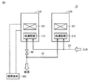
図1を参照して、本実施の形態に従う給湯システム10は、暖房機能および給湯機能の両方を有する温水暖房熱源機である暖房給湯器100と、給湯専用の給湯器200と、入水管20と、出湯管40とを有する。
Referring to FIG. 1, the hot
暖房給湯器100は、加熱機構101および給湯回路110を有する。給湯回路110は、加熱機構101によって加熱された熱媒体を暖房端末300との間で循環通流させることによる暖房機能を有する。さらに、給湯回路110は、暖房機能と共通の熱媒体を用いて、入水管20から導入された低温水の少なくとも一部を加熱することにより、出湯管40に対して出力する給湯機能を有する。
The
給湯器200は、加熱機構201および給湯回路210を有する。給湯器200は、加熱機構201が発生した熱量を用いて、入水管20から導入された低温水の少なくとも一部を加熱して、出湯管40に出湯することができる。
The
このように、給湯システム10は、出湯管40に対して並列に接続された、給湯回路110(暖房給湯器100)および給湯器200(給湯回路210)の両方からの出湯による給湯運転を実行することができる。これにより、給湯システム10の給湯能力が増大する。
In this way, the hot
一方で、暖房給湯器100では、加熱機構101によって加熱された熱媒体の一部を用いて給湯回路110で加熱された湯水を、出湯管40へ出力することができる。このため、暖房給湯器100では、給湯および暖房の同時運転時には、加熱機構101によって加熱された熱媒体の一部が給湯運転のために利用されることによって、暖房端末300へ供給される熱媒体が減少することにより、暖房機能が低下することが懸念される。
On the other hand, in the
本実施の形態に従う給湯システム10では、給湯回路110に対応して遮断機構90が配置される。遮断機構90は、代表的には、電気信号に応じて開放または閉止される電磁開閉弁によって構成することができる。遮断機構90が遮断(閉止)されると、給湯回路110では、流路が遮断されることにより、低温水の導入および出湯が停止される。したがって、給湯システム10では、遮断機構90の閉止による給湯回路210単独での給湯運転、および、遮断機構90の開放による、給湯回路110および給湯回路210の両方による給湯運転が選択的に実行できる。
In the hot
なお、図1の構成において、暖房給湯器100は「第1の熱源機」の一実施例に対応し、給湯器200は「第2の熱源機」の一実施例に対応する。さらに、給湯回路110は「第1の給湯回路」の一実施例に対応し、給湯回路210は「第2の給湯回路」の一実施例に対応する。さらに、加熱機構101は「第1の加熱機構」に対応し、加熱機構201は「第2の加熱機構」に対応する。
In the configuration of FIG. 1, the
図2は、暖房給湯器100の運転状態の遷移図である。
図2を参照して、後述のリモートコントローラ(以下、単に「リモコン」とも称する)によって、暖房給湯器100を含む給湯システム10の運転スイッチがオンされると、暖房給湯器100は、運転オフ状態から運転オン状態に遷移する。運転オン状態では、暖房給湯器100が電源投入された状態となり、各構成機器が動作可能な状態となる。一方で、加熱機構101は停止されており、加熱機構101の作動(燃焼)による熱媒体の加熱は待機される。
FIG. 2 is a transition diagram of the operating state of the
With reference to FIG. 2, when the operation switch of the hot
運転オン状態において、暖房端末300からの暖房要求がオンされると、暖房給湯器100は、暖房端末300へ熱媒体を供給する暖房運転を実行する。暖房運転では、加熱機構101が作動することにより、加熱された熱媒体が暖房端末300を通流する熱媒体の暖房循環経路(後述)が形成される。
When the heating request from the
暖房運転時に暖房端末300からの暖房要求がオフされると、暖房給湯器100は、運転オン状態に復帰する。これにより、加熱機構101は停止する。
When the heating request from the
一方で、運転オン状態において、出湯管40に接続された給湯栓(図示せず)の開栓により、水道水の水圧によって給湯回路110に流量が生じると、具体的には、給湯回路110での流量が最小作動流量(MOQ)を超えると、暖房給湯器100は、加熱機構101で加熱された熱媒体を用いて低温水を加熱する給湯運転を実行する。
On the other hand, when the hot water supply tap (not shown) connected to the hot
給湯運転時に、上述の給湯栓の閉栓によって給湯回路110での流量が最小作動流量よりも低下すると、給湯運転のオフ条件の成立により、暖房給湯器100は、運転オン状態に復帰する。これにより、加熱機構101は停止される。
When the flow rate in the hot
暖房運転時に給湯回路110での流量が最小作動流量を超えると、あるいは、給湯運転時に暖房端末300からの暖房要求がオンされると、暖房給湯器100は、給湯および暖房の同時運転を実行する。
When the flow rate in the hot
同時運転中に、暖房端末300からの暖房要求がオフされると、暖房給湯器100は、給湯運転に遷移する。また、同時運転中に、給湯回路110での流量が最小作動流量よりも低下すると、暖房給湯器100は、暖房運転に遷移する。また、同時運転中に、暖房要求のオフと、給湯回路110での流量低下とが同時に成立すると、暖房給湯器100は運転オン状態に復帰して、加熱機構101は停止される。反対に、運転オン状態で、暖房要求のオンおよび給湯回路110での流量上昇が同時に成立すると、暖房給湯器100は直接、同時運転に遷移することができる。
When the heating request from the
運転オン状態において、運転スイッチが操作された場合には、暖房給湯器100は、運転オフ状態に戻される。また、暖房運転中、給湯運転中、および、同時運転中の各々において、運転スイッチ(図示せず)が操作されると、暖房給湯器100は、加熱機構101を停止するとともに、直接、運転オフ状態に遷移することができる。
When the operation switch is operated in the operation on state, the
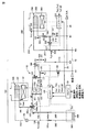
図3は、図1に示された暖房給湯器100および給湯器200の構成を詳細に説明するブロック図である。
FIG. 3 is a block diagram illustrating the configurations of the
図3を参照して、給湯器200は、「第2の加熱機構」の一例である燃焼バーナ201と、図1に示された給湯回路210と、コントローラ230とを備える。給湯回路210は、熱交換器204、入水管212、出湯管215、バイパス管216、バイパス流量弁220、および、流量調整弁280を含む。コントローラ230は、代表的には、マイクロコンピュータを含んで構成される。燃焼バーナ201および熱交換器204は、燃焼缶体(以下、単に「缶体」とも称する)202に格納される。
With reference to FIG. 3, the
入水管212は、ノードN1において給湯システム10の入水管20と接続される。入水管212は、熱交換器204の入力側とさらに接続される。熱交換器204を通過する低温水は、燃焼バーナ201の発生熱量によって加熱される。例えば、燃焼バーナ201は、作動時には、供給された燃料ガスを図示しないバーナで燃焼することによって熱量を発生する。燃焼バーナ201の発生熱量は、バーナの点火本数や燃料ガスの流量により、コントローラ230によって制御することができる。熱交換器204で加熱された高温水は、出湯管215へ出力される。出湯管215は、ノードN3において給湯システム10の出湯管40と接続される。
The
なお、入水管212からは、バイパス流量弁220が配置されたバイパス管216が分岐される。したがって、入水管212に導入された低温水は、バイパス流量弁220の開度に従った分配比でバイパス管216へ分配される。バイパス流量弁220の開度は、コントローラ230によって制御される。
A
出湯管215には、バイパス管216との合流点217が設けられる。そして、熱交換器204で加熱された高温水と、バイパス管216を通過した低温水とが混合されて、出湯管40へ供給される。すなわち、バイパス流量弁220の開度によって、高温水および低温水の混合比率を制御することができる。
The hot
このように、出湯管40に接続された給水栓(図示せず)が開栓されると、給湯回路210には、入水管20での水道水圧等を供給圧として低温水が導入されることにより、当該低温水の少なくとも一部を加熱して出湯管215へ出力する給湯経路が形成される。
When the water tap (not shown) connected to the
入水管212には、低温水温度Tw2を検出する温度センサ221が配置され、熱交換器204の下流側には、加熱後の高温水温度Th2を検出する温度センサ222が配置される。さらに、出湯管215の合流点217よりも下流側には、給湯器200からの出湯温度To2を検出する温度センサ223が配置される。さらに、入水管212には、缶体202の流量Q2を検出するための流量センサ225が配置される。すなわち、流量センサ225は、給湯回路210の通流量を検出する。
A
コントローラ230は、暖房給湯器100のコントローラ130と、信号線35によって接続される。この結果、コントローラ130および230の間では、双方向の信号伝送によって、各種の情報およびデータを授受することができる。コントローラ130は、給湯システム10のリモコン50と通信可能に接続される。例えば、コントローラ130およびリモコン50の間、ならびに、コントローラ130および230の間は、2心通信線によって接続することができる。
The
リモコン50には、ユーザから給湯システム10の運転指令が入力される。例えば、運転指令は、給湯システム10の運転オン状態および運転オフ状態を切換えるための運転オンオフ指令、給湯運転における給湯設定温度指令が含まれる。リモコン50に入力された給湯設定温度は、コントローラ130からコントローラ230へ伝送される。
An operation command of the hot
コントローラ230は、給湯器200(給湯システム10)の運転オン状態において、給湯栓の開栓によって流量センサ225による流量検出値Q2が所定量(いわゆる、最小作動流量:MOQ)よりも多いと、燃焼バーナ201を作動させて出湯管215から出湯する。一方で、給湯器200(給湯システム10)の運転オフ状態では、流量センサ225の検出流量によらず、燃焼バーナ201は停止状態(非燃焼)に維持される。
The
コントローラ230は、燃焼バーナ201の作動時、すなわち、出湯時には、高温水温度Th2が給湯設定温度よりも高い高温水設定温度となるように、燃焼バーナ201の発生熱量を制御する。さらに、コントローラ230は、給湯器200からの出湯温度To2(温度センサ223)が給湯設定温度と一致するように、バイパス流量弁220の開度を制御する。なお、バイパス流量弁220は、全閉状態(開度=0)として、低温水の全量を熱交換器204へ供給することも可能である。あるいは、バイパス管216およびバイパス流量弁220の配置を省略して、低温水の全量が熱交換器204を通流する構成とすることも可能である。
The
流量調整弁280は、熱交換器204の通流路に接続される。流量調整弁280の開度に応じて、熱交換器204において加熱される流量を制限することができる。流量調整弁280についても、全閉状態(開度=0)として流路の遮断が可能なタイプの弁を用いることができる。
The flow
次に、暖房給湯器100の構成を説明する。
暖房給湯器100は、給湯回路110による給湯機能と、暖房端末300に対して熱媒体(高温水)を供給する暖房機能とを有する。また、暖房給湯器100では、暖房機能に用いる熱媒体との熱交換によって低温水を加熱することで、給湯機能が実現される。
Next, the configuration of the
The
暖房給湯器100は、暖房端末300と接続される、熱媒体の入力端141aおよび出力端141bと、配管143〜147と、分配弁160と、循環ポンプ170とを備える。「第1の加熱機構」の一例である燃焼バーナ101および熱交換器104は、缶体102に格納される。燃焼バーナ101は、燃焼バーナ201と同様に、作動時には、供給された燃料ガスを燃焼することによって熱量を発生する。熱交換器104は、通流する熱媒体を燃焼バーナ101の発生熱量によって加熱する。
The
暖房端末300は、放熱体305を含む。暖房端末300は、外部配管302および305によって、入力端141aおよび出力端141bの間に接続される。暖房端末300は、図示しない制御部をさらに備える。当該制御部は、暖房給湯器100のコントローラ130に対して、2値信号である暖房運転信号Sstを出力する。例えば、ユーザ操作に応じて暖房端末300の運転を開始する際に、暖房運転信号Sstは「0」から「1」に変化する。一方で、運転中の暖房端末300がユーザ操作に応じて停止する際には、暖房運転信号Sstは「1」から「0」に変化する。
The
配管143は、入力端141aおよび熱交換器104の入力側を接続する。配管144は、熱交換器104の出力側および分配弁160の第1ノード160aを接続する。配管145は、分配弁160の第2ノード160bおよび出力端141bを接続する。燃焼バーナ101による発生熱量は、燃焼バーナ101の点火本数や燃料ガスの流量により、コントローラ130によって制御することができる。
The
配管146は、分配弁160の第3ノード160cおよび給湯用熱交換器150の一次側経路151の入力側を接続する。配管147は、給湯用熱交換器150の一次側経路151の出力側を配管143と接続する。分配弁160の開度によって、第1ノード160aおよび第2ノード160bの経路の流量と、第1ノード160aおよび第3ノード160cの経路の流量との比率が制御される。循環ポンプ170は、配管143において、配管147との合流点よりも下流側(熱交換器104側)に配設される。
The
配管143には、熱媒体の入力温度Ti1を検出するための温度センサ126が配置される。熱交換器104の出力側に配置された温度センサ127は、熱交換器104による加熱後の熱媒体の出力温度Thm1を検出する。
A
図1に示された、暖房給湯器100の給湯回路110は、入水管112と、出湯管115と、バイパス管116と、バイパス流量弁120と、給湯用熱交換器150と、流量調整弁180とを含む。給湯用熱交換器150は、一次側経路151および二次側経路152の間での伝熱機構を有する。入水管112は、ノードN2において、給湯システム10の入水管20と接続される。暖房給湯器100の出湯管115は、給湯システム10の出湯管40とノードN4において接続される。入水管112および出湯管115を含む給湯回路110による通流路には、電磁開閉弁190が接続される。
The hot
暖房給湯器100は、さらに、コントローラ130を備える。コントローラ130は、代表的には、マイクロコンピュータを含んで構成される。上述のように、コントローラ130は、給湯システム10のリモコン50と通信可能に接続される。リモコン50に入力される運転指令は、暖房機能に関する指令、例えば、段階的に設定される暖房運転の暖房能力を含む。暖房能力が高く設定される程、暖房給湯器100からの熱媒体の出力温度目標値を高く設定することができる。
The
給湯回路110において、入水管112は、給湯用熱交換器150の二次側経路152の入力側と接続される。出湯管115は、給湯用熱交換器150の二次側経路152の出力側と接続される。バイパス管116およびバイパス流量弁120は、入水管112および出湯管115の間に接続される。
In the hot
流量調整弁180は、入水管112および出湯管115による給湯回路110の通流路に直列に接続される。流量調整弁180の開度に応じて、給湯回路110の流量を制限することができる。
The flow
なお、本実施の形態では、給湯回路110の流量調整弁180に、全閉による流路遮断機能を有さないタイプの弁が適用される例を説明する。したがって、図1に示された、給湯回路110の遮断機構90として、コントローラ130からの制御指令に応じて開閉される電磁開閉弁190が配置されている。電磁開閉弁190は、非通電時には閉状態である一方で、コントローラ130からの制御指令に応じて励磁されることで開放される、ノーマリオフタイプの電磁弁によって構成される。なお、流量調整弁180が全閉による流路遮断機能を有する場合には、電磁開閉弁190の配置を省略して、流量調整弁180によって遮断機構90(図1)を構成することも可能である。
In this embodiment, an example in which a valve of a type that does not have a flow path cutoff function by fully closing is applied to the flow
給湯回路110には、入水管112において、給湯回路110に導入された低温水の温度(以下、低温水温度Tw1)を検出する温度センサ121と、流量センサ125とが配置される。すなわち、流量センサ125は、給湯回路110の通流量Q1を検出する。さらに、出湯管115において、給湯用熱交換器150(二次側経路152)の出力(下流)側には、加熱後の高温水温度Th1を検出する温度センサ122が配置される。さらに、出湯管115における、バイパス管116との合流点117よりも下流側には、暖房給湯器100からの出湯温度To1を検出する温度センサ123が配置される。
In the hot
上述のように、コントローラ130および230の間では、信号線35を経由した双方向の信号伝送によって、各種の情報およびデータを授受することができる。ユーザからの運転指令に従って給湯システム10を動作させるためには、暖房給湯器100および給湯器200の各々の単体の動作制御に加えて、暖房給湯器100および給湯器200を協調的に動作させることが必要となる。この協調的な制御については、上述した信号線35を用いて伝送される情報およびデータを用いて、コントローラ130および230の一方または両方によって実行することができる。したがって、以下では、給湯システム10の制御を説明する場合において、コントローラ130および230を包括的に表記する場合には、コントローラ30とも表記する。すなわち、以下の説明において、コントローラ30による制御動作は、コントローラ130および230の一方または両方によって実行可能であることを意味している。
As described above, various information and data can be exchanged between the
コントローラ130は、リモコン50に入力された運転指令に従って給湯システム10が動作するように、図2に示した、暖房運転、給湯運転、および、同時運転の切換え、ならびに、各運転での設定指令値(具体的には、給湯設定温度および暖房能力)に従う動作のために、暖房給湯器100の各構成機器を制御する。
The
コントローラ130には、温度センサ121〜123,126,127によって検出された、低温水温度Tw1、高温水温度Th1、出湯温度To1、ならびに、熱媒体の入力温度Ti1および出力温度Thm1が入力される。さらに、コントローラ130には、流量センサ125による流量検出値Q1および暖房端末300からの暖房運転信号Sstが入力される。
The low temperature water temperature Tw1, the high temperature water temperature Th1, the hot water temperature To1, and the input temperature Ti1 and the output temperature Thm1 of the heat medium, which are detected by the
コントローラ130は、バイパス流量弁120および流量調整弁180の開度、電磁開閉弁190の開閉、燃焼バーナ101の作動/停止および発生熱量、循環ポンプ170の作動/停止、ならびに、分配弁160の開度を制御する。
The
暖房運転では、循環ポンプ170を作動するとともに、分配弁160が第1ノード160aおよび第2ノード160bの間に熱媒体の経路を形成することによって、暖房端末300との間で熱媒体を循環するための暖房循環経路が形成される。暖房給湯器100の内部では、暖房循環経路は、入力端141aおよび出力端141bの間において、配管143、熱交換器104、配管144、分配弁160の第1ノード160aおよび第2ノード160b、ならびに、配管145を含むように形成される。
In the heating operation, the
一方で、分配弁160が第1ノード160aおよび第3ノード160cの間に熱媒体の経路を形成することにより、配管146および147によって、暖房端末300をバイパスした熱媒体が、給湯用熱交換器150の一次側経路151を通流するバイパス経路を形成することができる。これにより、循環ポンプ170を作動させることによって、バイパス経路に熱交換器104で加熱された熱媒体を通流することができる。また、分配弁160の開度に応じて、暖房循環経路の流量に対するバイパス経路への分流比率を制御することができる。
On the other hand, the heat medium bypassing the
コントローラ130は、暖房給湯器100の運転オン状態において、暖房運転信号Sstが「1」に設定されると、循環ポンプ170および燃焼バーナ101を作動させて、熱媒体を加熱するとともに、上述の暖房循環経路を形成する。燃焼バーナ101の発生熱量は、熱媒体の出力温度Thm1が、設定された暖房能力に対応する出力温度目標と一致するように制御される。
When the heating operation signal Sst is set to "1" in the operation on state of the
暖房運転中に、流量センサ125の流量検出値Q1が所定の最低流量よりも少ない場合には、暖房運転のみが実行されるので、分配弁160は、熱媒体の全量が暖房循環経路を通流するように制御される。
During the heating operation, if the flow rate detection value Q1 of the
一方で、暖房および給湯の同時運転では、循環ポンプ170および燃焼バーナ101が作動した状態で、分配弁160は、加熱後の熱媒体の一部がバイパス経路を通流するように制御される。これにより、給湯用熱交換器150では、入水管112から二次側経路152に導入された低温水が、一次側経路151を通流する熱媒体によって加熱される。この結果、出湯管115からは、給湯用熱交換器150による加熱後の高温水と、バイパス管116を通過した低温水とを混合して給湯することができる。バイパス流量弁120の開度調整によって、暖房給湯器100からの出湯温度To1は給湯温度目標値に制御される。
On the other hand, in the simultaneous operation of heating and hot water supply, the
給湯運転時にも、循環ポンプ170および燃焼バーナ101が作動される。さらに、分配弁160は、熱交換器104で加熱された熱媒体の全量がバイパス経路を通流するように制御される。給湯運転における熱媒体の出力温度目標値は、暖房運転および同時運転とは異なる値に設定されることが好ましい。給湯運転においても、暖房給湯器100からの出湯温度To1は、バイパス流量弁120の開度調整によって給湯温度目標値に制御される。
The
図3に示されるように、暖房給湯器100の出湯管115および給湯器200の出湯管215は、給湯システム10の出湯管40に対して並列に接続される。図1でも説明したように、遮断機構90(図1)を構成する電磁開閉弁190の開閉に応じて、給湯システム10による給湯運転は、給湯器200からの出湯のみによる単独モードと、暖房給湯器100および給湯器200の両方からの出湯による並列モードとを切換えることができる。
As shown in FIG. 3, the hot
具体的には、電磁開閉弁190の閉止時(単独モード)には、給湯回路110での流路が遮断されて流量検出値Q1が上昇しないため、暖房給湯器100では給湯運転は実行されない。すなわち、暖房給湯器100は、暖房要求オン時には暖房運転を実行する一方で、暖房要求オフ時には、加熱機構101(燃焼バーナ101)を停止する。この結果、給湯器200からの出湯のみによって、給湯システム10の給湯運転が実行される。
Specifically, when the electromagnetic on-off
これに対して、電磁開閉弁190の開放時(並列モード)には、給湯回路110での流路における流量検出値Q1が最小作動流量よりも大きくなることに応じて、暖房給湯器100でも給湯運転が開始される。すなわち、暖房給湯器100は、暖房要求オン時には暖房および給湯の同時運転を実行する一方で、暖房要求オフ時には、加熱機構101(燃焼バーナ101)を作動して給湯運転を実行する。
On the other hand, when the electromagnetic on-off
給湯システム10では、暖房給湯器100での加熱能力の一部を給湯運転に用いることによって給湯能力(給湯量)を増大することができる。一方で、暖房給湯器100による暖房機能の低下を抑制することが必要となる。特に、一般的な給湯システムに倣って、低流量時から高流量時を通じて出湯するメイン給湯器と、高流量時にのみ出湯するサブ給湯器との分担をローテーションすると、暖房給湯器がメイン給湯器に割り当てられたときに、暖房端末へ供給できる熱媒体が減少することによって、暖房能力が低下することが懸念される。
In the hot
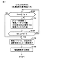
図4は、給湯システム10における実施の形態1に従う給湯運転の制御処理を説明するフローチャートである。図4に示すフローチャートは、給湯システム10の運転開始時に起動される。上述のように、給湯システム10における給湯運転の制御は、コントローラ130および230を包括的に表記するコントローラ30によって実行することができる。
FIG. 4 is a flowchart illustrating a control process of the hot water supply operation according to the first embodiment in the hot
図4を参照して、コントローラ30は、ステップS110により、初期化処理として、電磁開閉弁190を閉止する。すなわち、コントローラ230から電磁開閉弁190への制御指令(励磁指令)が非生成とされる。
With reference to FIG. 4, the controller 30 closes the electromagnetic on-off
コントローラ30は、ステップS120により、流量センサ225によって検出される給湯器200(給湯回路210)の流量検出値Q2が、所定の最小作動流量(MOQ)よりも大きいかどうかを判定する。流量検出値Q2がMOQに達していないとき(S120のNO判定時)には、給湯器200において燃焼バーナ201が停止されるとともに、暖房給湯器100では給湯運転が実行されないため、給湯回路110および210の両方で出湯がオフされる。すなわち、給湯システム10からは給湯を実行されない(S200)。
In step S120, the controller 30 determines whether or not the flow rate detection value Q2 of the water heater 200 (hot water supply circuit 210) detected by the
コントローラ30は、流量検出値Q2がMOQを超えると(S120のYES判定時)、ステップS130により、給湯器200(給湯回路210)からの出湯をオンする。具体的には、給湯器200において燃焼バーナ201が作動することによって、給湯回路210から出湯管40に給湯設定温度に従った湯が出力される。このように、給湯運転は、単独モードで開始される。
When the flow rate detection value Q2 exceeds MOQ (when YES is determined in S120), the controller 30 turns on the hot water from the water heater 200 (hot water supply circuit 210) by step S130. Specifically, when the
コントローラ30は、単独モードによる給湯運転時には、ステップS140およびS150により、給湯回路210による給湯負荷が基準値よりも大きいかどうかを判定する。例えば、ステップS140では、流量検出値Q2が所定流量qtよりも大きいかどうかを判定するとともに、ステップS150により、給湯器200による給湯熱量Qld(2)が所定の基準値Qt1よりも大きいか否かを判定する。
During the hot water supply operation in the independent mode, the controller 30 determines in steps S140 and S150 whether or not the hot water supply load by the hot
給湯熱量Qld(2)は、給湯回路210における、給湯設定温度Trおよび低温水温度Tw2の温度差(Tr−Tw2)である昇温量と、流量検出値Q2との積によって算出される。一般的に、給湯熱量Qld(2)は、号数を単位として示される。なお、号数=1(1号)は、Q2=1[L/min]を15℃昇温するのに必要な熱量に相当する。例えば、基準値Qt1は、給湯器200による最大加熱能力(最大号数)の所定の割合(例えば、60(%))に設定することができる。
The hot water supply heat amount Qld (2) is calculated by the product of the temperature rise amount (Tr-Tw2), which is the temperature difference (Tr-Tw2) between the hot water supply set temperature Tr and the low temperature water temperature Tw2, and the flow rate detection value Q2 in the hot
給湯器200における給湯負荷が基準値以下の場合、すなわち、ステップS140またはS150がNO判定時の場合には、処理はステップS120に戻される。したがって、給湯回路210の流量検出値Q2がMOQよりも大きい間は、給湯回路210単体による単独モードでの給湯が継続される。一方で、単独モードによる給湯運転中に、給湯回路210の流量検出値Q2がMOQよりも低下すると、ステップS120がNO判定されることにより、給湯システム10からの給湯が停止される(S200)。そして、ステップS110からの処理が再び起動される。
When the hot water supply load in the
単独モードによる給湯運転中に、給湯器200における給湯負荷が増大してステップS140およびS150がYES判定とされると、コントローラ30は、ステップS160に処理を進めて、電磁開閉弁190を開放する。すなわち、コントローラ130から電磁開閉弁190を開放するための制御指令が出力される。
If the hot water supply load in the
電磁開閉弁190が開放されると、給湯回路110の流路が形成されることによって流量検出値Q1(流量センサ125)がMOQよりも大きくなる。これに応じて、暖房給湯器100では、加熱機構101の作動を伴う運転オン状態から給湯運転への遷移、または、暖房運転から同時運転への遷移が生じる。この結果、入水管112に導入された低温水の少なくとも一部が、給湯用熱交換器150の二次側経路152を通流することにより、加熱機構101によって加熱された熱媒体との熱交換によって加熱される。
When the electromagnetic on-off
暖房給湯器100からも出湯が開始されることにより、コントローラ30は、ステップS170により、暖房給湯器100および給湯器200の両方から出湯する並列モードによる給湯運転を実行する。
When hot water is also started from the
このとき、出湯管40からの供給量は、給湯先となる給湯栓(開栓状態)の個数およびその開度と、水道水の供給圧との組合せで決まる。また、給湯システム10からの給湯量に対する、給湯回路210(給湯器200)および給湯回路110(暖房給湯器100)の出湯量の比は、給湯回路110および210のそれぞれでの圧力損失等による流路抵抗の逆比に従って決まる。
At this time, the amount of supply from the hot
並列モードによる給湯運転中は、コントローラ30は、ステップS180により、給湯器200の給湯負荷を監視する。そして、給湯負荷が予め定められた基準値よりも低下すると(S180のYES判定時)、コントローラ30は、ステップS190により、電磁開閉弁190を閉止する。
During the hot water supply operation in the parallel mode, the controller 30 monitors the hot water supply load of the
これにより、給湯回路110の流路が遮断されるので、給湯回路110からの出湯が停止される。給湯回路110の流量検出値Q1がMOQよりも低くなる。これにより、暖房給湯器100では、同時運転から暖房運転への遷移(暖房要求オン時)または、加熱機構101の停止を伴う給湯運転から運転オン状態への遷移(暖房要求オフ時)が生じる。この結果、給湯回路110(暖房給湯器100)からの出湯は停止される。コントローラ30は、ステップS190の後、処理をステップS120に戻す。これにより、上述したステップS120〜S150による、単独モードでの給湯運転が実行される。
As a result, the flow path of the hot
一方で、並列モードによる給湯運転において、給湯器200の給湯負荷が基準値以上である間(S180のNO判定時)には、ステップS170による並列モードによる給湯運転が継続される。
On the other hand, in the hot water supply operation in the parallel mode, while the hot water supply load of the
なお、給湯器200の給湯負荷に係る判定に関して、ステップS180での基準値を、ステップS140,S150での基準値よりも低く設定することで、単独モードおよび並列モードの切換えが過度に生じることを抑制できる。
Regarding the determination of the hot water supply load of the
図5は、実施の形態1に従う給湯運転の動作例を説明する概念的な波形図である。
図5を参照して、電磁開閉弁190が閉止された状態で給湯システム10の運転が開始され、時刻taにおいて、給湯回路210の流量検出値Q2がMOQを超えるのに応じて、給湯回路210(給湯器200)からの出湯が開始される。さらに流量検出値Q2が増加して、時刻tbにおいて、給湯器200による給湯負荷が基準値を超える。これにより、時刻tbでは、ステップS140,S150がYES判定とされて、電磁開閉弁190が開放されることにより(S160)、給湯回路110(暖房給湯器100)からの出湯も開始される。
FIG. 5 is a conceptual waveform diagram illustrating an operation example of the hot water supply operation according to the first embodiment.
With reference to FIG. 5, the operation of the hot
すなわち、時刻ta〜tbの間には、給湯器200のみで出湯量が賄えるため、電磁開閉弁190が閉止されて、単独モードでの給湯運転が実行される一方で、時刻tbからは、給湯回路110および210の両方からの出湯による並列モードの給湯運転が開始される。
That is, since the amount of hot water discharged can be covered only by the
時刻tbからの並列モードでの給湯運転中に、時刻tcにおいて、給湯量の減少により、給湯器200の給湯負荷が基準値よりも低下すると、図4のステップS180がYES判定されることに応じて、電磁開閉弁190が閉止される(S190)。これにより、給湯回路110(暖房給湯器100)からの出湯が停止されて、再び、給湯回路210(給湯器200)のみによる単独モードでの給湯運転が開始される。
During the hot water supply operation in the parallel mode from the time tb, when the hot water supply load of the
時刻tcから開始された単独モードでの給湯運転において、給湯流量がさらに低下して、時刻tdでは、給湯回路210の流量検出値Q2がMOQ♯よりも低下する。なお、MOQ♯は、給湯開始を判定するためのMOQ(時刻tb)よりも低く設定されることが好ましい。これに応じて、時刻tdでは、給湯器200における燃焼バーナ201が停止されて、給湯回路210からの出湯がオフされる。これにより、給湯システム10の給湯運転が停止される。
In the hot water supply operation in the independent mode started from the time ct, the hot water supply flow rate further decreases, and at the time td, the flow rate detection value Q2 of the hot
このように実施の形態1に従う給湯システムでは、給湯器200単体からの出湯によって給湯運転を開始するとともに、暖房用の加熱能力の一部を用いて給湯する暖房給湯器100については、給湯器200の給湯負荷が大きくなったときに限定して出湯する態様で、給湯運転が実行される。すなわち、低流量時から高流量時を通じて出湯するメイン給湯器には給湯器200が固定的に割り当てられる。この結果、給湯器200および暖房給湯器100の並列出湯によって給湯能力(最大給湯量)を増大できるとともに、暖房給湯器100からの出湯を最小限とすることができるので、暖房給湯器100の暖房機能の低下を抑制することができる。
As described above, in the hot water supply system according to the first embodiment, the hot water supply operation is started by the hot water discharged from the
また、図3の構成例のように、液体同士の熱交換によって暖房給湯器100の給湯機能が実現される場合には、給湯器200をメイン給湯器に固定することによって、給湯システムの給湯運転開始時における出湯温度の立ち上がりが早くなるので、温度精度を向上することができる。
Further, when the hot water supply function of the
[実施の形態2]
実施の形態1で説明した給湯システムでは、給湯器200をメイン給湯器に固定して、暖房給湯器100による出湯の機会を抑制することで、暖房能力の低下を抑制している。この結果、暖房給湯器100が長期間出湯しないことにより、暖房給湯器100の給湯回路110の内部に、長期間の滞留水が生じることが懸念される。
[Embodiment 2]
In the hot water supply system described in the first embodiment, the
図3の構成例では、電磁開閉弁190が閉止されることにより、入水管20上のノードN2から、入水管112、および、給湯用熱交換器150の二次側経路152を経由して、出湯管115の電磁開閉弁190までの経路(以下、「滞留経路」とも称する)に、長期間の滞留水が発生するおそれがある。実施の形態2では、このような滞留水の発生を検知して、長期間に亘って給湯回路110内に水が滞留しないように、自動的に排出するための制御について説明する。
In the configuration example of FIG. 3, when the electromagnetic on-off
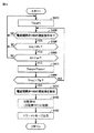
図6は、実施の形態2に従う給湯システムでの滞留水の検出処理手順を説明するフローチャートである。図6の制御処理についても、コントローラ130および/または230、すなわち、コントローラ30によって実行することが可能である。
FIG. 6 is a flowchart illustrating a procedure for detecting stagnant water in the hot water supply system according to the second embodiment. The control process of FIG. 6 can also be executed by the
図6を参照して、コントローラ30は、ステップS210により、滞留水の検出のための各パラメータの初期化処理を実行する。具体的には、流量センサ125の通流量、すなわち流量検出値Q1を積算するための流量積算値Qsumが0にクリアされ、滞留判定フラグFtrが「滞留水検出有り」を示す値(Ftr=1)に設定される。さらに、滞留水を除去するための強制通流制御の要求フラグFctlが、制御不要を示す値(Fctl=0)に初期化される。
With reference to FIG. 6, the controller 30 executes initialization processing of each parameter for detecting stagnant water in step S210. Specifically, the flow rate of the
コントローラ30は、ステップS220により、給湯回路110に通流が生じているか否かを、流量センサ125の流量検出値Q1によって判定する。Q1>0のとき(S220のYES判定時)には、コントローラ30は、ステップS230により、流量積算値Qsumの現在値に対して現在の流量検出値Q1を加算する。さらに、ステップS240により、加算後の流量積算値Qsumが基準値Rと比較される。基準値Rは、給湯回路110による保有水量、より詳細には、上述した図3での滞留経路の配管での保有水量に対応させて予め定めることができる。
The controller 30 determines in step S220 whether or not a flow has occurred in the hot
コントローラ30は、Qsum>Rのとき(S240のYES判定時)には、ステップS250に処理を進めて、滞留判定フラグFtrを、「滞留水検出無し」を示す値(Ftr=0)へ変化させる。ステップS250では、要求フラグFctl=0に維持される。 When Qsum> R (when YES is determined in S240), the controller 30 proceeds to step S250 to change the retention determination flag Ftr to a value (Ftr = 0) indicating "no retention water detection". .. In step S250, the request flag Fctl = 0 is maintained.
コントローラ30は、流量積算値Qsumが基準値Rに達していないとき(S240のNO判定時)には、ステップS250による処理をスキップする。すなわち、流量積算値Qsumが更新される一方で、滞留判定フラグFtr=1(滞留水検出有り)に維持される。 When the flow rate integrated value Qsum does not reach the reference value R (NO determination in S240), the controller 30 skips the process in step S250. That is, while the flow rate integrated value Qsum is updated, the retention determination flag Ftr = 1 (with retention water detection) is maintained.
コントローラ30は、Q1=0、すなわち、給湯回路110に通流が生じていないとき(S220のNO判定時)には、ステップS260により、流量積算値Qsumをクリアする(Qsum=0)。これにより、流量積算値Qsumは、給湯回路110での連続した通流状態においてのみ積算される。長期間に亘る間欠的な通流によって流量積算値Qsumが基準値Rを超えても、実際には長期間の滞留水が存在している可能性があるので、かかるケースにおいて、滞留判定フラグFtrがクリア(Ftr=0)されること(S250)を排除するためである。
When Q1 = 0, that is, when no flow is generated in the hot water supply circuit 110 (NO determination in S220), the controller 30 clears the flow rate integrated value Qsum by step S260 (Qsum = 0). As a result, the flow rate integrated value Qsum is integrated only in the continuous flow state in the hot
コントローラ30は、ステップS220〜S260による処理を一定の制御周期毎に実行するとともに、ステップS270により、前回の滞留判定タイミングから所定時間が経過したかどうかを判定する。所定時間は、例えば、日数オーダーとすることができる。 The controller 30 executes the processing according to steps S220 to S260 at regular control cycles, and determines whether or not a predetermined time has elapsed from the previous residence determination timing in step S270. The predetermined time can be, for example, the number of days order.
コントローラ30は、前回のS280での判定から所定時間が経過すると(S270のYES判定時)、ステップS280により滞留判定を実行する。すなわち、ステップS270は、所定時間が経過する毎にYES判定とされる。一方で、所定時間が経過するまでの間(S270のNO判定時)では、S220〜S260による流量積算値Qsumの更新処理が繰返し実行される。 When a predetermined time has elapsed from the previous determination in S280 (when the determination is YES in S270), the controller 30 executes the retention determination in step S280. That is, step S270 is determined to be YES every time a predetermined time elapses. On the other hand, until the predetermined time elapses (at the time of NO determination in S270), the update process of the flow rate integrated value Qsum by S220 to S260 is repeatedly executed.
コントローラ30は、ステップS280により、滞留判定フラグFtrに基づいて滞留判定を実行する。Ftr=1のとき(S280のYES判定時)には、ステップS290により、要求フラグFctlが「1」に設定される。さらに、流量積算値Qsumがクリアされて(Qsum=0)、再びステップS220に処理が戻される。 The controller 30 executes the retention determination based on the retention determination flag Ftr in step S280. When Ftr = 1 (when YES is determined in S280), the request flag Fctl is set to "1" by step S290. Further, the flow rate integrated value Qsum is cleared (Qsum = 0), and the process is returned to step S220 again.
一方で、Ftr=0のとき(S280のNO判定時)には、ステップS300により、ステップS210と同様の初期化処理が行われた後、再びステップS220に処理が戻される。 On the other hand, when Ftr = 0 (NO determination in S280), the initialization process similar to that in step S210 is performed by step S300, and then the process is returned to step S220 again.
このように、図6に従う制御処理によれば、給湯回路110における保有水量(基準値R)を超える連続的な通流の有/無を監視する滞留判定が、所定時間毎(S270)に実行される。そして、当該通流が無いことにより滞留水の存在が検知されると、強制通流制御が要求される(Fctl=1)。
As described above, according to the control process according to FIG. 6, the retention determination for monitoring the presence / absence of continuous flow exceeding the retained water amount (reference value R) in the hot
図7は、実施の形態2に従う給湯システムにおける、滞留水の排出のための制御処理手順を説明するフローチャートである。図7の制御処理についても、コントローラ130および/または230、すなわち、コントローラ30によって繰り返し実行することが可能である。
FIG. 7 is a flowchart illustrating a control processing procedure for discharging stagnant water in the hot water supply system according to the second embodiment. The control process of FIG. 7 can also be repeatedly executed by the
図7を参照して、コントローラ30は、ステップS310により、要求フラグFctlが「1」であるかどうかを判定する。Fctl=0であるとき(S310のNO判定時)には、ステップS320以降の処理は実行されず、強制通流制御は起動されない。 With reference to FIG. 7, the controller 30 determines in step S310 whether the request flag Fctl is “1”. When Fctl = 0 (NO determination in S310), the processing after step S320 is not executed, and the forced flow control is not activated.
コントローラ30は、Fctl=1のとき(S310のYES判定時)には、ステップS320により、電磁開閉弁190が閉止中であるかどうかを判定する。電磁開閉弁190の閉止中(S320のYES判定時)には、コントローラ30は、ステップS330により、給湯器200からの出湯中、すなわち、給湯回路210の流量検出値Q2がMOQよりも大きい状態であるかどうかを判定する。
When Fctl = 1 (when YES is determined in S310), the controller 30 determines in step S320 whether or not the electromagnetic on-off
コントローラ30は、給湯器200からの出湯中には(S330のYES判定時)、ステップS340により強制通流制御を実行する。具体的には、強制通流制御では、電磁開閉弁190が開放されるとともに、流量調整弁180が所定開度に設定される。強制通流制御における流量調整弁180の開度は、比較的少ない流量によって滞留水を排出するように予め定められる。
The controller 30 executes forced flow control in step S340 while the hot water is being discharged from the water heater 200 (when YES is determined in S330). Specifically, in the forced flow control, the electromagnetic on-off
ステップS340による強制通流制御の実行中にも、図6に示したフローチャートによる滞留水の判定は実行されているため、強制通流制御によって給湯回路110での流量積算値Qsumが増加する。したがって、コントローラ30は、強制通流制御(S340)の実行中には、ステップS350により、図6によって制御される滞留判定フラグFtrが「0」に変化したかどうかを判定する。
Since the determination of the stagnant water according to the flowchart shown in FIG. 6 is executed even during the execution of the forced flow control in step S340, the forced flow control increases the flow rate integrated value Qsum in the hot
コントローラ30は、Ftr=1の間(S350のNO判定時)、すなわち、滞留判定がクリアされない間には、ステップS340による強制通流制御を継続する。コントローラ30は、滞留判定フラグがFtr=0にクリアされると(S350のYES判定時)、ステップS360により、強制通流制御をオフする。以降では、電磁開閉弁190の開放および閉止は、図4で説明した、給湯器200の給湯負荷に基づく制御処理によって決められる。
The controller 30 continues the forced flow control in step S340 while Ftr = 1 (at the time of NO determination in S350), that is, while the retention determination is not cleared. When the retention determination flag is cleared to Ftr = 0 (when YES determination in S350), the controller 30 turns off the forced flow control in step S360. Hereinafter, the opening and closing of the electromagnetic on-off
なお、電磁開閉弁190の閉止時であっても、給湯器200が出湯していない場合(S330のNO時)には、処理はステップS320へ戻されて、ステップS340による強制通流制御の実行は待機される。
If the
また、電磁開閉弁190の開放時(S320のNO判定時)には、給湯回路110から出湯されているので、強制通流制御(S340)は必要ない。したがって、ステップS330以降の処理は実行されない。
Further, when the electromagnetic on-off
図8は、実施の形態2に従う給湯システムの動作例を説明する概念的な波形図である。
図8を参照して、滞留判定(図6のステップS280)は、所定時間Tcの経過毎に実行される。図8の例では、時刻tx、tyに滞留判定が実行されている。また、図6のステップS260での処理により、流量積算値Qsumは、給湯回路210での連続的な通流が終わるたびに、Qsum=0にクリアされている。
FIG. 8 is a conceptual waveform diagram illustrating an operation example of the hot water supply system according to the second embodiment.
With reference to FIG. 8, the retention determination (step S280 in FIG. 6) is executed every time Tc elapses for a predetermined time. In the example of FIG. 8, the retention determination is executed at the times tx and ty. Further, by the process in step S260 of FIG. 6, the flow rate integrated value Qsum is cleared to Qsum = 0 each time the continuous flow in the hot
時刻txまでの期間では、時刻t1において、Qsum>Rとなっているため、当該タイミングで、滞留判定フラグFtrが初期値である「1」から「0」にクリアされる。この結果、時刻txでの滞留判定において、強制通流制御の要求フラグFctlは「0」に維持される。このため、時刻tx以降では、図7で説明した強制通流制御は実行されない。 In the period up to the time tx, since Qsum> R at the time t1, the residence determination flag Ftr is cleared from the initial value “1” to “0” at that timing. As a result, the request flag Fctl for forced flow control is maintained at "0" in the residence determination at the time tx. Therefore, after the time tx, the forced flow control described with reference to FIG. 7 is not executed.
一方、時刻tx〜tyの期間では、給湯流量が比較的小さく、流量積算値Qsumが基準値Rに達することなく、所定時間Tcが経過している。したがって、時刻tyでの滞留判定では、滞留判定フラグFtrが「1」に維持されているため、強制通流制御の要求フラグFctlが「1」に設定される。 On the other hand, in the period from time tx to ty, the hot water supply flow rate is relatively small, and the predetermined time Tc has elapsed without the flow rate integrated value Qsum reaching the reference value R. Therefore, in the residence determination at the time ty, since the retention determination flag Ftr is maintained at "1", the request flag Fctl for forced flow control is set to "1".
時刻tyにおいて要求フラグFctlが「1」に設定されると、給湯回路210での出湯に合わせて給湯回路110でも、流量調整弁180を所定開度として滞留水が出湯される。これにより、流量積算値Qsumが上昇する。
When the request flag Fctl is set to "1" at the time ty, the hot
時刻t2において、流量積算値Qsumが基準値Rに達すると、滞留判定フラグFtrおよび要求フラグFctlは「0」に設定されて、強制通流制御は終了される。時刻tyから所定時間Tcが経過すると次の滞留判定が実行されるが、当該滞留判定では、時刻txと同様に、滞留水の存在は検知されない。このように、所定時間Tcの経過毎に同様の滞留判定が実行されるとともに、滞留水の存在が検知されると、強制通流制御が実行される。 When the flow rate integrated value Qsum reaches the reference value R at time t2, the retention determination flag Ftr and the request flag Fctl are set to "0", and the forced flow control is terminated. When the predetermined time Tc elapses from the time ty, the next residence determination is executed, but the presence of the accumulated water is not detected in the residence determination as in the time tx. In this way, the same retention determination is executed every time the predetermined time Tc elapses, and when the presence of the retention water is detected, the forced flow control is executed.
このように実施の形態2に従う給湯システムによれば、実施の形態1で説明した、暖房機能の低下を抑制するための給湯制御において、給湯回路110の内部に長期間の滞留水が生じることを防止できる。
As described above, according to the hot water supply system according to the second embodiment, in the hot water supply control for suppressing the deterioration of the heating function described in the first embodiment, long-term retention water is generated inside the hot
[実施の形態3]
実施の形態3では、給湯器200および暖房給湯器100の両方から出湯する並列モードにおける給湯回路110(暖房給湯器100)の流量制限について説明する。並列モードによる給湯運転時における、上述のように、給湯回路110および210の流量の比率は、給湯経路の流路損失に起因する流量特性に従う。
[Embodiment 3]
In the third embodiment, the flow limit of the hot water supply circuit 110 (heating water heater 100) in the parallel mode in which hot water is discharged from both the
図9は、実施の形態3に従う給湯システムにおける給湯回路110および210の各々の流量特性を説明する概念的なグラフである。図9の横軸には流量(L/min)が示され、縦軸には、圧力(kPa)が示される。圧力は、上水道の供給水圧および開栓される給湯栓の個数および開度によって変化する。
FIG. 9 is a conceptual graph illustrating the flow rate characteristics of the hot
図9を参照して、流量特性CGQ1およびCGQ2は、給湯回路210の流量特性を示している。CGQ1は、流量調整弁280およびバイパス流量弁220の全開時における、圧力−流量の特性線である。一方で、CGQ2は、流量調整弁280が全開、かつ、バイパス流量弁220が全閉の場合における、圧力−流量の特性線である。CGQ1およびCGQ2の比較から、バイパス流量弁220の全開時(CGQ1)の方が経路全体での圧力損失が小さくなるため、同一圧力に対する流量が多いことが理解される。
With reference to FIG. 9, the flow rate characteristics CGQ1 and CGQ2 show the flow rate characteristics of the hot
一方で、流量特性CGHQ♯は、給湯回路110において、流量調整弁180を全開状態に設定したときの圧力−流量の特性線である。
On the other hand, the flow rate characteristic CGHQ # is a pressure-flow rate characteristic line when the flow
図10は、流量調整弁180の開度制御範囲を説明するための概念図である。図10には、一定圧力下での開度X(横軸)に対する流量(縦軸)の変化特性が示される。
FIG. 10 is a conceptual diagram for explaining an opening degree control range of the flow
図10を参照して、流量調整弁180は、全閉状態となる締切機能を有していないため、低流量域においては、開度の変化に対する流量の変化が小さい低感度の領域が存在する。このような低感度の領域を避けて、開度制御範囲の下限値Xminを設定することができる。一方で、流量調整弁180は、機構上はX=Xmaxにおいて全開状態となる。
With reference to FIG. 10, since the flow
すなわち、図9の流量特性CGHQ♯から理解されるように、流量調整弁180の全開状態時(X=Xmax)では、バイパス流量弁220の開度が大きい場合には、給湯回路110の流量が、給湯回路210の流量よりも多くなる。
That is, as can be understood from the flow rate characteristic CGHQ # in FIG. 9, when the flow
しかしながら、暖房機能の低下を抑制する観点からは、並列モードによる給湯運転時には、給湯回路110の流量が、給湯回路210の流量よりも少ないことが好ましい。すなわち、給湯回路110の流量特性CGHQ♯によれば、並列モードでの給湯により、暖房端末300に対する熱媒体の供給量の減少が懸念される。
However, from the viewpoint of suppressing the deterioration of the heating function, it is preferable that the flow rate of the hot
したがって、実施の形態3に従う給湯システムでは、流量調整弁180の開度制御範囲の上限値がXcmx(Xcmx<Xmax)に制限される。これにより、給湯回路110の流量特性が、図9上でCGHQ♯からCGHQへ変化する。流量特性CGHQによれば、流量調整弁180の開度が制御上限値Xcmxである場合でも、給湯回路110の流量は、給湯回路210の流量よりも少なくなる。
Therefore, in the hot water supply system according to the third embodiment, the upper limit of the opening control range of the flow
逆に言えば、図10における開度制御範囲の上限値Xcmxは、給湯回路110での圧力−流量特性に従って、CGHQのような流量特性を実現することができる開度の最大値に従って、予め定めることができる。
Conversely, the upper limit value Xcmx of the opening control range in FIG. 10 is predetermined according to the pressure-flow rate characteristic in the hot
給湯回路110の流量は、上述のように当該給湯経路の流路抵抗によって決まるため、流量調整弁180の開度制御範囲の上限値を制御する他にも、給湯回路110の流路抵抗を増加するハード機構によって、流量調整弁180が全開状態(X=Xmax)であっても、図9に示された流量特性CGHQを実現することが可能である。たとえば、給湯回路110の配管の一部または全部の配管径および/またはバルブ径を細くする設計により圧力損失を増加させることによって、流路抵抗を増加するハード機構を実現できる。
Since the flow rate of the hot
このように実施の形態3に従う給湯システムでは、流量調整弁180の開度制御範囲の上限値の制限、または、圧力損失を増加するためのハード機構の設計によって、給湯回路110および210の両方からの並列出湯時において、給湯回路110の流量(出湯量)を、給湯回路210の流量(出湯量)よりも少なくすることができる。この結果、並列モードによる給湯運転時において、暖房給湯器100による暖房機能の低下を抑えることができる。実施の形態3では、流量調整弁180の開度制御範囲の上限値の制限、および、給湯回路110の流路抵抗を増加するためのハード機構の少なくとも一方によって「流量制限手段」の機能を実現することができる。
Thus, in the hot water supply system according to the third embodiment, by limiting the upper limit of the opening control range of the flow
[実施の形態4]
図3の構成例では、暖房給湯器100では、加熱機構101からの熱媒体を用いた液体同士の熱交換によって給湯運転が実現される。このため、給湯回路110からの出湯開始時には、出湯温度To1が給湯設定温度に上昇するまで時間を要することによって、給湯システム10からの出湯温度が一時的に低下することが懸念される。
[Embodiment 4]
In the configuration example of FIG. 3, in the
したがって、実施の形態4に従う給湯システムでは給湯回路110からの出湯開始時にプレヒート制御を実行する。
Therefore, in the hot water supply system according to the fourth embodiment, the preheat control is executed at the start of hot water discharge from the hot
図11は、実施の形態4に従う給湯システムにおける給湯回路110のプレヒート制御を説明するフローチャートである。図11の制御処理は、図4の制御処理に追加して実行されるので、コントローラ30によって実行することが可能である。
FIG. 11 is a flowchart illustrating preheat control of the hot
図11を参照して、図4の制御処理での単独モードによる給湯時(給湯器200単独による出湯時)に、給湯器200の給湯負荷が増大してステップS140,S150がYES判定とされると、コントローラ30は、図11に示すステップS152〜S156の処理の実行後、ステップS160により電磁開閉弁190を開放する。
With reference to FIG. 11, during hot water supply in the independent mode in the control process of FIG. 4 (when hot water is discharged by the
図11を参照して、コントローラ30は、ステップS152により、温度センサ127によって検出された熱媒体の出力温度Thm1、すなわち、加熱機構101による加熱後の熱媒体温度をプレヒート判定温度Tαと比較する。コントローラ30は、Thm1≧Tαである場合には(S152のYES判定時)、プレヒート運転は不要と判断して、ステップS156に処理を進める。
With reference to FIG. 11, the controller 30 compares the output temperature Thm1 of the heat medium detected by the
一方で、コントローラ30は、熱媒体の出力温度Thm1がプレヒート判定温度Tαに達していないとき(S152のNO判定時)には、ステップS154によりプレヒート制御を実行する。プレヒート制御では、循環ポンプ170および燃焼バーナ101が作動した状態で、バイパス循環路、すなわち、給湯用熱交換器150の一次側経路151への熱媒体の流量比率が100(%)となるように分配弁160が制御される。なお、暖房運転から同時運転への移行時には、循環ポンプ170および燃焼バーナ101は既に作動しているので、分配弁160の制御によって、プレヒート制御が実現される。
On the other hand, when the output temperature Thm1 of the heat medium does not reach the preheat determination temperature Tα (NO determination in S152), the controller 30 executes the preheat control in step S154. In the preheat control, the flow rate ratio of the heat medium to the bypass circulation path, that is, the
コントローラ30は、ステップS155により、プレヒート制御(S154)が長時間継続しないようにタイマアウト判定を実行する。例えば、ステップS155は、プレヒート制御の開始から60秒が経過するとYES判定とされて、処理はステップS156へ進められる。一方で、タイムアウトの成立までは(S155のNO判定時)、熱媒体の出力温度Thm1がプレヒート判定温度Tαに達するまで、プレヒート制御(S154)が実行される。 The controller 30 executes the timer-out determination in step S155 so that the preheat control (S154) does not continue for a long time. For example, step S155 is determined to be YES when 60 seconds have elapsed from the start of preheat control, and the process proceeds to step S156. On the other hand, until the time-out is established (NO determination in S155), the preheat control (S154) is executed until the output temperature Thm1 of the heat medium reaches the preheat determination temperature Tα.
コントローラ30は、熱媒体の出力温度Thm1がプレヒート判定温度Tαに達すると(S152のYES判定時)、または、プレヒート制御が所定時間継続すると(S155のYES判定時)、ステップS156へ処理を進めて、燃焼バーナ101および分配弁160の制御を通常に戻す。これにより、プレヒート制御は終了される。
The controller 30 proceeds to step S156 when the output temperature Thm1 of the heat medium reaches the preheat determination temperature Tα (when the preheat determination temperature Tα is determined) or when the preheat control continues for a predetermined time (when the preheat determination is YES determination in S155). , The control of the
なお、燃焼バーナ101は、通常の制御においては、熱媒体の出力温度Thm1、低温水温度Tw1、および、給湯用熱交換器150(二次側経路152)の高温水温度Th1に応じて停止される。すなわち、これらの温度のうちのいずれかが十分高く、熱媒体の加熱が必要ない場合には、燃焼バーナ101は停止される。一方で、これらの温度が低く、熱媒体の加熱が必要である場合には、燃焼バーナ101は作動される。
In normal control, the
また、分配弁160は、通常制御では、暖房運転、給湯運転、および、同時運転のいずれであるかに応じて分配率を制御する。基本的には、暖房運転時には分配率は0(%)とされ、給湯運転時には分配率は100(%)とされる。一方で、暖房および給湯の同時運転時には、分配率は、0(%)および100(%)の中間値、例えば、60(%)程度に制御することができる。
Further, in the normal control, the
さらに、コントローラ30は、ステップS160により、プレヒート制御後の状態で、電磁開閉弁190を開放する。これにより、給湯用熱交換器150の一次側経路151を通流する熱媒体の温度上昇後に、給湯回路110からの出湯を開始することができる。したがって、液体同士の熱交換による給湯回路110(暖房給湯器100)からの出湯が開始される、給湯回路210のみによる給湯(単独モード)から並列モードへの移行時に、給湯システム10からの出湯温度が一時的に低下することを抑制できる。
Further, the controller 30 opens the electromagnetic on-off
[実施の形態5]
実施の形態5では、実施の形態1〜4で説明した、単独モードおよび並列モードの切換えを制御するための遮断機構90(図1)として設けられた電磁開閉弁190の故障検出について説明する。
[Embodiment 5]
In the fifth embodiment, the failure detection of the electromagnetic on-off
電磁開閉弁190の故障には、開放が指令されても閉状態が継続する故障(以下、「閉故障」)と、反対に、閉止が指令されても開状態に維持される故障(以下、「開故障」)とが含まれる。
Failure of the electromagnetic on-off
図12は、実施の形態5に従う給湯システムにおける電磁開閉弁190の閉故障を検知するための処理手順を説明するフローチャートである。図12の制御処理についても、コントローラ30によって繰り返し実行することが可能である。
FIG. 12 is a flowchart illustrating a processing procedure for detecting a closing failure of the electromagnetic on-off
図12を参照して、コントローラ30は、ステップS410により、閉故障を検出するためのタイマ値Tmraをクリアする(Tmra=0)。さらに、コントローラ30は、ステップS420により、電磁開閉弁190の開放指令中であるか否かを判定する。ステップS420は、電磁開閉弁190の励磁指令(制御指令)が発生されているときにYES判定とされる。
With reference to FIG. 12, the controller 30 clears the timer value Tmra for detecting the closed failure by step S410 (Tmra = 0). Further, the controller 30 determines in step S420 whether or not the opening command of the electromagnetic on-off
コントローラ30は、電磁開閉弁190の開放指令中(S420のYES判定時)には、ステップS430により、給湯器200(給湯回路210)での流量パラメータQ2pが基準値Pxよりも大きいかどうかを判定する。流量パラメータQ2pは、給湯器200での流量に応じて増減する定量値であり、代表的には、流量センサ225による流量検出値Q2を、流量パラメータQ2pとして用いることができる。あるいは、図4での判定と変数を統一するために、給湯器200での給湯熱量Qld(2)を流量パラメータQ2pとすることも可能である。ステップS430での基準値Pxは、給湯器200に十分な流量が生じており、電磁開閉弁190を開放すれば給湯回路110にもある程度の流量が生じると推定される状態に対応させて設定することができる。
During the opening command of the electromagnetic on-off valve 190 (when YES is determined in S420), the controller 30 determines in step S430 whether the flow rate parameter Q2p in the water heater 200 (hot water supply circuit 210) is larger than the reference value Px. do. The flow rate parameter Q2p is a quantitative value that increases or decreases according to the flow rate in the
コントローラ30は、Q2p>Pxのとき(S430のYES判定時)には、ステップS440により、給湯回路110の流量検出値Q1を判定値qxと比較する。ステップS440は、Q1<qxのときにYES判定とされる。
When Q2p> Px (YES determination in S430), the controller 30 compares the flow rate detection value Q1 of the hot
したがって、ステップS420〜S440のすべてがYES判定であれば、電磁開閉弁190に開放が指令されており、かつ、給湯器200の流量状態から、電磁開閉弁190が開放されれば給湯回路110にも流量が生じるべき状態であるのに、給湯回路110の流量が生じていないことになる。
Therefore, if all of steps S420 to S440 are YES, the electromagnetic on-off
このような場合には、コントローラ30は、ステップS450に処理を進めて、タイマ値Tmraをインクリメントするとともに、ステップS460により、インクリメントされたタイマ値Tmraが判定値Tfaよりも大きいかどうかを判定する。 In such a case, the controller 30 proceeds to step S450 to increment the timer value Tmura, and in step S460, determines whether the incremented timer value Tmura is larger than the determination value Tfa.
なお、ステップS420〜S440がすべてYES判定であっても、タイマ値Tmraが判定値Tfaを超えるまでの間は(S460のNO判定時)、ステップS420に処理が戻される。また、S420〜S440のいずれか1つがNO判定とされると、ステップS410に処理が戻されて、タイマ値Tmraは0にクリアされる。 Even if all of steps S420 to S440 are YES determinations, the process is returned to step S420 until the timer value Tmura exceeds the determination value Tfa (when NO determination in S460). If any one of S420 to S440 is determined to be NO, the process is returned to step S410, and the timer value Tmura is cleared to 0.
コントローラ30は、ステップS420〜S440のすべてがYES判定である状態が、判定値Tfaに対応する時間に亘って継続すると、ステップS470に処理を進めて、電磁開閉弁190の閉故障を検知する。コントローラ30は、電磁開閉弁190の閉故障を検知すると、ステップS480により、分配弁160によるバイパス循環路への熱媒体の分配率を0(%)に制御する。これにより、電磁開閉弁190の閉故障により、暖房給湯器100からの出湯が不能であるのに、給湯用熱交換器150の一次側経路151へ熱媒が供給されることを回避できる。これにより、暖房能力の無用な低下を抑制できる。
When the state in which all of steps S420 to S440 are YES determination continues for a time corresponding to the determination value Tfa, the controller 30 proceeds to step S470 to detect a closing failure of the electromagnetic on-off
さらに、コントローラ30は、ステップS490では、電磁開閉弁190に閉故障が発生している旨のエラーメッセージを、ユーザに対して出力する。例えば、リモコン50の図示しない表示画面またはスピーカを用いて、当該エラーメッセージを出力することができる。
Further, in step S490, the controller 30 outputs an error message to the user that a closing failure has occurred in the electromagnetic on-off
このように、電磁開閉弁190の閉故障については、給湯器200での流量状態(S430)を条件に加えることにより、誤検出を抑制することができる。
As described above, regarding the closing failure of the electromagnetic on-off
図13は、電磁開閉弁190の開故障を検出するための処理手順を説明するフローチャートである。図13の制御処理についても、コントローラ30によって繰り返し実行することが可能である。
FIG. 13 is a flowchart illustrating a processing procedure for detecting an open failure of the electromagnetic on-off
図13を参照して、コントローラ30は、ステップS510により、開故障を検出するためのタイマ値Tmrbをクリアする(Tmrb=0)。さらに、コントローラ30は、ステップS520により、電磁開閉弁190の閉止指令中であるか否かを判定する。例えば、ステップS520は、電磁開閉弁190の励磁指令(制御指令)が発生されていないときにYES判定とされる。
With reference to FIG. 13, the controller 30 clears the timer value Tmrb for detecting the open failure by step S510 (Tmrb = 0). Further, the controller 30 determines in step S520 whether or not the closing command of the electromagnetic on-off
コントローラ30は、電磁開閉弁190の閉止指令中(S520のYES判定時)には、ステップS540により、給湯回路110の流量検出値Q1を判定値qyと比較する。ステップS540は、Q1>qyのときにYES判定とされる。
During the closing command of the electromagnetic on-off valve 190 (when YES is determined in S520), the controller 30 compares the flow rate detection value Q1 of the hot
したがって、ステップS520,S540の両方がYES判定であれば、電磁開閉弁190に閉止が指令されているのに、給湯回路110の流量が生じていることになる。このような場合に、コントローラ30は、ステップS550に処理を進めて、タイマ値Tmrbをインクリメントするとともに、ステップS560により、インクリメントされたタイマ値Tmrbが判定値Tfbよりも大きいかどうかを判定する。
Therefore, if both steps S520 and S540 are YES, it means that the flow rate of the hot
なお、ステップS520,S540の両方がYES判定であっても、タイマ値Tmrbが判定値Tfbを超えるまでの間は(S560のNO判定時)、ステップS520に処理が戻される。また、S520,S540のいずれかがNO判定とされると、ステップS510に処理が戻されて、タイマ値Tmrbは0にクリアされる。 Even if both of steps S520 and S540 are YES determinations, the process is returned to step S520 until the timer value Tmrb exceeds the determination value Tfb (when NO determination in S560). If any of S520 and S540 is determined to be NO, the process is returned to step S510 and the timer value Tmrb is cleared to 0.
コントローラ30は、ステップS520,S540の両方がYES判定である状態が、判定値Tfbに対応する時間に亘って継続すると、ステップS570に処理を進めて、電磁開閉弁190の開故障を検知する。コントローラ30は、電磁開閉弁190の開故障を検知すると、ステップS580により、分配弁160によるバイパス循環路への熱媒体の分配率を0(%)に制御する。これにより、電磁開閉弁190の開故障により、暖房給湯器100からの出湯が正常に制御できないのに、給湯用熱交換器150の一次側経路151へ熱媒が供給されることを回避できる。
When the state in which both steps S520 and S540 are YES determination continues for a time corresponding to the determination value Tfb, the controller 30 proceeds to step S570 and detects an open failure of the electromagnetic on-off
特に、電磁開閉弁190に開故障が発生すると、給湯システム10の給湯運転時には給湯回路110における流路が常時形成されることになるので、給湯用熱交換器150では、出湯のための熱交換によって一次側経路151の熱媒体の温度が低下する。したがって、分配弁160によってバイパス循環路への熱媒体の供給を停止しなければ、同時運転時には暖房機能の低下が大きくなることが懸念される。
In particular, when an open failure occurs in the electromagnetic on-off
さらに、コントローラ30は、ステップS590では、電磁開閉弁190に開故障が発生している旨のエラーメッセージを、ユーザに対して出力する。ステップS490と同様に、当該エラーメッセージは、リモコン50の図示しない表示画面またはスピーカを用いて出力することができる。
Further, in step S590, the controller 30 outputs an error message to the user that the electromagnetic on-off
このように実施の形態5に従う給湯システムでは、電磁開閉弁190の開故障の検出時には、給湯機能のための熱媒体の供給を停止することで、暖房能力の低下を抑制することができる。
As described above, in the hot water supply system according to the fifth embodiment, when the opening failure of the electromagnetic on-off
なお、実施の形態1〜5において、「第2の熱源機」として配置される給湯器200の配置台数は任意であり、1台または任意の複数台の給湯器200を暖房給湯器100と並列接続した構成の給湯システムにおいて、実施の形態1〜5で説明した給湯運転を適用することができる。給湯器200が複数台配置される場合には、各実施の形態における給湯器200の給湯負荷は、複数台の給湯器200全体の給湯負荷と読み替えることができる。
In the first to fifth embodiments, the number of
なお、給湯器200は、給湯専用でなくてもよく、暖房給湯器100による暖房機能以外の用途と、給湯機能とを有する熱源機を、給湯器200に代えて「第2の熱源機」として配置することも可能である。
The
また、本実施の形態では、信号線35によって接続されたコントローラ130および230が協調動作することによって給湯システム10の動作を制御する構成例を示したが、本発明の適用は、このような構成例に限定されることはない。例えば、給湯システム10全体を統括制御するためのシステムコントローラを新たに設けるとともに、当該システムコントローラからの指示に従ってコントローラ130および230が暖房給湯器100および給湯器200のそれぞれの動作を制御する構成とすることも可能である。
Further, in the present embodiment, a configuration example is shown in which the operation of the hot
今回開示された実施の形態はすべての点で例示であって制限的なものではないと考えられるべきである。本発明の範囲は上記した説明ではなくて特許請求の範囲によって示され、特許請求の範囲と均等の意味および範囲内でのすべての変更が含まれることが意図される。 It should be considered that the embodiments disclosed this time are exemplary in all respects and not restrictive. The scope of the present invention is shown by the scope of claims rather than the above description, and is intended to include all modifications within the meaning and scope equivalent to the scope of claims.
10 給湯システム、20,112,212 入水管、30,130,230 コントローラ、35 信号線、40,115,215 出湯管、50 リモコン、90 遮断機構、100 暖房給湯器、101,201 燃焼バーナ(加熱機構)、102,202 缶体、104,204 熱交換器、110 給湯回路(暖房給湯器)、116,216 バイパス管、117,217 合流点、120,220 バイパス流量弁、121〜123,126,127,221〜223 温度センサ、125,225 流量センサ、141a 入力端、141b 出力端、143〜147 配管、150 給湯用熱交換器、151 一次側経路、152 二次側経路、160 分配弁、160a〜160c ノード(分配弁)、170 循環ポンプ、180,280 流量調整弁、190 電磁開閉弁、200 給湯器、210 給湯回路(給湯器)、300 暖房端末、302 外部配管、305 放熱体、CGHQ,CGHQ♯,CGQ1,CGQ2 流量特性(給湯回路)、Ftr 滞留判定フラグ、Fctl 要求フラグ(強制通流制御)、N1〜N4 ノード、Px,Qt1,R 基準値、Q1,Q2 流量検出値、Q2p 流量パラメータ、Qld(2) 給湯熱量(給湯器)、Qsum 流量積算値、Sst 暖房運転信号、Tα プレヒート判定温度、Th1,Th2 高温水温度、Thm1 出力温度(熱媒体)、Ti1 入力温度(熱媒体)、Tmra,Tmrb タイマ値、To1,To2 出湯温度、Tw1,Tw2 低温水温度、X 開度(流量調整弁)、Xcmx 上限値(開度制御範囲)、Xmin 下限値(開度制御範囲)、Xmax 全開開度。 10 Hot water supply system, 20,112,212 water inlet pipe, 30,130,230 controller, 35 signal line, 40,115,215 hot water outlet pipe, 50 remote control, 90 shutoff mechanism, 100 heating water heater, 101,201 combustion burner (heating) Mechanism), 102,202 can body, 104,204 heat exchanger, 110 hot water supply circuit (heating water heater), 116,216 bypass pipe, 117,217 confluence, 120, 220 bypass flow valve, 121-123,126, 127,221-223 temperature sensor, 125,225 flow sensor, 141a input end, 141b output end, 143 to 147 pipes, 150 heat exchanger for hot water supply, 151 primary side path, 152 secondary side path, 160 distribution valve, 160a ~ 160c node (distribution valve), 170 circulation pump, 180, 280 flow control valve, 190 electromagnetic on-off valve, 200 water heater, 210 hot water supply circuit (water heater), 300 heating terminal, 302 external piping, 305 radiator, CGHQ, CGHQ #, CGQ1, CGQ2 flow rate characteristics (hot water supply circuit), Ftr retention judgment flag, Fctl request flag (forced flow control), N1 to N4 nodes, Px, Qt1, R reference value, Q1, Q2 flow rate detection value, Q2p flow rate Parameters, Qld (2) Heat supply heat (water heater), Qsum flow rate integrated value, Sst heating operation signal, Tα preheat judgment temperature, Th1, Th2 high temperature water temperature, Thm1 output temperature (heat medium), Ti1 input temperature (heat medium) , Tmra, Tmrb timer value, To1, To2 hot water temperature, Tw1, Tw2 low temperature water temperature, X opening (flow control valve), Xcmx upper limit (opening control range), Xmin lower limit (opening control range), Xmax Fully open opening.
Claims (10)
第1の給湯回路を含む温水暖房熱源機である第1の熱源機と、
第2の給湯回路を含む第2の熱源機と、
前記第1および第2の給湯回路が並列に接続される出湯管と、
前記出湯管への前記第1の給湯回路の流路を遮断するための遮断機構とを備え、
前記第1の熱源機は、共通の熱源を用いて、前記第1の給湯回路における低温水の加熱と、暖房端末に対する熱媒体の供給とを同時に実行可能であり、
前記給湯システムの給湯開始時には、前記遮断機構によって前記第1の給湯回路の流路を遮断した状態で前記第2の給湯回路から前記出湯管へ出湯され、
前記第2の給湯回路による給湯負荷が予め定められた基準値よりも大きくなると、前記遮断機構が前記第1の給湯回路の流路を開放することによって、前記第1および第2の給湯回路の両方から前記出湯管へ出湯され、
前記第1の給湯回路の通流量の積算値が判定値よりも小さい場合には前記遮断機構が前記第1の給湯回路の流路を強制的に開放する制御が、所定時間毎に実行される、給湯システム。 It ’s a hot water supply system.
The first heat source machine, which is a hot water heating heat source machine including the first hot water supply circuit,
A second heat source machine including a second hot water supply circuit,
A hot water pipe to which the first and second hot water supply circuits are connected in parallel, and
It is provided with a shutoff mechanism for shutting off the flow path of the first hot water supply circuit to the hot water outlet pipe.
The first heat source machine can simultaneously heat the low-temperature water in the first hot water supply circuit and supply the heat medium to the heating terminal by using a common heat source.
At the start of hot water supply of the hot water supply system, hot water is discharged from the second hot water supply circuit to the hot water outlet pipe in a state where the flow path of the first hot water supply circuit is cut off by the cutoff mechanism.
When the hot water supply load by the second hot water supply circuit becomes larger than a predetermined reference value, the cutoff mechanism opens the flow path of the first hot water supply circuit, so that the first and second hot water supply circuits Hot water is discharged from both to the hot water pipe,
When the integrated value of the flow rate of the first hot water supply circuit is smaller than the determination value, the control that the cutoff mechanism forcibly opens the flow path of the first hot water supply circuit is executed at predetermined time intervals. , Hot water supply system.
前記第1の給湯回路の通流量を制限するための流量調整機構をさらに備え、
前記流量調整機構は、前記積算値に基づいて前記遮断機構が前記第1の給湯回路の流路を強制的に開放する場合には、前記通流量を予め定められたレベルに制限する、請求項1記載の給湯システム。 The first hot water supply circuit is
Further provided with a flow rate adjusting mechanism for limiting the flow rate of the first hot water supply circuit,
The flow rate adjusting mechanism limits the flow rate to a predetermined level when the shutoff mechanism forcibly opens the flow path of the first hot water supply circuit based on the integrated value. 1 The hot water supply system described.
第1の給湯回路を含む温水暖房熱源機である第1の熱源機と、
第2の給湯回路を含む第2の熱源機と、
前記第1および第2の給湯回路が並列に接続される出湯管と、
前記出湯管への前記第1の給湯回路の流路を遮断するための遮断機構とを備え、
前記第1の熱源機は、共通の熱源を用いて、前記第1の給湯回路における低温水の加熱と、暖房端末に対する熱媒体の供給とを同時に実行可能であり、
前記給湯システムの給湯開始時には、前記遮断機構によって前記第1の給湯回路の流路を遮断した状態で前記第2の給湯回路から前記出湯管へ出湯され、
前記第2の給湯回路による給湯負荷が予め定められた基準値よりも大きくなると、前記遮断機構が前記第1の給湯回路の流路を開放することによって、前記第1および第2の給湯回路の両方から前記出湯管へ出湯され、
前記第1の給湯回路は、
前記第1および第2の給湯回路の両方から前記出湯管へ出湯されるときに、前記第1の給湯回路の通流量を前記第2の給湯回路の通流量よりも小さくするための流量制限手段を含む、給湯システム。 It ’s a hot water supply system.
The first heat source machine, which is a hot water heating heat source machine including the first hot water supply circuit,
A second heat source machine including a second hot water supply circuit,
A hot water pipe to which the first and second hot water supply circuits are connected in parallel, and
It is provided with a shutoff mechanism for shutting off the flow path of the first hot water supply circuit to the hot water outlet pipe.
The first heat source machine can simultaneously heat the low-temperature water in the first hot water supply circuit and supply the heat medium to the heating terminal by using a common heat source.
At the start of hot water supply of the hot water supply system, hot water is discharged from the second hot water supply circuit to the hot water outlet pipe in a state where the flow path of the first hot water supply circuit is cut off by the cutoff mechanism.
When the hot water supply load by the second hot water supply circuit becomes larger than a predetermined reference value, the cutoff mechanism opens the flow path of the first hot water supply circuit, so that the first and second hot water supply circuits Hot water is discharged from both to the hot water pipe,
The first hot water supply circuit is
Flow rate limiting means for making the flow rate of the first hot water supply circuit smaller than the flow rate of the second hot water supply circuit when hot water is discharged from both the first and second hot water supply circuits to the hot water outlet pipe. Including hot water supply system.
前記第1および第2の給湯回路の両方から前記出湯管へ出湯されるときの前記流量調整弁の弁開度の制御範囲上限値は、当該上限値における前記第1の給湯回路の通流量が、前記第2の給湯回路の通流量よりも小さくなるように設定される、請求項3記載の給湯システム。 The flow rate limiting means includes a flow rate adjusting valve for limiting the flow rate of the first hot water supply circuit.
The upper limit of the control range of the valve opening degree of the flow rate adjusting valve when hot water is discharged from both the first and second hot water supply circuits to the hot water supply pipe is the flow rate of the first hot water supply circuit at the upper limit value. The hot water supply system according to claim 3, wherein the hot water supply system is set to be smaller than the flow rate of the second hot water supply circuit.
第1の給湯回路を含む温水暖房熱源機である第1の熱源機と、
第2の給湯回路を含む第2の熱源機と、
前記第1および第2の給湯回路が並列に接続される出湯管と、
前記出湯管への前記第1の給湯回路の流路を遮断するための遮断機構とを備え、
前記第1の熱源機は、共通の熱源を用いて、前記第1の給湯回路における低温水の加熱と、暖房端末に対する熱媒体の供給とを同時に実行可能であり、
前記給湯システムの給湯開始時には、前記遮断機構によって前記第1の給湯回路の流路を遮断した状態で前記第2の給湯回路から前記出湯管へ出湯され、
前記第2の給湯回路による給湯負荷が予め定められた基準値よりも大きくなると、前記遮断機構が前記第1の給湯回路の流路を開放することによって、前記第1および第2の給湯回路の両方から前記出湯管へ出湯され、
前記遮断機構に対して前記流路を開放する制御指令が生成されている期間において、前記第1の給湯回路における流量が所定値よりも小さい場合には、前記第2の給湯回路における流量状態が、予め定められた流量条件を満たしているときに限って前記遮断機構の閉故障が検知される、給湯システム。 It ’s a hot water supply system.
The first heat source machine, which is a hot water heating heat source machine including the first hot water supply circuit,
A second heat source machine including a second hot water supply circuit,
A hot water pipe to which the first and second hot water supply circuits are connected in parallel, and
It is provided with a shutoff mechanism for shutting off the flow path of the first hot water supply circuit to the hot water outlet pipe.
The first heat source machine can simultaneously heat the low-temperature water in the first hot water supply circuit and supply the heat medium to the heating terminal by using a common heat source.
At the start of hot water supply of the hot water supply system, hot water is discharged from the second hot water supply circuit to the hot water outlet pipe in a state where the flow path of the first hot water supply circuit is cut off by the cutoff mechanism.
When the hot water supply load by the second hot water supply circuit becomes larger than a predetermined reference value, the cutoff mechanism opens the flow path of the first hot water supply circuit, so that the first and second hot water supply circuits Hot water is discharged from both to the hot water pipe,
If the flow rate in the first hot water supply circuit is smaller than a predetermined value during the period in which the control command for opening the flow path is generated for the cutoff mechanism, the flow rate state in the second hot water supply circuit is changed. A hot water supply system in which a closing failure of the shutoff mechanism is detected only when a predetermined flow rate condition is satisfied.
第1の給湯回路を含む温水暖房熱源機である第1の熱源機と、
第2の給湯回路を含む第2の熱源機と、
前記第1および第2の給湯回路が並列に接続される出湯管と、
前記出湯管への前記第1の給湯回路の流路を遮断するための遮断機構とを備え、
前記第1の熱源機は、共通の熱源を用いて、前記第1の給湯回路における低温水の加熱と、暖房端末に対する熱媒体の供給とを同時に実行可能であり、
前記給湯システムの給湯開始時には、前記遮断機構によって前記第1の給湯回路の流路を遮断した状態で前記第2の給湯回路から前記出湯管へ出湯され、
前記第2の給湯回路による給湯負荷が予め定められた基準値よりも大きくなると、前記遮断機構が前記第1の給湯回路の流路を開放することによって、前記第1および第2の給湯回路の両方から前記出湯管へ出湯され、
前記第1の熱源機は、
前記熱媒体を加熱する第1の加熱機構と、
暖房運転時に前記第1の加熱機構によって加熱された前記熱媒体を前記暖房端末との間で循環するための暖房循環経路と、
前記暖房循環経路から分岐されて、前記熱媒体が前記暖房端末を経由せずに再び前記暖房循環経路に合流するように構成されたバイパス循環路と、
前記第1の加熱機構によって加熱された熱媒体の全流量に対する前記バイパス循環路へ供給される熱媒体の流量の比率である分配率を制御するための分配制御機構を備え、
前記第1の給湯回路は、前記バイパス循環路を通流する前記熱媒体との熱交換によって、前記第1の給湯回路を通流する前記低温水の少なくとも一部を加熱するように構成され、
前記第2の給湯回路は、
前記第2の給湯回路を通流する前記低温水の少なくとも一部を加熱する第2の加熱機構を有し、
前記給湯開始時には、前記遮断機構によって前記第1の給湯回路の流路を遮断した状態で前記第2の加熱機構が作動し、
前記第2の給湯回路による前記給湯負荷が前記基準値よりも大きくなると、前記第1の熱源機において前記熱媒体の一部が前記バイパス循環路を通過するように前記分配制御機構が制御されるとともに、前記遮断機構が前記第1の給湯回路の流路を開放し、
前記第1の加熱機構が停止した下で前記第2の給湯回路のみから前記出湯管へ出湯している状態から、前記第1および第2の給湯回路の両方から前記出湯管へ出湯する状態に移行する場合には、前記第1の加熱機構を作動させることによって前記バイパス循環路へ供給される前記熱媒体の温度が予め定められた基準温度よりも上昇した後に、前記遮断機構が前記第1の給湯回路の流路を開放する、給湯システム。 It ’s a hot water supply system.
The first heat source machine, which is a hot water heating heat source machine including the first hot water supply circuit,
A second heat source machine including a second hot water supply circuit,
A hot water pipe to which the first and second hot water supply circuits are connected in parallel, and
It is provided with a shutoff mechanism for shutting off the flow path of the first hot water supply circuit to the hot water outlet pipe.
The first heat source machine can simultaneously heat the low-temperature water in the first hot water supply circuit and supply the heat medium to the heating terminal by using a common heat source.
At the start of hot water supply of the hot water supply system, hot water is discharged from the second hot water supply circuit to the hot water outlet pipe in a state where the flow path of the first hot water supply circuit is cut off by the cutoff mechanism.
When the hot water supply load by the second hot water supply circuit becomes larger than a predetermined reference value, the cutoff mechanism opens the flow path of the first hot water supply circuit, so that the first and second hot water supply circuits Hot water is discharged from both to the hot water pipe,
The first heat source machine is
The first heating mechanism for heating the heat medium and
A heating circulation path for circulating the heat medium heated by the first heating mechanism between the heating terminal and the heating terminal during the heating operation.
A bypass circulation path that is branched from the heating circulation path and is configured so that the heat medium rejoins the heating circulation path without passing through the heating terminal.
A distribution control mechanism for controlling a distribution rate, which is a ratio of the flow rate of the heat medium supplied to the bypass circulation path to the total flow rate of the heat medium heated by the first heating mechanism, is provided.
The first hot water supply circuit is configured to heat at least a part of the low temperature water flowing through the first hot water supply circuit by heat exchange with the heat medium flowing through the bypass circulation path.
The second hot water supply circuit is
It has a second heating mechanism that heats at least a part of the low temperature water passing through the second hot water supply circuit.
At the start of the hot water supply, the second heating mechanism operates with the flow path of the first hot water supply circuit cut off by the cutoff mechanism.
When the hot water supply load by the second hot water supply circuit becomes larger than the reference value, the distribution control mechanism is controlled so that a part of the heat medium passes through the bypass circulation path in the first heat source machine. At the same time, the cutoff mechanism opens the flow path of the first hot water supply circuit.
From a state in which hot water is discharged from only the second hot water supply circuit to the hot water supply pipe while the first heating mechanism is stopped, a state in which hot water is discharged from both the first and second hot water supply circuits to the hot water supply pipe. In the case of transition, after the temperature of the heat medium supplied to the bypass circulation path by operating the first heating mechanism rises above a predetermined reference temperature, the shutoff mechanism moves to the first. A hot water supply system that opens the flow path of the hot water supply circuit.
第1の給湯回路を含む温水暖房熱源機である第1の熱源機と、
第2の給湯回路を含む第2の熱源機と、
前記第1および第2の給湯回路が並列に接続される出湯管と、
前記出湯管への前記第1の給湯回路の流路を遮断するための遮断機構とを備え、
前記第1の熱源機は、共通の熱源を用いて、前記第1の給湯回路における低温水の加熱と、暖房端末に対する熱媒体の供給とを同時に実行可能であり、
前記給湯システムの給湯開始時には、前記遮断機構によって前記第1の給湯回路の流路を遮断した状態で前記第2の給湯回路から前記出湯管へ出湯され、
前記第2の給湯回路による給湯負荷が予め定められた基準値よりも大きくなると、前記遮断機構が前記第1の給湯回路の流路を開放することによって、前記第1および第2の給湯回路の両方から前記出湯管へ出湯され、
前記第1の熱源機は、
前記熱媒体を加熱する第1の加熱機構と、
暖房運転時に前記第1の加熱機構によって加熱された前記熱媒体を前記暖房端末との間で循環するための暖房循環経路と、
前記暖房循環経路から分岐されて、前記熱媒体が前記暖房端末を経由せずに再び前記暖房循環経路に合流するように構成されたバイパス循環路と、
前記第1の加熱機構によって加熱された熱媒体の全流量に対する前記バイパス循環路へ供給される熱媒体の流量の比率である分配率を制御するための分配制御機構を備え、
前記第1の給湯回路は、前記バイパス循環路を通流する前記熱媒体との熱交換によって、前記第1の給湯回路を通流する前記低温水の少なくとも一部を加熱するように構成され、
前記第2の給湯回路は、
前記第2の給湯回路を通流する前記低温水の少なくとも一部を加熱する第2の加熱機構を有し、
前記給湯開始時には、前記遮断機構によって前記第1の給湯回路の流路を遮断した状態で前記第2の加熱機構が作動し、
前記第2の給湯回路による前記給湯負荷が前記基準値よりも大きくなると、前記第1の熱源機において前記熱媒体の一部が前記バイパス循環路を通過するように前記分配制御機構が制御されるとともに、前記遮断機構が前記第1の給湯回路の流路を開放し、
前記遮断機構に対して前記流路を遮断する制御指令が生成されている期間において、前記第1の給湯回路における流量が所定値よりも大きい場合には、前記分配制御機構は、前記熱媒体が前記バイパス循環路へ供給されないように前記分配率を制御する、給湯システム。 It ’s a hot water supply system.
The first heat source machine, which is a hot water heating heat source machine including the first hot water supply circuit,
A second heat source machine including a second hot water supply circuit,
A hot water pipe to which the first and second hot water supply circuits are connected in parallel, and
It is provided with a shutoff mechanism for shutting off the flow path of the first hot water supply circuit to the hot water outlet pipe.
The first heat source machine can simultaneously heat the low-temperature water in the first hot water supply circuit and supply the heat medium to the heating terminal by using a common heat source.
At the start of hot water supply of the hot water supply system, hot water is discharged from the second hot water supply circuit to the hot water outlet pipe in a state where the flow path of the first hot water supply circuit is cut off by the cutoff mechanism.
When the hot water supply load by the second hot water supply circuit becomes larger than a predetermined reference value, the cutoff mechanism opens the flow path of the first hot water supply circuit, so that the first and second hot water supply circuits Hot water is discharged from both to the hot water pipe,
The first heat source machine is
The first heating mechanism for heating the heat medium and
A heating circulation path for circulating the heat medium heated by the first heating mechanism between the heating terminal and the heating terminal during the heating operation.
A bypass circulation path that is branched from the heating circulation path and is configured so that the heat medium rejoins the heating circulation path without passing through the heating terminal.
A distribution control mechanism for controlling a distribution rate, which is a ratio of the flow rate of the heat medium supplied to the bypass circulation path to the total flow rate of the heat medium heated by the first heating mechanism, is provided.
The first hot water supply circuit is configured to heat at least a part of the low temperature water flowing through the first hot water supply circuit by heat exchange with the heat medium flowing through the bypass circulation path.
The second hot water supply circuit is
It has a second heating mechanism that heats at least a part of the low temperature water passing through the second hot water supply circuit.
At the start of the hot water supply, the second heating mechanism operates with the flow path of the first hot water supply circuit cut off by the cutoff mechanism.
When the hot water supply load by the second hot water supply circuit becomes larger than the reference value, the distribution control mechanism is controlled so that a part of the heat medium passes through the bypass circulation path in the first heat source machine. At the same time, the cutoff mechanism opens the flow path of the first hot water supply circuit.
When the flow rate in the first hot water supply circuit is larger than a predetermined value during the period in which the control command for shutting off the flow path is generated for the shutoff mechanism, the heat medium is used in the distribution control mechanism. A hot water supply system that controls the distribution rate so that it is not supplied to the bypass circulation path.
前記熱媒体を加熱する第1の加熱機構と、
暖房運転時に前記第1の加熱機構によって加熱された前記熱媒体を前記暖房端末との間で循環するための暖房循環経路と、
前記暖房循環経路から分岐されて、前記熱媒体が前記暖房端末を経由せずに再び前記暖房循環経路に合流するように構成されたバイパス循環路と、
前記第1の加熱機構によって加熱された熱媒体の全流量に対する前記バイパス循環路へ供給される熱媒体の流量の比率である分配率を制御するための分配制御機構を備え、
前記第1の給湯回路は、前記バイパス循環路を通流する前記熱媒体との熱交換によって、前記第1の給湯回路を通流する前記低温水の少なくとも一部を加熱するように構成され、
前記第2の給湯回路は、
前記第2の給湯回路を通流する前記低温水の少なくとも一部を加熱する第2の加熱機構を有し、
前記給湯開始時には、前記遮断機構によって前記第1の給湯回路の流路を遮断した状態で前記第2の加熱機構が作動し、
前記第2の給湯回路による前記給湯負荷が前記基準値よりも大きくなると、前記第1の熱源機において前記熱媒体の一部が前記バイパス循環路を通過するように前記分配制御機構が制御されるとともに、前記遮断機構が前記第1の給湯回路の流路を開放する、請求項1〜6のいずれか1項に記載の給湯システム。 The first heat source machine is
The first heating mechanism for heating the heat medium and
A heating circulation path for circulating the heat medium heated by the first heating mechanism between the heating terminal and the heating terminal during the heating operation.
A bypass circulation path that is branched from the heating circulation path and is configured so that the heat medium rejoins the heating circulation path without passing through the heating terminal.
A distribution control mechanism for controlling a distribution rate, which is a ratio of the flow rate of the heat medium supplied to the bypass circulation path to the total flow rate of the heat medium heated by the first heating mechanism, is provided.
The first hot water supply circuit is configured to heat at least a part of the low temperature water flowing through the first hot water supply circuit by heat exchange with the heat medium flowing through the bypass circulation path.
The second hot water supply circuit is
It has a second heating mechanism that heats at least a part of the low temperature water passing through the second hot water supply circuit.
At the start of the hot water supply, the second heating mechanism operates with the flow path of the first hot water supply circuit cut off by the cutoff mechanism.
When the hot water supply load by the second hot water supply circuit becomes larger than the reference value, the distribution control mechanism is controlled so that a part of the heat medium passes through the bypass circulation path in the first heat source machine. The hot water supply system according to any one of claims 1 to 6, wherein the cutoff mechanism opens the flow path of the first hot water supply circuit.
Priority Applications (2)
| Application Number | Priority Date | Filing Date | Title |
|---|---|---|---|
| JP2017124334A JP6972704B2 (en) | 2017-06-26 | 2017-06-26 | Hot water supply system |
| US16/012,829 US11149965B2 (en) | 2017-06-26 | 2018-06-20 | Water heating system including multi-function heat source apparatus |
Applications Claiming Priority (1)
| Application Number | Priority Date | Filing Date | Title |
|---|---|---|---|
| JP2017124334A JP6972704B2 (en) | 2017-06-26 | 2017-06-26 | Hot water supply system |
Publications (3)
| Publication Number | Publication Date |
|---|---|
| JP2019007687A JP2019007687A (en) | 2019-01-17 |
| JP2019007687A5 JP2019007687A5 (en) | 2020-09-24 |
| JP6972704B2 true JP6972704B2 (en) | 2021-11-24 |
Family
ID=64691528
Family Applications (1)
| Application Number | Title | Priority Date | Filing Date |
|---|---|---|---|
| JP2017124334A Active JP6972704B2 (en) | 2017-06-26 | 2017-06-26 | Hot water supply system |
Country Status (2)
| Country | Link |
|---|---|
| US (1) | US11149965B2 (en) |
| JP (1) | JP6972704B2 (en) |
Families Citing this family (5)
| Publication number | Priority date | Publication date | Assignee | Title |
|---|---|---|---|---|
| JP6972704B2 (en) * | 2017-06-26 | 2021-11-24 | 株式会社ノーリツ | Hot water supply system |
| JP7199280B2 (en) * | 2019-03-26 | 2023-01-05 | リンナイ株式会社 | Heating water heater |
| JP7257035B2 (en) * | 2019-05-31 | 2023-04-13 | パーパス株式会社 | Heat source system, hot water supply system, hot water supply method, and hot water supply control program |
| FI3798520T3 (en) * | 2019-09-30 | 2024-02-16 | Danfoss As | Electronically controlled by-pass |
| TR202110853A2 (en) * | 2021-07-02 | 2021-07-26 | Daikin Europe Nv | A HEATING DEVICE AND WORKING METHOD TO PERFORM INSTANT HOT WATER SUPPLY AND ENVIRONMENT HEATING SIMULTANEOUSLY |
Family Cites Families (20)
| Publication number | Priority date | Publication date | Assignee | Title |
|---|---|---|---|---|
| JPS49121151U (en) * | 1973-02-12 | 1974-10-17 | ||
| SE8206471L (en) * | 1982-11-15 | 1984-05-16 | Parca Norrahammar Ab | DEVICE FOR PREPARATION OF THE TAPP HOT WATER |
| JPH06103119B2 (en) | 1988-07-29 | 1994-12-14 | リンナイ株式会社 | Water amount control device for an attached water heater |
| FR2664679B1 (en) * | 1990-07-13 | 1993-07-30 | Chaffoteaux Et Maury | IMPROVEMENTS ON MIXED CENTRAL HEATING BOILERS. |
| JPH0765754B2 (en) | 1991-02-06 | 1995-07-19 | 株式会社ノーリツ | Control method for combined combustion device |
| JPH0830607B2 (en) | 1992-08-17 | 1996-03-27 | 株式会社ノーリツ | Parallel multiple water heater control method |
| US5368013A (en) * | 1992-10-19 | 1994-11-29 | Herweyer; Elliot E. | Parallel piped fluid heaters with staged flow controlled by magnetic priority valves |
| JPH08327148A (en) | 1995-05-29 | 1996-12-13 | Mitsubishi Electric Corp | Hot water supply system |
| SE518448C2 (en) * | 1998-06-02 | 2002-10-08 | Hb Ml Produkter | Domestic hot water central heating system |
| JP2002130822A (en) * | 2000-10-30 | 2002-05-09 | Noritz Corp | System controller of hot water supply apparatus |
| JP3707437B2 (en) | 2002-01-29 | 2005-10-19 | 株式会社ノーリツ | Hot water system |
| JP4649897B2 (en) * | 2004-07-09 | 2011-03-16 | ダイキン工業株式会社 | Heat transfer system |
| JP5092302B2 (en) * | 2006-07-31 | 2012-12-05 | 株式会社ノーリツ | Hot water supply device with bath function |
| JP2008039264A (en) * | 2006-08-04 | 2008-02-21 | Rinnai Corp | Freezing forecasting device of water flowing circuit and water heater |
| KR20090102940A (en) * | 2008-03-27 | 2009-10-01 | 주식회사 경동나비엔 | Boiler suppliable heating-water and hot-water simultaneously |
| JP2011047566A (en) * | 2009-08-26 | 2011-03-10 | Paloma Industries Ltd | Water heater |
| JP5729925B2 (en) * | 2010-06-07 | 2015-06-03 | リンナイ株式会社 | Heat source machine |
| JP2013170772A (en) | 2012-02-21 | 2013-09-02 | Rinnai Corp | Heat source device |
| JP2016125690A (en) * | 2014-12-26 | 2016-07-11 | リンナイ株式会社 | Boiler connection system |
| JP6972704B2 (en) * | 2017-06-26 | 2021-11-24 | 株式会社ノーリツ | Hot water supply system |
-
2017
- 2017-06-26 JP JP2017124334A patent/JP6972704B2/en active Active
-
2018
- 2018-06-20 US US16/012,829 patent/US11149965B2/en active Active
Also Published As
| Publication number | Publication date |
|---|---|
| US20180372343A1 (en) | 2018-12-27 |
| JP2019007687A (en) | 2019-01-17 |
| US11149965B2 (en) | 2021-10-19 |
Similar Documents
| Publication | Publication Date | Title |
|---|---|---|
| JP6972704B2 (en) | Hot water supply system | |
| US10168694B2 (en) | Heat source device | |
| US10824178B2 (en) | Heating and hot water supply apparatus and control method thereof | |
| EP2313694A1 (en) | Method for controlling a hot water temperature in using low flux in hot water supply system | |
| JP5309061B2 (en) | Hot water system | |
| CN112146285A (en) | Hot water supply device and hot water supply system | |
| JP6350968B2 (en) | Hot water storage system | |
| JP5030905B2 (en) | Water heater | |
| JP7343756B2 (en) | Hot water equipment and hot water system | |
| CN111609546B (en) | Hot water supply device and hot water supply system | |
| CN111735158B (en) | Hot water supply device | |
| JP2022147205A (en) | Water heater, computer-implemented method for controlling water heater, and program for causing computer to execute the method | |
| KR20170046100A (en) | Heating system | |
| JP2020063882A (en) | Hot water supply system | |
| JP7253983B2 (en) | Heat source device | |
| JP2003207147A (en) | Combination unit | |
| US20220065465A1 (en) | Hot water returning system | |
| JP6867684B2 (en) | Water heater | |
| JP2017083085A (en) | Water heater | |
| JP2017187194A (en) | Instantaneous hot water supply system | |
| JP2023060739A (en) | Instantaneous hot water supply device | |
| JP5869549B2 (en) | Heat source machine | |
| JP2019152398A (en) | Heating system and its operation method | |
| JP2021085549A (en) | Hot water supply device | |
| JP2019015419A (en) | Hot water supply device |
Legal Events
| Date | Code | Title | Description |
|---|---|---|---|
| A621 | Written request for application examination |
Free format text: JAPANESE INTERMEDIATE CODE: A621 Effective date: 20200525 |
|
| A521 | Request for written amendment filed |
Free format text: JAPANESE INTERMEDIATE CODE: A523 Effective date: 20200812 |
|
| A977 | Report on retrieval |
Free format text: JAPANESE INTERMEDIATE CODE: A971007 Effective date: 20210304 |
|
| A131 | Notification of reasons for refusal |
Free format text: JAPANESE INTERMEDIATE CODE: A131 Effective date: 20210316 |
|
| A521 | Request for written amendment filed |
Free format text: JAPANESE INTERMEDIATE CODE: A523 Effective date: 20210513 |
|
| A131 | Notification of reasons for refusal |
Free format text: JAPANESE INTERMEDIATE CODE: A131 Effective date: 20210622 |
|
| A521 | Request for written amendment filed |
Free format text: JAPANESE INTERMEDIATE CODE: A523 Effective date: 20210806 |
|
| TRDD | Decision of grant or rejection written | ||
| A01 | Written decision to grant a patent or to grant a registration (utility model) |
Free format text: JAPANESE INTERMEDIATE CODE: A01 Effective date: 20211005 |
|
| A61 | First payment of annual fees (during grant procedure) |
Free format text: JAPANESE INTERMEDIATE CODE: A61 Effective date: 20211018 |
|
| R150 | Certificate of patent or registration of utility model |
Ref document number: 6972704 Country of ref document: JP Free format text: JAPANESE INTERMEDIATE CODE: R150 |