JP2019015419A - Hot water supply device - Google Patents
Hot water supply device Download PDFInfo
- Publication number
- JP2019015419A JP2019015419A JP2017130899A JP2017130899A JP2019015419A JP 2019015419 A JP2019015419 A JP 2019015419A JP 2017130899 A JP2017130899 A JP 2017130899A JP 2017130899 A JP2017130899 A JP 2017130899A JP 2019015419 A JP2019015419 A JP 2019015419A
- Authority
- JP
- Japan
- Prior art keywords
- hot water
- flow rate
- temperature
- heat exchanger
- water supply
- Prior art date
- Legal status (The legal status is an assumption and is not a legal conclusion. Google has not performed a legal analysis and makes no representation as to the accuracy of the status listed.)
- Granted
Links
- XLYOFNOQVPJJNP-UHFFFAOYSA-N water Substances O XLYOFNOQVPJJNP-UHFFFAOYSA-N 0.000 title claims abstract description 362
- 230000003628 erosive effect Effects 0.000 claims abstract description 74
- 238000010438 heat treatment Methods 0.000 claims abstract description 15
- 238000001514 detection method Methods 0.000 claims abstract description 11
- 238000005260 corrosion Methods 0.000 claims description 20
- 230000002265 prevention Effects 0.000 claims description 19
- 239000008236 heating water Substances 0.000 claims 1
- 239000000446 fuel Substances 0.000 description 5
- 230000001771 impaired effect Effects 0.000 description 4
- 238000000034 method Methods 0.000 description 4
- 238000010079 rubber tapping Methods 0.000 description 4
- 238000002485 combustion reaction Methods 0.000 description 3
- 230000007797 corrosion Effects 0.000 description 3
- 238000007599 discharging Methods 0.000 description 3
- 239000012530 fluid Substances 0.000 description 3
- 238000011144 upstream manufacturing Methods 0.000 description 3
- 230000006866 deterioration Effects 0.000 description 2
- 238000010586 diagram Methods 0.000 description 1
- 239000003350 kerosene Substances 0.000 description 1
- 239000008400 supply water Substances 0.000 description 1
Images


Landscapes
- Instantaneous Water Boilers, Portable Hot-Water Supply Apparatuses, And Control Of Portable Hot-Water Supply Apparatuses (AREA)
Abstract
Description
本発明は、潰食の発生を抑制しユーザの利便性を極力損なうことのない給湯装置に関するものである。 The present invention relates to a hot water supply apparatus that suppresses the occurrence of erosion and does not impair user convenience as much as possible.
従来よりこの種のものにおいては、給水管と、給水管の下流に設けた熱交換器と、熱交換器の下流に設けられ給湯栓を終端に有した給湯管と、熱交換器を流通する水を加熱するバーナと、給水管と給湯管とを接続し熱交換器をバイパスするバイパス管と、バイパス管にバイパス水量調整弁と、給湯管に設けられ出湯する流量を制御する出湯量調整弁とを備え、リモコンで設定された出湯設定温度になるように熱交換器で加熱された湯とバイパス管からの水とを混合して出湯するものがあり、リモコンで設定された出湯設定温度に応じて、流体の流速に起因する給湯流路の腐食(潰食)の発生を抑制するための特定流量になるように出湯量調整弁を制御するものであった。(例えば、特許文献1参照。)
Conventionally, in this type, a water supply pipe, a heat exchanger provided downstream of the water supply pipe, a hot water supply pipe provided downstream of the heat exchanger and terminated with a hot water tap, and the heat exchanger are circulated. A burner that heats water, a bypass pipe that connects a water supply pipe and a hot water supply pipe to bypass the heat exchanger, a bypass water amount adjustment valve in the bypass pipe, and a hot water adjustment valve that controls the flow rate of hot water provided in the hot water pipe The hot water heated by the heat exchanger and the water from the bypass pipe are mixed so as to reach the preset hot water temperature set by the remote controller, and the hot water set temperature is set by the remote controller. Accordingly, the hot water supply amount adjustment valve is controlled so as to have a specific flow rate for suppressing the occurrence of corrosion (crushed) in the hot water supply flow path due to the flow rate of the fluid. (For example, refer to
ところで、従来のものにおいては、リモコンで設定された出湯設定温度に応じて前記特定流量が変更され、給湯栓から出湯される流量が制限されることから、ユーザは所望の出湯流量を得られない場合があり、ユーザの利便性を損なってしまうという問題を有するものであった。 By the way, in the conventional one, the specific flow rate is changed according to the hot water set temperature set by the remote controller, and the flow rate discharged from the hot water tap is limited. Therefore, the user cannot obtain the desired hot water flow rate. In some cases, the user's convenience is impaired.
本発明は上記課題を解決するために、請求項1では、給水管と、該給水管の下流に設けた熱交換器と、該熱交換器の下流に設けた給湯管と、前記熱交換器を流通する水を加熱する加熱手段と、前記給水管と前記給湯管とを接続し前記熱交換器をバイパスするバイパス管と、前記給湯管と前記バイパス管との接続部に設けられ前記熱交換器から流出された湯と前記バイパス管からの水とを混合する混合弁と、前記給水管と前記バイパス管との接続部よりも下流側の前記給水管に設けられ前記熱交換器に流入する水の流量を検出する流量検出手段と、出湯流量を制御する流量調整手段と、前記混合弁から出湯させる湯の温度を設定する出湯温度設定手段と、それらの作動を制御する制御手段とを備え、前記制御手段は、前記熱交換器から流出させる湯の熱交出口目標温度を予め定められた規定温度に設定し、前記熱交換器から流出される湯が前記規定温度となるように前記加熱手段を制御すると共に前記熱交換器からの前記規定温度の湯と前記バイパス管からの水とを前記出湯温度設定手段によって設定された出湯設定温度に基づく温度の湯となるように混合弁を制御して出湯させる出湯動作を行う給湯装置において、ユーザの選択操作により通常時よりもエネルギーを制限して省エネルギー運転を行うようエコモード設定するエコモード設定手段を設け、前記出湯動作中に、前記制御手段が、前記流量検出手段の検出する検出流量が潰食が発生するおそれのある潰食危険流量に達したと判断したら、前記エコモード設定手段によりエコモード設定がされていないかどうか判断し、前記エコモード設定がされていない場合は、前記制御手段は、前記熱交出口目標温度を前記規定温度よりも高い潰食防止温度に変更する一方、前記エコモード設定がされていた場合には、前記流量調整手段の開度をそれまでよりも閉じる方向に制御するものとした。 In order to solve the above problems, the present invention provides a water supply pipe, a heat exchanger provided downstream of the water supply pipe, a hot water supply pipe provided downstream of the heat exchanger, and the heat exchanger. Heating means for heating the water flowing through, a bypass pipe connecting the water supply pipe and the hot water supply pipe to bypass the heat exchanger, and a connection portion between the hot water supply pipe and the bypass pipe provided for the heat exchange A mixing valve that mixes the hot water flowing out from the vessel and the water from the bypass pipe, and the water supply pipe that is provided downstream of the connecting portion between the water supply pipe and the bypass pipe and flows into the heat exchanger Flow rate detecting means for detecting the flow rate of water, flow rate adjusting means for controlling the hot water flow rate, hot water temperature setting means for setting the temperature of hot water discharged from the mixing valve, and control means for controlling the operation thereof And the control means causes the heat exchanger to flow out. The heat exchange outlet target temperature of hot water is set to a predetermined specified temperature, the heating means is controlled so that the hot water flowing out from the heat exchanger becomes the specified temperature, and the specified value from the heat exchanger is set. In a hot water supply apparatus for performing a hot water discharge operation for controlling the mixing valve to discharge hot water having a temperature and water from the bypass pipe so as to become hot water having a temperature based on a hot water setting temperature set by the hot water temperature setting means, The eco mode setting means for setting the eco mode so as to perform the energy saving operation by restricting the energy by the selection operation of the normal operation is provided, and the control flow rate detected by the flow rate detection means during the hot water operation is When it is determined that the erosion risk flow rate at which erosion may occur has been reached, it is determined whether the eco mode is set by the eco mode setting means, When the co-mode is not set, the control means changes the heat exchange outlet target temperature to an anti-corrosion temperature higher than the specified temperature, while when the eco-mode is set, the flow rate The opening degree of the adjusting means is controlled to be closed more than before.
また、請求項2では、前記流量検出手段の検出する検出流量が潰食が発生するおそれのある前記潰食危険流量に達したときであって、前記エコモード設定がされていない場合、前記制御手段は、前記流量検出手段で検出される検出流量が大きいほど前記潰食防止温度を高く設定するものとした。 According to a second aspect of the present invention, when the detected flow rate detected by the flow rate detection unit reaches the erosion danger flow rate at which erosion may occur, and the eco mode is not set, the control is performed. The means sets the erosion prevention temperature higher as the detected flow rate detected by the flow rate detecting means is larger.
また、請求項3では、前記出湯動作中に前記熱交出口目標温度が前記潰食防止温度に変更された場合、前記制御手段は、その回の前記出湯動作が停止されるまでは前記熱交出口目標温度を前記潰食防止温度に維持するものとした。 According to a third aspect of the present invention, when the heat exchange outlet target temperature is changed to the anti-corrosion temperature during the hot water operation, the control means performs the heat exchange until the time of the hot water operation is stopped. The outlet target temperature was maintained at the erosion prevention temperature.
また、請求項4では、前記出湯動作中に前記熱交出口目標温度が前記潰食防止温度に変更された回の出湯が停止した場合、前記制御手段は、前記熱交出口目標温度を前記規定温度に戻すものとした。 According to a fourth aspect of the present invention, the control means sets the heat exchanger outlet target temperature to the specified value when the hot water outlet has been stopped when the heat exchanger outlet target temperature is changed to the erosion prevention temperature during the hot water operation. It was supposed to return to temperature.
この発明の請求項1によれば、出湯動作中に、制御手段が、流量検出手段の検出する検出流量が潰食が発生するおそれのある潰食危険流量に達したと判断したら、エコモード設定手段によりエコモード設定がされていないかどうか判断し、エコモード設定がされていない場合は、制御手段は、熱交出口目標温度を規定温度よりも高い潰食防止温度に変更する一方、エコモード設定がされていた場合には、流量調整手段の開度をそれまでよりも閉じる方向に制御することで、エコモードが設定されていない通常の出湯動作中において、潰食が発生する危険がない流量では熱交出口目標温度を低く保って、加熱手段で消費される熱量を低減させて熱効率を向上させ、潰食が発生する危険がある流量以上に限って熱交出口目標温度を規定温度よりも高くすることで、湯側流路を流通する水または湯の流速が下がるので、潰食の発生を抑制することができるものであり、熱交出口目標温度の変更のみで出湯流量は変化しないことから、ユーザの利便性を損なうこともないものである。さらに、エコモードが設定されている時の出湯動作中において、潰食が発生する危険がない流量では流量調整手段の開度を変更せずそのままの開度とするので、出湯流量が必要以上に制限されることがなくユーザの利便性を損なうことがないものであり、潰食が発生する危険がある流量以上に限って流量調整手段の開度をそれまでの開度よりも閉じる方向に制御することで、出湯流量が制限され、湯側流路を流通する水または湯の流速が下がるので、潰食の発生を抑制することができ、流量調整手段の開度の変更のみで熱交出口目標温度は変化しないことから、熱効率の良い状態での出湯が可能である。また、潰食が発生する危険がある流量以上を検出した場合に限って出湯流量が制限されるが、ユーザは意識的に省エネルギーな運転をさせようとエコモード設定にするものであるから、出湯流量の制限が節水という省エネ機能として認識され、利便性の損失はある程度許容されるものである。 According to the first aspect of the present invention, when the control means determines that the detected flow rate detected by the flow rate detection means has reached the dangerous erosion flow rate that may cause erosion during the hot water operation, the eco mode is set. It is determined whether the eco mode has been set by the means, and if the eco mode has not been set, the control means changes the heat exchange outlet target temperature to an anti-corrosion temperature higher than the specified temperature, while the eco mode has been set. If it has been set, the opening degree of the flow rate adjusting means is controlled so as to be closed more than before, so that there is no risk of erosion during normal hot water operation without the eco mode set. At the flow rate, the heat exchange outlet target temperature is kept low, the amount of heat consumed by the heating means is reduced to improve thermal efficiency, and the heat exchange outlet target temperature is set above the specified temperature only when there is a risk of erosion. Also Since the flow rate of the water or hot water flowing through the hot water side flow path is reduced, the occurrence of erosion can be suppressed, and the hot water flow rate does not change only by changing the heat exchange outlet target temperature. Therefore, the convenience of the user is not impaired. In addition, during the hot water operation when the eco mode is set, the flow rate adjustment means does not change the opening of the flow rate adjustment means at the flow rate without risk of erosion, so the hot water flow rate is more than necessary. It is not restricted and does not impair the user's convenience, and controls the opening of the flow rate adjustment means so that it closes more than the previous opening only when there is a risk of erosion. As a result, the hot water flow rate is limited and the flow rate of the water or hot water flowing through the hot water channel is reduced, so that the occurrence of erosion can be suppressed, and the heat exchange outlet can be changed only by changing the opening of the flow rate adjusting means. Since the target temperature does not change, the hot water can be discharged with good thermal efficiency. In addition, the hot water flow rate is limited only when the flow rate at which there is a risk of causing erosion is detected, but the user sets the eco mode to consciously perform energy-saving operation. The restriction of the flow rate is recognized as an energy saving function of water saving, and the loss of convenience is tolerated to some extent.
また、請求項2によれば、流量検出手段の検出する検出流量が潰食が発生するおそれのある潰食危険流量に達したときであって、エコモード設定がされていない場合、制御手段は、流量検出手段で検出される検出流量が大きいほど潰食防止温度を高く設定するようにしたことで、流量に見合った適切な潰食防止温度を設定でき、潰食の発生を抑制しつつ、熱交出口目標温度上昇に伴う熱効率の悪化をできるだけ抑制することができるものである。
Further, according to
また、請求項3によれば、出湯動作中に熱交出口目標温度が潰食防止温度に変更された場合、制御手段は、その回の出湯動作が停止されるまでは熱交出口目標温度を潰食防止温度に維持するようにしたことで、出湯動作中に何度も熱交出口目標温度が変更されることがないので、温調性能が乱れることなく温度変動の少ない快適な出湯を行うことができるものである。 According to the third aspect, when the heat exchange outlet target temperature is changed to the erosion prevention temperature during the hot water operation, the control means sets the heat exchange outlet target temperature until the hot water operation is stopped. By maintaining the anti-corrosion temperature, the heat exchange outlet target temperature is not changed many times during the hot water operation, so the hot water can be discharged comfortably with little temperature fluctuation without disturbing the temperature control performance. It is something that can be done.
また、請求項4によれば、出湯動作中に熱交出口目標温度が潰食防止温度に変更された回の出湯が停止した場合、制御手段は、熱交出口目標温度を規定温度に戻すようにしたことで、次回の出湯動作開始時において、潰食の危険がない流量域にて熱効率のよい出湯を行うことができるものである。 According to the fourth aspect of the present invention, the control means returns the heat exchange outlet target temperature to the specified temperature when the hot water outlet at which the heat exchange outlet target temperature has been changed to the anti-corrosion temperature stops during the hot water operation. As a result, at the start of the next hot-water operation, hot water with high thermal efficiency can be performed in a flow rate region where there is no risk of erosion.
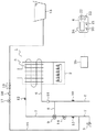
次に、本発明の一実施形態の給湯装置について図1に基づいて説明する。 Next, a hot water supply apparatus according to an embodiment of the present invention will be described with reference to FIG.
1は本実施形態の給湯装置、2は灯油等を燃料とし燃料を燃焼させて火炎を発生させる加熱手段としてバーナ、3は台所や洗面所等の所定箇所に設けられた給湯栓、4は給湯装置1を遠隔操作する操作手段としてのリモコンである。
DESCRIPTION OF
5はフィンアンドチューブ式の熱交換器、6は熱交換器5の上流に設けられ給水源から供給される水を熱交換器5に流通させる給水管、7は熱交換器5の下流に設けられ熱交換器5で加熱された湯を流通させ、終端に備えられた給湯栓3に湯を供給する給湯管、8は給水管6から分岐され、給水管6と給湯管7とを接続し熱交換器5をバイパスするバイパス管、9は給湯管7とバイパス管8との接続部に設けられ熱交換器5で加熱された湯とバイパス管8からの水とを混合する混合弁で、混合弁9は内部の弁体の弁開度を調整することで湯と水の混合比を調整した所望の温度の湯を出湯させるものである。なお、給水管6と給湯管7とバイパス管8とで給湯用の水が流通する給湯流路を構成するものである。
5 is a fin-and-tube heat exchanger, 6 is provided upstream of the
10は給水管6に設けられ給水の温度を検出する給水温度センサ、11は給水管6とバイパス管8との接続部よりも下流側の給水管6に設けられ熱交換器5に流入する水の流量を検出する流量検出手段としての流量センサ、12は給湯管7とバイパス管8との接続部よりも上流側の給湯管7に設けられた熱交出口温度検出手段としての熱交出口温度センサで、熱交出口温度センサ12は、熱交換器5から流出する湯の温度を検出するものである。13は混合弁9で混合された湯の温度を検出する出湯温度検出手段としての出湯温度センサ、14は給湯管7とバイパス管8との接続部(混合弁9接続位置)よりも下流側の給湯管7に設けられ出湯される流量を制御する流量調整手段としての水比例弁である。
A water
15は浴槽、16は混合弁9より下流側の給湯管7から分岐し浴槽15へ湯を供給する湯張り管で、湯張り管16には、湯張り管16を開閉する湯張り弁17と、浴槽15への時間当たりの湯張り流量を検出する風呂流量センサ18と、浴槽15からの浴槽水の逆流を防ぐ二重の逆止弁19とが設けられているものである。
15 is a bathtub, 16 is a hot water pipe that branches from the hot
前記リモコン4には、混合弁9から出湯させ給湯栓3へ供給させる湯温を設定する出湯温度設定手段としての給湯温度設定スイッチ20と、混合弁9から出湯させ湯張り管16を介して浴槽15へ供給する湯温を設定する出湯温度設定手段としての風呂温度設定スイッチ21と、浴槽15へ風呂設定温度の湯を設定された湯張り量注湯させて湯張りする湯張り運転の開始を指示する湯張りスイッチ22と、通常時よりもエネルギーを制限して省エネルギー運転を行うようエコモード設定するエコモード設定手段としてのエコモードスイッチ23と、給湯装置1の状態や、給湯温度設定スイッチ20で設定された出湯設定温度としての給湯設定温度、風呂温度設定スイッチ21で設定された出湯設定温度としての風呂設定温度、設定湯張り量、エコモードが設定されているか否かなどを表示する表示部24とが設けられているものである。なお、ユーザの選択操作によりエコモードスイッチ23がONされエコモードが設定された場合、リモコン4の表示部24に表示される給湯設定温度は変更されることなく、給湯栓3から出湯される湯温を給湯設定温度よりも所定温度(例えば1℃)低くしたり、リモコン4の表示部24に表示される風呂設定温度は変更されることなく、浴槽15に注湯される湯温を風呂設定温度よりも所定温度(例えば1℃)低くしたり、リモコン4の表示部24に表示される設定湯張り量は変更されることなく、浴槽15に注湯される設定湯張り量よりも所定量(例えば10L)少なくするというように、設定温度を低くして通常時よりも燃料量を低減させる、あるいは、湯張り量(水の使用量)を減らして、減量した分の水を加熱するのに必要な燃料量分を通常時よりも低減させる省エネな運転を行わせることができるものである。
The
25はマイクロコンピュータを主体として、給湯装置1の各センサからの信号やリモコン4からの信号を受け、各アクチュエータの駆動を制御する制御手段で、この制御手段25は、熱交換器5から流出させる湯の熱交出口目標温度を設定する機能を有しており、給湯温度設定スイッチ20または風呂温度設定スイッチ21で設定された設定温度の湯を出湯する場合、制御手段25は、熱交出口温度センサ12で検出される湯の温度が設定された熱交出口目標温度になるように、バーナ2の燃焼量を制御、すなわちバーナ2によって熱交換器5を流通する水へ与える加熱量を制御し、出湯温度センサ13で検出される湯の温度が給湯温度設定スイッチ20または風呂温度設定スイッチ21で設定された設定温度に基づく温度の湯となるように混合弁9の開度を制御するものである。なお、上記の給湯温度設定スイッチ20または風呂温度設定スイッチ21で設定された設定温度に基づく温度の湯とは、給湯設定温度の湯または風呂設定温度の湯の他に、エコモードが設定されていた場合の給湯設定温度よりも所定温度低い温度の湯または風呂設定温度よりも所定温度低い温度の湯を含むものである。
また、制御手段25は、給湯栓3からの出湯、あるいは浴槽15への湯張りを行う出湯動作中において、流量センサ11が給湯流路を構成する配管内に潰食を発生させるおそれがある所定流量以上を検出した場合、潰食防止制御を実行するものであり、潰食防止制御では、出湯動作中において流量センサ11が前記所定流量以上を検出したときに、エコモードスイッチ23がONされておらず、エコモードが設定されていない通常時の場合、制御手段25は、熱交出口目標温度をそれまで設定していた目標温度よりも高い目標温度に変更する一方、出湯動作中において流量センサ11が前記所定流量以上を検出したときに、ユーザの選択操作によりエコモードスイッチ23がONされてエコモードが設定されている場合、制御手段25は、水比例弁14の開度を閉じ方向に制御し出湯流量を制限するものである。上記潰食防止制御の詳細については後述する。
In addition, the control means 25 has a predetermined possibility that the
次に、この一実施形態の給湯装置1の出湯動作について、図2のフローチャートを用いて説明する。なお、ここでは、給湯栓3から出湯するための出湯動作についてのみ説明するものとし、浴槽15へ湯張りするための出湯動作については、出湯先が給湯栓3か浴槽15かの違いだけであるため、給湯栓3から出湯するための出湯動作と同様であるため説明を省略する。
Next, the hot water operation of the hot
今、適宜箇所の給湯栓3が開栓されて出湯が開始されると、この水の流れを流量センサ11が検知し、制御手段25は、流量センサ11の検出する流量に基づいて、流量センサ11の検出する検出流量が最低作動流量以上か否か判断し(ステップS1)、最低作動流量以上であると判断すると、燃焼要求ありとしてバーナ2の燃焼を開始させ、熱交換器5を流通する水を加熱するものである。この時、熱交換器5から流出させる湯の熱交出口目標温度は、リモコン4の給湯温度設定スイッチ20で設定された給湯設定温度(例えば40℃)よりも高温の予め定められた規定温度(例えば50℃)に設定され、熱交出口温度センサ12で検出される湯温が前記規定温度になるように、制御手段25がバーナ2の燃焼量を制御するものである。
Now, when the
そして、熱交換器5から流出した規定温度の湯とバイパス管8からの水とを混合弁9で混合し、制御手段25は、出湯温度センサ13で検出される湯温が給湯温度設定スイッチ20で設定された給湯設定温度になるように、混合弁9の開度を制御するものであり、出湯温度センサ13で検出される湯温が給湯設定温度より高い場合は、湯側を絞り、水側を開くように混合弁9内部の弁体の弁開度を調整して、給湯設定温度の湯を給湯栓3へ供給し出湯するものであり、出湯温度センサ13で検出される湯温が給湯設定温度より低い場合は、水側を絞り、湯側を開くように混合弁9内部の弁体の弁開度を調整して、給湯設定温度の湯を給湯栓3へ供給し出湯するものである。なお、上述の制御手段25による制御は、流量センサ11で検出される流量が最低作動流量以上且つ給湯流路を構成する配管内に潰食を発生させるおそれがある予め設定された潰食危険流量未満の範囲内であって、エコモードが設定されていない通常の出湯動作時に行われている制御であり、流量センサ11で検出される流量が最低作動流量以上且つ前記潰食危険流量未満の範囲内であって、エコモードが設定されている場合の出湯動作時には、相違点のみ示すと、制御手段25は、出湯温度センサ13で検出される湯温が給湯温度設定スイッチ20で設定された給湯設定温度よりも所定温度(例えば1℃)低い温度になるように、混合弁9の開度を制御して、通常時よりも省エネルギー運転を行うものである。
And the hot water of the specified temperature which flowed out from the
また、出湯動作中、制御手段25は、流量センサ11の検出する流量に基づいて、流量センサ11の検出する検出流量が潰食危険流量以上となったか否か判断し(ステップS2)、潰食危険流量以上となったと判断すると、制御手段25は、エコモードが設定されていないかどうか、すなわち、エコモードスイッチ23がONされていないかどうかを判断し(ステップS3)、エコモードが設定されていないと判断すると、制御手段25は、熱交出口目標温度をそれまでの熱交出口目標温度であった規定温度(50℃)から、規定温度よりも高い温度である潰食防止温度(例えば57℃)に熱交出口目標温度を変更するものである(ステップS4)。一方、前記ステップS3で、制御手段25が、エコモードが設定されている、すなわち、ユーザの選択操作によりエコモードスイッチ23がONされていると判断すると、水比例弁14をそれまでの開度よりも閉じる方向に制御し、出湯流量を制限するものである(ステップS5)。なお、前記ステップS2において、制御手段25は、流量センサ11の検出する検出流量が潰食危険流量以上となったか否かを判断したが、制御手段25は、流量センサ11の検出する検出流量が潰食危険流量以上となった状態を所定時間(例えば10秒)連続で検知したか否かを判断してもよいものである。
In addition, during the hot water operation, the control means 25 determines whether or not the detected flow rate detected by the
ここで、前記ステップS3の処理から前記ステップS4の処理に移行する潰食防止制御が行われた場合の給湯装置1の状態について、図3を用いて詳細に説明する。なお、前提として、給湯流路を構成する配管のうち、例えば熱交換器5を構成する配管の内径が最小でありその配管内径をφ14、給水温度15℃、熱交出口目標温度50℃、給湯設定温度40℃で出湯動作が行われているときに、流量センサ11で検出される検出流量が、潰食危険流量を超えた場合を想定するものとする。ここで挙げた数値はあくまで一例であり、特に限定されるものではない。
Here, the state of the hot
まず、図3に示すように、エコモードが設定されていない通常時の出湯動作中に、総流量が22L/minで、熱交換器5に流入する流量として、流量センサ11の検出する検出流量が15.7L/minであった場合、熱交換器5の配管内の流速は流量15.7L/minから換算して1.70m/sとなり、制御手段25は、検出流量が潰食危険流量を超えたものと判断し、熱交出口目標温度をそれまでの目標温度であった50℃から、潰食防止温度である57℃へと目標温度を高くするものである。ここで、潰食について補足説明すると、潰食とは流体が流通する配管内で発生する腐食現象で、流体の流速が速いときなどに、配管内表面が馬蹄形状にえぐられるように腐食するものであり、流速として1.5m/sを超えると潰食が発生する危険性が高まるものとされている。図3に示した給湯装置1においては、流量が13.8L/min(流速に換算すると約1.5m/s)を超えると、配管内径φ14の配管を有する熱交換器5の配管内で潰食が発生する危険性があるため、潰食危険流量として13.8L/minを予め記憶しておき、制御手段25は、流量センサ11で検出される流量と上記潰食危険流量とを比較し、潰食が発生するおそれがあるか否かの判断を行っている。なお、上記潰食危険流量は、給湯流路を構成する配管の配管内径(または流路断面積)と密接な関係があり、給湯流路を構成する配管の配管内径(または流路断面積)を考慮して定められるものである。
First, as shown in FIG. 3, the detected flow rate detected by the
そして、上述のように、熱交出口目標温度が50℃から57℃に変更されると、混合弁9で混合される湯側の温度が高くなるため、給湯設定温度40℃の湯を出湯するのに、湯側を絞り、水側を開くように混合弁9が制御され、熱交換器5を流通する水の流量が13.1L/min(流速に換算すると1.42m/s)に減少すると共にバイパス管8を流通する水の流量が8.9L/minに増えるものである。この時、水比例弁14の開度は潰食防止制御実施前後で変更されず出湯流量は22L/minのままであり、出湯流量が制限されることがないため、ユーザの利便性を損なうことがないものである。
As described above, when the heat exchange outlet target temperature is changed from 50 ° C. to 57 ° C., the hot water temperature mixed by the mixing
以上より、エコモードが設定されていない通常の出湯動作中において、流量センサ11の検出する検出流量が潰食危険流量に達した場合に、熱交出口目標温度を規定温度よりも高い温度である潰食防止温度に変更するようにしたことで、潰食が発生する危険がない流量では熱交出口目標温度を低く保って、バーナ2で消費される熱量を低減させて熱効率を向上させ、潰食が発生する危険がある流量以上に限って熱交出口目標温度を規定温度よりも高くすることで、給湯流路のうち、給水管6とバイパス管8の接続部よりも下流側の給水管6および熱交換器5および給湯管7とバイパス管8の接続部よりも上流側の給湯管7からなる湯側流路を流通する水または湯の流速が下がるので、潰食の発生を抑制することができるものであり、熱交出口目標温度の変更のみで出湯流量は変化しないことから、ユーザの利便性を損なうこともないものである。
As described above, the heat exchange outlet target temperature is higher than the specified temperature when the detected flow rate detected by the
また、熱交出口目標温度を潰食防止温度に変更した場合には、制御手段25は、その回の出湯動作が停止されるまでは熱交出口目標温度を潰食防止温度に維持するようにしてもよく、この場合、出湯動作中に何度も熱交出口目標温度が変更されることがないので、温調性能が乱れることなく温度変動の少ない快適な出湯を行うことができるものである。 In addition, when the heat exchange outlet target temperature is changed to the erosion prevention temperature, the control means 25 maintains the heat exchange outlet target temperature at the erosion prevention temperature until the time of the hot water discharge operation is stopped. In this case, since the heat exchange outlet target temperature is not changed many times during the hot water operation, it is possible to perform a comfortable hot water with little temperature fluctuation without disturbing the temperature control performance. .
さらに、熱交出口目標温度を潰食防止温度に変更した回の出湯が停止した場合、制御手段25は、熱交出口目標温度を元の温度である規定温度に戻すようにしてもよく、この場合、次回の出湯動作開始時において、潰食の危険がない流量域にて熱効率のよい出湯を行うことができるものである。 Further, when the hot water outlet at the time when the heat exchange outlet target temperature is changed to the erosion prevention temperature is stopped, the control means 25 may return the heat exchange outlet target temperature to the original temperature which is the original temperature. In this case, at the start of the next hot-water operation, hot water with high thermal efficiency can be performed in a flow rate region where there is no risk of erosion.
なお、本実施形態では、前記潰食防止温度を固定の57℃としているが、流量センサ11で検出される検出流量に応じた潰食防止温度を設定できるようなものであってもよく、例えば、検出流量が13.8L/min〜16L/min未満の範囲内の場合は潰食防止温度を57℃、検出流量が16L/min〜18L/min未満の範囲内の場合は潰食防止温度を60℃とするなど、制御手段25は、流量センサ11で検出される検出流量が大きいほど潰食防止温度を高く設定するようにすることで、流量に見合った適切な潰食防止温度を設定でき、潰食の発生を抑制しつつ、熱交出口目標温度上昇に伴う熱効率の悪化をできるだけ抑制することができるものである。
In the present embodiment, the erosion prevention temperature is fixed at 57 ° C., however, the erosion prevention temperature may be set according to the detected flow rate detected by the
次に、前記ステップS3の処理から前記ステップS5の処理に移行する潰食防止制御が行われた場合の給湯装置1の状態について、図4を用いて詳細に説明する。なお、前提として、給湯流路を構成する配管のうち、例えば熱交換器5を構成する配管の内径が最小でありその配管内径をφ14、給水温度15℃、熱交出口目標温度50℃、給湯設定温度40℃で出湯動作が行われているときに、流量センサ11で検出される検出流量が、潰食危険流量を超えた場合を想定するものとする。ここで挙げた数値はあくまで一例であり、特に限定されるものではない。なお、ここではエコモードが設定されているため、リモコン4の表示部24に表示されている給湯設定温度は40℃だが、制御上は給湯設定温度は39℃で制御されるものとする。
Next, the state of the hot
まず、ユーザの選択操作によりエコモードが設定されたエコモード時の出湯動作中に、総流量が22L/minで、熱交換器5に流入する流量として、流量センサ11の検出する検出流量が15.1L/minであった場合、熱交換器5の配管内の流速は流量15.1L/minから換算して1.64m/sとなり、制御手段25は、検出流量が潰食危険流量を超えたものと判断し、水比例弁14の開度を、それまでの開度から流量センサ11で検出される検出流量が潰食危険流量を下回るまで閉じる方向に制御し(ただし、全閉を除く)、出湯流量を制限するものである。
First, the detected flow rate detected by the
そして、上述のように、水比例弁14の開度が閉じる方向に制御されると、出湯流量(総流量)が22L/minから19L/minに制限され、熱交換器5を流通する水の流量が13.0L/min(流速に換算すると1.41m/s)に減少するものである。この時、熱交出口目標温度は潰食防止制御実施前後で変更されず50℃のままであり、熱交出口目標温度を上げた場合に比べて熱効率がよいものである。
And as mentioned above, when the opening degree of the water
以上より、エコモード設定時の出湯動作中において、流量センサ11の検出する検出流量が潰食危険流量に達した場合に、水比例弁14の開度をそれまでの開度よりも閉じる方向に制御するようにしたことで、潰食が発生する危険がない流量域では水比例弁14の開度を変更せずそのままの開度とするので、必要以上に出湯流量が制限されることがなくユーザの利便性を損なうことがないものであり、潰食が発生する危険がある流量以上に限って水比例弁14の開度をそれまでの開度よりも閉じる方向に制御することで、出湯流量が制限され、前記湯側流路を流通する水または湯の流速が下がるので、潰食の発生を抑制することができ、水比例弁14の開度の変更のみで熱交出口目標温度は変化しないことから、熱効率の良い状態での出湯が可能である。また、潰食が発生する危険がある流量以上を検出した場合に限って出湯流量が制限されるが、ユーザは意識的に省エネルギーな運転をさせようとエコモード設定にするものであるから、出湯流量の制限が節水という省エネ機能として認識され、利便性の損失はある程度許容されるものである。
As described above, when the detected flow rate detected by the
また、エコモード設定時の出湯動作中において、水比例弁14の開度をそれまでの開度よりも閉じる方向に制御した後、その回の出湯動作中に、流量センサ11の検出流量が潰食危険流量から乖離する方向に小さくなり、水比例弁14の開度を閉じる方向に制御する前の元の開度に戻しても潰食危険流量未満であることが、制御手段25にて演算等により判断される場合は、制御手段25は、水比例弁14の開度を元の開度に戻すようにしてもよく、この場合、エコモード設定時の出湯動作中であっても、必要のない場合は、出湯流量が制限されることがないので、ユーザの利便性を損なうことがないものである。
In addition, during the hot water operation when the eco mode is set, after the opening degree of the water
さらに、エコモード設定時の出湯動作中において、水比例弁14の開度をそれまでの開度よりも閉じる方向に制御した回の出湯が停止した場合、制御手段25は、水比例弁14の開度を閉じる方向に制御する前の元の開度に戻すようにしてもよく、この場合、次回の出湯動作開始時において、潰食の危険がない流量域にて出湯流量が制限されることがなく、ユーザの利便性を損なうことがないものである。
Furthermore, during the hot water supply operation when the eco mode is set, when the hot water is stopped in a time when the opening of the water
なお、本発明は先に説明した一実施形態に限定されるものではなく、本実施形態では、給湯栓3からの出湯および浴槽15への湯張りを行える給湯装置1において本発明を適用したが、給湯のみが行える単機能の給湯装置1において本発明を適用してもよく、浴槽水の追い焚き機能が付いた給湯装置1において本発明を適用してもよいものである。
The present invention is not limited to the above-described embodiment. In the present embodiment, the present invention is applied to the hot
また、本実施形態では、熱交換器5を流通する水を加熱する加熱手段として燃焼式のバーナ2を用いたが、熱交換器5を流通する水を加熱する加熱手段はヒートポンプ式の加熱手段であってもよく、特に限定されるものではない。
In this embodiment, the
また、本実施形態では、エコモードが設定された場合、リモコン4の表示部24に表示される給湯設定温度は変更されることなく、給湯栓3から出湯される湯温を給湯設定温度よりも所定温度低くしたり、リモコン4の表示部24に表示される風呂設定温度は変更されることなく、浴槽15に注湯される湯温を風呂設定温度よりも所定温度低くしたり、リモコン4の表示部24に表示される設定湯張り量は変更されることなく、浴槽15に注湯される設定湯張り量よりも所定量少なくするという省エネな運転を行える制御例を挙げたが、これらだけに限定されるものではなく、通常時よりも燃料や水の使用量を低減させる省エネな運転を行わせることができるものであればよいものである。
In the present embodiment, when the eco mode is set, the hot water supply set temperature displayed on the
1 給湯装置
2 バーナ
5 熱交換器
6 給水管
7 給湯管
8 バイパス管
9 混合弁
11 流量センサ
14 水比例弁
20 給湯温度設定スイッチ
21 風呂温度設定スイッチ
23 エコモードスイッチ
25 制御手段
DESCRIPTION OF
Claims (4)
Priority Applications (1)
| Application Number | Priority Date | Filing Date | Title |
|---|---|---|---|
| JP2017130899A JP6904815B2 (en) | 2017-07-04 | 2017-07-04 | Hot water heater |
Applications Claiming Priority (1)
| Application Number | Priority Date | Filing Date | Title |
|---|---|---|---|
| JP2017130899A JP6904815B2 (en) | 2017-07-04 | 2017-07-04 | Hot water heater |
Publications (2)
| Publication Number | Publication Date |
|---|---|
| JP2019015419A true JP2019015419A (en) | 2019-01-31 |
| JP6904815B2 JP6904815B2 (en) | 2021-07-21 |
Family
ID=65357305
Family Applications (1)
| Application Number | Title | Priority Date | Filing Date |
|---|---|---|---|
| JP2017130899A Active JP6904815B2 (en) | 2017-07-04 | 2017-07-04 | Hot water heater |
Country Status (1)
| Country | Link |
|---|---|
| JP (1) | JP6904815B2 (en) |
-
2017
- 2017-07-04 JP JP2017130899A patent/JP6904815B2/en active Active
Also Published As
| Publication number | Publication date |
|---|---|
| JP6904815B2 (en) | 2021-07-21 |
Similar Documents
| Publication | Publication Date | Title |
|---|---|---|
| EP2313694B1 (en) | Method for controlling a hot water temperature in using low flux in hot water supply system | |
| KR101467095B1 (en) | Hot water supply system | |
| JP5200842B2 (en) | Water heater | |
| US10824178B2 (en) | Heating and hot water supply apparatus and control method thereof | |
| CA2754683A1 (en) | Hot-water supply system | |
| CN111426052A (en) | Constant-temperature gas water heater and control method thereof | |
| KR101482847B1 (en) | Hot water supply system | |
| JP2019007687A (en) | Hot water system | |
| KR20190128577A (en) | Boiler for heating and hot-water supply and control method thereof | |
| JP6376390B2 (en) | Hot water storage hot water system | |
| JP6350968B2 (en) | Hot water storage system | |
| JP2009270751A (en) | Hot water supply device | |
| JP5836794B2 (en) | Hot water storage system | |
| JP2019015419A (en) | Hot water supply device | |
| JP5505129B2 (en) | Hot water system | |
| JP2010210178A (en) | Hot water supply system | |
| JP3876877B2 (en) | Gas hot water heater | |
| JP5388608B2 (en) | Hot water storage water heater | |
| JP2007003057A (en) | Hot water storage water heater | |
| JP2005106330A (en) | Hot water supply apparatus and control method thereof | |
| JP6376388B2 (en) | Hot water mixing device | |
| JP5870844B2 (en) | Hot water storage water heater | |
| JP2003269795A (en) | Preheating water supply type hot water supply control method and preheating water supply type hot water supply system | |
| JP6998783B2 (en) | Immediate hot water discharge device | |
| JP4029249B2 (en) | Circulating water heating control method and circulating water heating control device |
Legal Events
| Date | Code | Title | Description |
|---|---|---|---|
| A621 | Written request for application examination |
Free format text: JAPANESE INTERMEDIATE CODE: A621 Effective date: 20191217 |
|
| A977 | Report on retrieval |
Free format text: JAPANESE INTERMEDIATE CODE: A971007 Effective date: 20201116 |
|
| A131 | Notification of reasons for refusal |
Free format text: JAPANESE INTERMEDIATE CODE: A131 Effective date: 20201208 |
|
| TRDD | Decision of grant or rejection written | ||
| A01 | Written decision to grant a patent or to grant a registration (utility model) |
Free format text: JAPANESE INTERMEDIATE CODE: A01 Effective date: 20210622 |
|
| A61 | First payment of annual fees (during grant procedure) |
Free format text: JAPANESE INTERMEDIATE CODE: A61 Effective date: 20210624 |
|
| R150 | Certificate of patent or registration of utility model |
Ref document number: 6904815 Country of ref document: JP Free format text: JAPANESE INTERMEDIATE CODE: R150 |
|
| R250 | Receipt of annual fees |
Free format text: JAPANESE INTERMEDIATE CODE: R250 |