JP6972660B2 - Idle tone disperser and frequency ratio measuring device - Google Patents
Idle tone disperser and frequency ratio measuring device Download PDFInfo
- Publication number
- JP6972660B2 JP6972660B2 JP2017105463A JP2017105463A JP6972660B2 JP 6972660 B2 JP6972660 B2 JP 6972660B2 JP 2017105463 A JP2017105463 A JP 2017105463A JP 2017105463 A JP2017105463 A JP 2017105463A JP 6972660 B2 JP6972660 B2 JP 6972660B2
- Authority
- JP
- Japan
- Prior art keywords
- signal
- output
- frequency
- jitter
- measured
- Prior art date
- Legal status (The legal status is an assumption and is not a legal conclusion. Google has not performed a legal analysis and makes no representation as to the accuracy of the status listed.)
- Active
Links
Images
Classifications
-
- H—ELECTRICITY
- H03—ELECTRONIC CIRCUITRY
- H03M—CODING; DECODING; CODE CONVERSION IN GENERAL
- H03M3/00—Conversion of analogue values to or from differential modulation
- H03M3/30—Delta-sigma modulation
- H03M3/322—Continuously compensating for, or preventing, undesired influence of physical parameters
- H03M3/368—Continuously compensating for, or preventing, undesired influence of physical parameters of noise other than the quantisation noise already being shaped inherently by delta-sigma modulators
- H03M3/37—Compensation or reduction of delay or phase error
- H03M3/372—Jitter reduction
-
- G—PHYSICS
- G01—MEASURING; TESTING
- G01R—MEASURING ELECTRIC VARIABLES; MEASURING MAGNETIC VARIABLES
- G01R23/00—Arrangements for measuring frequencies; Arrangements for analysing frequency spectra
- G01R23/005—Circuits for comparing several input signals and for indicating the result of this comparison, e.g. equal, different, greater, smaller (comparing phase or frequency of 2 mutually independent oscillations in demodulators)
-
- H—ELECTRICITY
- H03—ELECTRONIC CIRCUITRY
- H03M—CODING; DECODING; CODE CONVERSION IN GENERAL
- H03M3/00—Conversion of analogue values to or from differential modulation
- H03M3/30—Delta-sigma modulation
- H03M3/322—Continuously compensating for, or preventing, undesired influence of physical parameters
- H03M3/324—Continuously compensating for, or preventing, undesired influence of physical parameters characterised by means or methods for compensating or preventing more than one type of error at a time, e.g. by synchronisation or using a ratiometric arrangement
- H03M3/326—Continuously compensating for, or preventing, undesired influence of physical parameters characterised by means or methods for compensating or preventing more than one type of error at a time, e.g. by synchronisation or using a ratiometric arrangement by averaging out the errors
- H03M3/328—Continuously compensating for, or preventing, undesired influence of physical parameters characterised by means or methods for compensating or preventing more than one type of error at a time, e.g. by synchronisation or using a ratiometric arrangement by averaging out the errors using dither
- H03M3/3283—Continuously compensating for, or preventing, undesired influence of physical parameters characterised by means or methods for compensating or preventing more than one type of error at a time, e.g. by synchronisation or using a ratiometric arrangement by averaging out the errors using dither the dither being in the time domain
-
- H—ELECTRICITY
- H03—ELECTRONIC CIRCUITRY
- H03M—CODING; DECODING; CODE CONVERSION IN GENERAL
- H03M3/00—Conversion of analogue values to or from differential modulation
- H03M3/30—Delta-sigma modulation
- H03M3/322—Continuously compensating for, or preventing, undesired influence of physical parameters
- H03M3/324—Continuously compensating for, or preventing, undesired influence of physical parameters characterised by means or methods for compensating or preventing more than one type of error at a time, e.g. by synchronisation or using a ratiometric arrangement
- H03M3/346—Continuously compensating for, or preventing, undesired influence of physical parameters characterised by means or methods for compensating or preventing more than one type of error at a time, e.g. by synchronisation or using a ratiometric arrangement by suppressing active signals at predetermined times, e.g. muting, using non-overlapping clock phases
-
- H—ELECTRICITY
- H03—ELECTRONIC CIRCUITRY
- H03M—CODING; DECODING; CODE CONVERSION IN GENERAL
- H03M3/00—Conversion of analogue values to or from differential modulation
- H03M3/30—Delta-sigma modulation
-
- H—ELECTRICITY
- H03—ELECTRONIC CIRCUITRY
- H03M—CODING; DECODING; CODE CONVERSION IN GENERAL
- H03M3/00—Conversion of analogue values to or from differential modulation
- H03M3/30—Delta-sigma modulation
- H03M3/458—Analogue/digital converters using delta-sigma modulation as an intermediate step
- H03M3/466—Multiplexed conversion systems
- H03M3/472—Shared, i.e. using a single converter for multiple channels
Landscapes
- Engineering & Computer Science (AREA)
- Theoretical Computer Science (AREA)
- Physics & Mathematics (AREA)
- General Physics & Mathematics (AREA)
- Measuring Frequencies, Analyzing Spectra (AREA)
- Compression, Expansion, Code Conversion, And Decoders (AREA)
Description
本発明は、アイドルトーン分散装置および周波数比計測装置に関するものである。 The present invention relates to an idle tone dispersion device and a frequency ratio measuring device.
基準信号(基準クロック)の周波数と被測定信号の周波数との比に対応する信号を生成する周波数比測定装置(周波数カウンター)が知られている。 A frequency ratio measuring device (frequency counter) that generates a signal corresponding to the ratio of the frequency of the reference signal (reference clock) to the frequency of the measured signal is known.
例えば、特許文献1には、基準信号と被測定信号とのいずれか一方を用いて他方を周波数デルタシグマ変調してアイドルトーンを分散させた周波数デルタシグマ変調信号を出力するアイドルトーン分散装置が開示されている。特許文献1に記載されたアイドルトーン分散装置は、並列に接続された複数の周波数デルタシグマ変調部(以下、「FDSM(Frequency Delta Sigma Modulator)」と言う)と、各周波数デルタシグマ変調部の出力信号を加算して周波数デルタシグマ変調信号を出力する加算部とを備えている。各FDSMには、互いに位相の異なる被測定信号および位相が同一の基準信号、または、互いに位相の異なる基準信号および位相が同一の被測定信号、または、互いに位相の異なる被測定信号および互いに位相の異なる基準信号が入力される。このアイドルトーン分散装置によれば、アイドルトーンを時間的に分散させ、アイドルトーンの影響を抑制することができる。
For example,
しかし、特許文献1に記載のアイドルトーン分散装置では、FDSMの並列数を増やしていくと、遅延量の余裕が少なくなり、アイドルトーンを時間的に分散させてアイドルトーンの影響を効果的に抑制することが困難となる。
本発明の目的は、周波数デルタシグマ変調で発生するアイドルトーンに起因する量子化雑音を抑制することができるアイドルトーン分散装置および周波数比計測装置を提供することにある。
However, in the idle tone disperser described in
An object of the present invention is to provide an idle tone dispersion device and a frequency ratio measuring device capable of suppressing the quantization noise caused by the idle tone generated by the frequency delta sigma modulation.
本発明は、上述の課題の少なくとも一部を解決するためになされたものであり、以下の形態または適用例として実現することが可能である。 The present invention has been made to solve at least a part of the above-mentioned problems, and can be realized as the following form or application example.
本発明のアイドルトーン分散装置は、基準信号と被測定信号とのいずれか一方を用いて他方を周波数デルタシグマ変調してアイドルトーンを分散させた周波数デルタシグマ変調信号を出力するアイドルトーン分散装置であって、
n(nは2以上の任意の自然数)個の周波数デルタシグマ変調部と、
前記n個の周波数デルタシグマ変調部の出力信号を加算して前記周波数デルタシグマ変調信号を出力する加算部と、を備え、
前記n個の周波数デルタシグマ変調部の各々は、前記基準信号と前記被測定信号とのいずれか一方を用いて他方を周波数デルタシグマ変調し、
前記基準信号と前記被測定信号との少なくとも一方は、前記周波数デルタシグマ変調部の出力信号のアイドルトーンの周波数よりも高い周波数成分を含むジッターを有することを特徴とする。
The idle tone disperser of the present invention is an idle tone disperser that outputs a frequency delta sigma modulated signal in which one of a reference signal and a measured signal is used and the other is frequency delta sigma-modulated to disperse the idle tone. There,
With n (n is an arbitrary natural number of 2 or more) frequency delta-sigma modulators,
It is provided with an adder that adds the output signals of the n frequency delta-sigma modulators and outputs the frequency delta-sigma modulation signal.
Each of the n frequency delta sigma modulators uses one of the reference signal and the measured signal to perform frequency delta sigma modulation on the other.
At least one of the reference signal and the measured signal is characterized by having a jitter containing a frequency component higher than the frequency of the idle tone of the output signal of the frequency delta sigma modulator.
このような本発明のアイドルトーン分散装置によれば、周波数デルタシグマ変調で発生する周期的な量子化雑音であるアイドルトーンを時間的に分散させ、アイドルトーンの影響を抑制することができる。特に、基準信号と被測定信号との少なくとも一方がアイドルトーンの周波数よりも高い周波数成分を含むジッターを有することにより、アイドルトーンに起因する量子化雑音の影響を大幅に抑制することができる。 According to such an idle tone disperser of the present invention, it is possible to temporally disperse the idle tone, which is periodic quantization noise generated by frequency delta-sigma modulation, and suppress the influence of the idle tone. In particular, since at least one of the reference signal and the measured signal has a jitter containing a frequency component higher than the frequency of the idle tone, the influence of the quantization noise caused by the idle tone can be significantly suppressed.
本発明のアイドルトーン分散装置は、基準信号と被測定信号とのいずれか一方を用いて他方を周波数デルタシグマ変調してアイドルトーンを分散させた周波数デルタシグマ変調信号を出力するアイドルトーン分散装置であって、
n(nは2以上の任意の自然数)個の周波数デルタシグマ変調部と、
前記被測定信号と前記基準信号との位相を調整して、n組の出力被測定信号および出力基準信号を生成して、各組の前記出力被測定信号および前記出力基準信号を前記n個の周波数デルタシグマ変調部の各々に供給する位相調整部と、
前記n個の周波数デルタシグマ変調部の出力信号を加算して前記周波数デルタシグマ変調信号を出力する加算部と、を備え、
前記位相調整部は、前記n個の周波数デルタシグマ変調部のうちの少なくとも一部の前記周波数デルタシグマ変調部の出力信号のアイドルトーンの位相が互いに異なるように、前記被測定信号と前記基準信号との位相を調整して、前記n組の出力被測定信号および出力基準信号を生成し、
前記n個の周波数デルタシグマ変調部の各々は、前記位相調整部から供給される前記出力基準信号と前記出力被測定信号とのいずれか一方を用いて他方を周波数デルタシグマ変調し、
前記出力基準信号と前記出力被測定信号とのうちの少なくとも1つは、前記アイドルトーンの周波数よりも高い周波数成分を含むジッターを有することを特徴とする。
The idle tone disperser of the present invention is an idle tone disperser that outputs a frequency delta sigma modulated signal in which one of a reference signal and a measured signal is used and the other is frequency delta sigma-modulated to disperse the idle tone. There,
With n (n is an arbitrary natural number of 2 or more) frequency delta-sigma modulators,
By adjusting the phase of the measured signal and the reference signal, n sets of output measured signals and output reference signals are generated, and each set of the output measured signals and the output reference signals is combined with the n sets of the output measured signals and the output reference signals. A phase adjuster that supplies each of the frequency delta sigma modulators,
It is provided with an adder that adds the output signals of the n frequency delta-sigma modulators and outputs the frequency delta-sigma modulation signal.
The phase adjusting unit has the measured signal and the reference signal so that the phases of the idle tones of the output signals of at least a part of the n frequency delta sigma modulators are different from each other. By adjusting the phase with and, the n sets of output measured signals and output reference signals are generated.
Each of the n frequency delta sigma modulators uses one of the output reference signal and the output measured signal supplied from the phase adjuster to perform frequency delta sigma modulation of the other.
At least one of the output reference signal and the output measured signal is characterized by having a jitter containing a frequency component higher than the frequency of the idle tone.
このような本発明のアイドルトーン分散装置によれば、周波数デルタシグマ変調で発生する周期的な量子化雑音であるアイドルトーンを時間的に分散させ、アイドルトーンの影響を抑制することができる。特に、基準信号と、被測定信号と、出力基準信号と、出力被測定信号とのうちの少なくとも1つがアイドルトーンの周波数よりも高い周波数成分を含むジッターを有することにより、アイドルトーンに起因する量子化雑音の影響を大幅に抑制することができる。 According to such an idle tone disperser of the present invention, it is possible to temporally disperse the idle tone, which is periodic quantization noise generated by frequency delta-sigma modulation, and suppress the influence of the idle tone. In particular, the quantum resulting from the idle tone by having at least one of the reference signal, the measured signal, the output reference signal, and the output measured signal having a jitter containing a frequency component higher than the frequency of the idle tone. The influence of noise can be significantly suppressed.
本発明のアイドルトーン分散装置では、所定時間をD、前記被測定信号の1周期または前記基準信号の1周期をT、mをn以下の任意の自然数、mD/nTを整数、mD/nTとmとが互いに素、i(iはn−1以下の任意の自然数)番目の周波数デルタシグマ変調部に供給する出力被測定信号と出力基準信号との位相差をPiとしたとき、
前記位相調整部は、D/n=Pi+1−Piとなるように、前記被測定信号と前記基準信号との位相を調整して、前記n組の出力被測定信号および出力基準信号を生成することが好ましい。
これにより、n個の周波数デルタシグマ変調部の出力信号のアイドルトーンの位相が互いに異なるようになるので、アイドルトーンを適確に時間的に分散させることができ、アイドルトーンの影響を抑制することができる。
In the idle tone disperser of the present invention, a predetermined time is D, one cycle of the measured signal or one cycle of the reference signal is T, m is an arbitrary natural number of n or less, mD / nT is an integer, and mD / nT. prime and a m, i (i is smaller than n-1 of an arbitrary natural number) when the phase difference between the second output signal to be measured is supplied to a frequency delta-sigma modulation of an output reference signal P i,
The phase adjusting unit adjusts the phase of the measured signal and the reference signal so that D / n = Pi + 1 −P i, and generates the n sets of output measured signals and the output reference signal. It is preferable to do so.
As a result, the phases of the idle tones of the output signals of the n frequency delta-sigma modulators are different from each other, so that the idle tones can be appropriately dispersed in time and the influence of the idle tones can be suppressed. Can be done.
本発明のアイドルトーン分散装置では、前記位相調整部は、前記n個の周波数デルタシグマ変調部のうちの一部の前記周波数デルタシグマ変調部の出力信号のアイドルトーンの位相が互いに異なるように、前記被測定信号と前記基準信号との位相を調整して、前記n組の出力被測定信号および出力基準信号を生成することが好ましい。
これにより、アイドルトーンを適確に時間的に分散させることができ、アイドルトーンの影響を抑制することができる。
In the idle tone disperser of the present invention, the phase adjusting unit has such that the phases of the idle tones of the output signals of some of the n frequency delta sigma modulators among the n frequency delta sigma modulators are different from each other. It is preferable to adjust the phases of the measured signal and the reference signal to generate the n sets of output measured signals and the output reference signal.
As a result, the idle tone can be appropriately dispersed in time, and the influence of the idle tone can be suppressed.
本発明のアイドルトーン分散装置では、所定時間をD、前記被測定信号の1周期または前記基準信号の1周期をT、mをn以下の任意の自然数、mD/nTを整数、mD/nTとmとが互いに素、i(iはn−1以下の任意の自然数)番目の周波数デルタシグマ変調部に供給する出力被測定信号と出力基準信号との位相差をPiとしたとき、
D/n≠Pi+1−Piであることが好ましい。
D/n≠Pi+1−Piであってもn個の周波数デルタシグマ変調部の出力信号のアイドルトーンの位相が互いに異なるようにすることができる。これによって、アイドルトーンを適確に時間的に分散させることができ、アイドルトーンの影響を抑制することができる。
また、遅延量の設定の自由度が高まり、調整が簡易になり、調整が簡易になることから特別な装置を必要とせず、製造コストを低減することができる。
In the idle tone disperser of the present invention, a predetermined time is D, one cycle of the measured signal or one cycle of the reference signal is T, m is an arbitrary natural number of n or less, mD / nT is an integer, and mD / nT. prime and a m, i (i is smaller than n-1 of an arbitrary natural number) when the phase difference between the second output signal to be measured is supplied to a frequency delta-sigma modulation of an output reference signal P i,
It is preferable that D / n ≠ Pi + 1 −P i.
Even if D / n ≠ Pi + 1 −P i , the phases of the idle tones of the output signals of the n frequency delta-sigma modulators can be made different from each other. As a result, the idle tone can be appropriately dispersed in time, and the influence of the idle tone can be suppressed.
In addition, the degree of freedom in setting the delay amount is increased, the adjustment is simplified, and the adjustment is simplified, so that no special device is required and the manufacturing cost can be reduced.
本発明のアイドルトーン分散装置では、前記ジッターは、前記アイドルトーンが有する周波数成分のうち、強度の最も大きい成分の周波数よりも高い周波数成分を含むことが好ましい。
これにより、アイドルトーンに起因する量子化雑音の影響を大幅に抑制することができる。
In the idle tone disperser of the present invention, it is preferable that the jitter contains a frequency component higher than the frequency of the component having the highest intensity among the frequency components of the idle tone.
As a result, the influence of the quantization noise caused by the idle tone can be significantly suppressed.
本発明のアイドルトーン分散装置では、前記ジッターを生成するジッター生成部を有することが好ましい。
これにより、別途、ジッターを生成する装置を用意する必要がなく、ジッターを付加したい信号に対し、容易かつ適確にジッターを付加することができる。
The idle tone disperser of the present invention preferably has a jitter generator that generates the jitter.
As a result, it is not necessary to separately prepare a device for generating jitter, and it is possible to easily and accurately add jitter to a signal to which jitter is to be added.
本発明のアイドルトーン分散装置では、前記ジッターの大きさは、前記基準信号の周波数、前記被測定信号の周波数、前記被測定信号の測定帯域および前記周波数デルタシグマ変調部の個数のうちの少なくとも1つに基づいて決定されることが好ましい。
これにより、適確にジッターの周波数帯域を設定することができる。
In the idle tone disperser of the present invention, the magnitude of the jitter is at least one of the frequency of the reference signal, the frequency of the signal to be measured, the measurement band of the signal to be measured, and the number of frequency delta sigma modulators. It is preferable to determine based on the above.
This makes it possible to accurately set the jitter frequency band.
本発明の周波数比計測装置は、本発明のアイドルトーン分散装置を備え、
前記被測定信号と前記基準信号との周波数比を測定することを特徴とする。
このような本発明の周波数比計測装置によれば、アイドルトーンに起因する量子化雑音の影響を抑制することができ、これにより、測定精度を向上させることができる。
The frequency ratio measuring device of the present invention includes the idle tone disperser of the present invention.
It is characterized in that the frequency ratio between the measured signal and the reference signal is measured.
According to such a frequency ratio measuring device of the present invention, the influence of the quantization noise caused by the idle tone can be suppressed, and thereby the measurement accuracy can be improved.
以下、本発明のアイドルトーン分散装置および周波数比計測装置を添付図面に示す実施形態に基づいて詳細に説明する。 Hereinafter, the idle tone dispersion device and the frequency ratio measuring device of the present invention will be described in detail based on the embodiments shown in the accompanying drawings.
<第1実施形態>
図1は、本発明のアイドルトーン分散装置の第1実施形態を示すブロック図である。図2は、図1に示すアイドルトーン分散装置のジッター加算器の構成例を示すブロック図である。図3は、図2に示すジッター加算器の動作を説明するためのタイミングチャートである。図4は、図1に示すアイドルトーン分散装置のジッター加算器の構成例を示すブロック図である。図10は、周波数デルタシグマ変調部の構成例を示すブロック図である。
<First Embodiment>
FIG. 1 is a block diagram showing a first embodiment of the idle tone dispersion device of the present invention. FIG. 2 is a block diagram showing a configuration example of a jitter adder of the idle tone disperser shown in FIG. FIG. 3 is a timing chart for explaining the operation of the jitter adder shown in FIG. FIG. 4 is a block diagram showing a configuration example of a jitter adder of the idle tone disperser shown in FIG. 1. FIG. 10 is a block diagram showing a configuration example of the frequency delta sigma modulation unit.
なお、図面には、被測定信号を「Fx」と記載し、基準信号を「Fc」と記載し、出力被測定信号を「Fx1」、「Fx2」、「Fxj」、「Fxn」と記載し、出力基準信号を「Fc1」、「Fc2」、「Fcj」、「Fcn」と記載し、また、「1」、「2」、「j」、「n」等の添え字を付して互いを区別する。また、本実施形態の説明でも、被測定信号を「Fx」と記載し、基準信号を「Fc」と記載し、出力被測定信号を「Fx1」、「Fx2」、「Fxj」、「Fxn」と記載し、出力基準信号を「Fc1」、「Fc2」、「Fcj」、「Fcn」と記載し、また、「1」、「2」、「j」、「n」等の添え字を付して互いを区別するが、一部では、その記載を省略する。 In the drawings, the measured signal is described as "Fx", the reference signal is described as "Fc", and the output measured signal is described as "Fx1", "Fx2", "Fxj", and "Fxn". , Output reference signals are described as "Fc1", "Fc2", "Fcj", "Fcn", and each other with subscripts such as "1", "2", "j", "n". To distinguish. Further, in the description of the present embodiment, the measured signal is described as "Fx", the reference signal is described as "Fc", and the output measured signal is described as "Fx1", "Fx2", "Fxj", "Fxn". , And the output reference signal is described as "Fc1", "Fc2", "Fcj", "Fcn", and with subscripts such as "1", "2", "j", "n". However, the description is omitted in some cases.
また、以下の説明では、位相調整部10から出力された基準信号(位相調整部10により位相が調整された基準信号)は、「出力基準信号」または「基準信号」と言う。同様に、位相調整部10から出力された被測定信号(位相調整部10により位相が調整された被測定信号)は、「出力被測定信号」または「被測定信号」と言う。
また、信号のレベルが「ロー(Low)」の場合を「0」、信号のレベルが「ハイ(High)」の場合を「1」とも言う。これらは、他の実施形態でも同様である。
Further, in the following description, the reference signal output from the phase adjusting unit 10 (reference signal whose phase is adjusted by the phase adjusting unit 10) is referred to as an "output reference signal" or a "reference signal". Similarly, the measured signal output from the phase adjusting unit 10 (the measured signal whose phase is adjusted by the phase adjusting unit 10) is referred to as an “output measured signal” or a “measured signal”.
Further, the case where the signal level is "Low" is also referred to as "0", and the case where the signal level is "High" is also referred to as "1". These are the same in other embodiments.
図1に示すように、アイドルトーン分散装置1は、被測定信号Fxと基準信号Fcとの位相を調整して、n(nは2以上の自然数)組の出力被測定信号Fx1(被測定信号)〜出力被測定信号Fxn(被測定信号)および出力基準信号Fc1(基準信号)〜出力基準信号Fcn(基準信号)を出力する位相調整部10と、n個(複数)の周波数デルタシグマ変調部20(以下、「FDSM(Frequency Delta Sigma Modulator)」と言う)と、加算器30と、ジッター加算器5(ジッター生成部)とを備えている。
また、ジッター加算器5の数は、1つでもよく、また、複数でもよいが、本実施形態では、ジッター加算器5は、複数設けられている。なお、ジッター加算器5については、後に詳述する。
As shown in FIG. 1, the
Further, the number of the
また、各FDSM20は、並列に接続されている。また、各FDSM20は、位相調整部10の出力側(後段)に接続され、加算器30は、各FDSM20の出力側に接続されている。また、FDSM20の数は、複数であれば特に限定されないが、その上限は、例えば、5000程度とすることができる。また、位相調整部10には、基準信号および被測定信号が入力される。また、被測定信号とは、測定の対象となる信号である。また、基準信号とは、周波数が既知の信号であり、測定の基準となる信号である。また、図面中の添え字「1」、「2」、「j」、「n」は、それぞれ、「1個目」、「2個目」、「j個目」、「n個目」を示す。また、「j」は、1以上n以下の任意の自然数であり、一般形を示している。
Further, each FDSM 20 is connected in parallel. Further, each FDSM 20 is connected to the output side (post-stage) of the
各FDSM20は、基準信号(厳密には出力被測定信号Fx1〜Fxn)と被測定信号(厳密には出力基準信号Fc1〜Fcn)との一方を用いて他方を周波数デルタシグマ変調する回路であり、基準信号と被測定信号とを用い、基準信号の周波数と被測定信号の周波数との比(周波数比)を計測する。本実施形態では、代表的に、基準信号を用いて被測定信号を周波数デルタシグマ変調する場合を例に挙げて説明する。そして、被測定信号を用いて基準信号を周波数デルタシグマ変調する場合については、後述する説明において、基準信号と被測定信号とを入れ替えればよいので、その説明は省略する。 Each FDSM20 is a circuit that uses one of the reference signal (strictly speaking, the output measured signal Fx1 to Fxn) and the measured signal (strictly speaking, the output reference signal Fc1 to Fcn) and frequency-delta sigma-modulates the other. Using the reference signal and the measured signal, the ratio (frequency ratio) between the frequency of the reference signal and the frequency of the measured signal is measured. In the present embodiment, a case where the measured signal is frequency-delta-sigma-modulated using a reference signal will be typically described as an example. In the case of frequency delta-sigma modulation of the reference signal using the measured signal, the reference signal and the measured signal may be exchanged in the description described later, and the description thereof will be omitted.
FDSM20としては、例えば、出力信号をビットストリーム形式で出力するFDSM(以下、「ビットストリーム構成のFDSM(ビットストリーム型FDSM)」とも言う)、出力信号をデータストリーム形式で出力するFDSM(以下、「データストリーム構成のFDSM(データストリーム型FDSM)」とも言う)等を用いることができる。
ビットストリーム構成のFDSMを用いる場合は、信号処理回路を簡素化することができる。また、データストリーム構成のFDSMを用いる場合は、周波数変動が大きい場合にも容易に対応することができる。
The
When the FDSM having a bitstream configuration is used, the signal processing circuit can be simplified. Further, when the FDSM having a data stream configuration is used, it is possible to easily cope with a case where the frequency fluctuation is large.
次に、データストリーム構成のFDSM20と、ビットストリーム構成のFDSM20とを説明するが、まずは、データストリーム構成のFDSM20について説明する。
図1に示すように、データストリーム構成のFDSM20は、被測定信号の立ち上がりエッジをカウントしてカウント値を示すカウントデータDcを出力するアップカウンター21と、基準信号の立ち上がりエッジに同期してカウントデータDcをラッチして第1データD1を出力する第1ラッチ22と、基準信号の立ち上がりエッジに同期して第1データD1をラッチして第2データD2を出力する第2ラッチ23と、第1データD1から第2データD2を減算して出力データOUTを生成する減算器24とを備える。なお、第1ラッチ22および第2ラッチ23は、例えばDフリップフロップ回路等で構成される。
Next, the
As shown in FIG. 1, the
この例のFDSM20は、一次の周波数デルタシグマ変調器とも呼ばれ、被測定信号のカウント値を基準信号により2回ラッチしており、基準信号の立ち上がりエッジをトリガーとして被測定信号のカウント値を順次保持する。この例では、立ち上がりエッジでラッチ動作を行う場合を想定しているが、立ち下りエッジもしくは立ち上がり立ち下りエッジの両方でラッチ動作を行ってもよい。また、減算器24は保持されている2つのカウント値の差分を演算することで基準信号が1周期推移する間に観測される被測定信号のカウント値の増分を時間経過と共に不感期間無く出力する。被測定信号の周波数をfx、基準信号の周波数をfcとしたとき、周波数の比はfx/fcとなる。FDSM20は、周波数の比をデジタル信号列として出力するものである。
The FDSM20 in this example, also called a primary frequency delta-sigma modulator, latches the count value of the measured signal twice with the reference signal, and sequentially uses the rising edge of the reference signal as a trigger to sequentially set the count value of the measured signal. Hold. In this example, it is assumed that the latch operation is performed at the rising edge, but the latch operation may be performed at both the falling edge and the rising / falling edge. Further, the
このデジタル信号列は、データ列・データストリームと呼ばれる。また、後述する1ビットで表されるデジタル信号列は、ビット列・ビットストリームと呼ばれる。 This digital signal string is called a data string / data stream. Further, a digital signal string represented by one bit, which will be described later, is called a bit string / bit stream.
次に、ビットストリーム構成のFDSM20について説明する。
図10に示すように、ビットストリーム構成のFDSM20は、基準信号の立ち上がりエッジに同期して被測定信号をラッチして第1データd1を出力する第1ラッチ22と、基準信号の立ち上がりエッジに同期して第1データd1をラッチして第2データd2を出力する第2ラッチ23と、第1データd1と第2データd2の排他的論理和を演算して出力データOUTを生成する排他的論理和回路25とを備える。なお、第1ラッチ22および第2ラッチ23は、例えばDフリップフロップ回路等で構成される。
Next, the
As shown in FIG. 10, the
このFDSM20が前記データストリーム構成のFDSM20と相違するのは、前記データストリーム構成のFDSM20では、第1ラッチ22によってカウントデータDcを保持し、基準信号が1周期推移する間に観測される被測定信号の立ち上がりエッジをカウントして得たカウントデータDcの増分を出力データOUTとして出力するのに対し、このFDSM20では、第1ラッチ22によって被測定信号のHighもしくはLowの状態を保持し、基準信号が1周期推移する間の反転回数の偶奇を出力データOUTとして出力する点である(反転回数が偶数であれば0、奇数であれば1を出力する)。
The difference between the FDSM 20 and the
ところで、被測定信号の1周期はHighとLowの反転遷移2回で構成されることから、基準信号に対する被測定信号の変動が、出力データOUTに及ぼす変化の度合いは、前記データストリーム構成のFDSM20においてカウント値を保持する場合に比べ2倍となる。従って、ビットストリーム構成のFDSM20におけるアイドルトーンの振る舞いは、前記データストリーム構成のFDSM20において、2倍の周波数の被測定信号がFDSM20に入力された場合の振る舞いと一致する。ビットストリーム構成のFDSM20の動作については、上記の性質を考慮し、必要に応じて被測定信号の周波数fxを周波数2fxに置き換えて考えればよい。なお、本実施形態では、代表的に、データストリーム構成のFDSM20を例に挙げて説明する。
By the way, since one cycle of the measured signal is composed of two inversion transitions of High and Low, the degree of change of the change of the measured signal with respect to the reference signal on the output data OUT is determined by the FDSM20 having the data stream configuration. In, it is doubled as compared with the case where the count value is held. Therefore, the behavior of the idle tone in the
また、位相調整部10は、被測定信号と基準信号との位相を調整する。この位相調整部10は、例えば、複数の遅延素子等を用いて構成することができる。ここで、「被測定信号と基準信号との位相を調整」には、被測定信号のみの位相をずらす態様(被測定信号のみに遅延を施す態様)と、基準信号のみの位相をずらす態様(基準信号にのみ遅延を施す態様)と、被測定信号と基準信号とのそれぞれの位相をずらす態様(被測定信号と基準信号とのそれぞれに遅延を施す態様)とが含まれる。以下、この3つの構成の位相調整部10を説明する。
Further, the
(被測定信号のみの位相をずらす構成の位相調整部10)
位相調整部10は、被測定信号を遅延させずに、出力被測定信号Fx1として出力し、被測定信号(出力被測定信号Fx1)を遅延させて、出力被測定信号Fx2として出力し、以下、同様にして、順次、遅延させて出力被測定信号Fxnまで出力する。
また、位相調整部10は、基準信号を遅延させずに、出力基準信号Fc1〜出力基準信号Fcnとして出力する。
(
The
Further, the
(基準信号のみの位相をずらす構成の位相調整部10)
位相調整部10は、基準信号を遅延させずに、出力基準信号Fc1として出力し、基準信号(出力基準信号Fc1)を遅延させて、出力基準信号Fc2として出力し、以下、同様にして、順次、遅延させて出力基準信号Fcnまで出力する。
また、位相調整部10は、被測定信号を遅延させずに、出力被測定信号Fx1〜出力被測定信号Fxnとして出力する。
(
The
Further, the
(被測定信号と基準信号とのそれぞれの位相をずらす構成の位相調整部10)
位相調整部10は、被測定信号を遅延させずに、出力被測定信号Fx1として出力し、被測定信号(出力被測定信号Fx1)を遅延させて、出力被測定信号Fx2として出力し、以下、同様にして、順次、遅延させて出力被測定信号Fxnまで出力する。
また、位相調整部10は、基準信号を遅延させずに、出力基準信号Fc1として出力し、基準信号(出力基準信号Fc1)を遅延させて、出力基準信号Fc2として出力し、以下、同様にして、順次、遅延させて出力基準信号Fcnまで出力する。この場合、被測定信号についての遅延時間と、基準信号についての遅延時間とは、異なるように設定する。
この位相調整部10により被測定信号と基準信号との少なくとも一方を遅延させることにより、各FDSM20における周波数デルタシグマ変調で発生する周期的な量子化雑音であるアイドルトーンを時間的に分散させ、アイドルトーンの影響を抑制することができる。
(
The
Further, the
By delaying at least one of the measured signal and the reference signal by the
また、位相調整部10としては、下記の2つの構成が挙げられる。
(構成1)
構成1は、n個のFDSM20の出力信号のアイドルトーンの位相がすべて互いに異なるように、位相調整部10が構成されている。具体的には、下記のように位相調整部10を構成する。
Further, the
(Structure 1)
In the
所定時間をD、被測定信号の1周期または基準信号の1周期をT、mをn以下の任意の自然数、mD/nTを整数、mD/nTとmとが互いに素、i(iはn−1以下の任意の自然数)番目のFDSM20(周波数デルタシグマ変調部)に供給する出力被測定信号と出力基準信号との位相差をPiとしたとき、位相調整部10は、D/n=Pi+1−Piとなるように、被測定信号と基準信号との位相を調整して、n組の出力被測定信号Fx1〜出力被測定信号Fxnおよび出力基準信号Fc1〜出力基準信号Fcnを生成する。これにより、n個のFDSM20の出力信号のアイドルトーンの位相が互いに異なるようにすることができる。これによって、アイドルトーンを適確に時間的に分散させることができ、アイドルトーンの影響を抑制することができる。この場合、後述する構成2よりもさらにアイドルトーンを時間的に分散させることができ、アイドルトーンの影響を抑制することができる。
例として、10個のFDSM20と基準信号(周波数:200MHz)を用いて、最大遅延量15000p秒の位相を調整する場合を挙げると、Dは15000p秒、Tは1/200MHz=5000p秒、nは10となる。設計値としてmに10を選べば、mD/nTは3となり、mD/nTとmは互いに素となることから上記条件を満たす。この場合、Pi+1−PiをD/n、すなわち1500p秒ずつ位相をずらすよう調整すれば良い。
A predetermined time is D, one cycle of the signal to be measured or one cycle of the reference signal is T, m is an arbitrary natural number of n or less, mD / nT is an integer, mD / nT and m are mutually prime, and i (i is n). -1 the following arbitrary natural number) th FDSM20 (when the phase difference between the output signal to be measured is supplied to a frequency delta-sigma modulation section) and the output reference signal is a P i, the
As an example, when adjusting the phase with a maximum delay amount of 15,000 ps using 10 FDSM 20s and a reference signal (frequency: 200 MHz), D is 15,000 ps, T is 1/200 MHz = 5000 ps, and n is. It becomes 10. If 10 is selected for m as the design value, mD / nT becomes 3, and mD / nT and m are coprime, so that the above conditions are satisfied. In this case, P i + 1 − P i may be adjusted to shift the phase by D / n, that is, by 1500 psec.
(構成2)
構成2は、n個のFDSM20の出力信号のアイドルトーンの位相のうちの一部が互いに異なるように、位相調整部10が構成されている。具体的には、下記のように位相調整部10を構成する。
(Structure 2)
In the
位相調整部10は、n個のFDSM20(周波数デルタシグマ変調部)のうちの一部のFDSM20の出力信号のアイドルトーンの位相が互いに異なるように、被測定信号と基準信号との位相を調整して、n組の出力被測定信号Fx1〜出力被測定信号Fxnおよび出力基準信号Fc1〜出力基準信号Fcnを生成する。これにより、アイドルトーンを適確に時間的に分散させることができ、アイドルトーンの影響を抑制することができる。
The
また、n組の出力被測定信号Fx1〜出力被測定信号Fxnおよび出力基準信号Fc1〜出力基準信号Fcnは、所定時間をD、被測定信号の1周期または基準信号の1周期をT、mをn以下の任意の自然数、mD/nTを整数、mD/nTとmとが互いに素、i(iはn−1以下の任意の自然数)番目のFDSM20(周波数デルタシグマ変調部)に供給する出力被測定信号と出力基準信号との位相差をPiとしたとき、D/n≠Pi+1−Piであってもよい。
この場合でもジッターを付与することで、n個のFDSM20の出力信号のアイドルトーンの位相が互いに異なるようにすることができる。これによって、アイドルトーンを適確に時間的に分散させることができ、アイドルトーンの影響を抑制することができる。
また、遅延量の設定の自由度が高まり、調整が簡易になり、調整が簡易になることから特別な装置を必要とせず、製造コストを低減することができる。
また、一部がD/n=Pi+1−Piを満足し、他(残り)がD/n≠Pi+1−Piであってもよい。
また、加算器30は、出力データOUT1〜出力データOUTnを加算して、周波数デルタシグマ変調信号Yを生成し、出力する。この周波数デルタシグマ変調信号Yは、基準信号の周波数と被測定信号の周波数との比(周波数比)に対応している。
Further, the n sets of output measured signal Fx1 to output measured signal Fxn and output reference signal Fc1 to output reference signal Fcn have D as a predetermined time and T and m as one cycle of the measured signal or one cycle of the reference signal. An arbitrary natural number of n or less, mD / nT as an integer, mD / nT and m being mutually prime, and an output supplied to the i (i is an arbitrary natural number of n-1 or less) th FDSM20 (frequency delta sigma modulator). when the phase difference between the output reference signal and the signal to be measured was P i, may be a D / n ≠ P i + 1 -P i.
Even in this case, by adding jitter, the phases of the idle tones of the output signals of the n FDSM 20s can be made different from each other. As a result, the idle tone can be appropriately dispersed in time, and the influence of the idle tone can be suppressed.
In addition, the degree of freedom in setting the delay amount is increased, the adjustment is simplified, and the adjustment is simplified, so that no special device is required and the manufacturing cost can be reduced.
Further, a part may satisfy D / n = Pi + 1 −P i , and the other (remaining) may satisfy D / n ≠ Pi + 1 −P i .
Further, the
このようなアイドルトーン分散装置1は、ジッターを生成するジッター生成部の1例であるジッター加算器5を有している。これにより、別途、ジッターを生成する装置を用意する必要がなく、ジッターを付加したい信号に対し、容易かつ適確にジッターを付加することができる。ジッターとは、信号の時間的な揺らぎ(タイミング揺らぎ)を言う。また以下では、ジッターの大きさとは、信号を構成する1つのパルス(信号波形)に着目したとき、最も早く立ち上がる立ち上がりエッジと最も遅く立ち上がる立ち上がりエッジとの間の時間(時間間隔)を言う。
Such an
具体的には、アイドルトーン分散装置1は、n個(複数)の出力被測定信号Fx1〜出力被測定信号Fxnに個別にジッターを付与(加算)するn個(複数)のジッター加算器5と、基準信号Fcにジッターを付与(加算)するジッター加算器5とを備えている。
出力被測定信号Fx1〜出力被側定信号Fxnにジッターを付与する各ジッター加算器5は、各FDSMの入力側に接続されている。
また、基準信号Fcにジッターを付与するジッター加算器5は、位相調整部10の入力側に接続されている。
Specifically, the
Each
Further, the
この場合、n個の出力被測定信号Fx1〜出力被側定信号Fxnに個別にジッターを付与するn個のジッター加算器5を設けることにより、被測定信号Fxにジッターを付与するジッター加算器5を設ける場合に比べて、周波数デルタシグマ変調信号に含まれるノイズ成分を低下させることができる。
また、基準信号Fcにジッターを付与するジッター加算器5を設けることにより、n個の出力基準信号Fc1〜出力基準信号Fcnに個別にジッターを付与するn個のジッター加算器5を設ける場合に比べて、回路規模を小さくすることができる。
In this case, the
Further, as compared with the case where the
次に、ジッター加算器5(ジッター生成部)について説明する。
図2に示すように、ジッター加算器5は、1ビットのリプルカウンター51(バイナリーカウンター)と、複数の遅延素子52と、セレクター53と、マルチプレクサー54と、微分器55とを有している。
また、リプルカウンター51の出力側(後段)に、直列に接続された複数の遅延素子52が接続されている。
また、セレクター53の出力側および各遅延素子52の出力側にマルチプレクサー54が接続され、マルチプレクサー54の出力側に微分器55が接続されている。
Next, the jitter adder 5 (jitter generator) will be described.
As shown in FIG. 2, the
Further, a plurality of
Further, the
また、リプルカウンター51は、本実施形態では、DフリップフロップのQバー出力端子とD入力端子とを接続してなるTフリップフロップで構成されている。また、微分器55は、本実施形態では、排他的論理和回路551と、排他的論理和回路551の一方の入力端子に接続された遅延素子552とで構成され、遅延素子552としてバッファーが用いられている。
Further, in the present embodiment, the
次に、図2および図3を参照しつつ、ジッター加算器5の動作について説明する。なお、以下では、ジッターを付与(加算)する信号を「対象信号」と呼んで説明する。
まず、対象信号は、ジッター加算器5のリプルカウンター51に入力され、リプルカウンター51で2分周され、出力される。
Next, the operation of the
First, the target signal is input to the ripple counter 51 of the
次に、リプルカウンター51から出力された信号は、初段(1番目)の遅延素子52に入力され、初段の遅延素子52で遅延される。なお、以下では、各遅延素子52から出力される信号を「遅延信号」と呼ぶ。
また、初段の遅延素子52から出力された遅延信号a1は、マルチプレクサー54および2段目(2番目)の遅延素子52に入力され、2段目の遅延素子52で遅延される。
また、2段目の遅延素子52から出力された遅延信号a2は、マルチプレクサー54および3段目(3番目)の遅延素子52に入力され、3段目の遅延素子52で遅延される。
以下、同様にして、3段目から最終段までの各遅延素子52から出力された遅延信号a3、a4・・・anは、マルチプレクサー54に入力される。このようにして、位相(位相差)の異なる複数の遅延信号a1、a2、a3、a4・・・anがマルチプレクサー54に入力される。各遅延素子52における信号の遅延量は、リプルカウンター51に入力される対象信号に対する最終段の遅延素子52から出力される遅延信号anの遅延量(位相差)が対象信号の1周期を超えないように設定されている。
Next, the signal output from the
Further, the delay signal a1 output from the
Further, the delay signal a2 output from the second-
Hereinafter, in the same manner, the delay signals a3, a4 ... An output from the
また、対象信号は、セレクター53に入力され、セレクター53は、その対象信号の立ち上がりエッジに同期して作動し、マルチプレクサー54を動作させる。これにより、マルチプレクサー54に入力された遅延信号a1〜anのうちからいずれか1つが選択され、マルチプレクサー54から出力される。この場合、セレクター53は、例えば、遅延信号a1〜anの選択の順番が記憶された記憶部(図示せず)を有しており、その記憶部に記憶された順番の通りに選択する。なお、セレクター53の選択方法は、この方法に限定されるものではない。
Further, the target signal is input to the
マルチプレクサー54から出力された信号は、微分器55に入力される。微分器55は、入力された信号の1周期間隔で1つのパルスを出力する。すなわち、微分器55は、入力された信号の立ち上がりエッジに同期した立ち上がりエッジを有するパルスおよび入力された信号の立ち下りに同期した立ち上がりエッジを有するパルスを出力する。このパルスは、対象信号に同期しており(同一周期であり)、セレクター53で選択された任意のジッターを含む信号である。
The signal output from the
また、このジッター加算器5で付与されるジッターは、FDSM20の出力信号のアイドルトーンの周波数よりも高い周波数成分を含んでいる。すなわち、ジッターは、測定帯域(計測帯域)の上限値よりも高い周波数成分を含んでいる。これにより、アイドルトーンに起因する量子化雑音の影響を大幅に抑制することができる。前記測定帯域は、ユーザーが任意に設定することが可能な周波数の測定範囲であり、被測定周波数および基準信号の周波数とは別の測定範囲である。なお、ジッターに含まれる周波数成分は、諸条件に応じて適宜設定される。
また、ジッターに含まれる周波数成分のうちの最大周波数をA、FDSM20の出力信号のアイドルトーンの周波数をB、測定帯域の上限周波数をCとしたとき、前述したように、Aは、Bよりも大きければ特に限定されず、諸条件に応じて適宜設定されるものであるが、A/Cは、1以上であることが好ましく、2以上であることがより好ましく、8以上であることがさらに好ましい。
Further, the jitter applied by the
Further, when the maximum frequency among the frequency components included in the jitter is A, the idle tone frequency of the output signal of the
また、ジッターは、アイドルトーンが有する周波数成分のうち、強度の最も大きい成分の周波数よりも高い周波数成分を含むことが好ましい。これにより、アイドルトーンに起因する量子化雑音の影響を大幅に抑制することができる。 Further, it is preferable that the jitter includes a frequency component higher than the frequency of the component having the highest intensity among the frequency components of the idle tone. As a result, the influence of the quantization noise caused by the idle tone can be significantly suppressed.
また、ジッターは、低周波数成分が除去されていることが好ましい。これにより、ジッターの周波数帯域のうちの除去した周波数帯域において、周波数デルタシグマ変調信号に含まれるノイズ成分を低下させることができる。
また、除去するジッターの周波数成分は、特に限定されず、諸条件に応じて適宜設定されるものであるが、測定帯域の上限周波数を100MHzとする場合であれば、1MHz以下の低周波数成分を除去することが好ましく、2MHz以下の低周波数成分を除去することがより好ましく、5MHz以下の低周波数成分を除去することがさらに好ましく、10MHz以下の低周波数成分を除去することがさらに好ましく、20MHz以下の低周波数成分を除去することがさらに好ましく、50MHz以下の低周波数成分を除去することがさらに好ましく、100MHz以下の低周波数成分を除去することがさらに好ましい。
Further, it is preferable that the low frequency component is removed from the jitter. As a result, the noise component included in the frequency delta-sigma modulation signal can be reduced in the frequency band removed from the jitter frequency band.
The frequency component of the jitter to be removed is not particularly limited and is appropriately set according to various conditions. However, if the upper limit frequency of the measurement band is 100 MHz, a low frequency component of 1 MHz or less is used. It is preferable to remove it, it is more preferable to remove a low frequency component of 2 MHz or less, it is further preferable to remove a low frequency component of 5 MHz or less, and it is further preferable to remove a low frequency component of 10 MHz or less, and it is further preferable to remove a low frequency component of 20 MHz or less. It is more preferable to remove the low frequency component of 50 MHz or less, further preferably to remove the low frequency component of 50 MHz or less, and further preferably to remove the low frequency component of 100 MHz or less.
また、ジッターの大きさは、特に限定されず、諸条件に応じて適宜設定されるものであるが、基準信号の周波数、被測定信号の周波数、被測定信号の測定帯域およびFDSM20の個数(N)のうちの少なくとも1つに基づいて決定されることが好ましい。これにより、適確にジッターの周波数帯域を設定することができる。なお、具体例は、後述する実験の説明において説明する。 The magnitude of the jitter is not particularly limited and is appropriately set according to various conditions, but the frequency of the reference signal, the frequency of the measured signal, the measurement band of the measured signal, and the number of FDSM 20s (N). ) Shall be determined based on at least one of them. This makes it possible to accurately set the jitter frequency band. A specific example will be described later in the description of the experiment.
ここで、ジッター加算器5は、対象の信号に対してジッターを付与(加算)することが可能なものであれば、前記の構成に限定されるものではない。次に、ジッター加算器5の他の構成例について説明する。
(構成1)
図4に示すように、構成1では、ジッター加算器5は、エミッターフォロア回路50Aと、加算器51Aとを有している。エミッターフォロア回路50Aは、トランジスター52A(npnトランジスター)と、トランジスター52Aのエミッターに接続された抵抗53Aとを有している。また、加算器51Aは、トランジスター52Aのコレクターに接続されている。
加算器51Aには、電源電圧とノイズとが入力される。また、ジッターを加算する信号は、トランジスター52Aのベースに入力される。
Here, the
(Structure 1)
As shown in FIG. 4, in the
The power supply voltage and noise are input to the
このジッター加算器5では、供給される電源電圧にノイズを加えることで、トランジスター52Aのスイッチング特性が変化し、トランジスター52Aのベースに入力される信号に対して時間的な揺らぎ(タイミング揺らぎ)を持つ信号、すなわち、ジッターを含む信号を出力する。
In this
(構成2)
構成2では、アイドルトーン分散装置1の回路を構成する原子の熱運動により対象の回路に電気的なノイズを付与し、これにより、時間的な揺らぎ持つ信号を出力させる。
このようなアイドルトーン分散装置1は、前述した各部に対応する機能を実現するハードウェアで構成することが可能である。また、アイドルトーン分散装置1は、前述した各部に対応する機能を実現するプログラムやモジュール等により、ソフトウェア的に構成することも可能である。また、アイドルトーン分散装置1は、前述した各部に対応する機能を実現するハードウェアとソフトウェアとを組み合わせて構成することも可能である。
(Structure 2)
In the
Such an idle
以上説明したように、アイドルトーン分散装置1によれば、各FDSM20における周波数デルタシグマ変調で発生する周期的な量子化雑音であるアイドルトーンを時間的に分散させ、アイドルトーンの影響を抑制することができる。そして、基準信号と、各出力被測定信号とがアイドルトーンの周波数よりも高い周波数成分を含むジッターを有することにより、アイドルトーンに起因する量子化雑音の影響を大幅に抑制することができる。
なお、本実施形態では、基準信号(各出力基準信号)および各出力被測定信号は、それぞれ、FDSM20の出力信号のアイドルトーンの周波数よりも高い周波数成分を含むジッターを有しているが、これに限定されず、各出力基準信号および各出力被測定信号のうちの少なくとも1つが、FDSM20の出力信号のアイドルトーンの周波数よりも高い周波数成分を含むジッターを有していればよい。
As described above, according to the
In the present embodiment, the reference signal (each output reference signal) and each output measured signal each have a jitter including a frequency component higher than the idle tone frequency of the output signal of the
以上説明したように、アイドルトーン分散装置1は、基準信号Fcと被測定信号Fxとのいずれか一方を用いて他方を周波数デルタシグマ変調してアイドルトーンを分散させた周波数デルタシグマ変調信号Yを出力する装置である。
このアイドルトーン分散装置1は、n(nは2以上の任意の自然数)個のFDSM20(周波数デルタシグマ変調部)と、被測定信号Fxと基準信号Fcとの位相を調整して、n組の出力被測定信号Fx1〜出力被測定信号Fxnおよび出力基準信号Fc1〜出力基準信号Fcnを生成して、各組の出力被測定信号Fx1〜出力被測定信号Fxnおよび出力基準信号Fc1〜出力基準信号Fcnをn個のFDSM20(周波数デルタシグマ変調部)の各々に供給する位相調整部10と、n個のFDSM20(周波数デルタシグマ変調部)の出力信号を加算して周波数デルタシグマ変調信号Yを出力する加算器30(加算部)とを備えている。
また、位相調整部10は、n個のFDSM20(周波数デルタシグマ変調部)のうちの少なくとも一部のFDSM20(周波数デルタシグマ変調部)の出力信号のアイドルトーンの位相が互いに異なるように、被測定信号Fxと基準信号Fcとの位相を調整して、n組の出力被測定信号Fx1〜出力被測定信号Fxnおよび出力基準信号Fc1〜出力基準信号Fcnを生成する。
また、n個のFDSM20(周波数デルタシグマ変調部)の各々は、位相調整部10から供給される出力基準信号Fc1〜出力基準信号Fcnと、出力被測定信号Fx1〜出力被測定信号Fxnとのいずれか一方を用いて他方を周波数デルタシグマ変調する。
また、出力基準信号Fc1〜出力基準信号Fcnと、出力被測定信号Fx1〜出力被測定信号Fxnとのうちの少なくとも1つは、アイドルトーンの周波数よりも高い周波数成分を含むジッターを有する。
As described above, the idle tone disperser 1 uses one of the reference signal Fc and the signal to be measured Fx and frequency delta sigma-modulates the other to disperse the idle tone into the frequency delta-sigma modulation signal Y. It is a device that outputs.
This
Further, the
Further, each of the n FDSM 20s (frequency delta sigma modulation unit) is either an output reference signal Fc1 to an output reference signal Fcn supplied from the
Further, at least one of the output reference signal Fc1 to the output reference signal Fcn and the output measured signal Fx1 to the output measured signal Fxn has a jitter containing a frequency component higher than the frequency of the idle tone.
このようなアイドルトーン分散装置1によれば、FDSM20で発生する周期的な量子化雑音であるアイドルトーンを時間的に分散させ、アイドルトーンの影響を抑制することができる。特に、基準信号Fcと、被測定信号Fxと、出力基準信号Fc1〜出力基準信号Fcnと、出力被測定信号Fx1〜出力被測定信号Fxnとのうちの少なくとも1つがアイドルトーンの周波数よりも高い周波数成分を含むジッターを有することにより、アイドルトーンに起因する量子化雑音の影響を大幅に抑制することができる。
According to such an idle
<第2実施形態>
図5は、本発明のアイドルトーン分散装置の第2実施形態を示すブロック図である。
以下、第2実施形態について説明するが、前述した実施形態との相違点を中心に説明し、同様の事項はその説明を省略する。
<Second Embodiment>
FIG. 5 is a block diagram showing a second embodiment of the idle tone dispersion device of the present invention.
Hereinafter, the second embodiment will be described, but the differences from the above-described embodiments will be mainly described, and the same matters will be omitted.
図5に示すように、第2実施形態のアイドルトーン分散装置1は、被測定信号Fxにジッターを付与(加算)するジッター加算器5と、n個(複数)の出力基準信号Fc1〜出力基準信号Fcnに個別にジッターを付与(加算)するn個(複数)のジッター加算器5とを備えている。
被測定信号Fxにジッターを付与するジッター加算器5は、位相調整部10の入力側に接続されている。
また、出力基準信号Fc1〜出力基準信号Fcnにジッターを付与する各ジッター加算器5は、各FDSMの入力側に接続されている。
As shown in FIG. 5, the idle tone disperser 1 of the second embodiment includes a
The
Further, each
この場合、被測定信号Fxにジッターを付与するジッター加算器5を設けることにより、n個の出力被測定信号Fx1〜出力被測定信号Fxnに個別にジッターを付与するn個のジッター加算器5を設ける場合に比べて、回路規模を小さくすることができる。
また、n個の出力基準信号Fc1〜出力基準信号Fcnに個別にジッターを付与するn個のジッター加算器5を設けることにより、基準信号Fcにジッターを付与するジッター加算器5を設ける場合に比べて、周波数デルタシグマ変調信号に含まれるノイズ成分を低下させることができる。
以上のような第2実施形態によっても、前述した実施形態と同様の効果を発揮することができる。
In this case, by providing the
Further, as compared with the case where the
The second embodiment as described above can also exert the same effect as the above-described embodiment.
<第3実施形態>
図6は、本発明のアイドルトーン分散装置の第3実施形態を示すブロック図である。
以下、第3実施形態について説明するが、前述した実施形態との相違点を中心に説明し、同様の事項はその説明を省略する。
<Third Embodiment>
FIG. 6 is a block diagram showing a third embodiment of the idle tone dispersion device of the present invention.
Hereinafter, the third embodiment will be described, but the differences from the above-described embodiments will be mainly described, and the same matters will be omitted.
図6に示すように、第3実施形態のアイドルトーン分散装置1は、n個(複数)の出力被測定信号Fx1〜出力被測定信号Fxnに個別にジッターを付与(加算)するn個(複数)のジッター加算器5と、n個(複数)の出力基準信号Fc1〜出力基準信号Fcnに個別にジッターを付与(加算)するn個(複数)のジッター加算器5とを備えている。
被測定信号Fx1〜出力被測定信号Fxnにジッターを付与する各ジッター加算器5は、位相調整部10の入力側に接続されている。
また、出力基準信号Fc1〜出力基準信号Fcnにジッターを付与する各ジッター加算器5は、各FDSMの入力側に接続されている。
As shown in FIG. 6, in the idle tone disperser 1 of the third embodiment, n (plurality) of output measured signals Fx1 to n (plurality) of individually imparting (adding) jitter to the output measured signal Fxn. )
Each
Further, each
この場合、n個の出力被測定信号Fx1〜出力被側定信号Fxnに個別にジッターを付与するn個のジッター加算器5を設けることにより、被測定信号Fxにジッターを付与するジッター加算器5を設ける場合に比べて、周波数デルタシグマ変調信号に含まれるノイズ成分を低下させることができる。
同様に、n個の出力基準信号Fc1〜出力基準信号Fcnに個別にジッターを付与するn個のジッター加算器5を設けることにより、基準信号Fcにジッターを付与するジッター加算器5を設ける場合に比べて、周波数デルタシグマ変調信号に含まれるノイズ成分を低下させることができる。
以上のような第3実施形態によっても、前述した実施形態と同様の効果を発揮することができる。
In this case, the
Similarly, when the
The third embodiment as described above can also exert the same effect as the above-described embodiment.
<第4実施形態>
図7は、本発明のアイドルトーン分散装置の第4実施形態を示すブロック図である。
以下、第4実施形態について説明するが、前述した実施形態との相違点を中心に説明し、同様の事項はその説明を省略する。
<Fourth Embodiment>
FIG. 7 is a block diagram showing a fourth embodiment of the idle tone dispersion device of the present invention.
Hereinafter, the fourth embodiment will be described, but the differences from the above-described embodiments will be mainly described, and the same matters will be omitted.
図7に示すように、第4実施形態のアイドルトーン分散装置1は、被測定信号Fxにジッターを付与(加算)するジッター加算器5と、基準信号Fcにジッターを付与(加算)するジッター加算器5とを備えている。各ジッター加算器5は、各FDSMの入力側に接続されている。
As shown in FIG. 7, the idle tone disperser 1 of the fourth embodiment has a
この場合、被測定信号Fxにジッターを付与するジッター加算器5を設けることにより、n個の出力被測定信号Fx1〜出力被測定信号Fxnに個別にジッターを付与するn個のジッター加算器5を設ける場合に比べて、回路規模を小さくすることができる。
同様に、基準信号Fcにジッターを付与するジッター加算器5を設けることにより、n個の出力基準信号Fc1〜出力基準信号Fcnに個別にジッターを付与するn個のジッター加算器5を設ける場合に比べて、回路規模を小さくすることができる。
以上のような第4実施形態によっても、前述した実施形態と同様の効果を発揮することができる。
In this case, by providing the
Similarly, when the
The fourth embodiment as described above can also exert the same effect as the above-described embodiment.
<第5実施形態>
図8は、本発明のアイドルトーン分散装置の第5実施形態を示すブロック図である。
以下、第5実施形態について説明するが、前述した実施形態との相違点を中心に説明し、同様の事項はその説明を省略する。
<Fifth Embodiment>
FIG. 8 is a block diagram showing a fifth embodiment of the idle tone dispersion device of the present invention.
Hereinafter, the fifth embodiment will be described, but the differences from the above-described embodiments will be mainly described, and the same matters will be omitted.
図8に示すように、第5実施形態のアイドルトーン分散装置1は、位相調整部10が省略されている以外は、第1実施形態と同様である。これにより、各FDSM20には、同相の被測定信号および同相の基準信号が入力される。
As shown in FIG. 8, the idle
このアイドルトーン分散装置1は、被測定信号の経路については、各FDSM20に入力される被測定信号に個別にジッターを付与(加算)する複数個(本実施形態では8個)のジッター加算器5を備え、基準信号の経路については、基準信号Fcにジッターを付与(加算)する1個の(共通の)ジッター加算器5とを備えている。各ジッター加算器5は、各FDSMの入力側に接続されている。
以上のような第5実施形態によっても、前述した実施形態と同様の効果を発揮することができる。
また、第5実施形態は、第2〜第4実施形態にも適用することができる。
The
The fifth embodiment as described above can also exert the same effect as the above-described embodiment.
The fifth embodiment can also be applied to the second to fourth embodiments.
以上説明したように、アイドルトーン分散装置1は、基準信号Fcと被測定信号Fxとのいずれか一方を用いて他方を周波数デルタシグマ変調してアイドルトーンを分散させた周波数デルタシグマ変調信号Yを出力する装置である。
このアイドルトーン分散装置1は、n(nは2以上の任意の自然数)個のFDSM20(周波数デルタシグマ変調部)と、n個のFDSM20(周波数デルタシグマ変調部)の出力信号を加算して周波数デルタシグマ変調信号Yを出力する加算器30(加算部)とを備えている。
また、n個のFDSM20(周波数デルタシグマ変調部)の各々は、基準信号Fcと被測定信号Fxとのいずれか一方を用いて他方を周波数デルタシグマ変調する。
また、基準信号Fcと被測定信号Fxとの少なくとも一方は、FDSM20(周波数デルタシグマ変調部)の出力信号のアイドルトーンの周波数よりも高い周波数成分を含むジッターを有する。
As described above, the idle tone disperser 1 uses one of the reference signal Fc and the signal to be measured Fx and frequency delta sigma-modulates the other to disperse the idle tone into the frequency delta-sigma modulation signal Y. It is a device that outputs.
The
Further, each of the n FDSM 20s (frequency delta sigma modulation unit) uses one of the reference signal Fc and the measured signal Fx to perform frequency delta sigma modulation of the other.
Further, at least one of the reference signal Fc and the measured signal Fx has a jitter including a frequency component higher than the frequency of the idle tone of the output signal of the FDSM 20 (frequency delta sigma modulator).
このようなアイドルトーン分散装置1によれば、FDSM20で発生する周期的な量子化雑音であるアイドルトーンを時間的に分散させ、アイドルトーンの影響を抑制することができる。特に、基準信Fc号と被測定信号Fxとの少なくとも一方がアイドルトーンの周波数よりも高い周波数成分を含むジッターを有することにより、アイドルトーンに起因する量子化雑音の影響を大幅に抑制することができる。
According to such an idle
次に、アイドルトーン分散装置1の効果等を確認するために行った実験について説明する。
Next, an experiment conducted to confirm the effect of the idle
図9は、アイドルトーン分散装置の比較例を示すブロック図である。図11〜図79は、それぞれ、アイドルトーン分散装置の出力スペクトルを示すグラフである。なお、以下の説明では、位相調整部10から出力される出力基準信号および出力被測定信号をそれぞれ基準信号および被測定信号と言う。
FIG. 9 is a block diagram showing a comparative example of the idle tone dispersion device. 11 to 79 are graphs showing the output spectra of the idle tone disperser, respectively. In the following description, the output reference signal and the output measured signal output from the
まず、各実験に共通な事項としては、基準信号として、周波数が260MHzの矩形波(パルス)を用いた。
また、被測定信号として、周波数を変動させた矩形波を用いた。この場合、搬送周波数を261.24MHzとし、1秒間に2M回(変調周波数:2MHz)、±500kHzの範囲で搬送周波数を変更し、これを矩形波に変換したものを被測定信号とした。すなわち、各実験では、2MHzの周波数成分を検出対象(測定対象)の周波数とした。
First, as a matter common to each experiment, a rectangular wave (pulse) having a frequency of 260 MHz was used as a reference signal.
In addition, a rectangular wave with a variable frequency was used as the signal to be measured. In this case, the carrier frequency was set to 261.24 MHz, the carrier frequency was changed in the range of ± 500 kHz 2M times per second (modulation frequency: 2 MHz), and this was converted into a rectangular wave and used as the signal to be measured. That is, in each experiment, the frequency component of 2 MHz was set as the frequency of the detection target (measurement target).
<装置>
アイドルトーン分散装置として、下記の装置a、装置b、装置c、装置dおよび装置eを用意した。
(装置a)
図1に示す第1実施形態のアイドルトーン分散装置1を用いた。また、FDSM20の並列数は、8個とした。また、8個のFDSM20にすべて位相の異なる被測定信号を入力した。また、8個のFDSM20に入力する被測定信号は、1/260M×1/8[秒]ずつ遅延させた。この装置aを用いる場合、グラフの説明には、「等分8並列」と記載する。
<Device>
The following devices a, b, c, d, and e were prepared as idle tone dispersion devices.
(Device a)
The idle
(装置b)
図1に示す第1実施形態のアイドルトーン分散装置1を用いた。また、FDSM20の並列数は、8個とした。また、2個のFDSM20に同相の被測定信号を入力し、その2個のFDSM20を1組とし、4組のFDSM20にすべて位相の異なる被測定信号を入力した。また、4組のFDSM20に入力する被測定信号は、1/260M×1/4[秒]ずつ遅延させた。この装置bを用いる場合、グラフの説明には、「重複2×4並列」と記載する。
(Device b)
The idle
(装置c)
図8に示す位相調整部10を有していない第5実施形態のアイドルトーン分散装置1を用いた。また、FDSM20の並列数は、8個とした。すなわち、8個のFDSM20にすべて同一の位相の被測定信号を入力した。この装置cを用いる場合、グラフの説明には、「同相8並列」と記載する。
(Device c)
The idle
(装置d)
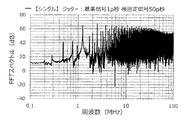
図9に示すアイドルトーン分散装置200(比較例)を用いた。このアイドルトーン分散装置200は、1個のFDSM20を有している。また、アイドルトーン分散装置200は、被測定にジッターを付与するジッター加算器5と、基準信号Fcにジッターを付与するジッター加算器5とを備えている。この装置dを用いる場合、グラフの説明には、「シングル」と記載する。
(Device d)
The idle tone disperser 200 (comparative example) shown in FIG. 9 was used. The
(装置e)
図7に示す第4実施形態のアイドルトーン分散装置1を用いた。また、FDSM20の並列数は、8個とした。また、8個のFDSM20にすべて位相の異なる被測定信号を入力した。また、8個のFDSM20に入力する被測定信号は、1/260M×1/8[秒]ずつ遅延させた。この装置eを用いる場合、グラフの説明には、「等分8並列」および「共通」と記載する。
(Device e)
The idle
<実験1>
装置aを用い、基準信号には、共通のジッターを付与し、被測定信号には、FDSM20毎に独立してジッターを付与した。
また、基準信号に付与するジッターの大きさを「10p秒」とし、被測定信号に付与するジッターの大きさを「10p秒」とした(実施例)。
また、基準信号に付与するジッターおよび被測定信号に付与するジッターは、それぞれ、最大の周波数成分が130MHzで、130MHz以下の周波数成分を含んでいる。
<
Using the device a, a common jitter was applied to the reference signal, and a jitter was independently applied to the measured signal for each FDSM 20.
Further, the magnitude of the jitter applied to the reference signal was set to "10 ps", and the magnitude of the jitter applied to the measured signal was set to "10 ps" (Example).
Further, the jitter applied to the reference signal and the jitter applied to the measured signal each have a maximum frequency component of 130 MHz and include a frequency component of 130 MHz or less.
この場合、測定帯域(計測帯域)の上限値は、130MHz未満に設定する。これにより、装置aから出力される周波数デルタシグマ変調信号のアイドルトーンのうち、対象となるアイドルトーンの周波数は、130MHz未満となる。すなわち、基準信号に付与するジッターおよび被測定信号に付与するジッターは、それぞれ、アイドルトーンの周波数よりも高い周波数成分を含むこととなる。
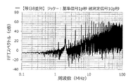
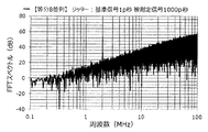
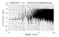
アイドルトーン分散装置から出力される周波数デルタシグマ変調信号について、含まれる周波数成分の強度を求め、アイドルトーン分散装置の出力スペクトルのグラフを作成した。この結果を図12に示す。
In this case, the upper limit of the measurement band (measurement band) is set to less than 130 MHz. As a result, among the idle tones of the frequency delta-sigma modulation signal output from the device a, the frequency of the target idle tone is less than 130 MHz. That is, the jitter applied to the reference signal and the jitter applied to the measured signal each include a frequency component higher than the frequency of the idle tone.
For the frequency delta-sigma modulated signal output from the idle tone disperser, the intensity of the contained frequency component was obtained, and a graph of the output spectrum of the idle tone disperser was created. The result is shown in FIG.
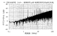
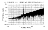
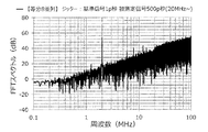
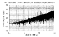
また、他の実施例として、基準信号に付与するジッターの大きさ、被測定信号に付与するジッターの大きさを「20p秒(基準信号)、20p秒(被測定信号)」、「50p秒、50p秒」、「100p秒、100p秒」、「200p秒、200p秒」、「500p秒、500p秒」、「1000p秒、1000p秒」、「2000p秒、2000p秒」とし、アイドルトーン分散装置の出力スペクトルのグラフを作成した。この結果を図13〜図19に示す。 Further, as another embodiment, the magnitude of the jitter applied to the reference signal and the magnitude of the jitter applied to the measured signal are "20 ps (reference signal), 20 ps (measured signal)", "50 ps," "50p seconds", "100p seconds, 100p seconds", "200p seconds, 200p seconds", "500p seconds, 500p seconds", "1000p seconds, 1000p seconds", "2000p seconds, 2000p seconds" A graph of the output spectrum was created. The results are shown in FIGS. 13 to 19.
また、比較例として、装置aにおいて、基準信号および被測定信号にそれぞれジッターが含まれていない場合(ジッターの大きさが0p秒)について、シミュレーションを行って、アイドルトーン分散装置の出力スペクトルのグラフを作成した。この結果を図11に示す。
各グラフの横軸は、高速フーリエ変換(FFT)を行って求めた周波数成分(周波数)であり、縦軸は、強度(FFTスペクトル)である(図20〜図78も同様)。
Further, as a comparative example, in the device a, when the reference signal and the measured signal do not contain jitter (the magnitude of the jitter is 0 ps), a simulation is performed and a graph of the output spectrum of the idle tone dispersion device is performed. It was created. The result is shown in FIG.
The horizontal axis of each graph is the frequency component (frequency) obtained by performing the fast Fourier transform (FFT), and the vertical axis is the intensity (FFT spectrum) (the same applies to FIGS. 20 to 78).
また、グラフにおいて、2MHzの周波数成分が、検出対象の周波数であり、その2MHzのピークは、他の部分、すなわち、2MHz以外のピークおよびベース部分(ベースノイズ)に対して高いほど好ましい。この2MHzのピークと他の部分との差、例えば、2MHzのピークと、測定帯域内の2MHz以外のピークのうちの最大のピークとの差が、SN比に対応している。一方、2MHz以外のピークは、それぞれ、アイドルトーン(ノイズ)となり得るものであるが、測定帯域内の2MHz以外のピークのみがアイドルトーンであり、測定帯域外のピークは、対象としていない。
本実験の結果から、基準信号および被測定信号がジッターを含む場合は、基準信号および被測定信号がジッターを含まない場合に比べて、アイドルトーンの影響が抑制されることが判る。また、ジッターの大きさに応じて、アイドルトーンの影響を抑制する効果(アイドルトーン抑制効果)が異なることも判る。
Further, in the graph, the frequency component of 2 MHz is the frequency to be detected, and the peak of 2 MHz is preferably higher with respect to other portions, that is, peaks other than 2 MHz and the base portion (base noise). The difference between the 2 MHz peak and other parts, for example, the difference between the 2 MHz peak and the maximum peak among the peaks other than 2 MHz in the measurement band corresponds to the SN ratio. On the other hand, peaks other than 2 MHz can be idle tones (noise), respectively, but only peaks other than 2 MHz in the measurement band are idle tones, and peaks outside the measurement band are not targeted.
From the results of this experiment, it can be seen that when the reference signal and the measured signal contain jitter, the influence of the idle tone is suppressed as compared with the case where the reference signal and the measured signal do not contain jitter. It can also be seen that the effect of suppressing the influence of the idle tone (idle tone suppressing effect) differs depending on the magnitude of the jitter.
例えば、基準信号および被測定信号が100p秒のジッターを含む図15に示すグラフと、基準信号および被測定信号がジッターを含まない図11に示すグラフとを比べると、100p秒のジッターを含む場合は、アイドルトーンを示すピークが低くなり、特に周波数が3MHz以下においてアイドルトーンの影響が抑制されることが判る。 For example, comparing the graph shown in FIG. 15 in which the reference signal and the measured signal include jitter of 100 ps and the graph shown in FIG. 11 in which the reference signal and the measured signal do not include jitter, there is a case where the jitter of 100 ps is included. It can be seen that the peak indicating the idle tone becomes low, and the influence of the idle tone is suppressed particularly when the frequency is 3 MHz or less.
また、各実施例のうち、基準信号および被測定信号が10p秒のジッターを含む場合が最も効果が低いものであるが、その10p秒のジッターを含む図12に示すグラフと、基準信号および被測定信号がジッターを含まない図11に示すグラフとを比べても、10p秒のジッターを含む場合は、特に周波数が1MHz以下においてアイドルトーンの影響が抑制されることが判る。 Further, in each embodiment, the case where the reference signal and the measured signal include a jitter of 10 ps is the least effective, but the graph shown in FIG. 12 including the jitter of 10 ps, the reference signal, and the subject are taken. Comparing with the graph shown in FIG. 11 in which the measured signal does not contain jitter, it can be seen that when the measured signal contains jitter of 10 ps, the influence of idle tone is suppressed especially when the frequency is 1 MHz or less.
また、本実験では、例えば、測定帯域の上限値を3MHz程度に設定する場合は、図15および図16に示すように、ジッターの大きさは、100p秒以上、200p秒以下程度が好ましいことが判る。その理由は、ジッターの大きさが100p秒および200p秒の場合は、周波数が3MHz以下において、アイドルトーンを示すピークが低く、かつ、ベース部分の強度も抑えられているためである。また、測定帯域の上限値を10MHzに設定する場合は、図17に示すように、ジッターの大きさは、500p秒程度が好ましいことが判る。その理由は、ジッターの大きさが500p秒の場合は、周波数が10MHz以下において、アイドルトーンを示すピークが低く、かつ、ベース部分の強度も抑えられているためである。 Further, in this experiment, for example, when the upper limit of the measurement band is set to about 3 MHz, it is preferable that the amount of jitter is about 100 ps or more and 200 ps or less, as shown in FIGS. 15 and 16. I understand. The reason is that when the magnitude of the jitter is 100 ps and 200 ps, the peak indicating the idle tone is low and the intensity of the base portion is suppressed at a frequency of 3 MHz or less. Further, when the upper limit of the measurement band is set to 10 MHz, as shown in FIG. 17, it can be seen that the magnitude of the jitter is preferably about 500 ps. The reason is that when the magnitude of the jitter is 500 ps, the peak indicating the idle tone is low and the intensity of the base portion is suppressed at a frequency of 10 MHz or less.
<実験2>
実験1の実施例において、被測定信号に付与するジッターの大きさを「1p秒」に固定し、基準信号に付与するジッターの大きさを「10p秒」、「20p秒」、「50p秒」、「100p秒」、「200p秒」、「500p秒」、「1000p秒」、「2000p秒」(実施例)とし、アイドルトーン分散装置の出力スペクトルのグラフを作成した。この結果を図20〜図27に示す。
<
In the embodiment of
この結果から、基準信号のみのジッターの大きさを調整することでもアイドルトーンは抑制されることが判る。
なお、被測定信号がジッターを含まず(ジッターの大きさが0p秒)、基準信号に付与するジッターの大きさを「10p秒」、「20p秒」、「50p秒」、「100p秒」、「200p秒」、「500p秒」、「1000p秒」、「2000p秒」(実施例)とし、シミュレーションを行って、アイドルトーン分散装置の出力スペクトルのグラフを作成したところ、被測定信号のジッターの大きさが1p秒の場合と、ほぼ同様の結果が得られた。これにより、基準信号のみがジッターを含む場合でもアイドルトーンは抑制されることが判る。
From this result, it can be seen that the idle tone is suppressed by adjusting the magnitude of the jitter of only the reference signal.
The signal to be measured does not include jitter (the magnitude of the jitter is 0 ps), and the magnitude of the jitter applied to the reference signal is "10 ps", "20 ps", "50 ps", "100 ps", When "200p seconds", "500p seconds", "1000p seconds", and "2000p seconds" (example) were set and simulation was performed to create a graph of the output spectrum of the idle tone disperser, the jitter of the signal to be measured was found. Almost the same results were obtained when the size was 1 ps. From this, it can be seen that the idle tone is suppressed even when only the reference signal contains jitter.
<実験3>
実験1の実施例において、基準信号に付与するジッターの大きさを「1p秒」に固定し、被測定信号に付与するジッターの大きさを「10p秒」、「20p秒」、「50p秒」、「100p秒」、「200p秒」、「500p秒」、「1000p秒」、「2000p秒」(実施例)とし、アイドルトーン分散装置の出力スペクトルのグラフを作成した。この結果を図28〜図35に示す。
<
In the embodiment of
この結果から、被測定信号のみのジッターの大きさを調整することでもアイドルトーンは抑制されることが判る。
なお、基準信号がジッターを含まず(ジッターの大きさが0p秒)、被測定信号に付与するジッターの大きさを「10p秒」、「20p秒」、「50p秒」、「100p秒」、「200p秒」、「500p秒」、「1000p秒」、「2000p秒」(実施例)とし、シミュレーションを行って、アイドルトーン分散装置の出力スペクトルのグラフを作成したところ、基準信号のジッターの大きさが1p秒の場合と、ほぼ同様の結果が得られた。これにより、被測定信号のみがジッターを含む場合でもアイドルトーンは抑制されることが判る。
また、実験3の図28〜図35に示すグラフと、実験1の図12〜図19に示すグラフとの対応するグラフ同士を比べると、実験1の実施例の方がベース部分の強度は高いことが判る。同様に、実験2についても実験1の実施例の方がベース部分の強度は高いことが判る。
これは、ジッターの大きさが同じ場合、基準信号と被測定信号とのいずれか一方のみにジッターを付与する場合に比べ、両方にジッターを付与する方が系に投入されるノイズのエネルギーが大きくなることに対応している。
From this result, it can be seen that the idle tone is suppressed by adjusting the magnitude of the jitter of only the measured signal.
The reference signal does not include jitter (the magnitude of the jitter is 0 ps), and the magnitude of the jitter applied to the signal under test is "10 ps", "20 ps", "50 ps", "100 ps", When "200p seconds", "500p seconds", "1000p seconds", and "2000p seconds" (example) were set and simulation was performed to create a graph of the output spectrum of the idle tone disperser, the jitter of the reference signal was large. Almost the same results were obtained when the time was 1 ps. From this, it can be seen that the idle tone is suppressed even when only the measured signal contains jitter.
Further, comparing the graphs shown in FIGS. 28 to 35 of
This is because when the magnitude of the jitter is the same, the energy of the noise input to the system is larger when the jitter is applied to only one of the reference signal and the measured signal than when the jitter is applied to both of them. Corresponds to becoming.
<実験4>
装置bを用い、基準信号には、共通のジッターを付与し、被測定信号には、FDSM20毎に独立してジッターを付与した。
また、基準信号に付与するジッターの大きさを「1p秒」とし、被測定信号に付与するジッターの大きさを「10p秒」とした(実施例)。
<Experiment 4>
Using the device b, a common jitter was applied to the reference signal, and a jitter was independently applied to the measured signal for each FDSM 20.
Further, the magnitude of the jitter applied to the reference signal was set to "1 psec", and the magnitude of the jitter applied to the measured signal was set to "10 psec" (Example).
また、実験1の実施例と同様に、基準信号に付与するジッターおよび被測定信号に付与するジッターは、それぞれ、最大の周波数成分が130MHzで、130MHz以下の周波数成分を含んでいる、すなわち、アイドルトーンの周波数よりも高い周波数成分を含んでいる。
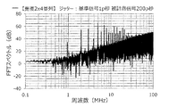
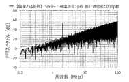
アイドルトーン分散装置から出力される周波数デルタシグマ変調信号について、含まれる周波数成分の強度を求め、アイドルトーン分散装置の出力スペクトルのグラフを作成した。この結果を図37に示す。
Further, as in the embodiment of
For the frequency delta-sigma modulated signal output from the idle tone disperser, the intensity of the contained frequency component was obtained, and a graph of the output spectrum of the idle tone disperser was created. The result is shown in FIG. 37.
また、他の実施例として、基準信号に付与するジッターの大きさを「1p秒」に固定し、被測定信号に付与するジッターの大きさを「20p秒」、「50p秒」、「100p秒」、「200p秒」、「500p秒」、「1000p秒」、「2000p秒」とし、アイドルトーン分散装置の出力スペクトルのグラフを作成した。この結果を図38〜図44に示す。
また、比較例として、装置bにおいて、基準信号および被測定信号にそれぞれジッターが含まれていない場合(ジッターの大きさが0p秒)について、シミュレーションを行って、アイドルトーン分散装置の出力スペクトルのグラフを作成した。この結果を図36に示す。
Further, as another embodiment, the amount of jitter applied to the reference signal is fixed to "1 ps", and the amount of jitter applied to the signal to be measured is "20 ps", "50 ps", "100 ps". , "200p seconds", "500p seconds", "1000p seconds", "2000p seconds", and a graph of the output spectrum of the idle tone disperser was created. The results are shown in FIGS. 38 to 44.
Further, as a comparative example, in the device b, when the reference signal and the measured signal do not contain jitter (the magnitude of the jitter is 0 psec), a simulation is performed and a graph of the output spectrum of the idle tone dispersion device is performed. It was created. The result is shown in FIG.
本実験の結果から、同相の被測定信号が入力されるFDSM20の組がある場合でも、基準信号および被測定信号がジッターを含む場合は、基準信号および被測定信号がジッターを含まない場合に比べて、アイドルトーンの影響が抑制されることが判る。
なお、基準信号がジッターを含まず(ジッターの大きさが0p秒)、被測定信号に付与するジッターの大きさを「10p秒」、「20p秒」、「50p秒」、「100p秒」、「200p秒」、「500p秒」、「1000p秒」、「2000p秒」(実施例)とし、シミュレーションを行って、アイドルトーン分散装置の出力スペクトルのグラフを作成したところ、基準信号のジッターの大きさが1p秒の場合と、ほぼ同様の結果が得られた。これにより、被測定信号のみがジッターを含む場合でもアイドルトーンは抑制されることが判る。
また、測定帯域の上限値を10MHzに設定する場合、実験1の実施例では、前述したように、ジッターの大きさの最適値は、500p秒程度であるが、実験4の実施例では、図43に示すように、ジッターの大きさの最適値は、1000p秒程度であり、実験1の実施例の2倍程度となっている。
From the results of this experiment, even if there is a set of FDSM20 in which in-phase measured signals are input, when the reference signal and the measured signal contain jitter, compared to the case where the reference signal and the measured signal do not contain jitter. It can be seen that the influence of the idle tone is suppressed.
The reference signal does not include jitter (the magnitude of the jitter is 0 ps), and the magnitude of the jitter applied to the signal under test is "10 ps", "20 ps", "50 ps", "100 ps", When "200p seconds", "500p seconds", "1000p seconds", and "2000p seconds" (example) were set and simulation was performed to create a graph of the output spectrum of the idle tone disperser, the jitter of the reference signal was large. Almost the same results were obtained when the time was 1 ps. From this, it can be seen that the idle tone is suppressed even when only the measured signal contains jitter.
Further, when the upper limit of the measurement band is set to 10 MHz, the optimum value of the amount of jitter is about 500 ps in the example of
<実験5>
装置cを用い、基準信号には、共通のジッターを付与し、被測定信号には、FDSM20毎に独立してジッターを付与した。
また、基準信号に付与するジッターの大きさを「1p秒」とし、被測定信号に付与するジッターの大きさを「10p秒」とした(実施例)。
<
Using the device c, a common jitter was applied to the reference signal, and a jitter was independently applied to the measured signal for each FDSM 20.
Further, the magnitude of the jitter applied to the reference signal was set to "1 psec", and the magnitude of the jitter applied to the measured signal was set to "10 psec" (Example).
また、実験1の実施例と同様に、基準信号に付与するジッターおよび被測定信号に付与するジッターは、それぞれ、最大の周波数成分が130MHzで、130MHz以下の周波数成分を含んでいる、すなわち、アイドルトーンの周波数よりも高い周波数成分を含んでいる。
アイドルトーン分散装置から出力される周波数デルタシグマ変調信号について、含まれる周波数成分の強度を求め、アイドルトーン分散装置の出力スペクトルのグラフを作成した。この結果を図46に示す。
Further, as in the embodiment of
For the frequency delta-sigma modulated signal output from the idle tone disperser, the intensity of the contained frequency component was obtained, and a graph of the output spectrum of the idle tone disperser was created. The result is shown in FIG.
また、他の実施例として、基準信号に付与するジッターの大きさを「1p秒」に固定し、被測定信号に付与するジッターの大きさを「20p秒」、「50p秒」、「100p秒」、「200p秒」、「500p秒」、「1000p秒」、「2000p秒」、「3600p秒」とし、アイドルトーン分散装置の出力スペクトルのグラフを作成した。この結果を図47〜図54に示す。
また、比較例として、装置cにおいて、基準信号および被測定信号にそれぞれジッターが含まれていない場合(ジッターの大きさが0p秒)について、シミュレーションを行って、アイドルトーン分散装置の出力スペクトルのグラフを作成した。この結果を図45に示す。
Further, as another embodiment, the amount of jitter applied to the reference signal is fixed to "1 ps", and the amount of jitter applied to the signal to be measured is "20 ps", "50 ps", "100 ps". , "200p seconds", "500p seconds", "1000p seconds", "2000p seconds", "3600p seconds", and a graph of the output spectrum of the idle tone disperser was created. The results are shown in FIGS. 47 to 54.
Further, as a comparative example, in the device c, when the reference signal and the measured signal do not contain jitter (the magnitude of the jitter is 0 ps), a simulation is performed and a graph of the output spectrum of the idle tone dispersion device is performed. It was created. The result is shown in FIG.
本実験の結果から、すべてのFDSM20に同一の位相の被測定信号を入力する場合でも、基準信号および被測定信号がジッターを含む場合は、基準信号および被測定信号がジッターを含まない場合に比べて、アイドルトーンの影響が抑制されることが判る。
なお、基準信号がジッターを含まず(ジッターの大きさが0p秒)、被測定信号に付与するジッターの大きさを「10p秒」、「20p秒」、「50p秒」、「100p秒」、「200p秒」、「500p秒」、「1000p秒」、「2000p秒」、「3600p秒」(実施例)とし、シミュレーションを行って、アイドルトーン分散装置の出力スペクトルのグラフを作成したところ、基準信号のジッターの大きさが1p秒の場合と、ほぼ同様の結果が得られた。これにより、被測定信号のみがジッターを含む場合でもアイドルトーンは抑制されることが判る。
また、本実験では、図53に示すように、ジッターの大きさを「2000p秒」にした場合でも、2MHz未満の周波数のアイドルトーンを示すピーク(強度)が、検出対象の周波数である2MHzのピーク(強度)を上回った。
From the results of this experiment, even when the measured signals of the same phase are input to all FDSM20s, when the reference signal and the measured signal contain jitter, compared to the case where the reference signal and the measured signal do not contain jitter. It can be seen that the influence of the idle tone is suppressed.
The reference signal does not include jitter (the magnitude of the jitter is 0 ps), and the magnitude of the jitter applied to the signal under test is "10 ps", "20 ps", "50 ps", "100 ps", When "200p seconds", "500p seconds", "1000p seconds", "2000p seconds", and "3600p seconds" (example) were used for simulation and a graph of the output spectrum of the idle tone disperser was created, the reference was obtained. Almost the same results were obtained when the magnitude of the signal jitter was 1 ps. From this, it can be seen that the idle tone is suppressed even when only the measured signal contains jitter.
Further, in this experiment, as shown in FIG. 53, even when the magnitude of the jitter is set to "2000 ps", the peak (intensity) indicating the idle tone of the frequency less than 2 MHz is the frequency of 2 MHz to be detected. It exceeded the peak (intensity).
そこで、図54に示すように、ジッターの大きさを「3600p秒」まで増やしたところ、2MHzのピークが、2MHz未満の周波数のアイドルトーンを示すピークを上回った。
なお、被検出信号の周波数は、261.24MHz±0.5MHzであることから、ジッターの大きさの理論限界は、その周波数の逆数である約3820秒である。
Therefore, as shown in FIG. 54, when the magnitude of the jitter was increased to "3600 ps", the peak at 2 MHz exceeded the peak indicating the idle tone at a frequency of less than 2 MHz.
Since the frequency of the detected signal is 261.24 MHz ± 0.5 MHz, the theoretical limit of the magnitude of jitter is about 3820 seconds, which is the reciprocal of the frequency.
<実験6>
装置dを用い、基準信号および被測定信号に、独立してジッターを付与した。
また、基準信号に付与するジッターの大きさを「1p秒」とし、被測定信号に付与するジッターの大きさを「10p秒」とした(比較例)。
また、実験1の実施例と同様に、基準信号に付与するジッターおよび被測定信号に付与するジッターは、それぞれ、最大の周波数成分が130MHzで、130MHz以下の周波数成分を含んでいる、すなわち、アイドルトーンの周波数よりも高い周波数成分を含んでいる。
アイドルトーン分散装置から出力される周波数デルタシグマ変調信号について、含まれる周波数成分の強度を求め、アイドルトーン分散装置の出力スペクトルのグラフを作成した。この結果を図56に示す。
<Experiment 6>
Jitter was independently added to the reference signal and the measured signal using the device d.
Further, the magnitude of the jitter applied to the reference signal was set to "1 psec", and the magnitude of the jitter applied to the measured signal was set to "10 psec" (comparative example).
Further, as in the embodiment of
For the frequency delta-sigma modulated signal output from the idle tone disperser, the intensity of the contained frequency component was obtained, and a graph of the output spectrum of the idle tone disperser was created. The result is shown in FIG.
また、他の比較例として、装置dにおいて、基準信号および被測定信号にそれぞれジッターが含まれていない場合(ジッターの大きさが0p秒)について、シミュレーションを行って、アイドルトーン分散装置の出力スペクトルのグラフを作成した。この結果を図55に示す。
また、他の比較例として、基準信号に付与するジッターの大きさを「1p秒」に固定し、被測定信号に付与するジッターの大きさを「20p秒」、「50p秒」、「100p秒」、「200p秒」、「500p秒」、「1000p秒」、「2000p秒」、「3600p秒」とし、アイドルトーン分散装置の出力スペクトルのグラフを作成した。この結果を図57〜図64に示す。
Further, as another comparative example, in the device d, when the reference signal and the measured signal do not contain jitter (the magnitude of the jitter is 0 ps), a simulation is performed and the output spectrum of the idle tone disperser is performed. I made a graph of. The result is shown in FIG. 55.
Further, as another comparative example, the magnitude of the jitter applied to the reference signal is fixed to "1 psec", and the magnitude of the jitter applied to the measured signal is "20 psec", "50 psec", "100 psec". , "200p seconds", "500p seconds", "1000p seconds", "2000p seconds", "3600p seconds", and a graph of the output spectrum of the idle tone disperser was created. The results are shown in FIGS. 57 to 64.
本実験では、図63に示すように、ジッターの大きさを「2000p秒」にした場合でも、2MHz未満の周波数のアイドルトーンを示すピーク(強度)が、検出対象の周波数である2MHzのピーク(強度)を上回った。
そこで、図64に示すように、ジッターの大きさを「3600p秒」まで増やしたところ、2MHzのピークが、2MHz未満の周波数のアイドルトーンを示すピークを上回った。
また、実験6の図56〜図64に示すグラフと、実験5の図46〜図54に示すグラフとの対応するグラフ同士を比べると、実験6の比較例と実験5の実施例とでは、ジッターの大きさに対応するアイドルトーン抑制効果についてはほぼ同じであるが、実験5の実施例では、ベース部分の強度が低下する効果が得られ、ジッターの大きさが増大するほどその効果は顕著となる。
In this experiment, as shown in FIG. 63, even when the magnitude of the jitter is set to "2000 ps", the peak (intensity) indicating the idle tone of the frequency less than 2 MHz is the peak of 2 MHz which is the frequency to be detected (intensity). Strength) was exceeded.
Therefore, as shown in FIG. 64, when the magnitude of the jitter was increased to "3600 ps", the peak at 2 MHz exceeded the peak indicating the idle tone at a frequency of less than 2 MHz.
Further, when the corresponding graphs of the graphs shown in FIGS. 56 to 64 of Experiment 6 and the graphs shown in FIGS. 46 to 54 of
<実験7>
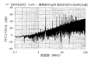
装置eを用い、基準信号に共通のジッターを付与し、また、被測定信号に共通のジッターを付与した。
また、基準信号に付与するジッターの大きさを「1p秒」とし、被測定信号に付与するジッターの大きさを「10p秒」とした(実施例)。
また、実験1の実施例と同様に、基準信号に付与するジッターおよび被測定信号に付与するジッターは、それぞれ、最大の周波数成分が130MHzで、130MHz以下の周波数成分を含んでいる、すなわち、アイドルトーンの周波数よりも高い周波数成分を含んでいる。
<Experiment 7>
The device e was used to impart common jitter to the reference signal and to impart common jitter to the signal under test.
Further, the magnitude of the jitter applied to the reference signal was set to "1 psec", and the magnitude of the jitter applied to the measured signal was set to "10 psec" (Example).
Further, as in the embodiment of
アイドルトーン分散装置から出力される周波数デルタシグマ変調信号について、含まれる周波数成分の強度を求め、アイドルトーン分散装置の出力スペクトルのグラフを作成した。この結果を図65に示す。
また、他の実施例として、基準信号に付与するジッターの大きさを「1p秒」に固定し、被測定信号に付与するジッターの大きさを「20p秒」、「50p秒」、「100p秒」、「200p秒」、「500p秒」、「1000p秒」、「2000p秒」とし、アイドルトーン分散装置の出力スペクトルのグラフを作成した。この結果を図66〜図72に示す。
For the frequency delta-sigma modulated signal output from the idle tone disperser, the intensity of the contained frequency component was obtained, and a graph of the output spectrum of the idle tone disperser was created. The result is shown in FIG.
Further, as another embodiment, the amount of jitter applied to the reference signal is fixed to "1 ps", and the amount of jitter applied to the signal to be measured is "20 ps", "50 ps", "100 ps". , "200p seconds", "500p seconds", "1000p seconds", "2000p seconds", and a graph of the output spectrum of the idle tone disperser was created. The results are shown in FIGS. 66 to 72.
本実験の結果から、基準信号に共通のジッターを付与し、被測定信号に共通のジッターを付与する場合でも、基準信号および被測定信号がジッターを含まない場合に比べて、アイドルトーンの影響が抑制されることが判る。
なお、基準信号がジッターを含まず(ジッターの大きさが0p秒)、被測定信号に付与するジッターの大きさを「10p秒」、「20p秒」、「50p秒」、「100p秒」、「200p秒」、「500p秒」、「1000p秒」、「2000p秒」(実施例)とし、シミュレーションを行って、アイドルトーン分散装置の出力スペクトルのグラフを作成したところ、基準信号のジッターの大きさが1p秒の場合と、ほぼ同様の結果が得られた。これにより、被測定信号のみがジッターを含む場合でもアイドルトーンは抑制されることが判る。
また、実験7の図65〜図72に示すグラフと、実験3の図28〜図35に示すグラフとの対応するグラフ同士を比べると、実験7の実施例と実験3の実施例とでは、実験7の実施例の方がベース部分の強度は高いことが判る。これは、被検出信号に付与されるジッターが独立している場合には、合算したジッターの分布を表す分散はそれぞれの分散の和に近づくのに対し、被検出信号に付与されるジッターが共通である場合には、合算したジッターの分布を表す分散はそれぞれの分散の和よりも大きくなることに対応している。
From the results of this experiment, even when common jitter is applied to the reference signal and common jitter is applied to the measured signal, the effect of idle tone is greater than when the reference signal and the measured signal do not contain jitter. It turns out that it is suppressed.
The reference signal does not include jitter (the magnitude of the jitter is 0 ps), and the magnitude of the jitter applied to the signal under test is "10 ps", "20 ps", "50 ps", "100 ps", When "200p seconds", "500p seconds", "1000p seconds", and "2000p seconds" (example) were set and simulation was performed to create a graph of the output spectrum of the idle tone disperser, the jitter of the reference signal was large. Almost the same results were obtained when the time was 1 ps. From this, it can be seen that the idle tone is suppressed even when only the measured signal contains jitter.
Further, comparing the graphs shown in FIGS. 65 to 72 of Experiment 7 with the corresponding graphs of the graphs shown in FIGS. 28 to 35 of
<実験8>
装置aを用い、基準信号には、共通のジッターを付与し、被測定信号には、FDSM20毎に独立してジッターを付与した。
また、基準信号に付与するジッターの大きさを「1p秒」とし、被測定信号に付与するジッターの大きさを「500p秒」とした(実施例)。
また、実験1の実施例と同様に、基準信号に付与するジッターおよび被測定信号に付与するジッターは、それぞれ、最大の周波数成分が130MHzで、130MHz以下の周波数成分を含んでいる、すなわち、アイドルトーンの周波数よりも高い周波数成分を含んでいる。また、ジッターに含まれる1MHz以下の周波数成分を除去するために、セレクター53において、1MHz以下の変動成分を除去した選択パターンを用いた。
<
Using the device a, a common jitter was applied to the reference signal, and a jitter was independently applied to the measured signal for each FDSM 20.
Further, the magnitude of the jitter applied to the reference signal was set to "1 psec", and the magnitude of the jitter applied to the measured signal was set to "500 psec" (Example).
Further, as in the embodiment of
アイドルトーン分散装置から出力される周波数デルタシグマ変調信号について、含まれる周波数成分の強度を求め、アイドルトーン分散装置の出力スペクトルのグラフを作成した。この結果を図73に示す。 For the frequency delta-sigma modulated signal output from the idle tone disperser, the intensity of the contained frequency component was obtained, and a graph of the output spectrum of the idle tone disperser was created. The result is shown in FIG. 73.
また、他の実施例として、付与するジッターを2MHz以下の低周波数成分を除去したジッター、5MHz以下の低周波数成分を除去したジッター、10MHz以下の低周波数成分を除去したジッター、20MHz以下の低周波数成分を除去したジッター、50MHz以下の低周波数成分を除去したジッター、100MHz以下の低周波数成分を除去したジッターとし、アイドルトーン分散装置の出力スペクトルのグラフを作成した。この結果を図74〜図79に示す。なお、グラフの説明には、それぞれ、「1MHz〜」、「2MHz〜」、「5MHz〜」、「10MHz〜」、「20MHz〜」、「50MHz〜」、「100MHz〜」と記載する。 Further, as another embodiment, the jitter to be applied is a jitter obtained by removing a low frequency component of 2 MHz or less, a jitter obtained by removing a low frequency component of 5 MHz or less, a jitter obtained by removing a low frequency component of 10 MHz or less, and a low frequency of 20 MHz or less. A graph of the output spectrum of the idle tone disperser was created with the jitter from which the component was removed, the jitter from which the low frequency component of 50 MHz or less was removed, and the jitter from which the low frequency component of 100 MHz or less was removed. The results are shown in FIGS. 74 to 79. In the explanation of the graph, "1 MHz to", "2 MHz to", "5 MHz to", "10 MHz to", "20 MHz to", "50 MHz to", and "100 MHz to" are described, respectively.
実験8の図73〜図79に示すグラフと、実験3の図33に示すグラフとを比べると、ジッターの高周波数成分がアイドルトーンの影響を抑制する機能を有することが判る。
また、ジッターに含まれる低周波数成分を除去することで、除去した周波数帯域において、ベース部分の強度が低下することが判る。
Comparing the graphs shown in FIGS. 73 to 79 of
Further, it can be seen that by removing the low frequency component contained in the jitter, the strength of the base portion is lowered in the removed frequency band.
<周波数比計測装置の実施形態>
図80は、本発明の周波数比計測装置の実施形態を示すブロック図である。
以下、周波数比計測装置の実施形態について、前述した実施形態との相違点を中心に説明し、同様の事項については、その説明を省略する。
<Embodiment of frequency ratio measuring device>
FIG. 80 is a block diagram showing an embodiment of the frequency ratio measuring device of the present invention.
Hereinafter, the embodiment of the frequency ratio measuring device will be described mainly on the differences from the above-described embodiment, and the description thereof will be omitted for the same matters.
図80に示すように、周波数比計測装置100は、アイドルトーン分散装置1を備え、被測定信号Fxと基準信号Fcとの周波数比を測定(計測)する。このような周波数比計測装置100によれば、アイドルトーンに起因する量子化雑音の影響を抑制することができ、これにより、測定精度を向上させることができる。以下、具体的に説明する。なお、本実施形態では、周波数比計測装置100として、被測定信号Fxと基準信号Fcとの周波数比を測定した後、被測定信号Fxの周波数を示す周波数データDfを生成する装置を説明する。
周波数比計測装置100は、アイドルトーン分散装置1と、アイドルトーン分散装置1から出力された周波数デルタシグマ変調信号Yに基づいて被測定信号Fxの周波数を示す周波数データDfを生成する周波数データ生成部40とを備えている。また、周波数データ生成部40は、アイドルトーン分散装置1の出力側(後段)に接続されている。また、周波数データ生成部40は、ローパスフィルター41と、ローパスフィルター41の出力側に接続されたスケーリング部42とを備えている。
As shown in FIG. 80, the frequency
The frequency
まず、周波数デルタシグマ変調信号Yが、データストリーム構成のアイドルトーン分散装置1からの出力である場合、周波数デルタシグマ変調信号Yは、被測定信号Fxの周波数fxと基準信号Fcの周波数fcとの比(fx/fc)を、量子化誤差を含んだ形で時間経過と共にデジタル信号列として出力されるものである。
また、周波数デルタシグマ変調信号Yが、ビットストリーム構成のアイドルトーン分散装置1からの出力であって、2fx<fcである場合、周波数デルタシグマ変調信号Yは、被測定信号Fxの2倍の周波数2fxと基準信号Fcの周波数fcとの比(2fx/fc)を、量子化誤差を含んだ形で時間経過と共にデジタル信号列として出力されるものである。
First, when the frequency delta sigma modulation signal Y is the output from the idle tone disperser 1 in the data stream configuration, the frequency delta sigma modulation signal Y is the frequency fx of the measured signal Fx and the frequency fc of the reference signal Fc. The ratio (fx / fc) is output as a digital signal sequence with the passage of time in a form including a quantization error.
Further, when the frequency delta sigma modulation signal Y is the output from the
また、周波数計測(周波数比計測)における時間分解能および周波数分解能は、ローパスフィルター41の特性により定まる。ローパスフィルター41としては、特に限定されず、例えば、直近の複数のサンプルの単純平均を行う移動平均フィルターを複数個配した複数段の移動平均フィルターや、FIRフィルタやIIRフィルタ等で実現される通常のローパスフィルター等を用いることができる。
また、スケーリング部42は、ローパスフィルター41の出力データ41aに補正係数を乗算して周波数データDfを生成する。例えば、周波数データ生成部40の入力側(前段)にビットストリーム構成のアイドルトーン分散装置1が設けられており、例えば、被測定信号Fxの周波数fxが0.1MHz、基準信号Fcの周波数fcが2MHzとすると、2fx/fc=0.1となる。また、周波数デルタシグマ変調信号Yは、被測定信号Fxの周波数fxに比例するので、補正係数は1Mとすればよい。
なお、周波数比計測装置100は、例えば、スケーリング部42が省略され、被測定信号Fxと基準信号Fcとの周波数比を示す周波数比データを生成するようになっていてもよく、また、ローパスフィルター41が省略されていてもよい。
Further, the time resolution and the frequency resolution in the frequency measurement (frequency ratio measurement) are determined by the characteristics of the low-
Further, the scaling
In the frequency
以上、本発明のアイドルトーン分散装置および周波数比計測装置を、図示の実施形態に基づいて説明したが、本発明はこれに限定されるものではなく、各部の構成は、同様の機能を有する任意の構成のものに置換することができる。また、他の任意の構成物が付加されていてもよい。また、本発明は、前記各実施形態のうちの、任意の2以上の構成(特徴)を組み合わせたものであってもよい。 The idle tone dispersion device and the frequency ratio measuring device of the present invention have been described above based on the illustrated embodiment, but the present invention is not limited thereto, and the configuration of each part is arbitrary having the same function. Can be replaced with the one of the configuration of. Further, any other constituent may be added. Further, the present invention may be a combination of any two or more configurations (features) in each of the above embodiments.
また、ジッター加算器(ジッター生成部)を設置する箇所は、前記実施形態には限定されず、例えば、基準信号(出力基準信号)にジッターを付与する場合は、出力基準信号毎に独立に設けられたジッター加算器と、複数の出力基準信号に共通のジッター加算器とが混在していてもよい。また、被測定信号((出力被測定信号))にジッターを付与する場合は、出力被測定信号毎に独立に設けられたジッター加算器と、複数の出力被測定信号に共通のジッター加算器とが混在していてもよい。 Further, the place where the jitter adder (jitter generator) is installed is not limited to the above-described embodiment. For example, when jitter is applied to a reference signal (output reference signal), it is provided independently for each output reference signal. The resulting jitter adder and the jitter adder common to a plurality of output reference signals may coexist. When adding jitter to the measured signal ((output measured signal)), a jitter adder provided independently for each output measured signal and a jitter adder common to a plurality of output measured signals are used. May be mixed.
1…アイドルトーン分散装置、5…ジッター加算器、10…位相調整部、20…周波数デルタシグマ変調部(FDSM)、21…アップカウンター、22…第1ラッチ、23…第2ラッチ、24…減算器、25…排他的論理和回路、30…加算器、40…周波数データ生成部、41…ローパスフィルター、42…スケーリング部、50A…エミッターフォロア回路、51…リプルカウンター、51A…加算器、52…遅延素子、52A…トランジスター、53…セレクター、53A…抵抗、54…マルチプレクサー、55…微分器、100…周波数比計測装置、200…アイドルトーン分散装置、551…排他的論理和回路、552…遅延素子 1 ... Idle tone disperser, 5 ... Jitter adder, 10 ... Phase adjuster, 20 ... Frequency delta sigma modulator (FDSM), 21 ... Up counter, 22 ... 1st latch, 23 ... 2nd latch, 24 ... Subtraction Instrument, 25 ... Exclusive OR circuit, 30 ... Adder, 40 ... Frequency data generator, 41 ... Low pass filter, 42 ... Scaling unit, 50A ... Emitter follower circuit, 51 ... Ripple counter, 51A ... Adder, 52 ... Delay element, 52A ... Transistor, 53 ... Selector, 53A ... Resistance, 54 ... multiplexer, 55 ... Differentiator, 100 ... Frequency ratio measuring device, 200 ... Idle tone disperser, 551 ... Exclusive OR circuit, 552 ... Delay element
Claims (9)
n(nは2以上の任意の自然数)個の周波数デルタシグマ変調部と、
前記n個の周波数デルタシグマ変調部の出力信号を加算して前記周波数デルタシグマ変調信号を出力する加算部と、
前記周波数デルタシグマ変調部の出力信号のアイドルトーンの周波数よりも高い周波数成分を含むジッターを生成するハードウェアと、を備え、
前記n個の周波数デルタシグマ変調部の各々は、前記基準信号と前記被測定信号とのいずれか一方を用いて他方を周波数デルタシグマ変調し、
前記基準信号と前記被測定信号との少なくとも一方は、前記ジッターを有することを特徴とするアイドルトーン分散装置。 It is an idle tone disperser that outputs a frequency delta sigma modulated signal in which one of the reference signal and the measured signal is used and the other is frequency delta sigma modulated to disperse the idle tone.
With n (n is an arbitrary natural number of 2 or more) frequency delta-sigma modulators,
An addition unit that adds the output signals of the n frequency delta sigma modulation units and outputs the frequency delta sigma modulation signal, and a addition unit.
The hardware includes hardware that generates jitter including a frequency component higher than the frequency of the idle tone of the output signal of the frequency delta-sigma modulator.
Each of the n frequency delta sigma modulators uses one of the reference signal and the measured signal to perform frequency delta sigma modulation on the other.
It said reference signal and said at least one of the measured signal, before idle tones dispersion apparatus characterized by having a pheasant Potter.
n(nは2以上の任意の自然数)個の周波数デルタシグマ変調部と、
前記被測定信号と前記基準信号との位相を調整して、n組の出力被測定信号および出力基準信号を生成して、各組の前記出力被測定信号および前記出力基準信号を前記n個の周波数デルタシグマ変調部の各々に供給する位相調整部と、
前記n個の周波数デルタシグマ変調部の出力信号を加算して前記周波数デルタシグマ変調信号を出力する加算部と、
前記周波数デルタシグマ変調部の出力信号のアイドルトーンの周波数よりも高い周波数成分を含むジッターを生成するハードウェアと、を備え、
前記位相調整部は、前記n個の周波数デルタシグマ変調部のうちの少なくとも一部の前記周波数デルタシグマ変調部の出力信号のアイドルトーンの位相が互いに異なるように、前記被測定信号と前記基準信号との位相を調整して、前記n組の出力被測定信号および出力基準信号を生成し、
前記n個の周波数デルタシグマ変調部の各々は、前記位相調整部から供給される前記出力基準信号と前記出力被測定信号とのいずれか一方を用いて他方を周波数デルタシグマ変調し、
前記出力基準信号と前記出力被測定信号とのうちの少なくとも1つは、前記ジッターを有することを特徴とするアイドルトーン分散装置。 It is an idle tone disperser that outputs a frequency delta sigma modulated signal in which one of the reference signal and the measured signal is used and the other is frequency delta sigma modulated to disperse the idle tone.
With n (n is an arbitrary natural number of 2 or more) frequency delta-sigma modulators,
By adjusting the phase of the measured signal and the reference signal, n sets of output measured signals and output reference signals are generated, and each set of the output measured signals and the output reference signals is combined with the n sets of the output measured signals and the output reference signals. A phase adjuster that supplies each of the frequency delta sigma modulators,
An addition unit that adds the output signals of the n frequency delta sigma modulation units and outputs the frequency delta sigma modulation signal, and a addition unit.
The hardware includes hardware that generates jitter including a frequency component higher than the frequency of the idle tone of the output signal of the frequency delta-sigma modulator.
The phase adjusting unit has the measured signal and the reference signal so that the phases of the idle tones of the output signals of at least a part of the n frequency delta sigma modulators are different from each other. By adjusting the phase with and, the n sets of output measured signals and output reference signals are generated.
Each of the n frequency delta sigma modulators uses one of the output reference signal and the output measured signal supplied from the phase adjuster to perform frequency delta sigma modulation of the other.
At least one of said output reference signal and said output signal to be measured, before idle tones dispersion apparatus characterized by having a pheasant Potter.
前記位相調整部は、D/n=Pi+1−Piとなるように、前記被測定信号と前記基準信号との位相を調整して、前記n組の出力被測定信号および出力基準信号を生成する請求項2に記載のアイドルトーン分散装置。 A predetermined time is D, one cycle of the measured signal or one cycle of the reference signal is T, m is an arbitrary natural number of n or less, mD / nT is an integer, mD / nT and m are relatively prime, i (i). when the phase difference between the n-1 following an arbitrary natural number) th output signal to be measured is supplied to a frequency delta-sigma modulation of an output reference signal is a P i,
The phase adjusting unit adjusts the phase of the measured signal and the reference signal so that D / n = Pi + 1 −P i, and generates the n sets of output measured signals and the output reference signal. The idle tone disperser according to claim 2.
D/n≠Pi+1−Piである請求項2に記載のアイドルトーン分散装置。 A predetermined time is D, one cycle of the measured signal or one cycle of the reference signal is T, m is an arbitrary natural number of n or less, mD / nT is an integer, mD / nT and m are relatively prime, i (i). when the phase difference between the n-1 following an arbitrary natural number) th output signal to be measured is supplied to a frequency delta-sigma modulation of an output reference signal is a P i,
The idle tone disperser according to claim 2, wherein D / n ≠ Pi + 1 −P i.
前記被測定信号と前記基準信号との周波数比を測定することを特徴とする周波数比計測装置。 The idle tone disperser according to any one of claims 1 to 8 is provided.
A frequency ratio measuring device for measuring the frequency ratio between the signal to be measured and the reference signal.
Priority Applications (2)
| Application Number | Priority Date | Filing Date | Title |
|---|---|---|---|
| JP2017105463A JP6972660B2 (en) | 2017-05-29 | 2017-05-29 | Idle tone disperser and frequency ratio measuring device |
| US15/987,099 US10355708B2 (en) | 2017-05-29 | 2018-05-23 | Idle tone dispersion device and frequency ratio measuring device |
Applications Claiming Priority (1)
| Application Number | Priority Date | Filing Date | Title |
|---|---|---|---|
| JP2017105463A JP6972660B2 (en) | 2017-05-29 | 2017-05-29 | Idle tone disperser and frequency ratio measuring device |
Publications (2)
| Publication Number | Publication Date |
|---|---|
| JP2018201142A JP2018201142A (en) | 2018-12-20 |
| JP6972660B2 true JP6972660B2 (en) | 2021-11-24 |
Family
ID=64401522
Family Applications (1)
| Application Number | Title | Priority Date | Filing Date |
|---|---|---|---|
| JP2017105463A Active JP6972660B2 (en) | 2017-05-29 | 2017-05-29 | Idle tone disperser and frequency ratio measuring device |
Country Status (2)
| Country | Link |
|---|---|
| US (1) | US10355708B2 (en) |
| JP (1) | JP6972660B2 (en) |
Families Citing this family (3)
| Publication number | Priority date | Publication date | Assignee | Title |
|---|---|---|---|---|
| GB2531532B (en) * | 2014-10-20 | 2020-12-30 | Cambridge Consultants | Radio frequency amplifier |
| JP2021036656A (en) | 2019-08-30 | 2021-03-04 | セイコーエプソン株式会社 | Frequency ratio measuring device |
| US11630161B1 (en) * | 2021-11-08 | 2023-04-18 | Advanced Micro Devices, Inc. | Flexible circuit for droop detection |
Family Cites Families (14)
| Publication number | Priority date | Publication date | Assignee | Title |
|---|---|---|---|---|
| US4458165A (en) | 1983-03-23 | 1984-07-03 | Tektronix, Inc. | Programmable delay circuit |
| JPH06104751A (en) * | 1992-09-17 | 1994-04-15 | Fujitsu Ltd | Deltasigma modulation type a/d converter |
| JP3433655B2 (en) * | 1997-10-14 | 2003-08-04 | ヤマハ株式会社 | Waveform shaping device and ΣΔ type D / A converter |
| JP3625400B2 (en) | 1999-09-22 | 2005-03-02 | 株式会社東芝 | Test circuit for variable delay element |
| DE102005026899B4 (en) * | 2005-06-10 | 2007-02-22 | Infineon Technologies Ag | Compensation circuit for clock jitter compensation |
| US7792232B2 (en) * | 2005-06-30 | 2010-09-07 | Intel Corporation | Method and system for link jitter compensation including a fast data recovery circuit |
| US7295642B2 (en) * | 2005-06-30 | 2007-11-13 | Teradyne, Inc. | Jitter compensation and generation in testing communication devices |
| US8045670B2 (en) * | 2007-06-22 | 2011-10-25 | Texas Instruments Incorporated | Interpolative all-digital phase locked loop |
| JP5158764B2 (en) | 2007-09-27 | 2013-03-06 | 川崎マイクロエレクトロニクス株式会社 | Phase shift method and circuit |
| EP2218174A1 (en) * | 2007-11-16 | 2010-08-18 | ST-Ericsson SA | Jitter compensation |
| JP2012052913A (en) * | 2010-09-01 | 2012-03-15 | Advantest Corp | Test apparatus and signal generating apparatus |
| JP6387676B2 (en) | 2014-05-15 | 2018-09-12 | セイコーエプソン株式会社 | Idle tone dispersion device and frequency measurement device |
| JP6519776B2 (en) * | 2015-02-24 | 2019-05-29 | 横河電機株式会社 | Field device with built-in frequency counter and frequency counter |
| US10175130B2 (en) * | 2015-04-20 | 2019-01-08 | Infineon Technologies Ag | System and method for a MEMS sensor |
-
2017
- 2017-05-29 JP JP2017105463A patent/JP6972660B2/en active Active
-
2018
- 2018-05-23 US US15/987,099 patent/US10355708B2/en active Active
Also Published As
| Publication number | Publication date |
|---|---|
| US10355708B2 (en) | 2019-07-16 |
| JP2018201142A (en) | 2018-12-20 |
| US20180343014A1 (en) | 2018-11-29 |
Similar Documents
| Publication | Publication Date | Title |
|---|---|---|
| KR101108132B1 (en) | Testing apparatus and testing method | |
| US9231613B2 (en) | Idle tone dispersion device and frequency measurement device | |
| JP6972660B2 (en) | Idle tone disperser and frequency ratio measuring device | |
| US20180175840A1 (en) | Delay circuit, count value generation circuit, and physical quantity sensor | |
| KR100865662B1 (en) | Noise-shaped digital frequency synthesis | |
| JP5337157B2 (en) | Test apparatus and test method | |
| CN114070271B (en) | Clock jitter generating device and method based on phase interpolation | |
| US7977996B1 (en) | Pulse generator with precision edge placement | |
| WO2010073458A1 (en) | Timing generator, test device, and test rate control method | |
| US7664166B2 (en) | Pleisiochronous repeater system and components thereof | |
| JP5432352B1 (en) | Pulse pattern generation apparatus and pulse pattern generation method | |
| JP5410454B2 (en) | PULSE PATTERN GENERATION DEVICE, ERROR RATE MEASUREMENT SYSTEM USING THE DEVICE, AND PULSE PATTERN GENERATION METHOD | |
| JP5208211B2 (en) | Test apparatus and test method | |
| JP3081593B2 (en) | Communication signal receiver with sampling frequency control | |
| JP6733237B2 (en) | Frequency delta-sigma modulation signal output device | |
| EP2528230B1 (en) | Signal processing | |
| JP5176545B2 (en) | Signal measuring device | |
| JP6761630B2 (en) | Frequency synthesizer | |
| Calbaza et al. | Jitter model of direct digital synthesis clock generators | |
| JP2008118338A (en) | Device for generating jitters | |
| Kim et al. | Analysis and simulation of jitter for high speed channels in VLSI systems | |
| Liu et al. | An ultra-high timing resolution pulse generator with spur suppression and correction of errors based on real-time computation | |
| KR20240149298A (en) | Clock generation device and clock generation method using the same | |
| JP2757090B2 (en) | Divider / multiplier circuit | |
| Gommé et al. | A high-speed on-chip pseudo-random binary sequence generator for multi-tone phase calibration |
Legal Events
| Date | Code | Title | Description |
|---|---|---|---|
| A621 | Written request for application examination |
Free format text: JAPANESE INTERMEDIATE CODE: A621 Effective date: 20200423 |
|
| A977 | Report on retrieval |
Free format text: JAPANESE INTERMEDIATE CODE: A971007 Effective date: 20210524 |
|
| A131 | Notification of reasons for refusal |
Free format text: JAPANESE INTERMEDIATE CODE: A131 Effective date: 20210727 |
|
| A521 | Request for written amendment filed |
Free format text: JAPANESE INTERMEDIATE CODE: A523 Effective date: 20210916 |
|
| TRDD | Decision of grant or rejection written | ||
| A01 | Written decision to grant a patent or to grant a registration (utility model) |
Free format text: JAPANESE INTERMEDIATE CODE: A01 Effective date: 20211005 |
|
| A61 | First payment of annual fees (during grant procedure) |
Free format text: JAPANESE INTERMEDIATE CODE: A61 Effective date: 20211018 |
|
| R150 | Certificate of patent or registration of utility model |
Ref document number: 6972660 Country of ref document: JP Free format text: JAPANESE INTERMEDIATE CODE: R150 |


