JP6972014B2 - Stable InP QDs with thick shell coating and how to generate them - Google Patents
Stable InP QDs with thick shell coating and how to generate them Download PDFInfo
- Publication number
- JP6972014B2 JP6972014B2 JP2018555728A JP2018555728A JP6972014B2 JP 6972014 B2 JP6972014 B2 JP 6972014B2 JP 2018555728 A JP2018555728 A JP 2018555728A JP 2018555728 A JP2018555728 A JP 2018555728A JP 6972014 B2 JP6972014 B2 JP 6972014B2
- Authority
- JP
- Japan
- Prior art keywords
- shell
- znse
- core
- zns
- zinc
- Prior art date
- Legal status (The legal status is an assumption and is not a legal conclusion. Google has not performed a legal analysis and makes no representation as to the accuracy of the status listed.)
- Active
Links
Images


Classifications
-
- C—CHEMISTRY; METALLURGY
- C09—DYES; PAINTS; POLISHES; NATURAL RESINS; ADHESIVES; COMPOSITIONS NOT OTHERWISE PROVIDED FOR; APPLICATIONS OF MATERIALS NOT OTHERWISE PROVIDED FOR
- C09K—MATERIALS FOR MISCELLANEOUS APPLICATIONS, NOT PROVIDED FOR ELSEWHERE
- C09K11/00—Luminescent materials, e.g. electroluminescent or chemiluminescent
- C09K11/02—Use of particular materials as binders, particle coatings or suspension media therefor
-
- C—CHEMISTRY; METALLURGY
- C09—DYES; PAINTS; POLISHES; NATURAL RESINS; ADHESIVES; COMPOSITIONS NOT OTHERWISE PROVIDED FOR; APPLICATIONS OF MATERIALS NOT OTHERWISE PROVIDED FOR
- C09K—MATERIALS FOR MISCELLANEOUS APPLICATIONS, NOT PROVIDED FOR ELSEWHERE
- C09K11/00—Luminescent materials, e.g. electroluminescent or chemiluminescent
- C09K11/08—Luminescent materials, e.g. electroluminescent or chemiluminescent containing inorganic luminescent materials
- C09K11/56—Luminescent materials, e.g. electroluminescent or chemiluminescent containing inorganic luminescent materials containing sulfur
- C09K11/562—Chalcogenides
- C09K11/565—Chalcogenides with zinc cadmium
-
- C—CHEMISTRY; METALLURGY
- C09—DYES; PAINTS; POLISHES; NATURAL RESINS; ADHESIVES; COMPOSITIONS NOT OTHERWISE PROVIDED FOR; APPLICATIONS OF MATERIALS NOT OTHERWISE PROVIDED FOR
- C09K—MATERIALS FOR MISCELLANEOUS APPLICATIONS, NOT PROVIDED FOR ELSEWHERE
- C09K11/00—Luminescent materials, e.g. electroluminescent or chemiluminescent
- C09K11/08—Luminescent materials, e.g. electroluminescent or chemiluminescent containing inorganic luminescent materials
- C09K11/70—Luminescent materials, e.g. electroluminescent or chemiluminescent containing inorganic luminescent materials containing phosphorus
-
- C—CHEMISTRY; METALLURGY
- C09—DYES; PAINTS; POLISHES; NATURAL RESINS; ADHESIVES; COMPOSITIONS NOT OTHERWISE PROVIDED FOR; APPLICATIONS OF MATERIALS NOT OTHERWISE PROVIDED FOR
- C09K—MATERIALS FOR MISCELLANEOUS APPLICATIONS, NOT PROVIDED FOR ELSEWHERE
- C09K11/00—Luminescent materials, e.g. electroluminescent or chemiluminescent
- C09K11/08—Luminescent materials, e.g. electroluminescent or chemiluminescent containing inorganic luminescent materials
- C09K11/88—Luminescent materials, e.g. electroluminescent or chemiluminescent containing inorganic luminescent materials containing selenium, tellurium or unspecified chalcogen elements
- C09K11/881—Chalcogenides
- C09K11/883—Chalcogenides with zinc or cadmium
-
- B—PERFORMING OPERATIONS; TRANSPORTING
- B82—NANOTECHNOLOGY
- B82Y—SPECIFIC USES OR APPLICATIONS OF NANOSTRUCTURES; MEASUREMENT OR ANALYSIS OF NANOSTRUCTURES; MANUFACTURE OR TREATMENT OF NANOSTRUCTURES
- B82Y20/00—Nanooptics, e.g. quantum optics or photonic crystals
-
- B—PERFORMING OPERATIONS; TRANSPORTING
- B82—NANOTECHNOLOGY
- B82Y—SPECIFIC USES OR APPLICATIONS OF NANOSTRUCTURES; MEASUREMENT OR ANALYSIS OF NANOSTRUCTURES; MANUFACTURE OR TREATMENT OF NANOSTRUCTURES
- B82Y40/00—Manufacture or treatment of nanostructures
-
- Y—GENERAL TAGGING OF NEW TECHNOLOGICAL DEVELOPMENTS; GENERAL TAGGING OF CROSS-SECTIONAL TECHNOLOGIES SPANNING OVER SEVERAL SECTIONS OF THE IPC; TECHNICAL SUBJECTS COVERED BY FORMER USPC CROSS-REFERENCE ART COLLECTIONS [XRACs] AND DIGESTS
- Y10—TECHNICAL SUBJECTS COVERED BY FORMER USPC
- Y10S—TECHNICAL SUBJECTS COVERED BY FORMER USPC CROSS-REFERENCE ART COLLECTIONS [XRACs] AND DIGESTS
- Y10S977/00—Nanotechnology
- Y10S977/70—Nanostructure
- Y10S977/773—Nanoparticle, i.e. structure having three dimensions of 100 nm or less
- Y10S977/774—Exhibiting three-dimensional carrier confinement, e.g. quantum dots
-
- Y—GENERAL TAGGING OF NEW TECHNOLOGICAL DEVELOPMENTS; GENERAL TAGGING OF CROSS-SECTIONAL TECHNOLOGIES SPANNING OVER SEVERAL SECTIONS OF THE IPC; TECHNICAL SUBJECTS COVERED BY FORMER USPC CROSS-REFERENCE ART COLLECTIONS [XRACs] AND DIGESTS
- Y10—TECHNICAL SUBJECTS COVERED BY FORMER USPC
- Y10S—TECHNICAL SUBJECTS COVERED BY FORMER USPC CROSS-REFERENCE ART COLLECTIONS [XRACs] AND DIGESTS
- Y10S977/00—Nanotechnology
- Y10S977/70—Nanostructure
- Y10S977/813—Of specified inorganic semiconductor composition, e.g. periodic table group IV-VI compositions
- Y10S977/815—Group III-V based compounds, e.g. AlaGabIncNxPyAsz
- Y10S977/818—III-P based compounds, e.g. AlxGayIn2P
-
- Y—GENERAL TAGGING OF NEW TECHNOLOGICAL DEVELOPMENTS; GENERAL TAGGING OF CROSS-SECTIONAL TECHNOLOGIES SPANNING OVER SEVERAL SECTIONS OF THE IPC; TECHNICAL SUBJECTS COVERED BY FORMER USPC CROSS-REFERENCE ART COLLECTIONS [XRACs] AND DIGESTS
- Y10—TECHNICAL SUBJECTS COVERED BY FORMER USPC
- Y10S—TECHNICAL SUBJECTS COVERED BY FORMER USPC CROSS-REFERENCE ART COLLECTIONS [XRACs] AND DIGESTS
- Y10S977/00—Nanotechnology
- Y10S977/70—Nanostructure
- Y10S977/813—Of specified inorganic semiconductor composition, e.g. periodic table group IV-VI compositions
- Y10S977/824—Group II-VI nonoxide compounds, e.g. CdxMnyTe
-
- Y—GENERAL TAGGING OF NEW TECHNOLOGICAL DEVELOPMENTS; GENERAL TAGGING OF CROSS-SECTIONAL TECHNOLOGIES SPANNING OVER SEVERAL SECTIONS OF THE IPC; TECHNICAL SUBJECTS COVERED BY FORMER USPC CROSS-REFERENCE ART COLLECTIONS [XRACs] AND DIGESTS
- Y10—TECHNICAL SUBJECTS COVERED BY FORMER USPC
- Y10S—TECHNICAL SUBJECTS COVERED BY FORMER USPC CROSS-REFERENCE ART COLLECTIONS [XRACs] AND DIGESTS
- Y10S977/00—Nanotechnology
- Y10S977/84—Manufacture, treatment, or detection of nanostructure
- Y10S977/89—Deposition of materials, e.g. coating, cvd, or ald
- Y10S977/892—Liquid phase deposition
-
- Y—GENERAL TAGGING OF NEW TECHNOLOGICAL DEVELOPMENTS; GENERAL TAGGING OF CROSS-SECTIONAL TECHNOLOGIES SPANNING OVER SEVERAL SECTIONS OF THE IPC; TECHNICAL SUBJECTS COVERED BY FORMER USPC CROSS-REFERENCE ART COLLECTIONS [XRACs] AND DIGESTS
- Y10—TECHNICAL SUBJECTS COVERED BY FORMER USPC
- Y10S—TECHNICAL SUBJECTS COVERED BY FORMER USPC CROSS-REFERENCE ART COLLECTIONS [XRACs] AND DIGESTS
- Y10S977/00—Nanotechnology
- Y10S977/902—Specified use of nanostructure
- Y10S977/932—Specified use of nanostructure for electronic or optoelectronic application
- Y10S977/949—Radiation emitter using nanostructure
- Y10S977/95—Electromagnetic energy
Landscapes
- Chemical & Material Sciences (AREA)
- Engineering & Computer Science (AREA)
- Materials Engineering (AREA)
- Organic Chemistry (AREA)
- Inorganic Chemistry (AREA)
- Luminescent Compositions (AREA)
- Optical Filters (AREA)
Description
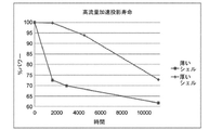
[0001] 高発光性ナノ構造(highly luminescent nanostructure)、特に、ナノ結晶コアとZnSe及びZnSの厚いシェルとを含む、高発光性量子ドットが提供される。ナノ構造は、ZnSe及びZnSのシェルの間に1つ以上の傾斜ZnSexS1−x単層を有し得る。ここで、xの値はナノ構造の内部から外部へ向かって徐々に小さくなる。また、高温合成方法を含むナノ構造を調製する方法も提供される。本発明の厚いシェルのナノ構造は、安定性の増大を示し、長期間にわたって高レベルのフォトルミネッセンス強度を維持することができる。また、青色光吸収が増大したナノ構造も提供される。 [0001] Highly luminescent nanostructures are provided that include highly luminescent nanostructures, in particular a nanocrystal core and a thick shell of ZnSe and ZnS. Nanostructures may have one or more inclined ZnSe x S 1-x monolayers between the ZnSe and ZnS shells. Here, the value of x gradually decreases from the inside to the outside of the nanostructure. Also provided are methods of preparing nanostructures, including high temperature synthesis methods. The nanostructures of the thick shells of the present invention show increased stability and can maintain high levels of photoluminescence intensity over a long period of time. Also provided are nanostructures with increased blue light absorption.
[0002] 半導体ナノ構造は、様々な電子デバイス及び光学デバイスに組み込むことができる。そのようなナノ構造の電気特性及び光学特性は、例えばそれらの組成、形状、及びサイズに応じて変動する。例えば半導体ナノ粒子のサイズ調整可能な特性は、発光ダイオード(LED)、レーザ、及び生物医学的標識等の用途にとって重要である。そのような用途では、高発光性ナノ構造が特に望ましい。 [0002] Semiconductor nanostructures can be incorporated into a variety of electronic and optical devices. The electrical and optical properties of such nanostructures vary, for example, depending on their composition, shape, and size. For example, the size-adjustable properties of semiconductor nanoparticles are important for applications such as light emitting diodes (LEDs), lasers, and biomedical labels. Highly luminescent nanostructures are particularly desirable for such applications.
[0003] LED及びディスプレイ等の用途においてナノ構造の可能性を最大限に活用するため、ナノ構造は5つの基準を同時に満たす必要がある。すなわち、狭く対称的な発光スペクトル、高いフォトルミネッセンス(PL)量子収率(QY:quantum yield)、高い光学安定性、環境に配慮した材料、及び大量生産向けの低コストの方法である。高放射性及び色調整可能な量子ドットに関するほとんどの過去の研究は、カドミウム、水銀、又は鉛を含む材料を中心としている。Wang, A.等のNanoscale 7: 2951-2959(2015)を参照のこと。しかしながら、カドミウム、水銀、又は鉛のような毒性物質が人の健康及び環境に重大な脅威を与える懸念が高まっており、欧州連合の特定有害物質使用制限に関する指令(Restriction of Hazardous Substances rules)は、これらの材料を微量よりも多く含有する家庭用電化製品を禁止している。従って、LED及びディスプレイの製造のために、カドミウム、水銀、及び鉛を含まない材料を生成する必要がある。 [0003] In order to maximize the potential of nanostructures in applications such as LEDs and displays, nanostructures must meet five criteria at the same time. That is, a narrow and symmetric emission spectrum, high photoluminescence (PL) quantum yield (QY), high optical stability, environmentally friendly materials, and a low cost method for mass production. Most past studies on highly radioactive and color-adjustable QDs have focused on materials containing cadmium, mercury, or lead. See Nanoscale 7: 2951-2959 (2015) by Wang, A. et al. However, there is growing concern that toxic substances such as cadmium, mercury, or lead pose a significant threat to human health and the environment, and the European Union's Restriction of Hazardous Substances rules have stated that Household appliances containing more than trace amounts of these materials are banned. Therefore, it is necessary to produce cadmium, mercury, and lead-free materials for the manufacture of LEDs and displays.
[0004] リン化インジウム系のカドミウムフリーの量子ドットは、原型のセレン化カドミウム量子ドットよりも本質的に安定性が低い。価電子帯及び伝導帯の高いエネルギレベルによって、InP量子ドットは、励起された量子ドットから酸素への電子移動による光酸化を生じやすくなり、また、アミン又はチオール等の電子供与物質が励起された量子ドットの正孔状態を再充填し、このため励起子の放射性再結合を抑制する可能性があるので、フォトルミネッセンスクエンチング(photoluminescence quenching)を生じやすくなる。例えば、Chibli, H.等の「Cytotoxicity of InP/ZnS quantum dots related to reactive oxygen species generation」、Nanoscale 3:2552-2559(2011)、Blackburn, J. L.等の「Electron and Hole Transfer from Indium Phosphide Quantum Dots」、J. Phys. Chem. B 109:2625-2631(2005)、及び、Selmarten, D.等の「Quenching of Semiconductor Quantum Dot Photoluminescence by a π-Conjugated Polymer」、J. Phys. Chem. B 109:15927-15933(2005)を参照のこと。 [0004] Indium phosphide-based cadmium-free QDs are inherently less stable than the original cadmium selenide QDs. The high energy levels of the valence and conduction bands made the InP quantum dots more susceptible to photooxidation due to electron transfer from excited quantum dots to oxygen, and also excited electron donors such as amines or thiols. Photoluminescence quenching is more likely to occur because it refills the hole state of the quantum dots, which may suppress the radiorecoupling of excitons. For example, "Cytotoxicity of InP / ZnS quantum dots related to reactive oxygen species generation" by Chibli, H., etc., "Electron and Hole Transfer from Indium Phosphide Quantum Dots" by Nanoscale 3: 2552-2559 (2011), Blackburn, JL, etc. , J. Phys. Chem. B 109: 2625-2631 (2005), and "Quenching of Semiconductor Quantum Dot Photoluminescence by a π-Conjugated Polymer" by Selmarten, D. et al., J. Phys. Chem. B 109: 15927 See -15933 (2005).
[0005] 量子ドットの無機シェルコーティングは、それらの電子構造を調整するための普遍的な手法である。更に、無機シェルの堆積は、表面欠陥の不動態化によっていっそうロバストな粒子を生成することができる。Ziegler, J.等のAdv. Mater. 20:4068-4073(2008)を参照のこと。例えば、ZnS等の広いバンドギャップの半導体材料のシェルを、CdSe又はInP等の狭いバンドギャップのコア上に堆積して、コア内に励起子が閉じ込められた構造を提供することができる。この手法は放射性再結合の確率を高め、1に近い量子収率及び薄いシェルコーティングを有する極めて高効率の量子ドットを合成することを可能とする。 [0005] Quantum dot inorganic shell coatings are a universal technique for adjusting their electronic structure. In addition, the deposition of inorganic shells can produce more robust particles by passivating surface defects. See Adv. Mater. 20: 4068-4073 (2008) by Ziegler, J. et al. For example, a shell of a wide bandgap semiconductor material such as ZnS can be deposited on a narrow bandgap core such as CdSe or InP to provide a structure in which excitons are confined within the core. This technique increases the probability of radioactive recombination and makes it possible to synthesize extremely efficient quantum dots with a quantum yield close to 1 and a thin shell coating.
[0006] 広いバンドギャップの半導体材料のシェルを狭いバンドギャップのコア上に堆積したコアシェル量子ドットは、それでもやはり分解機構(degradation mechanism)を生じる傾向がある。これは、1ナノメートル未満の薄いシェルは環境要因への電荷移動を充分に抑制しないからである。数ナノメートルの厚いシェルコーティングは、トンネリング又は励起子移動の確率を低下させるので、厚いシェルコーティングは安定性を改善すると考えられる。これは、CdSe/CdS系について実証されている所見である。 [0006] Core-shell QDs in which a shell of semiconductor material with a wide bandgap is deposited on a core with a narrow bandgap still tends to produce a degradation mechanism. This is because thin shells less than 1 nanometer do not adequately suppress charge transfer to environmental factors. Thick shell coatings of several nanometers reduce the probability of tunneling or exciton transfer, so thick shell coatings are believed to improve stability. This is a proven finding for the CdSe / CdS system.
[0007] 量子ドットの組成にかかわらず、ほとんどの量子ドットは、励起光子に連続的に暴露された後は最初の高い量子収率を維持しない。多重シェル及び厚いシェルの形成(コア内の搬送波機能は量子ドット表面から遠くなる)等の精巧なシェル形成エンジニアリングは、この光誘起の量子ドット劣化を軽減するのに効果的である。更に、量子ドットの光分解は、それらを酸化物で包むこと、すなわち量子ドット表面を環境から物理的に隔離することで、遅延させ得ることがわかっている。Jo. J.-H.等、J. Alloys Compd. 647:6-13(2015)を参照のこと。 [0007] Regardless of the composition of the quantum dots, most quantum dots do not maintain their initial high quantum yields after continuous exposure to excited photons. Elaborate shell formation engineering, such as the formation of multiple shells and thick shells (carrier function in the core is far from the quantum dot surface), is effective in mitigating this photoinduced quantum dot degradation. Furthermore, it has been found that the photolysis of quantum dots can be delayed by wrapping them in oxide, i.e., physically isolating the quantum dot surface from the environment. See Jo. J.-H. et al., J. Alloys Compd. 647: 6-13 (2015).
[0008] CdSe/CdS巨大シェル量子ドット上の厚いコーティングは、発光コアを表面から数ナノメートル分離させることによって、環境要因及び表面電荷に対する安定性を改善することがわかっている。厚いシェルの量子ドットで見出される安定性の改善を示しながら、薄いシェルの量子ドットの有利な特性も有する、例えば高い量子収率、狭い発光ピーク幅、調整可能な発光波長、及びコロイド安定性を有する材料を生成する必要がある。 [0008] Thick coatings on CdSe / CdS giant shell QDs have been found to improve stability to environmental factors and surface charges by separating the emissive core from the surface by a few nanometers. While demonstrating the stability improvements found in thick-shell QDs, they also have the advantageous properties of thin-shell QDs, such as high quantum yields, narrow emission peak widths, adjustable emission wavelengths, and colloidal stability. It is necessary to produce the material to have.
[0009] 厚いシェルを生成する場合、障害及び分解の多くの可能性があるので、薄いシェルの量子ドットの有利な特性を維持することは難しい。その可能性とは例えば、(1)質量増大、表面対体積率の低減、及び全表面積の増大によるドット沈降(dot precipitation)、(2)ドットを架橋するシェル材料による不可逆凝集、(3)シェル材料の二次核生成、(4)格子ひずみの緩和によって生じる界面欠陥、(5)優先ファセット(preferred facet)上の異方性シェル成長、(6)非晶質シェル又は非エピタキシャル界面、(7)サイズ分布の拡大によって生じる広い発光ピークである。 [0009] When producing thick shells, it is difficult to maintain the favorable properties of quantum dots in thin shells because of the many potential obstacles and decompositions. The possibilities are, for example, (1) increased mass, reduced surface-to-volume ratio, and dot precipitation due to increased total surface area, (2) irreversible aggregation with a shell material that cross-links dots, and (3) shell. Secondary nucleation of the material, (4) interfacial defects caused by relaxation of lattice strain, (5) anisotropic shell growth on the preferred facet, (6) amorphous shell or non-epitaxial interface, (7). ) A wide emission peak caused by the expansion of the size distribution.
[0010] これらの不均質ナノ構造における界面は、欠陥が存在しない状態でなければならない。欠陥は電荷キャリアの捕獲サイトとして作用し、そのため発光効率及び安定性の双方が劣化するからである。これらの半導体材料の格子間隔は本来異なるため、界面における結晶格子はひずむ。このひずみのエネルギ負荷は薄い層の良好なエピタキシャル整合によって補償されるが、厚い層では、シェル材料は緩和してその本来の格子となり、界面において不整合及び欠陥を生じる。シェル材料を増大することと材料の品質を維持することには固有のトレードオフが存在する。従って、これらの問題を克服する適切なシェル組成物を見出す必要がある。 [0010] The interfaces in these inhomogeneous nanostructures must be defect-free. Defects act as charge carrier capture sites, which degrades both luminous efficiency and stability. Since the lattice spacing of these semiconductor materials is originally different, the crystal lattice at the interface is distorted. The energy load of this strain is compensated for by good epitaxial matching of the thin layer, but in the thick layer the shell material relaxes to its original lattice, resulting in inconsistencies and defects at the interface. There are inherent trade-offs between increasing shell material and maintaining material quality. Therefore, it is necessary to find a suitable shell composition that overcomes these problems.
[0011] 最近の進歩によって、高発光性のコアのみのナノ結晶を得ることが可能になっている。しかしながら、これらのコアのみのナノ結晶の合成は安定性及び加工性の問題があり、これらの問題はコアのみのナノ結晶に内在する可能性がある。従って、例えば生物医学的用途のように複雑な化学的処理をナノ結晶に施さなければならない場合、又は、LED及びレーザのようにナノ結晶が一定の励起を必要とする場合は、コア/シェルのナノ結晶が好ましい。Li, J.J.等、J. Am. Chem. Soc. 125:12567-12575(2003)を参照のこと。 [0011] Recent advances have made it possible to obtain highly luminescent core-only nanocrystals. However, the synthesis of these core-only nanocrystals has stability and processability problems, and these problems may be inherent in the core-only nanocrystals. Thus, if complex chemical treatments must be applied to the nanocrystals, for example for biomedical applications, or if the nanocrystals require constant excitation, such as LEDs and lasers, then the core / shell Nanocrystals are preferred. See Li, J.J. et al., J. Am. Chem. Soc. 125: 12567-12575 (2003).
[0012] シェル材料の成長中にサイズ分布を制御するため、考慮しなければならない2つの重要な問題がある。(1)シェル材料の均質な核生成の排除、及び(2)溶液中の全てのコアナノ結晶に対するシェル前駆体の均質な単層成長によって、各コアナノ結晶の周りに等しい厚さのシェル層を生じること、である。連続イオン層吸着及び反応(SILAR:successive ion layer adsorption and reaction)は、元来、溶液槽から固体基板上に薄膜を堆積するために開発されたものであり、化合物半導体の高品質コア/シェルナノ結晶を成長させるための技法として導入されている。 [0012] There are two important issues to consider in order to control the size distribution during the growth of the shell material. (1) Elimination of homogeneous nucleation of shell material and (2) homogeneous monolayer growth of shell precursors for all core nanocrystals in solution results in a shell layer of equal thickness around each core nanocrystal. That is. Successive ion layer adsorption and reaction (SILAR) was originally developed to deposit thin films from solution tanks onto solid substrates and is a high quality core / shell nanocrystal of compound semiconductors. Has been introduced as a technique for growing.
[0013] CdSe/CdSコア/シェルナノ結晶は、SILAR法を用いて、20〜40%のフォトルミネッセンス量子収率で調製されている。Li, J.J.等、J. Am. Chem. Soc. 125:12567-12575(2003)を参照のこと。SILARプロセスでは、各半反応に使用される前駆体の量が、全てのコアのための1つの単層カバレッジと合致するように計算される。これは、反応混合物中に存在する全てのコアの表面積に関する正確な知識を必要とする技法である。また、SILARプロセスは、半反応の双方について定量的な反応収率を仮定しているので、各サイクル後に測定の不正確さが蓄積し、これは制御を失うことにつながる。 [0013] CdSe / CdS core / shell nanocrystals are prepared using the SILAR method with a photoluminescence quantum yield of 20-40%. See Li, J.J. et al., J. Am. Chem. Soc. 125: 12567-12575 (2003). In the SILAR process, the amount of precursor used in each half-reaction is calculated to match one single layer coverage for all cores. This is a technique that requires accurate knowledge of the surface area of all cores present in the reaction mixture. Also, since the SILAR process assumes quantitative reaction yields for both half-reactions, measurement inaccuracies accumulate after each cycle, which leads to loss of control.
[0014] コロイド状原子層堆積(c−ALD:colloidal atomic layer deposition)プロセスは、Ithurria, S.等、J. Am. Chem. Soc. 134:18585-18590(2012)において、コロイド状ナノ構造の合成のために提案された。c−ALDプロセスでは、ナノ粒子又は分子前駆体のいずれかを極性相又は非極性相との間で順次移動させて、未反応前駆体及び副産物が反応混合物中に蓄積するのを防止する。c−ALDプロセスは、コロイド状CdSeナノ結晶、CdSeナノプレートレット、及びCdSナノロッド上にCdS層を成長させるために使用されている。しかしながら、c−ALDプロセスは、ホルムアミド、N−メチル−ホルムアミド、又はヒドラジン等の潜在的に有害な高極性溶媒に対する暴露を伴う相間移動プロトコルを使用する必要がある。 [0014] The colloidal atomic layer deposition (c-ALD) process was performed in Ithurria, S. et al., J. Am. Chem. Soc. 134: 18585-18590 (2012). Proposed for synthesis. In the c-ALD process, either nanoparticles or molecular precursors are sequentially moved between polar and non-polar phases to prevent unreacted precursors and by-products from accumulating in the reaction mixture. The c-ALD process has been used to grow CdS layers on colloidal CdSe nanocrystals, CdSe nanoplatelets, and CdS nanorods. However, the c-ALD process requires the use of a phase transfer protocol with exposure to potentially harmful highly polar solvents such as formamide, N-methyl-formamide, or hydrazine.
[0015] 厚いシェルにおける障害及び分解の可能性を回避する厚いシェルの合成方法を見出す必要がある。本発明は、カドミウムフリーの量子ドットの生成に適用できる厚いシェルのコーティング方法を提供する。 [0015] It is necessary to find a method for synthesizing thick shells that avoids the possibility of failure and decomposition in thick shells. The present invention provides a thick shell coating method applicable to the generation of cadmium-free quantum dots.
[0016] 本発明は、コアと少なくとも2つのシェルとを備えた多層ナノ構造を提供する。シェルのうち少なくとも2つは異なるシェル材料を含み、シェルのうち少なくとも1つの厚さは0.7nmから3.5nmである。 [0016] The present invention provides multi-layered nanostructures with a core and at least two shells. At least two of the shells contain different shell materials and at least one of the shells has a thickness of 0.7 nm to 3.5 nm.
[0017] いくつかの実施形態において、多層ナノ構造のコアはInPを含む。いくつかの実施形態において、多層ナノ構造の少なくとも1つのシェルはZnSを含む。いくつかの実施形態において、多層ナノ構造の少なくとも1つのシェルはZnSeを含む。 [0017] In some embodiments, the core of the multi-layered nanostructure comprises InP. In some embodiments, the at least one shell of the multilayer nanostructure comprises ZnS. In some embodiments, the at least one shell of the multilayer nanostructure comprises ZnSe.
[0018] いくつかの実施形態において、多層ナノ構造のシェルのうち少なくとも1つの厚さは0.9nmから3.5nmである。いくつかの実施形態に置いて、多層ナノ構造のシェルのうち少なくとも2つの厚さは0.7nmから3.5nmである。 [0018] In some embodiments, the thickness of at least one of the multi-layered nanostructured shells is 0.9 nm to 3.5 nm. In some embodiments, at least two of the multi-layered nanostructured shells have a thickness of 0.7 nm to 3.5 nm.
[0019] いくつかの実施形態において、多層ナノ構造のシェルのうち少なくとも1つはZnSを含み、シェルのうち少なくとも1つはZnSeを含み、シェルのうち少なくとも2つの厚さは0.7nmから3.5nmである。 [0019] In some embodiments, at least one of the multi-layered nanostructured shells contains ZnS, at least one of the shells contains ZnSe, and at least two of the shells have a thickness of 0.7 nm to 3 It is 5.5 nm.
[0020] 本発明は、多層ナノ構造を生成する方法を提供する。この方法は、少なくとも1つのシェルを含むナノ構造を提供するため、
(a)ナノ結晶コアを少なくとも2つのシェル前駆体に接触させることと、
(b)約200℃から約310℃の温度で(a)を加熱することと、
を含み、少なくとも1つのシェルは2.5から10の単層を含む。
[0020] The present invention provides a method for producing multi-layer nanostructures. Because this method provides nanostructures containing at least one shell,
(A) Contacting the nanocrystal core with at least two shell precursors and
(B) Heating (a) at a temperature of about 200 ° C to about 310 ° C, and
At least one shell contains 2.5 to 10 single layers.
[0021] いくつかの実施形態において、接触させるナノ結晶コアはInPを含む。 [0021] In some embodiments, the nanocrystal core to be contacted comprises InP.
[0022] いくつかの実施形態において、ナノ結晶コアに接触させる少なくとも2つのシェル前駆体は亜鉛源を含む。いくつかの実施形態において、亜鉛源は、オレイン酸亜鉛、ヘキサン酸亜鉛、オクタン酸亜鉛、ラウリン酸亜鉛、パルミチン酸亜鉛、ステアリン酸亜鉛、ジチオカルバミン酸亜鉛、又はそれらの混合物から成る群から選択される。いくつかの実施形態において、亜鉛源はステアリン酸亜鉛又はオレイン酸亜鉛である。 [0022] In some embodiments, the at least two shell precursors contacted with the nanocrystal core contain a zinc source. In some embodiments, the zinc source is selected from the group consisting of zinc oleate, zinc hexanoate, zinc octanate, zinc laurate, zinc palmitate, zinc stearate, zinc dithiocarbamate, or mixtures thereof. .. In some embodiments, the zinc source is zinc stearate or zinc oleate.
[0023] いくつかの実施形態において、ナノ結晶コアに接触させる少なくとも2つのシェル前駆体はセレン源を含む。いくつかの実施形態において、セレン源は、トリオクチルホスフィンセレニド、トリ(n−ブチル)ホスフィンセレニド、トリ(sec−ブチル)ホスフィンセレニド、トリ(tert−ブチル)ホスフィンセレニド、トリメチルホスフィンセレニド、トリフェニルホスフィンセレニド、ジフェニルホスフィンセレニド、フェニルホスフィンセレニド、トリシクロヘキシルホスフィンセレニド、シクロヘキシルホスフィンセレニド、1−オクタンセレノール(octaneselenol)、1−ドデカンセレノール(dodecaneselenol)、セレノフェノール(selenophenol)、元素セレン、ビス(トリメチルシリル)セレニド、及びそれらの混合物から成る群から選択される。いくつかの実施形態において、セレン源はトリ(n−ブチル)ホスフィンセレニド又はトリオクチルホスフィンセレニドである。 [0023] In some embodiments, the at least two shell precursors contacted with the nanocrystal core contain a selenium source. In some embodiments, the selenium source is trioctylphosphine serenide, tri (n-butyl) phosphine serenide, tri (sec-butyl) phosphine serenide, tri (tert-butyl) phosphine serenide, trimethylphosphine serenide. Nide, Triphenylphosphine Serenide, Diphenylphosphine Serenide, Phenylphosphine Serenide, Tricyclohexylphosphine Serenide, Cyclohexylphosphine Serenide, 1-octaneselenol, 1-dodecaneselenol, Serenophenol ( It is selected from the group consisting of selenophenol), elemental selenium, bis (trimethylsilyl) selenide, and mixtures thereof. In some embodiments, the selenium source is tri (n-butyl) phosphine serenide or trioctylphosphine serenide.
[0024] いくつかの実施形態において、コアとセレン源とのモル比は1:2から1:1000である。いくつかの実施形態において、コアとセレン源とのモル比は1:10から1:1000である。 [0024] In some embodiments, the molar ratio of core to selenium source is 1: 2 to 1: 1000. In some embodiments, the molar ratio of core to selenium source is 1:10 to 1: 1000.
[0025] いくつかの実施形態において、ナノ結晶コアに接触させる少なくとも2つのシェル前駆体は硫黄源を含む。いくつかの実施形態において、硫黄源は、元素硫黄、オクタンチオール、ドデカンチオール、オクタデカンチオール、トリブチルホスフィンスルフィド、イソチオシアン酸シクロヘキシル、α−トルエンチオール、エチレントリチオカルボナート、アリルメルカプタン、ビス(トリメチルシリル)スルフィド、トリオクチルホスフィンスルフィド、及びそれらの混合物から成る群から選択される。いくつかの実施形態において、硫黄源はオクタンチオールである。 [0025] In some embodiments, the at least two shell precursors contacted with the nanocrystal core contain a sulfur source. In some embodiments, the sulfur source is elemental sulfur, octanethiol, dodecanethiol, octadecanethiol, tributylphosphine sulfide, cyclohexyl isothiocyanate, α-toluenethiol, ethylenetrithiocarbonate, allyl mercaptan, bis (trimethylsilyl) sulfide. , Trioctylphosphine sulfide, and mixtures thereof. In some embodiments, the sulfur source is octanethiol.
[0026] いくつかの実施形態において、コアと硫黄源とのモル比は1:2から1:1000である。いくつかの実施形態において、コアと硫黄源とのモル比は1:10から1:1000である。 [0026] In some embodiments, the molar ratio of core to sulfur source is 1: 2 to 1: 1000. In some embodiments, the molar ratio of core to sulfur source is 1:10 to 1: 1000.
[0027] いくつかの実施形態において、ナノ結晶コア及び少なくとも1つのシェル材料は約250℃から約310℃の温度で加熱される。いくつかの実施形態において、ナノ結晶コア及び少なくとも1つのシェル材料は約280℃の温度で加熱される。 [0027] In some embodiments, the nanocrystal core and at least one shell material are heated at a temperature of about 250 ° C to about 310 ° C. In some embodiments, the nanocrystal core and at least one shell material are heated at a temperature of about 280 ° C.
[0028] いくつかの実施形態において、ナノ結晶コア及び少なくとも1つのシェル材料の加熱は2分から240分の間維持される。いくつかの実施形態において、ナノ結晶コア及び少なくとも2つのシェル前駆体の加熱は30分から120分の間維持される。 [0028] In some embodiments, heating of the nanocrystal core and at least one shell material is maintained for 2 to 240 minutes. In some embodiments, heating of the nanocrystal core and at least two shell precursors is maintained for 30 to 120 minutes.
[0029] いくつかの実施形態において、ナノ結晶コアを少なくとも2つのシェル前駆物質に接触させることは溶媒を更に含む。いくつかの実施形態において、溶媒は、1−オクタデセン、1−ヘキサデセン、1−エイコセン、エイコサン、オクタデカン、ヘキサデカン、テトラデカン、スクアレン、スクアラン、トリオクチルホスフィンオキシド、及びジオクチルエーテルから成る群から選択される。いくつかの実施形態において、溶媒は1−オクタデセンである。 [0029] In some embodiments, contacting the nanocrystal core with at least two shell precursors further comprises a solvent. In some embodiments, the solvent is selected from the group consisting of 1-octadecane, 1-hexadecane, 1-eicosene, icosane, octadecane, hexadecane, tetradecane, squalene, squalene, trioctylphosphine oxides, and dioctyl ethers. In some embodiments, the solvent is 1-octadecene.
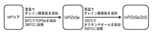
[0030] いくつかの実施形態において、ナノ結晶コアはInPナノ結晶であり、少なくとも1つのシェルはZnSを含み、少なくとも1つのシェルはZnSeを含み、ナノ結晶コア及び少なくとも2つのシェル前駆体の加熱は約250℃から約310℃の温度で行われる。 [0030] In some embodiments, the nanocrystal core is an InP nanocrystal, at least one shell contains ZnS, at least one shell contains ZnSe, and heating of the nanocrystal core and at least two shell precursors. Is carried out at a temperature of about 250 ° C to about 310 ° C.
[0031] 本発明は、多層ナノ構造を生成する方法を提供する。この方法は、少なくとも2つのシェルを含むナノ構造を提供するため、
(a)ナノ結晶コアを少なくとも2つのシェル前駆体に接触させることと、
(b)約200℃から約310℃の温度で(a)を加熱することと、
(c)(b)を少なくとも1つのシェル前駆体に接触させることであって、少なくとも1つのシェル前駆体は(a)におけるシェル前駆体とは異なる、ことと、
(d)約200℃から約310℃の温度で(c)を加熱することと、
を含み、少なくとも1つのシェルは2.5から10の単層を含む。
The present invention provides a method for producing multi-layer nanostructures. Because this method provides nanostructures containing at least two shells,
(A) Contacting the nanocrystal core with at least two shell precursors and
(B) Heating (a) at a temperature of about 200 ° C to about 310 ° C, and
(C) By contacting (b) with at least one shell precursor, at least one shell precursor is different from the shell precursor in (a).
(D) Heating (c) at a temperature of about 200 ° C to about 310 ° C, and
At least one shell contains 2.5 to 10 single layers.
[0032] いくつかの実施形態において、接触させる少なくとも2つのシェル前駆体は亜鉛源を含む。いくつかの実施形態において、亜鉛源は、オレイン酸亜鉛、ヘキサン酸亜鉛、オクタン酸亜鉛、ラウリン酸亜鉛、パルミチン酸亜鉛、ステアリン酸亜鉛、ジチオカルバミン酸亜鉛、又はそれらの混合物から成る群から選択される。いくつかの実施形態において、亜鉛源はステアリン酸亜鉛又はオレイン酸亜鉛である。 [0032] In some embodiments, the contacting at least two shell precursors comprises a zinc source. In some embodiments, the zinc source is selected from the group consisting of zinc oleate, zinc hexanoate, zinc octanate, zinc laurate, zinc palmitate, zinc stearate, zinc dithiocarbamate, or mixtures thereof. .. In some embodiments, the zinc source is zinc stearate or zinc oleate.
[0033] いくつかの実施形態において、接触させる少なくとも2つのシェル前駆体はセレン源を含む。いくつかの実施形態において、セレン源は、トリオクチルホスフィンセレニド、トリ(n−ブチル)ホスフィンセレニド、トリ(sec−ブチル)ホスフィンセレニド、トリ(tert−ブチル)ホスフィンセレニド、トリメチルホスフィンセレニド、トリフェニルホスフィンセレニド、ジフェニルホスフィンセレニド、フェニルホスフィンセレニド、トリシクロヘキシルホスフィンセレニド、シクロヘキシルホスフィンセレニド、1−オクタンセレノール、1−ドデカンセレノール、セレノフェノール、元素セレン、ビス(トリメチルシリル)セレニド、及びそれらの混合物から成る群から選択される。いくつかの実施形態において、セレン源はトリ(n−ブチル)ホスフィンセレニド又はトリオクチルホスフィンセレニドである。 [0033] In some embodiments, the at least two shell precursors to be contacted comprise a selenium source. In some embodiments, the selenium source is trioctylphosphine serenide, tri (n-butyl) phosphine serenide, tri (sec-butyl) phosphine serenide, tri (tert-butyl) phosphine serenide, trimethylphosphine serenide. Nide, Triphenylphosphine Serenide, Diphenylphosphine Serenide, Phenylphosphine Serenide, Tricyclohexylphosphine Serenide, Cyclohexylphosphine Serenide, 1-octane Serenol, 1-Dodecane Serenol, Serenophenol, Element Serene, Bis (trimethylsilyl) ) Select from the group consisting of serenides and mixtures thereof. In some embodiments, the selenium source is tri (n-butyl) phosphine serenide or trioctylphosphine serenide.
[0034] いくつかの実施形態において、接触させる少なくとも2つのシェル前駆体は硫黄源を含む。いくつかの実施形態において、硫黄源は、元素硫黄、オクタンチオール、ドデカンチオール、オクタデカンチオール、トリブチルホスフィンスルフィド、イソチオシアン酸シクロヘキシル、α−トルエンチオール、エチレントリチオカルボナート、アリルメルカプタン、ビス(トリメチルシリル)スルフィド、トリオクチルホスフィンスルフィド、及びそれらの混合物から成る群から選択される。いくつかの実施形態において、硫黄源はオクタンチオールである。 [0034] In some embodiments, the contacting at least two shell precursors comprises a sulfur source. In some embodiments, the sulfur source is elemental sulfur, octanethiol, dodecanethiol, octadecanethiol, tributylphosphine sulfide, cyclohexyl isothiocyanate, α-toluenethiol, ethylenetrithiocarbonate, allyl mercaptan, bis (trimethylsilyl) sulfide. , Trioctylphosphine sulfide, and mixtures thereof. In some embodiments, the sulfur source is octanethiol.
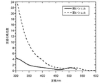
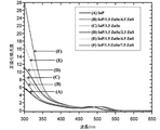
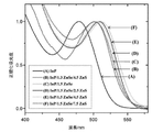
[0035] また、本発明は、コアと少なくとも2つのシェルとを備えた多層ナノ構造を提供する。シェルのうち少なくとも2つは異なるシェル材料を含み、シェルのうち少なくとも1つはシェル材料の約2から約10の単層を含み、ナノ構造は約1.0から約8.0の正規化光学密度を有する。 The present invention also provides multi-layered nanostructures with a core and at least two shells. At least two of the shells contain different shell materials, at least one of the shells contains about 2 to about 10 single layers of shell material, and the nanostructures are about 1.0 to about 8.0 normalized optics. Has a density.
[0036] いくつかの実施形態において、多層ナノ構造は、ZnO、ZnSe、ZnS、ZnTe、CdO、CdSe、CdS、CdTe、HgO、HgS、HgTe、BN、BP、BAs、BSb、AlN、AlP、AlAs、AlSb、GaN、GaP、GaSb、InN、InP、InAs、及びInSbから成る群から選択されるコアを含む。いくつかの実施形態において、多層ナノ構造は、ZnS、ZnSe、CdSe、CdS、及びInPから成る群から選択されるコアを含む。いくつかの実施形態において、多層ナノ構造のコアはInPを含む。 [0036] In some embodiments, the multilayer nanostructures are ZnO, ZnSe, ZnS, ZnTe, CdO, CdSe, CdS, CdTe, HgO, HgS, HgTe, BN, BP, BAs, BSb, AlN, AlP, AlAs. , AlSb, GaN, GaP, GaSb, InN, InP, InAs, and InSb. In some embodiments, the multi-layer nanostructure comprises a core selected from the group consisting of ZnS, ZnSe, CdSe, CdS, and InP. In some embodiments, the core of the multi-layered nanostructure comprises InP.
[0037] いくつかの実施形態において、多層ナノ構造は少なくとも2つのシェルを含み、少なくとも1つのシェルはZnSを含む。 [0037] In some embodiments, the multilayer nanostructure comprises at least two shells and at least one shell comprises ZnS.
[0038] いくつかの実施形態において、多層ナノ構造は少なくとも2つのシェルを含み、少なくとも1つのシェルはZnSeを含む。 [0038] In some embodiments, the multilayer nanostructure comprises at least two shells and at least one shell comprises ZnSe.
[0039] いくつかの実施形態において、多層ナノ構造は少なくとも2つのシェルを含み、シェルのうち少なくとも1つはシェル材料の約3から約8の単層を含む。いくつかの実施形態において、多層ナノ構造は少なくとも2つのシェルを含み、シェルのうち少なくとも1つはシェル材料の約3から約5の単層を含む。 [0039] In some embodiments, the multi-layer nanostructure comprises at least two shells, at least one of which comprises from about 3 to about 8 monolayers of shell material. In some embodiments, the multi-layer nanostructure comprises at least two shells, at least one of which comprises from about 3 to about 5 single layers of shell material.
[0040] いくつかの実施形態において、多層ナノ構造は約1.5から約8.0の正規化光学密度を有する。いくつかの実施形態において、多層ナノ構造は約1.8から約8.0の正規化光学密度を有する。 [0040] In some embodiments, the multilayer nanostructures have a normalized optical density of about 1.5 to about 8.0. In some embodiments, the multilayer nanostructures have a normalized optical density of about 1.8 to about 8.0.
[0041] いくつかの実施形態において、多層ナノ構造は少なくとも2つのシェルを含み、シェルのうち少なくとも1つはZnSeを含み、シェルのうち少なくとも1つはシェル材料の約3から約5の単層を含み、ナノ構造は約1.3から約8.0の正規化光学密度を有する。 [0041] In some embodiments, the multilayer nanostructure comprises at least two shells, at least one of the shells comprises ZnSe, and at least one of the shells is a single layer of about 3 to about 5 shell materials. The nanostructure has a normalized optical density of about 1.3 to about 8.0.
[0042] また、本発明は、コアと少なくとも2つのシェルとを備えた多層ナノ構造を提供する。シェルのうち少なくとも2つは異なるシェル材料を含み、シェルのうち少なくとも1つはシェル材料の約2から約10の単層を含み、シェルのうち少なくとも1つは合金を含み、ナノ構造は約1.0から約8.0の正規化光学密度を有する。 [0042] The present invention also provides multi-layered nanostructures with a core and at least two shells. At least two of the shells contain different shell materials, at least one of the shells contains about 2 to about 10 single layers of shell material, at least one of the shells contains an alloy, and the nanostructure is about 1. It has a normalized optical density of 0.0 to about 8.0.
[0043] いくつかの実施形態において、多層ナノ構造コアは、ZnO、ZnSe、ZnS、ZnTe、CdO、CdSe、CdS、CdTe、HgO、HgS、HgTe、BN、BP、BAs、BSb、AlN、AlP、AlAs、AlSb、GaN、GaP、GaSb、InN、InP、InAs、及びInSbから成る群から選択される。いくつかの実施形態において、多層ナノ構造コアは、ZnS、ZnSe、CdSe、CdS、及びInPから成る群から選択される。いくつかの実施形態において、多層ナノ構造コアはInPを含む。 [0043] In some embodiments, the multilayer nanostructured cores are ZnO, ZnSe, ZnS, ZnTe, CdO, CdSe, CdS, CdTe, HgO, HgS, HgTe, BN, BP, BAs, BSb, AlN, AlP, It is selected from the group consisting of AlAs, AlSb, GaN, GaP, GaSb, InN, InP, InAs, and InSb. In some embodiments, the multilayer nanostructured core is selected from the group consisting of ZnS, ZnSe, CdSe, CdS, and InP. In some embodiments, the multi-layer nanostructured core comprises InP.
[0044] いくつかの実施形態において、多層ナノ構造は少なくとも2つのシェルを含み、少なくとも1つのシェルはZnSを含む。 [0044] In some embodiments, the multilayer nanostructure comprises at least two shells and at least one shell comprises ZnS.
[0045] いくつかの実施形態において、多層ナノ構造は少なくとも2つのシェルを含み、少なくとも1つのシェルはZnSeを含む。 [0045] In some embodiments, the multilayer nanostructure comprises at least two shells and at least one shell comprises ZnSe.
[0046] いくつかの実施形態において、多層ナノ構造は少なくとも2つのシェルを含み、シェルのうち少なくとも1つはシェル材料の約3から約8の単層を含む。いくつかの実施形態において、多層ナノ構造は少なくとも2つのシェルを含み、シェルのうち少なくとも1つはシェル材料の約3から約5の単層を含む。 [0046] In some embodiments, the multilayer nanostructure comprises at least two shells, at least one of which comprises from about 3 to about 8 monolayers of shell material. In some embodiments, the multi-layer nanostructure comprises at least two shells, at least one of which comprises from about 3 to about 5 single layers of shell material.
[0047] いくつかの実施形態において、多層ナノ構造は少なくとも2つのシェルを含み、シェルのうち少なくとも1つは、ZnS、GaN、ZnSe、AlP、CdS、GaP、ZnTe、AlAs、CdSe、AlSb、CdTe、GaAs、Sn、Ge、又はInPを含む合金を含む。いくつかの実施形態において、多層ナノ構造は少なくとも2つのシェルを含み、シェルのうち少なくとも1つはZnTeを含む合金を含む。 [0047] In some embodiments, the multilayer nanostructure comprises at least two shells, one of which is ZnS, GaN, ZnSe, AlP, CdS, GaP, ZnTe, AlAs, CdSe, AlSb, CdTe. , GaAs, Sn, Ge, or alloys containing InP. In some embodiments, the multilayer nanostructure comprises at least two shells, one of which comprises an alloy containing ZnTe.
[0048] いくつかの実施形態において、多層ナノ構造は約1.5から約8.0の正規化光学密度を有する。いくつかの実施形態において、多層ナノ構造は約1.8から約8.0の正規化光学密度を有する。 [0048] In some embodiments, the multilayer nanostructures have a normalized optical density of about 1.5 to about 8.0. In some embodiments, the multilayer nanostructures have a normalized optical density of about 1.8 to about 8.0.
[0049] いくつかの実施形態において、多層ナノ構造は少なくとも2つのシェルを含み、シェルのうち少なくとも1つはZnSeを含み、シェルのうち少なくとも1つはシェル材料の約3から約5の単層を含み、シェルのうち少なくとも1つはZnTeの合金を含み、ナノ構造は約1.8から約8.0の正規化光学密度を有する。 [0049] In some embodiments, the multilayer nanostructure comprises at least two shells, at least one of the shells comprises ZnSe, and at least one of the shells is a single layer of about 3 to about 5 shell materials. And at least one of the shells contains an alloy of ZnTe and the nanostructures have a normalized optical density of about 1.8 to about 8.0.
[0050] いくつかの実施形態において、多層ナノ構造を生成する方法は、約1.0から約8.0の正規化光学密度を有するナノ構造を提供する。 [0050] In some embodiments, the method of producing multi-layered nanostructures provides nanostructures with a normalized optical density of about 1.0 to about 8.0.
[0051] いくつかの実施形態において、多層ナノ構造を生成する方法は、少なくとも1つのシェルを含むナノ構造を提供し、少なくとも1つのシェルは約3から約10の単層を含む。いくつかの実施形態において、多層ナノ構造を生成する方法は、少なくとも1つのシェルを含むナノ構造を提供し、少なくとも1つのシェルは約3から約8の単層を含む。いくつかの実施形態において、多層ナノ構造を生成する方法は、少なくとも1つのシェルを含むナノ構造を提供し、少なくとも1つのシェルは約3から約5の単層を含む。 [0051] In some embodiments, the method of producing multi-layered nanostructures provides nanostructures containing at least one shell, at least one shell comprising from about 3 to about 10 single layers. In some embodiments, the method of producing multi-layered nanostructures provides nanostructures containing at least one shell, the at least one shell comprising from about 3 to about 8 single layers. In some embodiments, the method of producing multi-layered nanostructures provides nanostructures containing at least one shell, the at least one shell comprising from about 3 to about 5 single layers.
[0052] いくつかの実施形態において、多層ナノ構造を生成する方法は、約1.5から約8.0の正規化光学密度を有するナノ構造を提供する。いくつかの実施形態において、多層ナノ構造を生成する方法は、約1.8から約8.0の正規化光学密度を有するナノ構造を提供する。いくつかの実施形態において、多層ナノ構造を生成する方法は、約1.0から約8.0の正規化光学密度を有するナノ構造を提供する。 [0052] In some embodiments, the method of producing multi-layered nanostructures provides nanostructures with a normalized optical density of about 1.5 to about 8.0. In some embodiments, the method of producing multi-layered nanostructures provides nanostructures with normalized optical densities of about 1.8 to about 8.0. In some embodiments, the method of producing multi-layered nanostructures provides nanostructures with a normalized optical density of about 1.0 to about 8.0.
[0053] いくつかの実施形態において、多層ナノ構造を生成する方法は、少なくとも1つのシェルを有するナノ構造を提供し、少なくとも1つのシェルは約3から約10の単層を含む。いくつかの実施形態において、多層ナノ構造を生成する方法は、少なくとも1つのシェルを有するナノ構造を提供し、少なくとも1つのシェルは約3から約8の単層を含む。いくつかの実施形態において、多層ナノ構造を生成する方法は、少なくとも1つのシェルを有するナノ構造を提供し、少なくとも1つのシェルは約3から約5の単層を含む。 [0053] In some embodiments, the method of producing multi-layered nanostructures provides nanostructures with at least one shell, the at least one shell comprising from about 3 to about 10 single layers. In some embodiments, the method of producing multi-layered nanostructures provides nanostructures with at least one shell, the at least one shell comprising from about 3 to about 8 single layers. In some embodiments, the method of producing multi-layered nanostructures provides nanostructures with at least one shell, the at least one shell comprising from about 3 to about 5 monolayers.
[0054] いくつかの実施形態において、多層ナノ構造を生成する方法は、少なくとも1つの追加の構成要素に接触させることを更に含む。 [0054] In some embodiments, the method of producing multilayer nanostructures further comprises contacting at least one additional component.
[0055] いくつかの実施形態において、少なくとも1つの追加の構成要素は、ZnS、GaN、ZnSe、AlP、CdS、GaP、ZnTe、AlAs、CdSe、AlSb、CdTe、GaAs、Sn、Ge、及びInPから成る群から選択される。 [0055] In some embodiments, at least one additional component is from ZnS, GaN, ZnSe, AlP, CdS, GaP, ZnTe, AlAs, CdSe, AlSb, CdTe, GaAs, Sn, Ge, and InP. Selected from the group consisting of.
[0056] いくつかの実施形態において、少なくとも1つの追加の構成要素はZnTeである。 [0056] In some embodiments, at least one additional component is ZnTe.
[0057] いくつかの実施形態において、多層ナノ構造を生成する方法は、約1.5から約8.0の正規化光学密度を有するナノ構造を提供する。 [0057] In some embodiments, the method of producing multi-layered nanostructures provides nanostructures with a normalized optical density of about 1.5 to about 8.0.
[0058] いくつかの実施形態において、多層ナノ構造を生成する方法は、約1.8から約8.0の正規化光学密度を有するナノ構造を提供する。 [0058] In some embodiments, the method of producing multi-layered nanostructures provides nanostructures with normalized optical densities of about 1.8 to about 8.0.
定義
[0070] 特に他の規定がない限り、本明細書で使用される全ての技術用語及び科学用語は、本発明が属する技術分野の当業者によって一般的に理解されるのと同じ意味を有する。以下の定義は当技術分野における定義を補足し、本出願を対象とし、いずれの関連する事案にも関連しない事案にも帰属しない、例えば本願と所有者が同一であるいずれの特許にも出願にも帰属しない。本明細書に記載されるものと同様の又は同等のいずれの方法及び材料も本発明の試験のための実施において使用できるが、本明細書では好適な材料及び方法が記載される。従って、本明細書で使用される用語は特定の実施形態を記載することのみを目的としており、限定は意図していない。
Definition
[0070] Unless otherwise specified, all technical and scientific terms used herein have the same meaning as commonly understood by one of ordinary skill in the art to which the present invention belongs. The following definitions supplement the definition in the art and are intended for this application and do not belong to any related or unrelated case, eg, to any patent in which the owner is the same as the present application. Does not belong. Any method and material similar to or equivalent to that described herein can be used in practice for testing the invention, but suitable materials and methods are described herein. Therefore, the terms used herein are intended solely to describe particular embodiments and are not intended to be limiting.
[0071] 本明細書及び添付の特許請求の範囲で用いる場合、単数形「a(1つの)」、「an(1つの)」、及び「the(その)」は、特に他の明確な指示がない限り、複数の言及を含む。従って、例えば「1つのナノ構造(a nanostructure)」という場合は、複数のそのようなナノ構造を含む。 [0071] As used herein and in the appended claims, the singular forms "a", "an", and "the" are particularly other explicit indications. Includes multiple references unless. Thus, for example, the term "a nanostructure" includes a plurality of such nanostructures.
[0072] 本明細書で用いる場合、「about(約)」という用語は、所与の量の値が、記載された値の±10%、又は任意選択的にその値の±5%、又はいくつかの実施形態ではその値の±1%変動することを示す。例えば「約100nm」は、90nmから110nmまでの大きさ(90nm及び110nmを含めて)の範囲を包含する。 [0072] As used herein, the term "about" means that a given amount of value is ± 10% of the stated value, or optionally ± 5% of that value, or. In some embodiments, it is shown that the value fluctuates by ± 1%. For example, "about 100 nm" includes a range of sizes from 90 nm to 110 nm (including 90 nm and 110 nm).
[0073] 「ナノ構造」は、少なくとも1つの領域又は特徴の寸法が約500nm未満の構造である。いくつかの実施形態において、ナノ構造の寸法は、約200nm未満、約100nm未満、約50nm未満、約20nm未満、又は約10nm未満である。典型的に、領域又は特徴の寸法は、構造の最小軸に沿ったものである。そのような構造の例には、ナノワイヤ、ナノロッド、ナノチューブ、分岐ナノ構造、ナノテトラポッド、三脚(tripod)、二脚(bipod)、ナノ結晶、ナノドット、量子ドット、ナノ粒子等が含まれる。ナノ構造は、例えば実質的に結晶、実質的に単結晶、多結晶、非晶質、又はそれらの組み合わせであり得る。いくつかの実施形態において、ナノ構造の3次元の各々の寸法は、約500nm未満、約200nm未満、約100nm未満、約50nm未満、約20nm未満、又は約10nm未満である。 [0073] A "nanostructure" is a structure in which the dimensions of at least one region or feature are less than about 500 nm. In some embodiments, the dimensions of the nanostructures are less than about 200 nm, less than about 100 nm, less than about 50 nm, less than about 20 nm, or less than about 10 nm. Typically, the dimensions of the area or feature are along the smallest axis of the structure. Examples of such structures include nanowires, nanorods, nanotubes, branched nanostructures, nanotetrapods, tripods, bipods, nanocrystals, nanodots, quantum dots, nanoparticles and the like. The nanostructure can be, for example, substantially crystalline, substantially single crystal, polycrystalline, amorphous, or a combination thereof. In some embodiments, each dimension of the three dimensions of the nanostructure is less than about 500 nm, less than about 200 nm, less than about 100 nm, less than about 50 nm, less than about 20 nm, or less than about 10 nm.
[0074] ナノ構造を参照して用いられる「ヘテロ構造」という用語は、少なくとも2つの異なる及び/又は区別できる材料タイプによって特徴付けられるナノ構造を指す。典型的に、ナノ構造の1つの領域は第1の材料タイプを含み、ナノ構造の第2の領域は第2の材料タイプを含む。いくつかの実施形態において、ナノ構造は、第1の材料のコアと第2の(又は第3等の)材料の少なくとも1つのシェルとを含み、これら異なる材料タイプは、例えば、ナノワイヤの長軸、分岐ナノワイヤのアームの長軸、又はナノ結晶の中央を中心とした放射状に分布している。シェルは、シェルと見なされるために又はナノ構造がヘテロ構造と見なされるために、隣接材料を完全に覆う可能性があるが、必ずしもその必要はない。例えば、1つの材料のコアが第2の材料の小さいアイランドで覆われていることを特徴とするナノ結晶はヘテロ構造である。他の実施形態では、異なる材料タイプはナノ構造内の異なる位置に分布し、例えば、ナノワイヤの主軸(長軸)に沿って又は分岐ナノワイヤのアームの長軸に沿って分布している。ヘテロ構造内の異なる領域は完全に異なる材料を含むことができ、又は、異なる領域は、異なるドーパントもしくは異なる濃度の同じドーパントを有するベース材料(例えばシリコン)を含むことができる。 [0074] The term "heterostructure" as used with reference to nanostructures refers to nanostructures characterized by at least two different and / or distinguishable material types. Typically, one region of the nanostructure comprises a first material type and a second region of the nanostructure comprises a second material type. In some embodiments, the nanostructure comprises a core of the first material and at least one shell of the second (or third, etc.) material, these different material types being, for example, the major axis of the nanowire. , The long axis of the arm of the branched nanowire, or radially distributed around the center of the nanocrystal. The shell may, but does not necessarily, completely cover adjacent materials because it is considered a shell or because the nanostructures are considered heterostructures. For example, nanocrystals characterized in that the core of one material is covered with small islands of a second material are heterostructured. In other embodiments, the different material types are distributed at different locations within the nanostructure, eg, along the principal axis (major axis) of the nanowire or along the major axis of the arm of the branched nanowire. Different regions within the heterostructure can contain completely different materials, or different regions can contain different dopants or base materials (eg, silicon) with the same dopant at different concentrations.
[0075] 本明細書で用いる場合、ナノ構造の「直径」は、ナノ構造の第1の軸に対して垂直な断面の直径を指す。第1の軸は、第2及び第3の軸に対して長さが最も大きく異なる(第2及び第3の軸は、長さがほぼ等しい2つの軸である)。第1の軸は必ずしもナノ構造の最長の軸ではない。例えばディスク状ナノ構造では、断面は、ディスクの短い長手方向軸に対して垂直なほぼ円形の断面である。断面が円形でない場合、直径はその断面の長軸及び短軸の平均である。ナノワイヤのような細長い又は高アスペクト比のナノ構造では、直径は、ナノワイヤの最長の軸に対して垂直な断面で測定される。球形ナノ構造では、直径は、球の中心を通って一方側から他方側まで測定される。 [0075] As used herein, the "diameter" of a nanostructure refers to the diameter of a cross section perpendicular to the first axis of the nanostructure. The first axis differs the most in length with respect to the second and third axes (the second and third axes are two axes of approximately equal length). The first axis is not necessarily the longest axis of the nanostructure. For example, in disc-shaped nanostructures, the cross section is a nearly circular cross section perpendicular to the short longitudinal axis of the disc. If the cross section is not circular, the diameter is the average of the major and minor axes of the cross section. For elongated or high aspect ratio nanostructures such as nanowires, the diameter is measured in cross section perpendicular to the longest axis of the nanowire. In spherical nanostructures, diameter is measured from one side to the other through the center of the sphere.
[0076] 「結晶」又は「実質的に結晶」という用語は、ナノ構造に関して使用される場合、ナノ構造が典型的に構造の1以上の次元において長距離秩序(long-range ordering)を示すことを指す。「長距離秩序」という用語が特定のナノ構造の絶対的なサイズに依存することは、当業者によって理解されよう。単一の結晶の秩序は、その結晶の境界を超えて延出できないからである。この場合、「長距離秩序」は、ナノ構造の寸法の少なくとも大部分に及ぶ実質的な秩序(order)を意味する。場合によっては、ナノ構造は、酸化物もしくは他のコーティングを有するか、又はコアと少なくとも1つのシェルとから構成される可能性がある。そのような場合、酸化物、1又は複数のシェル、又は他のコーティングは、そのような秩序を示し得るが、必ずしもその必要はないことは認められよう(すなわち、これは非晶質、多結晶、又は他のものであり得る)。そのような場合、「結晶」、「実質的に結晶」、「実質的に単結晶」、又は「単結晶」という表現は、ナノ構造の中央のコアを指す(コーティング層又はシェルを除く)。構造が、実質的な長距離秩序(例えばナノ構造又はそのコアの少なくとも1つの軸の長さの少なくとも約80%にわたる秩序)を示す限り、本明細書で用いられる「結晶」又は「実質的に結晶」という用語は、様々な欠陥、積層欠陥、原子置換等を含む構造も包含することが意図される。更に、コアとナノ構造の外側との間、又はコアと隣接するシェルとの間、又はシェルと第2の隣接するシェルとの間の界面は、非結晶領域を含む場合があり、非晶質であり得ることは認められよう。これは、ナノ構造が本明細書で規定される結晶又は実質的に結晶であることを妨げない。 [0076] The term "crystal" or "substantially crystal", when used with respect to nanostructures, refers to nanostructures typically exhibiting long-range ordering in one or more dimensions of the structure. Point to. It will be appreciated by those skilled in the art that the term "long-range order" depends on the absolute size of a particular nanostructure. This is because the order of a single crystal cannot extend beyond the boundaries of that crystal. In this case, "long-range order" means a substantive order over at least most of the dimensions of the nanostructure. In some cases, the nanostructure may have an oxide or other coating, or may consist of a core and at least one shell. In such cases, it will be acknowledged that oxides, one or more shells, or other coatings may exhibit such order, but not necessarily (ie, it is amorphous, polycrystalline). , Or something else). In such cases, the expressions "crystal", "substantially crystal", "substantially single crystal", or "single crystal" refer to the central core of the nanostructure (excluding the coating layer or shell). As long as the structure exhibits a substantial long-range order (eg, an order spanning at least about 80% of the length of at least one axis of the nanostructure or its core), the "crystal" or "substantially" as used herein. The term "crystal" is intended to include structures including various defects, stacking defects, atomic substitutions, and the like. In addition, the interface between the core and the outside of the nanostructure, or between the core and the adjacent shell, or between the shell and the second adjacent shell may contain amorphous regions and is amorphous. It will be acknowledged that it can be. This does not prevent the nanostructures from being crystals or substantially crystals as defined herein.
[0077] ナノ構造に関して使用される場合、「単結晶」という用語は、ナノ構造が実質的に結晶であり、実質的に単一の結晶を含むことを示す。コアと1つ以上のシェルとを含むナノ構造ヘテロ構造に関して使用される場合、「単結晶」は、コアが実質的に結晶であり、実質的に単一の結晶を含むことを示す。 [0077] When used with respect to nanostructures, the term "single crystal" refers to a nanostructure being substantially crystalline and comprising substantially a single crystal. When used for nanostructured heterostructures involving a core and one or more shells, "single crystal" indicates that the core is substantially crystalline and contains substantially a single crystal.
[0078] 「ナノ結晶」は、実質的に単結晶であるナノ構造である。従ってナノ結晶は、約500nm未満の少なくとも1つの領域又は特徴の寸法を有する。いくつかの実施形態において、ナノ結晶の寸法は、約200nm未満、約100nm未満、約50nm未満、約20nm未満、又は約10nm未満である。「ナノ結晶」という用語は、様々な欠陥、積層欠陥、原子置換等を含む実質的に単結晶のナノ構造、及び、そのような欠陥、積層欠陥、又は置換を含まない実質的に単結晶のナノ構造を包含することが意図される。コアと1つ以上のシェルとを含むナノ結晶ヘテロ構造の場合、ナノ結晶のコアは通常は実質的に単結晶であるが、1又は複数のシェルはその必要はない。いくつかの実施形態において、ナノ結晶の3次元の各々の寸法は、約500nm未満、約200nm未満、約100nm未満、約50nm未満、約20nm未満、又は約10nm未満である。 [0078] A "nanocrystal" is a nanostructure that is substantially a single crystal. Thus, nanocrystals have dimensions of at least one region or feature less than about 500 nm. In some embodiments, the dimensions of the nanocrystals are less than about 200 nm, less than about 100 nm, less than about 50 nm, less than about 20 nm, or less than about 10 nm. The term "nanocrystal" refers to a substantially single crystal nanostructure that includes various defects, stacking defects, atomic substitutions, etc., and a substantially single crystal that does not contain such defects, stacking defects, or substitutions. It is intended to include nanostructures. In the case of a nanocrystal heterostructure comprising a core and one or more shells, the core of the nanocrystal is usually substantially a single crystal, but one or more shells are not necessary. In some embodiments, each of the three-dimensional dimensions of the nanocrystal is less than about 500 nm, less than about 200 nm, less than about 100 nm, less than about 50 nm, less than about 20 nm, or less than about 10 nm.
[0079] 「量子ドット」(又は「ドット」)という用語は、量子閉じ込め又は励起子閉じ込めを示すナノ結晶を指す。量子ドットは材料特性において実質的に均質とすることができ、又は、いくつかの実施形態では不均質とすることができ、例えばコア及び少なくとも1つのシェルを含む。量子ドットの光学特性は、それらの粒子サイズ、化学組成、及び/又は表面組成によって影響を受ける可能性があり、当技術で利用可能である適切な光学試験によって決定できる。例えばナノ結晶サイズを約1nmから約15nmの範囲内に調整できると、光学スペクトル全体にわたる光子放出カバレッジによって演色に高い多様性を与えることが可能となる。 [0079] The term "quantum dot" (or "dot") refers to a nanocrystal that exhibits quantum confinement or exciton confinement. Quantum dots can be substantially homogeneous in material properties or, in some embodiments, inhomogeneous, including, for example, a core and at least one shell. The optical properties of quantum dots can be affected by their particle size, chemical composition, and / or surface composition and can be determined by appropriate optical tests available in the art. For example, if the nanocrystal size can be adjusted in the range of about 1 nm to about 15 nm, it is possible to provide high color rendering with photon emission coverage over the entire optical spectrum.
[0080] 「配位子」は、例えば、ナノ構造の表面との共有結合性相互作用、イオン性相互作用、ファンデルワールス相互作用、又は他の分子間相互作用によって、ナノ構造の1つ以上の面と(弱いか強いかに関わらず)相互作用することができる分子である。 [0080] A "ligand" is one or more of a nanostructure, for example by covalent interaction with the surface of the nanostructure, ionic interaction, van der Waals interaction, or other intermolecular interaction. It is a molecule that can interact with the face (whether weak or strong).
[0081] 「フォトルミネッセンス量子収率」は、例えばナノ構造又はナノ構造のポピュレーション(population)によって吸収された光子に対する放出された光子の比である。当技術分野において既知のように、量子収率は典型的に、既知の量子収率値を有する充分に特徴付けられた標準サンプルを用いた比較法によって決定される。 [0081] "Photoluminescence Quantum Yield" is the ratio of emitted photons to photons absorbed, for example by nanostructures or population of nanostructures. As is known in the art, quantum yields are typically determined by comparative methods using well-characterized standard samples with known quantum yield values.
[0082] 本明細書で用いる場合、「単層」という用語は、関連する格子面間の最小距離としてシェル材料のバルク結晶構造から導出されるシェル厚さの測定単位である。一例として、立方格子構造では、1つの単層の厚さは、[111]方向の隣接した格子面間の距離として決定される。一例として、立方晶ZnSeの1つの単層は0.328nmに相当し、立方晶ZnSの1つの単層は0.31nm厚さに相当する。合金材料の単層の厚さは、ベガードの法則によって合金組成から決定することができる。 [0082] As used herein, the term "single layer" is a measure of shell thickness derived from the bulk crystal structure of the shell material as the minimum distance between the associated lattice planes. As an example, in a cubic grid structure, the thickness of one single layer is determined as the distance between adjacent grid planes in the [111] direction. As an example, one single layer of cubic ZnSe corresponds to 0.328 nm, and one single layer of cubic ZnS corresponds to a thickness of 0.31 nm. The thickness of a single layer of alloy material can be determined from the alloy composition by Vegard's law.
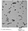
[0083] 本明細書で用いる場合、「シェル」という用語は、コア上に堆積された材料、又は、シェル材料の単一の堆積動作から生じる同一もしくは異なる組成のすでに堆積されたシェル上に堆積された材料を指す。正確なシェル厚さは材料並びに前駆体の入力及び変換に依存し、ナノメートル又は単層の単位で記録することができる。本明細書で用いる場合、「ターゲットシェル厚さ」は、必要な前駆体量を計算するために用いられる、意図されたシェル厚さを指す。本明細書で用いる場合、「実際のシェル厚さ」は、合成後に実際に堆積されたシェル材料の量を指し、当技術分野で既知の方法によって測定できる。一例として、実際のシェル厚さは、シェル合成の前後のナノ結晶のTEM画像から決定された粒径を比較することによって測定できる。 [0083] As used herein, the term "shell" is deposited on a material deposited on a core, or on an already deposited shell of the same or different composition resulting from a single deposition operation of the shell material. Refers to the material that has been made. The exact shell thickness depends on the input and conversion of the material and precursor and can be recorded in nanometers or single layer units. As used herein, "target shell thickness" refers to the intended shell thickness used to calculate the required amount of precursor. As used herein, "actual shell thickness" refers to the amount of shell material actually deposited after synthesis and can be measured by methods known in the art. As an example, the actual shell thickness can be measured by comparing the particle sizes determined from the TEM images of the nanocrystals before and after shell synthesis.
[0084] 本明細書で用いる場合、「半値全幅(FWHM:full width at half maximum)」は、量子ドットのサイズ分布の測度である。量子ドットの発光スペクトルは一般にガウス曲線の形状を有する。ガウス曲線の幅はFWHMとして定義され、粒子のサイズ分布の理解を与える。より小さいFWHMは、より狭い量子ドットナノ結晶サイズ分布に対応する。FWHMは発光波長極大にも依存する。 [0084] As used herein, "full width at half maximum (FWHM)" is a measure of the size distribution of quantum dots. The emission spectrum of quantum dots generally has the shape of a Gaussian curve. The width of the Gaussian curve is defined as FWHM and gives an understanding of the size distribution of particles. The smaller FWHM corresponds to a narrower quantum dot nanocrystal size distribution. FWHM also depends on the maximum emission wavelength.
[0085] 本明細書で用いる場合、「アルキル」は、示される炭素原子数を有する直鎖又は分岐鎖の飽和脂肪族ラジカルを指す。いくつかの実施形態において、アルキルは、C1−2アルキル、C1−3アルキル、C1−4アルキル、C1−5アルキル、C1−6アルキル、C1−7アルキル、C1−8アルキル、C1−9アルキル、C1−10アルキル、C1−12アルキル、C1−14アルキル、C1−16アルキル、C1−18アルキル、C1−20アルキル、C8−20アルキル、C12−20アルキル、C14−20アルキル、C16−20アルキル、又はC18−20アルキルである。例えばC1−6アルキルは、限定ではないが、メチル、エチル、プロピル、イソプロピル、ブチル、イソブチル、sec−ブチル、tert−ブチル、ペンチル、イソペンチル、及びヘキシルを含む。いくつかの実施形態では、アルキルは、オクチル、ノニル、デシル、ウンデシル、ドデシル、トリデシル、テトラデシル、ペンタデシル、ヘキサデシル、ヘプタデシル、オクタデシル、ノナデシル、又はイコサニルである。 [0085] As used herein, "alkyl" refers to a linear or branched saturated aliphatic radical having the indicated number of carbon atoms. In some embodiments, the alkyl is C 1-2 alkyl, C 1-3 alkyl, C 1-4 alkyl, C 1-5 alkyl, C 1-6 alkyl, C 1-7 alkyl, C 1-8. Alkyl, C 1-9 alkyl, C 1-10 alkyl, C 1-12 alkyl, C 1-14 alkyl, C 1-16 alkyl, C 1-18 alkyl, C 1-20 alkyl, C 8-20 alkyl, C 12-20 alkyl, C 14-20 alkyl, C 16-20 alkyl, or C 18-20 alkyl. For example, C 1-6 alkyl includes, but is not limited to, methyl, ethyl, propyl, isopropyl, butyl, isobutyl, sec-butyl, tert-butyl, pentyl, isopentyl, and hexyl. In some embodiments, the alkyl is octyl, nonyl, decyl, undecylic, dodecyl, tridecylic, tetradecyl, pentadecyl, hexadecyl, heptadecyl, octadecyl, nonadecylic, or icosanyl.
[0086] 特に他の明確な指示がない限り、本明細書に列挙した範囲は、始めの値と終わりの値を含む(inclusive)。 [0086] Unless otherwise specified, the ranges listed herein are inclusive.
[0087] 本明細書では、様々な追加の用語が定義されるか、又は他の方法で特徴付けられる。 [0087] Various additional terms are defined or otherwise characterized herein.
コアの生成
[0088] 多種多様なナノ構造のコロイド合成のための方法は当技術分野において既知である。そのような方法は、例えば、生成されるナノ構造のサイズ及び/又は形状の分布を制御するため、ナノ構造の成長を制御するための技法を含む。
Core generation
[0088] Methods for colloidal synthesis of a wide variety of nanostructures are known in the art. Such methods include techniques for controlling the growth of nanostructures, for example, in order to control the size and / or shape distribution of the nanostructures produced.
[0089] 典型的なコロイド合成では、前駆体を急速に注入し、高温溶液(例えば高温溶媒及び/又は界面活性剤)中で熱分解することによって、半導体ナノ構造が生成される。前駆体は同時に又は順次注入することができる。前駆体は急速に反応して核を形成する。典型的に注入/核生成温度よりも低い成長温度で、核にモノマーを加えることによって、ナノ構造の成長が生じる。 [0089] In typical colloidal synthesis, semiconductor nanostructures are produced by rapidly injecting precursors and pyrolyzing them in hot solutions (eg, hot solvents and / or surfactants). Precursors can be injected simultaneously or sequentially. Precursors react rapidly to form nuclei. Nanostructure growth occurs by adding the monomer to the nucleus, typically at a growth temperature below the injection / nucleation temperature.
[0090] 配位子はナノ構造表面と相互作用する。成長温度において、配位子はナノ構造表面に対して迅速に吸着及び脱着することで、成長中のナノ構造の凝集を抑制しながら、ナノ構造に対する原子の追加及び/又は除去を可能とする。一般に、ナノ構造表面と弱く配位結合する配位子はナノ構造の急速な成長を可能とする一方で、ナノ構造表面とより強く結合する配位子ではナノ構造成長が遅くなる。また、配位子は、前駆体の1つ(又はそれ以上)と相互作用してナノ構造成長を遅くする可能性がある。 [0090] The ligand interacts with the nanostructured surface. At growth temperature, the ligand rapidly adsorbs and desorbs to the surface of the nanostructure, allowing the addition and / or removal of atoms to the nanostructure while suppressing the aggregation of the growing nanostructure. In general, ligands that are weakly coordinated to the nanostructured surface allow rapid growth of the nanostructure, while ligands that are more strongly coordinated to the nanostructured surface slow down the growth of the nanostructure. Ligsands can also interact with one (or more) of the precursors to slow nanostructure growth.
[0091] 単一の配位子の存在下でのナノ構造成長は通常、球形ナノ構造を生じる。しかしながら、2つ以上の配位子の混合物を用いると、例えば2つ(又はそれ以上)の配位子が成長中のナノ構造の異なる結晶面に異なるように吸着する場合、非球形ナノ構造を生成できるように成長を制御することが可能となる。 [0091] Nanostructure growth in the presence of a single ligand usually results in spherical nanostructures. However, when a mixture of two or more ligands is used, for example, when two (or more) ligands are differently adsorbed to different crystal planes of the growing nanostructure, the non-spherical nanostructure can be obtained. It is possible to control the growth so that it can be generated.
[0092] このように、多数のパラメータがナノ構造の成長に影響を及ぼすことが知られており、これらを個別に又は組み合わせて操作することで、生成されるナノ構造のサイズ及び/又は形状の分布を制御できる。これらには、例えば温度(核生成及び/又は成長)、前駆体の組成、時間に依存する前駆体濃度、前駆体の相互の比、界面活性剤の組成、界面活性剤の数、及び1又は複数の界面活性剤の相互の比及び/又は前駆体に対する比が含まれる。 [0092] Thus, it is known that a large number of parameters influence the growth of nanostructures, and by manipulating them individually or in combination, the size and / or shape of the nanostructures produced. You can control the distribution. These include, for example, temperature (nuclear formation and / or growth), precursor composition, time-dependent precursor concentration, ratio of precursors to each other, surfactant composition, number of surfactants, and 1 or Includes ratios of multiple surfactants to each other and / or to precursors.
[0093] II−VI族のナノ構造の合成は、米国特許第6,225,198号、第6,322,901号、第6,207,229号、第6,607,829号、第7,060,243号、第7,374,824号、第6,861,155号、第7,125,605号、第7,566,476号、第8,158,193号、及び第8,101,234号、並びに、米国特許出願公報第2011/0262752号及び第2011/0263062号に記載されている。いくつかの実施形態では、コアは、ZnO、ZnSe、ZnS、ZnTe、CdO、CdSe、CdS、CdTe、HgO、HgSe、HgS、及びHgTeから成る群から選択されたII−VI族ナノ結晶である。いくつかの実施形態では、コアは、ZnSe、ZnS、CdSe、及びCdSから成る群から選択されたナノ結晶である。 [0093] The synthesis of group II-VI nanostructures is described in US Pat. Nos. 6,225,198, 6,322,901, 6,207,229, 6,607,829,7. , 060, 243, 7, 374, 824, 6,861,155, 7,125,605, 7,566,476, 8,158,193, and 8, 101,234, as well as US Patent Application Publication Nos. 2011/0262752 and 2011/0263062. In some embodiments, the core is a II-VI group nanocrystal selected from the group consisting of ZnO, ZnSe, ZnS, ZnTe, CdO, CdSe, CdS, CdTe, HgO, HgSe, HgS, and HgTe. In some embodiments, the core is a nanocrystal selected from the group consisting of ZnSe, ZnS, CdSe, and CdS.
[0094] CdSe及びCdS量子ドットのようなII−VI族ナノ構造は望ましい発光挙動を示すことができるが、カドミウムの毒性等の問題によって、そのようなナノ構造を使用できる用途は限定される。従って、良好な発光特性を有する毒性の低い代替案が極めて望ましい。一般にIII−V族ナノ構造、具体的にはInP系ナノ構造は、発光範囲が一致するためにカドミウム系材料の最良の代替案として知られている。 II-VI group nanostructures such as CdSe and CdS quantum dots can exhibit desirable luminescence behavior, but problems such as cadmium toxicity limit the use of such nanostructures. Therefore, a less toxic alternative with good luminescence properties is highly desirable. Group III-V nanostructures, specifically InP-based nanostructures, are generally known as the best alternatives to cadmium-based materials due to their matching emission ranges.
[0095] いくつかの実施形態において、ナノ構造はカドミウムフリーである。本明細書で用いる場合、「カドミウムフリー(free of cadmium)」という用語は、ナノ構造に含まれるカドミウムが100重量ppm未満であることを意図している。特定有害物質使用制限(RoHS:Restriction of Hazardous Substances)に従った定義は、未加工の(raw)均質前駆体材料中のカドミウムが0.01重量%(100ppm)以下でなければならないと要求している。本発明のカドミウムフリーのナノ構造におけるカドミウムレベルは、前駆体材料中の微量金属濃度によって限定される。カドミウムフリーのナノ構造の前駆体材料における微量金属(カドミウムを含む)濃度は、誘導結合プラズマ質量分析(ICP−MS:inductively coupled plasma mass spectroscopy)によって測定することができ、10億分の1(ppb)レベルである。いくつかの実施形態では、「カドミウムフリー」のナノ構造は、約50ppm未満、約20ppm未満、約10ppm未満、又は約1ppm未満のカドミウムを含む。 [0095] In some embodiments, the nanostructures are cadmium-free. As used herein, the term "free of cadmium" is intended to contain less than 100 weight ppm of cadmium in the nanostructures. The definition according to the Restriction of Hazardous Substances (RoHS) requires that cadmium in the raw (raw) homogeneous precursor material be 0.01% by weight (100 ppm) or less. There is. The cadmium level in the cadmium-free nanostructures of the present invention is limited by the concentration of trace metals in the precursor material. Trace metal (including cadmium) concentrations in cadmium-free nanostructured precursor materials can be measured by inductively coupled plasma mass spectrometry (ICP-MS) and is one billionth (ppb). ) Level. In some embodiments, the "cadmium-free" nanostructure comprises less than about 50 ppm, less than about 20 ppm, less than about 10 ppm, or less than about 1 ppm cadmium.
[0096] いくつかの実施形態において、コアはIII−V族ナノ構造である。いくつかの実施形態において、コアは、BN、BP、BAs、BSb、AlN、AlP、AlAs、AlSb、GaN、GaP、GaAs、GaSb、InN、InP、InAs、及びInSbから成る群から選択されたIII−Vナノ結晶である。いくつかの実施形態において、コアはInPナノ結晶である。 [0096] In some embodiments, the core is a III-V nanostructure. In some embodiments, the core is selected from the group consisting of BN, BP, BAs, BSb, AlN, AlP, AlAs, AlSb, GaN, GaP, GaAs, GaSb, InN, InP, InAs, and InSb III. -V nanocrystals. In some embodiments, the core is an InP nanocrystal.
[0097] III−Vナノ構造の合成は、米国特許第5,505,928号、第6,306,736号、第6,576,291号、第6,788,453号、第6,821,337号、第7,138,098号、第7,557,028号、第8,062,967号、第7,645,397号、及び第8,282,412号、及び米国特許出願公報第2015/236195号に記載されている。また、III−V族ナノ構造の合成は、Wells, R. L等の「The use of tris(trimethylsilyl)arsine to prepare gallium arsenide and indium arsenide」Chem. Mater. 1:4-6(1989)、及び、Guzelian, A. A.等の「Colloidal chemical synthesis and characterization of InAs nanocrystal quantum dots」Appl. Phys. Lett. 69:1432-1434(1996)にも記載されている。 [0097] The synthesis of III-V nanostructures is described in US Pat. Nos. 5,505,928, 6,306,736, 6,576,291, 6,788,453, 6,821. , 337, 7,138,098, 7,557,028, 8,062,967, 7,645,397, and 8,282,412, and US Patent Application Publications. No. 2015/236195. The synthesis of group III-V nanostructures is described in "The use of tris (trimethylsilyl) arsine to prepare gallium arsenide and indium arsenide" by Wells, R. L., Chem. Mater. 1: 4-6 (1989), and , Guzelian, AA et al., "Colloidal chemical synthesis and characterization of InAs nanocrystal quantum dots" Appl. Phys. Lett. 69: 1432-1434 (1996).
[0098] InP系ナノ構造の合成は、例えば、Xie, R.等の「Colloidal InP nanocrystals as efficient emitters covering blue to near-infrared」J. Am. Chem. Soc. 129:15432-15433(2007); Micic, O.I.等の「Core-shell quantum dots of lattice-matched ZnCdSe2 shells on InP cores: Experiment and theory」J. Phys. Chem. B 104:12149-12156 (2000);Liu, Z.等の「Coreduction colloidal synthesis of III-V nanocrystals: The case of InP」Angew. Chem. Int. Ed. Engl. 47:3540-3542 (2008);Li, L.等の「Economic synthesis of high quality InP nanocrystals using calcium phosphide as the phosphorus precursor」Chem. Mater. 20:2621-2623 (2008);D. Battaglia and X. Pengの「Formation of high quality InP and InAs nanocrystals in a noncoordinating solvent」Nano Letters 2:1027-1030 (2002);Kim, S.等の「Highly luminescent InP/GaP/ZnS nanocrystals and their application to white light-emitting diodes」J. Am. Chem. Soc. 134:3804-3809 (2012);Nann, T.等の「Water splitting by visible light: A nanophotocathode for hydrogen production」Angew. Chem. Int. Ed. 49: 1574-1577 (2010);Borchert, H.等の「Investigation of ZnS passivated InP nanocrystals by XPS」Nano Letters 2:151-154 (2002):L. Li and P. Reissmp「One-pot synthesis of highly luminescent InP/ZnS nanocrystals without precursor injection」J. Am. Chem. Soc. 130:11588-11589 (2008);Hussain, S.等の「One-pot fabrication of high-quality InP/ZnS (core/shell) quantum dots and their application to cellular imaging」Chemphyschem. 10:1466-1470 (2009);Xu, S.等の「Rapid synthesis of high-quality InP nanocrystals」J. Am. Chem. Soc. 128:1054-1055 (2006);Micic, O.I.等の「Size-dependent spectroscopy of InP quantum dots」J. Phys. Chem. B 101:4904-4912 (1997);Haubold, S.等の「Strongly luminescent InP/ZnS core-shell nanoparticles」Chemphyschem. 5:331-334 (2001);CrosGagneux, A.等の「Surface chemistry of InP quantum dots: A comprehensive study」J. Am. Chem. Soc. 132:18147-18157 (2010);Micic, O.I.等の「Synthesis and characterization of InP, GaP, and GalnP2quantum dots」J. Phys. Chem. 99:7754-7759 (1995);Guzelian, A.A.等の「Synthesis of size-selected, surface-passivated InP nanocrystals」J. Phys. Chem. 100:7212-7219 (1996);Lucey, D.W.等の「Monodispersed InP quantum dots prepared by colloidal chemistry in a non-coordinating solvent」Chem. Mater. 17:3754-3762 (2005);Lim, J.等の「InP@ZnSeS, core@composition gradient shell quantum dots with enhanced stability」Chem. Mater. 23:4459-4463 (2011);及び、Zan, F.等の「Experimental studies on blinking behavior of single InP/ZnS quantum dots: Effects of synthetic conditions and UV irradiation」J. Phys. Chem. C 116:394-3950 (2012)に記載されている。しかしながら、こういった努力は、高い収率を有するInPナノ構造の生成において限られた成功を収めたに過ぎない。 [0098] The synthesis of InP-based nanostructures is described, for example, in "Colloidal InP nanocrystals as efficient emitters covering blue to near-infrared" by Xie, R. et al., J. Am. Chem. Soc. 129: 15432-15433 (2007); "Core-shell quantum dots of lattice-matched ZnCdSe 2 shells on InP cores: Experiment and theory" by Micic, OI, etc. J. Phys. Chem. B 104: 12149-12156 (2000); colloidal synthesis of III-V nanocrystals: The case of InP ”Angew. Chem. Int. Ed. Engl. 47: 3540-3542 (2008);“ Economic synthesis of high quality InP nanocrystals using calcium phosphide as The phosphorus precursor "Chem. Mater. 20: 2621-2623 (2008); D. Battaglia and X. Peng's" Formation of high quality InP and InAs nanocrystals in a noncoordinating solvent "Nano Letters 2: 1027-1030 (2002); Kim, S. et al. "Highly luminescent InP / GaP / ZnS nanocrystals and their application to white light-emitting diodes" J. Am. Chem. Soc. 134: 3804-3809 (2012); Nann, T. et al. "Water" splitting by visible light: A nanophotocathode for infrared production "Angew. Chem. Int. Ed. 49: 1574-1577 (2010); Borcher t, H. et al. "Investigation of ZnS passivated InP nanocrystals by XPS" Nano Letters 2: 151-154 (2002): L. Li and P. Reissmp "One-pot synthesis of highly luminescent InP / ZnS nanocrystals without precursor injection" J. Am. Chem. Soc. 130: 11588-11589 (2008); "One-pot passion of high-quality InP / ZnS (core / shell) quantum dots and their application to cellular imaging" Chemphyschem by Hussain, S. et al. . 10: 1466-1470 (2009); "Rapid synthesis of high-quality InP nanocrystals" by Xu, S., etc. J. Am. Chem. Soc. 128: 1054-1055 (2006); "Size" by Micic, OI, etc. -dependent spectroscopy of InP quantum dots "J. Phys. Chem. B 101: 4904-4912 (1997);" Strongly luminescent InP / ZnS core-shell nanoparticles "Chemphyschem. 5: 331-334 (2001) by Haubold, S. et al. ); "Surface chemistry of InP quantum dots: A comprehensive study" by Cross Gagneux, A. et al. J. Am. Chem. Soc. 132: 18147-18157 (2010); "Synthesis and characterization of InP, GaP" by Micic, OI et al. , and GalnP 2 quantum dots ”J. Phys. Chem. 99: 7754-7759 (1995);“ Synthesis of size-selected, surface-passivated InP ”by Guzelian, AA, etc. "nanocrystals" J. Phys. Chem. 100: 7212-7219 (1996); "Monodispersed InP quantum dots prepared by colloidal chemistry in a non-coordinating solvent" Chem. Mater. 17: 3754-3762 (2005) "InP @ ZnSeS, core @ composition gradient shell quantum dots with enhanced stability" by Lim, J. et al. Chem. Mater. 23: 4459-4463 (2011); and "Experimental studies on blinking behavior" by Zan, F. et al. of single InP / ZnS quantum dots: Effects of synthetic conditions and UV irradiation ”J. Phys. Chem. C 116: 394-3950 (2012). However, these efforts have had only limited success in producing InP nanostructures with high yields.
[0099] いくつかの実施形態において、コアはドープされている。いくつかの実施形態において、ナノ結晶コアのドーパントは、1つ以上の遷移金属を含む金属を含む。いくつかの実施形態において、ドーパントは、Ti、Zr、Hf、V、Nb、Ta、Cr、Mo、W、Mn、Tc、Re、Fe、Ru、Os、Co、Rh、Ir、Ni、Pd、Pt、Cu、Ag、Au、及びそれらの組み合わせから成る群から選択された遷移金属である。いくつかの実施形態において、ドーパントは非金属を含む。いくつかの実施形態において、ドーパントは、ZnS、ZnSe、ZnTe、CdSe、CdS、CdTe、HgS、HgSe、HgTe、CuInS2、CuInSe2、AlN、AlP、AlAs、GaN、GaP、又はGaAsである。 [0099] In some embodiments, the core is doped. In some embodiments, the dopant of the nanocrystal core comprises a metal containing one or more transition metals. In some embodiments, the dopants are Ti, Zr, Hf, V, Nb, Ta, Cr, Mo, W, Mn, Tc, Re, Fe, Ru, Os, Co, Rh, Ir, Ni, Pd, A transition metal selected from the group consisting of Pt, Cu, Ag, Au, and combinations thereof. In some embodiments, the dopant comprises a non-metal. In some embodiments, the dopant is ZnS, ZnSe, ZnTe, CdSe, CdS, CdTe, HgS, HgSe, HgTe, CuInS 2 , CuInSe 2 , AlN, AlP, AlAs, GaN, GaP, or GaAs.
[0100] いくつかの実施形態において、コアはシェルの堆積前に精製される。いくつかの実施形態において、コアはろ過されてコア溶液から沈殿物が除去される。 [0100] In some embodiments, the core is purified prior to shell deposition. In some embodiments, the core is filtered to remove the precipitate from the core solution.
[0101] いくつかの実施形態では、シェルの堆積前にコアに酸エッチングステップを行う。 [0101] In some embodiments, an acid etching step is performed on the core prior to shell deposition.
[0102] いくつかの実施形態において、コアの直径は量子閉じ込めを用いて決定される。量子ドットのようなゼロ次元ナノ結晶における量子閉じ込めは、結晶境界内の電子の空間的閉じ込めによって生じる。材料の直径が波動関数のドブロイ波長と同じ大きさになったら、量子閉じ込めを観察することができる。ナノ粒子の電子特性及び光学特性は、バルク材料のものから大きく逸脱する。粒子の波長に比べて閉じ込め寸法が大きい場合、粒子は自由であるようにふるまう。この状態の間、バンドギャップは連続エネルギ状態によるその最初のエネルギに留まる。しかしながら、閉じ込め寸法が縮小して、典型的にナノスケールである特定の限界に達すると、エネルギスペクトルは離散的になる。その結果、バンドギャップはサイズに依存するようになる。 [0102] In some embodiments, the diameter of the core is determined using quantum confinement. Quantum confinement in zero-dimensional nanocrystals such as quantum dots is caused by spatial confinement of electrons within the crystal boundary. Quantum confinement can be observed when the diameter of the material is as large as the de Broglie wavelength of the wave function. The electronic and optical properties of nanoparticles deviate significantly from those of bulk materials. If the confinement size is large relative to the wavelength of the particle, the particle behaves as if it were free. During this state, the bandgap remains at its initial energy due to the continuous energy state. However, as the confinement dimensions shrink to reach certain limits, typically nanoscale, the energy spectrum becomes discrete. As a result, the bandgap becomes size dependent.
シェルの生成
[0103] いくつかの実施形態において、本発明のナノ構造はコアと少なくとも1つのシェルとを含む。いくつかの実施形態において、本発明のナノ構造はコアと少なくとも2つのシェルとを含む。シェルは、例えばナノ構造の量子収率及び/又は安定性を増大させることができる。いくつかの実施形態において、コア及びシェルは異なる材料を含む。いくつかの実施形態において、ナノ構造は異なるシェル材料のシェルを含む。
Shell generation
[0103] In some embodiments, the nanostructures of the invention include a core and at least one shell. In some embodiments, the nanostructures of the invention include a core and at least two shells. The shell can, for example, increase the quantum yield and / or stability of the nanostructure. In some embodiments, the core and shell contain different materials. In some embodiments, the nanostructure comprises a shell of different shell material.
[0104] いくつかの実施形態において、コア又はコア/シェル(複数のシェル)構造の上に、II族及びVI族の元素の混合物を含むシェルが堆積される。いくつかの実施形態では、亜鉛源、セレン源、硫黄源、テルル源、及びカドミウム源のうち少なくとも2つの混合物によって、シェルが堆積される。いくつかの実施形態では、亜鉛源、セレン源、硫黄源、テルル源、及びカドミウム源のうち2つの混合物によって、シェルが堆積される。いくつかの実施形態では、亜鉛源、セレン源、硫黄源、テルル源、及びカドミウム源のうち3つの混合物によって、シェルが堆積される。いくつかの実施形態において、シェルは、亜鉛及び硫黄;亜鉛及びセレン;亜鉛、硫黄、及びセレン;亜鉛及びテルル;亜鉛、テルル、及び硫黄;亜鉛、テルル、及びセレン;亜鉛、カドミウム、及び硫黄;亜鉛、カドミウム、及びセレン;カドミウム及び硫黄;カドミウム及びセレン;カドミウム、セレン、及び硫黄;カドミウム、亜鉛、及び硫黄;カドミウム、亜鉛、及びセレン;又は、カドミウム、亜鉛、硫黄、及びセレンから成る。 [0104] In some embodiments, a shell containing a mixture of Group II and Group VI elements is deposited on a core or core / shell structure. In some embodiments, the shell is deposited by a mixture of at least two of a zinc source, a selenium source, a sulfur source, a tellurium source, and a cadmium source. In some embodiments, the shell is deposited by a mixture of two sources: a zinc source, a selenium source, a sulfur source, a tellurium source, and a cadmium source. In some embodiments, the shell is deposited by a mixture of three sources: zinc source, selenium source, sulfur source, tellurium source, and cadmium source. In some embodiments, the shell is zinc and sulfur; zinc and selenium; zinc, sulfur, and selenium; zinc and tellurium; zinc, tellurium, and sulfur; zinc, tellurium, and selenium; zinc, cadmium, and sulfur; Zinc, cadmium, and selenium; cadmium and sulfur; cadmium and selenium; cadmium, selenium, and sulfur; cadmium, zinc, and sulfur; cadmium, zinc, and selenium; or cadmium, zinc, sulfur, and selenium.
[0105] いくつかの実施形態において、シェルは、シェル材料の2つ以上の単層を含む。単層の数は全ナノ構造の平均である。従って、シェル内の単層の数は小数である可能性がある。いくつかの実施形態において、シェル内の単層の数は、0.25から10、0.25から8、0.25から7、0.25から6、0.25から5、0.25から4、0.25から3、0.25から2、2から10、2から8、2から7、2から6、2から5、2から4、2から3、3から10、3から8、3から7、3から6、3から5、3から4、4から10、4から8、4から7、4から6、4から5、5から10、5から8、5から7、5から6、6から10、6から8、6から7、7から10、7から8、又は8から10である。いくつかの実施形態では、シェルは3から5の単層を含む。 [0105] In some embodiments, the shell comprises two or more single layers of shell material. The number of single layers is the average of all nanostructures. Therefore, the number of single layers in the shell can be decimal. In some embodiments, the number of monolayers in the shell ranges from 0.25 to 10, 0.25 to 8, 0.25 to 7, 0.25 to 6, 0.25 to 5, 0.25. 4, 0.25 to 3, 0.25 to 2, 2 to 10, 2 to 8, 2 to 7, 2 to 6, 2 to 5, 2 to 4, 2 to 3, 3 to 10, 3 to 8, 3 to 7, 3 to 6, 3 to 5, 3 to 4, 4 to 10, 4 to 8, 4 to 7, 4 to 6, 4 to 5, 5 to 10, 5 to 8, 5 to 7, 5 6, 6 to 10, 6 to 8, 6 to 7, 7 to 10, 7 to 8, or 8 to 10. In some embodiments, the shell comprises 3 to 5 monolayers.
[0106] シェルの厚さは、提供する前駆体の量を変えることによって制御できる。所与のシェル厚さを得るため、前駆体のうち少なくとも1つは任意選択的に、成長反応が実質的に完了した時に所定の厚さのシェルが得られるような量で提供される。2つ以上の異なる前駆体が提供される場合、各前駆体の量を限定するか、又は前駆体のうち1つを限定量で提供すると共に他の前駆体を余分に提供する。 [0106] Shell thickness can be controlled by varying the amount of precursor provided. To obtain a given shell thickness, at least one of the precursors is optionally provided in an amount such that a shell of a given thickness is obtained when the growth reaction is substantially completed. When two or more different precursors are provided, the amount of each precursor is limited, or one of the precursors is provided in a limited amount and the other precursors are provided in excess.
[0107] 各シェルの厚さは当業者に既知の技法を用いて決定することができる。いくつかの実施形態において、各シェルの厚さは、各シェルを追加する前後のナノ構造の平均直径を比較することによって決定される。いくつかの実施形態では、各シェルを追加する前後のナノ構造の平均直径はTEMによって決定される。いくつかの実施形態において、各シェルの厚さは、0.05nmから3.5nm、0.05nmから2nm、0.05nmから0.9nm、0.05nmから0.7nm、0.05nmから0.5nm、0.05nmから0.3nm、0.05nmから0.1nm、0.1nmから3.5nm、0.1nmから2nm、0.1nmから0.9nm、0.1nmから0.7nm、0.1nmから0.5nm、0.1nmから0.3nm、0.3nmから3.5nm、0.3nmから2nm、0.3nmから0.9nm、0.3nmから0.7nm、0.3nmから0.5nm、0.5nmから3.5nm、0.5nmから2nm、0.5nmから0.9nm、0.5nmから0.7nm、0.7nmから3.5nm、0.7nmから2nm、0.7nmから0.9nm、0.9nmから3.5nm、0.9nmから2nm、又は2nmから3.5nmである。 [0107] The thickness of each shell can be determined using techniques known to those of skill in the art. In some embodiments, the thickness of each shell is determined by comparing the average diameter of the nanostructures before and after adding each shell. In some embodiments, the average diameter of the nanostructures before and after adding each shell is determined by TEM. In some embodiments, the thickness of each shell is 0.05 nm to 3.5 nm, 0.05 nm to 2 nm, 0.05 nm to 0.9 nm, 0.05 nm to 0.7 nm, 0.05 nm to 0. 5 nm, 0.05 nm to 0.3 nm, 0.05 nm to 0.1 nm, 0.1 nm to 3.5 nm, 0.1 nm to 2 nm, 0.1 nm to 0.9 nm, 0.1 nm to 0.7 nm, 0. 1 nm to 0.5 nm, 0.1 nm to 0.3 nm, 0.3 nm to 3.5 nm, 0.3 nm to 2 nm, 0.3 nm to 0.9 nm, 0.3 nm to 0.7 nm, 0.3 nm to 0. From 5 nm, 0.5 nm to 3.5 nm, 0.5 nm to 2 nm, 0.5 nm to 0.9 nm, 0.5 nm to 0.7 nm, 0.7 nm to 3.5 nm, 0.7 nm to 2 nm, 0.7 nm It is 0.9 nm, 0.9 nm to 3.5 nm, 0.9 nm to 2 nm, or 2 nm to 3.5 nm.
[0108] いくつかの実施形態において、各シェルは少なくとも1つのナノ構造配位子の存在下で合成される。配位子は例えば、溶媒又はポリマー中のナノ構造の混和性を向上させ(ナノ構造が凝集しないように組成物全体に分散させることを可能とする)、ナノ構造の量子収率を増大させ、及び/又は(例えばナノ構造がマトリックス内に組み込まれた場合)ナノ構造のルミネッセンスを保存することができる。いくつかの実施形態では、コア合成及びシェル合成のための1又は複数の配位子は同一である。いくつかの実施形態では、コア合成及びシェル合成のための1又は複数の配位子は異なる。合成の後、ナノ構造の表面上の配位子は、他の所望の特性を有する異なる配位子と交換することができる。配位子の例は、米国特許第7,572,395号、第8,143,703号、第8,425,803号、第8,563,133号、第8,916,064号、第9,005,480号、第9,139,770号、及び第9,169,435号、及び米国特許出願公報第2008/0118755号に開示されている。 [0108] In some embodiments, each shell is synthesized in the presence of at least one nanostructured ligand. The ligands, for example, improve the compatibility of the nanostructures in the solvent or polymer (allowing them to be dispersed throughout the composition so that the nanostructures do not aggregate), increase the quantum yield of the nanostructures, and increase the quantum yield of the nanostructures. And / or (eg, when the nanostructure is incorporated into the matrix) the luminosence of the nanostructure can be preserved. In some embodiments, the one or more ligands for core synthesis and shell synthesis are identical. In some embodiments, the one or more ligands for core synthesis and shell synthesis are different. After synthesis, the ligands on the surface of the nanostructure can be exchanged for different ligands with other desired properties. Examples of ligands are U.S. Pat. Nos. 7,572,395, 8,143,703, 8,425,803, 8,563,133, 8,916,064, No. It is disclosed in 9,005,480, 9,139,770, and 9,169,435, and US Patent Application Publication No. 2008/0118755.
[0109] シェルの合成に適した配位子は当業者によって知られている。いくつかの実施形態において、配位子は、ラウリン酸、カプロン酸、ミリスチン酸、パルミチン酸、ステアリン酸、及びオレイン酸から成る群から選択された脂肪酸である。いくつかの実施形態において、配位子は、トリオクチルホスフィンオキシド(TOPO)、トリオクチルホスフィン(TOP)、ジフェニルホスフィン(DPP)、トリフェニルホスフィンオキシド、及びトリブチルホスフィンオキシドから選択された有機ホスフィン又は有機ホスフィンオキシドである。いくつかの実施形態において、配位子は、ドデシルアミン、オレイルアミン、ヘキサデシルアミン、ジオクチルアミン、及びオクタデシルアミンから成る群から選択されたアミンである。いくつかの実施形態において、配位子は、トリブチルホスフィン、オレイン酸、又はオレイン酸亜鉛である。 Suitable ligands for the synthesis of shells are known to those of skill in the art. In some embodiments, the ligand is a fatty acid selected from the group consisting of lauric acid, caproic acid, myristic acid, palmitic acid, stearic acid, and oleic acid. In some embodiments, the ligand is an organic phosphine or organic selected from trioctylphosphine oxide (TOPO), trioctylphosphine (TOP), diphenylphosphine (DPP), triphenylphosphine oxide, and tributylphosphine oxide. Phosphine oxide. In some embodiments, the ligand is an amine selected from the group consisting of dodecylamine, oleylamine, hexadecylamine, dioctylamine, and octadecylamine. In some embodiments, the ligand is tributylphosphine, oleic acid, or zinc oleate.
[0110] いくつかの実施形態において、各シェルは配位子の混合物の存在下で生成される。いくつかの実施形態において、各シェルは、2、3、4、5、又は6の異なる配位子を含む混合物の存在下で生成される。いくつかの実施形態において、各シェルは3つの異なる配位子を含む混合物の存在下で生成される。いくつかの実施形態において、配位子の混合物は、トリブチルホスフィン、オレイン酸、及びオレイン酸亜鉛を含む。 [0110] In some embodiments, each shell is produced in the presence of a mixture of ligands. In some embodiments, each shell is produced in the presence of a mixture containing 2, 3, 4, 5, or 6 different ligands. In some embodiments, each shell is produced in the presence of a mixture containing three different ligands. In some embodiments, the mixture of ligands comprises tributylphosphine, oleic acid, and zinc oleate.
[0111] いくつかの実施形態において、各シェルは溶媒の存在下で生成される。いくつかの実施形態において、溶媒は、1−オクタデセン、1−ヘキサデセン、1−エイコセン、エイコサン、オクタデカン、ヘキサデカン、テトラデカン、スクアレン、スクアラン、トリオクチルホスフィンオキシド、及びジオクチルエーテルから成る群から選択される。いくつかの実施形態において、溶媒は1−オクタデセンである。 [0111] In some embodiments, each shell is produced in the presence of a solvent. In some embodiments, the solvent is selected from the group consisting of 1-octadecane, 1-hexadecane, 1-eicosene, icosane, octadecane, hexadecane, tetradecane, squalene, squalene, trioctylphosphine oxides, and dioctyl ethers. In some embodiments, the solvent is 1-octadecene.
[0112] いくつかの実施形態において、コア又はコア/シェル(複数のシェル)とシェル前駆体とを、20℃から310℃、20℃から280℃、20℃から250℃、20℃から200℃、20℃から150℃、20℃から100℃、20℃から50℃、50℃から310℃、50℃から280℃、50℃から250℃、50℃から200℃、50℃から150℃、50℃から100℃、100℃から310℃、100℃から280℃、100℃から250℃、100℃から200℃、100℃から150℃、150℃から310℃、150℃から280℃、150℃から250℃、150℃から200℃、200℃から310℃、200℃から280℃、200℃から250℃、250℃から310℃、250℃から280℃、又は280℃から310℃の追加温度で接触させる。いくつかの実施形態では、コア又はコア/シェル(複数のシェル)とシェル前駆体とを、20℃から100℃の追加温度で接触させる。 [0112] In some embodiments, the core or core / shell (s) and shell precursors are 20 ° C to 310 ° C, 20 ° C to 280 ° C, 20 ° C to 250 ° C, 20 ° C to 200 ° C. , 20 ° C to 150 ° C, 20 ° C to 100 ° C, 20 ° C to 50 ° C, 50 ° C to 310 ° C, 50 ° C to 280 ° C, 50 ° C to 250 ° C, 50 ° C to 200 ° C, 50 ° C to 150 ° C, 50. ° C to 100 ° C, 100 ° C to 310 ° C, 100 ° C to 280 ° C, 100 ° C to 250 ° C, 100 ° C to 200 ° C, 100 ° C to 150 ° C, 150 ° C to 310 ° C, 150 ° C to 280 ° C, 150 ° C Contact at additional temperatures of 250 ° C, 150 ° C to 200 ° C, 200 ° C to 310 ° C, 200 ° C to 280 ° C, 200 ° C to 250 ° C, 250 ° C to 310 ° C, 250 ° C to 280 ° C, or 280 ° C to 310 ° C. Let me. In some embodiments, the core or core / shell (s) and the shell precursor are contacted at an additional temperature of 20 ° C to 100 ° C.
[0113] いくつかの実施形態では、コア又はコア/シェル(複数のシェル)とシェル前駆体とを接触させた後、反応混合物の温度を上げて、200℃から310℃、200℃から280℃、200℃から250℃、200℃から220℃、220℃から310℃、220℃から280℃、220℃から250℃、250℃から310℃、250℃から280℃、又は280℃から310℃の高温にする。いくつかの実施形態では、コア又はコア/シェル(複数のシェル)とシェル前駆体とを接触させた後、反応混合物の温度を上げて250℃から310℃にする。 [0113] In some embodiments, after contacting the core or core / shell (s) with the shell precursor, the temperature of the reaction mixture is increased from 200 ° C to 310 ° C and from 200 ° C to 280 ° C. , 200 ° C to 250 ° C, 200 ° C to 220 ° C, 220 ° C to 310 ° C, 220 ° C to 280 ° C, 220 ° C to 250 ° C, 250 ° C to 310 ° C, 250 ° C to 280 ° C, or 280 ° C to 310 ° C. Bring to high temperature. In some embodiments, after contacting the core or core / shell (s) with the shell precursor, the temperature of the reaction mixture is raised from 250 ° C to 310 ° C.
[0114] いくつかの実施形態では、コア又はコア/シェル(複数のシェル)とシェル前駆体とを接触させた後、温度が高温に到達するのに要する時間は、2分から240分、2分から200分、2分から100分、2分から60分、2分から40分、5分から240、5分から200分、5分から100分、5分から60分、5分から40分、10分から240分、10分から200分、10分から100分、10分から60分、10分から40分、40分から240分、40分から200分、40分から100分、40分から60分、60分から240分、60分から200分、60分から100分、100分から240分、100分から200分、又は200分から240分の間である。 [0114] In some embodiments, the time required for the temperature to reach a high temperature after contacting the core or core / shell (s) with the shell precursor is from 2 minutes to 240 minutes, from 2 minutes. 200 minutes, 2 minutes to 100 minutes, 2 minutes to 60 minutes, 2 minutes to 40 minutes, 5 minutes to 240 minutes, 5 minutes to 200 minutes, 5 minutes to 100 minutes, 5 minutes to 60 minutes, 5 minutes to 40 minutes, 10 minutes to 240 minutes, 10 minutes to 200 minutes. Minutes, 10 minutes to 100 minutes, 10 minutes to 60 minutes, 10 minutes to 40 minutes, 40 minutes to 240 minutes, 40 minutes to 200 minutes, 40 minutes to 100 minutes, 40 minutes to 60 minutes, 60 minutes to 240 minutes, 60 minutes to 200 minutes, 60 minutes to 100 minutes. Between 100 minutes and 240 minutes, 100 minutes and 200 minutes, or 200 minutes and 240 minutes.
[0115] いくつかの実施形態では、コア又はコア/シェル(複数のシェル)とシェル前駆体とを接触させた後、反応混合物の温度が高温に維持されるのは、2分から240分、2分から200分、2分から100分、2分から60分、2分から40分、5分から240分、5分から200分、5分から100分、5分から60分、5分から40分、10分から240分、10分から200分、10分から100分、10分から60分、10分から40分、40分から240分、40分から200分、40分から100分、40分から60分、60分から240分、60分から200分、60分から100分、100分から240分、100分から200分、又は200分から240分の間である。いくつかの実施形態では、コア又はコア/シェル(複数のシェル)とシェル前駆体とを接触させた後、反応混合物の温度が高温に維持されるのは30分から120分の間である。 [0115] In some embodiments, the temperature of the reaction mixture is maintained at a high temperature for 2 to 240 minutes after contacting the core or core / shell (s) with the shell precursor. Minutes to 200 minutes, 2 minutes to 100 minutes, 2 minutes to 60 minutes, 2 minutes to 40 minutes, 5 minutes to 240 minutes, 5 minutes to 200 minutes, 5 minutes to 100 minutes, 5 minutes to 60 minutes, 5 minutes to 40 minutes, 10 minutes to 240 minutes, 10 minutes Minutes to 200 minutes, 10 minutes to 100 minutes, 10 minutes to 60 minutes, 10 minutes to 40 minutes, 40 minutes to 240 minutes, 40 minutes to 200 minutes, 40 minutes to 100 minutes, 40 minutes to 60 minutes, 60 minutes to 240 minutes, 60 minutes to 200 minutes, 60 Between minutes and 100 minutes, 100 minutes and 240 minutes, 100 minutes and 200 minutes, or 200 minutes and 240 minutes. In some embodiments, the temperature of the reaction mixture is maintained at a high temperature between 30 and 120 minutes after contacting the core or core / shell (s) with the shell precursor.
[0116] いくつかの実施形態では、反応混合物にシェル材料前駆体を更に加え、その後高温に維持することによって、追加のシェルを生成する。典型的には、前のシェルの反応が実質的に完了した後(例えば、前の前駆体のうち少なくとも1つが消耗されたかもしくは反応から除去された場合、又は追加の成長が検出できない場合)、追加のシェル前駆体を与える。前駆体の更なる追加によって追加のシェルを生成する。 [0116] In some embodiments, additional shell material precursors are added to the reaction mixture and then maintained at high temperature to produce additional shells. Typically, after the reaction of the previous shell is substantially complete (eg, if at least one of the previous precursors has been depleted or removed from the reaction, or if no additional growth can be detected). Gives an additional shell precursor. Additional shells are generated by adding more precursors.
[0117] いくつかの実施形態では、追加のシェル材料前駆体を追加して更なるシェルを提供する前に、ナノ構造を冷却する。いくつかの実施形態では、シェル材料前駆体を追加して更なるシェルを提供する前に、ナノ構造を高温に維持する。 [0117] In some embodiments, the nanostructures are cooled before adding additional shell material precursors to provide additional shells. In some embodiments, the nanostructures are kept at high temperatures before adding shell material precursors to provide additional shells.
[0118] ナノ構造に充分なシェル層を追加して所望の厚さ及び直径に到達した後、ナノ構造を冷却することができる。いくつかの実施形態では、コア/シェル(複数のシェル)のナノ構造を室温に冷却する。いくつかの実施形態では、有機溶媒を追加して、コア/シェル(複数のシェル)のナノ構造を含む反応混合物を希釈する。 [0118] After adding sufficient shell layer to the nanostructure to reach the desired thickness and diameter, the nanostructure can be cooled. In some embodiments, the core / shell nanostructures are cooled to room temperature. In some embodiments, an organic solvent is added to dilute the reaction mixture containing the core / shell nanostructures.
[0119] いくつかの実施形態において、反応混合物を希釈するため使用される有機溶媒は、エタノール、ヘキサン、ペンタン、トルエン、ベンゼン、ジエチルエーテル、アセトン、酢酸エチル、ジクロロメタン(塩化メチレン)、クロロホルム、ジメチルホルミアミド、又はN−メチルピロリジノンである。いくつかの実施形態において、有機溶媒はトルエンである。 [0119] In some embodiments, the organic solvents used to dilute the reaction mixture are ethanol, hexane, pentane, toluene, benzene, diethyl ether, acetone, ethyl acetate, dichloromethane (methylene chloride), chloroform, dimethyl. Chloroform, or N-methylpyrrolidinone. In some embodiments, the organic solvent is toluene.
[0120] いくつかの実施形態において、コア/シェル(複数のシェル)のナノ構造は単離される。いくつかの実施形態において、コア/シェル(複数のシェル)のナノ構造は、有機溶媒を用いた沈殿によって単離される。いくつかの実施形態において、コア/シェル(複数のシェル)のナノ構造は、エタノールを用いた凝集(flocculation)によって単離される。 [0120] In some embodiments, core / shell nanostructures are isolated. In some embodiments, the core / shell nanostructures are isolated by precipitation with an organic solvent. In some embodiments, the core / shell nanostructures are isolated by flocculation with ethanol.
[0121] 単層の数は、コア/シェル(複数のシェル)のナノ構造のサイズを決定する。コア/シェル(複数のシェル)のナノ構造の大きさは、当業者に既知の技法を用いて決定することができる。いくつかの実施形態において、コア/シェル(複数のシェル)のナノ構造の大きさはTEMを用いて決定される。いくつかの実施形態において、コア/シェル(複数のシェル)のナノ構造の平均直径は、1nmから15nm、1nmから10nm、1nmから9nm、1nmから8nm、1nmから7nm、1nmから6nm、1nmから5nm、5nmから15nm、5nmから10nm、5nmから9nm、5nmから8nm、5nmから7nm、5nmから6nm、6nmから15nm、6nmから10nm、6nmから9nm、6nmから8nm、6nmから7nm、7nmから15nm、7nmから10nm、7nmから9nm、7nmから8nm、8nmから15nm、8nmから10nm、8nmから9nm、9nmから15nm、9nmから10nm、又は10nmから15nmである。いくつかの実施形態では、コア/シェル(複数のシェル)のナノ構造は6nmから7nmの平均直径を有する。 [0121] The number of single layers determines the size of the core / shell nanostructures. The size of the core / shell nanostructure can be determined using techniques known to those of skill in the art. In some embodiments, the size of the core / shell nanostructures is determined using TEM. In some embodiments, the average diameter of the core / shell nanostructure is 1 nm to 15 nm, 1 nm to 10 nm, 1 nm to 9 nm, 1 nm to 8 nm, 1 nm to 7 nm, 1 nm to 6 nm, 1 nm to 5 nm. 5nm to 15nm, 5nm to 10nm, 5nm to 9nm, 5nm to 8nm, 5nm to 7nm, 5nm to 6nm, 6nm to 15nm, 6nm to 10nm, 6nm to 9nm, 6nm to 8nm, 6nm to 7nm, 7nm to 15nm, 7nm From 10 nm, 7 nm to 9 nm, 7 nm to 8 nm, 8 nm to 15 nm, 8 nm to 10 nm, 8 nm to 9 nm, 9 nm to 15 nm, 9 nm to 10 nm, or 10 nm to 15 nm. In some embodiments, the core / shell nanostructures have an average diameter of 6 nm to 7 nm.
[0122] いくつかの実施形態では、追加シェルの堆積前に、コア/シェル(複数のシェル)のナノ構造に酸エッチングステップを行う。 [0122] In some embodiments, acid etching steps are performed on the core / shell nanostructures prior to deposition of additional shells.
ZnSeシェルの生成
[0123] いくつかの実施形態において、コア又はコア/シェル(複数のシェル)のナノ構造上に堆積されるシェルはZnSeシェルである。
Generation of ZnSe shell
[0123] In some embodiments, the shell deposited on the core or core / shell nanostructures is a ZnSe shell.
[0124] いくつかの実施形態において、ZnSeシェルを調製するためコア又はコア/シェル(複数のシェル)のナノ構造に接触させるシェル前駆体は、亜鉛源及びセレン源を含む。 [0124] In some embodiments, shell precursors that are contacted with core or core / shell nanostructures to prepare ZnSe shells include zinc sources and selenium sources.
[0125] いくつかの実施形態において、亜鉛源はジアルキル亜鉛化合物である。いくつかの実施形態において、亜鉛源はカルボン酸亜鉛である。いくつかの実施形態において、亜鉛源は、ジエチル亜鉛、ジメチル亜鉛、酢酸亜鉛、亜鉛アセチルアセトナート、ヨウ化亜鉛、臭化亜鉛、塩化亜鉛、フッ化亜鉛、炭酸亜鉛、シアン化亜鉛、硝酸亜鉛、オレイン酸亜鉛、酸化亜鉛、過酸化亜鉛、過塩素酸亜鉛、硫酸亜鉛、ヘキサン酸亜鉛、オクタン酸亜鉛、ラウリン酸亜鉛、ミリスチン酸亜鉛、パルミチン酸亜鉛、ステアリン酸亜鉛、ジチオカルバミン酸亜鉛、又はそれらの混合物である。いくつかの実施形態において、亜鉛源は、オレイン酸亜鉛、ヘキサン酸亜鉛、オクタン酸亜鉛、ラウリン酸亜鉛、ミリスチン酸亜鉛、パルミチン酸亜鉛、ステアリン酸亜鉛、ジチオカルバミン酸亜鉛、又はそれらの混合物である。いくつかの実施形態において、亜鉛源はオレイン酸亜鉛である。 [0125] In some embodiments, the zinc source is a dialkylzinc compound. In some embodiments, the zinc source is zinc carboxylate. In some embodiments, the zinc source is diethyl zinc, dimethyl zinc, zinc acetate, zinc acetylacetonate, zinc iodide, zinc bromide, zinc chloride, zinc fluoride, zinc carbonate, zinc cyanide, zinc nitrate, Zinc oleate, zinc oxide, zinc peroxide, zinc perchlorate, zinc sulfate, zinc hexanoate, zinc octanate, zinc laurate, zinc myristate, zinc palmitate, zinc stearate, zinc dithiocarbamate, or theirs. It is a mixture. In some embodiments, the zinc source is zinc oleate, zinc hexanoate, zinc octanate, zinc laurate, zinc myristate, zinc palmitate, zinc stearate, zinc dithiocarbamate, or a mixture thereof. In some embodiments, the zinc source is zinc oleate.
[0126] いくつかの実施形態において、セレン源はアルキル置換セレノ尿素(selenourea)である。いくつかの実施形態において、セレン源はホスフィンセレニドである。いくつかの実施形態において、セレン源は、トリオクチルホスフィンセレニド、トリ(n−ブチル)ホスフィンセレニド、トリ(sec−ブチル)ホスフィンセレニド、トリ(tert−ブチル)ホスフィンセレニド、トリメチルホスフィンセレニド、トリフェニルホスフィンセレニド、ジフェニルホスフィンセレニド、フェニルホスフィンセレニド、トリシクロヘキシルホスフィンセレニド、シクロヘキシルホスフィンセレニド、1−オクタンセレノール、1−ドデカンセレノール、セレノフェノール、元素セレン、セレン化水素、ビス(トリメチルシリル)セレニド、セレノ尿素、及びそれらの混合物から選択される。いくつかの実施形態において、セレン源は、トリ(n−ブチル)ホスフィンセレニド、トリ(sec−ブチル)ホスフィンセレニド、トリ(tert−ブチル)ホスフィンセレニドである。いくつかの実施形態において、セレン源はトリオクチルホスフィンセレニドである。 [0126] In some embodiments, the selenium source is an alkyl-substituted selenourea. In some embodiments, the source of selenium is phosphine serenide. In some embodiments, the selenium source is trioctylphosphine serenide, tri (n-butyl) phosphine serenide, tri (sec-butyl) phosphine serenide, tri (tert-butyl) phosphine serenide, trimethylphosphine serenide. Nide, Triphenylphosphine Serenide, Diphenylphosphine Serenide, Phenylphosphine Serenide, Tricyclohexylphosphine Serenide, Cyclohexylphosphine Serenide, 1-octane Serenol, 1-Dodecane Serenol, Serenophenol, Elemental Serene, Hydrogen Selenide , Bis (trimethylsilyl) selenide, serenourea, and mixtures thereof. In some embodiments, the selenium source is tri (n-butyl) phosphine serenide, tri (sec-butyl) phosphine serenide, tri (tert-butyl) phosphine serenide. In some embodiments, the source of selenium is trioctylphosphine serenide.
[0127] いくつかの実施形態において、ZnSeシェルを調製するためのコアと亜鉛源とのモル比は、1:2から1:1000、1:2から1:100、1:2から1:50、1:2から1:25、1:2から1:15、1:2から1:10、1:2から1:5、1:5から1:1000、1:5から1:100、1:5から1:50、1:5から1:25、1:5から1:15、1:5から1:10、1:10から1:1000、1:10から1:100、1:10から1:50、1:10から1:25、1:10から1:15、1:15から1:1000、1:15から1:100、1:15から1:50、1:15から1:25、1:25から1:1000、1:25から1:100、1:25から1:50、又は1:50から1:1000、1:50から1:100、1:100から1:1000である。 [0127] In some embodiments, the molar ratios of core to zinc source for preparing ZnSe shells are 1: 2 to 1: 1000, 1: 2 to 1: 100, 1: 2 to 1:50. , 1: 2 to 1:25, 1: 2 to 1:15, 1: 2 to 1:10, 1: 2 to 1: 5, 1: 5 to 1: 1000, 1: 5 to 1: 100, 1 : 5 to 1:50, 1: 5 to 1:25, 1: 5 to 1:15, 1: 5 to 1:10, 1:10 to 1: 1000, 1:10 to 1: 100, 1:10 From 1:50, 1:10 to 1:25, 1:10 to 1:15, 1:15 to 1: 1000, 1:15 to 1: 100, 1:15 to 1:50, 1:15 to 1 : 25, 1:25 to 1: 1000, 1:25 to 1: 100, 1:25 to 1:50, or 1:50 to 1: 1000, 1:50 to 1: 100, 1: 100 to 1: It is 1000.
[0128] いくつかの実施形態において、ZnSeシェルを調製するためのコアとセレン源とのモル比は、1:2から1:1000、1:2から1:100、1:2から1:50、1:2から1:25、1:2から1:15、1:2から1:10、1:2から1:5、1:5から1:1000、1:5から1:100、1:5から1:50、1:5から1:25、1:5から1:15、1:5から1:10、1:10から1:1000、1:10から1:100、1:10から1:50、1:10から1:25、1:10から1:15、1:15から1:1000、1:15から1:100、1:15から1:50、1:15から1:25、1:25から1:1000、1:25から1:100、1:25から1:50、又は1:50から1:1000、1:50から1:100、1:100から1:1000である。 [0128] In some embodiments, the molar ratios of core to selenium source for preparing ZnSe shells are 1: 2 to 1: 1000, 1: 2 to 1: 100, 1: 2 to 1:50. , 1: 2 to 1:25, 1: 2 to 1:15, 1: 2 to 1:10, 1: 2 to 1: 5, 1: 5 to 1: 1000, 1: 5 to 1: 100, 1 : 5 to 1:50, 1: 5 to 1:25, 1: 5 to 1:15, 1: 5 to 1:10, 1:10 to 1: 1000, 1:10 to 1: 100, 1:10 From 1:50, 1:10 to 1:25, 1:10 to 1:15, 1:15 to 1: 1000, 1:15 to 1: 100, 1:15 to 1:50, 1:15 to 1 : 25, 1:25 to 1: 1000, 1:25 to 1: 100, 1:25 to 1:50, or 1:50 to 1: 1000, 1:50 to 1: 100, 1: 100 to 1: It is 1000.
[0129] いくつかの実施形態では、ZnSeシェルにおける単層の数は、0.25から10、0.25から8、0.25から7、0.25から6、0.25から5、0.25から4、0.25から3、0.25から2、2から10、2から8、2から7、2から6、2から5、2から4、2から3、3から10、3から8、3から7、3から6、3から5、3から4、4から10、4から8、4から7、4から6、4から5、5から10、5から8、5から7、5から6、6から10、6から8、6から7、7から10、7から8、又は8から10である。いくつかの実施形態において、ZnSeシェルは2から6の単層を含む。いくつかの実施形態において、ZnSeシェルは3から4の単層を含む。 [0129] In some embodiments, the number of single layers in the ZnSe shell is 0.25 to 10, 0.25 to 8, 0.25 to 7, 0.25 to 6, 0.25 to 5,0. .25 to 4, 0.25 to 3, 0.25 to 2, 2 to 10, 2 to 8, 2 to 7, 2 to 6, 2 to 5, 2 to 4, 2 to 3, 3 to 10, 3 From 8, 3 to 7, 3 to 6, 3 to 5, 3 to 4, 4 to 10, 4 to 8, 4 to 7, 4 to 6, 4 to 5, 5 to 10, 5 to 8, 5 to 7 5 to 6, 6 to 10, 6 to 8, 6 to 7, 7 to 10, 7 to 8, or 8 to 10. In some embodiments, the ZnSe shell comprises 2 to 6 single layers. In some embodiments, the ZnSe shell comprises 3-4 monolayers.
[0130] いくつかの実施形態において、ZnSe単層は約0.328nmの厚さを有する。 [0130] In some embodiments, the ZnSe monolayer has a thickness of about 0.328 nm.
[0131] いくつかの実施形態において、ZnSeシェルの厚さは、0.08nmから3.5nm、0.08nmから2nm、0.08nmから0.9nm、0.08nmから0.7nm、0.08nmから0.5nm、0.08nmから0.2nm、0.2nmから3.5nm、0.2nmから2nm、0.2nmから0.9nm、0.2nmから0.7nm、0.2nmから0.5nm、0.5nmから3.5nm、0.5nmから2nm、0.5nmから0.9nm、0.5nmから0.7nm、0.7nmから3.5nm、0.7nmから2nm、0.7nmから0.9nm、0.9nmから3.5nm、0.9nmから2nm、又は2nmから3.5nmである。 [0131] In some embodiments, the ZnSe shell thickness is 0.08 nm to 3.5 nm, 0.08 nm to 2 nm, 0.08 nm to 0.9 nm, 0.08 nm to 0.7 nm, 0.08 nm. From 0.5 nm, 0.08 nm to 0.2 nm, 0.2 nm to 3.5 nm, 0.2 nm to 2 nm, 0.2 nm to 0.9 nm, 0.2 nm to 0.7 nm, 0.2 nm to 0.5 nm , 0.5nm to 3.5nm, 0.5nm to 2nm, 0.5nm to 0.9nm, 0.5nm to 0.7nm, 0.7nm to 3.5nm, 0.7nm to 2nm, 0.7nm to 0 It is 9.9 nm, 0.9 nm to 3.5 nm, 0.9 nm to 2 nm, or 2 nm to 3.5 nm.
ZnSexS1−xシェルの生成
[0132] いくつかの実施形態において、高発光性ナノ構造は、内側シェルと外側シェルとの間にシェル層を含む。いくつかの実施形態において、ナノ構造はZnSexS1−xシェルを含む。ここで、0<x<1である。
Generation of ZnSe x S 1-x shells
[0132] In some embodiments, the highly luminescent nanostructures include a shell layer between the inner and outer shells. In some embodiments, the nanostructure comprises a ZnSe x S 1-x shell. Here, 0 <x <1.
[0133] いくつかの実施形態において、ナノ構造はZnSexS1−xシェルを含み、ここでxは0から1である。いくつかの実施形態において、xは0.01から0.99である。いくつかの実施形態において、xは、0.25から1、0.25から0.75、0.25から0.5、0.5から1、0.5から0.75、又は0.75から1である。いくつかの実施形態において、xは0.5である。 [0133] In some embodiments, the nanostructure comprises a ZnSe x S 1-x shell, where x is 0 to 1. In some embodiments, x is 0.01 to 0.99. In some embodiments, x is 0.25 to 1, 0.25 to 0.75, 0.25 to 0.5, 0.5 to 1, 0.5 to 0.75, or 0.75. From 1. In some embodiments, x is 0.5.
[0134] いくつかの実施形態において、ZnSexS1−xシェルは、ZnSeシェルとZnSシェルとの格子ひずみを緩和する。 [0134] In some embodiments, the ZnSe x S 1-x shell relieves lattice strain between the ZnSe shell and the ZnS shell.
[0135] いくつかの実施形態において、ZnSexS1−xシェルのxは、生成されるナノ構造の内部から外部に向かって徐々に小さくなる。 [0135] In some embodiments, x in the ZnSe x S 1-x shell gradually decreases from the inside to the outside of the nanostructures produced.
[0136] いくつかの実施形態において、ZnSexS1−xシェルの層を調製するためコア又はコア/シェルに接触させるシェル前駆体は、亜鉛源、セレン源、及び硫黄源を含む。 [0136] In some embodiments, the shell precursor contacted with the core or core / shell to prepare a layer of ZnSe x S 1-x shell comprises a zinc source, a selenium source, and a sulfur source.
[0137] いくつかの実施形態において、亜鉛源はジアルキル亜鉛化合物である。いくつかの実施形態において、亜鉛源はカルボン酸亜鉛である。いくつかの実施形態において、亜鉛源は、ジエチル亜鉛、ジメチル亜鉛、酢酸亜鉛、亜鉛アセチルアセトナート、ヨウ化亜鉛、臭化亜鉛、塩化亜鉛、フッ化亜鉛、炭酸亜鉛、シアン化亜鉛、硝酸亜鉛、オレイン酸亜鉛、酸化亜鉛、過酸化亜鉛、過塩素酸亜鉛、硫酸亜鉛、ヘキサン酸亜鉛、オクタン酸亜鉛、ラウリン酸亜鉛、ミリスチン酸亜鉛、パルミチン酸亜鉛、ステアリン酸亜鉛、ジチオカルバミン酸亜鉛、又はそれらの混合物である。いくつかの実施形態において、亜鉛源は、オレイン酸亜鉛、ヘキサン酸亜鉛、オクタン酸亜鉛、ラウリン酸亜鉛、ミリスチン酸亜鉛、パルミチン酸亜鉛、ステアリン酸亜鉛、ジチオカルバミン酸亜鉛、又はそれらの混合物である。いくつかの実施形態において、亜鉛源はオレイン酸亜鉛である。 [0137] In some embodiments, the zinc source is a dialkylzinc compound. In some embodiments, the zinc source is zinc carboxylate. In some embodiments, the zinc source is diethyl zinc, dimethyl zinc, zinc acetate, zinc acetylacetonate, zinc iodide, zinc bromide, zinc chloride, zinc fluoride, zinc carbonate, zinc cyanide, zinc nitrate, Zinc oleate, zinc oxide, zinc peroxide, zinc perchlorate, zinc sulfate, zinc hexanoate, zinc octanate, zinc laurate, zinc myristate, zinc palmitate, zinc stearate, zinc dithiocarbamate, or theirs. It is a mixture. In some embodiments, the zinc source is zinc oleate, zinc hexanoate, zinc octanate, zinc laurate, zinc myristate, zinc palmitate, zinc stearate, zinc dithiocarbamate, or a mixture thereof. In some embodiments, the zinc source is zinc oleate.
[0138] いくつかの実施形態において、セレン源はアルキル置換セレノ尿素である。いくつかの実施形態において、セレン源はホスフィンセレニドである。いくつかの実施形態において、セレン源は、トリオクチルホスフィンセレニド、トリ(n−ブチル)ホスフィンセレニド、トリ(sec−ブチル)ホスフィンセレニド、トリ(tert−ブチル)ホスフィンセレニド、トリメチルホスフィンセレニド、トリフェニルホスフィンセレニド、ジフェニルホスフィンセレニド、フェニルホスフィンセレニド、トリシクロヘキシルホスフィンセレニド、シクロヘキシルホスフィンセレニド、1−オクタンセレノール、1−ドデカンセレノール、セレノフェノール、元素セレン、セレン化水素、ビス(トリメチルシリル)セレニド、セレノ尿素、及びそれらの混合物から選択される。いくつかの実施形態において、セレン源は、トリ(n−ブチル)ホスフィンセレニド、トリ(sec−ブチル)ホスフィンセレニド、トリ(tert−ブチル)ホスフィンセレニドである。いくつかの実施形態において、セレン源はトリオクチルホスフィンセレニドである。 [0138] In some embodiments, the selenium source is an alkyl-substituted selenium urea. In some embodiments, the source of selenium is phosphine serenide. In some embodiments, the selenium source is trioctylphosphine serenide, tri (n-butyl) phosphine serenide, tri (sec-butyl) phosphine serenide, tri (tert-butyl) phosphine serenide, trimethylphosphine serenide. Nide, Triphenylphosphine Serenide, Diphenylphosphine Serenide, Phenylphosphine Serenide, Tricyclohexylphosphine Serenide, Cyclohexylphosphine Serenide, 1-octane Serenol, 1-Dodecane Serenol, Serenophenol, Elemental Serene, Hydrogen Selenide , Bis (trimethylsilyl) selenide, serenourea, and mixtures thereof. In some embodiments, the selenium source is tri (n-butyl) phosphine serenide, tri (sec-butyl) phosphine serenide, tri (tert-butyl) phosphine serenide. In some embodiments, the source of selenium is trioctylphosphine serenide.
[0139] いくつかの実施形態において、硫黄源は、元素硫黄、オクタンチオール、ドデカンチオール、オクタデカンチオール、トリブチルホスフィンスルフィド、イソチオシアン酸シクロヘキシル、α−トルエンチオール、エチレントリチオカルボナート、アリルメルカプタン、ビス(トリメチルシリル)スルフィド、トリオクチルホスフィンスルフィド、及びそれらの混合物から選択される。いくつかの実施形態において、硫黄源はアルキル置換ジチオカルバミン酸亜鉛である。いくつかの実施形態において、硫黄源はオクタンチオールである。 [0139] In some embodiments, the sulfur sources are elemental sulfur, octanethiol, dodecanethiol, octadecanethiol, tributylphosphine sulfide, cyclohexyl isothiocyanate, α-toluenethiol, ethylenetrithiocarbonate, allyl mercaptan, bis ( It is selected from trimethylsilyl) sulfides, trioctylphosphine sulfides, and mixtures thereof. In some embodiments, the sulfur source is an alkyl substituted zinc dithiocarbamate. In some embodiments, the sulfur source is octanethiol.
ZnSシェルの生成
[0140] いくつかの実施形態において、コア又はコア/シェル(複数のシェル)のナノ構造上に堆積されるシェルはZnSシェルである。
Generation of ZnS shell
[0140] In some embodiments, the shell deposited on the core or core / shell nanostructures is a ZnS shell.
[0141] いくつかの実施形態において、ZnSシェルを調製するためコア又はコア/シェル(複数のシェル)のナノ構造に接触させるシェル前駆体は、亜鉛源及び硫黄源を含む。 [0141] In some embodiments, shell precursors that are contacted with core or core / shell nanostructures to prepare ZnS shells include zinc and sulfur sources.
[0142] いくつかの実施形態において、ZnSシェルは粒子表面における欠陥を不動態化させ、これは、LED及びレーザ等のデバイスで使用される場合に量子収率の改善と効率の向上をもたらす。更に、欠陥状態によって生じるスペクトル不純度を不動態化によって排除することができ、これは色飽和を増大させる。 [0142] In some embodiments, the ZnS shell passivates defects on the particle surface, which results in improved quantum yield and efficiency when used in devices such as LEDs and lasers. In addition, spectral impurities caused by defect states can be eliminated by passivation, which increases color saturation.
[0143] いくつかの実施形態において、亜鉛源はジアルキル亜鉛化合物である。いくつかの実施形態において、亜鉛源はカルボン酸亜鉛である。いくつかの実施形態において、亜鉛源は、ジエチル亜鉛、ジメチル亜鉛、酢酸亜鉛、亜鉛アセチルアセトナート、ヨウ化亜鉛、臭化亜鉛、塩化亜鉛、フッ化亜鉛、炭酸亜鉛、シアン化亜鉛、硝酸亜鉛、オレイン酸亜鉛、酸化亜鉛、過酸化亜鉛、過塩素酸亜鉛、硫酸亜鉛、ヘキサン酸亜鉛、オクタン酸亜鉛、ラウリン酸亜鉛、ミリスチン酸亜鉛、パルミチン酸亜鉛、ステアリン酸亜鉛、ジチオカルバミン酸亜鉛、又はそれらの混合物である。いくつかの実施形態において、亜鉛源は、オレイン酸亜鉛、ヘキサン酸亜鉛、オクタン酸亜鉛、ラウリン酸亜鉛、ミリスチン酸亜鉛、パルミチン酸亜鉛、ステアリン酸亜鉛、ジチオカルバミン酸亜鉛、又はそれらの混合物である。いくつかの実施形態において、亜鉛源はオレイン酸亜鉛である。 [0143] In some embodiments, the zinc source is a dialkylzinc compound. In some embodiments, the zinc source is zinc carboxylate. In some embodiments, the zinc source is diethyl zinc, dimethyl zinc, zinc acetate, zinc acetylacetonate, zinc iodide, zinc bromide, zinc chloride, zinc fluoride, zinc carbonate, zinc cyanide, zinc nitrate, Zinc oleate, zinc oxide, zinc peroxide, zinc perchlorate, zinc sulfate, zinc hexanoate, zinc octanate, zinc laurate, zinc myristate, zinc palmitate, zinc stearate, zinc dithiocarbamate, or theirs. It is a mixture. In some embodiments, the zinc source is zinc oleate, zinc hexanoate, zinc octanate, zinc laurate, zinc myristate, zinc palmitate, zinc stearate, zinc dithiocarbamate, or a mixture thereof. In some embodiments, the zinc source is zinc oleate.
[0144] いくつかの実施形態において、亜鉛源は、亜鉛塩をカルボン酸と反応させることによって生成される。いくつかの実施形態において、カルボン酸は、酢酸、プロピオン酸、酪酸、バレリアン酸、カプロン酸、ヘプタン酸、カプリル酸、カプリン酸、ウンデカン酸、ラウリン酸、ミリスチン酸、パルミチン酸、ステアリン酸、ベヘン酸、アクリル酸、メタクリル酸、ブタ−2−エン酸(but-2-enoic acid)、ブタ−3−エン酸(but-3-enoic acid)、ペンタ−2−エン酸(pent-2-enoic acid)、ペンタ−4−エン酸(pent-4-enoic acid)、ヘキサ−2−エン酸(hex-2-enoic acid)、ヘキサ−3−エン酸(hex-3-enoic acid)、ヘキサ−4−エン酸(hex-4-enoic acid)、ヘキサ−5−エン酸(hex-5-enoic acid)、ヘプタ−6−エン酸(hept-6-enoic acid)、オクタ−2−エン酸(oct-2-enoic acid)、デカ−2−エン酸(dec-2-enoic acid)、ウンデカ−10−エン酸(undec-10-enoic acid)、ドデカ−5−エン酸(dodec-5-enoic acid)、オレイン酸、ガドレイン酸、エルカ酸、リノール酸、α−リノール酸、カレンド酸、エイコサジエン酸、エイコサトリエン酸、アラキドン酸、ステアリドン酸、安息香酸、p−トルイル酸、о−トルイル酸、m−トルイル酸、ヒドロ桂皮酸、ナフテン酸、桂皮酸、p−トルエンスルホン酸、及びそれらの混合物から選択される。 [0144] In some embodiments, the zinc source is produced by reacting the zinc salt with a carboxylic acid. In some embodiments, the carboxylic acids are acetic acid, propionic acid, butyric acid, valeric acid, caproic acid, heptanic acid, capric acid, capric acid, undecanoic acid, lauric acid, myristic acid, palmitic acid, stearic acid, behenic acid. , Acrylic acid, methacrylic acid, but-2-enoic acid, but-3-enoic acid, penta-2-enoic acid ), Pent-4-enoic acid, Hex-2-enoic acid, Hex-3-enoic acid, Hexa-4 -Hepta-6-enoic acid, hex-5-enoic acid, hepta-6-enoic acid, oct-2-enoic acid -2-enoic acid), deca-2-enoic acid, undec-10-enoic acid, dodec-5-enoic acid ), Oleic acid, gadrain acid, erucic acid, linoleic acid, α-linoleic acid, calendic acid, eikosazienoic acid, eicosatrienic acid, arachidonic acid, stearidonic acid, benzoic acid, p-toluic acid, о-toluic acid, m -Selected from toluic acid, hydro cinnamic acid, naphthenic acid, cinnamic acid, p-toluenesulfonic acid, and mixtures thereof.
[0145] いくつかの実施形態において、硫黄源は、元素硫黄、オクタンチオール、ドデカンチオール、オクタデカンチオール、トリブチルホスフィンスルフィド、イソチオシアン酸シクロヘキシル、α−トルエンチオール、エチレントリチオカルボナート、アリルメルカプタン、ビス(トリメチルシリル)スルフィド、トリオクチルホスフィンスルフィド、及びそれらの混合物から選択される。いくつかの実施形態において、硫黄源はアルキル置換ジチオカルバミン酸亜鉛である。いくつかの実施形態において、硫黄源はオクタンチオールである。 [0145] In some embodiments, the sulfur sources are elemental sulfur, octanethiol, dodecanethiol, octadecanethiol, tributylphosphine sulfide, cyclohexyl isothiocyanate, α-toluenethiol, ethylenetrithiocarbonate, allyl mercaptan, bis ( It is selected from trimethylsilyl) sulfides, trioctylphosphine sulfides, and mixtures thereof. In some embodiments, the sulfur source is an alkyl substituted zinc dithiocarbamate. In some embodiments, the sulfur source is octanethiol.
[0146] いくつかの実施形態において、ZnSシェルを調製するためのコアと亜鉛源とのモル比は、1:2から1:1000、1:2から1:100、1:2から1:50、1:2から1:25、1:2から1:15、1:2から1:10、1:2から1:5、1:5から1:1000、1:5から1:100、1:5から1:50、1:5から1:25、1:5から1:15、1:5から1:10、1:10から1:1000、1:10から1:100、1:10から1:50、1:10から1:25、1:10から1:15、1:15から1:1000、1:15から1:100、1:15から1:50、1:15から1:25、1:25から1:1000、1:25から1:100、1:25から1:50、又は1:50から1:1000、1:50から1:100、1:100から1:1000である。 [0146] In some embodiments, the molar ratios of core to zinc source for preparing ZnS shells are 1: 2 to 1: 1000, 1: 2 to 1: 100, 1: 2 to 1:50. , 1: 2 to 1:25, 1: 2 to 1:15, 1: 2 to 1:10, 1: 2 to 1: 5, 1: 5 to 1: 1000, 1: 5 to 1: 100, 1 : 5 to 1:50, 1: 5 to 1:25, 1: 5 to 1:15, 1: 5 to 1:10, 1:10 to 1: 1000, 1:10 to 1: 100, 1:10 From 1:50, 1:10 to 1:25, 1:10 to 1:15, 1:15 to 1: 1000, 1:15 to 1: 100, 1:15 to 1:50, 1:15 to 1 : 25, 1:25 to 1: 1000, 1:25 to 1: 100, 1:25 to 1:50, or 1:50 to 1: 1000, 1:50 to 1: 100, 1: 100 to 1: It is 1000.
[0147] 一実施形態において、ZnSを調製するためのコアと硫黄源とのモル比は、1:2から1:1000、1:2から1:100、1:2から1:50、1:2から1:25、1:2から1:15、1:2から1:10、1:2から1:5、1:5から1:1000、1:5から1:100、1:5から1:50、1:5から1:25、1:5から1:15、1:5から1:10、1:10から1:1000、1:10から1:100、1:10から1:50、1:10から1:25、1:10から1:15、1:15から1:1000、1:15から1:100、1:15から1:50、1:15から1:25、1:25から1:1000、1:25から1:100、1:25から1:50、又は1:50から1:1000、1:50から1:100、1:100から1:1000である。 [0147] In one embodiment, the molar ratios of core to sulfur source for preparing ZnS are 1: 2 to 1: 1000, 1: 2 to 1: 100, 1: 2 to 1:50, 1: 1. 2 to 1:25, 1: 2 to 1:15, 1: 2 to 1:10, 1: 2 to 1: 5, 1: 5 to 1: 1000, 1: 5 to 1: 100, 1: 5 1:50, 1: 5 to 1:25, 1: 5 to 1:15, 1: 5 to 1:10, 1:10 to 1: 1000, 1:10 to 1: 100, 1:10 to 1: 50, 1:10 to 1:25, 1:10 to 1:15, 1:15 to 1: 1000, 1:15 to 1: 100, 1:15 to 1:50, 1:15 to 1:25, 1:25 to 1: 1000, 1:25 to 1: 100, 1:25 to 1:50, or 1:50 to 1: 1000, 1:50 to 1: 100, 1: 100 to 1: 1000. ..
[0148] いくつかの実施形態において、ZnSシェルにおける単層の数は、0.25から10、0.25から8、0.25から7、0.25から6、0.25から5、0.25から4、0.25から3、0.25から2、2から10、2から8、2から7、2から6、2から5、2から4、2から3、3から10、3から8、3から7、3から6、3から5、3から4、4から10、4から8、4から7、4から6、4から5、5から10、5から8、5から7、5から6、6から10、6から8、6から7、7から10、7から8、又は8から10である。いくつかの実施形態において、ZnSシェルは2から12の単層を含む。いくつかの実施形態において、ZnSシェルは4から6の単層を含む。 [0148] In some embodiments, the number of single layers in the ZnS shell is 0.25 to 10, 0.25 to 8, 0.25 to 7, 0.25 to 6, 0.25 to 5,0. .25 to 4, 0.25 to 3, 0.25 to 2, 2 to 10, 2 to 8, 2 to 7, 2 to 6, 2 to 5, 2 to 4, 2 to 3, 3 to 10, 3 From 8, 3 to 7, 3 to 6, 3 to 5, 3 to 4, 4 to 10, 4 to 8, 4 to 7, 4 to 6, 4 to 5, 5 to 10, 5 to 8, 5 to 7 5 to 6, 6 to 10, 6 to 8, 6 to 7, 7 to 10, 7 to 8, or 8 to 10. In some embodiments, the ZnS shell comprises 2 to 12 single layers. In some embodiments, the ZnS shell comprises 4 to 6 single layers.
[0149] いくつかの実施形態において、ZnS単層は約0.31nmの厚さを有する。 [0149] In some embodiments, the ZnS monolayer has a thickness of about 0.31 nm.
[0150] いくつかの実施形態において、ZnSシェルの厚さは、0.08nmから3.5nm、0.08nmから2nm、0.08nmから0.9nm、0.08nmから0.7nm、0.08nmから0.5nm、0.08nmから0.2nm、0.2nmから3.5nm、0.2nmから2nm、0.2nmから0.9nm、0.2nmから0.7nm、0.2nmから0.5nm、0.5nmから3.5nm、0.5nmから2nm、0.5nmから0.9nm、0.5nmから0.7nm、0.7nmから3.5nm、0.7nmから2nm、0.7nmから0.9nm、0.9nmから3.5nm、0.9nmから2nm、又は2nmから3.5nmである。 [0150] In some embodiments, the thickness of the ZnS shell is 0.08 nm to 3.5 nm, 0.08 nm to 2 nm, 0.08 nm to 0.9 nm, 0.08 nm to 0.7 nm, 0.08 nm. From 0.5 nm, 0.08 nm to 0.2 nm, 0.2 nm to 3.5 nm, 0.2 nm to 2 nm, 0.2 nm to 0.9 nm, 0.2 nm to 0.7 nm, 0.2 nm to 0.5 nm , 0.5nm to 3.5nm, 0.5nm to 2nm, 0.5nm to 0.9nm, 0.5nm to 0.7nm, 0.7nm to 3.5nm, 0.7nm to 2nm, 0.7nm to 0 It is 9.9 nm, 0.9 nm to 3.5 nm, 0.9 nm to 2 nm, or 2 nm to 3.5 nm.
コア/シェル(複数のシェル)ナノ構造
[0151] いくつかの実施形態において、コア/シェル(複数のシェル)ナノ構造は、コア/ZnSe/ZnSナノ構造、又はコア/ZnSe/ZnSexS1−x/ZnSナノ構造である。いくつかの実施形態において、コア/シェル(複数のシェル)ナノ構造は、InP/ZnSe/ZnSナノ構造、又はInP/ZnSe/ZnSexS1−x/ZnSナノ構造である。
Core / shell (multiple shells) nanostructures
[0151] In some embodiments, the core / shell nanostructures are core / ZnSe / ZnS nanostructures or core / ZnSe / ZnSe x S 1-x / ZnS nanostructures. In some embodiments, the core / shell nanostructures are InP / ZnSe / ZnS nanostructures or InP / ZnSe / ZnSe x S 1-x / ZnS nanostructures.
[0152] いくつかの実施形態において、コア/シェル(複数のシェル)ナノ構造は高いフォトルミネッセンス量子収率を示す。いくつかの実施形態において、コア/シェル(複数のシェル)ナノ構造のフォトルミネッセンス量子収量は、60%から99%、60%から95%、60%から90%、60%から85%、60%から80%、60%から70%、70%から99%、70%から95%、70%から90%、70%から85%、70%から80%、80%から99%、80%から95%、80%から90%、80%から85%、85%から99%、85%から95%、80%から85%、85%から99%、85%から90%、90%から99%、90%から95%、又は95%から99%である。いくつかの実施形態において、コア/シェル(複数のシェル)ナノ構造は85%から96%のフォトルミネッセンス量子収率を示す。 [0152] In some embodiments, core / shell nanostructures exhibit high photoluminescence quantum yields. In some embodiments, the photoluminescence quantum yields of core / shell nanostructures are 60% to 99%, 60% to 95%, 60% to 90%, 60% to 85%, 60%. From 80%, 60% to 70%, 70% to 99%, 70% to 95%, 70% to 90%, 70% to 85%, 70% to 80%, 80% to 99%, 80% to 95 %, 80% to 90%, 80% to 85%, 85% to 99%, 85% to 95%, 80% to 85%, 85% to 99%, 85% to 90%, 90% to 99%, It is 90% to 95%, or 95% to 99%. In some embodiments, the core / shell nanostructures exhibit a photoluminescence quantum yield of 85% to 96%.
[0153] コア/シェル(複数のシェル)ナノ構造のフォトルミネッセンススペクトルは、事実上、スペクトルのいかなる所望の部分もカバーすることができる。いくつかの実施形態において、コア/シェル(複数のシェル)ナノ構造のフォトルミネッセンススペクトルの発光極大は、300nmから750nm、300nmから650nm、300nmから550nm、300nmから450nm、450nmから750nm、450nmから650nm、450nmから550nm、450nmから750nm、450nmから650nm、450nmから550nm、550nmから750nm、550nmから650nm、又は650nmから750nmである。いくつかの実施形態において、コア/シェル(複数のシェル)ナノ構造のフォトルミネッセンススペクトルは、500nmから550nmの発光極大を有する。いくつかの実施形態において、コア/シェル(複数のシェル)ナノ構造のフォトルミネッセンススペクトルは、600nmから650nmの発光極大を有する。 [0153] The photoluminescence spectrum of the core / shell nanostructure can cover virtually any desired portion of the spectrum. In some embodiments, the emission maximums of the photoluminescence spectrum of the core / shell nanostructures are 300 nm to 750 nm, 300 nm to 650 nm, 300 nm to 550 nm, 300 nm to 450 nm, 450 nm to 750 nm, 450 nm to 650 nm. It is 450 nm to 550 nm, 450 nm to 750 nm, 450 nm to 650 nm, 450 nm to 550 nm, 550 nm to 750 nm, 550 nm to 650 nm, or 650 nm to 750 nm. In some embodiments, the photoluminescence spectrum of the core / shell nanostructures has an emission maximum of 500 nm to 550 nm. In some embodiments, the photoluminescence spectrum of the core / shell nanostructures has an emission maximum of 600 nm to 650 nm.
[0154] コア/シェル(複数のシェル)ナノ構造のサイズ分布は比較的狭い可能性がある。いくつかの実施形態において、ポピュレーション又はコア/シェル(複数のシェル)ナノ構造のフォトルミネッセンススペクトルは、10nmから60nm、10nmから40nm、10nmから30nm、10nmから20nm、20nmから60nm、20nmから40nm、20nmから30nm、30nmから60nm、30nmから40nm、又は40nmから60nmの半値全幅を有し得る。いくつかの実施形態において、ポピュレーション又はコア/シェル(複数のシェル)ナノ構造のフォトルミネッセンススペクトルは、35nmから45nmの半値全幅を有し得る。 [0154] The size distribution of core / shell nanostructures can be relatively narrow. In some embodiments, the photoluminescence spectrum of the population or core / shell nanostructures is 10 nm to 60 nm, 10 nm to 40 nm, 10 nm to 30 nm, 10 nm to 20 nm, 20 nm to 60 nm, 20 nm to 40 nm, It can have a full width at half maximum of 20 nm to 30 nm, 30 nm to 60 nm, 30 nm to 40 nm, or 40 nm to 60 nm. In some embodiments, the photoluminescence spectrum of population or core / shell nanostructures can have a full width at half maximum of 35 nm to 45 nm.
[0155] いくつかの実施形態において、本発明のコア/シェル(複数のシェル)ナノ構造は、連続的な青色光暴露のもとで長期間にわたって高レベルのフォトルミネッセンス強度を維持することができる。いくつかの実施形態において、コア/シェル(複数のシェル)ナノ構造は、少なくとも2,000時間、少なくとも4,000時間、少なくとも6,000時間、少なくとも8,000時間、又は少なくとも10,000時間、(始動強度レベルと比較して)90%強度を維持することができる。いくつかの実施形態において、コア/シェル(複数のシェル)ナノ構造は、少なくとも2,000時間、少なくとも4,000時間、少なくとも6,000時間、少なくとも8,000時間、又は少なくとも10,000時間、(始動強度レベルと比較して)80%強度を維持することができる。いくつかの実施形態において、コア/シェル(複数のシェル)ナノ構造は、少なくとも2,000時間、少なくとも4,000時間、少なくとも6,000時間、少なくとも8,000時間、又は少なくとも10,000時間、(始動強度レベルと比較して)70%強度を維持することができる。 [0155] In some embodiments, the core / shell nanostructures of the invention are capable of maintaining high levels of photoluminescence intensity over extended periods of time under continuous blue light exposure. .. In some embodiments, the core / shell nanostructures are at least 2,000 hours, at least 4,000 hours, at least 6,000 hours, at least 8,000 hours, or at least 10,000 hours. 90% strength can be maintained (compared to the starting strength level). In some embodiments, the core / shell nanostructures are at least 2,000 hours, at least 4,000 hours, at least 6,000 hours, at least 8,000 hours, or at least 10,000 hours. 80% strength can be maintained (compared to the starting strength level). In some embodiments, the core / shell nanostructures are at least 2,000 hours, at least 4,000 hours, at least 6,000 hours, at least 8,000 hours, or at least 10,000 hours. 70% strength can be maintained (compared to the starting strength level).
[0156] 得られるコア/シェル(複数のシェル)ナノ構造は、任意選択的に、ナノ構造蛍光体の生成に使用されるマトリックス(例えば有機ポリマー、シリコン含有ポリマー、無機、ガラス状、及び/又は他のマトリックス)に埋め込まれる、及び/又は、例えばLED、バックライト、ダウンライト、もしくは他のディスプレイ、もしくは照明ユニット、もしくは光学フィルタ等のデバイスに組み込まれる。例示的な蛍光体及び照明ユニットは、例えば、所望の波長もしくはその近傍に発光極大を有するナノ構造ポピュレーションを組み込むことによって特定の色の光を発生するか、又は、異なる発光極大を有する2つ以上の異なるナノ構造ポピュレーションを組み込むことによって広い色域を発生することができる。種々の適切なマトリックスが当技術分野において既知である。例えば、米国特許第7,068,898号及び米国特許出願公報第2010/0276638号、2007/0034833号、及び2012/0113672号を参照のこと。例示的なナノ構造蛍光体膜、LED、バックライトユニット等は、例えば、米国特許出願公報第2010/0276638号、2012/0113672号、2008/0237540号、2010/0110728号、及び2010/0155749号、及び米国特許第7,374,807号、第7,645,397号、第6,501,091号、及び第6,803,719号に記載されている。 [0156] The resulting core / shell nanostructures are optionally matrixes (eg, organic polymers, silicon-containing polymers, inorganic, glassy, and / or) used to generate nanostructured phosphors. It is embedded in other matrices) and / or in devices such as LEDs, backlights, downlights, or other displays, or lighting units, or optical filters. Illustrative phosphors and illumination units may generate light of a particular color by incorporating nanostructured populations with emission maximums at or near the desired wavelength, or have two emission maximums. A wide color gamut can be generated by incorporating the above different nanostructure populations. Various suitable matrices are known in the art. See, for example, U.S. Pat. Nos. 7,068,898 and U.S. Patent Application Publication Nos. 2010/0276638, 2007/0034833, and 2012/01/13672. Exemplary nanostructured phosphor films, LEDs, backlight units and the like are described, for example, in US Patent Application Publication Nos. 2010/0276638, 2012/01/13672, 2008/0237540, 2010/0110728, and 2010/0155749. And US Pat. Nos. 7,374,807, 7,645,397, 6,501,091 and 6,803,719.
[0157] 所与の直径の球形InPコアに基づいて、所望の球形シェルの体積、質量、従ってモル量を測定することにより、InP、ZnSe、及びZnSの相対モル比が計算される。例えば、1.8nm直径の緑色InPコアをZnSeの3の単層及びZnSの4の単層でコーティングしたものは、コア内に拘束されたInPのモル量に対して、9.2モル等量のZnSe及び42.8モル等量のZnSを必要とする。このシェル構造によって、6.23nmの全粒径が得られる。図2は、1.8nm直径の緑色InPコアをZnSeの3の単層及びZnSの4の単層でコーティングした合成サンプルのTEM画像を示し、これは5.9nmの測定平均粒径を有する粒子サイズを与える。図1に示されるような、同じタイプのコアを用いた、3.5nmの平均粒子サイズを有する過去に調査された薄いシェルの材料と比較すると、本発明の方法を用いてシェル厚さが2倍よりも大きくなることが示される。更に、図4の緑色InPコアの吸収スペクトルは、ZnSe及びZnSeシェル材料が吸収性である低波長領域で著しい吸光度の増大を示している。また、コア/シェルナノ構造のフォトルミネッセンス励起スペクトルは、これと同じ形状をとり、この吸光度の増大が二次粒子ポピュレーションでなくシェル材料に起因することを示している。
[0157] Based on a spherical InP core of a given diameter, the relative molar ratios of InP, ZnSe, and ZnS are calculated by measuring the volume, mass, and thus molar quantities of the desired spherical shell. For example, a 1.8 nm diameter green InP core coated with a single layer of
[0158] 得られるコア/シェル(複数のシェル)ナノ構造は、例えば生体撮像又は標識のような撮像又は標識のために使用することができる。従って、得られるコア/シェル(複数のシェル)ナノ構造は任意選択的に、限定ではないが、ペプチド又はタンパク質(例えば抗体又は抗体ドメイン、アビジン、ストレプトアビジン、ニュートラアビジン(neutravidin)、又は他の結合もしくは認識分子)、配位子(例えばビオチン)、ポリヌクレオチド(例えば短いオリゴヌクレオチド又は長い核酸)、炭水化物、又は脂質(例えばリン脂質又は他のミセル)を含む、1又は複数の生体分子に共有結合又は非共有結合される。1つ以上のコア/シェル(複数のシェル)ナノ構造は、所与の用途に望ましいように、各生体分子に結合することができる。そのようなコア/シェル(複数のシェル)ナノ構造で標識した生体分子は、例えばインビトロ、インビボ、及びインセルロ(in cellulo)で、例えば結合又は化学反応の調査、並びに細胞内、細胞、及び生物標識における用途がある。 [0158] The resulting core / shell nanostructures can be used for imaging or labeling, such as bioimaging or labeling. Thus, the resulting core / shell nanostructure is optionally, but not limited to, a peptide or protein (eg, antibody or antibody domain, avidin, streptavidin, neutravidin, or other binding. Or covalently attached to one or more biomolecules, including recognition molecules), ligands (eg, biomolecules), polynucleotides (eg, short oligonucleotides or long nucleic acids), carbohydrates, or lipids (eg, phospholipids or other micelles). Or non-covalently combined. One or more core / shell nanostructures can be attached to each biomolecule as desired for a given application. Biomolecules labeled with such core / shell nanostructures are, for example, in vitro, in vivo, and in cellulo, eg, for binding or chemical reaction studies, as well as intracellular, cellular, and biological labeling. There are uses in.
[0159] また、これらの方法から得られたコア/シェル(複数のシェル)ナノ構造も本発明の特徴である。従って、実施形態の1つのクラス(class)は、コア/シェル(複数のシェル)ナノ構造のポピュレーションを提供する。いくつかの実施形態において、コア/シェル(複数のシェル)ナノ構造は量子ドットである。 [0159] Core / shell nanostructures obtained from these methods are also a feature of the present invention. Thus, one class of embodiments provides a population of core / shell nanostructures. In some embodiments, the core / shell nanostructures are quantum dots.
酸化物材料によるナノ構造のコーティング
[0160] ほとんどの量子ドットは、それらの組成にかかわらず、励起光子に連続的に暴露された後は最初の高い量子収率を維持しない。厚いシェルの使用は、光誘起の量子収率劣化の効果を軽減するのに効果的であるが、量子ドットを酸化物で包むことによってその光分解を更に遅延させることができる。量子ドットを酸化物でコーティングすると、その表面は環境から物理的に隔離される。
Nanostructure coating with oxide materials
[0160] Most quantum dots, regardless of their composition, do not maintain their initial high quantum yields after continuous exposure to excited photons. The use of thick shells is effective in reducing the effect of photo-induced quantum yield degradation, but wrapping the quantum dots in oxide can further delay their photolysis. When a quantum dot is coated with an oxide, its surface is physically isolated from the environment.
[0161] 量子ドットを酸化物材料でコーティングすると、その光安定性が増大することが示されている。Jo, J.-H.等のJ. Alloy & Compounds 647: 6-13(2015)では、InP/ZnS赤色発光量子ドットにIn2O3の酸化相を上塗りした。これは、光安定性結果の比較によって示されたように、量子ドット光分解を著しく軽減することがわかった。 [0161] It has been shown that coating quantum dots with an oxide material increases their photostability. In J. Alloy & Compounds 647: 6-13 (2015) by Jo, J.-H. et al., InP / ZnS red emission quantum dots were overcoated with an oxide phase of In 2 O 3. This was found to significantly reduce quantum dot photolysis, as shown by a comparison of photostability results.
[0162] いくつかの実施形態において、ナノ構造は安定性の増大のために酸化物材料でコーティングされる。いくつかの実施形態において、酸化物材料はIn2O3、SiO2、Al2O3、又はTiO2である。 [0162] In some embodiments, the nanostructures are coated with an oxide material for increased stability. In some embodiments, the oxide material is In 2 O 3 , SiO 2 , Al 2 O 3 , or TiO 2 .
青色光吸収を増大させた量子ドット
[0163] 量子ドットのフォトルミネッセンス用途では、高エネルギ光源を用いた励起によって発光が刺激される。典型的に、これは440nmから460nmの範囲内に発光ピークを有する青色LEDである。一部の量子ドットはこの範囲内で比較的低い吸光度を示すが、これは、特に、青色光子から量子ドットが発する光子へのほぼ定量的な変換が望ましい用途では、性能の妨げになる。そのような用途の一例はディスプレイのカラーフィルタであり、この場合、青色光の漏れは色域カバレッジを縮小する。
Quantum dots with increased blue light absorption
[0163] In quantum dot photoluminescence applications, emission is stimulated by excitation with a high energy light source. Typically, this is a blue LED with a light emitting peak in the range of 440 nm to 460 nm. Some quantum dots exhibit relatively low absorbances within this range, which hinders performance, especially in applications where near-quantitative conversion of blue photons to photons emitted by the quantum dots is desired. An example of such an application is a display color filter, in which case blue light leakage reduces color gamut coverage.
[0164] 緑色InP量子ドットは青色吸収が小さい。これは、この波長範囲が吸収の谷(absorption valley)と一致するからである。この谷は量子閉じ込めの結果として生じる。量子閉じ込め効果は、材料のサイズが電子波動関数のドブロイ波長と同じ大きさである場合に観察される。材料がこの小ささである場合、その電子特性及び光学特性はバルク材料のものから大きく逸脱する。量子閉じ込めはバルク材料の連続的なエネルギ帯の崩壊を引き起こし、離散的な原子のようなエネルギレベルにする。離散的なエネルギ状態は、バルク半導体の連続的な吸収スペクトルとは対照的である離散的な吸収スペクトルを生じる。Koole, R.の「Size Effects on Semiconductor Nanoparticles」Nanoparticles, Ed. C. de Mello Donega、ハイデルベルグ、ベルリン:Springer-Verlag, 2014、13〜50ページを参照のこと。 [0164] Green InP quantum dots have low blue absorption. This is because this wavelength range coincides with the absorption valley. This valley results from quantum confinement. The quantum confinement effect is observed when the size of the material is as large as the Dobroy wavelength of the electron wave function. When the material is of this small size, its electronic and optical properties deviate significantly from those of the bulk material. Quantum confinement causes the collapse of continuous energy bands in bulk materials, resulting in discrete atom-like energy levels. Discrete energy states give rise to discrete absorption spectra that are in contrast to the continuous absorption spectra of bulk semiconductors. See Koole, R., "Size Effects on Semiconductor Nanoparticles," Nanoparticles, Ed. C. de Mello Donega, Heidelberg, Berlin: Springer-Verlag, 2014, pp. 13-50.
[0165] 典型的に、量子ドットコア上のシェルは不動態化及び安定化のために用いられ、光学的に活性の構成要素であるとは考えられない。しかしながら、InP量子ドット上のシェルは光子変換プロセスに関与する可能性がある。例えば、金属ドーピングはCdSe/CdxPb1−xSコア/シェル量子ドットの光吸収を向上させることが示されており、この吸収増大はPbドーピングに起因する。Zhao, H.等のSmall 12:5354-5365(2016)を参照のこと。 [0165] Typically, shells on quantum dot cores are used for passivation and stabilization and are not considered to be optically active components. However, shells on InP quantum dots can be involved in the photon conversion process. For example, metal doping has been shown to improve the light absorption of CdSe / Cd x Pb 1-x S core / shell quantum dots, and this increased absorption is due to Pb doping. See Small 12: 5354-5365 (2016) by Zhao, H. et al.
[0166] CdSe/Cdsコア/シェル量子ドットは、最初のCdSeコアに比べて、厚いシェル(CdSの約14の単層)を有する量子井戸では、最大で45分の1の再吸収の低減を示すことがわかっている。I. Coropceanu and M. G. Bawendi, Nano Lett. 14:4097-4101(2014)を参照のこと。 [0166] CdSe / Cds cores / shell quantum dots reduce reabsorption by up to 1/45 in quantum wells with thicker shells (about 14 single layers of CdS) compared to the original CdSe cores. It is known to show. See I. Coropceanu and M. G. Bawendi, Nano Lett. 14: 4097-4101 (2014).
[0167] コア発光で測定されたフォトルミネッセンス励起スペクトルは、吸収スペクトルと同様の形状をとることがわかっている。これにより、光子が高いエネルギでシェルに吸収され、次いで発生した励起子がほとんど又は全く損失なしにコアへ移動し、その結果として発光が生じることが認められる。2.7eV(460nm)というZnSeのバルクバンドギャップを考慮すると、ZnSeバッファ層は440〜460nmの所望の範囲内における吸収に寄与し得る。この洞察を利用するため、より厚いZnSeバッファを有する量子ドットを合成し、これは図10に示されているように、440〜460nmの波長範囲内で高い吸光度を有することがわかった。 [0167] It is known that the photoluminescence excitation spectrum measured by core emission has a shape similar to that of the absorption spectrum. It is acknowledged that this causes the photons to be absorbed by the shell with high energy and then the generated excitons move to the core with little or no loss, resulting in luminescence. Given the ZnSe bulk bandgap of 2.7 eV (460 nm), the ZnSe buffer layer can contribute to absorption within the desired range of 440-460 nm. To take advantage of this insight, we synthesized quantum dots with thicker ZnSe buffers, which were found to have high absorbance in the wavelength range of 440-460 nm, as shown in FIG.
[0168] いくつかの実施形態において、ナノ構造の吸収スペクトルは紫外可視分光光度計を用いて測定することができる。 [0168] In some embodiments, the absorption spectrum of the nanostructures can be measured using an ultraviolet-visible spectrophotometer.
[0169] ナノ構造が約440nmから約495nmの波長の光を吸収する場合、これは青色光を吸収する。いくつかの実施形態において、ナノ構造の青色光吸収が測定されるのは、約440nmから約495nm、約440nmから約480nm、約440nmから約460nm、約440nmから約450nm、約450nmから約495nm、約450nmから約480nm、約450nmから約460nm、約460nmから約495nm、約460nmから約480nm、又は約480nmから約495nmの波長である。いくつかの実施形態において、ナノ構造の青色光吸収が測定されるのは、440nm、450nm、460nm、480nm、又は495nmの波長である。 [0169] If the nanostructure absorbs light with a wavelength of about 440 nm to about 495 nm, it absorbs blue light. In some embodiments, the blue light absorption of nanostructures is measured from about 440 nm to about 495 nm, from about 440 nm to about 480 nm, from about 440 nm to about 460 nm, from about 440 nm to about 450 nm, from about 450 nm to about 495 nm, The wavelengths are from about 450 nm to about 480 nm, from about 450 nm to about 460 nm, from about 460 nm to about 495 nm, from about 460 nm to about 480 nm, or from about 480 nm to about 495 nm. In some embodiments, the blue light absorption of the nanostructures is measured at wavelengths of 440 nm, 450 nm, 460 nm, 480 nm, or 495 nm.
[0170] 紫外可視分光法又は紫外可視分光光度法は、可視光及び隣接する(近紫外及び近赤外)範囲の光を測定する。電磁スペクトルのこの範囲において、分子では電子遷移が生じる。可視紫外分光法は吸光度に基づいている。分光法において、吸光度Aは以下のように定義される。
Aλ= log10(I0/I)
ここで、Iは、サンプルを通過した指定波長λの光の強度(透過光強度)であり、I0は、サンプルに入射する前の光又は入射光の強度である。吸収という用語は光を吸収する物理プロセスを指し、吸光度は数学的な量を指す。吸光度は真の単位を持たないが、多くの場合、「吸光度単位」又はAUで記録される。
[0170] Ultraviolet-visible spectroscopy or UV-visible spectrophotometry measures visible light and light in adjacent (near-ultraviolet and near-infrared) ranges. Electronic transitions occur in molecules in this range of the electromagnetic spectrum. Visible UV spectroscopy is based on absorbance. In spectroscopy, the absorbance A is defined as follows.
A λ = log 10 (I 0 / I)
Here, I is the intensity of light having a specified wavelength λ that has passed through the sample (transmitted light intensity), and I 0 is the intensity of light or incident light before being incident on the sample. The term absorption refers to the physical process of absorbing light, and absorbance refers to a mathematical quantity. Absorbance has no true unit, but is often recorded in "absorbance unit" or AU.
[0171] 光学密度(OD:optical density)は、単位長当たりの吸光度、すなわち、吸光度をサンプルの厚さで除算したものである。波長λにおける光学密度は以下のように定義される。
ODλ= Aλ/L = -(1/L)log10(I0/I)
L=光が通過するサンプル内の距離(サンプル厚さ)をcmで示す。
Aλ=波長λにおける吸光度である。
I0=入射光ビームの強度である。
I=透過光ビームの強度である。
光学密度は、AU/cmと同等であるODUで測定される。サンプル厚さが1cmである場合、ODλ=Aλである。
[0171] Optical density (OD) is the absorbance per unit length, that is, the absorbance divided by the thickness of the sample. The optical density at wavelength λ is defined as follows.
OD λ = A λ / L =-(1 / L) log 10 (I 0 / I)
L = The distance (sample thickness) in the sample through which light passes is shown in cm.
A λ = Absorbance at wavelength λ.
I 0 = Intensity of incident light beam.
I = Intensity of transmitted light beam.
The optical density is measured at ODU, which is equivalent to AU / cm. When the sample thickness is 1 cm, OD λ = A λ .
[0172] 紫外可視スペクトルからの測定を比較するため、吸光度測定を正規化する必要がある。吸収スペクトルは、各吸収曲線を特定波長における各吸光度値で除算することによって正規化される。一般に、正規化ポイントとして、第1の励起子ピーク吸収波長における吸光度が選択される。 [0172] Absorbance measurements need to be normalized to compare measurements from the UV-visible spectrum. The absorption spectrum is normalized by dividing each absorption curve by each absorbance value at a particular wavelength. Generally, the absorbance at the first exciton peak absorption wavelength is selected as the normalization point.
[0173] 所望の波長における光学密度を正規化するため、以下の式を用いて、第1の励起子ピーク吸収波長における光学密度に対して所望の波長における光学密度の比を比較することができる。
正規化ODλ=ODλ/ピーク比=Aλ/(ピーク比*L)
ODλ=ある波長で測定されたサンプルの光学密度である。
ピーク比=第1の励起子ピーク吸収波長における光学密度である。
Aλ=ある波長で測定したサンプルの吸光度である。
L=光が通過するサンプル内の距離(サンプル厚さ)をcmで示す。
例えば、以下の式を用いて、450nmにおける正規化された光学密度を計算することができる。
正規化OD450=OD450/ピーク比=A450/(ピーク比*L)
OD450=450nmで測定されたサンプルの光学密度である。
A450=450nmで測定されたサンプルの吸光度である。
ピーク比=第1の励起子ピーク吸収波長における光学密度である。
L=光が通過するサンプル内の距離(サンプル厚さ)をcmで示す。
[0173] To normalize the optical density at the desired wavelength, the ratio of the optical density at the desired wavelength to the optical density at the first exciton peak absorption wavelength can be compared using the following equation: ..
Normalized OD λ = OD λ / Peak ratio = A λ / (Peak ratio * L)
OD λ = Optical density of the sample measured at a certain wavelength.
Peak ratio = optical density at the first exciton peak absorption wavelength.
Aλ = Absorbance of a sample measured at a certain wavelength.
L = The distance (sample thickness) in the sample through which light passes is shown in cm.
For example, the following equation can be used to calculate the normalized optical density at 450 nm.
Normalized OD 450 = OD 450 / Peak ratio = A 450 / (Peak ratio * L)
Optical density of the sample measured at OD 450 = 450 nm.
Absorbance of the sample measured at A 450 = 450 nm.
Peak ratio = optical density at the first exciton peak absorption wavelength.
L = The distance (sample thickness) in the sample through which light passes is shown in cm.
[0174] いくつかの実施形態において、ナノ構造は、約440nmから約495nmの波長における正規化光学密度が、約1.0から約8.0、約1.0から約6.0、約1.0から約3.0、約1.0から約2.0、約1.0から約1.8、約1.0から約1.5、約1.5から約8.0、約1.5から約6.0、約1.5から約3.0、約1.5から約2.0、約1.5から約1.8、約1.8から約8.0、約1.8から約6.0、約1.8から約3.0、約1.8から約2.0、約2.0から約8.0、約2.0から約6.0、約2.0から約3.0、約3.0から約8.0、約3.0から約6.0、又は約6.0から約8.0である。いくつかの実施形態において、本発明のナノ構造は、約440nmから約460nmの波長における正規化光学密度が、約1.0から約8.0、約1.0から約6.0、約1.0から約3.0、約1.0から約2.0、約1.0から約1.8、約1.0から約1.5、約1.5から約8.0、約1.5から約6.0、約1.5から約3.0、約1.5から約2.0、約1.5から約1.8、約1.8から約8.0、約1.8から約6.0、約1.8から約3.0、約1.8から約2.0、約2.0から約8.0、約2.0から約6.0、約2.0から約3.0、約3.0から約8.0、約3.0から約6.0、又は約6.0から約8.0である。いくつかの実施形態において、ナノ構造は、約450nmの波長における正規化光学密度が、約1.0から約8.0、約1.0から約6.0、約1.0から約3.0、約1.0から約2.0、約1.0から約1.8、約1.0から約1.5、約1.5から約8.0、約1.5から約6.0、約1.5から約3.0、約1.5から約2.0、約1.5から約1.8、約1.8から約8.0、約1.8から約6.0、約1.8から約3.0、約1.8から約2.0、約2.0から約8.0、約2.0から約6.0、約2.0から約3.0、約3.0から約8.0、約3.0から約6.0、又は約6.0から約8.0である。いくつかの実施形態において、ナノ構造のポピュレーションの青色光正規化吸光度を増大させるための方法が提供される。いくつかの実施形態において、本発明は、ナノ構造のポピュレーションの青色光正規化光学密度を増大させるための方法を提供する。 [0174] In some embodiments, the nanostructure has a normalized optical density of about 1.0 to about 8.0, about 1.0 to about 6.0, about 1 at wavelengths from about 440 nm to about 495 nm. .0 to about 3.0, about 1.0 to about 2.0, about 1.0 to about 1.8, about 1.0 to about 1.5, about 1.5 to about 8.0, about 1 5.5 to about 6.0, about 1.5 to about 3.0, about 1.5 to about 2.0, about 1.5 to about 1.8, about 1.8 to about 8.0, about 1 From 0.8 to about 6.0, from about 1.8 to about 3.0, from about 1.8 to about 2.0, from about 2.0 to about 8.0, from about 2.0 to about 6.0, about 2 It is about 3.0 to about 3.0, about 3.0 to about 8.0, about 3.0 to about 6.0, or about 6.0 to about 8.0. In some embodiments, the nanostructures of the invention have normalized optical densities of about 1.0 to about 8.0, about 1.0 to about 6.0, about 1 at wavelengths from about 440 nm to about 460 nm. .0 to about 3.0, about 1.0 to about 2.0, about 1.0 to about 1.8, about 1.0 to about 1.5, about 1.5 to about 8.0, about 1 5.5 to about 6.0, about 1.5 to about 3.0, about 1.5 to about 2.0, about 1.5 to about 1.8, about 1.8 to about 8.0, about 1 From 0.8 to about 6.0, from about 1.8 to about 3.0, from about 1.8 to about 2.0, from about 2.0 to about 8.0, from about 2.0 to about 6.0, about 2 It is about 3.0 to about 3.0, about 3.0 to about 8.0, about 3.0 to about 6.0, or about 6.0 to about 8.0. In some embodiments, the nanostructure has a normalized optical density of about 1.0 to about 8.0, about 1.0 to about 6.0, and about 1.0 to about 3. at a wavelength of about 450 nm. 0, about 1.0 to about 2.0, about 1.0 to about 1.8, about 1.0 to about 1.5, about 1.5 to about 8.0, about 1.5 to about 6. 0, about 1.5 to about 3.0, about 1.5 to about 2.0, about 1.5 to about 1.8, about 1.8 to about 8.0, about 1.8 to about 6. 0, about 1.8 to about 3.0, about 1.8 to about 2.0, about 2.0 to about 8.0, about 2.0 to about 6.0, about 2.0 to about 3. 0, about 3.0 to about 8.0, about 3.0 to about 6.0, or about 6.0 to about 8.0. In some embodiments, methods are provided for increasing the blue light normalized absorbance of nanostructured populations. In some embodiments, the present invention provides a method for increasing the blue light normalized optical density of a population of nanostructures.
[0175] いくつかの実施形態において、青色光正規化光学密度は、シェル単層の数を増やすことによって増大する。いくつかの実施形態において、約2の単層を含むシェルは、約0.25から約1の単層を含むシェルに比べ、青色光正規化光学密度の増大を示す。いくつかの実施形態において、3の単層を含むシェルは、約0.25から約2の単層、約0.25から約1の単層、又は約1から約2の単層を含むシェルに比べ、青色光正規化光学密度の増大を示す。いくつかの実施形態において、4の単層を含むシェルは、約0.25から約3の単層、約0.25から約2の単層、約0.25から約1の単層、約1から約3の単層、又は約1から約2の単層を含むシェルに比べ、青色光正規化光学密度の増大を示す。いくつかの実施形態において、5の単層を含むシェルは、約0.25から約4の単層、約0.25から約3の単層、約0.25から約2の単層、約0.25から約1の単層、約1から約4の単層、約1から約3の単層、約1から約2の単層、約2から約4の単層、約2から約3の単層、又は約3から約4の単層を含むシェルに比べ、青色光正規化光学密度の増大を示す。いくつかの実施形態において、6の単層を含むシェルは、約0.25から約5の単層、約0.25から約4の単層、約0.25から約3の単層、約0.25から約2の単層、約0.25から約1の単層、約1から約5の単層、約1から約4の単層、約1から約3の単層、約1から約2の単層、約2から約5の単層、約2から約4の単層、約2から約3の単層、約3から約5の単層、約3から約4の単層、又は約4から約5の単層を含むシェルに比べ、青色光正規化光学密度の増大を示す。いくつかの実施形態において、7の単層を含むシェルは、約0.25から約6の単層、約0.25から約5の単層、約0.25から約4の単層、約0.25から約3の単層、約0.25から約2の単層、約0.25から約1の単層、約1から約6の単層、約1から約5の単層、約1から約4の単層、約1から約3の単層、約1から約2の単層、約2から約6の単層、約2から約5の単層、約2から約4の単層、約2から約3の単層、約3から約6の単層、約3から約5の単層、約3から約4の単層、約4から約6の単層、約4から約5の単層、又は約5から約6の単層を含むシェルに比べ、青色光正規化光学密度の増大を示す。いくつかの実施形態において、8の単層を含むシェルは、約0.25から約7の単層、約0.25から約6の単層、約0.25から約5の単層、約0.25から約4の単層、約0.25から約3の単層、約0.25から約2の単層、約0.25から約1の単層、約1から約7の単層、約1から約6の単層、約1から約5の単層、約1から約4の単層、約1から約3の単層、約1から約2の単層、約2から約7の単層、約2から約6の単層、約2から約5の単層、約2から約4の単層、約2から約3の単層、約3から約7の単層、約3から約6の単層、約3から約5の単層、約3から約4の単層、約4から約7の単層、約4から約6の単層、約4から約5の単層、約5から約7の単層、約5から約6の単層、又は約6から約7の単層を含むシェルに比べ、青色光正規化光学密度の増大を示す。 [0175] In some embodiments, the blue light normalized optical density is increased by increasing the number of shell single layers. In some embodiments, a shell containing about 2 single layers exhibits an increase in blue light normalized optical density compared to a shell containing about 0.25 to about 1 single layer. In some embodiments, the shell comprising 3 monolayers comprises from about 0.25 to about 2 monolayers, from about 0.25 to about 1 monolayer, or from about 1 to about 2 monolayers. Compared with, it shows an increase in blue light normalized optical density. In some embodiments, the shell comprising 4 monolayers is about 0.25 to about 3 monolayers, about 0.25 to about 2 monolayers, about 0.25 to about 1 monolayer, about. It shows an increase in blue light normalized optical density compared to shells containing 1 to about 3 single layers, or about 1 to about 2 single layers. In some embodiments, the shell comprising 5 monolayers is about 0.25 to about 4 monolayers, about 0.25 to about 3 monolayers, about 0.25 to about 2 monolayers, about. 0.25 to about 1 single layer, about 1 to about 4 single layers, about 1 to about 3 single layers, about 1 to about 2 single layers, about 2 to about 4 single layers, about 2 to about 2 It shows an increase in blue light normalized optical density compared to a shell containing 3 single layers or about 3 to about 4 single layers. In some embodiments, the shell comprising 6 monolayers is about 0.25 to about 5 monolayers, about 0.25 to about 4 monolayers, about 0.25 to about 3 monolayers, about. 0.25 to about 2 monolayers, about 0.25 to about 1 monolayer, about 1 to about 5 monolayers, about 1 to about 4 monolayers, about 1 to about 3 monolayers, about 1 From about 2 monolayers, from about 2 to about 5 monolayers, from about 2 to about 4 monolayers, from about 2 to about 3 monolayers, from about 3 to about 5 monolayers, from about 3 to about 4 monolayers. It shows an increase in blue light normalized optical density compared to a shell containing layers, or about 4 to about 5 single layers. In some embodiments, the shell comprising 7 monolayers is from about 0.25 to about 6 monolayers, from about 0.25 to about 5 monolayers, from about 0.25 to about 4 monolayers, about. 0.25 to about 3 monolayers, about 0.25 to about 2 monolayers, about 0.25 to about 1 monolayer, about 1 to about 6 monolayers, about 1 to about 5 monolayers, About 1 to about 4 monolayers, about 1 to about 3 monolayers, about 1 to about 2 monolayers, about 2 to about 6 monolayers, about 2 to about 5 monolayers, about 2 to about 4 Single layer, about 2 to about 3 single layers, about 3 to about 6 single layers, about 3 to about 5 single layers, about 3 to about 4 single layers, about 4 to about 6 single layers, about It shows an increase in blue light normalized optical density compared to shells containing 4 to about 5 single layers, or about 5 to about 6 single layers. In some embodiments, the shell comprising 8 monolayers is about 0.25 to about 7 monolayers, about 0.25 to about 6 monolayers, about 0.25 to about 5 monolayers, about. 0.25 to about 4 monolayers, about 0.25 to about 3 monolayers, about 0.25 to about 2 monolayers, about 0.25 to about 1 monolayer, about 1 to about 7 monolayers. Layers, about 1 to about 6 single layers, about 1 to about 5 single layers, about 1 to about 4 single layers, about 1 to about 3 single layers, about 1 to about 2 single layers, from about 2 About 7 monolayers, about 2 to about 6 monolayers, about 2 to about 5 monolayers, about 2 to about 4 monolayers, about 2 to about 3 monolayers, about 3 to about 7 monolayers. , About 3 to about 6 monolayers, about 3 to about 5 monolayers, about 3 to about 4 monolayers, about 4 to about 7 monolayers, about 4 to about 6 monolayers, about 4 to about 4 It shows an increase in blue light normalized optical density compared to a shell containing 5 monolayers, about 5 to about 7 monolayers, about 5 to about 6 monolayers, or about 6 to about 7 monolayers.
[0176] いくつかの実施形態では、シェル単層の数を増やすと、その結果として得られる正規化光学密度の増大は、約0.1から約2.0、約0.1から約1.5、約0.1から約1.0、約0.1から約0.5、約0.1から約0.3、約0.3から約2.0、約0.3から約1.5、約0.3から約1.0、約0.3から約0.5、約0.5から約2.0、約0.5から約1.5、約0.5から約1.0、約1.0から約2.0、約1.0から約1.5、又は約1.5から約2.0である。いくつかの実施形態において、シェル単層の数を増やすと、その結果として約440nmから約460nmの波長で得られる正規化光学密度の増大は、約0.1から約2.0、約0.1から約1.5、約0.1から約1.0、約0.1から約0.5、約0.1から約0.3、約0.3から約2.0、約0.3から約1.5、約0.3から約1.0、約0.3から約0.5、約0.5から約2.0、約0.5から約1.5、約0.5から約1.0、約1.0から約2.0、約1.0から約1.5、又は約1.5から約2.0である。いくつかの実施形態において、シェル単層の数を増やすと、その結果として約450nmの波長で得られる正規化光学密度の増大は、約0.1から約2.0、約0.1から約1.5、約0.1から約1.0、約0.1から約0.5、約0.1から約0.3、約0.3から約2.0、約0.3から約1.5、約0.3から約1.0、約0.3から約0.5、約0.5から約2.0、約0.5から約1.5、約0.5から約1.0、約1.0から約2.0、約1.0から約1.5、又は約1.5から約2.0である。 [0176] In some embodiments, increasing the number of shell monolayers results in an increase in normalized optical density of about 0.1 to about 2.0 and about 0.1 to about 1. 5. About 0.1 to about 1.0, about 0.1 to about 0.5, about 0.1 to about 0.3, about 0.3 to about 2.0, about 0.3 to about 1. 5. About 0.3 to about 1.0, about 0.3 to about 0.5, about 0.5 to about 2.0, about 0.5 to about 1.5, about 0.5 to about 1. 0, about 1.0 to about 2.0, about 1.0 to about 1.5, or about 1.5 to about 2.0. In some embodiments, increasing the number of shell monolayers results in an increase in normalized optical density at wavelengths from about 440 nm to about 460 nm, from about 0.1 to about 2.0, about 0. 1 to about 1.5, about 0.1 to about 1.0, about 0.1 to about 0.5, about 0.1 to about 0.3, about 0.3 to about 2.0, about 0. 3 to about 1.5, about 0.3 to about 1.0, about 0.3 to about 0.5, about 0.5 to about 2.0, about 0.5 to about 1.5, about 0. 5 to about 1.0, about 1.0 to about 2.0, about 1.0 to about 1.5, or about 1.5 to about 2.0. In some embodiments, increasing the number of shell monolayers results in an increase in normalized optical density at a wavelength of about 450 nm, from about 0.1 to about 2.0, from about 0.1 to about. 1.5, about 0.1 to about 1.0, about 0.1 to about 0.5, about 0.1 to about 0.3, about 0.3 to about 2.0, about 0.3 to about 1.5, about 0.3 to about 1.0, about 0.3 to about 0.5, about 0.5 to about 2.0, about 0.5 to about 1.5, about 0.5 to about 1.0, about 1.0 to about 2.0, about 1.0 to about 1.5, or about 1.5 to about 2.0.
[0177] いくつかの実施形態において、ZnSeシェル単層の数を増やすと、青色光正規化光学密度の増大が得られる。いくつかの実施形態において、ZnSeシェル単層の数を増やすと、約440nmから約460nmの波長で正規化光学密度の増大が得られる。いくつかの実施形態において、ZnSeシェル単層の数を増やすと、約450nmの波長で正規化光学密度の増大が得られる。 [0177] In some embodiments, increasing the number of ZnSe shell single layers yields an increase in blue light normalized optical density. In some embodiments, increasing the number of ZnSe shell single layers results in an increase in normalized optical density at wavelengths from about 440 nm to about 460 nm. In some embodiments, increasing the number of ZnSe shell single layers results in an increase in normalized optical density at a wavelength of about 450 nm.
[0178] いくつかの実施形態において、ZnSeシェル単層の数を増やすと、その結果として得られる青色正規化光学密度の増大は、約0.1から約2.0、約0.1から約1.5、約0.1から約1.0、約0.1から約0.5、約0.1から約0.3、約0.3から約2.0、約0.3から約1.5、約0.3から約1.0、約0.3から約0.5、約0.5から約2.0、約0.5から約1.5、約0.5から約1.0、約1.0から約2.0、約1.0から約1.5、又は約1.5から約2.0である。いくつかの実施形態において、ZnSeシェル単層の数を増やすと、その結果として約440nmから約460nmの波長で得られる光学密度の増大は、約0.1から約2.0、約0.1から約1.5、約0.1から約1.0、約0.1から約0.5、約0.1から約0.3、約0.3から約2.0、約0.3から約1.5、約0.3から約1.0、約0.3から約0.5、約0.5から約2.0、約0.5から約1.5、約0.5から約1.0、約1.0から約2.0、約1.0から約1.5、又は約1.5から約2.0である。いくつかの実施形態において、シェル単層の数を増やすと、その結果として約450nmの波長で得られる光学密度の増大は、約0.1から約2.0、約0.1から約1.5、約0.1から約1.0、約0.1から約0.5、約0.1から約0.3、約0.3から約2.0、約0.3から約1.5、約0.3から約1.0、約0.3から約0.5、約0.5から約2.0、約0.5から約1.5、約0.5から約1.0、約1.0から約2.0、約1.0から約1.5、又は約1.5から約2.0である。 [0178] In some embodiments, increasing the number of ZnSe shell single layers results in an increase in blue normalized optical density from about 0.1 to about 2.0 and from about 0.1 to about. 1.5, about 0.1 to about 1.0, about 0.1 to about 0.5, about 0.1 to about 0.3, about 0.3 to about 2.0, about 0.3 to about 1.5, about 0.3 to about 1.0, about 0.3 to about 0.5, about 0.5 to about 2.0, about 0.5 to about 1.5, about 0.5 to about 1.0, about 1.0 to about 2.0, about 1.0 to about 1.5, or about 1.5 to about 2.0. In some embodiments, increasing the number of ZnSe shell single layers results in an increase in optical density at wavelengths from about 440 nm to about 460 nm, from about 0.1 to about 2.0, about 0.1. From about 1.5, about 0.1 to about 1.0, about 0.1 to about 0.5, about 0.1 to about 0.3, about 0.3 to about 2.0, about 0.3 From about 1.5, about 0.3 to about 1.0, about 0.3 to about 0.5, about 0.5 to about 2.0, about 0.5 to about 1.5, about 0.5 From about 1.0, about 1.0 to about 2.0, about 1.0 to about 1.5, or about 1.5 to about 2.0. In some embodiments, increasing the number of shell monolayers results in an increase in optical density at a wavelength of about 450 nm, from about 0.1 to about 2.0, from about 0.1 to about 1. 5. About 0.1 to about 1.0, about 0.1 to about 0.5, about 0.1 to about 0.3, about 0.3 to about 2.0, about 0.3 to about 1. 5. About 0.3 to about 1.0, about 0.3 to about 0.5, about 0.5 to about 2.0, about 0.5 to about 1.5, about 0.5 to about 1. 0, about 1.0 to about 2.0, about 1.0 to about 1.5, or about 1.5 to about 2.0.
[0179] バンドギャップは、固体において電子状態が存在することができない範囲である。合金の組成を制御することによって、又は交互の組成を有する層状ナノ構造を構築することによって、バンドギャップ及び結果として得られるナノ構造の波長を制御及び変更することができる。 [0179] The bandgap is the range in which an electronic state cannot exist in a solid. Bandgap and the wavelength of the resulting nanostructures can be controlled and altered by controlling the composition of the alloy or by constructing layered nanostructures with alternating compositions.
[0180] 以下の式により、バルクバンドギャップからナノ結晶のための波長を決定することができる。
波長(nm)=1240.8/エネルギ(eV)
[0180] The wavelength for nanocrystals can be determined from the bulk bandgap by the following equation.
Wavelength (nm) = 1240.8 / Energy (eV)
[0181] 従って、2.7eVのバルクバンドギャップを有するZnSeナノ結晶は、約460nmの波長に対応する。3.6eVのバルクバンドギャップを有するZnSナノ結晶は、約345nmの波長に対応する。また、2.25eVのバルクバンドギャップを有するZnTeナノ結晶は、約551nmの波長に対応する。 [0181] Therefore, ZnSe nanocrystals with a bulk bandgap of 2.7 eV correspond to a wavelength of about 460 nm. ZnS nanocrystals with a bulk bandgap of 3.6 eV correspond to wavelengths of about 345 nm. Also, ZnTe nanocrystals with a bulk bandgap of 2.25 eV correspond to wavelengths of about 551 nm.
[0182] 450nmにおける光学密度を増大させるため、ZnS又はGaN等の大きいバンドギャップを有する少なくとも1つの成分とZnSeの合金を生成することができる。また、480nmにおける光学密度を増大させるため、AlP、CdS、GaP、ZnTe、AlAs、CdSe、AlSb、CdTe、GaAs、又はInP等の小さいバンドギャップを有する少なくとも1つの成分とZnSeの合金を生成することができる。 [0182] In order to increase the optical density at 450 nm, it is possible to form an alloy of ZnSe with at least one component having a large bandgap such as ZnS or GaN. Also, to increase the optical density at 480 nm, create an alloy of ZnSe with at least one component with a small bandgap such as AlP, CdS, GaP, ZnTe, AlAs, CdSe, AlSb, CdTe, GaAs, or InP. Can be done.
[0183] 450nmにおける光学密度を増大させるため、ZnSe、AlP、CdS、GaP、ZnTe、AlAs、CdSe、AlSb、CdTe、GaAs、又はInP等の小さいバンドギャップを有する少なくとも1つの成分とZnSの合金を生成することができる。また、450nmにおける光学密度を増大させるため、ZnS又はGaN等の大きいバンドギャップを有する少なくとも1つの成分とZnTeの合金を生成することができる。 [0183] To increase the optical density at 450 nm, an alloy of ZnS with at least one component with a small bandgap such as ZnSe, AlP, CdS, GaP, ZnTe, AlAs, CdSe, AlSb, CdTe, GaAs, or InP. Can be generated. Further, in order to increase the optical density at 450 nm, it is possible to form an alloy of ZnTe with at least one component having a large bandgap such as ZnS or GaN.
[0184] いくつかの実施形態において、合金を生成するため加えられる成分は、ZnS、GaN、ZnSe、AlP、CdS、GaP、ZnTe、AlAs、CdSe、AlSb、CdTe、GaAs、Sn、Ge、及びInPから成る群から選択される。 [0184] In some embodiments, the components added to form the alloy are ZnS, GaN, ZnSe, AlP, CdS, GaP, ZnTe, AlAs, CdSe, AlSb, CdTe, GaAs, Sn, Ge, and InP. Selected from the group consisting of.
[0185] いくつかの実施形態において、バンドギャップ及び結果として得られるナノ構造の波長は、少なくとも1つのシェル単層に成分を追加して合金を生成することによって制御される。いくつかの実施形態では、約0.25から約8の単層、約0.25から約6の単層、約0.25から約4の単層、約0.25から約2の単層、約0.25から約1の単層、約1から約8の単層、約1から約6の単層、約1から約4の単層、約1から約2の単層、約2から約8の単層、約2から約6の単層、約2から約4の単層、約4から約8の単層、約4から約6の単層、又は約6から約8の単層に成分を追加して、合金を生成する。 [0185] In some embodiments, the bandgap and the wavelength of the resulting nanostructures are controlled by adding components to at least one shell monolayer to form the alloy. In some embodiments, about 0.25 to about 8 monolayers, about 0.25 to about 6 monolayers, about 0.25 to about 4 monolayers, about 0.25 to about 2 monolayers. , About 0.25 to about 1 monolayer, about 1 to about 8 monolayers, about 1 to about 6 monolayers, about 1 to about 4 monolayers, about 1 to about 2 monolayers, about 2 From about 8 monolayers, from about 2 to about 6 monolayers, from about 2 to about 4 monolayers, from about 4 to about 8 monolayers, from about 4 to about 6 monolayers, or from about 6 to about 8 Add components to the monolayer to form an alloy.
[0186] いくつかの実施形態では、生成された合金によって、特定の波長におけるナノ構造の正規化光学密度の増大が得られる。いくつかの実施形態では、生成された合金によって、ナノ構造の青色光正規化光学密度の増大が得られる。いくつかの実施形態では、生成された合金によって、約440nmから約460nmでナノ構造の正規化光学密度の増大が得られる。いくつかの実施形態では、生成された合金によって、約450nmでナノ構造の正規化光学密度の増大が得られる。 [0186] In some embodiments, the alloy produced results in an increase in the normalized optical density of the nanostructure at a particular wavelength. In some embodiments, the alloy produced results in an increase in the blue light normalized optical density of the nanostructures. In some embodiments, the alloy produced results in an increase in the normalized optical density of the nanostructures from about 440 nm to about 460 nm. In some embodiments, the alloy produced results in an increase in the normalized optical density of the nanostructures at about 450 nm.
[0187] いくつかの実施形態では、少なくとも1つの成分を追加して合金を生成することにより、その結果として得られる青色正規化光学密度の増大は、約0.1から約2.0、約0.1から約1.5、約0.1から約1.0、約0.1から約0.5、約0.1から約0.3、約0.3から約2.0、約0.3から約1.5、約0.3から約1.0、約0.3から約0.5、約0.5から約2.0、約0.5から約1.5、約0.5から約1.0、約1.0から約2.0、約1.0から約1.5、又は約1.5から約2.0である。いくつかの実施形態では、少なくとも1つの成分を追加して合金を生成することにより、その結果として約440nmから約460nmの波長で得られる光学密度の増大は、約0.1から約2.0、約0.1から約1.5、約0.1から約1.0、約0.1から約0.5、約0.1から約0.3、約0.3から約2.0、約0.3から約1.5、約0.3から約1.0、約0.3から約0.5、約0.5から約2.0、約0.5から約1.5、約0.5から約1.0、約1.0から約2.0、約1.0から約1.5、又は約1.5から約2.0である。いくつかの実施形態では、少なくとも1つの成分を追加して合金を生成することにより、その結果として約450nmの波長で得られる光学密度の増大は、約0.1から約2.0、約0.1から約1.5、約0.1から約1.0、約0.1から約0.5、約0.1から約0.3、約0.3から約2.0、約0.3から約1.5、約0.3から約1.0、約0.3から約0.5、約0.5から約2.0、約0.5から約1.5、約0.5から約1.0、約1.0から約2.0、約1.0から約1.5、又は約1.5から約2.0である。 [0187] In some embodiments, the resulting increase in blue normalized optical density by adding at least one component to form an alloy is from about 0.1 to about 2.0, about. 0.1 to about 1.5, about 0.1 to about 1.0, about 0.1 to about 0.5, about 0.1 to about 0.3, about 0.3 to about 2.0, about 0.3 to about 1.5, about 0.3 to about 1.0, about 0.3 to about 0.5, about 0.5 to about 2.0, about 0.5 to about 1.5, about 0.5 to about 1.0, about 1.0 to about 2.0, about 1.0 to about 1.5, or about 1.5 to about 2.0. In some embodiments, by adding at least one component to form the alloy, the resulting increase in optical density at wavelengths from about 440 nm to about 460 nm is from about 0.1 to about 2.0. , About 0.1 to about 1.5, about 0.1 to about 1.0, about 0.1 to about 0.5, about 0.1 to about 0.3, about 0.3 to about 2.0 , About 0.3 to about 1.5, about 0.3 to about 1.0, about 0.3 to about 0.5, about 0.5 to about 2.0, about 0.5 to about 1.5 , About 0.5 to about 1.0, about 1.0 to about 2.0, about 1.0 to about 1.5, or about 1.5 to about 2.0. In some embodiments, by adding at least one component to form the alloy, the resulting increase in optical density at a wavelength of about 450 nm is from about 0.1 to about 2.0, about 0. .1 to about 1.5, about 0.1 to about 1.0, about 0.1 to about 0.5, about 0.1 to about 0.3, about 0.3 to about 2.0, about 0 .3 to about 1.5, about 0.3 to about 1.0, about 0.3 to about 0.5, about 0.5 to about 2.0, about 0.5 to about 1.5, about 0 .5 to about 1.0, about 1.0 to about 2.0, about 1.0 to about 1.5, or about 1.5 to about 2.0.
実施例
[0188] 以下の実施例は、本明細書に記載される生成物及び方法の例示であり、非限定的である。本分野において通常経験され、本開示の当業者に明らかである多種多様な条件、公式化、及び他のパラメータの適切な変更及び適合は、本発明の精神及び範囲内である。
Example
[0188] The following examples are exemplary and non-limiting examples of the products and methods described herein. Appropriate modifications and adaptations of a wide variety of conditions, formalizations, and other parameters commonly experienced in the art and apparent to those skilled in the art of the present disclosure are within the spirit and scope of the invention.
[0189] 以下で、高発光性ナノ構造の成長を実証する一連の実施例について述べる。 [0189] The following describes a series of examples demonstrating the growth of highly luminescent nanostructures.
実施例1
[0190] 280℃を超える温度で、前駆体としてオレイン酸亜鉛、トリ−n−ブチルホスフィンセレニド、及びオクタンチオールを用いた、緑色InPコア上の厚いZnSe/ZnS多層シェルの堆積について説明する。緑色InPコアの合成は米国特許出願公報第2014/0001405号に開示されている。
Example 1
[0190] The deposition of a thick ZnSe / ZnS multilayer shell on a green InP core with zinc oleate, tri-n-butylphosphine selenide, and octanethiol as precursors at temperatures above 280 ° C. will be described. The synthesis of green InP cores is disclosed in US Patent Application Publication No. 2014/0001405.
[0191] 470nmの吸収ピーク、66.32mg/mLのヘキサン中の濃度、及び3.5単層のZnSeと4.5単層のZnSのシェル厚さで、InPコアについて化学当量(stoichiometry)を計算した。オレイン酸亜鉛は固体として酢酸亜鉛及びオレイン酸から調製した。TBPSeはセレンペレット及びトリ(n−ブチル)ホスフィンから調製した。 [0191] Stoichiometry for the InP core with an absorption peak at 470 nm, a concentration in hexanes of 66.32 mg / mL, and a shell thickness of 3.5 monolayer ZnSe and 4.5 monolayer ZnS. Calculated. Zinc oleate was prepared as a solid from zinc acetate and oleic acid. TBPSe was prepared from selenium pellets and tri (n-butyl) phosphine.
[0192] 250mLの三つ口丸底フラスコに、3.48g(5.54ミリモル、13.38当量)のオレイン酸亜鉛と33.54mLの1−オクタデセンを、室温の空気中で加えた。フラスコには、撹拌子、ゴム隔壁、シュレンクアダプタ(Schlenk adaptor)、及び熱電対が備えられていた。フラスコを、ゴムホースを介してシュレンク管に接続した。少なくとも3サイクルの真空(<50ミリトル)及び窒素のフラッシュによって、不活性条件を確立した。混合物を窒素流のもとで80℃まで加熱して透明な溶液を得た。温度を維持し、フラスコを再び真空下に置いて、ガス発生(<50ミリトル)が観察されなくなるまでポンプで引いた。加熱マントルを除去し、フラスコを窒素流のもとで冷却した。 [0192] To a 250 mL three-necked round-bottom flask was added 3.48 g (5.54 mmol, 13.38 eq) zinc oleate and 33.54 mL 1-octadecene in air at room temperature. The flask was equipped with a stir bar, a rubber bulkhead, a Schlenk adapter, and a thermocouple. The flask was connected to a Schlenk tube via a rubber hose. The inert conditions were established by vacuum (<50 milittle) and flush of nitrogen for at least 3 cycles. The mixture was heated to 80 ° C. under a stream of nitrogen to give a clear solution. Keeping the temperature, the flask was placed under vacuum again and pumped until no gas generation (<50 milittle) was observed. The heating mantle was removed and the flask was cooled under a stream of nitrogen.
[0193] 温度が約50℃になったら、0.91mLのヘキサン中の0.060g(0.41ミリモル、1.00当量)のInP(コアの直径=17.79オングストローム)を加えた。フラスコを注意深く真空下に置き、混合物を<50ミリトルまでポンプで引いてヘキサンを除去した。この後、反応混合物を窒素流のもとで80℃まで加熱して透明な溶液を得た。約100℃で、2.52mL(5.04ミリモル、12.16当量)のトリ−n−ブチルホスフィンセレニド(TBPSe)を加えた。温度を280℃に設定し、タイマを始動した。280℃の反応温度は約16分後に到達し、その後、タイマカウントが40分になるまで保持された。加熱マントルを除去し、フラスコを自然冷却した。 [0193] When the temperature reached about 50 ° C., 0.060 g (0.41 mmol, 1.00 eq) of InP (core diameter = 17.79 angstroms) in 0.91 mL of hexane was added. The flask was carefully placed under vacuum and the mixture was pumped to <50 torr to remove hexanes. After this, the reaction mixture was heated to 80 ° C. under a stream of nitrogen to obtain a clear solution. At about 100 ° C., 2.52 mL (5.04 mmol, 12.16 eq) of tri-n-butylphosphine serenide (TBPSe) was added. The temperature was set to 280 ° C. and the timer was started. The reaction temperature of 280 ° C. reached after about 16 minutes and was then maintained until the timer count reached 40 minutes. The heating mantle was removed and the flask was allowed to cool naturally.
[0194] 温度が100℃未満になったら、窒素流を毎時15立方フィートまで増大させ、隔壁を除去し、16.57g(26.38ミリモル、63.72当量)のオレイン酸亜鉛と0.45g(2.25ミリモル、5.48当量)のラウリン酸を、粉末ロートを介して加えた。隔壁を再び挿入した後、ガス発生(<50ミリトル)が観察されなくなるまで、フラスコを注意深く真空下に置いた。バッファ層エッチングのため反応混合物を窒素流のもとで280℃まで加熱し、15分間保持した(ランプタイム(ramp time)を含む。ヒータの始動時に計時を開始した)。この後、反応フラスコを自然冷却した。約130〜150℃で、4.16mL(23.98ミリモル、57.93当量)のオクタンチオールを、シリンジを介して加えた。温度を300℃に設定し、タイマを再び始動させた。反応温度は約14分後に到達し、50分間保持された。加熱マントルを除去し、フラスコを自然冷却した。 [0194] When the temperature drops below 100 ° C, the nitrogen flow is increased to 15 cubic feet per hour, the bulkheads are removed, and 16.57 g (26.38 mmol, 63.72 eq) zinc oleate and 0.45 g. (2.25 mmol, 5.48 eq) lauric acid was added via a powder funnel. After reinserting the septum, the flask was carefully placed under vacuum until no gas generation (<50 torr) was observed. The reaction mixture was heated to 280 ° C. under a stream of nitrogen for buffer layer etching and held for 15 minutes (including ramp time; timekeeping was started when the heater was started). After this, the reaction flask was naturally cooled. At about 130-150 ° C., 4.16 mL (23.98 mmol, 57.93 eq) octanethiol was added via syringe. The temperature was set to 300 ° C. and the timer was started again. The reaction temperature reached after about 14 minutes and was retained for 50 minutes. The heating mantle was removed and the flask was allowed to cool naturally.
[0195] 反応混合物の温度が100℃未満に低下した後、窒素流のもとで熱電対をガラス栓に取り換えた。フラスコを注意深く低真空下にセットし、2つのPTFEボトルと共にグローブボックス内に置いた。混合物を一方のPTFEボトルに注ぎ、フラスコを4mLのヘキサンで2度洗浄し、洗浄液をそのPTFEボトルに加えた。ボトル内の混合物を室温まで冷却した後、4000rpmで5分間遠心分離して不溶性物質を分離した。透明であるが色鮮やかな上澄みを第2のPTFEボトルへ移し、より多くの量子ドット材料を不溶性副生成物から抽出するために第1のPTFEボトルに16mLのヘキサンを加えた。第1のボトルを振ってボルテックスして(vortex)充分な混合を保証し、次いで4000rpmで5分間遠心分離を行った。上澄みを第2のPTFEボトル内の第1の上澄みと組み合わせ、この時点で色が薄くなった第1のボトル内の不溶性ワックスを廃棄した。組み合わせた上澄みをエタノール(2x容積、約120mL)で沈殿させ、4000rpmで5分間遠心分離した。この時点でほぼ無色になった上澄みを廃棄し、遠心分離物を、合計4mLのトルエンに(最初は2mL、次いで1mLでボトルを2度洗浄する)再分散させた。 [0195] After the temperature of the reaction mixture dropped below 100 ° C., the thermocouple was replaced with a glass stopper under a stream of nitrogen. The flask was carefully set under low vacuum and placed in a glove box with two PTFE bottles. The mixture was poured into one PTFE bottle, the flask was washed twice with 4 mL of hexane and the wash was added to the PTFE bottle. The mixture in the bottle was cooled to room temperature and then centrifuged at 4000 rpm for 5 minutes to separate the insoluble material. The clear but brightly colored supernatant was transferred to a second PTFE bottle and 16 mL of hexane was added to the first PTFE bottle to extract more QD material from the insoluble by-products. The first bottle was shaken and vortexed to ensure sufficient mixing, followed by centrifugation at 4000 rpm for 5 minutes. The supernatant was combined with the first supernatant in the second PTFE bottle, at which point the insoluble wax in the lightened first bottle was discarded. The combined supernatant was precipitated with ethanol (2x volume, about 120 mL) and centrifuged at 4000 rpm for 5 minutes. The supernatant, which became almost colorless at this point, was discarded and the centrifuge was redispersed in a total of 4 mL of toluene (first washing the bottle twice with 2 mL and then 1 mL).
[0196] 反応の間、分光分析のため、ほぼ15分おきに約50μLのアリコートを取り出した。これらのアリコートを1mLのヘキサンですぐに急冷し、次いでキュベット内で4mLのヘキサンに約100μLのサンプルを加えることによって更に希釈した。このキュベットに、吸光分光分析、蛍光分光分析、及び(ピーク発光波長における)蛍光励起分光分析を行った。 [0196] During the reaction, about 50 μL aliquots were removed approximately every 15 minutes for spectroscopic analysis. These aliquots were immediately quenched with 1 mL of hexane and then further diluted in a cuvette by adding about 100 μL of sample to 4 mL of hexane. The cuvette was subjected to absorption spectroscopy, fluorescence spectroscopy, and fluorescence excitation spectroscopy (at peak emission wavelengths).
[0197] 各ステップの終了時に、TEM分析のため、約200μLの(ZnSeシェル及びZnSシェルの)アリコートを取り出した。次いでこれらを、グローブボックス中で1:3のヘキサン:エタノール溶液により3回洗った。OD350=0.4のヘキサン溶液をTEM分析のために提供した。 [0197] At the end of each step, approximately 200 μL aliquots (of ZnSe and ZnS shells) were removed for TEM analysis. They were then washed 3 times in a glove box with a 1: 3 hexane: ethanol solution. A hexane solution with OD 350 = 0.4 was provided for TEM analysis.
[0198] 量子収率(QY)測定のため、検査中に(又は冷却中の最後の反応ステップ後に)、組み合わせた上澄みから0.5mLのアリコートを取り出し、量子収率分析のために提供した。 [0198] For quantum yield (QY) measurements, 0.5 mL aliquots were removed from the combined supernatant during the test (or after the last reaction step during cooling) and provided for quantum yield analysis.
実施例2
[0199] 280℃を超える温度で、前駆体としてオレイン酸亜鉛、トリ−n−ブチルホスフィンセレニド、及びオクタンチオールを用いた、緑色InPコア上の厚いZnSe/ZnS多層シェルの堆積について説明する。生成されたナノ構造のターゲットシェル厚さは、1.5の単層のZnSe及び2.5の単層のZnSであった。
Example 2
[0199] The deposition of a thick ZnSe / ZnS multilayer shell on a green InP core with zinc oleate, tri-n-butylphosphine selenide, and octanethiol as precursors at temperatures above 280 ° C. will be described. The target shell thickness of the nanostructures produced was 1.5 single-layer ZnSe and 2.5 single-layer ZnS.
[0200] 100mLの四つ口丸底フラスコに、0.409g(0.651ミリモル、3.1当量)のオレイン酸亜鉛と2mLの1−オクタデセンを、室温の空気中で加えた。フラスコには、ガラス栓、ゴム隔壁、シュレンクアダプタ、及び熱電対が備えられていた。フラスコを、ゴムホースを介してシュレンク管に接続した。少なくとも3サイクルの真空(<50ミリトル)及び窒素のフラッシュによって、不活性条件を確立した。混合物を窒素流のもとで80℃まで加熱して透明な溶液を得た。温度を維持し、フラスコを再び真空下に置いて、ガス発生(<50ミリトル)が観察されなくなるまでポンプで引いた。加熱マントルを除去し、フラスコを窒素流のもとで冷却した。 [0200] To a 100 mL four-necked round bottom flask, 0.409 g (0.651 mmol, 3.1 eq) zinc oleate and 2 mL 1-octadecene were added in air at room temperature. The flask was equipped with a glass stopper, a rubber bulkhead, a Schlenk adapter, and a thermocouple. The flask was connected to a Schlenk tube via a rubber hose. The inert conditions were established by vacuum (<50 torr) and flush of nitrogen for at least 3 cycles. The mixture was heated to 80 ° C. under a stream of nitrogen to give a clear solution. Keeping the temperature, the flask was placed under vacuum again and pumped until no gas generation (<50 torr) was observed. The heating mantle was removed and the flask was cooled under a stream of nitrogen.
[0201] 温度が約50℃になったら、0.46mLのヘキサン中の0.030g(0.21ミリモル、1.00当量)のInP(コアの直径=18.43オングストローム)を加えた。フラスコを真空下に置き、<50ミリトルまでポンプで引いてヘキサンを除去した。この後、反応混合物を窒素流のもとで80℃まで加熱して透明な溶液を得た。約100℃で、0.308mL(0.616ミリモル、2.93当量)のトリ−n−ブチルホスフィンセレニド(TBPSe)を加えた。温度を280℃に設定し、タイマを始動した。280℃の反応温度は約16分後に到達し、その後、タイマカウントが40分になるまで保持された。加熱マントルを除去し、フラスコを自然冷却した。 [0201] When the temperature reached about 50 ° C., 0.030 g (0.21 mmol, 1.00 eq) of InP (core diameter = 18.43 angstroms) in 0.46 mL of hexane was added. The flask was placed under vacuum and pumped to <50 torr to remove hexane. After this, the reaction mixture was heated to 80 ° C. under a stream of nitrogen to obtain a clear solution. At about 100 ° C., 0.308 mL (0.616 mmol, 2.93 eq) of tri-n-butylphosphine serenide (TBPSe) was added. The temperature was set to 280 ° C. and the timer was started. The reaction temperature of 280 ° C. reached after about 16 minutes and was then maintained until the timer count reached 40 minutes. The heating mantle was removed and the flask was allowed to cool naturally.
[0202] 温度が100℃未満になったら、窒素流を毎時15立方フィートまで増大させ、隔壁を除去し、1.77g(2.82ミリモル、13.41当量)のオレイン酸亜鉛を、粉末ロートを介して加えた。隔壁を再び挿入した後、ガス発生(<50ミリトル)が観察されなくなるまで、フラスコを注意深く真空下に置いた。反応混合物を窒素流のもとで280℃まで加熱し、15分間保持した(ランプタイムを含む。ヒータの始動時に計時を開始した)。この後、反応フラスコを自然冷却した。約130〜150℃で、0.45mL(2.59ミリモル、12.35当量)のオクタンチオールを、シリンジを介して加えた。温度を300℃に設定し、タイマを再び始動させた。反応温度は約14分後に到達し、50分間保持された。加熱マントルを除去し、フラスコを自然冷却した。 [0202] When the temperature drops below 100 ° C, the nitrogen flow is increased to 15 cubic feet per hour, the bulkheads are removed, and 1.77 g (2.82 mmol, 13.41 eq) zinc oleate is added to the powder funnel. Added through. After reinserting the septum, the flask was carefully placed under vacuum until no gas generation (<50 torr) was observed. The reaction mixture was heated to 280 ° C. under a stream of nitrogen and held for 15 minutes (including lamp time; timing was started when the heater was started). After this, the reaction flask was naturally cooled. At about 130-150 ° C., 0.45 mL (2.59 mmol, 12.35 eq) octanethiol was added via syringe. The temperature was set to 300 ° C. and the timer was started again. The reaction temperature reached after about 14 minutes and was retained for 50 minutes. The heating mantle was removed and the flask was allowed to cool naturally.
[0203] 反応混合物の温度が100℃未満に低下した後、窒素流のもとで熱電対をガラス栓に取り換えた。フラスコを注意深く低減圧下にセットし、2つのPTFEボトルと共にグローブボックス内に置いた。混合物を一方のPTFEボトルに注ぎ、フラスコを4mLのヘキサンで2度洗浄し、洗浄液をそのPTFEボトルに加えた。ボトル内の混合物を室温まで冷却した後、4000rpmで5分間遠心分離して不溶性物質を分離した。透明であるが色鮮やかな上澄みを第2のPTFEボトルへ移し、より多くの量子ドット材料を不溶性副生成物から抽出するために第1のPTFEボトルに16mLのヘキサンを加えた。第1のボトルを振ってボルテックスして充分な混合を保証し、次いで4000rpmで5分間遠心分離を行った。上澄みを第2のPTFEボトル内の第1の上澄みと組み合わせ、この時点で色が薄くなった第1のボトル内の不溶性ワックスを廃棄した。組み合わせた上澄みをエタノール(2x容積、約120mL)で沈殿させ、4000rpmで5分間遠心分離した。この時点でほぼ無色になった上澄みを廃棄し、遠心分離物を、合計4mLのトルエンに(最初は2mL、次いで1mLでボトルを2度洗浄する)再分散させた。 [0203] After the temperature of the reaction mixture dropped below 100 ° C., the thermocouple was replaced with a glass stopper under a stream of nitrogen. The flask was carefully set under reduced pressure and placed in the glove box with two PTFE bottles. The mixture was poured into one PTFE bottle, the flask was washed twice with 4 mL of hexane and the wash was added to the PTFE bottle. The mixture in the bottle was cooled to room temperature and then centrifuged at 4000 rpm for 5 minutes to separate the insoluble material. The clear but brightly colored supernatant was transferred to a second PTFE bottle and 16 mL of hexane was added to the first PTFE bottle to extract more QD material from the insoluble by-products. The first bottle was shaken and vortexed to ensure sufficient mixing, followed by centrifugation at 4000 rpm for 5 minutes. The supernatant was combined with the first supernatant in the second PTFE bottle, at which point the insoluble wax in the lightened first bottle was discarded. The combined supernatant was precipitated with ethanol (2x volume, about 120 mL) and centrifuged at 4000 rpm for 5 minutes. The supernatant, which became almost colorless at this point, was discarded and the centrifuge was redispersed in a total of 4 mL of toluene (first washing the bottle twice with 2 mL and then 1 mL).
[0204] 反応の間、分光分析のため、ほぼ15分おきに約50μLのアリコートを取り出した。これらのアリコートを1mLのヘキサンですぐに急冷し、次いでキュベット内で4mLのヘキサンに約100μLのサンプルを加えることによって更に希釈した。このキュベットに、吸光分光分析、蛍光分光分析、及び(ピーク発光波長における)蛍光励起分光分析を行った。 [0204] During the reaction, about 50 μL aliquots were removed approximately every 15 minutes for spectroscopic analysis. These aliquots were immediately quenched with 1 mL of hexane and then further diluted in a cuvette by adding about 100 μL of sample to 4 mL of hexane. The cuvette was subjected to absorption spectroscopy, fluorescence spectroscopy, and fluorescence excitation spectroscopy (at peak emission wavelengths).
[0205] 各ステップの終了時に、TEM分析のため、約200μLの(ZnSeシェル及びZnSシェルの)アリコートを取り出した。次いでこれらを、グローブボックス中で1:3のヘキサン:エタノール溶液により3回洗った。OD350=0.4のヘキサン溶液をTEM分析のために提供した。 [0205] At the end of each step, approximately 200 μL aliquots (of ZnSe and ZnS shells) were removed for TEM analysis. They were then washed 3 times in a glove box with a 1: 3 hexane: ethanol solution. A hexane solution with OD 350 = 0.4 was provided for TEM analysis.
[0206] 量子収率(QY)測定のため、検査中に(又は冷却中の最後の反応ステップ後に)、組み合わせた上澄みから0.5mLのアリコートを取り出し、量子収率分析のために提供した。 [0206] For quantum yield (QY) measurements, 0.5 mL aliquots were removed from the combined supernatant during the test (or after the last reaction step during cooling) and provided for quantum yield analysis.
実施例3
[0207] 実施例2の合成方法を使用し、反応混合物に加えるオレイン酸亜鉛及びオクタンチオールの量を変えて、1.5の単層のZnSe、及び(A)4.5の単層のZnS、及び(B)7.5の単層のZnSのターゲットシェル厚さを有する緑色InPコアを備えたナノ構造を調製した。以下の量のオレイン酸亜鉛及びオクタンチオール前駆体を用いてZnSシェルを調製した。
(A)4.5の単層のZnSでは、
4.47gのオレイン酸亜鉛、及び
1.13mLのオクタンチオール。
(B)7.5の単層のZnSでは、
11.44gのオレイン酸亜鉛、及び
2.88mLのオクタンチオール。
Example 3
[0207] Using the synthetic method of Example 2, the amount of zinc oleate and octanethiol added to the reaction mixture was changed to 1.5 single layer ZnSe and (A) 4.5 single layer ZnS. And (B) a nanostructure with a green InP core having a single layer ZnS target shell thickness of 7.5 was prepared. ZnS shells were prepared with the following amounts of zinc oleate and octanethiol precursors.
(A) With 4.5 single-layer ZnS,
4.47 g of zinc oleate and 1.13 mL of octanethiol.
(B) In 7.5 single-layer ZnS,
11.44 g zinc oleate and 2.88 mL octanethiol.
実施例4
[0208] 実施例2の合成方法を使用し、反応混合物に加えるオレイン酸亜鉛、TOPSe、及びオクタンチオールの量を変えて、2.5の単層のZnSe、及び(A)2.5の単層のZnS、及び(B)4.5の単層のZnS、及び(C)7.5の単層のZnSのターゲットシェル厚さを有する緑色InPコアを備えたナノ構造を調製した。3つ全てのナノ構造のZnSeシェルを調製するため、以下の量のオレイン酸亜鉛及びTOPSe前駆体を用いた。
0.90gのオレイン酸亜鉛、及び
0.68mL(1.92M TOPSe)。
以下の量のオレイン酸亜鉛及びオクタンチオール前駆体を用いてZnSシェルを調製した。
(A)2.5の単層のZnS(ナノ構造では約50.33オングストローム)では、
2.47gのオレイン酸亜鉛、及び
0.62mLのオクタンチオール。
(B)4.5の単層のZnS(ナノ構造では約62.73オングストローム)では、
6.91gのオレイン酸亜鉛、及び
1.49mLのオクタンチオール。
(C)7.5の単層のZnS(ナノ構造では約81.33オングストローム)では、
15.34gのオレイン酸亜鉛、及び
3.61mLのオクタンチオール。
Example 4
[0208] Using the synthetic method of Example 2, the amount of zinc oleate, TOPSe, and octanethiol added to the reaction mixture was varied to obtain a single layer of 2.5 ZnSe and (A) 2.5 single. Nanostructures were prepared with a green InP core having a target shell thickness of ZnS in layers, (B) 4.5 single-layer ZnS, and (C) 7.5 single-layer ZnS. The following amounts of zinc oleate and TOPSe precursors were used to prepare ZnSe shells of all three nanostructures.
0.90 g of zinc oleate and 0.68 mL (1.92 M TOPSe).
ZnS shells were prepared with the following amounts of zinc oleate and octanethiol precursors.
(A) With 2.5 single-layer ZnS (about 50.33 angstroms in nanostructures),
2.47 g of zinc oleate and 0.62 mL of octanethiol.
(B) With 4.5 single-layer ZnS (about 62.73 angstroms in nanostructures),
6.91 g zinc oleate and 1.49 mL octanethiol.
(C) With 7.5 single-layer ZnS (about 81.33 angstroms in nanostructures),
15.34 g of zinc oleate and 3.61 mL of octanethiol.
実施例5
[0209] 実施例2の合成方法を使用し、反応混合物に加えるオレイン酸亜鉛、TBPSe、及びオクタンチオールの量を変えて、3.5の単層のZnSe、及び(A)4.5の単層のZnS、及び(B)7.5の単層のZnSのターゲットシェル厚さを有する緑色InPコアを備えたナノ構造を調製した。3つ全てのナノ構造のZnSeシェルを調製するため、以下の量のオレイン酸亜鉛及びTBPSe前駆体を用いた。
0.97gのオレイン酸亜鉛、及び
0.70mL(2M TBPSe)。
以下の量のオレイン酸亜鉛及びオクタンチオール前駆体を用いてZnS層を調製した。
(A)4.5の単層のZnS(ナノ構造では約69.29オングストローム)では、
4.55gのオレイン酸亜鉛、及び
1.14mLのオクタンチオール。
(B)7.5の単層のZnS(ナノ構造では約87.89オングストローム)では、
10.56gのオレイン酸亜鉛、及び
2.65mLのオクタンチオール。
Example 5
[0209] Using the synthetic method of Example 2, the amount of zinc oleate, TBPSe, and octanethiol added to the reaction mixture was changed to 3.5 monolayer ZnSe and (A) 4.5 monolayer. Nanostructures with a layered ZnS and a green InP core with a target shell thickness of (B) 7.5 single layer ZnS were prepared. The following amounts of zinc oleate and TBPSe precursors were used to prepare ZnSe shells of all three nanostructures.
0.97 g zinc oleate and 0.70 mL (2M TBPSe).
A ZnS layer was prepared using the following amounts of zinc oleate and octanethiol precursor.
(A) With 4.5 single-layer ZnS (about 69.29 angstroms in nanostructures),
4.55 g of zinc oleate and 1.14 mL of octanethiol.
(B) With 7.5 single-layer ZnS (about 87.89 angstroms in nanostructures),
10.56 g of zinc oleate and 2.65 mL of octanethiol.
実施例6
[0210] 実施例2の合成方法を使用し、反応混合物に加えるオレイン酸亜鉛、TBPSe、及びオクタンチオールの量を変えて、3.5の単層のZnSe及び4.5の単層のZnSを有する赤色InPコア(コアの直径=27.24オングストローム、0.0581gのInP)を用いたナノ構造を調製した。以下の量のオレイン酸亜鉛及びTBPSe前駆体を用いてZnSeシェルを調製した。
1.60のオレイン酸亜鉛、及び
1.16mL(2M TBPSe)。
以下の量のオレイン酸亜鉛及びオクタンチオール前駆体を用いて、ZnSシェル(ナノ構造では約78.10オングストローム)を調製した。
6.08gのオレイン酸亜鉛、及び
1.53mLのオクタンチオール。
Example 6
[0210] Using the synthetic method of Example 2, the amount of zinc oleate, TBPSe, and angstrom thiol added to the reaction mixture was changed to obtain 3.5 single layer ZnSe and 4.5 single layer ZnS. Nanostructures were prepared using the red InP core having (core diameter = 27.24 angstroms, 0.0581 g InP). ZnSe shells were prepared using the following amounts of zinc oleate and TBPSe precursors.
1.60 zinc oleate, and 1.16 mL (2M TBPSe).
ZnS shells (approximately 78.10 angstroms in nanostructure) were prepared using the following amounts of zinc oleate and octanethiol precursors.
6.08 g zinc oleate and 1.53 mL octanethiol.
実施例7
[0211] この手順は、280℃を超える温度で、前駆体としてオレイン酸亜鉛、トリ−n−ブチルホスフィンセレニド(TBPSe)、及びオクタンチオールを用いた、緑色InPコア上の厚いZnSexS1−x/ZnSシェルの堆積を説明する。
Example 7
[0211] This procedure is a thick ZnSe x S 1 on a green InP core with zinc oleate, tri-n-butylphosphine selenide (TBPSe), and octanethiol as precursors at temperatures above 280 ° C. The deposition of −x / ZnS shells will be described.
[0212] 479nmの吸収ピーク、59.96mg/mLのヘキサン中の濃度、及び3.5単層のZnSexS1−x(x=0.5)と4.5単層のZnSのシェル厚さで、InPコアについて化学当量を計算した。オレイン酸亜鉛は固体として酢酸亜鉛及びオレイン酸から調製した。TBPSeは2M溶液としてセレンペレット及びトリ(n−ブチル)ホスフィンから調製した。 [0212] Absorption peak at 479 nm, concentration in hexane at 59.96 mg / mL, and shell thickness of 3.5 single layer ZnSe x S 1-x (x = 0.5) and 4.5 single layer ZnS. Now, the chemical equivalents were calculated for the InP core. Zinc oleate was prepared as a solid from zinc acetate and oleic acid. TBPSe was prepared from selenium pellets and tri (n-butyl) phosphine as a 2M solution.
[0213] 250mLの三つ口丸底フラスコに、17.8g(28.34ミリモル、69.12当量)のオレイン酸亜鉛、5.68g(28.34ミリモル)のラウリン酸、及び33mLの1−オクタデセンを、室温の空気中で加えた。フラスコには、撹拌子、ゴム隔壁、シュレンクアダプタ、及び熱電対が備えられていた。フラスコを、ゴムホースを介してシュレンク管に接続した。少なくとも3サイクルの真空(<80ミリトル)及び窒素のフラッシュによって、不活性条件を確立した。混合物を窒素流のもとで80℃まで加熱して透明な溶液を得た。加熱マントルを除去し、フラスコを窒素流のもとで冷却した。 [0213] In a 250 mL three-necked round-bottom flask, 17.8 g (28.34 mmol, 69.12 eq) zinc oleate, 5.68 g (28.34 mmol) lauric acid, and 33 mL 1- Octadecene was added in air at room temperature. The flask was equipped with a stir bar, a rubber bulkhead, a Schlenk adapter, and a thermocouple. The flask was connected to a Schlenk tube via a rubber hose. The inert conditions were established by vacuum (<80 torr) and nitrogen flush for at least 3 cycles. The mixture was heated to 80 ° C. under a stream of nitrogen to give a clear solution. The heating mantle was removed and the flask was cooled under a stream of nitrogen.
[0214] 温度が約100℃になったら、0.41mLのヘキサン中の0.060g(0.41ミリモル、1.00当量)のInPを加えた。フラスコを真空下に置き、10分間、<80ミリトルまでポンプで引いてヘキサンを除去した。窒素流のもとで温度を280℃に設定した。温度が約100℃になったら、1.26mL(2.53ミリモル、6.17当量)のトリ−n−ブチルホスフィンセレニド(TBPSe)及び0.44mL(2.53ミリモル、6.17当量)のオクタンチオールを加えた。タイマを始動した。280℃の反応温度は約16分後に到達し、その後、タイマカウントが80分になるまで保持された。次いで温度を310℃に設定した。4.04mL(23.29ミリモル、56.80当量)のオクタンチオールを、20分かけてシリンジポンプを介して滴下した。オクタンチオールを全て加えた後、温度を60分間310℃に保った。加熱マントルを除去し、フラスコを自然冷却した。 [0214] When the temperature reached about 100 ° C., 0.060 g (0.41 mmol, 1.00 eq) of InP in 0.41 mL of hexane was added. The flask was placed under vacuum and pumped to <80 torrit for 10 minutes to remove hexane. The temperature was set to 280 ° C. under a stream of nitrogen. When the temperature reaches about 100 ° C, 1.26 mL (2.53 mmol, 6.17 eq) tri-n-butylphosphine serenide (TBPSe) and 0.44 mL (2.53 mmol, 6.17 eq) Octanethiol was added. The timer was started. The reaction temperature of 280 ° C. reached after about 16 minutes and was then retained until the timer count reached 80 minutes. The temperature was then set to 310 ° C. 4.04 mL (23.29 mmol, 56.80 eq) of octanethiol was added dropwise via a syringe pump over 20 minutes. After adding all the octanethiol, the temperature was kept at 310 ° C. for 60 minutes. The heating mantle was removed and the flask was allowed to cool naturally.
[0215] 反応混合物の温度が120℃未満に低下した後、窒素流のもとで熱電対をガラス栓に取り換えた。フラスコを注意深く低減圧下にセットし、1つのPTFEボトルと共にグローブボックス内に置いた。混合物をPTFEボトルに注ぎ、フラスコを4mLのヘキサンで2度洗浄し、洗浄液をPTFEボトルに加えた。ボトル内の混合物を室温まで冷却した後、4000rpmで5分間遠心分離して不溶性物質を分離した。混合物を一晩放置した。透明であるが色鮮やかな上澄みを第2のPTFEボトルへ移し、より多くの量子ドット材料を不溶性副生成物から抽出するために第1のPTFEボトルに16〜20mLのヘキサンを加えた。第1のボトルを振ってボルテックスして充分な混合を保証し、次いで4000rpmで5分間遠心分離を行った。上澄みを第2のPTFEボトル内の第1の上澄みと組み合わせ、この時点で色が薄くなった第1のボトル内の不溶性ワックスを廃棄した。組み合わせた上澄みをエタノール(2.5x容積)で沈殿させ、4000rpmで5分間遠心分離した。この時点でほぼ無色になった上澄みを廃棄し、遠心分離物を合計20mLのトルエンに再分散させた。ボトルを約15分間放置して、更に固体を沈殿させた。固体が沈殿したら、ボトルを4000rpmで5分間遠心分離した。透明な溶液を別のボトルに移した。溶液を2.5x体積のエタノール(50mL)で洗って、量子ドットを沈殿させた。わずかに白濁した上澄みを廃棄した。3〜4mLのトルエンを加えて量子ドットを再分散させた。ボトルを2x1mLのトルエンで洗浄した。 [0215] After the temperature of the reaction mixture dropped below 120 ° C., the thermocouple was replaced with a glass stopper under a stream of nitrogen. The flask was carefully set under reduced pressure and placed in a glove box with one PTFE bottle. The mixture was poured into a PTFE bottle, the flask was washed twice with 4 mL of hexane and the wash was added to the PTFE bottle. The mixture in the bottle was cooled to room temperature and then centrifuged at 4000 rpm for 5 minutes to separate the insoluble material. The mixture was left overnight. The clear but brightly colored supernatant was transferred to a second PTFE bottle and 16-20 mL of hexane was added to the first PTFE bottle to extract more QD material from the insoluble by-products. The first bottle was shaken and vortexed to ensure sufficient mixing, followed by centrifugation at 4000 rpm for 5 minutes. The supernatant was combined with the first supernatant in the second PTFE bottle, at which point the insoluble wax in the lightened first bottle was discarded. The combined supernatant was precipitated with ethanol (2.5 x volume) and centrifuged at 4000 rpm for 5 minutes. At this point, the nearly colorless supernatant was discarded and the centrifuge was redistributed in a total of 20 mL of toluene. The bottle was left for about 15 minutes to further precipitate the solid. Once the solid had settled, the bottle was centrifuged at 4000 rpm for 5 minutes. The clear solution was transferred to another bottle. The solution was washed with 2.5 x volume of ethanol (50 mL) to precipitate the quantum dots. The slightly cloudy supernatant was discarded. Quantum dots were redistributed by adding 3-4 mL of toluene. The bottle was washed with 2x1 mL of toluene.
[0216] 反応の間、分光分析のため、ほぼ15分おきに約50μLのアリコートを取り出した。これらのアリコートを1mLのヘキサンですぐに急冷し、次いでキュベット内で4mLのヘキサンに約100μLのサンプルを加えることによって更に希釈した。このキュベットに、吸光分光分析、蛍光分光分析、及び(ピーク発光波長における)蛍光励起分光分析を行った。 [0216] During the reaction, about 50 μL aliquots were removed approximately every 15 minutes for spectroscopic analysis. These aliquots were immediately quenched with 1 mL of hexane and then further diluted in a cuvette by adding about 100 μL of sample to 4 mL of hexane. The cuvette was subjected to absorption spectroscopy, fluorescence spectroscopy, and fluorescence excitation spectroscopy (at peak emission wavelengths).
[0217] 各ステップの終了時に、TEM分析のため、約200μLの(ZnSeシェル及びZnSシェルの)アリコートを取り出した。次いでこれらを、グローブボックス中で1:3のヘキサン:エタノール溶液により3回洗った。OD350=0.4のヘキサン溶液をTEM分析のために提供した。 [0217] At the end of each step, approximately 200 μL aliquots (of ZnSe and ZnS shells) were removed for TEM analysis. They were then washed 3 times in a glove box with a 1: 3 hexane: ethanol solution. A hexane solution with OD 350 = 0.4 was provided for TEM analysis.
[0218] 量子収率(QY)測定のため、検査中に(又は冷却中の最後の反応ステップ後に)、組み合わせた上澄みから0.5mLのアリコートを取り出し、量子収率分析のために提供した。 [0218] For quantum yield (QY) measurements, 0.5 mL aliquots were removed from the combined supernatant during the test (or after the last reaction step during cooling) and provided for quantum yield analysis.
実施例8 Example 8

表1に示されているように、セレン源としてTOPSeの代わりにTBPSeを用いると、赤色シフトが増大すると共に量子収率が上昇する。また、表1に示されているように、InPコアを濃縮すると、赤色シフトが増大すると共に量子収率が上昇する。 As shown in Table 1, when TBPSe is used instead of TOPSe as the selenium source, the red shift increases and the quantum yield increases. Also, as shown in Table 1, enriching the InP core increases the red shift and the quantum yield.
実施例9
[0219] 実施例2の合成方法を使用し、反応混合物に加えるオレイン酸亜鉛、TBPSe、及びオクタンチオールの量を変えて、2.0の単層又は2.5の単層のZnS、及び(A)2.5の単層、(B)3.5の単層、(C)4.0の単層、及び(D)4.0の単層のZnSeの様々なターゲットシェル厚さを有する緑色InPコア(457nm吸収ピーク、58mgのInP)を備えたナノ構造を調製した。
Example 9
[0219] Using the synthetic method of Example 2, varying the amount of zinc oleate, TBPSe, and octanethiol added to the reaction mixture, 2.0 single layer or 2.5 single layer ZnS, and ( A) 2.5 monolayers, (B) 3.5 monolayers, (C) 4.0 monolayers, and (D) 4.0 monolayers with various target shell thicknesses of ZnSe. Nanostructures with a green InP core (457 nm absorption peak, 58 mg InP) were prepared.
[0220] 以下の量のオレイン酸亜鉛、TBPSe、及びオクタンチオール前駆体を用いて、2.5の単層のZnSe及び2.0の単層のZnSを有するZnSe/ZnSシェルを調製した。
10.3gのオレイン酸亜鉛、
0.73mLのTBPSe(4M)、及び
1.06mLのオクタンチオール。
[0220] Using the following amounts of zinc oleate, TBPSe, and octanethiol precursors, ZnSe / ZnS shells with 2.5 single layer ZnSe and 2.0 single layer ZnS were prepared.
10.3 g zinc oleate,
0.73 mL TBPSe (4M), and 1.06 mL octanethiol.
[0221] 以下の量のオレイン酸亜鉛、TBPSe、及びオクタンチオール前駆体を用いて、3.5の単層のZnSe及び2.5の単層のZnSを有するZnSe/ZnSシェルを調製した。
10.3gのオレイン酸亜鉛、
1.32mLのTBPSe(4M)、及び
1.93mLのオクタンチオール。
[0221] The following amounts of zinc oleate, TBPSe, and octanethiol precursors were used to prepare ZnSe / ZnS shells with 3.5 single layer ZnSe and 2.5 single layer ZnS.
10.3 g zinc oleate,
1.32 mL TBPSe (4M) and 1.93 mL octanethiol.
[0222] 以下の量のオレイン酸亜鉛、TBPSe、及びオクタンチオール前駆体を用いて、4.0の単層のZnSe及び2.5の単層のZnSを有するZnSe/ZnSシェルを調製した。
12.3gのオレイン酸亜鉛、
1.71mLのTBPSe(4M)、及び
2.20mLのオクタンチオール。
[0222] Using the following amounts of zinc oleate, TBPSe, and octanethiol precursors, ZnSe / ZnS shells with 4.0 single layer ZnSe and 2.5 single layer ZnS were prepared.
12.3 g zinc oleate,
1.71 mL TBPSe (4M) and 2.20 mL octanethiol.
[0223] 以下の量のオレイン酸亜鉛、TBPSe、及びオクタンチオール前駆体を用いて、4.5の単層のZnSe及び2.0の単層のZnSを有するZnSe/ZnSシェルを調製した。
12.2gのオレイン酸亜鉛、
2.15mLのTBPSe(4M)、及び
1.88mLのオクタンチオール。
[0223] Using the following amounts of zinc oleate, TBPSe, and octanethiol precursors, ZnSe / ZnS shells with 4.5 single layer ZnSe and 2.0 single layer ZnS were prepared.
12.2 g zinc oleate,
2.15 mL TBPSe (4M), and 1.88 mL octanethiol.
実施例10
[0224] 実施例9で調製したナノ構造を、表2に示すように、それらの光学特性について分析した。
Example 10
[0224] The nanostructures prepared in Example 9 were analyzed for their optical properties as shown in Table 2.
[0225] 増大した青色光正規化吸収は、第1の励起子ピーク吸収波長の光学密度に対する450nmの光学密度の比として測定される。励起子ピークはInPコアによる吸収のみから生じるが、460nm未満の波長における高いエネルギ吸収は、ZnSeシェルでの光子吸収による寄与分を含み、シェル体積と共に増大する。また、これは、1粒子当たりの光学密度が、例えば2.5の単層(ML)から4.5MLのZnSeへ増大した場合に82%上昇することを意味する。シェルで吸収されると、高エネルギのシェル励起子は迅速にコアへ移動し、コア励起状態から発光が生じる。この移動は、厚いシェルの材料での量子収率低下によって示されるように定量的でないが、吸収の増大は量子収率損失よりも相対的に大きいので、結果として、これらの厚いシェル材料によって、より多くの青色光子が緑色光子に変換される。 [0225] The increased blue light normalized absorption is measured as the ratio of the optical density of 450 nm to the optical density of the first exciton peak absorption wavelength. Exciton peaks result only from absorption by the InP core, but high energy absorption at wavelengths below 460 nm includes a contribution from photon absorption in the ZnSe shell and increases with shell volume. This also means that the optical density per particle increases by 82% when increased from, for example, 2.5 single layers (ML) to 4.5 ML ZnSe. When absorbed by the shell, the high-energy shell excitons rapidly move to the core, causing light emission from the core excited state. This transfer is not quantitative as indicated by the reduced quantum yields in thick shell materials, but the increase in absorption is relatively greater than the quantum yield loss, resulting in these thick shell materials. More blue photons are converted to green photons.
[0226] 図10は、ZnSeシェル厚さを増大させた場合のサンプルの吸収スペクトルを示す。スペクトルは励起子ピークで正規化されている。従って、450nmにおける吸収強度から、シェル吸収の増大が明らかに認められる。 [0226] FIG. 10 shows the absorption spectrum of the sample when the ZnSe shell thickness is increased. The spectrum is normalized by exciton peaks. Therefore, an increase in shell absorption is clearly observed from the absorption intensity at 450 nm.
実施例11
[0227] 吸光度を増大させるための別の戦略は、シェルバンドギャップを縮小することである。実施例2の合成方法を使用し、以下の量のオレイン酸亜鉛、TBPSe、テルル化トリオクチルホスフィン(元素テルルをトリオクチルホスフィンに溶解することにより調製した)、及びオクタンチオール前駆体を反応混合物に加えて、3.5の単層のZnSe0.975Te0.025、及び2.5の単層のZnSのターゲットシェル厚さを有する緑色InPコア(457nm吸収ピーク、58mgのInP)を備えたナノ構造を調製した。
10.3gのオレイン酸亜鉛、
1.32mLのTBPSe(4M)、
0.66mLのTOPTe(0.2M)、及び
1.93mLのオクタンチオール。
Example 11
[0227] Another strategy for increasing absorbance is to reduce the shell bandgap. Using the synthetic method of Example 2, the following amounts of zinc oleate, TBPSe, tellurized trioctylphosphine (prepared by dissolving the element tellurium in trioctylphosphine), and an octanethiol precursor were added to the reaction mixture. In addition, it had a green InP core (457 nm absorption peak, 58 mg InP) with a 3.5 single layer ZnSe 0.975 Te 0.025 and a 2.5 single layer ZnS target shell thickness. The nanostructure was prepared.
10.3 g zinc oleate,
1.32 mL TBPSe (4M),
0.66 mL TOPTe (0.2M) and 1.93 mL octanethiol.
[0228] 図11は、2.5モル%のテルルとZnSeの合金によるシェルを、同じピーク波長のTeフリーのサンプルと比較した例を示す。図11において、OD450/ピーク比は明らかに増大している。 [0228] FIG. 11 shows an example comparing a 2.5 mol% tellurium and ZnSe alloy shell with a Te-free sample of the same peak wavelength. In FIG. 11, the OD 450 / peak ratio is clearly increasing.
[0229] これまで本発明を記載したが、本発明又はそのいずれの実施形態の範囲にも影響を及ぼすことなく、広範かつ均等範囲(equivalent range)の条件、公式化、及び他のパラメータ内でこれを実行できることは、当業者によって理解されよう。本明細書で言及した全ての特許、特許出願、及び公報は、援用により全体が本願に完全に含まれる。 [0229] The invention has been described so far, but without affecting the scope of the invention or any embodiment thereof, within a wide range of conditions, formalizations, and other parameters. It will be understood by those skilled in the art that can be carried out. All patents, patent applications, and gazettes referred to herein are incorporated herein by reference in their entirety.
Claims (24)
(a)InPナノ結晶コアを亜鉛源、セレニウム源及び硫黄源に接触させることと、
(b)200℃から310℃の温度で(a)を加熱することと、
を含む、方法。 The method for producing an InP / ZnSe / ZnS core-shell nanostructure according to claim 1, in order to provide the nanostructure.
(A) Contacting the InP nanocrystal core with a zinc source, a selenium source and a sulfur source,
And heating the (b) at 2 00 ° C. or found 3 10 ° C. of the temperature (a),
Including, how.
記載の方法。 The method of claim 3, wherein the zinc source is zinc stearate or zinc oleate.
The method described.
Applications Claiming Priority (5)
| Application Number | Priority Date | Filing Date | Title |
|---|---|---|---|
| US201662327803P | 2016-04-26 | 2016-04-26 | |
| US62/327,803 | 2016-04-26 | ||
| US201762475027P | 2017-03-22 | 2017-03-22 | |
| US62/475,027 | 2017-03-22 | ||
| PCT/US2017/029543 WO2017189666A1 (en) | 2016-04-26 | 2017-04-26 | Stable inp quantum dots with thick shell coating and method of producing the same |
Publications (2)
| Publication Number | Publication Date |
|---|---|
| JP2019515338A JP2019515338A (en) | 2019-06-06 |
| JP6972014B2 true JP6972014B2 (en) | 2021-11-24 |
Family
ID=58710059
Family Applications (1)
| Application Number | Title | Priority Date | Filing Date |
|---|---|---|---|
| JP2018555728A Active JP6972014B2 (en) | 2016-04-26 | 2017-04-26 | Stable InP QDs with thick shell coating and how to generate them |
Country Status (8)
| Country | Link |
|---|---|
| US (1) | US20170306227A1 (en) |
| EP (1) | EP3448957B1 (en) |
| JP (1) | JP6972014B2 (en) |
| KR (1) | KR102367208B1 (en) |
| CN (1) | CN109642149A (en) |
| AU (1) | AU2017255530A1 (en) |
| CA (1) | CA3021763A1 (en) |
| WO (1) | WO2017189666A1 (en) |
Families Citing this family (65)
| Publication number | Priority date | Publication date | Assignee | Title |
|---|---|---|---|---|
| EP3491677A1 (en) * | 2016-07-26 | 2019-06-05 | King Abdullah University Of Science And Technology | Molecular coatings of nitride semiconductors for optoelectronics, electronics, and solar energy harvesting |
| US11355583B2 (en) * | 2016-07-28 | 2022-06-07 | Samsung Electronics Co., Ltd. | Quantum dots and devices including the same |
| KR102424444B1 (en) | 2017-08-14 | 2022-07-21 | 삼성전자주식회사 | Semiconductor nanocrystal particles and devices including the same |
| CN111492036A (en) * | 2017-10-25 | 2020-08-04 | 纳米系统公司 | Stable INP quantum dot with thick shell cladding and manufacturing method thereof |
| WO2019131401A1 (en) * | 2017-12-28 | 2019-07-04 | 昭栄化学工業株式会社 | Semiconductor nanoparticles, semiconductor nanoparticle dispersion and optical member |
| US11499096B2 (en) | 2017-12-28 | 2022-11-15 | Shoei Chemical Inc. | Semiconductor nanoparticles and core/shell semiconductor nanoparticles |
| US11365348B2 (en) * | 2018-01-11 | 2022-06-21 | Samsung Electronics Co., Ltd. | Quantum dot, production method thereof, and electronic device including the same |
| US10619096B2 (en) * | 2018-01-11 | 2020-04-14 | Samsung Electronics Co., Ltd. | Population of quantum dots and a composition including the same |
| KR102601649B1 (en) * | 2018-07-23 | 2023-11-13 | 삼성전자주식회사 | Quantum dots, production method thereof, composite and electronic device including the same |
| WO2020040982A1 (en) | 2018-08-21 | 2020-02-27 | Nanosys, Inc. | Quantum dots with charge-transporting ligands |
| EP3617292A1 (en) | 2018-08-30 | 2020-03-04 | Samsung Electronics Co., Ltd. | Electronic device including quantum dots |
| JP7192326B2 (en) * | 2018-09-06 | 2022-12-20 | 昭栄化学工業株式会社 | wavelength conversion layer |
| DE112019005603B4 (en) * | 2018-11-09 | 2025-10-02 | Semiconductor Energy Laboratory Co., Ltd. | Light-emitting device, light-emitting apparatus, display device, electronic device and lighting device |
| EP3656833B1 (en) | 2018-11-23 | 2025-03-19 | Samsung Display Co., Ltd. | Quantum dots, compositions and composites including the same, and electronic device including the same |
| CN111234821B (en) * | 2018-11-29 | 2023-09-26 | 三星显示有限公司 | Quantum dot, composition or composite comprising the same, and display device comprising the same |
| US11634631B2 (en) * | 2018-12-21 | 2023-04-25 | Nanosys, Inc. | Cadmium free reverse type 1 nanostructures with improved blue light absorption for thin film applications |
| EP3898886B1 (en) * | 2019-01-24 | 2024-03-13 | Shoei Chemical Inc. | Thin shell quantum dots for enhanced blue light absorption |
| EP3898885B1 (en) | 2019-01-24 | 2023-12-27 | Shoei Chemical Inc. | Small molecule passivation of quantum dots for increased quantum yield |
| JP7515789B2 (en) * | 2019-02-05 | 2024-07-16 | 昭栄化学工業株式会社 | Methods for the synthesis of inorganic nanostructures using molten salt chemistry |
| KR102736231B1 (en) * | 2019-02-15 | 2024-11-28 | 삼성전자주식회사 | Electroluminescent device and display device including the same |
| US20220127286A1 (en) * | 2019-03-04 | 2022-04-28 | Merck Patent Gmbh | Ligands for nano-sized materials |
| JP6933241B2 (en) | 2019-03-19 | 2021-09-08 | 昭栄化学工業株式会社 | Semiconductor nanoparticles, semiconductor nanoparticle dispersion liquid and optical members |
| EP4276502A3 (en) | 2019-03-19 | 2024-01-24 | Shoei Chemical Inc. | Semiconductor nanoparticles, dispersion of semiconductor nanoparticles, and optical member |
| US12049582B2 (en) | 2019-04-15 | 2024-07-30 | Shoei Chemical Inc. | Methods to improve the quantum yield of indium phosphide quantum dots |
| EP3739019B1 (en) | 2019-04-17 | 2024-04-03 | Samsung Electronics Co., Ltd. | Nanoplatelet |
| KR102711311B1 (en) | 2019-04-18 | 2024-09-26 | 삼성전자주식회사 | Cadmium free quantum dot including lithium, production method thereof and electronic device including the same |
| EP3959287B1 (en) * | 2019-04-26 | 2025-05-28 | Samsung Electronics Co., Ltd. | Nanoparticle |
| CN110172335B (en) * | 2019-05-10 | 2022-06-07 | 苏州星烁纳米科技有限公司 | Core-shell structure nanocrystal and preparation method thereof |
| CN114174466B (en) * | 2019-06-13 | 2024-07-05 | 昭荣化学工业株式会社 | Semiconductor nanoparticle complex, dispersion thereof, composition thereof, cured film thereof and purification method thereof |
| CN119060721A (en) | 2019-06-18 | 2024-12-03 | 三星显示有限公司 | Quantum dots and display devices including quantum dots |
| KR102709934B1 (en) * | 2019-06-28 | 2024-09-26 | 삼성디스플레이 주식회사 | Cadmium free quantum dots, and composite and display device including the same |
| EP3966297B1 (en) | 2019-07-11 | 2023-10-04 | Nanosys, Inc. | Blue-emitting nanocrystals with cubic shape and fluoride passivation |
| CN110373194B (en) * | 2019-07-30 | 2022-09-02 | 纳晶科技股份有限公司 | Core-shell quantum dot, preparation method and application thereof |
| KR102103009B1 (en) | 2019-08-05 | 2020-04-21 | 주식회사 신아티앤씨 | Method for producing a quantum dot nanoparticles, Quantum dot nanoparticles prepared by the method, Quantum dot nanoparticles having a core-shell structure, and Light emitting element |
| US11555149B2 (en) | 2019-09-11 | 2023-01-17 | Nanosys, Inc. | Nanostructure ink compositions for inkjet printing |
| KR102746318B1 (en) * | 2019-10-01 | 2024-12-24 | 삼성디스플레이 주식회사 | Quantum dots, compositions and composite including the same, and electronic device including the same |
| US11603493B2 (en) * | 2019-10-17 | 2023-03-14 | Samsung Electronics Co., Ltd. | Core shell quantum dot, production method thereof, and electronic device including the same |
| KR102824530B1 (en) * | 2019-10-17 | 2025-06-24 | 삼성전자주식회사 | Core shell quantum dot, production method thereof electronic device including the same |
| US11621403B2 (en) | 2019-10-25 | 2023-04-04 | Samsung Electronics Co., Ltd. | Core shell quantum dot and electronic device including the same |
| KR102712563B1 (en) | 2019-11-18 | 2024-10-02 | 삼성디스플레이 주식회사 | Quantum dots, compositions or composite including the same, patternized layer, and display device including the same |
| JP6973470B2 (en) | 2019-12-17 | 2021-12-01 | 昭栄化学工業株式会社 | Semiconductor nanoparticle aggregate, semiconductor nanoparticle aggregate dispersion liquid, semiconductor nanoparticle aggregate composition and semiconductor nanoparticle aggregate cured film |
| JP6973469B2 (en) | 2019-12-17 | 2021-12-01 | 昭栄化学工業株式会社 | Semiconductor nanoparticle aggregate, semiconductor nanoparticle aggregate dispersion liquid, semiconductor nanoparticle aggregate composition and semiconductor nanoparticle aggregate cured film |
| KR20220146583A (en) | 2020-03-03 | 2022-11-01 | 나노시스, 인크. | Blue Emitting Nanocrystals with Cubic Shape and Group IV Metal Fluoride Passivation |
| KR102684641B1 (en) * | 2020-04-20 | 2024-07-12 | 삼성디스플레이 주식회사 | Cadmium free quantum dot, quantum dot-polymer composite, and electronic device including the same |
| WO2021214927A1 (en) * | 2020-04-23 | 2021-10-28 | 日油株式会社 | Zinc carboxylic acid salt and zinc carboxylate solution containing same |
| JP7655703B2 (en) | 2020-05-18 | 2025-04-02 | 信越化学工業株式会社 | Method for producing coated semiconductor nanoparticles |
| US12356772B2 (en) * | 2020-07-08 | 2025-07-08 | Shoei Chemical Inc. | Method of improving performance of devices with QDs comprising thin metal oxide coatings |
| US11655964B2 (en) * | 2020-07-14 | 2023-05-23 | Sony Group Corporation | Film, illumination device, projector color wheel and method of manufacturing a film |
| KR102184321B1 (en) * | 2020-07-20 | 2020-11-30 | 주식회사 신아티앤씨 | Quantum dot and method for preparing the same |
| KR102480363B1 (en) * | 2020-08-11 | 2022-12-23 | 연세대학교 산학협력단 | Material synchronized piezoelectric and luminescence, and device comprising the same |
| US12065604B2 (en) | 2020-10-16 | 2024-08-20 | Samsung Electronics Co., Ltd. | Quantum dot composite, quantum dot, device including the same |
| KR20220062213A (en) * | 2020-11-06 | 2022-05-16 | 삼성디스플레이 주식회사 | Semiconductor nanoparticles, electronic device including the thin film and method for manufacturing semiconductor nanoparticles |
| KR102870805B1 (en) | 2020-11-11 | 2025-10-14 | 삼성디스플레이 주식회사 | Semiconductor nanoparticles, color conversion member including the same, electronic apparatus including the same, and manufacturing method of the same |
| KR20220081946A (en) | 2020-12-09 | 2022-06-16 | 삼성전자주식회사 | Color filters and devices including the same |
| KR20220081945A (en) | 2020-12-09 | 2022-06-16 | 삼성전자주식회사 | Color filter and display device comprising the same |
| US12221575B2 (en) | 2020-12-25 | 2025-02-11 | Boe Technology Group Co., Ltd. | Method for preparing ZnSe quantum dot, ZnSe quantum dot, ZnSe structure and display device |
| CN112745852B (en) * | 2021-03-11 | 2021-11-23 | 河南大学 | ZnSe/ZnS core-shell structure quantum dot and preparation method thereof |
| EP4122998A3 (en) * | 2021-07-22 | 2023-04-26 | Samsung Electronics Co., Ltd. | Quantum dot, quantum dot composite, display panel, and electronic device including the same |
| CN117794891A (en) | 2021-08-18 | 2024-03-29 | 日油株式会社 | Zinc carboxylate salts used in the manufacture of semiconductor nanoparticles |
| JP7830852B2 (en) | 2021-08-18 | 2026-03-17 | 昭栄化学工業株式会社 | Method for producing core/shell type semiconductor nanoparticles, and semiconductor nanoparticle composites |
| CN118591770A (en) | 2022-01-19 | 2024-09-03 | 昭荣化学工业株式会社 | UV Curable Quantum Dot Formulations |
| JP2025512279A (en) | 2022-03-25 | 2025-04-17 | 昭栄化学工業株式会社 | Nanostructure-containing silica composite microparticles |
| CN115491654B (en) * | 2022-08-29 | 2024-01-16 | 江苏布拉维光学科技有限公司 | A method for preparing zinc selenide and zinc sulfide laminated optical materials |
| KR20240077193A (en) * | 2022-11-24 | 2024-05-31 | 엘티소재주식회사 | Multiple quantum dot and method for preparation thereof |
| CN119931628A (en) * | 2024-09-04 | 2025-05-06 | 深圳市Tcl高新技术开发有限公司 | Quantum dot and preparation method thereof, thin film and light-emitting device |
Family Cites Families (29)
| Publication number | Priority date | Publication date | Assignee | Title |
|---|---|---|---|---|
| US5505928A (en) | 1991-11-22 | 1996-04-09 | The Regents Of University Of California | Preparation of III-V semiconductor nanocrystals |
| US6322901B1 (en) | 1997-11-13 | 2001-11-27 | Massachusetts Institute Of Technology | Highly luminescent color-selective nano-crystalline materials |
| US6607829B1 (en) | 1997-11-13 | 2003-08-19 | Massachusetts Institute Of Technology | Tellurium-containing nanocrystalline materials |
| US6501091B1 (en) | 1998-04-01 | 2002-12-31 | Massachusetts Institute Of Technology | Quantum dot white and colored light emitting diodes |
| US6306736B1 (en) | 2000-02-04 | 2001-10-23 | The Regents Of The University Of California | Process for forming shaped group III-V semiconductor nanocrystals, and product formed using process |
| US6225198B1 (en) | 2000-02-04 | 2001-05-01 | The Regents Of The University Of California | Process for forming shaped group II-VI semiconductor nanocrystals, and product formed using process |
| US6576291B2 (en) | 2000-12-08 | 2003-06-10 | Massachusetts Institute Of Technology | Preparation of nanocrystallites |
| US6788453B2 (en) | 2002-05-15 | 2004-09-07 | Yissum Research Development Company Of The Hebrew Univeristy Of Jerusalem | Method for producing inorganic semiconductor nanocrystalline rods and their use |
| WO2004022714A2 (en) | 2002-09-05 | 2004-03-18 | Nanosys, Inc. | Organic species that facilitate charge transfer to or from nanostructures |
| CN100584921C (en) | 2002-09-05 | 2010-01-27 | 奈米系统股份有限公司 | Organic substances that facilitate charge transfer to or from nanostructures |
| US7374807B2 (en) | 2004-01-15 | 2008-05-20 | Nanosys, Inc. | Nanocrystal doped matrixes |
| US7645397B2 (en) | 2004-01-15 | 2010-01-12 | Nanosys, Inc. | Nanocrystal doped matrixes |
| AU2005253604B2 (en) | 2004-06-08 | 2011-09-08 | Scandisk Corporation | Methods and devices for forming nanostructure monolayers and devices including such monolayers |
| US8563133B2 (en) | 2004-06-08 | 2013-10-22 | Sandisk Corporation | Compositions and methods for modulation of nanostructure energy levels |
| US7557028B1 (en) | 2004-07-28 | 2009-07-07 | Nanosys, Inc. | Process for group III-V semiconductor nanostructure synthesis and compositions made using same |
| CA2678798C (en) | 2007-03-19 | 2017-06-20 | Nanosys, Inc. | Methods for encapsulating nanocrystals |
| US20100110728A1 (en) | 2007-03-19 | 2010-05-06 | Nanosys, Inc. | Light-emitting diode (led) devices comprising nanocrystals |
| US20100155749A1 (en) | 2007-03-19 | 2010-06-24 | Nanosys, Inc. | Light-emitting diode (led) devices comprising nanocrystals |
| WO2009136974A2 (en) * | 2008-02-07 | 2009-11-12 | Los Alamos National Security, Llc | Thick-shell nanocrystal quantum dots |
| CN102264630B (en) * | 2008-10-24 | 2016-10-19 | 生命科技公司 | Stable nanoparticles and methods of making and using such particles |
| CN102656233B (en) | 2009-05-01 | 2015-04-29 | 纳米系统公司 | Functionalized Matrix for Nanostructure Dispersion |
| EP2638321B1 (en) | 2010-11-10 | 2019-05-08 | Nanosys, Inc. | Quantum dot films, lighting devices, and lighting methods |
| JP2012234634A (en) | 2011-04-28 | 2012-11-29 | Hitachi Cable Ltd | Flat cable and connection structure of flat cable and printed wiring board |
| DE102012203036A1 (en) * | 2012-02-28 | 2013-08-29 | Fraunhofer-Gesellschaft zur Förderung der angewandten Forschung e.V. | Luminescent, cadmium-free core multi-shell quantum dots based on indium phosphide |
| US9139770B2 (en) | 2012-06-22 | 2015-09-22 | Nanosys, Inc. | Silicone ligands for stabilizing quantum dot films |
| TWI596188B (en) * | 2012-07-02 | 2017-08-21 | 奈米系統股份有限公司 | High-luminous nano structure and manufacturing method thereof |
| KR102203599B1 (en) | 2013-03-14 | 2021-01-14 | 나노시스, 인크. | Method for solventless quantum dot exchange |
| WO2015021290A1 (en) * | 2013-08-07 | 2015-02-12 | Research Foundation For The State University Of New York | Colloidal nanocrystals and method of making |
| KR102846264B1 (en) * | 2016-02-26 | 2025-08-13 | 소에이 가가쿠 고교 가부시키가이샤 | Low cadmium content nanostructured compositions and their uses |
-
2017
- 2017-04-26 JP JP2018555728A patent/JP6972014B2/en active Active
- 2017-04-26 CA CA3021763A patent/CA3021763A1/en not_active Abandoned
- 2017-04-26 EP EP17724149.4A patent/EP3448957B1/en active Active
- 2017-04-26 US US15/497,404 patent/US20170306227A1/en not_active Abandoned
- 2017-04-26 AU AU2017255530A patent/AU2017255530A1/en not_active Abandoned
- 2017-04-26 WO PCT/US2017/029543 patent/WO2017189666A1/en not_active Ceased
- 2017-04-26 CN CN201780039361.9A patent/CN109642149A/en active Pending
- 2017-04-26 KR KR1020187034110A patent/KR102367208B1/en active Active
Also Published As
| Publication number | Publication date |
|---|---|
| KR102367208B1 (en) | 2022-02-23 |
| JP2019515338A (en) | 2019-06-06 |
| KR20180135063A (en) | 2018-12-19 |
| AU2017255530A1 (en) | 2018-11-22 |
| EP3448957B1 (en) | 2023-04-26 |
| US20170306227A1 (en) | 2017-10-26 |
| EP3448957A1 (en) | 2019-03-06 |
| WO2017189666A1 (en) | 2017-11-02 |
| CA3021763A1 (en) | 2017-11-02 |
| CN109642149A (en) | 2019-04-16 |
Similar Documents
| Publication | Publication Date | Title |
|---|---|---|
| JP6972014B2 (en) | Stable InP QDs with thick shell coating and how to generate them | |
| US10975301B2 (en) | Method for synthesizing core shell nanocrystals at high temperatures | |
| AU2017223845B2 (en) | Low cadmium content nanostructure compositions and uses thereof | |
| KR102481314B1 (en) | Method for improving the morphology of core/shell quantum dots for highly luminescent nanostructures | |
| US20180119007A1 (en) | Stable inp quantum dots with thick shell coating and method of producing the same | |
| KR102688701B1 (en) | Stable InP quantum dots with thick shell coating and method to fabricate the same | |
| JP2019504811A (en) | InP quantum dots having GaP and AlP shells and method for producing the same | |
| EP4073202B1 (en) | Rohs compliant quantum dot films |
Legal Events
| Date | Code | Title | Description |
|---|---|---|---|
| A621 | Written request for application examination |
Free format text: JAPANESE INTERMEDIATE CODE: A621 Effective date: 20200417 |
|
| A131 | Notification of reasons for refusal |
Free format text: JAPANESE INTERMEDIATE CODE: A131 Effective date: 20201202 |
|
| A521 | Request for written amendment filed |
Free format text: JAPANESE INTERMEDIATE CODE: A523 Effective date: 20210301 |
|
| A131 | Notification of reasons for refusal |
Free format text: JAPANESE INTERMEDIATE CODE: A131 Effective date: 20210702 |
|
| A521 | Request for written amendment filed |
Free format text: JAPANESE INTERMEDIATE CODE: A523 Effective date: 20210707 |
|
| TRDD | Decision of grant or rejection written | ||
| A01 | Written decision to grant a patent or to grant a registration (utility model) |
Free format text: JAPANESE INTERMEDIATE CODE: A01 Effective date: 20211004 |
|
| A61 | First payment of annual fees (during grant procedure) |
Free format text: JAPANESE INTERMEDIATE CODE: A61 Effective date: 20211102 |
|
| R150 | Certificate of patent or registration of utility model |
Ref document number: 6972014 Country of ref document: JP Free format text: JAPANESE INTERMEDIATE CODE: R150 |
|
| S111 | Request for change of ownership or part of ownership |
Free format text: JAPANESE INTERMEDIATE CODE: R313113 |
|
| R350 | Written notification of registration of transfer |
Free format text: JAPANESE INTERMEDIATE CODE: R350 |
|
| R250 | Receipt of annual fees |
Free format text: JAPANESE INTERMEDIATE CODE: R250 |
|
| R250 | Receipt of annual fees |
Free format text: JAPANESE INTERMEDIATE CODE: R250 |