JP6971695B2 - Communication equipment, control methods for communication equipment, and programs - Google Patents
Communication equipment, control methods for communication equipment, and programs Download PDFInfo
- Publication number
- JP6971695B2 JP6971695B2 JP2017151755A JP2017151755A JP6971695B2 JP 6971695 B2 JP6971695 B2 JP 6971695B2 JP 2017151755 A JP2017151755 A JP 2017151755A JP 2017151755 A JP2017151755 A JP 2017151755A JP 6971695 B2 JP6971695 B2 JP 6971695B2
- Authority
- JP
- Japan
- Prior art keywords
- communication
- timing
- cycle
- communication means
- ble
- Prior art date
- Legal status (The legal status is an assumption and is not a legal conclusion. Google has not performed a legal analysis and makes no representation as to the accuracy of the status listed.)
- Active
Links
Images


Landscapes
- Mobile Radio Communication Systems (AREA)
Description
本発明は、無線通信の干渉制御技術に関する。 The present invention relates to an interference control technique for wireless communication.
近年、様々な電子機器に無線LAN(Local Area Network)やBluetooth(登録商標)等の無線通信機能が搭載され、無線通信を介した様々なサービスが提供されている。今後も更に無線通信機能を有する電子機器は増加することが見込まれ、無線通信機能及び性能の更なる向上が望まれている。 In recent years, various electronic devices are equipped with wireless communication functions such as wireless LAN (Local Area Network) and Bluetooth (registered trademark), and various services via wireless communication are provided. It is expected that the number of electronic devices having a wireless communication function will increase in the future, and further improvement of the wireless communication function and performance is desired.
このような背景を受けて、無線LANにおいては、周波数利用効率の向上を目的とした規格として、IEEE802.11axが検討されている。また、Bluetooth version 4.0では、ボタン電池での長時間駆動を想定したBLE(Bluetooth Low Energy)が規格化されている。 Against this background, in wireless LAN, IEEE802.11ax is being studied as a standard for improving frequency utilization efficiency. Further, in Bluetooth version 4.0, BLE (Bluetooth Low Energy) assuming long-time driving with a button battery is standardized.
無線LANとBluetoothは、共に2.4GHz帯域の周波数帯を用いることができる。このように、無線LANとBluetoothとで同一の周波数帯を使用する場合、双方の電波が干渉し合い、通信性能が低下する場合がある。通信装置に無線LAN通信機能とBluetooth通信機能を備えた場合、当該機能に対する各アンテナは近接して配置されることが多い。このため、例えば、Bluetoothが受信状態のときに無線LANが送信状態になると、Bluetooth受信信号と比較して、大きなレベルの無線LAN信号がBluetoothアンテナで受信され、Bluetoothに受信エラーが発生しやすくなる。 Both wireless LAN and Bluetooth can use the frequency band of 2.4 GHz band. As described above, when the same frequency band is used for the wireless LAN and Bluetooth, the radio waves of both may interfere with each other and the communication performance may be deteriorated. When the communication device is provided with a wireless LAN communication function and a Bluetooth communication function, the antennas for the functions are often arranged close to each other. Therefore, for example, when the wireless LAN is in the transmission state while the Bluetooth is in the reception state, a large level wireless LAN signal is received by the Bluetooth antenna as compared with the Bluetooth reception signal, and a reception error is likely to occur in the Bluetooth. ..
このような電波干渉を回避する方法として、特許文献1では、無線LANとBluetoothを異なる時間帯で動作させる技術が提案されている。具体的には、特許文献1に記載される技術では、無線LAN機能とBluetooth機能を有する通信装置が、無線LAN親局かつBluetooth親局として動作する。そして、当該通信装置は、無線LAN子局及びBluetooth子局に対して異なる時間帯でポーリングを行うことにより、電波干渉が回避される。
As a method for avoiding such radio wave interference,
特許文献1では、無線LAN親局かつBluetooth親局としてとして動作する通信装置が、無線LANとBluetoothの電波が干渉しないようにスケジューリングする。そのため、無線LAN機能とBluetooth機能のいずれか、または両方が子局として動作する通信装置には、特許文献1に記載される干渉回避方法を適用することができないという課題があった。
In
本発明は、上記課題に鑑みてなされたものであり、子局が電波干渉を回避するための通信スケジューリングを行うことを目的とする。 The present invention has been made in view of the above problems, and an object of the present invention is to perform communication scheduling for a slave station to avoid radio wave interference.
上記目的を達成するための一手段として、本発明の通信装置は以下の構成を有する。すなわち、通信装置であって、第1の他の装置との間で、前記第1の他の装置により指定された第1の周期で第1の無線通信方式を用いて通信を行う第1の通信手段と、第2の他の装置との間で、前記第1の無線通信方式で用いる周波数帯と同一の周波数帯を用いる第2の無線通信方式を用いて通信を行う第2の通信手段と、有し、前記第1の通信手段による通信タイミングと前記第2の通信手段による通信タイミングが重なる場合に、前記第1の通信手段は、前記第1の通信手段による通信タイミングと前記第2の通信手段による通信タイミングが重ならないよう要求するための信号を前記第1の他の装置に送信する。 As one means for achieving the above object, the communication device of the present invention has the following configuration. That is, a first communication device that communicates with the first other device using the first wireless communication method in the first cycle designated by the first other device. A second communication means for communicating between the communication means and the second other device using the second wireless communication method using the same frequency band as the frequency band used in the first wireless communication method. When the communication timing by the first communication means and the communication timing by the second communication means overlap, the first communication means has the communication timing by the first communication means and the second communication means. A signal for requesting that the communication timings of the above communication means do not overlap is transmitted to the first other device.
本発明によれば、子局が電波干渉を回避するための通信スケジューリングを行うことが可能となる。 According to the present invention, the slave station can perform communication scheduling for avoiding radio wave interference.
以下、添付の図面を参照して、本発明をその実施形態の一例に基づいて詳細に説明する。なお、以下の実施形態において示す構成は一例に過ぎず、本発明は図示された構成に限定されるものではない。 Hereinafter, the present invention will be described in detail with reference to the accompanying drawings, based on an example of the embodiment. The configurations shown in the following embodiments are merely examples, and the present invention is not limited to the configurations shown.
[第1の実施形態]
図1に、第1の実施形態における通信システム10の構成の概略図を示す。図示するように、通信システム10は、カメラ101、制御端末102、アクセスポイント(AP)103、およびサーバ104から構成される。カメラ101は、IEEE802.11ax(以下、802.11ax)通信機能とBLE(Bluetooth Low Energy)通信機能を有する。制御端末102は例えばスマートフォンであり、BLE通信機能を有する。AP103とサーバ104は、802.11ax通信機能を有する。
[First Embodiment]
FIG. 1 shows a schematic diagram of the configuration of the
カメラ101は、制御端末102と低消費電力のBLEに基づいて接続し、制御端末102から画像データアップロードや撮影等のリモート制御を受けつける。また、カメラ101は、AP103と、BLEより消費電力が大きい802.11axに基づいて接続し、AP103に対して画像データのアップロード等を行う。BLEと802.11axによる通信は、同一の周波数帯を使用し得る。なお、消費電力の観点から、カメラ101は、サーバ104への画像データのアップロード時を除き、802.11ax通信機能を停止するよう動作してもよい。
The
BLE通信は、BLE親局であるセントラルとBLE子局であるペリフェラル間の通信であり、セントラルが決定した周期(connInterval)毎に行われる。本実施形態では、カメラ101は、BLE子局であるペリフェラル、制御端末102は、BLE親局であるセントラルとして動作する。すなわち、カメラ101は、制御端末102が決定した周期によりBLE通信を行う。なお、後述するように、カメラ101は、802.11ax通信の電波とBLE通信の電波が干渉しないよう、制御端末102に対してBLE通信周期/BLE通信タイミングの変更を要求する。
The BLE communication is a communication between the central which is the BLE master station and the peripheral which is the BLE slave station, and is performed every cycle (connInterval) determined by the central. In the present embodiment, the
次に、カメラ101の構成ついて図2を参照して説明する。図2は、カメラ101の構成の概略図である。カメラ101は、図2に示すように、制御部201、記憶部202、撮像部203、ユーザインタフェース(UI)204、無線LAN通信部205、BLE通信部206を含んで構成される。
Next, the configuration of the
制御部201は、例えば、一つ以上のCPUやMPU等のプロセッサー、ASIC(特定用途向け集積回路)、DSP(デジタルシグナルプロセッサー)、FPGA(フィールドプログラマブルゲートアレイ)等により構成される。ここで、CPUはCentral Processing Unitの頭字語であり、MPUはMicro Processing Unitの頭字語である。制御部201は、後述の記憶部202に記憶されたプログラムとOSとの協働によりカメラ101全体を制御する。ここで、OSはOperating Systemの頭字語である。
The
記憶部202は、例えば、ROM、RAMの両方、または、それらのいずれか一方により構成され、後述する各種動作を行うためのプログラムや、無線通信のための通信パラメータ等の各種情報を記憶する。ここで、ROMは、Read Only Memoryの頭字語であり、RAMは、Random Access Memoryの頭字語である。なお、記憶部202として、ROM、RAM等のメモリの他に、フレキシブルディスク、ハードディスク、光ディスク、光磁気ディスク、CD−ROM、CD−R、磁気テープ、不揮発性のメモリカード、DVDなどの記憶媒体が用いられてもよい。記憶部202は、例えば、制御部201が実行する制御プログラムを格納するためのROM、及び、制御プログラムを実行するために必要な作業領域として使用するためのRAMを含んで構成される。
The
撮像部203は、CCDセンサやCMOSセンサ等の撮像素子とレンズ等の光学系により構成される。ここで、CCDは、Charged Coupled Deviceの頭文字であり、CMOSは、Complementary Metal Oxide Semiconductorの頭文字である。
The
UI204は、ユーザからの各種操作の受付を行うためのボタン等の入力装置と、ユーザに対して各種出力を行うための液晶ディスプレイや音声/振動等により情報を出力する装置とを含んで構成される。UIは、User Interfaceの頭字語である。なお、UI204は、タッチパネルのように、入力と出力の両方を1つのモジュールで実現するようにした装置によって構成されてもよい。 The UI204 includes an input device such as a button for accepting various operations from the user, a liquid crystal display for performing various outputs to the user, and a device for outputting information by voice / vibration or the like. NS. UI is an acronym for User Interface. The UI204 may be configured by a device such as a touch panel that realizes both input and output in one module.
無線LAN通信部205は、802.11ax通信機能を担う。無線LAN通信部205は、802.11ax規格に準拠した変復調回路と無線周波数回路とを含んで構成され、アンテナ207を介して、無線LAN子局であるステーションとして動作するための機能を有する。
The wireless
BLE通信部206は、BLE通信機能を担う。BLE通信部206は、アンテナ208を介して、BLE規格に準拠した変復調回路と無線周波数回路とを含んで構成され、BLE子局であるペリフェラルとして動作するための機能を有する。
The
続いて、カメラ101が実行する本実施形態の処理の流れについて、図3〜7を参照して説明する。図3は、カメラ101が制御端末102からBLE通信によるリモート制御により、画像データをサーバ104にアップロードする処理のフローチャート例である。図3の各ステップは、例えば、カメラ101の制御部201のCPUが、記憶部202に記憶されたプログラムを実行することによって実行される。
Subsequently, the flow of processing of the present embodiment executed by the
初期状態では、制御部201は、無線LAN通信部205とBLE通信部206に対して電源供給を停止し、それらの動作を停止させることで消費電力を低減させているものとする。この初期状態から、ユーザがUI204を介してカメラ101に対してBLE起動を指示すると、制御部201はBLE通信部206の電源供給を開始し、BLE通信部206を起動する(S301)。続いて、制御部201は、BLE通信部206に対して、アドバタイズパケット(ADV_IND)の送信開始を指示する(S302)。この指示に応じて、BLE通信部206は、ADV_INDを送信する。BLE規格では、ADV_INDは、アドバタイズイベント毎に、複数のチャネル(37ch(2402MHz)、38ch(2426MHz)、39ch(2480MHz))で送信される。また、BLE規格では、アドバタイズイベントの間隔(ADV_INDの送信間隔)は、20m秒以上10.24秒以下の範囲において、625μ秒の自然数倍となる任意の値に設定可能である。
In the initial state, the
制御端末102は、ADV_INDを受信し、これに応答して、接続要求パケット(CONNECT_REQ)をカメラ101に送信する。ここで、制御端末102のCONNECT_REQ送信は、ユーザによる制御端末102に対する操作により行われるようにしてもよい。また、ユーザ等が予めカメラ101と制御端末102をペアリングする場合は、制御端末102は、カメラ101のアドバタイズパケットを受信すると自動的にCONNECT_REQを送信するようにしてもよい。
The
制御部201は、BLE通信部206が接続要求パケット(CONNECT_REQ)を受信したことを検出すると、BLE接続が確立したものと判断する(S303)。BLE接続確立後は、BLE親局である制御端末102が、コネクションイベント毎にBLE通信を行う。コネクションイベントの周期(制御端末102がカメラ101へBLEデータパケットを送信する周期(connInterval))は、BLE親局である制御端末102により指定される。connIntervalは、例えば、制御端末102の送信するCONNECT_REQ内のIntervalフィールドで指定された値となる。なお、BLE規格では、接続確立後にconnIntervalを変更することが可能である。
When the
BLE接続確立後、BLE通信部206が、制御端末102から画像データアップロード指示を受信すると(S304でYES)、制御部201は、無線LAN通信部205の電源供給を開始する。これにより、無線LAN通信部205が起動する(S305)。なお、制御端末102から送信される画像データアップロード指示には、カメラ101がサーバ104にデータ送信を行うために必要となるAP103のSSIDやサーバ104のIPアドレス等の情報が含まれる。SSIDはService Set IDentifierの頭文字である。続いて、制御部201は、無線LAN通信部205をスキャン状態に設定する。その後、無線LAN通信部205は、AP103から送信されたビーコンパケットを受信する(ステップS306)。
After the BLE connection is established, when the
ここで、ビーコンパケットについて説明する。本実施形態では、AP103は、802.11ax規格に準拠した802.11ax親局として動作する。AP103の送信するビーコンパケットには、ビーコン送信周期(Beacon Interval)に関する情報に加え、802.11ax子局の媒体アクセスタイミングを示すTWT情報が含まれる。TWTとはTarget Wake Timeの頭文字である。図4に、TWT情報を使用した802.11axの通信動作例を示す。
Here, the beacon packet will be described. In this embodiment, the
802.11ax規格では、MU−MIMOやOFDMAを用いることで、複数の子局が同時に送受信を行うことで周波数利用効率を高めるマルチユーザ動作が規定されている。ここで、MU−MIMOはMulti User Multiple Input Multiple Outputの頭文字であり、OFDMAはOrthogonal Frequency Division Multiple Accessの頭文字である。図4に示すように、802.11ax親局(AP)は、所定の周期、すなわちBeacon Intervalで、ビーコンパケット401を周期的に送信する。802.11ax子局(STA1、STA2)は、APから受信したビーコンパケット401に含まれるTWT情報(TWT1、TWT2)により、マルチユーザ動作の開始タイミングを把握する。
The 802.11ax standard stipulates a multi-user operation in which a plurality of slave stations simultaneously transmit and receive to improve frequency utilization efficiency by using MU-MIMO and OFDMA. Here, MU-MIMO is an acronym for Multi User Multiple Input Multiple Output, and OFDMA is an acronym for Orthogonal Frequency Division Access. As shown in FIG. 4, the 802.11ax master station (AP) periodically transmits the
マルチユーザ動作としては、アップリンク動作とダウンリンク動作が規定されている。アップリンク動作では、TWT1後にAPから送信されたTriggerフレーム402を受信することに応答して、STA1とSTA2は、MU−MIMOまたはOFDMAを使用して同時にデータフレーム403を送信する。APは、データフレーム403の受信に成功すると、確認応答404を送信する。ダウンリンク動作では、TWT2後にAPがSTA1とSTA2に対して同時にデータフレーム405を送信する。STA1とSTA2は、データフレーム405の受信に成功すると、確認応答406をMU−MIMOまたはOFDMAを使用して同時に送信する。
Uplink operation and downlink operation are defined as multi-user operation. In the uplink operation, in response to receiving the
STA1とSTA2は、Beacon Intervalにおいて、APから信号を受信せず、また、自身から信号を送信しない間、低消費電力のスリープモードに遷移するよう動作する。すなわち、図4のSleep407〜409の期間で、STA1とSTA2はスリープ状態となる。
STA1 and STA2 operate in Beacon Interval to transition to a low power consumption sleep mode while not receiving a signal from the AP and transmitting a signal from itself. That is, in the period of
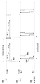
図5に、S306の時点でのカメラ101、制御端末102、AP103のそれぞれが送受信する無線信号のタイミングの例を示す。図5において、カメラ101は、AP103がBeacon Interval毎に送信するビーコンパケット501を受信する。一方、カメラ101は、制御端末102とconnInterval毎にBLEデータパケット502、503を送受信し合う。ここで、802.11ax通信とBLE通信では、それぞれ親局である制御端末102とAP103が独自に通信タイミングを決定している。そのため、ビーコンパケット501とBLEデータパケット502、503は同時に送信されることがあり、干渉が発生し得る。干渉が発生していると、カメラ101は、ビーコンパケット501を正常に受信できるまでスキャン状態を継続する必要があり、消費電力の観点から効率が悪い。本実施形態では、このような干渉の発生を回避するために、カメラ101の制御部201は、以下に説明するように、S307以降の処理を行う。
FIG. 5 shows an example of the timing of the radio signals transmitted and received by each of the
すなわち、制御部201は、まず、受信したビーコンパケット501からBeacon Intervalの情報とTWT(TWT1、TWT2)の情報を得て、connIntervalとBeacon Intervalとを比較する。そして、制御部201は、connIntervalとBeacon IntervalのN倍(Nは自然数)との差分が所定値(DImax)を超えるか否かを判定する(S307)。S307でYesの場合、制御部201は、connIntervalがBeacon IntervalのN倍との差分が所定値以下(DImax以下)となるようなconnIntervalを決定する。続いて、BLE通信部206は、制御端末102に対して、制御部201により決定されたconnIntervalでconnIntervaの変更要求を行う(S308)。すなわち、S307とS308の処理では、connIntervalとBeacon Interval×Nとが略等しくなるように、制御部201が動作する。
That is, the
ここで、S307とS308の処理を、より具体な例を用いて説明する。BLE規格では、connIntervalは、7.5ms以上4s以下かつ1.25msの整数倍の値であることが定められている。一方、802.11規格では、Beacon Intervalは1.024msの整数倍の値であることが定められている。例えば、一つの例において、connInterval=30ms(1.25ms×24)、Beacon Interval=102.4ms(1.024ms×100)、DImax=500μs、N=1とする。この場合、S307では、connIntervalがBeacon IntervalのN倍の差分は72.4msとなるため、処理はS308に進む。そして、S308では、制御部201は、connIntervalがBeacon IntervalのN倍との差分がDImax以下となるように、connInterval=102.5ms(1.25ms×82)と決定する。これを受けて、BLE通信部206は、制御端末102に対して、決定したconnInterval=102.5msでconnInterval変更要求を行う。
Here, the processing of S307 and S308 will be described with reference to more specific examples. The BLE standard stipulates that connInterval is a value of 7.5 ms or more and 4 s or less and an integral multiple of 1.25 ms. On the other hand, the 802.11 standard stipulates that Beacon Interval is a value that is an integral multiple of 1.024 ms. For example, in one example, connInterval = 30 ms (1.25 ms × 24), Beacon Interval = 102.4 ms (1.024 ms × 100), DImax = 500 μs, N = 1. In this case, in S307, the difference of N times that of Beacon Interval is 72.4 ms, so that the process proceeds to S308. Then, in S308, the
BLE規格では、connInterval変更要求は、接続パラメータ要求パケット(LL_CONNECTION_PARAM_REQ)を使用して行うことが可能である。より詳細には、BLE通信部206は、Interval_MinフィールドとInterval_Maxフィールドを82(0x52)と設定されたLL_CONNECTION_PARAM_REQを、BLE親局である制御端末102に送信する。
In the BLE standard, the connInterval change request can be made by using the connection parameter request packet (LL_CONNECTION_PARAM_CHECK). More specifically, the
制御端末102は、カメラ101から送信されたconnIntervalの変更要求(LL_CONNECTION_PARAM_REQ)を受信する。続いて、制御端末102は、接続更新要求パケット(LL_CONNECTION_UPDATE_REQ)で応答する。
The
正常に接続パラメータ要求パケット(LL_CONNECTION_PARAM_REQ)と接続更新要求パケット(LL_CONNECTION_UPDATE_REQ)の送受信が完了すると、connIntervalが102.5msに変更される。connIntervalは、接続更新要求パケット(LL_CONNECTION_UPDATE_REQ)のInstantフィールドで指定されたタイミングで変更され得る。 When the transmission / reception of the connection parameter request packet (LL_CONMENTION_PARAM_RET) and the connection update request packet (LL_CONNECTION_UPDATE_CHECK) is normally completed, the connInterval is changed to 102.5 ms. The connInterval can be changed at the timing specified in the Instant field of the connection update request packet (LL_CONCEPTION_UPDATE_RET).
図6に、S308の処理が完了した後の、カメラ101、制御端末102、AP103の送受信する無線信号のタイミングの例を示す。図6に示すように、S308の処理が完了した後は、connIntervalとBeacon Intervalが略一致した状態となる。なお、この時点では、BLE通信と無線LAN通信のタイミングはランダムに決定されており、図6は、BLE通信がマルチユーザアップリンク通信(TWT1とTWT2の間)と重なっている様子を示している。
FIG. 6 shows an example of the timing of the radio signals transmitted and received by the
図3に戻り、続くS309では、制御部201は、802.11axのスリープ期間外でBLE通信が行われるか否かを判定する。本実施形態では、制御部201は、802.11axのTWT1により指定されるスリープ期間(図4のSleep407)外でBLE通信が行われるか否かを判定する。BLE通信がスリープ期間外で行われると判定した場合(S309でYes)、制御部201は、BLE通信タイミングがスリープ期間となるように(802.11axの通信タイミング以外の期間に位置するように)BLE通信タイミングを決定する。これを受けて、BLE通信部206は、制御端末102に対して、決定したBLE通信タイミングでのBLE通信タイミング変更要求を行う(S310)。なお、図3の例では、S308とS310の要求は別々に行っているが、併せて行ってもよい。
Returning to FIG. 3, in S309 following, the
BLE通信タイミングの変更要求は、connIntervalと同様に接続パラメータ要求パケット(LL_CONNECTION_PARAM_REQ)を使用することで行われる。接続パラメータ要求パケット(LL_CONNECTION_PARAM_REQ)のOffsetフィールドでタイミングの変更を1.25msの自然数倍で指定することが可能である。 The BLE communication timing change request is made by using the connection parameter request packet (LL_CONNECTION_PARAM_CHECK) as in the case of connInterval. It is possible to specify the timing change in the Offset field of the connection parameter request packet (LL_CONNECTION_PARAM_CHECK) by a natural number multiple of 1.25 ms.
制御端末102は、接続パラメータ要求パケット(LL_CONNECTION_PARAM_REQ)を受信すると、これに対して接続更新要求パケット(LL_CONNECTION_UPDATE_REQ)で応答する。これにより、BLE通信タイミングが変更される。
When the
図7にS310の処理が完了した後の、カメラ101、制御端末102、AP103の送受信する無線信号のタイミングの例を示す。図7に示すように、カメラ101と制御端末102は、TWT1により指定されるスリープ期間内でBLE通信が行われる状態となる。なお、上述した例では、Beacon Interval=102.4msに対して、connInterval=102.5msであるため、次第にBLE通信タイミングがスリープ期間外にずれていくこととなる。このため、カメラ101は、以降の処理では、802.11ax通信処理(S314〜S316)が完了するまで、802.11ax通信処理とBLE通信タイミング調整処理(S311〜S312)を並列に実行する。なお、BLE通信タイミング調整処理(S311〜S312)は、S309〜S310と同じ処理であるため、その説明は省略する。
FIG. 7 shows an example of the timing of the radio signals transmitted and received by the
S314では、制御部201は、無線LAN通信部205に対して、AP103との無線LAN接続を確立するよう指示する。この指示に応じて、無線LAN通信部205は、AP103との無線LAN接続処理を行う。無線LAN接続確立後、制御部201は、無線LAN通信部205に対して、AP103にマルチユーザアップリンク通信を使用して画像データを送信するよう指示する。この指示に応じて、無線LAN通信部205は、画像データをAP103に送信する(アップロードする)(S315)。そして、画像データのアップロードが完了すると、制御部201は、無線LAN通信部205への電源供給を停止する(S316)。
In S314, the
このように、本実施形態では、無線LAN子局かつBLE子局として動作するカメラ101が、802.11axのスリープ期間にBLE通信が行われるよう、BLE親局に要求する。これにより、BLE通信と802.11ax通信との干渉を防ぐことができる。なお、本実施形態では、当該BLE親局への要求は、BLE通信周期と通信タイミングに関するパラメータの変更要求に対応するが、802.11axのスリープ期間にBLE通信を行うための要求であれば、他のパラメータ変更要求であってもよい。
As described above, in the present embodiment, the
また、本実施形態では、カメラ101は、制御端末102に対して、802.11axのTWT1により指定されるスリープ期間(図4のSleep407)にBLE通信を行うための要求を行った。他の形態として、他のスリープ期間(図4のSleep408、409)にBLE通信を行うための要求を行うように構成してもよい。
Further, in the present embodiment, the
また、本実施形態では、カメラ101は無線LAN子局かつBLE子局として動作するものとしたが、無線LAN親局かつBLE子局として動作する場合においても、本実施形態は同様に適用可能である。この場合、カメラ101は、ビーコンパケット受信を行うS306は不要であり、自身の送信するビーコンパケットに基づいてS307〜S315の処理を行うことで、802.11axのスリープ期間にBLE通信を行うよう動作する。
Further, in the present embodiment, the
また、本実施形態では、無線通信方式として、無線LANとして802.11axを用いるものとして説明したが、本実施形態はこれに限定されるものではない。PCF(Point Coordination Function)等、スケジューリングが行われる無線LAN通信であれば、無線LAN通信期間外にBLE通信タイミングを調整することで、本実施形態と同様に効果を得ることができる。 Further, in the present embodiment, it has been described that 802.11ax is used as the wireless LAN as the wireless communication method, but the present embodiment is not limited to this. In the case of wireless LAN communication such as PCF (Point Coordination Foundation) in which scheduling is performed, the same effect as in the present embodiment can be obtained by adjusting the BLE communication timing outside the wireless LAN communication period.
<実施形態2>
実施形態1では、無線LAN子局かつBLE子局として動作するカメラ101が、BLE親局に接続パラメータとして、BLE通信周期とBLE通信タイミングの変更を要求した。実施形態2として、親局と子局の役割を変更するよう要求する実施形態を説明する。すなわち、本実施形態では、カメラ101がBLE親局、制御端末102がBLE子局として動作するよう役割を変更し、BLE親局となったカメラ101がBLE通信周期とBLE通信タイミングを変更する。以下、実施形態1と異なる点について説明し、共通の事項は説明を省略する。
<Embodiment 2>
In the first embodiment, the
本実施形態における役割変更の処理の流れを示すシーケンスチャートを図8に示す。図8のシーケンスチャートにおいて、初期状態ではカメラ101はBLE子局、制御端末102はBLE親局として動作しているものとする。この初期状態において、カメラ101は、制御端末102から画像データアップロード指示を受信する(S801)と、制御端末102に役割変更要求を送信する(S802)。制御端末102は、役割変更要求を受信すると、BLEデータパケットの送信を停止し(S803)、ADV_INDの送信を開始する(S804)。一方、カメラ101は制御端末102のBLEデータパケット送信が停止したことを検出すると(S805)、アドバタイズスキャン状態へと遷移する(S806)。そして、カメラ101は制御端末102の送信するADV_INDに対してCONNECT_REQを送信することで、カメラ101をBLE親局、制御端末102をBLE子局としたBLE接続が確立される(S807)。
FIG. 8 shows a sequence chart showing the flow of the role change process in the present embodiment. In the sequence chart of FIG. 8, it is assumed that the
カメラ101はBLE親局となった後、実施形態1と同様に、802.11axの通信期間外であるスリープ期間にBLE通信が行われるようBLE通信周期とBLE通信タイミングを変更する。この変更は、BLE規格に準拠して行う。具体的には、まずカメラ101は、接続パラメータ要求パケット(LL_CONNECTION_PARAM_REQ)を送信する。そして、制御端末102は、接続パラメータ要求パケット(LL_CONNECTION_PARAM_REQ)の内容を確認した後、接続パラメータ応答パケット(LL_CONNECTION_PARAM_RSP)を送信する。カメラ101は、接続パラメータ応答パケット(LL_CONNECTION_PARAM_RSP)に対して接続更新要求パケット(LL_CONNECTION_UPDATE_REQ)を送信することで、BLE通信周期とBLE通信タイミングを変更可能である。
After becoming the BLE master station, the
このように、以上に説明した実施形態によれば、BLE親局となったカメラ101がマルチユーザアップリンク通信期間外であるスリープ期間にBLE通信が行われるようにBLE通信周期とBLE通信タイミングを変更する。これにより、BLE通信とマルチユーザアップリンク通信との干渉を防ぐことが可能となる。
As described above, according to the embodiment described above, the BLE communication cycle and the BLE communication timing are set so that the
なお、上述の各実施形態ではIEEE802.11axとBLEの通信を例に説明したが、同一の周波数帯を用いる任意の複数の無線通信に適用可能である。例えば、その他のIEEE802.11シリーズやBluetooth(例えばバージョン4.0以外のバージョンのBluetooth)の通信にも適用可能である。ここで、同一の周波数帯とは、周波数の値が完全に一致するものに限定されるのではなく、周波数帯域の少なくとも一部が重なるものや、通信エラーを引き起こす干渉が発生する程度に近接した周波数帯を含むものである。 In each of the above embodiments, the communication between IEEE802.11ax and BLE has been described as an example, but it can be applied to any plurality of wireless communications using the same frequency band. For example, it can be applied to communication of other 802.11 series and Bluetooth (for example, a version other than version 4.0 of Bluetooth). Here, the same frequency band is not limited to those in which the frequency values are exactly the same, but is close to those in which at least a part of the frequency bands overlap or interference that causes a communication error occurs. It includes frequency bands.
また、上述の各実施形態におけるカメラ101は通信装置の一例であり、スマートフォンやPC、プリンタ、ディスプレイ等のその他の装置であってもよい。
Further, the
<その他の実施形態>
本発明は、上述の実施形態の1以上の機能を実現するプログラムを、ネットワーク又は記憶媒体を介してシステム又は装置に供給し、そのシステム又は装置のコンピュータにおける1つ以上のプロセッサーがプログラムを読出し実行する処理でも実現可能である。また、1以上の機能を実現する回路(例えば、ASIC)によっても実現可能である。
<Other embodiments>
The present invention supplies a program that realizes one or more functions of the above-described embodiment to a system or device via a network or storage medium, and one or more processors in the computer of the system or device reads and executes the program. It can also be realized by the processing to be performed. It can also be realized by a circuit (for example, ASIC) that realizes one or more functions.
101 カメラ、102 制御端末、103 AP、104 サーバ 101 camera, 102 control terminal, 103 AP, 104 server
Claims (12)
第1の他の装置との間で、前記第1の他の装置により指定された第1の周期で第1の無線通信方式を用いて通信を行う第1の通信手段と、
第2の他の装置との間で、前記第1の無線通信方式で用いる周波数帯と同一の周波数帯を用いる第2の無線通信方式を用いて通信を行う第2の通信手段と、有し、
前記第1の通信手段による通信タイミングと前記第2の通信手段による通信タイミングが重なる場合に、前記第1の通信手段は、前記第1の通信手段による通信タイミングと前記第2の通信手段による通信タイミングが重ならないよう要求するための信号を前記第1の他の装置に送信することを特徴とする通信装置。 It ’s a communication device,
A first communication means for communicating with the first other device using the first wireless communication method in the first cycle designated by the first other device.
It has a second communication means for communicating with the second other device by using the second wireless communication method using the same frequency band as the frequency band used in the first wireless communication method. ,
When the communication timing by the first communication means and the communication timing by the second communication means overlap, the first communication means communicates with the communication timing by the first communication means and the communication by the second communication means. A communication device comprising transmitting a signal for requesting that the timings do not overlap to the first other device.
前記差が前記所定値より大きい場合に、前記差が前記所定値以下となるように、前記第1の周期を決定する決定手段を更に有し、
前記第1の通信手段は、前記決定手段により決定された周期に前記第1の周期を変更することを要求するための信号を前記第1の他の装置に送信することを特徴とする請求項1に記載の通信装置。 Determining whether or not the difference between the first cycle and the natural number multiple of the second cycle, which is the cycle of a predetermined signal periodically communicated by the second communication means, is larger than the predetermined value. Means and
If the difference is greater than the predetermined value, so that the difference is equal to or less than the predetermined value, further comprising a decision means that determine the first period,
The first communication means is characterized in that a signal for requesting that the first cycle is changed to the cycle determined by the determination means is transmitted to the first other device. The communication device according to 1.
前記差が前記所定値より大きい場合に、前記差が前記所定値以下となるように、前記第1の周期を決定する決定手段を更に有し、
前記第1の通信手段は、前記決定手段により決定された周期に前記第1の周期を変更することを要求するための信号を前記第1の他の装置に送信することを特徴とする請求項6に記載の通信装置。 A determination means for determining whether or not the difference between the first cycle and the natural number multiple of the second cycle, which is the cycle of the beacon packet periodically communicated by the second communication means, is larger than a predetermined value. When,
If the difference is greater than the predetermined value, so that the difference is equal to or less than the predetermined value, further comprising a decision means that determine the first period,
The first communication means is characterized in that a signal for requesting that the first cycle is changed to the cycle determined by the determination means is transmitted to the first other device. The communication device according to 6.
第2の他の装置との間で、前記第1の無線通信方式で用いる周波数帯と同一の周波数帯を用いる第2の無線通信方式を用いて通信を行う第2の通信手段と、
を有する通信装置の制御方法であって、
前記第1の通信手段による通信タイミングと前記第2の通信手段による通信タイミングが重なる場合に、前記第1の通信手段に、前記第1の通信手段による通信タイミングと前記第2の通信手段による通信タイミングが重ならないよう要求するための信号を前記第1の他の装置に送信させる制御工程を有することを特徴とする通信装置の制御方法。 A first communication means for communicating with the first other device using the first wireless communication method in the first cycle designated by the first other device.
A second communication means for communicating with the second other device by using the second wireless communication method using the same frequency band as the frequency band used in the first wireless communication method.
It is a control method of a communication device having
When the communication timing by the first communication means and the communication timing by the second communication means overlap, the communication timing by the first communication means and the communication by the second communication means are combined with the first communication means. A method for controlling a communication device, which comprises a control step of causing the first other device to transmit a signal for requesting that the timings do not overlap.
Priority Applications (1)
| Application Number | Priority Date | Filing Date | Title |
|---|---|---|---|
| JP2017151755A JP6971695B2 (en) | 2017-08-04 | 2017-08-04 | Communication equipment, control methods for communication equipment, and programs |
Applications Claiming Priority (1)
| Application Number | Priority Date | Filing Date | Title |
|---|---|---|---|
| JP2017151755A JP6971695B2 (en) | 2017-08-04 | 2017-08-04 | Communication equipment, control methods for communication equipment, and programs |
Publications (3)
| Publication Number | Publication Date |
|---|---|
| JP2019033321A JP2019033321A (en) | 2019-02-28 |
| JP2019033321A5 JP2019033321A5 (en) | 2020-08-13 |
| JP6971695B2 true JP6971695B2 (en) | 2021-11-24 |
Family
ID=65523698
Family Applications (1)
| Application Number | Title | Priority Date | Filing Date |
|---|---|---|---|
| JP2017151755A Active JP6971695B2 (en) | 2017-08-04 | 2017-08-04 | Communication equipment, control methods for communication equipment, and programs |
Country Status (1)
| Country | Link |
|---|---|
| JP (1) | JP6971695B2 (en) |
Families Citing this family (2)
| Publication number | Priority date | Publication date | Assignee | Title |
|---|---|---|---|---|
| JP2023028721A (en) * | 2021-08-20 | 2023-03-03 | セイコーグループ株式会社 | Transmission device, communication system, transmission method, and program |
| WO2023218867A1 (en) * | 2022-05-10 | 2023-11-16 | ソニーセミコンダクタソリューションズ株式会社 | Communication device and communication system |
Family Cites Families (3)
| Publication number | Priority date | Publication date | Assignee | Title |
|---|---|---|---|---|
| JP2005045368A (en) * | 2003-07-23 | 2005-02-17 | Canon Inc | Wireless communication apparatus and control method of wireless communication |
| US8160001B2 (en) * | 2006-05-25 | 2012-04-17 | Altair Semiconductor Ltd. | Multi-function wireless terminal |
| JP6262699B2 (en) * | 2015-09-30 | 2018-01-17 | 京セラ株式会社 | Wireless communication device and processor |
-
2017
- 2017-08-04 JP JP2017151755A patent/JP6971695B2/en active Active
Also Published As
| Publication number | Publication date |
|---|---|
| JP2019033321A (en) | 2019-02-28 |
Similar Documents
| Publication | Publication Date | Title |
|---|---|---|
| US10219224B2 (en) | WLAN system with opportunistic transitioning to a low power state for power management | |
| EP3089525B1 (en) | Implicit power management mode and state transitions | |
| CN107113731B (en) | Power-efficient channel access for wireless devices in dense wireless networks | |
| TWI526030B (en) | Tune back coordination with connected mode discontinuous receive | |
| CN102308657B (en) | Optimization of uplink resource grant procedure | |
| US10470238B2 (en) | Power saving for tight coupled interworking | |
| US20050254459A1 (en) | Aggregation scheduler | |
| US8711746B2 (en) | Method, apparatus or computer program for changing from scheduled to unscheduled communication modes | |
| KR20180043265A (en) | Back-off mechanism technologies for space reuse | |
| WO2012145905A1 (en) | Method for controlling working state and terminal equipment | |
| CN113812190A (en) | Framework and method for dynamic channel selection for IEEE 802.15.4z | |
| JP2021170840A (en) | Communication device, control method, and program | |
| JP2021170840A5 (en) | ||
| JP6971695B2 (en) | Communication equipment, control methods for communication equipment, and programs | |
| US20180160459A1 (en) | Method and apparatus for cooperative microsleep operation | |
| KR20210015101A (en) | Electronic device for providing dual connectivy and method for operating thereof | |
| US20150271801A1 (en) | Wireless communication apparatus and method, wireless terminal, memory card, and integrated circuit | |
| JP2020178315A (en) | Communication apparatus, method of controlling communication apparatus, and program | |
| CN114302498A (en) | Apparatus and method for multi-link operation through access point with simultaneous transmit-receive constraints | |
| JP7370696B2 (en) | Communication device, control method, and program | |
| JP2020078003A (en) | Communication device, control method, and program | |
| WO2022068752A1 (en) | Communication resource activation method, terminal, and network-side device | |
| US20240107444A1 (en) | Base station discontinuous reception and transmission design for energy saving network | |
| US11477680B2 (en) | Electronic device and cellular communication quality measurement interval adjustment method thereof | |
| US20230239923A1 (en) | Resource transmission method, terminal device, and network device |
Legal Events
| Date | Code | Title | Description |
|---|---|---|---|
| A521 | Request for written amendment filed |
Free format text: JAPANESE INTERMEDIATE CODE: A523 Effective date: 20200706 |
|
| A621 | Written request for application examination |
Free format text: JAPANESE INTERMEDIATE CODE: A621 Effective date: 20200706 |
|
| RD01 | Notification of change of attorney |
Free format text: JAPANESE INTERMEDIATE CODE: A7421 Effective date: 20210103 |
|
| A521 | Request for written amendment filed |
Free format text: JAPANESE INTERMEDIATE CODE: A523 Effective date: 20210113 |
|
| A977 | Report on retrieval |
Free format text: JAPANESE INTERMEDIATE CODE: A971007 Effective date: 20210810 |
|
| A131 | Notification of reasons for refusal |
Free format text: JAPANESE INTERMEDIATE CODE: A131 Effective date: 20210813 |
|
| A521 | Request for written amendment filed |
Free format text: JAPANESE INTERMEDIATE CODE: A523 Effective date: 20210902 |
|
| TRDD | Decision of grant or rejection written | ||
| A01 | Written decision to grant a patent or to grant a registration (utility model) |
Free format text: JAPANESE INTERMEDIATE CODE: A01 Effective date: 20211004 |
|
| A61 | First payment of annual fees (during grant procedure) |
Free format text: JAPANESE INTERMEDIATE CODE: A61 Effective date: 20211102 |
|
| R151 | Written notification of patent or utility model registration |
Ref document number: 6971695 Country of ref document: JP Free format text: JAPANESE INTERMEDIATE CODE: R151 |