JP6971632B2 - Image forming device - Google Patents
Image forming device Download PDFInfo
- Publication number
- JP6971632B2 JP6971632B2 JP2017104005A JP2017104005A JP6971632B2 JP 6971632 B2 JP6971632 B2 JP 6971632B2 JP 2017104005 A JP2017104005 A JP 2017104005A JP 2017104005 A JP2017104005 A JP 2017104005A JP 6971632 B2 JP6971632 B2 JP 6971632B2
- Authority
- JP
- Japan
- Prior art keywords
- image
- toner
- developing
- charging
- image forming
- Prior art date
- Legal status (The legal status is an assumption and is not a legal conclusion. Google has not performed a legal analysis and makes no representation as to the accuracy of the status listed.)
- Active
Links
Images


Classifications
-
- G—PHYSICS
- G03—PHOTOGRAPHY; CINEMATOGRAPHY; ANALOGOUS TECHNIQUES USING WAVES OTHER THAN OPTICAL WAVES; ELECTROGRAPHY; HOLOGRAPHY
- G03G—ELECTROGRAPHY; ELECTROPHOTOGRAPHY; MAGNETOGRAPHY
- G03G15/00—Apparatus for electrographic processes using a charge pattern
- G03G15/02—Apparatus for electrographic processes using a charge pattern for laying down a uniform charge, e.g. for sensitising; Corona discharge devices
- G03G15/0266—Arrangements for controlling the amount of charge
-
- G—PHYSICS
- G03—PHOTOGRAPHY; CINEMATOGRAPHY; ANALOGOUS TECHNIQUES USING WAVES OTHER THAN OPTICAL WAVES; ELECTROGRAPHY; HOLOGRAPHY
- G03G—ELECTROGRAPHY; ELECTROPHOTOGRAPHY; MAGNETOGRAPHY
- G03G15/00—Apparatus for electrographic processes using a charge pattern
- G03G15/02—Apparatus for electrographic processes using a charge pattern for laying down a uniform charge, e.g. for sensitising; Corona discharge devices
- G03G15/0208—Apparatus for electrographic processes using a charge pattern for laying down a uniform charge, e.g. for sensitising; Corona discharge devices by contact, friction or induction, e.g. liquid charging apparatus
- G03G15/0216—Apparatus for electrographic processes using a charge pattern for laying down a uniform charge, e.g. for sensitising; Corona discharge devices by contact, friction or induction, e.g. liquid charging apparatus by bringing a charging member into contact with the member to be charged, e.g. roller, brush chargers
-
- G—PHYSICS
- G03—PHOTOGRAPHY; CINEMATOGRAPHY; ANALOGOUS TECHNIQUES USING WAVES OTHER THAN OPTICAL WAVES; ELECTROGRAPHY; HOLOGRAPHY
- G03G—ELECTROGRAPHY; ELECTROPHOTOGRAPHY; MAGNETOGRAPHY
- G03G21/00—Arrangements not provided for by groups G03G13/00 - G03G19/00, e.g. cleaning, elimination of residual charge
- G03G21/0005—Arrangements not provided for by groups G03G13/00 - G03G19/00, e.g. cleaning, elimination of residual charge for removing solid developer or debris from the electrographic recording medium
- G03G21/0011—Arrangements not provided for by groups G03G13/00 - G03G19/00, e.g. cleaning, elimination of residual charge for removing solid developer or debris from the electrographic recording medium using a blade; Details of cleaning blades, e.g. blade shape, layer forming
-
- G—PHYSICS
- G03—PHOTOGRAPHY; CINEMATOGRAPHY; ANALOGOUS TECHNIQUES USING WAVES OTHER THAN OPTICAL WAVES; ELECTROGRAPHY; HOLOGRAPHY
- G03G—ELECTROGRAPHY; ELECTROPHOTOGRAPHY; MAGNETOGRAPHY
- G03G21/00—Arrangements not provided for by groups G03G13/00 - G03G19/00, e.g. cleaning, elimination of residual charge
- G03G21/16—Mechanical means for facilitating the maintenance of the apparatus, e.g. modular arrangements
- G03G21/1661—Mechanical means for facilitating the maintenance of the apparatus, e.g. modular arrangements means for handling parts of the apparatus in the apparatus
- G03G21/169—Mechanical means for facilitating the maintenance of the apparatus, e.g. modular arrangements means for handling parts of the apparatus in the apparatus for the cleaning unit
-
- G—PHYSICS
- G03—PHOTOGRAPHY; CINEMATOGRAPHY; ANALOGOUS TECHNIQUES USING WAVES OTHER THAN OPTICAL WAVES; ELECTROGRAPHY; HOLOGRAPHY
- G03G—ELECTROGRAPHY; ELECTROPHOTOGRAPHY; MAGNETOGRAPHY
- G03G2215/00—Apparatus for electrophotographic processes
- G03G2215/02—Arrangements for laying down a uniform charge
- G03G2215/021—Arrangements for laying down a uniform charge by contact, friction or induction
Description
本発明は、電子写真方式や静電記録方式を用いた複写機、プリンター、ファクシミリ装置などの画像形成装置に関するものである。 The present invention relates to an image forming apparatus such as a copier, a printer, and a facsimile machine using an electrophotographic method or an electrostatic recording method.
電子写真方式などを用いた画像形成装置では、像担持体から転写残トナーやジャム(記録材の詰まり)が発生した場合の未転写トナーなどを除去する方式として、像担持体に当接させて配置したクリーニング部材によって物理的に掻き取る方式がある。クリーニング部材としては、ウレタンゴムなどの弾性材料で形成されたクリーニングブレードが広く用いられ、このクリーニングブレードは、自由端部が像担持体の回転方向の上流側を向くカウンター方向で像担持体に当接させられる。 In an image forming apparatus using an electrophotographic method or the like, as a method of removing residual transfer toner and untransferred toner when jam (clogging of recording material) occurs from the image carrier, the image carrier is brought into contact with the image carrier. There is a method of physically scraping with the arranged cleaning member. As a cleaning member, a cleaning blade made of an elastic material such as urethane rubber is widely used, and this cleaning blade hits the image carrier in a counter direction in which the free end faces the upstream side in the rotation direction of the image carrier. Be touched.
クリーニングブレードを用いる場合、像担持体へのトナーの供給が少ない状態で像担持体を回転させ続けると、像担持体とクリーニングブレードとの間の摩擦力が上昇する。これにより、微視的にクリーニングブレードがびびり(振動)を起こして、クリーニング不良が発生することがある。クリーニング不良は、トナーがクリーニングブレードによって掻き取られずにクリーニングブレードをすり抜けてしまう現象(以下、単に「すり抜け」ともいう。)である。像担持体へのトナーの供給が少ない状態で像担持体が回転する状況としては、低印字率の画像の印字が続く場合や、予備回転(画像形成工程の前後の前回転工程、後回転工程など)が行われる場合などが挙げられる。 When the cleaning blade is used, if the image carrier is continuously rotated while the toner supply to the image carrier is small, the frictional force between the image carrier and the cleaning blade increases. As a result, the cleaning blade may microscopically cause chatter (vibration), resulting in poor cleaning. Cleaning failure is a phenomenon in which toner is not scraped off by the cleaning blade and slips through the cleaning blade (hereinafter, also simply referred to as “passing through”). The situation in which the image carrier rotates while the toner supply to the image carrier is small is that the image with a low printing rate continues to be printed, or the preliminary rotation (pre-rotation step before and after the image forming step, back rotation step). Etc.) is performed.
これに対し、非画像形成時に像担持体とクリーニングブレードとの当接部にトナーを供給する供給動作を行うことで、トナーや外添剤による潤滑効果によって摩擦力を低減し、クリーニングブレードのびびりに起因するクリーニング不良を抑制する方法がある。特許文献1は、環境や印字率に応じて、供給動作におけるトナーの供給量や供給動作を実行する頻度を制御することを開示している。従来は、供給動作において、像担持体に所定の印字パターン(ベタ黒や細線)を形成し、この印字パターンのトナーを像担持体とクリーニングブレードとの当接部に供給している。
On the other hand, by performing a supply operation of supplying toner to the contact portion between the image carrier and the cleaning blade during non-image formation, the frictional force is reduced by the lubrication effect of the toner and the external additive, and the cleaning blade chatters. There is a method of suppressing cleaning defects caused by.
また、電子写真方式などを用いた画像形成装置では、像担持体を帯電させる方式として、像担持体に接触又は近接させて配置した帯電部材に帯電バイアスを印加することで像担持体を帯電させる方式がある。また、この帯電部材を用いた方式には、帯電バイアスとして直流電圧と交流電圧とが重畳された振動電圧を帯電部材に印加するAC帯電方式がある。AC帯電方式は、AC放電による電位均し効果により帯電後の像担持体の表面電位の均一性が優れているという利点を有する。一方、AC帯電方式は、像担持体と帯電部材との間での放電による像担持体の表面の削れや放電生成物の発生量が比較的大きい。特許文献2は、非画像形成時に帯電部材に放電開始電圧以下のピーク間電圧値の交流電圧を印加することで、放電生成物の発生を抑えながらクリーニング不良を抑制する方法を開示している。
Further, in an image forming apparatus using an electrophotographic method or the like, as a method of charging an image carrier, the image carrier is charged by applying a charging bias to a charging member arranged in contact with or close to the image carrier. There is a method. Further, as a method using this charging member, there is an AC charging method in which a vibration voltage in which a DC voltage and an AC voltage are superimposed is applied to the charging member as a charging bias. The AC charging method has an advantage that the uniformity of the surface potential of the image carrier after charging is excellent due to the potential leveling effect of AC discharge. On the other hand, in the AC charging method, the amount of scraping of the surface of the image carrier due to the discharge between the image carrier and the charging member and the amount of discharge products generated are relatively large.
しかしながら、従来のように供給動作において通常の印字パターン(ベタ黒や細線)を像担持体に形成すると、その印字パターンのトナー自体のすり抜けによりクリーニング不良が発生することがある。これは、印字パターンを構成するトナーは十分な電荷を保持しているものが多く、その高い鏡映力のためにクリーニングブレードによって掻き取られにくいことが原因の一つである。そして、この印字パターンのトナーによるクリーニング不良は、AC帯電方式を用いる場合に顕著になる傾向がある。これは、AC帯電方式を用いる場合、電気的な振動が物理的な振動として像担持体へ伝播することで、クリーニングブレードによるクリーニング性が低下することが原因であると考えられる。 However, when a normal print pattern (solid black or thin line) is formed on the image carrier in the supply operation as in the conventional case, cleaning failure may occur due to the slipping of the toner itself of the print pattern. One of the reasons for this is that many of the toners constituting the print pattern retain a sufficient charge and are difficult to be scraped off by the cleaning blade due to their high reflection power. Then, the cleaning defect due to the toner of this print pattern tends to become remarkable when the AC charging method is used. It is considered that this is because when the AC charging method is used, the electrical vibration propagates to the image carrier as physical vibration, so that the cleaning property by the cleaning blade is deteriorated.
したがって、本発明の目的は、AC帯電方式を用いる場合に、非画像形成時に像担持体とクリーニング部材との当接部に十分にトナーを供給できると共に、そのトナーによるクリーニング不良の発生を抑制することのできる画像形成装置を提供することである。 Therefore, an object of the present invention is that when the AC charging method is used, toner can be sufficiently supplied to the contact portion between the image carrier and the cleaning member at the time of non-image formation, and the occurrence of cleaning defects due to the toner is suppressed. It is to provide an image forming apparatus capable of this.
上記目的は本発明に係る画像形成装置にて達成される。要約すれば、本発明は、トナー像を担持する回転可能な像担持体と、前記像担持体の表面を帯電させる帯電部材と、直流成分と交流成分とが重畳された帯電電圧を前記帯電部材に印加する帯電電源と、帯電した前記像担持体上に静電像を形成する静電像形成手段と、前記像担持体上に形成された前記静電像にトナーを供給して前記トナー像を形成する現像部材と、現像電圧を前記現像部材に印加する現像電源と、前記像担持体上に形成された前記トナー像を転写位置で被転写体に転写させる転写手段と、前記像担持体の回転方向において前記転写位置より下流側かつ前記帯電部材との当接位置より上流側で前記像担持体に当接し、前記像担持体上から前記トナーを除去するクリーニング部材と、非画像形成時に、前記トナーを前記クリーニング部材に供給する供給動作を実行するために、前記トナーを移動させるための前記帯電電圧、前記現像電圧をそれぞれ前記帯電部材と前記現像部材に印加させることが可能な制御部と、を有し、前記供給動作の実行時に印加する前記帯電電圧の前記交流成分のピーク間電圧をVpp1(V)とすると、画像形成時に印加する前記帯電電圧の前記交流成分のピーク間電圧は、前記Vpp1(V)より大きく、前記像担持体と前記帯電部材との間の前記直流成分の放電開始電圧をVth(V)とすると、前記制御部は、前記供給動作を実行するために、次式、2Vth(V)≦Vpp1(V)≦(2Vth+200)(V)を満たす前記Vpp1(V)を前記帯電部材に印加するように制御を行い、かつ、前記制御部は、前記非画像形成時に、前記帯電電圧の前記交流成分のピーク間電圧の切り替えを行うことが可能であり、前記画像形成時に印加する前記帯電電圧の前記交流成分のピーク間電圧をVpp2(V)、前記帯電部材に前記Vpp1(V)が印加され電位が形成される前記像担持体上の領域とは別の前記像担持体上の領域が、前記帯電部材との当接位置を通過する際の前記帯電電圧の前記交流成分のピーク間電圧をVpp3(V)としたとき、次式、Vpp1(V)<Vpp3(V)<Vpp2(V)を満たすように前記切り替えの制御を行うことを特徴とする画像形成装置である。 The above object is achieved by the image forming apparatus according to the present invention. In summary, the present invention applies a chargeable voltage in which a rotatable image carrier that carries a toner image, a charging member that charges the surface of the image carrier, and a DC component and an AC component are superimposed. A charged power supply applied to the image carrier, an electrostatic image forming means for forming an electrostatic image on the charged image carrier, and a toner image supplied to the electrostatic image formed on the image carrier. A developing member forming the A cleaning member that abuts on the image carrier and removes the toner from the image carrier on the downstream side of the transfer position and upstream of the contact position with the charging member in the rotational direction of the image carrier, and at the time of non-image formation. A control unit capable of applying the charging voltage and the developing voltage for moving the toner to the charging member and the developing member, respectively, in order to execute a supply operation of supplying the toner to the cleaning member. When the peak voltage of the AC component of the charging voltage applied at the time of executing the supply operation is Vpp1 (V), the peak voltage of the AC component of the charging voltage applied at the time of image formation is When the discharge start voltage of the DC component between the image carrier and the charging member is Vth (V), which is larger than Vpp1 (V), the control unit performs the supply operation. following equation, have a row control to apply 2Vth the (V) ≦ Vpp1 (V) ≦ (2Vth + 200) wherein satisfy (V) Vpp1 (V) to the charging member, and the control unit, the non-image At the time of formation, it is possible to switch the peak-to-peak voltage of the AC component of the charging voltage, and the peak-to-peak voltage of the AC component of the charging voltage applied at the time of image formation is Vpp2 (V), and the charging member. When a region on the image carrier different from the region on the image carrier on which the Vpp1 (V) is applied and a potential is formed passes through the contact position with the charging member, the charging voltage When the peak voltage of the AC component is Vpp3 (V), the switching is controlled so as to satisfy the following equation, Vpp1 (V) <Vpp3 (V) <Vpp2 (V). It is a forming device.
本発明の他の態様によると、トナー像を担持する回転可能な像担持体と、前記像担持体の表面を帯電させる帯電部材と、直流成分と交流成分とが重畳された帯電電圧を前記帯電部材に印加する帯電電源と、帯電した前記像担持体上に静電像を形成する静電像形成手段と、前記像担持体上に形成された前記静電像にトナーを供給して前記トナー像を形成する現像部材と、少なくとも直流成分を含む現像電圧を前記現像部材に印加する現像電源と、前記像担持体上に形成された前記トナー像を転写位置で被転写体に転写させる転写手段と、前記像担持体の回転方向において前記転写位置より下流側かつ前記帯電部材との当接位置より上流側で前記像担持体に当接し、前記像担持体上から前記トナーを除去するクリーニング部材と、非画像形成時に、前記トナーを前記クリーニング部材に供給する供給動作を実行するために、前記現像部材から前記像担持体上に前記トナーを移動させるための前記帯電電圧、前記現像電圧をそれぞれ前記帯電部材と前記現像部材に印加させることが可能な制御部と、を有し、前記供給動作の実行時に印加する前記帯電電圧の前記直流成分をVdc1(V)、画像形成時に印加する前記帯電電圧の前記直流成分をVdc2(V)、前記供給動作の実行時に印加する前記現像電圧の前記直流成分をVdev1(V)、前記画像形成時に印加する前記現像電圧の前記直流成分をVdev2(V)とすると、前記制御部は、次式、0(V)<|Vdc1−Vdev1|(V)<|Vdc2−Vdev2|(V)を満たす前記帯電電圧、前記現像電圧を、それぞれ前記帯電部材、前記現像部材に印加する前記供給動作を実行するように制御を行い、かつ、前記制御部は、前記非画像形成時に、前記帯電電圧の前記直流成分と前記現像電圧の前記直流成分との差分の切り替えを行うことが可能であり、前記帯電部材に前記Vdc1(V)が印加され電位が形成される前記像担持体上の領域とは別の前記像担持体上の領域が、前記帯電部材との当接位置を通過する際に前記帯電部材に印加される前記帯電電圧の前記直流成分をVdc3(V)、前記別の前記像担持体上の領域が前記現像部材との当接位置を通過する際に前記現像部材に印加される前記現像電圧の前記直流成分をVdev3(V)としたとき、次式、|Vdc1−Vdev1|(V)<|Vdc3−Vdev3|(V)<|Vdc2−Vdev2|(V)を満たすように前記切り替えの制御を行うことを特徴とする画像形成装置が提供される。 According to another aspect of the present invention, the chargeable voltage obtained by superimposing a rotatable image carrier that carries a toner image, a charging member that charges the surface of the image carrier, and a DC component and an AC component is charged. The toner is supplied to the charged power supply applied to the member, the electrostatic image forming means for forming an electrostatic image on the charged image carrier, and the electrostatic image formed on the image carrier. A developing member that forms an image, a developing power source that applies a developing voltage containing at least a DC component to the developing member, and a transfer means that transfers the toner image formed on the image carrier to the transferred object at a transfer position. A cleaning member that abuts on the image carrier on the downstream side of the transfer position and upstream of the contact position with the charging member in the rotation direction of the image carrier and removes the toner from the image carrier. And the charging voltage and the developing voltage for moving the toner from the developing member onto the image carrier in order to execute the supply operation of supplying the toner to the cleaning member at the time of non-image formation, respectively. It has a charging member and a control unit that can be applied to the developing member, and the DC component of the charging voltage applied at the time of executing the supply operation is Vdc1 (V), and the charging is applied at the time of image formation. The DC component of the voltage is Vdc2 (V), the DC component of the development voltage applied at the time of executing the supply operation is Vdev1 (V), and the DC component of the development voltage applied at the time of image formation is Vdev2 (V). Then, the control unit uses the charging voltage and the developing voltage that satisfy the following equations, 0 (V) << Vdc1-Vdev1 | (V) << Vdc2-Vdev2 | (V), respectively. There line control so as to perform the feed operation to be applied to the developing member, and said control unit is configured during non-image formation, the difference between the DC component of the DC component and the developing voltage of the charging voltage Switching is possible, and a region on the image carrier different from the region on the image carrier on which the Vdc1 (V) is applied to the charging member to form a potential is the charging member. The DC component of the charging voltage applied to the charging member when passing through the contact position of Vdc3 (V), and the region on the other image carrier passes through the contact position with the developing member. When the DC component of the development voltage applied to the development member is Vdev3 (V), the following equation: | Vdc1-Vdev1 | (V) << | Vdc3-Vdev3 | (V) << | Vdc2- Vdev2 | An image forming apparatus is provided, which controls the switching so as to satisfy (V).
本発明によれば、AC帯電方式を用いる場合に、非画像形成時に像担持体とクリーニング部材との当接部に十分にトナーを供給できると共に、そのトナーによるクリーニング不良の発生を抑制することができる。 According to the present invention, when the AC charging method is used, it is possible to sufficiently supply toner to the contact portion between the image carrier and the cleaning member at the time of non-image formation, and it is possible to suppress the occurrence of cleaning defects due to the toner. can.
以下、本発明に係る画像形成装置を図面に則して更に詳しく説明する。 Hereinafter, the image forming apparatus according to the present invention will be described in more detail with reference to the drawings.
[実施例1]
1.画像形成装置の全体的な構成及び動作
図1は、本実施例の画像形成装置100の概略断面図である。本実施例の画像形成装置100は、電子写真方式を用いたレーザービームプリンターである。
[Example 1]
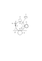
1. 1. Overall Configuration and Operation of the Image Forming Device FIG. 1 is a schematic cross-sectional view of the
画像形成装置100は、トナー像を担持する像担持体としての、回転可能なドラム型の電子写真感光体(感光体)である感光ドラム1を有する。回転体である感光ドラム1は、駆動手段としての駆動モータM1(図3)によって図中矢印R1方向に回転駆動される。回転する感光ドラム1の表面は、帯電手段としてのローラ型の帯電部材である帯電ローラ2によって、所定の極性(本実施例では負極性)の所定の電位に帯電させられる。回転体である帯電ローラ2は、感光ドラム1の表面に接触しており、感光ドラム1の回転に伴って従動して回転する。帯電工程時に、帯電ローラ2には、帯電電源(高圧電源回路)E1(図3)から、直流電圧と交流電圧とが重畳された振動電圧である帯電バイアス(帯電電圧)が印加される。帯電した感光ドラム1の表面は、露光手段(静電像形成手段)としての露光装置3によって画像情報に応じて選択的に露光され、感光ドラム1上に静電像(静電潜像)が形成される。本実施例では、露光装置3は、レーザーをポリゴンミラーによって反射させて感光ドラム1の表面を走査露光するレーザースキャナーである。露光装置3は、主走査方向(回転軸線方向と略平行な方向)に沿って走査しながら、感光ドラム1の回転に伴って副走査方向(表面の移動方向)に沿って順次感光ドラム1を露光する。
The
感光ドラム1上に形成された静電像は、現像手段としての現像装置4によってトナーが供給されて現像(可視化)され、感光ドラム1上にトナー像が形成される。本実施例では、現像装置4は、現像剤として磁性一成分現像剤であるトナーTを用いる。現像装置4は、トナーTを収容する現像容器42を有する。また、現像装置4は、現像容器42に回転可能に設けられた現像剤担持体(現像部材)としての中空円筒状の現像スリーブ41、現像スリーブ41の中空部に配置された磁界発生手段としてのマグネットローラ43を有する。さらに、現像装置4は、現像スリーブ41に担持されたトナーTの量を規制する現像剤規制部材としての現像ブレード44、現像容器42内のトナーを攪拌する攪拌部材45を有する。現像容器42内のトナーTは、攪拌部材45によって現像スリーブ41の近傍に供給される。回転体である現像スリーブ41は、図中矢印方向に回転駆動される。なお、本実施例では、現像スリーブ41は、感光ドラム1を駆動する駆動モータM1からの駆動力が伝達されて、感光ドラム1と同期して回転駆動される。現像スリーブ41の近傍に供給されたトナーTは、マグネットローラ43の磁力によって現像スリーブ41の表面に担持される。現像スリーブ41の表面に担持されたトナーTは、現像スリーブ41の回転に伴って、現像ブレード44によってその量が規制されると共に摩擦により電荷を付与される。こうして現像スリーブ41上にトナーTの薄層が形成され、そのトナーTが現像スリーブ41の回転に伴って感光ドラム1との対向部へと搬送される。また、現像工程時に、現像スリーブ41には、現像電源(高圧電源回路)E2(図3)から、直流電圧と交流電圧とが重畳された振動電圧である現像バイアス(現像電圧)が印加される。これによって、感光ドラム1上の静電像に応じて現像スリーブ41から感光ドラム1へとトナーが供給される。本実施例では、一様に帯電処理された後に露光されることで電位の絶対値が低下した感光ドラム1上の露光部に、感光ドラム1の帯電極性と同極性(本実施例では負極性)に帯電したトナーが付着する。つまり、本実施例では、現像時のトナーの帯電極性であるトナーの正規の帯電極性は負極性である。
The electrostatic image formed on the
感光ドラム1と対向して、転写手段としてのローラ型の転写部材である転写ローラ5が配置されている。転写ローラ5は、感光ドラム1に向けて押圧され、感光ドラム1と転写ローラ5とが接触する転写部(転写ニップ)Nを形成する。回転体である転写ローラ5は、感光ドラム1の回転に伴って従動して回転する。上述のように感光ドラム1上に形成されたトナー像は、転写部Nにおいて、感光ドラム1と転写ローラ5とに挟持されて搬送される記録用紙などの記録材(転写材、シート)Pに転写される。転写工程時に、転写ローラ5には、転写電源(高圧電源回路)E3(図3)から、トナーの正規の帯電極性とは逆極性の直流電圧である転写バイアス(転写電圧)が印加される。被転写体である記録材Pは、収納部としてのカセット8に収納されており、搬送ローラ(図示せず)などによって、感光ドラム1上のトナー像とタイミングが合わされて転写部Nに供給される。
A
トナー像が転写された記録材Pは、定着手段としての定着装置9へ搬送され、定着装置9によって加熱及び加圧されることでトナー像が定着(溶融固着)される。その後、記録材Pは、排出ローラ(図示せず)などによって、画像形成装置100の装置本体110の上部に設けられた排出部10に排出(出力)される。
The recording material P to which the toner image is transferred is conveyed to the
一方、転写工程時に感光ドラム1の表面に残留したトナー(転写残トナー)は、クリーニング手段としてのクリーニング装置6によって感光ドラム1の表面から除去されて回収される。クリーニング装置6は、感光ドラム1に当接するクリーニングブレード61と、クリーニング容器62と、を有する。クリーニング装置6は、クリーニングブレード61によって、回転する感光ドラム1の表面から転写残トナーを掻き取る。感光ドラム1の表面から掻き取られた転写残トナーは、クリーニング容器62内に貯留される。
On the other hand, the toner (transfer residual toner) remaining on the surface of the
本実施例では、感光ドラム1と、これに作用するプロセス手段としての帯電ローラ2、現像装置4及びクリーニング装置6とは、一体的に装置本体110に対して着脱可能なプロセスカートリッジ7を構成している。プロセスカートリッジ7は、例えば現像装置4の現像容器42内のトナーが無くなった場合に新品に交換される。
In this embodiment, the
ここで、図2は、感光ドラム1の周囲の部材の配置を示す模式図である。感光ドラム1の回転方向における帯電ローラ2による帯電処理が行われる位置が帯電位置aである。本実施例では、帯電ローラ2は、感光ドラム1の回転方向における帯電ローラ2と感光ドラム1との接触部の上流側及び下流側に形成される帯電ローラ2と感光ドラム1との間の微小な間隙の少なくとも一方で生じる放電によって感光ドラム1を帯電処理する。ただし、簡単のため、帯電ローラ2と感光ドラム1との接触部が帯電位置aであると擬制して考えてもよい。また、感光ドラム1の回転方向における露光装置3による露光が行われる位置が露光位置(像形成位置)bである。また、感光ドラム1の回転方向における現像スリーブ41から感光ドラム1へのトナーの供給が行われる位置(本実施例では現像スリーブ41と感光ドラム1との対向部)が現像位置cである。また、感光ドラム1の回転方向における感光ドラム1から記録材Pへのトナー像の転写が行われる位置(本実施例では感光ドラム1と転写ローラ5との接触部)が転写位置(転写部)Nである。また、感光ドラム1の回転方向におけるクリーニングブレード61と感光ドラム1との当接部がクリーニング位置dである。本実施例では、上記各位置は、感光ドラム1の回転方向に沿って帯電位置a、露光位置b、現像位置c、転写位置N、クリーニング位置dの順番で配置されている。
Here, FIG. 2 is a schematic view showing the arrangement of members around the
画像形成装置100は、一の開始指示により開始される、単一又は複数の記録材Pに画像を形成して出力する一連の動作であるジョブ(印刷動作)を実行する。ジョブは、一般に、画像形成工程、前回転工程、複数の記録材Pに画像を形成する場合の紙間工程、及び後回転工程を有する。画像形成工程は、実際に記録材Pに形成して出力する画像の静電像の形成、トナー像の形成、トナー像の転写を行う期間であり、画像形成時とはこの期間のことをいう。より詳細には、これら静電像の形成、トナー像の形成、トナー像の転写を行う位置で、画像形成時のタイミングは異なる。前回転工程は、開始指示が入力されてから実際に画像を形成し始めるまでの、画像形成工程の前の準備動作を行う期間である。紙間工程は、複数の記録材Pに対する画像形成を連続して行う際(連続画像形成)の記録材Pと記録材Pとの間に対応する期間である。後回転工程は、画像形成工程の後の整理動作(準備動作)を行う期間である。非画像形成時とは、画像形成時以外の期間であって、上記前回転工程、紙間工程、後回転工程、更には画像形成装置100の電源投入時又はスリープ状態からの復帰時の準備動作である前多回転工程などが含まれる。本実施例では、後述する供給動作が非画像形成時に実行される。
The
図3は、画像形成装置100の要部の制御態様を示す概略ブロック図である。本実施例では、画像形成装置100の装置本体110に設けられた制御手段としての制御部(制御回路)50が、画像形成装置100の各部の動作を統括的に制御する。制御部50は、演算制御手段としてのCPU51、記憶手段としてのROM52、RAM53などを有して構成される。ROM52には、CPU51が実行するプログラムや各種データが格納される。RAM53は、CPU51の作業用のメモリとして使われる。制御部50には、前述の帯電電源E1、現像電源E2、転写電源E3、駆動モータM1、露光装置3などが接続されている。また、制御部50には、計数手段としての回転距離カウンタ(記憶部)11が接続されている。制御部50は、感光ドラム1を駆動するごとにその回転距離(回転方向の移動距離)を積算して回転距離カウンタ11に記憶させる。本実施例との関係では、後述するように、制御部50は、これら各部を制御して、非画像形成時に実行する供給動作の制御を行う。なお、図3には、便宜上、他の実施例で説明する要素も示されている。図3に示す印字率カウンタ12及び温度センサ13については実施例2で、トルクゲージ14については実施例3で説明する。
FIG. 3 is a schematic block diagram showing a control mode of a main part of the
2.現像剤
本実施例では、現像装置4が用いるトナーは、懸濁重合法により製造される重合トナーである。このトナーは次のようにして製造される。まず、スチレン系の重合性単量体及び着色剤(磁性粉体、重合開始剤、架橋剤、荷電制御剤、その他の添加剤)を均一に溶解又は分散させ、重合性単量体組成物とする。この重合性単量体組成物を、分散安定剤を含有した連続層(例えば水相)中に適当な攪拌器を用いて分散させ、同時に重合反応を行わせ、重量平均粒径が8μmであるトナー(トナー母体)を得る。こうして得られたトナーの表面に、流動性や荷電性を整えるために、数nm〜数十nmのシリカなどの粉末(外添剤)を外添する。本実施例では、トナーの材料として、現像スリーブ41にトナーをコートして薄層を形成する際にトナーが負帯電するような材料を選択している。
2. 2. Developer In this example, the toner used in the developing
3.感光ドラム
本実施例では、感光ドラム1は、導電性材料で形成された支持体としてのアルミシリンダ上に、電気的バリア性を有する下引き層と、電荷発生層と、電荷輸送層と、がこの順番で積層されて構成されている。帯電ローラ2と接触する感光ドラム1の最表面を構成する電荷輸送層は、ポリカーボネート樹脂などを用いて形成されている。本実施例では、感光ドラム1は、200mm/sの周速度(プロセススピード)で回転駆動される。また、本実施例では、帯電ローラ2により帯電処理されて形成される感光ドラム1の表面電位(以下、「暗電位」ともいう。)は−400Vである。また、本実施例では、露光装置3により露光されて形成される感光ドラム1の表面電位(以下、「明電位」ともいう。)は−100Vである。
3. 3. Photosensitive Drum In this embodiment, the
4.クリーニングブレード
クリーニングブレード61は、像担持体の回転方向において転写位置Nより下流側かつ帯電位置aより上流側のクリーニング位置dで像担持体に当接し、像担持体上からトナーを除去するクリーニング部材の一例である。本実施例では、クリーニングブレード61は、支持部材としての支持板金61bと、弾性を有するゴム部61aと、を有して構成されている。支持板金61bは、クリーニング容器62に固定されている。ゴム部61aは、弾性材料としてのポリウレタンゴムで形成されている。ゴム部61aは、感光ドラム1の長手方向(回転軸線方向)に沿って配置される長手方向と、該長手方向と略直交する短手方向とにそれぞれ所定の長さを有し、所定の厚さを有する板状の部材である。ゴム部61aの長手方向の長さは、感光ドラム1の回転軸線方向における画像形成可能領域(トナー像を形成することが可能な領域)の幅よりも長く、該画像形成可能領域はゴム部61aの長手方向の長さの範囲内に収まる。ゴム部61aは、短手方向の一方の端部が支持板金61bに固定され、他方の端部である自由端部が感光ドラム1の表面に当接させられる。クリーニングブレード61は、ゴム部61aの自由端部が感光ドラム1の回転方向の上流側を向くカウンター方向で感光ドラム1の表面に当接させられる。
4. Cleaning blade The
本実施例では、ゴム部61aのウォーレス硬度は75°、厚さは2mmである。そして、本実施例では、このゴム部61aは、当接角30°、当接圧(設定圧)30gf/cmの設定で感光ドラム1に当接させられる。なお、当接角は、感光ドラム1の回転軸線方向と略直交する断面において、感光ドラム1とゴム部61aとの当接部における感光ドラム1の接線と、感光ドラム1側のゴム部61の側面とのなす角度(図2中のθ)である。また、当接圧は、クリーニングブレード61の長手方向の単位長さ当たりの圧力(感光ドラム1に対するクリーニングブレード61の当接圧の総圧を、感光ドラム1とクリーニングブレードブレード61との当接部の長手方向の長さで割った値)である線圧で表す。この線圧は、感光ドラム1又は感光ドラム1に相当する測定具に荷重変換器を取り付けておき、クリーニングブレード61を押し付け、その荷重を測定することで求めることができる。当接圧が低すぎると、クリーニング性が確保できず、クリーニング不良が発生することがある。逆に、当接圧が高すぎると、感光ドラム1とクリーニングブレード61との間の摩擦力が高くなりすぎる。そして、クリーニングブレ−ド61のびびり(振動)、更にはクリーニングブレード61のめくれ(ゴム部61aの自由端部が感光ドラム1の回転方向の下流側にめくれてしまう現象)が発生することがある。クリーニングブレード61のびびりは、クリーニング不良の原因になる。また、クリーニングブレード61のめくれは、クリーニング不良の原因になると共に、場合よっては装置の破損につながる。
In this embodiment, the wallless hardness of the
また、当接角、当接圧が適切に設定された場合であっても、感光ドラム1へのトナーの供給が少ない状態で感光ドラム1を回転させ続けると、クリーニングブレード61のびびり、更にはクリーニングブレード61のめくれが発生することがある。本実施例の画像形成装置100は、これを抑制するために後述する供給動作を実行する。
Further, even when the contact angle and the contact pressure are appropriately set, if the
5.帯電ローラ
本実施例では、帯電ローラ2は、鉄、ステンレス(SUS)などで形成された導電性の芯金(芯材)上に、ヒドリンゴムなどで形成された導電性弾性層が形成され、更にウレタンゴムなどで形成された表層(保護層)がコートされて構成されている。帯電ローラ2の芯金には、帯電電源E1が接続されている。帯電ローラ2には、この帯電電源E1から、芯金を介して、直流電圧(DC電圧、直流成分)と交流電圧(AC電圧、交流成分)とが重畳された振動電圧である帯電バイアスが印加される。本実施例では、画像形成時には、−400Vの直流電圧と、ピーク間電圧値Vpp(以下、単に「Vpp」ともいう。)が1500Vの交流電圧と、が重畳された帯電バイアスが帯電ローラ2に印加される。これにより、画像形成時には、感光ドラム1の表面は−400Vの暗電位に略均一に帯電させられる。
5. Charging roller In this embodiment, in the charging
6.帯電特性
次に、帯電ローラ2による感光ドラム1の帯電特性について説明する。なお、帯電バイアスの直流成分を「帯電DC」、交流成分を「帯電AC」、現像バイアスの直流成分を「現像DC」、交流成分を「現像AC」ということがある。
6. Charging characteristics Next, the charging characteristics of the
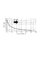
図4は、本実施例における帯電ACのVppと放電電流量Isとの関係を示すグラフ図である。図4に示すように、本実施例では、帯電ACのVppが1100Vに到達すると、放電電流量Isが上昇し始める。ここでは、この放電電流量Isが上昇し始める帯電ACのVppを、感光ドラム1と帯電ローラ2との間の「放電開始電圧2Vth」と呼ぶ。なお、この放電開始電圧2Vthは、帯電ローラ2に直流成分のみからなる電圧を印加した際に感光ドラム1と帯電ローラ2との間での放電が開始する電圧(放電閾値)であるVthの約2倍に相当する。放電開始電圧2Vthは、パッシェンの法則に従い、帯電ローラ2と感光ドラム1との間の空隙距離と気圧によって増減する。
FIG. 4 is a graph showing the relationship between the Vpp of the charged AC and the discharge current amount Is in this embodiment. As shown in FIG. 4, in this embodiment, when the Vpp of the charged AC reaches 1100 V, the discharge current amount Is starts to increase. Here, the Vpp of the charged AC in which the discharge current amount Is starts to increase is referred to as "discharge start voltage 2Vth" between the
本実施例では、帯電ACのVppが1100V未満の場合、放電電流量Isはほぼ0μAであり、放電現象は生じないため、感光ドラム1の表面を所望の状態(帯電DCの電位に略均一に帯電した状態)に帯電させることができない。つまり、帯電位置aを通過した後の感光ドラム1の表面電位は、帯電位置aに到達する前の露光位置bでの露光や転写位置Nでの転写の影響を受けた状態の表面電位になる。帯電ACのVppが1100Vの場合、放電現象が生じ、感光ドラム1の表面をある程度帯電させることができる。しかし、比較的弱い放電しか発生しないので、帯電ムラが発生し、感光ドラム1の表面に所定電位(帯電DCの電位)になっていない領域が発生する。これによって、後述する「地カブリ」の一種が発生する。帯電ACのVppを、1100Vを超えて大きくしていくと、放電電流量Isが増大し、より強い放電が発生して、感光ドラム1の表面を所望の状態に帯電させることができるようになる。
In this embodiment, when the Vpp of the charged AC is less than 1100 V, the discharge current amount Is is almost 0 μA and the discharge phenomenon does not occur. Therefore, the surface of the
ここで、電子写真方式を用いた画像形成装置では、感光ドラム1の表面の暗電位部分にトナーが付着してしまう現象がある。この現象を、「カブリ」と呼ぶ。一般に、カブリは、帯電処理後の感光ドラム1の暗電位と、現像スリーブ41の電位(以下、「現像電位」ともいう。)との電位差によってコントロールされる。この電位差を、「バックコントラスト」と呼ぶ。通常、バックコントラストは、トナーの保持する電荷に対して、感光ドラム1と現像スリーブ41との間に形成される電界が現像スリーブ41側から感光ドラム1側にトナーを飛ばさない電界となるように設定される。
Here, in the image forming apparatus using the electrophotographic method, there is a phenomenon that the toner adheres to the dark potential portion on the surface of the
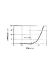
図5は、バックコントラストとカブリの発生程度との関係を示すグラフ図である。図5の横軸はバックコントラストを示し、縦軸はベタ白画像を白紙に印字(通紙)した場合の白紙の反射濃度を測定した値(東京電色反射濃度計 TC−6DS/A30)を示す。反射濃度の単位は%で、値が大きい程カブリが発生していることを示す。図5に示すように、バックコントラストには最適値が存在し、小さすぎても、大きすぎても、カブリの最小値は得られない。通常、画像形成時には、バックコントラストは、カブリが最小になるように設定される。 FIG. 5 is a graph showing the relationship between the back contrast and the degree of fog generation. The horizontal axis of FIG. 5 indicates the back contrast, and the vertical axis represents the measured value (Tokyo Densitometer TC-6DS / A30) of the reflection density of the blank paper when the solid white image is printed (passed) on the blank paper. show. The unit of reflection density is%, and the larger the value, the more fog is generated. As shown in FIG. 5, there is an optimum value for the back contrast, and if it is too small or too large, the minimum value of fog cannot be obtained. Normally, at the time of image formation, the back contrast is set so that fog is minimized.
図6は、感光ドラム1上に付着したトナーの電荷分布を示すグラフ図であり、通常の明電位部分に付着したトナー(印字部のトナー)と後述する「砂地カブリ」を起こしたトナーとを比較したものである。図6の横軸は電荷を示し、縦軸は個数分布を測定した値(ホソカワミクロン Espart analyzer modelEST−III−cs)を示す。バックコントラストが最適値よりも小さい場合に現像スリーブ41から感光ドラム1へと飛翔するトナーは、通常の明電位部分へと飛翔するトナーに比べて、電荷の絶対値が小さなトナーの比率が高い。このようにバックコントラストが最適値よりも小さい場合に暗電位部分にトナーが付着する現象を「地カブリ」と呼ぶ。一方、バックコントラストが最適値よりも大きい場合に現像スリーブ41から感光ドラム1へと飛翔するトナーは、通常の明電位部分へと飛翔するトナーに比べ、正規の帯電極性とは逆極性の電荷を有するトナーの比率が高い。このようにバックコントラストが最適値よりも大きい場合に暗電位部分にトナーが付着する現象を「反転カブリ」と呼ぶ。
FIG. 6 is a graph showing the charge distribution of the toner adhering to the
そして、前述のように帯電ACのVppが小さいことで感光ドラム1の帯電ムラ(暗電位部分の電位ムラ)が発生すると、感光ドラム1の表面におけるミクロ的にバックコントラストが最適値よりも小さい領域にトナーが付着してカブリが発生することがある。この現象を、「砂地カブリ」と呼ぶ。「砂地カブリ」は上述の「地カブリ」の一種であり、砂地カブリを起こしたトナーは、通常の明電位部分に付着するトナーに比べて、電荷の絶対値が小さいトナーの比率が高い。本発明者の検討によれば、砂地カブリを目視で確認できない程度まで十分に低減させるには、帯電ACのVppを2Vth+200Vより大きく設定する必要がある。換言すれば、帯電ACのVppを、次式、
2Vth≦Vpp≦2Vth+200V
を満たす範囲に設定することで、砂地カブリを積極的に発生させることができる。
Then, when charging unevenness (potential unevenness of the dark potential portion) of the
2Vth ≤ Vpp ≤ 2Vth + 200V
By setting the range to satisfy the above conditions, sand fog can be positively generated.
7.供給動作
7−1.砂地カブリを用いた供給動作
前述のように、感光ドラム1へのトナーの供給が少ない状態で感光ドラム1を回転させ続けると、感光ドラム1とクリーニングブレード61との間の摩擦力が上昇する。そして、クリーニングブレード61のびびり、更にはクリーニングブレード61のめくれが発生することがある。クリーニングブレード61の「びびり」や「めくれ」を抑制するためには、非画像形成時にクリーニング位置dにトナーを供給して、感光ドラム1とクリーニングブレード61との間の摩擦力を低減する供給動作(パージ)を実行することが有効である。
7. Supply operation 7-1. Supply operation using sand fog As described above, if the
しかしながら、前述のように、供給動作において通常の印字パターン(ベタ黒や細線)を感光ドラム1に形成すると、その印字パターンのトナー自体のすり抜けによりクリーニング不良が発生することがある。
However, as described above, when a normal print pattern (solid black or thin line) is formed on the
本発明者の検討によれば、このすり抜けの発生程度には、トナーの電荷量が影響することがわかった。供給動作でクリーニング位置dに供給されるトナーの電荷の絶対値は小さい程良い。つまり、電荷の絶対値が相対的に小さいトナーは、感光ドラム1との鏡映力が相対的に低く、電荷の絶対値が相対的に大きいトナーは、感光ドラム1との鏡映力が相対的に高い。電荷の絶対値が相対的に大きいトナーは、鏡映力が相対的に高いため、供給動作において感光ドラム1に貼り付いたままクリーニングブレード61によって掻き取られずにクリーニングブレード61をすり抜けやすい。そのため、供給動作において、電荷の絶対値が相対的に大きいトナーの比率が高い通常の印字パターンのトナーをクリーニング位置dに供給すると、そのトナーがクリーニングブレード61をすり抜けてクリ−ニング不良が発生しやすい。一方、電荷の絶対値が相対的に小さいトナーは、鏡映力が相対的に低いため、クリーニングブレード61によって掻き取られやすい。
According to the study of the present inventor, it has been found that the amount of charge of the toner affects the degree of occurrence of this slip-through. The smaller the absolute value of the toner charge supplied to the cleaning position d in the supply operation, the better. That is, a toner having a relatively small absolute value of electric charge has a relatively low mirroring force with the
そこで、本実施例では、供給動作において、電荷の絶対値が相対的に小さいトナーの比率が高いトナーが感光ドラム1の暗電位部分に付着する前述の「砂地カブリ」を積極的に発生させて、この砂地カブリを起こしたトナーをクリーニング位置dに供給する。具体的には、供給動作における帯電ACのVppを十分に小さくして、電位均し効果を低下させることで、砂地カブリを積極的に発生させる。砂地カブリを起こしたトナーは、電荷の絶対値が相対的に小さく、鏡映力が相対的に低いため、クリーニングブレード61によって容易に掻き取られて、その一部(トナーや外添剤)がクリーニングブレード61の自由端部側の先端に滞留する。これによって、感光ドラム1とクリーニングブレード61との間に潤滑性を付与して、クリーニングブレード61の「びびり」や「めくれ」を抑制できると共に、トナーがクリーニングブレード61をすり抜けることによるクリーニング不良を抑制できる。
Therefore, in this embodiment, in the supply operation, the above-mentioned "sand fog" in which the toner having a high ratio of the toner having a relatively small absolute value of electric charge adheres to the dark potential portion of the
また、帯電ACのVppとクリーニング性には相関があり、帯電ACのVppが小さい方がクリーニング性は向上する。つまり、AC帯電方式を用いる場合、電気的な振動が感光ドラム1を物理的に振動させることによって、すり抜けが発生しやすい。これに対し、供給動作において帯電ACのVppを十分に小さくすることで、上述のような振動によるクリーニング性の低下を抑制することができる。
Further, there is a correlation between the Vpp of the charged AC and the cleaning property, and the smaller the Vpp of the charged AC, the better the cleaning property. That is, when the AC charging method is used, the electric vibration physically vibrates the
つまり、供給動作において帯電ACのVppを十分に小さくすることによって、砂地カブリにより電荷の絶対値が相対的に小さいトナーをクリーニング位置dに供給することだけではなく、振動を減らすことによってもクリーニング不良を抑制することができる。 That is, by sufficiently reducing the Vpp of the charged AC in the supply operation, not only the toner having a relatively small absolute value of the charge due to sand fog is supplied to the cleaning position d, but also the cleaning is defective by reducing the vibration. Can be suppressed.
前述のように、砂地カブリを積極的に発生させるためには、帯電ACのVppを、
2Vth≦Vpp≦2Vth+200V
を満たす範囲に設定する。なお、Vppは、2Vth+100V以下であることがより好ましい。
As mentioned above, in order to positively generate sand fog, the Vpp of the charged AC is used.
2Vth ≤ Vpp ≤ 2Vth + 200V
Set to the range that satisfies. The Vpp is more preferably 2Vth + 100V or less.
つまり、本実施例では、制御部50は、非画像形成時に、感光ドラム1上の所定の領域に現像スリーブ41からトナーを移動させ該トナーをクリーニング位置dに供給する供給動作を実行させることが可能である。制御部50は、供給動作では、上記所定の領域が帯電位置aを通過する際に帯電ローラ2に帯電バイアスを印加させ、かつ、上記所定の領域が現像位置cを通過する際に現像スリーブ41に現像バイアスを印加させる。ここで、上記所定の領域が帯電位置aを通過する際の帯電ACのVppを「Vpp1」、画像形成時の帯電電ACのVppを「Vpp2」、感光ドラム1と帯電ローラ2との間の放電開始電圧を「2Vth」とする。このとき、制御部50は、供給動作では、次式、
Vpp1<Vpp2、及び
2Vth≦Vpp1≦2Vth+200V
を満たすように制御を行う。
That is, in this embodiment, the
Vpp1 <Vpp2 and 2Vth ≤ Vpp1 ≤ 2Vth + 200V
Control to satisfy.
7−2.帯電バイアス、現像バイアスの設定
本実施例における画像形成時及び供給動作時の帯電バイアス及び現像バイアスの設定は次の通りである。
7-2. Setting of charging bias and development bias The setting of charging bias and development bias during image formation and supply operation in this embodiment is as follows.
<画像形成時の設定>
・帯電バイアス
直流成分:−400V
交流成分:Vpp=1500V(「Vpp2」)、f(周波数)=1.5kHz、正弦波
・現像バイアス
直流成分:−300V
交流成分:Vpp=1800V、f=2.5kHz、正弦波
この設定では、砂地カブリは実質的に無視できる反射濃度1%程度に抑制される。
<供給動作時の設定>
・帯電バイアス
直流成分:−400V(画像形成時と同じ設定)
交流成分:Vpp1=1200V(「Vpp1」)、f=1.5kHz、正弦波
・現像バイアス
直流成分:−300V(画像形成時と同じ設定)
交流成分:Vpp=1800V、f=2.5kHz、正弦波(画像形成時と同じ設定)
この設定では、反射濃度8%程度の砂地カブリが発生する。供給動作で感光ドラム1にトナーを付着させる時間は200msec、トナーを付着させる感光ドラム1の回転方向の幅は40mm、感光ドラム1に付着させるトナーの量は12mgである。なお、供給動作では、感光ドラム1の回転軸線方向における画像形成可能領域の略全域に、砂地カブリを起こしたトナーが付着する。
<Settings at the time of image formation>
・ Charging bias DC component: -400V
AC component: Vpp = 1500V (“Vpp2”), f (frequency) = 1.5kHz, sine wave ・ Development bias DC component: -300V
AC component: Vpp = 1800V, f = 2.5kHz, sine wave With this setting, sand fog is suppressed to a reflection density of about 1%, which is substantially negligible.
<Settings during supply operation>
・ Charging bias DC component: -400V (same setting as when forming the image)
AC component: Vpp1 = 1200V (“Vpp1”), f = 1.5kHz, sine wave ・ Development bias DC component: -300V (same setting as when forming the image)
AC component: Vpp = 1800V, f = 2.5kHz, sine wave (same setting as when forming the image)
With this setting, sand fog with a reflection density of about 8% occurs. The time for adhering the toner to the
7−3.供給動作の実行制御
本実施例では、感光ドラム1の回転距離が、LETTERサイズ換算で100枚の印刷を連続して行った場合に相当する感光ドラム1の回転距離に達した後の、次のジョブの前回転工程において供給動作が実行される。
7-3. Execution control of supply operation In this embodiment, after the rotation distance of the
図7は、本実施例における供給動作を実行するか否かを判断する制御の手順の概略を示すフローチャート図である。制御部50は、ジョブの開始が指示されると、前回転工程を開始させる(S1)。次に、制御部50は、回転距離カウンタ11から読み込んだ前回の供給動作を実行してからの回転距離が、閾値であるLETTERサイズ換算での100枚連続印刷相当の回転距離以上であるか否かを判断する(S2)。そして、制御部50は、S2において閾値以上(“Yes”)であると判断した場合は、今回の前回転工程中に供給動作を実行することを決定し(S3)、回転距離カウンタ11のカウント値を0にリセットする(S4)。一方、制御部50は、S2において100枚未満である(“No”)と判断した場合は、今回の前回転工程中に供給動作を実行しないことを決定する(S5)。なお、制御部50は、その後、S2における判断に応じて供給動作を含むか又は含まない所定の前回転工程が終了し次第、画像形成工程を開始することになる。
FIG. 7 is a flowchart showing an outline of a control procedure for determining whether or not to execute the supply operation in the present embodiment. When the
7−4.シーケンス
図8は、本実施例における供給動作を実行する場合の各部の動作状態の一例を示すシーケンスチャート図である。
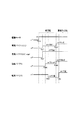
7-4. Sequence FIG. 8 is a sequence chart diagram showing an example of the operating state of each part when the supply operation in this embodiment is executed.
前回転工程が開始されると、まず、駆動モータM1の駆動が開始される(T111)。次に、帯電DC及び帯電ACの印加が開始される(T121、T131)。このとき、帯電ACのVppは「Vpp1」に設定され、帯電DCは画像形成時と同じ値に設定される。次に、「Vpp1」の印加が開始された時に帯電位置aにあった感光ドラム1上の位置が現像位置cに到達するタイミングと同期させて、現像DC及び現像AC(現像DCのみ図示)の印加が開始される(T141)。これにより、砂地カブリが発生し、感光ドラム1にトナーが付着する。
When the pre-rotation process is started, first, the drive of the drive motor M1 is started (T111). Next, the application of the charged DC and the charged AC is started (T121, T131). At this time, the Vpp of the charged AC is set to "Vpp1", and the charged DC is set to the same value as at the time of image formation. Next, the development DC and the development AC (only the development DC is shown) are synchronized with the timing when the position on the
次に、「Vpp1」の印加が開始された時に帯電位置aにあった感光ドラム1上の位置(砂地カブリを起こしたトナー)が転写位置Nに到達するタイミングと同期させて、負極性の転写バイアス(本実施例では−500V)の印加が開始される(T151)。これは、次のような理由によるものである。つまり、砂地カブリを起こしたトナーは、電荷の絶対値が相対的に小さい負極性に帯電したトナーの比率が高い。そのため、このトナーと同極性(画像形成時の転写バイアスとは逆極性)の転写バイアスを印加して、できるだけ多くのトナーを電気的に転写ローラ5から反発させて(つまり感光ドラム1に押し付ける側に付勢し)、クリーニング位置dに供給するためである。
Next, the negative electrode transfer is synchronized with the timing at which the position (toner causing sand fog) on the
次に、感光ドラム1上の砂地カブリを発生させるべき所定の領域が帯電位置aを通過し終えた時以降のタイミングで、帯電ACのVppが「Vpp1」から「Vpp2」に切り替えられ、画像形成工程に移行する(T132)。その後、「Vpp2」に切り替えられた時に帯電位置aにあった感光ドラム1上の位置が転写位置Nに到達するタイミングと同期させて、正極性の転写バイアス(本実施例では+1500V)の印加が開始される(T152)。
Next, the Vpp of the charging AC is switched from "Vpp1" to "Vpp2" at the timing after the predetermined region on the
なお、図14は、供給動作を実行しない場合の各部の動作状態の一例を示すシーケンスチャート図である。 Note that FIG. 14 is a sequence chart diagram showing an example of the operating state of each part when the supply operation is not executed.
7−5.効果
次に、本実施例と、供給動作において通常の印字パターンのトナーをクリーニング位置dに供給した場合(比較例)とで、クリーニング不良の発生程度を比較した。比較例では、供給動作において、感光ドラム1の回転軸線方向における画像形成可能領域の略全域にわたる帯状のベタ黒画像を形成することで、本実施例と同じ量のトナーを感光ドラム1に付着させた。比較例の画像形成装置の構成及び動作は、上記の点を除いて本実施例の画像形成装置100と実質的に同じである。クリーニング不良(すり抜け)は目視で確認し、無視できない程度に発生した場合を×(不良)、発生しないか無視できる程度の場合を○(良好)として評価した。評価結果を表1に示す。また、本実施例と比較例について、耐久試験(30k枚)を行って「びびり」や「めくれ」の発生の有無を確認した。
7-5. Effect Next, the degree of occurrence of cleaning defects was compared between this embodiment and the case where toner of a normal print pattern was supplied to the cleaning position d in the supply operation (comparative example). In the comparative example, in the supply operation, a strip-shaped solid black image covering substantially the entire image-forming region in the rotation axis direction of the

本実施例及び比較例のいずれにおいても、「びびり」や「めくれ」を十分に抑制することができることがわかった。しかし、表1に示すように、比較例ではすり抜けが発生した。これに対し、本実施例ではすり抜けは発生しなかった。 It was found that "chatter" and "turning" can be sufficiently suppressed in both this example and the comparative example. However, as shown in Table 1, slip-through occurred in the comparative example. On the other hand, no slip-through occurred in this example.
また、本実施例における帯電ACのVppを変更した場合について同様の試験を行ったところ、Vppが1300V(すなわち、2Vth+200V)を越えると「びびり」に起因するクリーニング不良が発生することがあった。これは、供給動作において十分に砂地カブリを発生させることができず、十分な量のトナーをクリーニング位置dに供給できなかったためであると考えられる。 Further, when the same test was performed when the Vpp of the charged AC in this example was changed, when the Vpp exceeded 1300V (that is, 2Vth + 200V), a cleaning defect due to "chatter" may occur. It is considered that this is because the sand fog could not be sufficiently generated in the supply operation and a sufficient amount of toner could not be supplied to the cleaning position d.
以上説明したように、本実施例によれば、AC帯電方式を用いる場合に、非画像形成時に感光ドラム1とクリーニングブレード61との当接部に十分にトナーを供給できると共に、そのトナーによるクリーニング不良の発生を抑制することができる。
As described above, according to the present embodiment, when the AC charging method is used, sufficient toner can be supplied to the contact portion between the
[実施例2]
次に、本発明の他の実施例について説明する。本実施例の画像形成装置100の基本的な構成及び動作は、実施例1の画像形成装置のものと同じである。したがって、本実施例の画像形成装置において、実施例1の画像形成装置のものと同一又は対応する機能あるいは構成を有する要素については、実施例1と同一の符号を付して詳しい説明は省略する。
[Example 2]
Next, another embodiment of the present invention will be described. The basic configuration and operation of the
1.本実施例の供給動作
本実施例では、LETTERサイズ換算で100枚の印刷を連続して行った場合に相当する感光ドラム1の回転距離ごとに、平均印字率がカウント(非画像形成時は0%としてカウント)される。この平均印字率は、概略、画像形成時に画像画素数を積算し、その積算値の、現時点までの感光ドラム1の回転距離に対応する画像形成可能領域の全画素数に対する割合(%)を算出することで求めることができる。そして、本実施例では、感光ドラム1の回転距離が上記100枚連続印刷相当の回転距離に達した後の次のジョブの前回転工程において、平均印字率が閾値以下の場合に供給動作を実行する。
1. 1. Supply operation of this embodiment In this embodiment, the average printing rate is counted for each rotation distance of the
ここで、画像形成時の印字率は印字する画像によって変動する。また、感光ドラム1へのトナーの供給が無い時間、例えば前回転工程の時間は一定ではない。前回転工程は、例えば、次のような場合に長くなることがある。例えば、画像展開に時間がかかる場合が挙げられる。また、現像装置の攪拌部材と感光ドラムの駆動モータが共通化された構成において、現像装置内の現像剤を通常より長く攪拌する場合が挙げられる。また、定着装置と感光ドラムの駆動モータが共通化された構成において、定着装置の昇温に通常より長く時間がかかる場合が挙げられる。そのため、上述のように非画像形成時の感光ドラム1の回転距離も考慮した平均印字率に基づいて供給動作を実行するか否かを判断することで、より適切なタイミングで供給動作を行うことができる。
Here, the print rate at the time of image formation varies depending on the image to be printed. Further, the time during which the toner is not supplied to the
また、本実施例では、上記平均印字率の閾値は、環境の温度に応じて変更される。相対的に低温の場合には、クリーニングブレード61が相対的に固くなり、感光ドラム1とクリーニングブレード61との間の摩擦力が上昇し、「びびり」や「めくれ」が発生しやすくなる。そのため、平均印字率の閾値は、低温環境ほど大きい値に変更される。
Further, in this embodiment, the threshold value of the average printing rate is changed according to the temperature of the environment. When the temperature is relatively low, the
図3を参照して、本実施例では、制御部50には、計数手段としての印字率カウンタ(記憶部)12が接続されている。制御部50は、上述のようにして算出した平均印字率を印字率カウンタ12に記憶させる。また、本実施例では、制御部50には、装置本体110の内部又は外部の少なくとも一方の温度を検知する温度検知手段としての、装置本体110の内部の温度を検知する温度センサ13が接続されている。温度センサ13の検知結果を示す信号は、制御部50に入力される。
With reference to FIG. 3, in this embodiment, a print rate counter (storage unit) 12 as a counting means is connected to the
本実施例における、画像形成時及び供給動作時の帯電バイアス及び現像バイアスの設定、並びに供給動作において感光ドラム1に付着させるトナー量(時間、幅、質量)の設定は、実施例1と同じである。また、本実施例では、供給動作を実行する場合の各部の動作は、実施例1と同様に図8のシーケンスチャート図に従う。一方、本実施例では、供給動作を実行しない場合の各部の動作は、実施例1と同様に図14のシーケンスチャート図に従う。
In this embodiment, the setting of the charge bias and the development bias during the image formation and the supply operation, and the setting of the toner amount (time, width, mass) to be attached to the
図9は、本実施例における供給動作を実行するか否かを判断する制御の手順の概略を示すフローチャート図である。制御部50は、ジョブの開始が指示されると、前回転工程を開始させる(S1)。次に、制御部50は、回転距離カウンタ11から読み込んだ前回の供給動作を実行してからの回転距離が、閾値であるLETTERサイズ換算での100枚連続印刷相当の回転距離以上であるか否かを判断する(S2)。次に、制御部50は、S2において閾値以上(“Yes”)であると判断した場合は、温度センサ13から読み込んだ機内温度Xが、低温(0℃<X≦15℃)、常温(15℃<X≦25℃)、高温(25℃<X)のいずれであるかを判断する(S3)。次に、制御部50は、S3で低温であると判断した場合、印字率カウンタ12から読み込んだ前回の供給動作を実行してからの平均印字率が、第1の閾値としての10%以下であるか否かを判断する(S4)。また、制御部50は、S3で常温であると判断した場合、印字率カウンタ12から読み込んだ前回の供給動作を実行してからの平均印字率が、第2の閾値としての4%以下であるか否かを判断する(S5)。また、制御部50は、S3で高温であると判断した場合、印字率カウンタ12から読み込んだ前回の供給動作を実行してからの平均印字率が、第3の閾値としての2%以下であるか否かを判断する(S6)。そして、制御部50は、S4、S5、S6において閾値以下(“Yes”)であると判断した場合は、今回の前回転工程中に供給動作を実行することを決定し(S7)、印刷枚数カウンタ11、印字率カウンタ12のカウント値を0にリセットする(S8)。一方、制御部50は、S2において閾値未満である(“No”)と判断した場合、あるいはS4、S5、S6において閾値より大きいと判断した場合は、今回の前回転工程中に供給動作を実行しないことを決定する(S9)。
FIG. 9 is a flowchart showing an outline of a control procedure for determining whether or not to execute the supply operation in the present embodiment. When the
20℃環境において1枚間欠で30k枚の印刷を、印字率を異ならせてそれぞれ行った場合の、プロセスカートリッジ7の寿命までの供給動作によるトナーの総消費量は、それぞれ次の通りである。なお、1枚間欠とは、1枚印刷するごとに前回転工程、画像形成工程、後回転工程が行われるジョブを繰り返す運転状態である。印字率5%の場合は、供給動作が必要と見なされず、供給動作によるトナーの消費は無い。一方、印字率1%の場合は、供給動作により3600mgのトナーが消費される。 The total amount of toner consumed by the supply operation up to the life of the process cartridge 7 when printing 30 k sheets intermittently in a 20 ° C. environment at different printing rates is as follows. In addition, one sheet intermittent is an operation state in which a job in which a front rotation step, an image forming step, and a back rotation step are performed every time one sheet is printed is repeated. When the printing rate is 5%, the supply operation is not considered necessary, and the toner is not consumed by the supply operation. On the other hand, when the printing rate is 1%, 3600 mg of toner is consumed by the supply operation.
このように、本実施例によれば、必要に応じて適切なタイミングで供給動作を実行することで、良好なクリーニング性能を確保しつつ、トナーを節約することができる。 As described above, according to the present embodiment, by executing the supply operation at an appropriate timing as needed, it is possible to save toner while ensuring good cleaning performance.
2.変形例
ここで、供給動作の実行の有無を判断する制御の変形例について説明する。制御部50は、感光ドラム1とクリーニングブレード61との間の摩擦力と相関する指標値が所定の条件を満たす場合に、非画像形成時に供給動作を実行させることができる。
2. 2. Modification example Here, a modification of the control for determining whether or not the supply operation is executed will be described. The
例えば、実施例1では、回転距離カウンタ11による、感光ドラム1の回転方向の移動距離と相関する指標値としての回転距離の計数結果が、閾値以上の場合に、非画像形成時に供給動作を実行させた。前述のように、感光ドラム1とクリーニングブレード61との間の摩擦力は、感光ドラム1へのトナーの供給が少ない状態で感光ドラム1を回転させることで上昇する。そのため、回転距離カウンタ11による、非画像形成時の感光ドラム1の回転方向の移動距離と相関する指標値としての回転距離の計数結果が、閾値以上の場合に、非画像形成時に供給動作を実行させるようにしてもよい。
For example, in the first embodiment, when the counting result of the rotation distance as an index value correlating with the movement distance in the rotation direction of the
また、実施例1のように感光ドラム1の回転距離に応じて供給動作の実行の有無を判断する場合に、本実施例と同様に、回転距離の閾値を、環境の温度に応じて変更することができる。この場合、制御部50は、第1の温度の場合よりも、第1の温度よりも高い第2の温度の場合の閾値の方を大きくするように変更する。これは、上述のように、相対的に低温の場合に、感光ドラム1とクリーニングブレード61との間の摩擦力が上昇しやすいからである。別法として、回転距離の閾値を、現像装置4の使用量に応じて変更することができる。現像装置4の使用量と相関する指標値としては、現像スリーブ41の回転回数や回転時間、攪拌部材45の回転回数や回転時間、印刷枚数などの任意の値を用いることができる。この場合、画像形成装置100に、該指標値を計数する使用量計数手段としてカウンタ(記憶部)を設ければよい。そして、この場合、制御部50は、使用量の計数結果が第1の値の場合よりも、第1の値よりも大きい第2の値の場合の閾値の方を小さくするように変更する。これは、現像装置4の消耗が進むにつれ、現像剤の流動性が低下し、供給動作時に感光ドラム1とクリーニングブレード61との間に与えられる潤滑性が低下しやすいからである。
Further, when determining whether or not the supply operation is executed according to the rotation distance of the
また、感光ドラム1の回転方向の移動距離と相関する指標値は、感光ドラム1の回転距離に限定されるものではなく、回転数や回転時間などを用いてもよい。また、「びびり」や「めくれ」の所望の抑制程度などに応じて、例えば印刷枚数(所定のサイズ換算での印刷枚数など)を用いてもよい。
Further, the index value that correlates with the moving distance of the
また、本実施例では、印字率カウンタ12による、感光ドラム1が回転方向に所定の距離だけ移動する間に感光ドラム1に供給されたトナーの量と相関する指標値としての平均印字率の計数結果が、閾値以下の場合に、非画像形成時に供給動作を実行させた。そして、平均印字率の閾値を、環境の温度に応じて変更した。このとき、制御部50は、第1の温度の場合よりも、第1の温度よりも高い第2の温度の場合の閾値を小さくするように変更した。これは、上述のように、相対的に低温の場合に、感光ドラム1とクリーニングブレード61との間の摩擦力が上昇しやすいからである。別法として、平均印字率の閾値を、上記同様、現像装置4の使用量に応じて変更することができる。この場合、制御部50は、使用量の計数結果が第1の値の場合よりも、第1の値よりも大きい第2の値の場合の閾値の方を大きくするように変更する。これは、上述のように、現像装置4の消耗が進むにつれ、現像剤の流動性が低下し、供給動作時に感光ドラム1とクリーニングブレード61との間に与えられる潤滑性が低下しやすいからである。
Further, in this embodiment, the printing rate counter 12 counts the average printing rate as an index value that correlates with the amount of toner supplied to the
また、例えば毎回の前回転工程などの所定のタイミングで、供給動作の実行の有無を環境の温度や現像装置4の使用量によって判断するようにしてもよい。環境の温度によって判断する場合、制御部50は、温度が閾値以下の場合に、非画像形成時に供給動作を実行させるように制御することができる。また、現像装置4の使用量によって判断する場合、制御部50は、使用量の計数結果が閾値以上の場合に、非画像形成時に供給動作を実行させるように制御することができる。
Further, for example, at a predetermined timing such as each pre-rotation step, whether or not the supply operation is executed may be determined based on the temperature of the environment and the amount of the developing
[実施例3]
次に、本発明の他の実施例について説明する。本実施例の画像形成装置100の基本的な構成及び動作は、実施例1の画像形成装置のものと同じである。したがって、本実施例の画像形成装置において、実施例1の画像形成装置のものと同一又は対応する機能あるいは構成を有する要素については、実施例1と同一の符号を付して詳しい説明は省略する。
[Example 3]
Next, another embodiment of the present invention will be described. The basic configuration and operation of the
本実施例では、前回転工程において、感光ドラム1の駆動モ−タM1の回転トルクが閾値以上の場合に、感光ドラム1とクリーニングブレード61との間の潤滑性が不足していると判断し、帯電ACのVppを小さくして砂地カブリを積極的に発生させる。また、前回転工程において、砂地カブリを積極的に発生させた結果、回転トルクが閾値未満に低下した場合に、帯電ACのVppを再び大きくする。このように、実際に感光ドラム1とクリーニングブレード61との間の潤滑性が損なわれているタイミングで供給動作を実行することで、供給動作によるトナーの消費を減らすことができる。
In this embodiment, it is determined that the lubricity between the
つまり、制御部50は、非画像形成時に、帯電ACのVppの切り替えを行うことが可能である。ここで、非画像形成時に感光ドラム1上の砂地カブリを発生させる所定の領域とは別の領域が帯電位置aを通過する際の帯電ACのVppを「Vpp3」とする。このとき、制御部50は、次式、
Vpp1<Vpp3<Vpp2
を満たすように上記Vppの切り替えの制御を行う。実施例1で説明したように、「Vpp1」は、積極的に砂地カブリを発生させ、トナーをクリーニング位置dに供給するための設定である。「Vpp2」は、砂地カブリを無視できる程度に抑制し、帯電ムラの無い略均一な帯電を行うための設定である。そして、「Vpp3」は、砂地カブリを無視できる程度に抑制すると共に、若干の帯電ムラの発生は許容しつつ感光ドラム1の表面の削れを抑制するための設定である。
That is, the
Vpp1 <Vpp3 <Vpp2
The switching of Vpp is controlled so as to satisfy the above conditions. As described in the first embodiment, "Vpp1" is a setting for positively generating sand fog and supplying toner to the cleaning position d. "Vpp2" is a setting for suppressing sand fog to a negligible level and performing substantially uniform charging without uneven charging. The "Vpp3" is a setting for suppressing sand fog to a negligible level and suppressing scraping of the surface of the
なお、本実施例では、実施例1と同様に、「Vpp1」の印加時に帯電位置aを通過した感光ドラム1上の領域が現像位置cを通過する時には現像バイアスが印加され、転写位置Nを通過する時には画像形成時とは逆極性の転写バイアスが印加される。一方、本実施例では、「Vpp3」の印加時に帯電位置aを通過した感光ドラム1上の領域が現像位置cを通過する時には現像バイアスの印加は停止され、転写位置Nを通過する時には転写バイアスの印加は停止される。つまり、「Vpp3」の印加時に帯電位置aを通過した感光ドラム1上の領域に対しては、積極的にはトナーを供給しない。
In this embodiment, as in the first embodiment, when the region on the
図3を参照して、本実施例では、制御部50には、感光ドラム1の駆動モータM1に内蔵された、トルク検知手段としてのトルクゲージ14が接続されている。トルクゲージ14の検知結果を示す信号は、制御部50に入力される。
With reference to FIG. 3, in this embodiment, a
本実施例における画像形成時及び前回転工程時の帯電バイアス及び現像バイアスの設定は次の通りである。 The settings of the charging bias and the developing bias at the time of image formation and the pre-rotation step in this embodiment are as follows.
<画像形成時の設定>
・帯電バイアス
直流成分:−400V
交流成分:Vpp=1500V(「Vpp2」)、f=1.5kHz、正弦波
・現像バイアス
直流成分:−300V
交流成分:Vpp=1800V、f=2.5kHz、正弦波
<前回転工程時の設定>
・帯電バイアス
直流成分:−400V(画像形成時と同じ設定)
交流成分:供給動作時以外のVpp=1400V(「Vpp3」)、
供給動作時のVpp=1200V(「Vpp1」)、
f=1.5kHz、正弦波
・現像バイアス
直流成分:−300V(画像形成時と同じ設定)
交流成分:Vpp=1800V、f=2.5kHz、正弦波(画像形成時と同じ設定)
<Settings at the time of image formation>
・ Charging bias DC component: -400V
AC component: Vpp = 1500V (“Vpp2”), f = 1.5kHz, sine wave ・ Development bias DC component: -300V
AC component: Vpp = 1800V, f = 2.5kHz, sine wave <Settings during the previous rotation process>
・ Charging bias DC component: -400V (same setting as when forming the image)
AC component: Vpp = 1400V (“Vpp3”) other than during supply operation,
Vpp = 1200V (“Vpp1”) during supply operation,
f = 1.5kHz, sine wave ・ Development bias DC component: -300V (same setting as when forming the image)
AC component: Vpp = 1800V, f = 2.5kHz, sine wave (same setting as when forming the image)
本実施例では、前回転工程中に、駆動モータM1の回転トルクの値が閾値である5kgcm以上になった場合は、感光ドラム1とクリーニングブレード61との間の潤滑性が低下していると見なし、帯電ACのVppを「Vpp1」に設定する。これにより、反射濃度8%程度の砂地カブリが発生する。また、前回転工程中に、駆動モータM1の回転トルクの値が閾値である5kgcm未満になった場合は、感光ドラム1とクリーニングブレード61との間の潤滑性が十分であると見なし、帯電ACのVppを「Vpp3」に設定する。この設定で、供給動作において感光ドラム1に付着するトナー量(時間、幅、質量)は、約200msec、約40mm、約12mgであった。
In this embodiment, when the value of the rotational torque of the drive motor M1 becomes 5 kg cm or more, which is the threshold value, during the pre-rotation process, the lubricity between the
図10は、本実施例における供給動作を実行する場合の各部の動作状態の一例を示すシーケンスチャート図である。ここでは、前回転工程は、例えば、定着装置9を温めるあるいは現像装置4内の現像剤をほぐすなどのために、供給動作とは別の要因で決められる時間の間だけ行われるものとする。
FIG. 10 is a sequence chart diagram showing an example of the operating state of each part when the supply operation in this embodiment is executed. Here, it is assumed that the pre-rotation step is performed only for a time determined by a factor different from the supply operation, for example, to heat the
前回転工程が開始されると、まず、駆動モータM1の駆動が開始される(T211)。次に、帯電DC及び帯電ACの印加が開始される(T221、T231)。このとき、帯電ACのVppは「Vpp3」に設定され、帯電DCは画像形成時と同じ値に設定される。また、前回転工程の開始直後からトルクゲージ14の検知結果がモニターされながら、前回転工程が続けられる。そして、感光ドラム1とクリーニングブレード61との間の潤滑性が次第に損なわれていき、トルクゲージ14の検知結果が5kgcm以上になったタイミングで、帯電ACのVppが「Vpp3」から「Vpp1」に切り替えられる(T232)。次に、「Vpp1」の印加が開始された時に帯電位置aにあった感光ドラム1上の位置が現像位置cに到達するタイミングと同期させて、現像DC及び現像AC(現像DCのみ図示)の印加が開始される(T241)。次に、「Vpp1」の印加が開始された時に帯電位置aにあった感光ドラム1上の位置(砂地カブリを起こしたトナー)が転写位置Nに到達するタイミングと同期させて、負極性の転写バイアス(本実施例では−500V)の印加が開始される(T251)。
When the pre-rotation process is started, first, the drive of the drive motor M1 is started (T211). Next, the application of the charged DC and the charged AC is started (T221, T231). At this time, the Vpp of the charged AC is set to "Vpp3", and the charged DC is set to the same value as at the time of image formation. Further, the front rotation process is continued while the detection result of the
次に、感光ドラム1とクリーニングブレード61との間の潤滑性が次第に復帰していき、トルクゲージ14の検知結果が5kgcm未満になったタイミングで、帯電ACのVppが「Vpp1」から再び「Vpp3」に切り替えられる(T233)。次に、再度「Vpp3」に切り替えられた時に帯電位置aにあった感光ドラム1上の位置が現像位置cに到達するタイミングと同期させて、現像DC及び現像ACの印加が停止される(T242)。また、再度「Vpp3」に切り替えられた時に帯電位置aにあった感光ドラム1上の位置が転写位置Nに到達するタイミングと同期させて、転写バイアスの印加が停止される(T252)。
Next, the lubricity between the
次に、前回転工程の終了後に、帯電ACのVppが「Vpp3」から「Vpp2」に切り替えられ、画像形成工程に移行する(T234)。次に、「Vpp2」に切り替えられた時に帯電位置aにあった感光ドラム1上の位置が現像位置cに到達するタイミングと同期させて、現像DC及び現像ACの印加が開始される(T243)。その後、「Vpp2」に切り替えられた時に帯電位置aにあった感光ドラム1上の位置が転写位置Nに到達するタイミングと同期させて、正極性の転写バイアス(本実施例では+1500V)の印加が開始される(T253)。
Next, after the completion of the pre-rotation step, the Vpp of the charged AC is switched from "Vpp3" to "Vpp2", and the process proceeds to the image forming step (T234). Next, the application of the developing DC and the developing AC is started in synchronization with the timing when the position on the
表2は、20℃環境において1枚間欠で30k枚の印刷を、実施例1と本実施例の画像形成装置で行った場合の、プロセスカートリッジ7の寿命までの供給動作によるトナーの総消費量の違いを示している。 Table 2 shows the total amount of toner consumed by the supply operation up to the life of the process cartridge 7 when printing 30 k sheets intermittently in an environment of 20 ° C. using the image forming apparatus of Example 1 and this example. Shows the difference.
表2に示すように、本実施例では、実施例1よりも供給動作によるトナーの消費を減らすことができる。なお、本実施例について、実施例1で説明したのと同様に、クリーニング不良(すり抜け)の発生、及び「びびり」や「めくれ」の発生程度を調べたが、クリーニング不良、及び「びびり」や「めくれ」は十分に抑制することができた。 As shown in Table 2, in this embodiment, the consumption of toner due to the supply operation can be reduced as compared with the first embodiment. In addition, about this Example, the occurrence of cleaning failure (passing through) and the degree of occurrence of "chatter" and "turning over" were investigated in the same manner as described in Example 1, but the cleaning failure and "chatter" and "Turning" could be sufficiently suppressed.
このように、本実施例によれば、良好なクリーニング性能を確保しつつ、トナーを節約することができる。 As described above, according to this embodiment, toner can be saved while ensuring good cleaning performance.
なお、トルク検知手段は、トルク値自体に限らず、駆動モータM1の回転トルクと相関する指標値を検知するものであればよく、制御部50は、その指標値の検知結果が閾値以上の場合に、非画像形成時に供給動作を実行させるようになっていればよい。 The torque detecting means is not limited to the torque value itself, but may be any one that detects an index value that correlates with the rotational torque of the drive motor M1. In addition, it suffices if the supply operation is executed at the time of non-image formation.
[実施例4]
次に、本発明の他の実施例について説明する。本実施例の画像形成装置100の基本的な構成及び動作は、実施例1の画像形成装置のものと同じである。したがって、本実施例の画像形成装置において、実施例1の画像形成装置のものと同一又は対応する機能あるいは構成を有する要素については、実施例1と同一の符号を付して詳しい説明は省略する。
[Example 4]
Next, another embodiment of the present invention will be described. The basic configuration and operation of the
実施例1〜3では、前回転工程時に供給動作を実行する例を説明した。本実施例では、紙間工程時に供給動作を実行する例を説明する。 In Examples 1 to 3, an example in which the supply operation is executed during the pre-rotation process has been described. In this embodiment, an example of executing the supply operation during the paper-to-paper process will be described.
本実施例における、画像形成時及び紙間工程時(供給動作時)の帯電バイアス及び現像バイアスの設定、並びに供給動作において感光ドラム1に付着させるトナー量(時間、幅、質量)の設定は、実施例1と同じである。
In this embodiment, the setting of the charging bias and the developing bias at the time of image formation and the paper-to-paper process (during the supply operation), and the setting of the amount of toner (time, width, mass) to be attached to the
通常汎用されるA4サイズやLETTERサイズの記録材Pよりも小サイズの記録材Pを用いる場合、あるいは両面印刷を行う場合には、紙間工程の時間が長く設定されることがある。なお、紙間工程の時間は、概略、感光ドラム1上の先行する画像形成工程のための画像形成可能領域と、後続の画像形成工程のための画像形成可能領域との間の領域が、感光ドラム1の回転方向の所定位置を通過するのにかかる時間である。このような場合、感光ドラム1へトナーが供給されない時間が長いため、感光ドラム1とクリーニングブレード61との間の潤滑性が損なわれやすい。そこで、本実施例では、上述のように小サイズの記録材Pを用いる場合及び両面印刷を行う場合に、紙間工程時に供給動作を実行する。
When a recording material P having a size smaller than that of the A4 size or LETTER size recording material P which is generally used is used, or when double-sided printing is performed, the time of the paper-to-paper process may be set longer. It should be noted that the time of the paper-to-paper step is roughly such that the region between the image-formable region for the preceding image-forming step on the
図11は、本実施例における供給動作を実行する場合の各部の動作状態の一例を示すシーケンスチャート図である。 FIG. 11 is a sequence chart diagram showing an example of the operating state of each part when the supply operation in this embodiment is executed.
駆動モータM1は、先行する画像形成工程、紙間工程、及び後続の画像形成工程を通して駆動されている。また、帯電DC、並びに、現像DC及び現像AC(現像DCのみ図示)は、先行する画像形成工程、紙間工程、及び後続の画像形成工程を通して同じ値とされる。そして、帯電ACのVppは、紙間工程が開始されるタイミングで、「Vpp2」から「Vpp1」に切り替えられる(T331)。また、「Vpp1」の印加が開始された時に帯電位置aにあった感光ドラム1上の位置(砂地カブリを起こしたトナー)が転写位置Nに到達するタイミングと同期させて、転写バイアスは正極性から負極性に切り替えられる(T351)。本実施例では、正極性の転写バイアスは+1500V、負極性の転写バイアスは−500Vである。また、紙間工程中に感光ドラム1上の砂地カブリを発生させるべき所定の領域が帯電位置aを通過し終えた時以降のタイミングで、次の画像形成工程に備えて帯電ACのVppが「Vpp1」から再度「Vpp2」に切り替えられる(T332)。その後、「Vpp2」に切り替えられた時に帯電位置aにあった感光ドラム1上の位置が転写位置Nに到達するタイミングと同期させて、転写バイアスが負極性から再度正極性に切り替えられる(T352)。
The drive motor M1 is driven through a preceding image forming step, a paper-to-paper step, and a subsequent image forming step. Further, the charged DC, the developing DC and the developing AC (only the developing DC is shown) have the same values throughout the preceding image forming step, the inter-paper step, and the subsequent image forming step. Then, the Vpp of the charged AC is switched from "Vpp2" to "Vpp1" at the timing when the paper-to-paper process is started (T331). Further, the transfer bias is positive in synchronization with the timing when the position (toner causing sand fog) on the
なお、実施例1〜3で説明した供給動作の実行の有無を判断する手法は、本実施例のように紙間工程中に供給動作を行う場合にも任意に適用することができる。 The method for determining whether or not the supply operation is executed described in Examples 1 to 3 can be arbitrarily applied even when the supply operation is performed during the paper-to-paper process as in the present embodiment.
[実施例5]
次に、本発明の他の実施例について説明する。本実施例の画像形成装置100の基本的な構成及び動作は、実施例1の画像形成装置のものと同じである。したがって、本実施例の画像形成装置において、実施例1の画像形成装置のものと同一又は対応する機能あるいは構成を有する要素については、実施例1と同一の符号を付して詳しい説明は省略する。
[Example 5]
Next, another embodiment of the present invention will be described. The basic configuration and operation of the
実施例1〜3では前回転工程時、実施例4では紙間工程時に供給動作を実行する例を説明した。本実施例では、後回転工程時に供給動作を実行する例を説明する。 Examples 1 to 3 have described an example in which the supply operation is executed during the front rotation process, and Example 4 has described an example in which the supply operation is executed during the paper-to-paper process. In this embodiment, an example of executing the supply operation during the back rotation process will be described.
本実施例における、画像形成時及び後回転工程時(供給動作時)の帯電バイアス及び現像バイアスの設定、並びに供給動作において感光ドラム1に付着させるトナー量(時間、幅、質量)の設定は、実施例1と同じである。
In this embodiment, the setting of the charging bias and the developing bias at the time of image formation and the post-rotation process (during the supply operation), and the setting of the amount of toner (time, width, mass) to be attached to the
本実施例では、感光ドラム1の回転距離が、LETTERサイズ換算で100枚の印刷を連続して行った場合に相当する感光ドラム1の回転距離に到達した後(典型的には直後)の後回転工程において供給動作が実行される。
In this embodiment, after the rotation distance of the
図12は、本実施例における供給動作を実行する場合の各部の動作状態の一例を示すシーケンスチャート図である。 FIG. 12 is a sequence chart diagram showing an example of the operating state of each part when the supply operation in this embodiment is executed.
画像形成時は駆動モータM1は駆動されている。そして、帯電ACのVppは、後回転工程が開始されるタイミングで、「Vpp2」から「Vpp1」に切り替えられる(T431)。帯電DC、並びに、現像DC及び現像AC(現像DCのみ図示)は、画像形成工程時と同じ値に維持される。転写バイアスは、「Vpp1」の印加が開始されたタイミングと同期させて、正極性(本実施例では+1500V)から負極性(本実施例では−500V)に切り替えられる(T451)。次に、後回転中に感光ドラム1上の砂地カブリを発生させるべき所定の領域が現像位置cを通過し終えた時以降のタイミングで、現像DC及び現像ACの印加が停止される(T441)。次に、帯電DC及び帯電ACの印加が停止されると共に(T421、T432)、転写バイアスの印加が停止される(T452)。その後、駆動モータM1の駆動が停止される(T411)。
At the time of image formation, the drive motor M1 is driven. Then, the Vpp of the charged AC is switched from "Vpp2" to "Vpp1" at the timing when the post-rotation process is started (T431). The charged DC, the developing DC and the developing AC (only the developing DC is shown) are maintained at the same values as in the image forming step. The transfer bias is switched from positive (+ 1500V in this example) to negative (-500V in this example) in synchronization with the timing at which the application of “Vpp1” is started (T451). Next, the application of the developing DC and the developing AC is stopped at the timing after the predetermined region on the
なお、実施例1〜3で説明した供給動作の実行の有無を判断する手法は、本実施例のように後回転工程中に供給動作を行う場合にも任意に適用することができる。 The method for determining whether or not the supply operation is executed described in Examples 1 to 3 can be arbitrarily applied even when the supply operation is performed during the back rotation process as in the present embodiment.
[実施例6]
次に、本発明の他の実施例について説明する。本実施例の画像形成装置100の基本的な構成及び動作は、実施例1の画像形成装置のものと同じである。したがって、本実施例の画像形成装置において、実施例1の画像形成装置のものと同一又は対応する機能あるいは構成を有する要素については、実施例1と同一の符号を付して詳しい説明は省略する。
[Example 6]
Next, another embodiment of the present invention will be described. The basic configuration and operation of the
実施例1〜5では、供給動作において帯電ACのVppを十分に小さくすることで積極的に砂地カブリを発生させて感光ドラム1にトナーを付着させた。前述のように、帯電ACのVppを十分に小さくすることによって、砂地カブリにより電荷の絶対値が相対的に小さいトナーをクリーニング位置dに供給できるだけでなく、振動を減らしてクリーニングブレード61の挙動を安定化することができる。しかし、帯電DCと現像DCとの差分を小さくすることでバックコントラストを小さくすることによっても、地カブリを発生させて、電荷の絶対値が相対的に小さいトナーを感光ドラム1に付着させることができる。この方法は、例えば高圧基盤の構成などによって帯電ACのVppを変更できない場合などに有効である。
In Examples 1 to 5, the Vpp of the charged AC was made sufficiently small in the supply operation to positively generate sand fog and adhere the toner to the
ここで、供給動作において現像スリーブ41からトナーを移動させる感光ドラム1上の所定の領域が帯電位置aを通過する際の帯電DCを「Vdc1」、画像形成時の帯電DCを「Vdc2」とする。また、上記所定の領域が現像位置cを通過する際の現像DCを「Vdev1」、画像形成時の現像DCを「Vdev2」とする。本発明者の検討によれば、供給動作において感光ドラム1にトナーが付着しすぎることによるクリーニング不良の発生などを十分に抑制するためには、|Vdc1−Vdev1|は、0Vより大きくする必要がある。つまり、|Vdc1−Vdev1|=0Vの場合、Vdc1=Vdev1である。このため、供給動作において帯電位置aで電位Vdc1に帯電された感光ドラム1上の領域が現像位置cで電位Vdev1の現像スリーブ41と対向することになるため、トナーが感光ドラム1に付着しすぎてしまう。なお、現像DCよりも帯電DCの方がトナーの正規の帯電極性と同極性側に高い電位になるようにする。通常、帯電DC及び現像DCはトナーの正規の帯電極性と同極性であり、現像DCの絶対値よりも帯電DCの絶対値の方を大きくすればよい。つまり、制御部50は、供給動作では、次式、
0V<|Vdc1−Vdev1|<|Vdc2−Vdev2|
を満たすように制御を行う。なお、十分に短い時間の供給動作でカブリにより十分な量のトナーを供給するためには、|Vdc1−Vdev1|は、|Vdc2−Vdev2|−30V以下であることが好ましく、|Vdc2−Vdev2|−50V以下であることがより好ましい。つまり、本実施例の構成では、0V<|Vdc1−Vdev1|≦70Vを満たすことが好ましく、0V<|Vdc1−Vdev1|≦50Vを満たすことがより好ましい。このバックコントラストの上限、下限については実施例7で更に説明する。
Here, the charged DC when the predetermined region on the
0V << | Vdc1-Vdev1 | << | Vdc2-Vdev2 |
Control to satisfy. In order to supply a sufficient amount of toner by fog in a supply operation for a sufficiently short time, | Vdc1-Vdev1 | is preferably | Vdc2-Vdev2 | -30V or less, and | Vdc2-Vdev2 | More preferably, it is −50 V or less. That is, in the configuration of this embodiment, it is preferable to satisfy 0V << | Vdc1-Vdev1 | ≦ 70V, and it is more preferable to satisfy 0V << | Vdc1-Vdev1 | ≦ 50V. The upper limit and the lower limit of the back contrast will be further described in Example 7.
本実施例における画像形成時及び供給動作時の帯電バイアス及び現像バイアスの設定は次の通りである。 The settings of the charging bias and the development bias during image formation and supply operation in this embodiment are as follows.
<画像形成時の設定>
・帯電バイアス
直流成分:−400V(「Vdc2」)
交流成分:Vpp=1500V、f=1.5kHz、正弦波
・現像バイアス
直流成分:−300V(「Vdev2」)
交流成分:Vpp=1800V、f=2.5kHz、正弦波
・帯電DCと現像DCとの差分
|Vdc2−Vdev2|=100V
この設定では、地カブリは実質的に無視できる反射濃度1%程度に抑制される。
<供給動作時の設定>
・帯電バイアス
直流成分:−360V(「Vdc1」)
交流成分:Vpp=1500V、f=1.5kHz、正弦波(画像形成時と同じ設定)
・現像バイアス
直流成分:−330V(「Vdev1」)
交流成分:Vpp=1800V、f=2.5kHz、正弦波(画像形成時と同じ設定)
・帯電DCと現像DCとの差分
|Vdc1−Vdev1|=30V
この設定では、反射濃度8%程度の地カブリが発生する。供給動作で感光ドラム1にトナーを付着させる時間は200msec、トナーを付着させる感光ドラム1の回転方向の幅は40mm、感光ドラム1に付着させるトナーの量は12mgである。なお、供給動作では、感光ドラム1の回転軸線方向における画像形成可能領域の略全域に、地カブリを起こしたトナーが付着する。
<Settings at the time of image formation>
-Charging bias DC component: -400V ("Vdc2")
AC component: Vpp = 1500V, f = 1.5kHz, sine wave ・ Development bias DC component: -300V ("Vdev2")
AC component: Vpp = 1800V, f = 2.5kHz, sine wave ・ Difference between charged DC and developed DC | Vdc2-Vdev2 | = 100V
With this setting, ground fog is suppressed to a reflection density of about 1%, which is substantially negligible.
<Settings during supply operation>
-Charging bias DC component: -360V ("Vdc1")
AC component: Vpp = 1500V, f = 1.5kHz, sine wave (same setting as when forming the image)
-Development bias DC component: -330V ("Vdev1")
AC component: Vpp = 1800V, f = 2.5kHz, sine wave (same setting as when forming the image)
Difference between charged DC and developed DC | Vdc1-Vdev1 | = 30V
With this setting, ground fog with a reflection density of about 8% occurs. The time for adhering the toner to the
本実施例では、実施例1と同様に、感光ドラム1の回転距離が、LETTERサイズ換算で100枚の印刷を連続して行った場合に相当する感光ドラム1の回転距離に達した後の、次の前回転工程において供給動作が実行される。
In this embodiment, as in the first embodiment, after the rotation distance of the
図13は、本実施における供給動作を実行する場合の各部の動作状態の一例を示すシーケンスチャート図である。 FIG. 13 is a sequence chart diagram showing an example of the operating state of each part when the supply operation in the present implementation is executed.
前回転工程が開始されると、まず、駆動モータM1の駆動が開始される(T511)。次に、帯電DC及び帯電ACの印加が開始される(T521、T531)。このとき、帯電ACは画像形成時と同じ設定とされ、帯電DCは「Vdc1」に設定される。次に、「Vdc1」の印加が開始された時に帯電位置aにあった感光ドラム1上の位置が現像位置cに到達するタイミングと同期させて、現像DC及び現像AC(現像DCのみ図示)の印加が開始される(T541)。このとき、現像ACは画像形成時と同じ設定とされ、現像DCは「Vdev1」に設定される。これにより、地カブリが発生し、感光ドラム1にトナーが付着する。次に、「Vdc1」の印加が開始された時に帯電位置aにあった感光ドラム1上の位置(地カブリを起こしたトナー)が転写位置Nに到達するタイミングと同期させて、負極性の転写バイアス(本実施例では−500V)の印加が開始される(T551)。
When the pre-rotation process is started, the drive of the drive motor M1 is first started (T511). Next, the application of the charged DC and the charged AC is started (T521, T531). At this time, the charged AC is set to the same setting as at the time of image formation, and the charged DC is set to "Vdc1". Next, the development DC and the development AC (only the development DC is shown) are synchronized with the timing when the position on the
次に、感光ドラム1上の地カブリを発生させるべき所定の領域が帯電位置aを通過し終えた時以降のタイミングで、帯電DCが「Vdc2」に、現像DCが「Vdev2」に切り替えられ、画像形成工程に移行する(T552、T542)。その後、「Vdc2」、「Vdev2」に切り替えられた時に帯電位置aにあった感光ドラム1上の位置が転写位置Nに到達するタイミングと同期させて、正極性の転写バイアス(本実施例では+1500V)の印加が開始される(T552)。
Next, the charged DC is switched to "Vdc2" and the developed DC is switched to "Vdev2" at the timing after the predetermined region on the
本実施例について、実施例1で説明したのと同様に、クリーニング不良(すり抜け)の発生、及び「びびり」や「めくれ」の発生程度を調べたが、クリーニング不良、及び「びびり」や「めくれ」は十分に抑制することができた。なお、帯電DCと現像DCとの差分を変更して同様の試験を行った。その結果、該差分が70V(すなわち、|Vdc2−Vdev2|−30V)を越えると、十分に短い時間の供給動作で「びびり」に起因するクリーニング不良を十分に抑制することは難しかった。これは、供給動作において十分に地カブリを発生させることができず、十分な量のトナーをクリーニング位置dに供給できなかったためであると考えられる。 Regarding this embodiment, the occurrence of cleaning defects (slip-through) and the degree of occurrence of "chatter" and "turning over" were investigated in the same manner as described in Example 1, but cleaning defects and "chattering" and "turning over" were investigated. Was sufficiently suppressed. The same test was performed by changing the difference between the charged DC and the developed DC. As a result, when the difference exceeds 70V (that is, | Vdc2-Vdev2 | -30V), it is difficult to sufficiently suppress the cleaning defect caused by "chatter" by the supply operation for a sufficiently short time. It is considered that this is because the ground fog could not be sufficiently generated in the supply operation and a sufficient amount of toner could not be supplied to the cleaning position d.
以上説明したように、帯電DCと現像DCとの差分を変更することによっても、非画像形成時に感光ドラム1とクリーニングブレード61との当接部に十分にトナーを供給できると共に、そのトナーによるクリーニング不良の発生を抑制することができる。
As described above, by changing the difference between the charged DC and the developing DC, sufficient toner can be supplied to the contact portion between the
なお、例えば実施例3で説明したように、感光ドラム1の駆動モ−タM1の回転トルクを検知して、感光ドラム1とクリーニングブレード61との間の潤滑性が不足している場合に供給動作を実行するようにしてもよい。つまり、制御部50は、非画像形成時に、帯電DCと現像DCとの差分の切り替えを行うことが可能である。ここで、非画像形成時に感光ドラム1上の地カブリを発生させる所定の領域とは別の領域が帯電位置aを通過する際の帯電DCを「Vdc3」、該別の領域が現像位置cを通過する際の現像DCを「Vdev3」とする。このとき、制御部50は、次式、
|Vdc1−Vdev1|<|Vdc3−Vdev3|<|Vdc2−Vdev2|
を満たすように上記差分の切り替えの制御を行う。|Vdc1−Vdev1|は、積極的に地カブリを発生させ、トナーをクリーニング位置dに供給するための設定である。|Vdc2−Vdev2|は、地カブリを無視できる程度に抑制すると共に、画像形成時の所望の暗電位を形成するための設定である。そして、|Vdc3−Vdev3|は、地カブリを無視できる程度に抑制すると共に、出力電圧を抑えつつ感光ドラム1の表面電位を画像形成時の設定に近づけるための設定である。
For example, as described in the third embodiment, the rotational torque of the drive motor M1 of the
| Vdc1-Vdev1 | <| Vdc3-Vdev3 | <| Vdc2-Vdev2 |
The switching of the difference is controlled so as to satisfy the above conditions. | Vdc1-Vdev1 | is a setting for positively generating ground fog and supplying toner to the cleaning position d. | Vdc2-Vdev2 | is a setting for suppressing ground fog to a negligible level and forming a desired dark potential at the time of image formation. And | Vdc3-Vdev3 | is a setting for suppressing the ground fog to an ignorant degree and bringing the surface potential of the
また、本実施例では、帯電DCと現像DCとの両方を変更して帯電DCと現像DCとの差分を変更したが、帯電DC又は現像DCの少なくとも一方変更して帯電DCと現像DCとの差分を変更することができる。 Further, in this embodiment, both the charged DC and the developed DC are changed to change the difference between the charged DC and the developed DC, but at least one of the charged DC or the developed DC is changed between the charged DC and the developed DC. You can change the difference.
また、実施例1〜3で説明した供給動作の実行の有無を判断する手法は、本実施例のように供給動作において帯電DCと現像DCとの差分の設定によって感光ドラム1にトナーを付着させる場合にも任意に適用することができる。
Further, in the method for determining whether or not the supply operation is executed described in Examples 1 to 3, the toner is adhered to the
[実施例7]
本実施例では、制御の容易性、ユーザーのメリットを考慮した供給動作における高圧設定の最適化について説明する。
[Example 7]
In this embodiment, the optimization of the high voltage setting in the supply operation in consideration of the ease of control and the merit of the user will be described.
供給動作でカブリにより供給するトナーの量(ここでは、「供給量」ともいう。)は、供給動作の時間(カブリを生じさせる時間)と単位面積当たりのカブリを起こしたトナーの量(ここでは、カブリ量(反射濃度%)ともいう。)との積で表される。 The amount of toner supplied by fog in the supply operation (here, also referred to as “supply amount”) is the time of the supply operation (time to cause fog) and the amount of toner that causes fog per unit area (here, also referred to as “supply amount”). , Also referred to as fog amount (reflection density%)).
まず、実施例1に基づいて説明する。実施例1中の帯電ACのVppは単位面積当たりのカブリ量をコントロールするための手段である。ある帯電ACのVppの値に対して、適正な供給動作の時間が存在する。この適正な時間で供給動作を行うことが、トナーの消費量の低減とダウンタイム(調整動作などのために画像出力ができない時間)の低減を実現するために望ましい。 First, it will be described based on Example 1. The Vpp of the charged AC in Example 1 is a means for controlling the amount of fog per unit area. There is a proper supply operation time for the Vpp value of a certain charged AC. It is desirable to perform the supply operation at this appropriate time in order to reduce the toner consumption and the downtime (the time during which the image cannot be output due to the adjustment operation or the like).
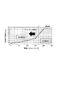
図15は、帯電ACのVppとカブリ量との関係を示すグラフ図である。図15の横軸は帯電ACのVpp(便宜上、放電開始電圧2Vthを差し引いた値を示している。)、縦軸はカブリ量である。図16は、図15に示す帯電ACのVppとカブリ量との関係が成り立つ場合における、実施例1と同様の供給量(12mg)を確保するために必要な帯電ACのVppと供給動作の時間との関係を示す。図16の横軸は帯電ACのVpp(便宜上、放電開始電圧2Vthを差し引いた値を示している。)、縦軸は供給動作の時間である。図16中の供給量12mgのラインよりも左側の領域は供給量過多の領域であり、右側の領域は供給量過少の領域である。 FIG. 15 is a graph showing the relationship between the Vpp of the charged AC and the amount of fog. The horizontal axis of FIG. 15 is the Vpp of the charged AC (for convenience, the value obtained by subtracting the discharge start voltage 2Vth), and the vertical axis is the amount of fog. FIG. 16 shows the Vpp of the charged AC and the time of the supply operation required to secure the same supply amount (12 mg) as in Example 1 when the relationship between the Vpp of the charged AC and the fog amount shown in FIG. 15 is established. Shows the relationship with. The horizontal axis of FIG. 16 is the Vpp of the charged AC (for convenience, the value obtained by subtracting the discharge start voltage 2Vth), and the vertical axis is the time of the supply operation. The region on the left side of the 12 mg supply line in FIG. 16 is the oversupply region, and the right side region is the undersupply region.
ここで、図15に示すように、カブリ量は帯電ACのVppが小さくなると急峻に立ち上がる。そして、その立ち上がり具合は、画像形成装置の状態、より詳細にはトナーの状態で変化し易い。そのため、このカブリ量が急峻に立ち上がる領域では、カブリ量の制御が難しい。そこで、カブリ量が急峻に上昇する直前の帯電ACのVppの値を閾値として、帯電ACのVppの下限を設定することで、カブリ量をコントロールし易くすることができる。つまり、図15から、制御の容易性の観点からは、供給動作における帯電ACのVpp1は、2Vth+50V≦Vpp1を満たすように設定することが好ましいことがわかる。 Here, as shown in FIG. 15, the amount of fog rises sharply when the Vpp of the charged AC becomes small. The rising state is likely to change depending on the state of the image forming apparatus, more specifically, the state of the toner. Therefore, it is difficult to control the amount of fog in the region where the amount of fog rises sharply. Therefore, it is possible to easily control the amount of fog by setting the lower limit of the Vpp of the charged AC with the value of Vpp of the charged AC immediately before the amount of fog rising sharply as a threshold value. That is, from FIG. 15, from the viewpoint of ease of control, it can be seen that it is preferable to set Vpp1 of the charged AC in the supply operation so as to satisfy 2Vth + 50V ≦ Vpp1.
一方、図16中の破線で示す値よりも帯電ACのVppが大きい場合には、カブリ量が少なくなるため、供給動作の時間を長くする必要がある。そこで、供給動作がダウンタイムに与える影響を十分に少なくできるように帯電ACのVppの上限を設定することで、ユーザーのメリットを向上することができる。例えば、供給動作の時間が500msec以下であれば、供給動作がダウンタイムに与える影響が少ないと見なせる。つまり、図16から、ユーザーのメッリト(ダウンタイムの低減)の観点からは、供給動作における帯電ACのVpp1は、Vpp1≦2Vth+170Vを満たすように設定することが好ましいことがわかる。 On the other hand, when the Vpp of the charged AC is larger than the value shown by the broken line in FIG. 16, the amount of fog is small, so that it is necessary to lengthen the supply operation time. Therefore, by setting the upper limit of the Vpp of the charged AC so that the influence of the supply operation on the downtime can be sufficiently reduced, the merit of the user can be improved. For example, if the supply operation time is 500 msec or less, it can be considered that the supply operation has little influence on the downtime. That is, from FIG. 16, it can be seen that from the viewpoint of user merits (reduction of downtime), it is preferable to set Vpp1 of the charged AC in the supply operation so as to satisfy Vpp1 ≦ 2Vth + 170V.
同様に、実施例6における単位面積当たりのカブリ量をコントロールするための手段であるバックコントラストに関して、制御の容易性、ユーザーのメリットの観点から上限、下限を設定することができる。図17は、バックコントラストとカブリ量との関係を示すグラフ図である。図17から、制御の容易性の観点からは、カブリ量が急峻に立ち上がる直前のバックコントラストの値を閾値として、10V≦|Vdc1−Vdev1|を満たすように供給動作におけるバックコントラストを設定することが好ましいことがわかる。また、図18は、図17に示すバックコントラストとカブリ量との関係が成り立つ場合における、実施例6と同様の供給量(12mg)を確保するために必要なバックコントラストと供給動作の時間との関係を示す。図18から、ユーザーのメリット(ダウンタイムの低減)の観点からは、500msecを閾値として、|Vdc1−Vdev1|≦70Vを満たすように供給動作におけるバックコントラストを設定することが好ましいことがわかる。 Similarly, with respect to the back contrast, which is a means for controlling the amount of fog per unit area in the sixth embodiment, the upper limit and the lower limit can be set from the viewpoint of ease of control and user's merit. FIG. 17 is a graph showing the relationship between the back contrast and the amount of fog. From FIG. 17, from the viewpoint of ease of control, the back contrast in the supply operation can be set so as to satisfy 10 V ≦ | Vdc1-Vdev1 | with the value of the back contrast immediately before the amount of fog rising sharply as a threshold value. It turns out to be preferable. Further, FIG. 18 shows the back contrast and the supply operation time required to secure the same supply amount (12 mg) as in Example 6 when the relationship between the back contrast and the fog amount shown in FIG. 17 is established. Show the relationship. From FIG. 18, it can be seen that from the viewpoint of user merit (reduction of downtime), it is preferable to set the back contrast in the supply operation so as to satisfy | Vdc1-Vdev1 | ≦ 70V with 500 msec as a threshold value.
[その他]
以上、本発明を具体的な実施例に即して説明したが、本発明は上述の実施例に限定されるものではない。
[others]
Although the present invention has been described above with reference to specific examples, the present invention is not limited to the above-mentioned examples.
供給動作において帯電ACのVppを小さくして砂地カブリを発生させる場合、供給動作を行う直前の感光ドラムの表面電位は画像形成可能領域の略全域で略0Vであることが好ましい。これは、帯電ACのVppを小さくして電位均し効果を低下させて砂地カブリを発生させる場合、画像形成時と同様の略均一の暗電位が形成されている感光ドラムの表面に対してVppを小さくしても、電位均し効果の低下が望めないからである。この観点から、供給動作を行う直前の感光ドラムの表面電位が画像形成可能領域の略全域で略0Vである前回転工程時(実施例1など)に供給動作を行うことが好ましい。ただし、感光ドラムの回転方向において転写位置の下流側かつ帯電位置の上流側の除電位置において感光ドラムの表面の電荷の少なくとも一部を除去する除電手段を設けてもよい。除電手段としては、例えば除電位置で感光ドラムに光を照射する前露光手段を用いることができる。そして、供給動作において砂地カブリを発生させる感光ドラム上の領域が帯電位置に到達する際の表面電位を、好ましくは画像形成可能領域の略全域で略0Vにする。これにより、砂地カブリを発生させるべき感光ドラム上の所定の領域が帯電位置を通過する際に、感光ドラムと帯電ローラとの間で放電が生じ、適度な帯電ムラを生じさせることができる。この場合、紙間工程(実施例4)、後回転工程(実施例5)に供給動作を実行する場合でも、より確実に十分な量のトナーを砂地カブリにより感光ドラムに付着させることができる。 When the Vpp of the charged AC is reduced in the supply operation to generate sand fog, the surface potential of the photosensitive drum immediately before the supply operation is preferably approximately 0 V over substantially the entire image-forming region. This is because when the Vpp of the charged AC is reduced to reduce the potential leveling effect and sand fog is generated, Vpp is applied to the surface of the photosensitive drum in which a substantially uniform dark potential similar to that at the time of image formation is formed. This is because even if the value is reduced, the potential leveling effect cannot be expected to decrease. From this point of view, it is preferable to perform the supply operation during the pre-rotation step (Example 1 or the like) in which the surface potential of the photosensitive drum immediately before the supply operation is approximately 0 V in substantially the entire image-forming region. However, a static elimination means for removing at least a part of the charge on the surface of the photosensitive drum may be provided at the static elimination position on the downstream side of the transfer position and the upstream side of the charging position in the rotation direction of the photosensitive drum. As the static elimination means, for example, a pre-exposure means for irradiating the photosensitive drum with light at the static elimination position can be used. Then, the surface potential when the region on the photosensitive drum that generates sand fog in the supply operation reaches the charged position is preferably set to about 0 V over substantially the entire image-forming region. As a result, when a predetermined region on the photosensitive drum on which sand fog should be generated passes through the charging position, a discharge is generated between the photosensitive drum and the charging roller, and appropriate charging unevenness can be generated. In this case, even when the supply operation is executed in the paper-to-paper process (Example 4) and the post-rotation process (Example 5), a sufficient amount of toner can be more reliably adhered to the photosensitive drum by sand fog.
また、放電開始電圧2Vthは、画像形成装置の設置環境、あるいは繰り返し使用による帯電ローラの電気抵抗値の変化や感光ドラムの膜厚の変化などの種々の要因に応じて変化することがある。ここで、画像形成装置の設置環境は、例えば温度又は湿度(相対湿度あるいは絶対水分量)の少なくとも一方である。したがって、上述のVpp1の範囲は、画像形成装置が使用され得る任意の環境において十分に上述の範囲を満たすように予め設定しておくことができる。あるいは、種々の要因に応じて変化する放電開始電圧2Vthの特性を予め実験などによって求めておき、画像形成や供給動作に先立ってその特性に基づいて放電開始電圧2Vthを予測することができる。そして、画像形成時や供給動作時には、その予測される放電開始電圧2Vthに応じて変更した帯電ACのVpp(供給動作時のVpp1は予測した2Vthに対し上述の範囲を満たすようにする。)を用いることができる。さらに、画像形成装置において、帯電ローラに複数の試験電圧を印加した時の電流を測定して電流電圧特性を求め、その特性から放電開始電圧2Vthを求めることができる。典型的には、放電開始電圧2Vthより小さい少なくとも1点の電圧と、放電開始電圧2Vthより大きい少なくとも1点の電圧とを印加して、それぞれの電圧を印加した際に帯電電源に流れる電流を測定する。これにより、図4に示すような電流電圧特性を得ることができる。そして、例えば得られた特性の変曲点(概略、放電開始電圧2Vthより大きい電圧範囲における電流電圧特性を示す特性において、放電電流量が0μAの場合のVppに相当する。)から放電開始電圧2Vthを求めることができる。この放電開始電圧2Vthを求める動作は、所定のタイミングで非画像形成時に行うことができる。上記所定のタイミングは、環境(温度又は湿度の少なくとも一方)が所定の範囲以上に変化した場合、帯電ローラ又は感光ドラムの使用量と相関する指標値が所定の閾値を超えた場合などとすることができる。また、帯電ローラ又は感光ドラムの使用量と相関する指標値としては、回転回数、回転時間、帯電処理を行った時間、画像形成枚数などの任意の値を利用できる。 Further, the discharge start voltage 2Vth may change depending on various factors such as the installation environment of the image forming apparatus, the change in the electric resistance value of the charging roller due to repeated use, and the change in the film thickness of the photosensitive drum. Here, the installation environment of the image forming apparatus is, for example, at least one of temperature and humidity (relative humidity or absolute water content). Therefore, the above-mentioned range of Vpp1 can be preset so as to sufficiently satisfy the above-mentioned range in any environment in which the image forming apparatus can be used. Alternatively, the characteristics of the discharge start voltage 2Vth that change according to various factors can be obtained in advance by experiments or the like, and the discharge start voltage 2Vth can be predicted based on the characteristics prior to the image formation or the supply operation. Then, at the time of image formation or supply operation, the Vpp of the charged AC changed according to the predicted discharge start voltage 2Vth (Vpp1 at the time of supply operation satisfies the above range with respect to the predicted 2Vth). Can be used. Further, in the image forming apparatus, the current-voltage characteristic can be obtained by measuring the current when a plurality of test voltages are applied to the charging roller, and the discharge start voltage 2Vth can be obtained from the characteristic. Typically, a voltage at at least one point smaller than the discharge start voltage of 2 Vth and a voltage at at least one point larger than the discharge start voltage of 2 Vth are applied, and the current flowing through the charged power supply when each voltage is applied is measured. do. As a result, the current-voltage characteristics as shown in FIG. 4 can be obtained. Then, for example, from the inflection point of the obtained characteristics (generally, in the characteristics showing the current-voltage characteristics in the voltage range larger than the discharge start voltage 2Vth, it corresponds to Vpp when the discharge current amount is 0 μA), the discharge start voltage 2Vth. Can be asked. This operation of obtaining the discharge start voltage 2Vth can be performed at a predetermined timing during non-image formation. The predetermined timing is when the environment (at least one of temperature or humidity) changes to a predetermined range or more, or when the index value correlating with the usage amount of the charging roller or the photosensitive drum exceeds a predetermined threshold value. Can be done. Further, as an index value that correlates with the amount of the charging roller or the photosensitive drum, any value such as the number of rotations, the rotation time, the time of performing the charging process, and the number of images formed can be used.
また、上述の実施例では、単色の画像形成装置の例を説明したが、本発明はカラー画像形成装置にも適用できるものである。例えば、複数の感光ドラムにそれぞれ異なる色のトナー像を形成し、各色のトナー像を中間転写体に順次一次転写した後に記録材に二次転写する中間転写方式や、記録材担持体に担持された記録材に順次転写する直接転写方式のカラー画像形成装置が周知である。これらの画像形成装置では、各感光ドラムに対応して、上述の実施例のものと同様の帯電ローラ、現像装置、転写ローラ(一次転写ローラ)、クリーニング装置などが設けられる。 Further, in the above-described embodiment, an example of a monochromatic image forming apparatus has been described, but the present invention can also be applied to a color image forming apparatus. For example, an intermediate transfer method in which toner images of different colors are formed on a plurality of photosensitive drums, the toner images of each color are sequentially transferred to an intermediate transfer body and then secondarily transferred to a recording material, or the toner images are supported on a recording material carrier. A direct transfer type color image forming apparatus that sequentially transfers to a recording material is well known. In these image forming devices, a charging roller, a developing device, a transfer roller (primary transfer roller), a cleaning device, and the like similar to those in the above-described embodiment are provided corresponding to each photosensitive drum.
また、上述の実施例では、電荷の絶対値が相対的に小さいカブリを起こしたトナーを、転写位置を通過させてクリーニング位置に供給するために、転写ローラに該トナーと同極性の電圧を印加した。別法として、該トナーが転写位置を通過する際に感光ドラムから転写ローラ(あるいは中間転写体や記録材担持体)を離間させてもよい。 Further, in the above-described embodiment, in order to supply the fogged toner having a relatively small absolute value of electric charge to the cleaning position through the transfer position, a voltage having the same polarity as the toner is applied to the transfer roller. bottom. Alternatively, the transfer roller (or intermediate transfer body or recording material carrier) may be separated from the photosensitive drum as the toner passes through the transfer position.
また、本発明は、クリーニング部材としてクリーニングブレードが用いられる場合に好ましく適用できるものである。ただし、感光ドラムに当接させて配置するクリーニング部材であって、感光ドラムとの間の摩擦力の上昇によるクリーニング不良の発生が懸念されるクリーニング部材が用いる場合には、本発明を適用することで上述の実施例と同様の効果が期待できる。 Further, the present invention is preferably applicable when a cleaning blade is used as a cleaning member. However, the present invention shall be applied when a cleaning member that is placed in contact with the photosensitive drum and is concerned about the occurrence of cleaning defects due to an increase in frictional force with the photosensitive drum is used. The same effect as that of the above-mentioned embodiment can be expected.
また、上述の実施例では、帯電部材が被帯電体である感光ドラムの表面に接触している場合を例に説明したが、帯電部材は必ずしも感光ドラムの表面に接触している必要はない。帯電部材と感光ドラムとの間にパッシェンの法則に基づく放電可能領域が設けられていれば、例えば数10μmの空隙(間隙)を有して非接触に近接配置されていてもよい。 Further, in the above-described embodiment, the case where the charged member is in contact with the surface of the photosensitive drum, which is the charged body, has been described as an example, but the charged member does not necessarily have to be in contact with the surface of the photosensitive drum. As long as a dischargeable region based on Paschen's law is provided between the charging member and the photosensitive drum, it may be arranged in close proximity to each other with a gap (gap) of, for example, several tens of μm.
また、帯電部材はローラ状の部材に限定されるものではなく、複数の張架ローラに張架された無端状のベルトやブレード状の部材であってもよい。また、像担持体はドラム状の感光体(感光ドラム)に限定されるものではなく、無端ベルト状の感光体(感光体ベルト)であってもよい。静電記録方式の画像形成装置であれば、像担持体はドラム状や無端ベルト状の静電記録誘電体であってよい。 Further, the charging member is not limited to the roller-shaped member, and may be an endless belt or a blade-shaped member stretched on a plurality of tension rollers. Further, the image carrier is not limited to the drum-shaped photoconductor (photosensitive drum), and may be an endless belt-shaped photoconductor (photoreceptor belt). In the case of an electrostatic recording type image forming apparatus, the image carrier may be a drum-shaped or endless belt-shaped electrostatic recording dielectric.
1 感光ドラム(像担持体)
2 帯電ローラ(帯電部材)
4 現像装置
5 転写ローラ(転写部材)
6 クリーニング装置
41 現像スリーブ(現像部材)
61 クリーニングブレード(クリーニング部材)
1 Photosensitive drum (image carrier)
2 Charging roller (charging member)
4
6
61 Cleaning blade (cleaning member)
Claims (19)
前記像担持体の表面を帯電させる帯電部材と、
直流成分と交流成分とが重畳された帯電電圧を前記帯電部材に印加する帯電電源と、
帯電した前記像担持体上に静電像を形成する静電像形成手段と、
前記像担持体上に形成された前記静電像にトナーを供給して前記トナー像を形成する現像部材と、
現像電圧を前記現像部材に印加する現像電源と、
前記像担持体上に形成された前記トナー像を転写位置で被転写体に転写させる転写手段と、
前記像担持体の回転方向において前記転写位置より下流側かつ前記帯電部材との当接位置より上流側で前記像担持体に当接し、前記像担持体上から前記トナーを除去するクリーニング部材と、
非画像形成時に、前記トナーを前記クリーニング部材に供給する供給動作を実行するために、前記トナーを移動させるための前記帯電電圧、前記現像電圧をそれぞれ前記帯電部材と前記現像部材に印加させることが可能な制御部と、
を有し、
前記供給動作の実行時に印加する前記帯電電圧の前記交流成分のピーク間電圧をVpp1(V)とすると、画像形成時に印加する前記帯電電圧の前記交流成分のピーク間電圧は、前記Vpp1(V)より大きく、前記像担持体と前記帯電部材との間の前記直流成分の放電開始電圧をVth(V)とすると、
前記制御部は、前記供給動作を実行するために、次式、
2Vth(V)≦Vpp1(V)≦(2Vth+200)(V)
を満たす前記Vpp1(V)を前記帯電部材に印加するように制御を行い、かつ、
前記制御部は、前記非画像形成時に、前記帯電電圧の前記交流成分のピーク間電圧の切り替えを行うことが可能であり、前記画像形成時に印加する前記帯電電圧の前記交流成分のピーク間電圧をVpp2(V)、前記帯電部材に前記Vpp1(V)が印加され電位が形成される前記像担持体上の領域とは別の前記像担持体上の領域が、前記帯電部材との当接位置を通過する際の前記帯電電圧の前記交流成分のピーク間電圧をVpp3(V)としたとき、次式、
Vpp1(V)<Vpp3(V)<Vpp2(V)
を満たすように前記切り替えの制御を行うことを特徴とする画像形成装置。 A rotatable image carrier that supports the toner image and
A charging member that charges the surface of the image carrier, and
A charging power supply that applies a charging voltage on which a DC component and an AC component are superimposed to the charging member, and
An electrostatic image forming means for forming an electrostatic image on the charged image carrier, and
A developing member that supplies toner to the electrostatic image formed on the image carrier to form the toner image, and
A developing power source that applies a developing voltage to the developing member,
A transfer means for transferring the toner image formed on the image carrier to the transfer target at the transfer position, and a transfer means.
A cleaning member that abuts on the image carrier on the downstream side of the transfer position and upstream of the contact position with the charging member in the rotation direction of the image carrier and removes the toner from the image carrier.
At the time of non-image formation, in order to execute the supply operation of supplying the toner to the cleaning member, the charging voltage and the developing voltage for moving the toner may be applied to the charging member and the developing member, respectively. Possible controls and
Have,
Assuming that the peak voltage of the AC component of the charging voltage applied at the time of executing the supply operation is Vpp1 (V), the peak voltage of the AC component of the charging voltage applied at the time of image formation is Vpp1 (V). Larger, assuming that the discharge start voltage of the DC component between the image carrier and the charging member is Vth (V).
In order to execute the supply operation, the control unit has the following equation:
2Vth (V) ≤ Vpp1 (V) ≤ (2Vth + 200) (V)
There line control so as to apply to said charging member said Vpp1 the (V) satisfying, and
The control unit can switch the peak-to-peak voltage of the AC component of the charging voltage at the time of non-image formation, and can change the peak-to-peak voltage of the AC component of the charging voltage applied at the time of image formation. Vpp2 (V), a region on the image carrier different from the region on the image carrier on which the Vpp1 (V) is applied to the charging member to form a potential is the contact position with the charging member. When the peak voltage of the AC component of the charging voltage when passing through is Vpp3 (V), the following equation,
Vpp1 (V) <Vpp3 (V) <Vpp2 (V)
An image forming apparatus, characterized in that the switching is controlled so as to satisfy the above conditions.
(2Vth+50)(V)≦Vpp1(V)≦(2Vth+170)(V)
を満たすことを特徴とする請求項1に記載の画像形成装置。 The Vpp1 (V) is expressed by the following equation:
(2Vth + 50) (V) ≤ Vpp1 (V) ≤ (2Vth + 170) (V)
The image forming apparatus according to claim 1 , wherein the image forming apparatus satisfies the above conditions.
前記像担持体の表面を帯電させる帯電部材と、
直流成分と交流成分とが重畳された帯電電圧を前記帯電部材に印加する帯電電源と、
帯電した前記像担持体上に静電像を形成する静電像形成手段と、
前記像担持体上に形成された前記静電像にトナーを供給して前記トナー像を形成する現像部材と、
少なくとも直流成分を含む現像電圧を前記現像部材に印加する現像電源と、
前記像担持体上に形成された前記トナー像を転写位置で被転写体に転写させる転写手段と、
前記像担持体の回転方向において前記転写位置より下流側かつ前記帯電部材との当接位置より上流側で前記像担持体に当接し、前記像担持体上から前記トナーを除去するクリーニング部材と、
非画像形成時に、前記トナーを前記クリーニング部材に供給する供給動作を実行するために、前記現像部材から前記像担持体上に前記トナーを移動させるための前記帯電電圧、前記現像電圧をそれぞれ前記帯電部材と前記現像部材に印加させることが可能な制御部と、を有し、
前記供給動作の実行時に印加する前記帯電電圧の前記直流成分をVdc1(V)、画像形成時に印加する前記帯電電圧の前記直流成分をVdc2(V)、前記供給動作の実行時に印加する前記現像電圧の前記直流成分をVdev1(V)、前記画像形成時に印加する前記現像電圧の前記直流成分をVdev2(V)とすると、
前記制御部は、次式、
0(V)<|Vdc1−Vdev1|(V)<|Vdc2−Vdev2|(V)
を満たす前記帯電電圧、前記現像電圧を、それぞれ前記帯電部材、前記現像部材に印加する前記供給動作を実行するように制御を行い、かつ、
前記制御部は、前記非画像形成時に、前記帯電電圧の前記直流成分と前記現像電圧の前記直流成分との差分の切り替えを行うことが可能であり、前記帯電部材に前記Vdc1(V)が印加され電位が形成される前記像担持体上の領域とは別の前記像担持体上の領域が、前記帯電部材との当接位置を通過する際に前記帯電部材に印加される前記帯電電圧の前記直流成分をVdc3(V)、前記別の前記像担持体上の領域が前記現像部材との当接位置を通過する際に前記現像部材に印加される前記現像電圧の前記直流成分をVdev3(V)としたとき、次式、
|Vdc1−Vdev1|(V)<|Vdc3−Vdev3|(V)<|Vdc2−Vdev2|(V)
を満たすように前記切り替えの制御を行うことを特徴とする画像形成装置。 A rotatable image carrier that supports the toner image and
A charging member that charges the surface of the image carrier, and
A charging power supply that applies a charging voltage on which a DC component and an AC component are superimposed to the charging member, and
An electrostatic image forming means for forming an electrostatic image on the charged image carrier, and
A developing member that supplies toner to the electrostatic image formed on the image carrier to form the toner image, and
A developing power source that applies a developing voltage containing at least a DC component to the developing member, and
A transfer means for transferring the toner image formed on the image carrier to the transfer target at the transfer position, and a transfer means.
A cleaning member that abuts on the image carrier on the downstream side of the transfer position and upstream of the contact position with the charging member in the rotation direction of the image carrier and removes the toner from the image carrier.
At the time of non-image formation, in order to execute the supply operation of supplying the toner to the cleaning member, the charging voltage for moving the toner from the developing member onto the image carrier and the developing voltage are charged respectively. It has a member and a control unit that can be applied to the developing member.
The DC component of the charging voltage applied at the time of executing the supply operation is Vdc1 (V), the DC component of the charging voltage applied at the time of image formation is Vdc2 (V), and the development voltage applied at the time of executing the supply operation. Let Vdev1 (V) be the DC component of the above, and Vdev2 (V) be the DC component of the development voltage applied at the time of image formation.
The control unit has the following equation:
0 (V) << Vdc1-Vdev1 | (V) << Vdc2-Vdev2 | (V)
The charging voltage satisfying, the developing voltage, each of said charging member, have row control to perform the supply operation to be applied to said developing member, and,
The control unit can switch the difference between the DC component of the charging voltage and the DC component of the developing voltage at the time of non-image formation, and the Vdc1 (V) is applied to the charging member. A region on the image carrier that is different from the region on the image carrier on which the potential is formed is the charging voltage applied to the charging member when the region on the image carrier passes through the contact position with the charging member. The DC component is Vdc3 (V), and the DC component of the development voltage applied to the developing member when the other region on the image carrier passes through the contact position with the developing member is Vdev3 (Vdev3 (V). When V) is set, the following equation,
| Vdc1-Vdev1 | (V) << Vdc3-Vdev3 | (V) << Vdc2-Vdev2 | (V)
An image forming apparatus, characterized in that the switching is controlled so as to satisfy the above conditions.
10(V)≦|Vdc1−Vdev1|(V)≦(|Vdc2−Vdev2|−30)(V)
を満たすことを特徴とする請求項3に記載の画像形成装置。 The | Vdc1-Vdev1 | (V) is expressed by the following equation.
10 (V) ≤ | Vdc1-Vdev1 | (V) ≤ (| Vdc2-Vdev2 | -30) (V)
The image forming apparatus according to claim 3 , wherein the image forming apparatus satisfies the above conditions.
前記制御部は、前記帯電部材に前記Vpp1(V)が印加され電位が形成される前記像担持体上の領域が前記転写位置を通過する際に前記転写手段に前記画像形成時とは逆極性の電圧を印加するように制御を行うことを特徴とする請求項1又は2に記載の画像形成装置。 It has a transfer power supply that applies a DC voltage to the transfer means, and has a transfer power supply.
When the region on the image carrier on which the Vpp1 (V) is applied to the charging member and the potential is formed passes through the transfer position, the control unit causes the transfer means to have the opposite polarity to that at the time of image formation. The image forming apparatus according to claim 1 or 2 , wherein the image forming apparatus is controlled so as to apply the voltage of the above.
前記制御部は、前記計数手段の計数結果が閾値以上の場合に、前記非画像形成時に前記供給動作を実行するように制御を行うことを特徴とする請求項1〜8のいずれか一項に記載の画像形成装置。 It has a counting means for counting an index value having a positive correlation with the moving distance in the rotation direction of the image carrier.
The control unit according to any one of claims 1 to 8 , wherein the control unit controls to execute the supply operation at the time of non-image formation when the counting result of the counting means is equal to or higher than the threshold value. The image forming apparatus according to the description.
前記制御部は、前記温度検知手段により検知された温度が第1の温度の場合の前記閾値よりも、前記温度検知手段により検知された温度が前記第1の温度よりも高い第2の温度の場合の前記閾値を大きくするように、前記温度検知手段の検知結果に応じて前記閾値を変更することを特徴とする請求項10又は11に記載の画像形成装置。 It has a temperature detecting means for detecting the temperature inside or outside the main body of the image forming apparatus.
The control unit has a second temperature at which the temperature detected by the temperature detecting means is higher than the threshold value when the temperature detected by the temperature detecting means is the first temperature. The image forming apparatus according to claim 10 or 11 , wherein the threshold value is changed according to the detection result of the temperature detecting means so as to increase the threshold value in the case.
前記現像装置の使用量と正の相関を有する指標値を計数する使用量計数手段と、
を有し、
前記制御部は、前記使用量計数手段の計数結果が第1の値の場合の前記閾値よりも、前記使用量計数手段の計数結果が前記第1の値よりも大きい第2の値の場合の前記閾値を小さくするように、前記使用量計数手段の計数結果に応じて前記閾値を変更することを特徴とする請求項10又は11に記載の画像形成装置。 A developing apparatus including the developing member and a developing container for accommodating the toner.
A usage counting means for counting an index value having a positive correlation with the usage of the developing device,
Have,
The control unit has a second value in which the counting result of the usage counting means is larger than the threshold value in the case of the first value and the counting result of the usage counting means is larger than the first value. The image forming apparatus according to claim 10 or 11 , wherein the threshold value is changed according to the counting result of the usage amount counting means so as to reduce the threshold value.
前記制御部は、前記計数手段の計数結果が閾値以下の場合に、前記非画像形成時に前記供給動作を実行するように制御を行うことを特徴とする請求項1〜8のいずれか一項に記載の画像形成装置。 It has a counting means for counting an index value having a positive correlation with the amount of the toner supplied to the image carrier while the image carrier moves by a predetermined distance in the rotation direction.
The control unit according to any one of claims 1 to 8 , wherein the control unit controls to execute the supply operation at the time of non-image formation when the counting result of the counting means is equal to or less than the threshold value. The image forming apparatus according to the description.
前記制御部は、前記温度検知手段により検知された温度が第1の温度の場合の前記閾値よりも、前記温度検知手段により検知された温度が前記第1の温度よりも高い第2の温度の場合の前記閾値を小さくするように、前記温度検知手段の検知結果に応じて前記閾値を変更することを特徴とする請求項14に記載の画像形成装置。 It has a temperature detecting means for detecting the temperature inside or outside the main body of the image forming apparatus.
The control unit has a second temperature at which the temperature detected by the temperature detecting means is higher than the threshold value when the temperature detected by the temperature detecting means is the first temperature. The image forming apparatus according to claim 14 , wherein the threshold value is changed according to the detection result of the temperature detecting means so as to reduce the threshold value in the case.
前記現像装置の使用量と正の相関を有する指標値を計数する使用量計数手段と、
を有し、
前記制御部は、前記使用量計数手段の計数結果が第1の値の場合の前記閾値よりも、前記使用量計数手段の計数結果が前記第1の値よりも大きい第2の値の場合の前記閾値を大きくするように、前記使用量計数手段の計数結果に応じて前記閾値を変更することを特徴とする請求項14に記載の画像形成装置。 A developing apparatus including the developing member and a developing container for accommodating the toner.
A usage counting means for counting an index value having a positive correlation with the usage of the developing device,
Have,
The control unit has a second value in which the counting result of the usage counting means is larger than the threshold value in the case of the first value and the counting result of the usage counting means is larger than the first value. The image forming apparatus according to claim 14 , wherein the threshold value is changed according to the counting result of the usage amount counting means so as to increase the threshold value.
前記制御部は、前記温度検知手段により検知された温度が閾値以下の場合に、前記非画像形成時に前記供給動作を実行するように制御を行うことを特徴とする請求項1〜8のいずれか一項に記載の画像形成装置。 It has a temperature detecting means for detecting the temperature inside or outside the main body of the image forming apparatus.
One of claims 1 to 8 , wherein the control unit controls to execute the supply operation at the time of non-image formation when the temperature detected by the temperature detecting means is equal to or less than a threshold value. The image forming apparatus according to one item.
前記現像装置の使用量と正の相関を有する指標値を計数する使用量計数手段と、
を有し、
前記制御部は、前記使用量計数手段の計数結果が閾値以上の場合に、前記非画像形成時に前記供給動作を実行するように制御を行うことを特徴とする請求項1〜8のいずれか一項に記載の画像形成装置。 A developing apparatus including the developing member and a developing container for accommodating the toner.
A usage counting means for counting an index value having a positive correlation with the usage of the developing device,
Have,
One of claims 1 to 8 , wherein the control unit controls to execute the supply operation at the time of non-image formation when the counting result of the usage counting means is equal to or higher than the threshold value. The image forming apparatus according to the section.
前記制御部は、前記トルク検知手段の検知結果が閾値以上の場合に、前記非画像形成時に前記供給動作を実行するように制御を行うことを特徴とする請求項1〜8のいずれか一項に記載の画像形成装置。 It has a torque detecting means for detecting an index value having a positive correlation with the rotational torque of the drive motor that drives the image carrier.
One of claims 1 to 8 , wherein the control unit controls to execute the supply operation at the time of non-image formation when the detection result of the torque detecting means is equal to or higher than a threshold value. The image forming apparatus according to.
Priority Applications (2)
| Application Number | Priority Date | Filing Date | Title |
|---|---|---|---|
| JP2017104005A JP6971632B2 (en) | 2017-05-25 | 2017-05-25 | Image forming device |
| US15/988,290 US10444656B2 (en) | 2017-05-25 | 2018-05-24 | Image forming apparatus |
Applications Claiming Priority (1)
| Application Number | Priority Date | Filing Date | Title |
|---|---|---|---|
| JP2017104005A JP6971632B2 (en) | 2017-05-25 | 2017-05-25 | Image forming device |
Publications (3)
| Publication Number | Publication Date |
|---|---|
| JP2018200351A JP2018200351A (en) | 2018-12-20 |
| JP2018200351A5 JP2018200351A5 (en) | 2020-07-02 |
| JP6971632B2 true JP6971632B2 (en) | 2021-11-24 |
Family
ID=64401571
Family Applications (1)
| Application Number | Title | Priority Date | Filing Date |
|---|---|---|---|
| JP2017104005A Active JP6971632B2 (en) | 2017-05-25 | 2017-05-25 | Image forming device |
Country Status (2)
| Country | Link |
|---|---|
| US (1) | US10444656B2 (en) |
| JP (1) | JP6971632B2 (en) |
Families Citing this family (4)
| Publication number | Priority date | Publication date | Assignee | Title |
|---|---|---|---|---|
| JP7098339B2 (en) * | 2018-01-24 | 2022-07-11 | キヤノン株式会社 | Image forming device |
| US11513449B2 (en) * | 2019-12-04 | 2022-11-29 | Canon Kabushiki Kaisha | Non-contact developer bias voltage control for image forming apparatus |
| JP2023026986A (en) * | 2021-08-16 | 2023-03-01 | キヤノン株式会社 | Image forming apparatus |
| JP2023044587A (en) * | 2021-09-17 | 2023-03-30 | キヤノン株式会社 | Image forming apparatus |
Family Cites Families (17)
| Publication number | Priority date | Publication date | Assignee | Title |
|---|---|---|---|---|
| JPH10161426A (en) * | 1996-12-05 | 1998-06-19 | Ricoh Co Ltd | Image forming device |
| JP2004170956A (en) * | 2002-11-08 | 2004-06-17 | Canon Inc | Image forming apparatus, cartridge, image forming system and memory medium for cartridge |
| JP4343612B2 (en) * | 2003-07-18 | 2009-10-14 | キヤノン株式会社 | Image forming apparatus |
| JP4984616B2 (en) * | 2006-04-11 | 2012-07-25 | 富士ゼロックス株式会社 | Image forming method |
| JP5126485B2 (en) * | 2007-06-15 | 2013-01-23 | 富士ゼロックス株式会社 | Image forming apparatus |
| US7917049B2 (en) * | 2008-06-10 | 2011-03-29 | Xerox Corporation | Variable interference cleaning blade method |
| JP5335384B2 (en) | 2008-11-19 | 2013-11-06 | キヤノン株式会社 | Image forming apparatus |
| JP5521420B2 (en) * | 2009-07-17 | 2014-06-11 | 富士ゼロックス株式会社 | Image forming apparatus |
| JP5473501B2 (en) | 2009-09-08 | 2014-04-16 | キヤノン株式会社 | Image forming apparatus |
| JP5447152B2 (en) * | 2010-04-28 | 2014-03-19 | コニカミノルタ株式会社 | Image forming apparatus and cleaning method |
| JP2012132948A (en) * | 2010-12-17 | 2012-07-12 | Canon Inc | Image forming device |
| JP2012189801A (en) * | 2011-03-10 | 2012-10-04 | Canon Inc | Image forming apparatus |
| JP6390590B2 (en) * | 2015-02-26 | 2018-09-19 | 京セラドキュメントソリューションズ株式会社 | Image forming apparatus |
| JP6548429B2 (en) * | 2015-03-31 | 2019-07-24 | キヤノン株式会社 | Image forming device |
| JP6332157B2 (en) * | 2015-06-18 | 2018-05-30 | 京セラドキュメントソリューションズ株式会社 | Image forming apparatus |
| JP2017009913A (en) * | 2015-06-25 | 2017-01-12 | キヤノン株式会社 | Image forming apparatus |
| JP2017021168A (en) * | 2015-07-10 | 2017-01-26 | キヤノン株式会社 | Image forming apparatus |
-
2017
- 2017-05-25 JP JP2017104005A patent/JP6971632B2/en active Active
-
2018
- 2018-05-24 US US15/988,290 patent/US10444656B2/en active Active
Also Published As
| Publication number | Publication date |
|---|---|
| US20180341192A1 (en) | 2018-11-29 |
| JP2018200351A (en) | 2018-12-20 |
| US10444656B2 (en) | 2019-10-15 |
Similar Documents
| Publication | Publication Date | Title |
|---|---|---|
| JP6971632B2 (en) | Image forming device | |
| JP5188339B2 (en) | Image forming apparatus | |
| US20190354044A1 (en) | Image forming apparatus | |
| US9665032B2 (en) | Image forming apparatus with exposure controlled in dependence on cumulative operating time and humidity | |
| JP5253487B2 (en) | Image forming apparatus | |
| JP5197264B2 (en) | Image forming apparatus | |
| US8787783B2 (en) | Image forming apparatus having voltage control | |
| JP2007086660A (en) | Image forming apparatus | |
| JP6995521B2 (en) | Image forming device | |
| JP2016206599A (en) | Image forming apparatus | |
| JP4193853B2 (en) | Developing device and image forming apparatus using the same | |
| JP2013171094A (en) | Image forming apparatus | |
| JP7013173B2 (en) | Image forming device | |
| JP7463193B2 (en) | Image forming device | |
| JP7027098B2 (en) | Image forming device | |
| JP3817930B2 (en) | Developing device and image forming apparatus using the same | |
| US10261462B2 (en) | Image forming apparatus | |
| JP7034653B2 (en) | Image forming device | |
| JP2010169887A (en) | Image forming apparatus | |
| JP2020139986A (en) | Image formation apparatus | |
| JP2020020920A (en) | Image forming device | |
| US11892791B2 (en) | Image forming apparatus | |
| JP2019128458A (en) | Image forming apparatus | |
| US20240103409A1 (en) | Image forming apparatus | |
| JP2004170827A (en) | Development device for image forming apparatus |
Legal Events
| Date | Code | Title | Description |
|---|---|---|---|
| A521 | Written amendment |
Free format text: JAPANESE INTERMEDIATE CODE: A523 Effective date: 20200520 |
|
| A621 | Written request for application examination |
Free format text: JAPANESE INTERMEDIATE CODE: A621 Effective date: 20200520 |
|
| A977 | Report on retrieval |
Free format text: JAPANESE INTERMEDIATE CODE: A971007 Effective date: 20210309 |
|
| A131 | Notification of reasons for refusal |
Free format text: JAPANESE INTERMEDIATE CODE: A131 Effective date: 20210406 |
|
| A521 | Written amendment |
Free format text: JAPANESE INTERMEDIATE CODE: A523 Effective date: 20210607 |
|
| TRDD | Decision of grant or rejection written | ||
| A01 | Written decision to grant a patent or to grant a registration (utility model) |
Free format text: JAPANESE INTERMEDIATE CODE: A01 Effective date: 20211005 |
|
| A61 | First payment of annual fees (during grant procedure) |
Free format text: JAPANESE INTERMEDIATE CODE: A61 Effective date: 20211102 |
|
| R151 | Written notification of patent or utility model registration |
Ref document number: 6971632 Country of ref document: JP Free format text: JAPANESE INTERMEDIATE CODE: R151 |