JP6971377B2 - Fluid discharge device with built-in cross-passage - Google Patents
Fluid discharge device with built-in cross-passage Download PDFInfo
- Publication number
- JP6971377B2 JP6971377B2 JP2020502713A JP2020502713A JP6971377B2 JP 6971377 B2 JP6971377 B2 JP 6971377B2 JP 2020502713 A JP2020502713 A JP 2020502713A JP 2020502713 A JP2020502713 A JP 2020502713A JP 6971377 B2 JP6971377 B2 JP 6971377B2
- Authority
- JP
- Japan
- Prior art keywords
- fluid
- built
- fluid discharge
- nozzle
- array
- Prior art date
- Legal status (The legal status is an assumption and is not a legal conclusion. Google has not performed a legal analysis and makes no representation as to the accuracy of the status listed.)
- Active
Links
- 239000012530 fluid Substances 0.000 title claims description 438
- 239000000758 substrate Substances 0.000 claims description 60
- 239000000463 material Substances 0.000 claims description 47
- 238000000034 method Methods 0.000 claims description 18
- 239000012528 membrane Substances 0.000 claims description 7
- 238000000465 moulding Methods 0.000 claims description 5
- 239000003086 colorant Substances 0.000 claims description 3
- 229920006336 epoxy molding compound Polymers 0.000 claims description 3
- 238000005530 etching Methods 0.000 claims description 2
- 238000007639 printing Methods 0.000 description 28
- 239000000976 ink Substances 0.000 description 16
- 238000010586 diagram Methods 0.000 description 11
- 238000007599 discharging Methods 0.000 description 9
- 239000003795 chemical substances by application Substances 0.000 description 6
- XUIMIQQOPSSXEZ-UHFFFAOYSA-N Silicon Chemical compound [Si] XUIMIQQOPSSXEZ-UHFFFAOYSA-N 0.000 description 5
- 230000004927 fusion Effects 0.000 description 5
- 238000004519 manufacturing process Methods 0.000 description 5
- 238000002156 mixing Methods 0.000 description 5
- 229910052710 silicon Inorganic materials 0.000 description 5
- 239000010703 silicon Substances 0.000 description 5
- XLYOFNOQVPJJNP-UHFFFAOYSA-N water Substances O XLYOFNOQVPJJNP-UHFFFAOYSA-N 0.000 description 5
- 238000002347 injection Methods 0.000 description 4
- 239000007924 injection Substances 0.000 description 4
- 239000000654 additive Substances 0.000 description 3
- 230000000996 additive effect Effects 0.000 description 3
- 230000002950 deficient Effects 0.000 description 3
- 239000002245 particle Substances 0.000 description 3
- 238000010146 3D printing Methods 0.000 description 2
- 230000015572 biosynthetic process Effects 0.000 description 2
- 239000004035 construction material Substances 0.000 description 2
- 238000001816 cooling Methods 0.000 description 2
- 230000007547 defect Effects 0.000 description 2
- 230000000694 effects Effects 0.000 description 2
- 238000012986 modification Methods 0.000 description 2
- 230000004048 modification Effects 0.000 description 2
- 239000000047 product Substances 0.000 description 2
- 235000001892 vitamin D2 Nutrition 0.000 description 2
- 239000002918 waste heat Substances 0.000 description 2
- RYGMFSIKBFXOCR-UHFFFAOYSA-N Copper Chemical compound [Cu] RYGMFSIKBFXOCR-UHFFFAOYSA-N 0.000 description 1
- 208000032400 Retinal pigmentation Diseases 0.000 description 1
- 238000009825 accumulation Methods 0.000 description 1
- 239000000853 adhesive Substances 0.000 description 1
- 230000001070 adhesive effect Effects 0.000 description 1
- 238000013459 approach Methods 0.000 description 1
- 230000006835 compression Effects 0.000 description 1
- 238000007906 compression Methods 0.000 description 1
- 229910052802 copper Inorganic materials 0.000 description 1
- 239000010949 copper Substances 0.000 description 1
- 230000008021 deposition Effects 0.000 description 1
- 230000001627 detrimental effect Effects 0.000 description 1
- 239000011521 glass Substances 0.000 description 1
- 238000007641 inkjet printing Methods 0.000 description 1
- 238000002032 lab-on-a-chip Methods 0.000 description 1
- 238000002844 melting Methods 0.000 description 1
- 230000008018 melting Effects 0.000 description 1
- 239000000203 mixture Substances 0.000 description 1
- 238000000206 photolithography Methods 0.000 description 1
- 239000000049 pigment Substances 0.000 description 1
- 239000004033 plastic Substances 0.000 description 1
- 229920000642 polymer Polymers 0.000 description 1
- 239000002244 precipitate Substances 0.000 description 1
- 238000012545 processing Methods 0.000 description 1
- 230000000541 pulsatile effect Effects 0.000 description 1
- 230000004044 response Effects 0.000 description 1
- 238000004062 sedimentation Methods 0.000 description 1
- 239000000243 solution Substances 0.000 description 1
- 239000000126 substance Substances 0.000 description 1
- 238000004448 titration Methods 0.000 description 1
- 238000012546 transfer Methods 0.000 description 1
Images


Classifications
-
- B—PERFORMING OPERATIONS; TRANSPORTING
- B41—PRINTING; LINING MACHINES; TYPEWRITERS; STAMPS
- B41J—TYPEWRITERS; SELECTIVE PRINTING MECHANISMS, i.e. MECHANISMS PRINTING OTHERWISE THAN FROM A FORME; CORRECTION OF TYPOGRAPHICAL ERRORS
- B41J2/00—Typewriters or selective printing mechanisms characterised by the printing or marking process for which they are designed
- B41J2/005—Typewriters or selective printing mechanisms characterised by the printing or marking process for which they are designed characterised by bringing liquid or particles selectively into contact with a printing material
- B41J2/01—Ink jet
- B41J2/135—Nozzles
- B41J2/16—Production of nozzles
- B41J2/1601—Production of bubble jet print heads
- B41J2/1603—Production of bubble jet print heads of the front shooter type
-
- B—PERFORMING OPERATIONS; TRANSPORTING
- B41—PRINTING; LINING MACHINES; TYPEWRITERS; STAMPS
- B41J—TYPEWRITERS; SELECTIVE PRINTING MECHANISMS, i.e. MECHANISMS PRINTING OTHERWISE THAN FROM A FORME; CORRECTION OF TYPOGRAPHICAL ERRORS
- B41J2/00—Typewriters or selective printing mechanisms characterised by the printing or marking process for which they are designed
- B41J2/005—Typewriters or selective printing mechanisms characterised by the printing or marking process for which they are designed characterised by bringing liquid or particles selectively into contact with a printing material
- B41J2/01—Ink jet
- B41J2/135—Nozzles
- B41J2/14—Structure thereof only for on-demand ink jet heads
- B41J2/14016—Structure of bubble jet print heads
- B41J2/14145—Structure of the manifold
-
- B—PERFORMING OPERATIONS; TRANSPORTING
- B41—PRINTING; LINING MACHINES; TYPEWRITERS; STAMPS
- B41J—TYPEWRITERS; SELECTIVE PRINTING MECHANISMS, i.e. MECHANISMS PRINTING OTHERWISE THAN FROM A FORME; CORRECTION OF TYPOGRAPHICAL ERRORS
- B41J2/00—Typewriters or selective printing mechanisms characterised by the printing or marking process for which they are designed
- B41J2/005—Typewriters or selective printing mechanisms characterised by the printing or marking process for which they are designed characterised by bringing liquid or particles selectively into contact with a printing material
- B41J2/01—Ink jet
- B41J2/135—Nozzles
- B41J2/14—Structure thereof only for on-demand ink jet heads
- B41J2/14201—Structure of print heads with piezoelectric elements
-
- B—PERFORMING OPERATIONS; TRANSPORTING
- B41—PRINTING; LINING MACHINES; TYPEWRITERS; STAMPS
- B41J—TYPEWRITERS; SELECTIVE PRINTING MECHANISMS, i.e. MECHANISMS PRINTING OTHERWISE THAN FROM A FORME; CORRECTION OF TYPOGRAPHICAL ERRORS
- B41J2/00—Typewriters or selective printing mechanisms characterised by the printing or marking process for which they are designed
- B41J2/005—Typewriters or selective printing mechanisms characterised by the printing or marking process for which they are designed characterised by bringing liquid or particles selectively into contact with a printing material
- B41J2/01—Ink jet
- B41J2/135—Nozzles
- B41J2/16—Production of nozzles
- B41J2/1601—Production of bubble jet print heads
-
- B—PERFORMING OPERATIONS; TRANSPORTING
- B41—PRINTING; LINING MACHINES; TYPEWRITERS; STAMPS
- B41J—TYPEWRITERS; SELECTIVE PRINTING MECHANISMS, i.e. MECHANISMS PRINTING OTHERWISE THAN FROM A FORME; CORRECTION OF TYPOGRAPHICAL ERRORS
- B41J2/00—Typewriters or selective printing mechanisms characterised by the printing or marking process for which they are designed
- B41J2/005—Typewriters or selective printing mechanisms characterised by the printing or marking process for which they are designed characterised by bringing liquid or particles selectively into contact with a printing material
- B41J2/01—Ink jet
- B41J2/135—Nozzles
- B41J2/16—Production of nozzles
- B41J2/1607—Production of print heads with piezoelectric elements
-
- B—PERFORMING OPERATIONS; TRANSPORTING
- B41—PRINTING; LINING MACHINES; TYPEWRITERS; STAMPS
- B41J—TYPEWRITERS; SELECTIVE PRINTING MECHANISMS, i.e. MECHANISMS PRINTING OTHERWISE THAN FROM A FORME; CORRECTION OF TYPOGRAPHICAL ERRORS
- B41J2/00—Typewriters or selective printing mechanisms characterised by the printing or marking process for which they are designed
- B41J2/005—Typewriters or selective printing mechanisms characterised by the printing or marking process for which they are designed characterised by bringing liquid or particles selectively into contact with a printing material
- B41J2/01—Ink jet
- B41J2/135—Nozzles
- B41J2/16—Production of nozzles
- B41J2/1621—Manufacturing processes
- B41J2/1623—Manufacturing processes bonding and adhesion
-
- B—PERFORMING OPERATIONS; TRANSPORTING
- B41—PRINTING; LINING MACHINES; TYPEWRITERS; STAMPS
- B41J—TYPEWRITERS; SELECTIVE PRINTING MECHANISMS, i.e. MECHANISMS PRINTING OTHERWISE THAN FROM A FORME; CORRECTION OF TYPOGRAPHICAL ERRORS
- B41J2/00—Typewriters or selective printing mechanisms characterised by the printing or marking process for which they are designed
- B41J2/005—Typewriters or selective printing mechanisms characterised by the printing or marking process for which they are designed characterised by bringing liquid or particles selectively into contact with a printing material
- B41J2/01—Ink jet
- B41J2/135—Nozzles
- B41J2/16—Production of nozzles
- B41J2/1621—Manufacturing processes
- B41J2/1626—Manufacturing processes etching
- B41J2/1628—Manufacturing processes etching dry etching
-
- B—PERFORMING OPERATIONS; TRANSPORTING
- B41—PRINTING; LINING MACHINES; TYPEWRITERS; STAMPS
- B41J—TYPEWRITERS; SELECTIVE PRINTING MECHANISMS, i.e. MECHANISMS PRINTING OTHERWISE THAN FROM A FORME; CORRECTION OF TYPOGRAPHICAL ERRORS
- B41J2/00—Typewriters or selective printing mechanisms characterised by the printing or marking process for which they are designed
- B41J2/005—Typewriters or selective printing mechanisms characterised by the printing or marking process for which they are designed characterised by bringing liquid or particles selectively into contact with a printing material
- B41J2/01—Ink jet
- B41J2/135—Nozzles
- B41J2/16—Production of nozzles
- B41J2/1621—Manufacturing processes
- B41J2/1637—Manufacturing processes molding
-
- B—PERFORMING OPERATIONS; TRANSPORTING
- B41—PRINTING; LINING MACHINES; TYPEWRITERS; STAMPS
- B41J—TYPEWRITERS; SELECTIVE PRINTING MECHANISMS, i.e. MECHANISMS PRINTING OTHERWISE THAN FROM A FORME; CORRECTION OF TYPOGRAPHICAL ERRORS
- B41J2/00—Typewriters or selective printing mechanisms characterised by the printing or marking process for which they are designed
- B41J2/005—Typewriters or selective printing mechanisms characterised by the printing or marking process for which they are designed characterised by bringing liquid or particles selectively into contact with a printing material
- B41J2/01—Ink jet
- B41J2/17—Ink jet characterised by ink handling
- B41J2/175—Ink supply systems ; Circuit parts therefor
-
- B—PERFORMING OPERATIONS; TRANSPORTING
- B41—PRINTING; LINING MACHINES; TYPEWRITERS; STAMPS
- B41J—TYPEWRITERS; SELECTIVE PRINTING MECHANISMS, i.e. MECHANISMS PRINTING OTHERWISE THAN FROM A FORME; CORRECTION OF TYPOGRAPHICAL ERRORS
- B41J2/00—Typewriters or selective printing mechanisms characterised by the printing or marking process for which they are designed
- B41J2/005—Typewriters or selective printing mechanisms characterised by the printing or marking process for which they are designed characterised by bringing liquid or particles selectively into contact with a printing material
- B41J2/01—Ink jet
- B41J2/135—Nozzles
- B41J2/14—Structure thereof only for on-demand ink jet heads
- B41J2002/14419—Manifold
-
- B—PERFORMING OPERATIONS; TRANSPORTING
- B41—PRINTING; LINING MACHINES; TYPEWRITERS; STAMPS
- B41J—TYPEWRITERS; SELECTIVE PRINTING MECHANISMS, i.e. MECHANISMS PRINTING OTHERWISE THAN FROM A FORME; CORRECTION OF TYPOGRAPHICAL ERRORS
- B41J2202/00—Embodiments of or processes related to ink-jet or thermal heads
- B41J2202/01—Embodiments of or processes related to ink-jet heads
- B41J2202/12—Embodiments of or processes related to ink-jet heads with ink circulating through the whole print head
-
- B—PERFORMING OPERATIONS; TRANSPORTING
- B41—PRINTING; LINING MACHINES; TYPEWRITERS; STAMPS
- B41J—TYPEWRITERS; SELECTIVE PRINTING MECHANISMS, i.e. MECHANISMS PRINTING OTHERWISE THAN FROM A FORME; CORRECTION OF TYPOGRAPHICAL ERRORS
- B41J2202/00—Embodiments of or processes related to ink-jet or thermal heads
- B41J2202/01—Embodiments of or processes related to ink-jet heads
- B41J2202/20—Modules
Landscapes
- Engineering & Computer Science (AREA)
- Manufacturing & Machinery (AREA)
- Particle Formation And Scattering Control In Inkjet Printers (AREA)
- Coating Apparatus (AREA)
- Ink Jet (AREA)
Description
流体吐出ダイは、流体吐出システムの部品であり、多数の流体吐出ノズルを含んでいる。流体ダイはまた、微小再循環ポンプのような、他の非吐出型アクチュエータを含むことができる。これらのノズルおよびポンプを通じて、流体、中でもインクおよび融合(溶融)剤が吐出または移動される。例えば、ノズルは所定量の流体を保持する吐出チャンバを含んでいてよく、吐出チャンバ内の流体アクチュエータが動作して、流体をノズルの開口を通して吐出する。流体吐出ダイおよび周囲のパッケージは、流体吐出デバイスとして参照されてよい。 The fluid discharge die is a component of the fluid discharge system and includes a large number of fluid discharge nozzles. The fluid die can also include other non-discharge actuators, such as microrecirculation pumps. Through these nozzles and pumps, fluids, especially inks and fusion (melting) agents, are ejected or moved. For example, the nozzle may include a discharge chamber that holds a predetermined amount of fluid, and a fluid actuator in the discharge chamber operates to discharge the fluid through the opening of the nozzle. The fluid discharge die and surrounding packages may be referred to as a fluid discharge device.
添付の図面は、本願に記載された原理の種々の例を図解しており、明細書の一部をなしている。図解された例は単に例示のために与えられたものであり、特許請求の範囲を制限するものではない。 The accompanying drawings illustrate various examples of the principles described herein and form part of the specification. The illustrated examples are given for illustration purposes only and do not limit the scope of the claims.
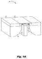
図1Aおよび図1Bは、本願に記載された原理の例に従う、内蔵された横断流路を備えた流体吐出ダイを有する流体吐出デバイスの等測図である。 1A and 1B are isometric views of a fluid discharge device with a fluid discharge die with a built-in transverse flow path, according to an example of the principles described herein.
図2Aから図2Dは、本願に記載された原理の例に従う、内蔵された横断流路を備えた流体吐出ダイの図面である。 2A-2D are drawings of a fluid discharge die with a built-in cross-passage according to an example of the principles described herein.
図3は、本願に記載された原理の例に従う、内蔵された横断流路を備えた流体吐出ダイの断面図である。 FIG. 3 is a cross-sectional view of a fluid discharge die with a built-in cross-passage according to an example of the principles described herein.
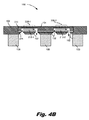
図4Aおよび図4Bは、本願に記載された原理の例に従う、内蔵された横断流路を備えた流体吐出ダイを有する流体吐出デバイスの断面図である。 4A and 4B are cross-sectional views of a fluid discharge device having a fluid discharge die with a built-in transverse flow path, according to an example of the principles described herein.
図5は、本願に記載された原理の例に従う、内蔵された横断流路を備えた流体吐出ダイの下側の等測図である。 FIG. 5 is an isometric view of the underside of a fluid discharge die with a built-in cross-passage according to an example of the principles described herein.
図6は、本願に記載された原理の例に従う、内蔵された横断流路を備えた流体吐出ダイを含む、印刷流体カートリッジのブロック図である。 FIG. 6 is a block diagram of a printing fluid cartridge comprising a fluid discharge die with a built-in cross-passage according to an example of the principles described herein.
図7は、本願に記載された原理の例に従う、基材幅の印刷バー内に内蔵された横断流路を備えた多数の流体吐出ダイを含んでいる印刷デバイスのブロック図である。 FIG. 7 is a block diagram of a printing device comprising a large number of fluid discharge dies with a cross-passage built into a substrate-width printing bar, according to an example of the principles described herein.
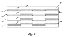
図8は、本願に記載された原理の例に従う、内蔵された横断流路を備えた多数の流体吐出ダイを含んでいる流体吐出ダイのブロック図である。 FIG. 8 is a block diagram of a fluid discharge die comprising a large number of fluid discharge dies with a built-in cross-passage according to an example of the principles described herein.
図9は、本願に記載された原理の例に従う、内蔵された横断流路を備えた流体吐出ダイを形成するための方法の流れ図である。 FIG. 9 is a flow diagram of a method for forming a fluid discharge die with a built-in transverse flow path, according to an example of the principles described herein.
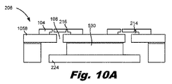
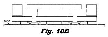
図10Aから図10Dは、本願に記載された原理の例に従う、内蔵された横断流路を備えた流体吐出ダイを製造するための方法を示している。 FIGS. 10A-10D show a method for manufacturing a fluid discharge die with a built-in cross-passage according to an example of the principles described herein.
図面を通じて、同一の参照番号は類似した、しかし必ずしも同一ではない要素を指定している。図面は必ずしも縮尺通りではなく、幾つかの部品の大きさは誇張されて、示された例をより明確に図解するようにされていてよい。さらにまた、図面は詳細な説明と矛盾のない例および/または実施態様を提示している;しかしながら、詳細な説明は図面に提示された例および/または実施態様に限定されるものではない。 Throughout the drawings, the same reference numbers specify elements that are similar, but not necessarily the same. The drawings are not necessarily to scale and the sizes of some parts may be exaggerated to more clearly illustrate the examples shown. Furthermore, the drawings provide examples and / or embodiments consistent with the detailed description; however, the detailed description is not limited to the examples and / or embodiments presented in the drawings.
流体デバイスは、本願で使用するところでは、流体ダイを含むデバイスである。流体ダイとは、それを用いて小さな体積の流体が給送、混合、分析、吐出、等々されうるところの、様々な種類の集積デバイスを表していてよい。こうした流体ダイには、流体吐出ダイ、付加製造用の分配器の部品、デジタル滴定用部品、および/または所定体積の流体を選択的および制御可能に吐出するために用いられうる、他のそうしたデバイスが含まれていてよい。流体ダイの他の例には、流体検知デバイス、ラボオンチップデバイス、および/または流体を分析および/または処理しうる他のそうしたデバイスが含まれていてよい。 A fluid device, as used herein, is a device that includes a fluid die. A fluid die may represent various types of integrated devices in which a small volume of fluid can be fed, mixed, analyzed, discharged, etc. Such fluid dies include fluid discharge dies, parts of distributors for additive manufacturing, parts for digital titration, and / or other such devices that can be used to selectively and controllably discharge a given volume of fluid. May be included. Other examples of fluid dies may include fluid sensing devices, lab-on-a-chip devices, and / or other such devices capable of analyzing and / or processing fluids.
具体的な例においては、これらの流体デバイスは、インクジェットプリンター、多機能プリンター(MFP)、および付加製造装置といった、多くの印刷システムにおいて見出される。これらの印刷システムにおいて流体デバイスは、少量の流体を正確かつ迅速に分配するために使用されている。例えば、付加製造装置においては、流体吐出デバイスは融合剤を分配する。融合剤は構築材料上に付着され、その融合剤が構築材料の硬化を促進して、3次元製品が形成される。 In a specific example, these fluid devices are found in many printing systems such as inkjet printers, multifunction printers (MFPs), and additive manufacturing equipment. In these printing systems, fluid devices are used to accurately and quickly distribute small amounts of fluid. For example, in an additive manufacturing device, the fluid discharge device dispenses the fusion agent. The fusion agent is adhered onto the construction material, and the fusion agent accelerates the curing of the construction material to form a three-dimensional product.
他の流体吐出デバイスは、紙のような2次元の印刷媒体上にインクを分配する。例えばインクジェット印刷に際して、流体は、流体吐出デバイス内部に見出される流体吐出ダイへと差し向けられる。印刷される内容に応じて、流体吐出ダイが配置されたシステムは、インク液滴が印刷媒体上へと放出/吐出される時間と位置を決定する。このようにして、流体吐出デバイスのダイは、所定の領域にわたって多数のインク液滴を放出し、印刷すべきイメージ内容の表現を生成する。紙の他にも、他の形態の印刷媒体もまた使用してよい。従って、上述してきたように、本願に記載のシステムおよび方法は2次元印刷、すなわち基材上への流体の付着において、および3次元印刷、すなわち材料ベース上への融合剤または他の機能性剤の付着による3次元印刷製品の形成において実施されてよい。 Other fluid ejection devices distribute the ink onto a two-dimensional print medium such as paper. For example, during inkjet printing, the fluid is directed to a fluid discharge die found inside the fluid discharge device. Depending on what is printed, the system in which the fluid ejection die is placed determines when and where the ink droplets are ejected / ejected onto the print medium. In this way, the die of the fluid ejection device ejects a large number of ink droplets over a predetermined area to generate a representation of the image content to be printed. In addition to paper, other forms of print media may also be used. Thus, as mentioned above, the systems and methods described herein are in two-dimensional printing, i.e., in the attachment of fluid onto a substrate, and in three-dimensional printing, i.e., fusion agents or other functional agents on a material base. It may be carried out in the formation of a three-dimensional printed product by adhesion of.
こうした流体吐出デバイスは、様々な種類の流体について吐出効率を増大させてきたが、それらの動作を強化すれば性能の増大がもたらされうる。例えば流体吐出デバイスにあるダイは抵抗素子を含むことができ、これは流体をノズル開口を通して押し進める。幾つかの例においては、流体は懸濁された粒子を含んでいてよいが、それらは懸濁状態から外れて、流体吐出ダイ内部の特定の領域に沈殿物として集積しうる。例えば、インク中に懸濁された顔料粒子は、懸濁状態から外れて、ノズルの吐出チャンバ内部に集積される傾向がありうる。これは流体の吐出を阻止可能であり、および/または印刷品質の低下を招来しうる。 Such fluid discharge devices have increased discharge efficiency for various types of fluids, but enhanced operation can result in increased performance. For example, a die in a fluid discharge device can include a resistance element, which pushes the fluid through the nozzle opening. In some examples, the fluid may contain suspended particles, which can leave the suspended state and accumulate as a precipitate in a particular region inside the fluid discharge die. For example, pigment particles suspended in ink may tend to leave the suspended state and accumulate inside the ejection chamber of the nozzle. This can prevent the discharge of fluid and / or can result in poor print quality.
粒子のこうした沈積は、流体吐出ダイ内部の微小再循環流路(チャネル)内に配置された、多数の再循環ポンプを包含させることによって修正されてよい。これらの再循環ポンプは微小抵抗素子であってよく、流体吐出ダイの吐出チャンバを介して流体を循環させることにより、顔料の沈殿を低減または排除する。 Such deposition of particles may be corrected by including a large number of recirculation pumps located within the microrecirculation channels within the fluid discharge die. These recirculation pumps may be microresistive elements and reduce or eliminate pigment precipitation by circulating the fluid through the discharge chamber of the fluid discharge die.
しかしながら、再循環ポンプの付加、ならびに流体吐出器の動作は、流体、流体吐出ダイ、および流体吐出デバイス全体の他の部分に、望ましくない量の廃熱の蓄積を生じうる。廃熱のこうした増大は、流体吐出ダイからの流体の吐出に熱欠損を生じさせ、流体吐出ダイの部品を損傷させ、そして印刷品質を低減させうる。 However, the addition of the recirculation pump, as well as the operation of the fluid discharger, can result in the accumulation of an undesired amount of waste heat in the fluid, the fluid discharge die, and other parts of the entire fluid discharge device. Such an increase in waste heat can cause heat loss in the discharge of fluid from the fluid discharge die, damage parts of the fluid discharge die, and reduce print quality.
また、これらの微小再循環ポンプの望ましい効果は、流体力学に基づいて低減される。例えば流体は、流体供給スロットを経由して流体吐出デバイスへと供給される。マクロ再循環システムが、これらの流体供給スロットを通して流体を駆動する外部ポンプを含んでいる。流体吐出ダイが狭小であることから、このマクロ再循環流は流体供給スロット中へと十分に深く浸入せず、ノズル内の微小再循環ループ中に引き込まれない。つまり、流体供給スロットはマクロ再循環流を、微小再循環流から分離することになる。 Also, the desired effect of these microrecirculation pumps is reduced based on hydrodynamics. For example, the fluid is supplied to the fluid discharge device via the fluid supply slot. The macro recirculation system includes an external pump that drives the fluid through these fluid supply slots. Due to the narrowness of the fluid discharge die, this macro-recirculation flow does not penetrate deep enough into the fluid supply slot and is not drawn into the micro-recirculation loop in the nozzle. That is, the fluid supply slot separates the macro recirculation flow from the micro recirculation flow.
従って、微小再循環ループにある流体は補充されず、それに代えて所定体積の同じ流体がループを通って再利用されることになる。これが行われると、ノズルに対して有害な影響がある。例えば動作中に、微小流体ポンプおよび流体吐出器を経由しての多数回の付勢の後に、流体は部分的に蒸発し、かくして流体からは水分が欠乏した状態になる。水分が欠乏した流体はノズルに負の影響を与えうるものであり、また印刷品質の低下という結果をもたらしうる。 Therefore, the fluid in the microrecirculation loop is not replenished and instead the same volume of fluid is reused through the loop. When this is done, it has a detrimental effect on the nozzle. For example, during operation, after multiple urgings via the microfluidic pump and fluid discharger, the fluid partially evaporates, thus leaving the fluid deficient in water. Moisture-deficient fluids can have a negative effect on the nozzles and can result in poor print quality.
従って、本明細書は、これらの、および他の問題点を解決する流体吐出デバイスを説明する。すなわち本明細書は、流体吐出デバイス内で流れを横断方向に押し進めるデバイスおよび方法を説明する。この例において、ダイのスロットは流入ポートおよび流出ポートで置き換えられ、これらは流体吐出ダイの背面側にある、内蔵された(囲まれて内部に備えられた)横断流路(クロスチャネル)に繋がっている。より詳しくは、流体が吐出されるノズルは、流体吐出ダイの前面に配置されている。流体はこれらのノズルへと、背面側から供給される。内蔵された横断流路は、流体吐出ダイの近くで流れを促進させる。すなわち、内蔵された横断流路がなければ、供給スロットにより流体吐出デバイスの流入部へと供給される流体は低速であり、微小再循環ループに近接するには不十分である。この例においては、流体は微小流体ループ全体にわたって循環しているが、流体が流体供給部から補充されることはない。 Accordingly, this specification describes a fluid discharge device that solves these and other problems. That is, the present specification describes a device and a method for pushing a flow in a transverse direction within a fluid discharge device. In this example, the die slots are replaced by inflow and outflow ports, which are connected to a built-in (enclosed and internally provided) cross-channel on the back side of the fluid discharge die. ing. More specifically, the nozzle from which the fluid is discharged is located in front of the fluid discharge die. The fluid is supplied to these nozzles from the back side. The built-in cross-passage facilitates flow near the fluid discharge die. That is, without the built-in cross-passage, the fluid supplied by the supply slot to the inflow section of the fluid discharge device is slow and insufficient to approach the microrecirculation loop. In this example, the fluid circulates throughout the microfluidic loop, but the fluid is not replenished from the fluid supply.
内蔵された横断流路は、流体力学によって、微小再循環ループの近傍で流れを増大させ、かくしてループには新たな流体が補充される。すなわち、微小再循環流は、内蔵された横断流路を通って移動しているマクロ再循環流から流体を引き入れ、またはその中へと流体を放出する。従ってこの例において、微小再循環ループおよびノズルには、新たな、新鮮な流体が提供されることになる。 The built-in cross-passage, by hydrodynamics, increases the flow in the vicinity of the microrecirculation loop, thus replenishing the loop with new fluid. That is, the micro-recirculation flow draws in or discharges fluid from the macro-recirculation flow moving through the built-in transverse flow path. Thus, in this example, the microrecirculation loops and nozzles will be provided with fresh, fresh fluid.
すなわち、微小再循環ポンプは脈動的な仕方で流路内へと流体を引き入れ、そして流体を流路から放出し、これが二次的な流れおよび渦を生成する。これらの渦は、流路から所定の距離を置いて消失する。内蔵された横断流路は、マクロ再循環流をこれらの渦へと直接的に引き入れ、かくしてマクロ再循環流体は十分な流速においてこれらの渦と相互作用し、マクロ再循環流体と微小再循環ループにある流体との間で混合が加速されるようになる。内蔵された横断流路がマクロ再循環流体を微小再循環ループの近傍へと押し進めなければ、マクロ再循環流体が十分な速度で流体供給スロット内に到達して微小再循環ループの入口/出口付近において渦と相互作用することはない。この増大した流れはまた、新鮮なインクとして冷却を増大させるが、これは水分の欠乏した、または再利用される流体よりも、流体吐出ダイから熱を取り去るについて有効である。 That is, the microrecirculation pump draws fluid into the flow path in a pulsatile manner and discharges the fluid from the flow path, which creates secondary flows and vortices. These vortices disappear at a predetermined distance from the flow path. The built-in transverse flow path draws the macro-recirculation flow directly into these vortices, thus the macro-recirculation fluid interacts with these vortices at sufficient flow velocity, and the macro-recirculation fluid and micro-recirculation loop. Mixing with the fluid in is accelerated. If the built-in cross-passage does not push the macro-recirculation fluid into the vicinity of the micro-recirculation loop, the macro-recirculation fluid will reach the fluid supply slot at sufficient speed near the inlet / exit of the micro-recirculation loop. Does not interact with the vortex in. This increased flow also increases cooling as fresh ink, which is more effective in removing heat from the fluid ejection die than in a water-deficient or reused fluid.
流体吐出デバイスはまた、成形可能な材料を含んでおり、その中に流体吐出ダイが配置される。成形可能な材料は、ダイの近傍においてデバイスの厚さを増大させることなしに、回路を成形体中に一体化させることを可能にする。換言すれば、成形可能な材料中に流体吐出ダイを埋設すると、吐出用ダイの大きさは、キャリア基板および関連する特徴部分の大きさから切り離される。流体吐出ダイを成形可能な材料中に配置すると、流体吐出ダイの流体的なファンアウト(展開拡張)が許容され、流体吐出ダイのノズル側に平滑で平坦な表面がもたらされて媒体が突起や割れ目に引っ掛かることが防止され;電子的ファンアウトが許容され、そして複数個の流体吐出ダイを整列させ、それらの位置を成形可能な材料内に固定することにより組み立てが簡易化される。 The fluid discharge device also contains a moldable material in which the fluid discharge die is placed. The moldable material allows the circuit to be integrated into the molded body in the vicinity of the die without increasing the thickness of the device. In other words, when the fluid discharge die is embedded in the moldable material, the size of the discharge die is separated from the size of the carrier substrate and related feature portions. Placing the fluid discharge die in a formable material allows fluid fan-out (expansion and expansion) of the fluid discharge die, resulting in a smooth, flat surface on the nozzle side of the fluid discharge die and protrusion of the medium. It is prevented from getting caught in cracks and crevices; electronic fanout is allowed, and assembly is simplified by aligning multiple fluid discharge dies and fixing their positions within a moldable material.
具体的には、本明細書は流体吐出デバイスを記述している。この流体吐出デバイスは、成形可能な材料中に埋設された流体吐出ダイを含んでいる。流体吐出ダイは、所定量の流体を吐出するためのノズルのアレイを含んでいる。各々のノズルは、所定量の流体を保持するための吐出チャンバ;所定量の流体を分配するための開口;および吐出チャンバ内に配置され、所定量の流体を開口を介して吐出するための流体アクチュエータを含んでいる。流体吐出ダイはまた、流体を吐出チャンバへ、また吐出チャンバから配送するための、基板に形成された通路のアレイを含んでいる。流体吐出ダイはまた、基材の背面上に形成された、内蔵された横断流路のアレイを含んでいる。内蔵された横断流路のアレイの各々の内蔵された横断流路は、通路のアレイをなす複数の通路のそれぞれと流体的に接続されている。流体吐出ダイに加えて、流体吐出デバイスは成形可能な材料を含んでおり、その中に流体吐出ダイが配置されている。成形可能な材料は、流体吐出ダイへ、そして流体吐出ダイから流体を配送するための供給スロットを含んでいる。流体吐出デバイスのキャリア基板が、流体吐出ダイおよび成形可能な材料を支持している。 Specifically, this specification describes a fluid discharge device. This fluid discharge device includes a fluid discharge die embedded in a moldable material. The fluid discharge die comprises an array of nozzles for discharging a predetermined amount of fluid. Each nozzle is a discharge chamber for holding a predetermined amount of fluid; an opening for distributing a predetermined amount of fluid; and a fluid arranged in the discharge chamber for discharging a predetermined amount of fluid through the opening. Includes actuator. The fluid discharge die also includes an array of passages formed in the substrate for delivering fluid to and from the discharge chamber. The fluid discharge die also includes an array of built-in transverse channels formed on the back surface of the substrate. Each of the built-in cross-passages of the array of built-in cross-passages is fluidly connected to each of the plurality of passages forming the array of passages. In addition to the fluid discharge die, the fluid discharge device contains a moldable material in which the fluid discharge die is located. The moldable material includes a feed slot for delivering fluid to and from the fluid discharge die. The carrier substrate of the fluid discharge device supports the fluid discharge die and the moldable material.
本明細書はまた、プリントヘッドを記述している。このプリントヘッドは、成形可能な材料で形成された成形パネルを含んでいる。プリントヘッドはまた複数個の、例えば1つよりも多い、成形パネルに埋設された流体吐出ダイを含んでいる。流体吐出ダイの各々は、所定量の流体を吐出するノズルのアレイを含んでいる。各々のノズルは、所定量の流体を保持するための吐出チャンバ、所定量の流体を分配するための開口、および吐出チャンバ内に配置され、所定量の流体を開口を介して吐出するための流体アクチュエータを含んでいる。流体吐出ダイはまた、1)流体を吐出チャンバへ、また吐出チャンバから配送するための、基板に形成された通路のアレイ、および2)基材の背面上に形成された、内蔵された横断流路のアレイを含んでいる。内蔵された横断流路のアレイの各々の内蔵された横断流路は、通路のアレイをなす複数の通路のそれぞれと流体的に接続されている。成形パネルは、流体吐出ダイへ、そして流体吐出ダイから流体を配送するための供給スロットを含んでいる。流体吐出デバイスのキャリア基板が、流体吐出ダイおよび成形パネルを支持している。 The present specification also describes printheads. The printhead includes a molded panel made of a moldable material. The printhead also includes a plurality of, eg, more than one, fluid discharge dies embedded in the molded panel. Each of the fluid discharge dies contains an array of nozzles that discharge a predetermined amount of fluid. Each nozzle is arranged in a discharge chamber for holding a predetermined amount of fluid, an opening for distributing a predetermined amount of fluid, and a fluid for discharging a predetermined amount of fluid through the opening. Includes actuator. Fluid discharge dies also include 1) an array of passages formed in the substrate for delivering fluid to and from the discharge chamber, and 2) a built-in transverse flow formed on the back surface of the substrate. Includes an array of roads. Each of the built-in cross-passages of the array of built-in cross-passages is fluidly connected to each of the plurality of passages forming the array of passages. The molded panel includes a feed slot for delivering fluid to and from the fluid discharge die. The carrier substrate of the fluid discharge device supports the fluid discharge die and the molded panel.
本明細書はまた、流体吐出デバイスを作成するための方法を記述している。この方法によれば、ノズルのアレイ、およびそれを通して流体を吐出するための対応する通路が形成される。多数の内蔵された横断流路もまた形成される。内蔵された横断流路のアレイの各々の内蔵された横断流路は、通路のアレイをなす複数の通路のそれぞれと流体的に接続されている。ノズルのアレイおよび通路は次いで、多数の内蔵された横断流路と接合されて流体吐出ダイが形成され、そして流体吐出ダイは成形可能な材料中に埋設される。成形可能な材料は、多数の内蔵された横断流路へと流体を供給する供給スロットを含んでいる。 The specification also describes a method for making a fluid discharge device. According to this method, an array of nozzles and corresponding passages for discharging fluid through it are formed. A large number of built-in transverse channels are also formed. Each of the built-in cross-passages of the array of built-in cross-passages is fluidly connected to each of the plurality of passages forming the array of passages. The nozzle array and passages are then joined to a number of built-in transverse passages to form a fluid discharge die, which is embedded in a moldable material. The moldable material includes supply slots that supply fluid to a number of built-in transverse channels.
概略すると、こうした流体吐出ダイの使用は、1)流体中の水分濃度を維持することによってデキャップの蓋然性を低減し、2)ノズル内部でのより効率的な微小再循環を促進し、3)ノズルの健全性を改善し、4)ダイ近傍での流体の混合をもたらして印刷品質を向上させ、5)流体吐出ダイを対流によって冷却し、6)流体吐出ダイから気泡を除去し、7)ノズルの再プライミングを許容し、そして8)スライバー状の流体吐出ダイを使用することを許容する。しかしながら、本願に開示されたデバイスは、多くの技術分野における他の事項および不具合に対処してよいと考えられる。 In summary, the use of such fluid discharge dies 1) reduces the probability of decap by maintaining the water concentration in the fluid, 2) promotes more efficient microrecirculation inside the nozzle, and 3) the nozzle. 4) Bring fluid mixing near the die to improve print quality, 5) Cool the fluid discharge die by convection, 6) Remove air bubbles from the fluid discharge die, 7) Nozzle Allows repriming, and 8) allows the use of sliver-like fluid discharge dies. However, it is believed that the devices disclosed in this application may address other matters and defects in many technical areas.
本明細書および添付の特許請求の範囲で使用するところでは、用語「アクチュエータ」はノズル、または別の非吐出型のアクチュエータを指している。例えば、ノズルはアクチュエータであり、流体吐出ダイから流体を吐出するように作動する。非吐出型のアクチュエータの例である再循環ポンプは、流体吐出ダイ内部の通路、流路、および経路を通して流体を移動させる。 As used herein and in the appended claims, the term "actuator" refers to a nozzle, or another non-discharging actuator. For example, the nozzle is an actuator and operates to discharge fluid from a fluid discharge die. A recirculation pump, which is an example of a non-discharging actuator, moves fluid through passages, channels, and paths inside a fluid discharge die.
従って、本明細書および添付の特許請求の範囲で使用するところでは、用語「ノズル」は、表面上へと流体を分配する、流体吐出ダイの個々の部品を指している。ノズルは少なくとも、吐出チャンバ、吐出器流体アクチュエータ、およびノズル開口を含んでいる。 Thus, as used herein and in the appended claims, the term "nozzle" refers to an individual component of a fluid discharge die that distributes fluid onto a surface. The nozzle includes at least a discharge chamber, a discharger fluid actuator, and a nozzle opening.
また、本明細書および添付の特許請求の範囲で使用するところでは、用語「印刷流体カートリッジ」は、印刷媒体上へとインクその他の流体を吐出するのに使用されるデバイスを指してよい。一般に、印刷流体カートリッジは、インク、ワックス、ポリマーまたは他の流体といった、流体を分配する流体吐出デバイスであってよい。プリンターカートリッジは、流体吐出ダイを含んでいてよい。幾つかの例では、プリンターカートリッジは、プリンター、グラフィックプロッター、コピー機およびファクシミリ装置において使用されてよい。これらの例において、流体吐出ダイはインクまたは別の流体を、紙のような媒体上へと吐出して、所望のイメージを形成してよい。 Also, as used herein and in the appended claims, the term "printing fluid cartridge" may refer to a device used to eject ink or other fluid onto a print medium. In general, the printing fluid cartridge may be a fluid ejection device that distributes the fluid, such as ink, wax, polymer or other fluid. The printer cartridge may include a fluid discharge die. In some examples, printer cartridges may be used in printers, graphic plotters, copiers and facsimile machines. In these examples, the fluid ejection die may eject ink or another fluid onto a medium such as paper to form the desired image.
さらにまた、本明細書および添付の特許請求の範囲で使用するところでは、用語「多数の」またはこれに類する言い回しは、1から無限までを含む任意の正の数として、広義に解されることを意図している。 Furthermore, as used herein and in the appended claims, the term "many" or similar terms shall be broadly understood as any positive number, including from 1 to infinity. Is intended.
以下の記述においては、説明上の目的で、本システムおよび方法の完全な理解を提供するため、数多くの具体的な詳細事項が記載される。しかしながら、本装置、システム、および方法は、そうした具体的な詳細事項なしに実施されてよいことが、当業者には明らかであろう。明細書中における「例」または類似の用語に対する参照は、その例に関して記載された具体的な特徴、構成、または特性が記載通りに含まれていること、しかし他の例には含まれていてもよく、含まれていなくともよいことを意味している。 In the following description, for explanatory purposes, a number of specific details are provided to provide a complete understanding of the system and methods. However, it will be apparent to those skilled in the art that the device, system, and method may be implemented without such specific details. References to "examples" or similar terms herein include the specific features, configurations, or properties described for that example as described, but are included in other examples. Also, it means that it does not have to be included.
さて添付図面について参照すると、図1Aおよび図1Bは、本願に記載された原理の例に従う、内蔵された横断流路を備えた流体吐出ダイを有する流体吐出デバイス(100)の等測図である。具体的には、図1Aはノズルプレート(104)によって規定された単一の流体吐出ダイを有する流体吐出デバイス(100)の図であり、図1Bはノズルプレート(104−1、104−2)によって規定された複数の流体吐出ダイを有する流体吐出デバイス(100)の図である。 Now with reference to the accompanying drawings, FIGS. 1A and 1B are isometric views of a fluid discharge device (100) with a fluid discharge die with a built-in transverse flow path, according to an example of the principles described herein. .. Specifically, FIG. 1A is a diagram of a fluid discharge device (100) having a single fluid discharge die defined by a nozzle plate (104), and FIG. 1B is a diagram of the nozzle plate (104-1, 104-2). FIG. 3 is a diagram of a fluid discharge device (100) having a plurality of fluid discharge dies as defined by.
幾つかの例においては、流体吐出デバイス(100)は、成形可能な材料(102)に埋設された流体吐出ダイを含んでいる。上述したように、流体吐出ダイは流体吐出デバイス(100)の部品であり、リザーバに由来する流体を表面上へと吐出するように動作する。従って、流体吐出ダイは、この吐出を促進するための、多数の部品を含んでいる。具体的には、流体吐出ダイはノズルのアレイを含んでいる。各々のノズルは吐出チャンバおよび開口を含んでおり、これらはノズル基板(104)に画定されている。流体アクチュエータが吐出チャンバ内に配置されており、吐出チャンバからの流体を開口を介して吐出する。流体吐出ダイはまた、基板に形成された通路のアレイを含んでいる。通路のアレイは、流体を吐出チャンバへ、また吐出チャンバから配送する。内蔵された横断流路のアレイは基板の背面上に形成されており、そして流体を流体供給スロットから通路へと差し向ける。すなわち、内蔵された横断流路の各々は、通路のアレイをなす複数の通路のそれぞれと流体的に接続されている。上述したように、内蔵された横断流路は流体供給スロットからの流体を流体吐出ダイの近くへと引き込み、それがノズルを通って流れる流体と、より完全に混ざり合うようにする。この混合の増大は少なくとも、1)ノズルの寿命を延長させ、2)ダイの冷却を増大させ、そして3)印刷品質を向上させる。 In some examples, the fluid discharge device (100) comprises a fluid discharge die embedded in a moldable material (102). As described above, the fluid discharge die is a component of the fluid discharge device (100) and operates to discharge the fluid derived from the reservoir onto the surface. Therefore, the fluid discharge die contains a number of components to facilitate this discharge. Specifically, the fluid discharge die comprises an array of nozzles. Each nozzle contains a discharge chamber and an opening, which are defined in the nozzle substrate (104). A fluid actuator is located in the discharge chamber to discharge the fluid from the discharge chamber through the opening. The fluid discharge die also includes an array of passages formed in the substrate. The array of passages delivers fluid to and from the discharge chamber. An array of built-in cross-passages is formed on the back of the substrate and directs fluid from the fluid supply slot to the passage. That is, each of the built-in transverse passages is fluidly connected to each of the plurality of passages forming an array of passages. As mentioned above, the built-in cross-passage draws fluid from the fluid supply slot closer to the fluid discharge die, allowing it to mix more completely with the fluid flowing through the nozzle. This increase in mixing will at least 1) extend the life of the nozzles, 2) increase the cooling of the dies, and 3) improve the print quality.
流体吐出ダイの全般に戻る。幾つかの例においては、流体吐出ダイは薄い、例えば220マイクロメートル未満の幅のスライバーダイである。流体吐出ダイの寸法は、アスペクト比を使用して相互に関連されていてよく、このアスペクト比とは、流体吐出ダイの長さに対する流体吐出ダイの幅の比である。本出願の流体吐出ダイは、1:3未満のアスペクト比を有していてよい。換言すれば、流体吐出ダイの長さは流体吐出ダイの幅よりも、少なくとも3倍大きくてよく、そして幾つかの場合には50倍よりも大きくてよい。別の例においては、流体吐出ダイの長さは流体吐出ダイの幅よりも、少なくとも100倍大きくてよい。具体的な数値例として、流体吐出ダイは幅が220マイクロメートル未満であり、そして20ミリメートルよりも長くてよい。 Return to general fluid discharge dies. In some examples, the fluid discharge die is a thin, eg, sliver die less than 220 micrometers wide. The dimensions of the fluid discharge die may be interrelated using an aspect ratio, which is the ratio of the width of the fluid discharge die to the length of the fluid discharge die. The fluid discharge dies of the present application may have an aspect ratio of less than 1: 3. In other words, the length of the fluid discharge die may be at least 3 times greater than the width of the fluid discharge die, and in some cases greater than 50 times. In another example, the length of the fluid discharge die may be at least 100 times larger than the width of the fluid discharge die. As a specific numerical example, the fluid discharge die is less than 220 micrometers wide and may be longer than 20 millimeters.
1つの例においては、流体吐出ダイは圧縮成形されて、可塑性のエポキシ成形コンパウンド(EMC)、または他の成形可能な材料の一体成形体(102)とされてよい。例えば印刷システムは、図1Bに示されたように、細長い単一の成形体内に成形された複数の流体吐出ダイを有する、流体吐出デバイス(102)を含んでいてよい。成形可能な材料(102)内への流体吐出ダイの成形は、流体配送流路の役割を流体吐出ダイから材料成形体(102)へと移すことにより、より小さなダイを使用することが可能になる。このようにして、材料成形体(102)は各々の流体吐出ダイの大きさを有効に拡大し、このことは次いで、外部への流体接続を行うについて、そして流体吐出ダイを他の構造へと取り付けるについて、流体吐出ダイのファンアウトを改善させる。流体供給部から流体吐出ダイの通路への流体の配送を可能にするために、流体吐出ダイが配置されている成形可能な材料(102)は、供給スロットを含んでいる。流体吐出デバイス(100)のキャリア基板(106)は、流体吐出ダイおよび成形可能な材料(102)の両方を支持している。 In one example, the fluid discharge die may be compression molded into a plastic epoxy molding compound (EMC) or an integral molding of other formable material (102). For example, the printing system may include a fluid discharge device (102) having a plurality of fluid discharge dies molded into a single elongated molding body, as shown in FIG. 1B. Molding of a fluid discharge die into a moldable material (102) allows the use of smaller dies by shifting the role of the fluid delivery channel from the fluid discharge die to the material molded body (102). Become. In this way, the material compact (102) effectively expands the size of each fluid discharge die, which in turn is about making fluid connections to the outside and moving the fluid discharge die to other structures. For mounting, improve the fanout of the fluid discharge die. The moldable material (102) in which the fluid discharge die is located to allow delivery of the fluid from the fluid supply unit to the passage of the fluid discharge die includes a supply slot. The carrier substrate (106) of the fluid discharge device (100) supports both the fluid discharge die and the moldable material (102).
図2Aから図2Dは、本願に記載された原理の例に従う、内蔵された横断流路(212)を備えた流体吐出ダイ(208)の図である。具体的には、図2Aは流体吐出ダイ(208)の等測図である。上述したように、流体吐出ダイ(208)は流体吐出デバイス(図1、100)の部品を指しており、これはリザーバに由来する流体を基材または他の表面上へと吐出する部品を含んでいる。印刷流体を基材上へと吐出するために、流体吐出ダイ(208)はノズル(210)のアレイを含んでいる。簡単化のために図2Aにおいては、1つのノズル(210)が参照番号で示されている。さらにまた、ノズル(210)および流体吐出ダイ(208)の相対的な大きさは縮尺通りではないことに留意すべきであり、ノズルは図示の目的で拡大されている。 2A-2D are views of a fluid discharge die (208) with a built-in transverse channel (212), according to an example of the principles described herein. Specifically, FIG. 2A is an isometric view of the fluid discharge die (208). As mentioned above, the fluid discharge die (208) refers to a component of a fluid discharge device (FIGS. 1, 100), which includes a component that ejects fluid from a reservoir onto a substrate or other surface. I'm out. To eject the printing fluid onto the substrate, the fluid ejection die (208) includes an array of nozzles (210). For simplicity, one nozzle (210) is indicated by a reference number in FIG. 2A. Furthermore, it should be noted that the relative sizes of the nozzle (210) and the fluid discharge die (208) are not to scale, and the nozzle has been enlarged for illustration purposes.
流体吐出ダイ(208)のノズル(210)は列状またはアレイに配列されてよく、ノズル(210)からの適切に順序付けられた流体の吐出は、流体吐出ダイ(208)および印刷媒体が相互に相対的に移動されるにつれて、文字、符号、および/または他のグラフィックスまたはイメージが印刷媒体上に印刷されるようにする。 The nozzles (210) of the fluid discharge die (208) may be arranged in a row or array, and the properly ordered fluid discharge from the nozzles (210) may be such that the fluid discharge die (208) and the print medium interact with each other. Allows characters, codes, and / or other graphics or images to be printed on the print medium as they are moved relative to each other.
1つの例では、アレイ内のノズル(210)はさらにグループ化されていてよい。例えば、アレイのノズル(210)第1の部分集合は、インクの1つの色、または1組の流体特性を備えた1つの種類の流体に関連付けられていてよく、これに対しアレイのノズル(210)の第2の部分集合は、インクの別の色、または別の異なる組の流体特性を備えた流体に関連付けられていてよい。 In one example, the nozzles (210) in the array may be further grouped. For example, the first subset of the array nozzles (210) may be associated with one color of ink, or one type of fluid with a set of fluid properties, whereas the array nozzles (210). A second subset of) may be associated with a different color of ink, or a fluid with different sets of fluid properties.
流体吐出ダイ(208)は、ノズル(210)から流体を吐出するについて、流体吐出ダイ(208)を制御するコントローラに結合されていてよい。例えば、コントローラは、文字、符号、および/または他のグラフィックスまたはイメージを印刷媒体上に形成する、吐出される流体液滴のパターンを規定する。吐出される流体液滴のパターンは、コンピューティング装置から受け取られる、印刷ジョブコマンドおよび/またはコマンドパラメータによって決定される。 The fluid discharge die (208) may be coupled to a controller that controls the fluid discharge die (208) for discharging fluid from the nozzle (210). For example, the controller defines a pattern of ejected fluid droplets that form characters, codes, and / or other graphics or images on the print medium. The pattern of the ejected fluid droplets is determined by the print job commands and / or command parameters received from the computing device.
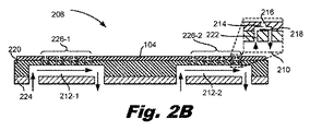
図2Bおよび図2Cは、流体吐出ダイ(208)の断面図である。より特定的には、図2Bおよび図2Cは、図2AのA−Aつ断面図である。図2Bおよび図2Cは各々、特定の種類の内蔵された横断流路(212)を図解している。図2Bおよび図2Cにおいては、参照番号212は流体の流れではなく内蔵された横断流路を参照しており、その流体の流れは矢印によって示されていることに留意されたい。
2B and 2C are cross-sectional views of the fluid discharge die (208). More specifically, FIGS. 2B and 2C are cross-sectional views taken along the line AA of FIG. 2A. 2B and 2C each illustrate a particular type of built-in cross-passage (212). Note that in FIGS. 2B and 2C,
何よりも、図2Bおよび図2Cは、ノズル(210)のアレイを示している。簡単化のために、図2Bおよび図2Cにおいては、1つのノズル(210)が参照番号で示されている。流体を吐出するために、ノズル(210)は多数の部品を含んでいる。例えば、ノズル(210)は、吐出すべき量の流体を保持する吐出チャンバ(214)、その量の流体がそれを通って吐出される開口(216)、および吐出チャンバ(214)内部に配置され、その量の流体を開口(216)を通して吐出させるための吐出流体アクチュエータ(218)を含んでいる。吐出チャンバ(214)およびノズル開口(216)は、流路基板(220)の上部に配置されたノズル基板(104)に画定されていてよい。幾つかの例においては、ノズル基板(104)はSU−8または他の材料で形成される。 Above all, FIGS. 2B and 2C show an array of nozzles (210). For simplicity, in FIGS. 2B and 2C, one nozzle (210) is indicated by a reference number. To discharge the fluid, the nozzle (210) contains a large number of parts. For example, the nozzle (210) is located inside a discharge chamber (214) that holds an amount of fluid to be discharged, an opening (216) through which that amount of fluid is discharged, and a discharge chamber (214). Includes a discharge fluid actuator (218) for discharging that amount of fluid through the opening (216). The discharge chamber (214) and nozzle opening (216) may be defined by a nozzle substrate (104) located above the flow path substrate (220). In some examples, the nozzle substrate (104) is made of SU-8 or other material.
吐出アクチュエータ(218)について見ると、吐出流体アクチュエータ(218)は、噴射抵抗器または他のサーマルデバイス、圧電素子、または吐出チャンバ(214)から流体を吐出するための他の機構を含んでいてよい。例えば、吐出器(218)は噴射抵抗器であってよい。噴射抵抗器は印加された電圧に応じて加熱される。噴射抵抗器が加熱されると、吐出チャンバ(214)内にある流体の一部が気化して気泡を形成する。この気泡は流体を開口(216)から、印刷媒体上へと押し出す。気化された流体の気泡が破裂すると、流体は通路(222)から吐出チャンバ(214)へと引き込まれ、この過程が繰り返される。この例においては、流体吐出ダイ(208)はサーマルインクジェット(TIJ)流体吐出ダイ(208)であってよい。 Looking at the discharge actuator (218), the discharge fluid actuator (218) may include an injection resistor or other thermal device, a piezoelectric element, or another mechanism for discharging fluid from the discharge chamber (214). .. For example, the ejector (218) may be an injection resistor. The injection resistor is heated according to the applied voltage. When the injection resistor is heated, a part of the fluid in the discharge chamber (214) vaporizes to form bubbles. The bubbles push the fluid through the opening (216) onto the print medium. When the vaporized fluid bubbles burst, the fluid is drawn from the passage (222) into the discharge chamber (214) and this process is repeated. In this example, the fluid discharge die (208) may be a thermal inkjet (TIJ) fluid discharge die (208).
別の例においては、吐出流体アクチュエータ(218)は圧電素子であってよい。電圧が印加されるにつれて、圧電素子は形状を変化させ、これが吐出チャンバ(214)内に圧力パルスを生成して、流体を開口(216)から、印刷媒体上へと押し出す。この例においては、流体吐出ダイ(208)はピエゾ電気型インクジェット(PIJ)流体吐出ダイ(208)であってよい。 In another example, the discharge fluid actuator (218) may be a piezoelectric element. As the voltage is applied, the piezoelectric element changes shape, which creates a pressure pulse in the discharge chamber (214), pushing the fluid out of the opening (216) onto the print medium. In this example, the fluid discharge die (208) may be a piezoelectric inkjet (PIJ) fluid discharge die (208).
流体吐出ダイ(208)はまた、流路基板(220)に形成された通路(222)のアレイを含んでいる。流路(222)は流体を対応する吐出チャンバ(214)へ、また吐出チャンバ(214)から配送する。幾つかの例においては、通路(222)流路基板(220)の穿孔された膜に形成される。例えば、流路基板(220)はシリコンから形成されていてよく、そして通路(222)は、流路基板(220)の一部を形成する、穿孔されたシリコン膜に形成されていてよい。すなわち、この膜には孔が穿孔されていてよく、この孔はノズル基板(104)と接合された場合に吐出チャンバ(214)と整列して、吐出過程において流体が流入および流出する経路を形成する。図2Bおよび図2Cに示されているように、各々の吐出チャンバ(214)には2つの通路(222)が対応していてよく、この対のうち1つの通路(222)は吐出チャンバ(214)への入口となり、他方の通路(222)は吐出チャンバ(214)からの出口となる。幾つかの例においては、通路(222)は円形の孔、角が丸められた正方形の孔、または他の種類の通路であってよい。 The fluid discharge die (208) also includes an array of passages (222) formed in the flow path substrate (220). The flow path (222) delivers the fluid to and from the corresponding discharge chamber (214). In some examples, it is formed on the perforated membrane of the passage (222) channel substrate (220). For example, the flow path substrate (220) may be formed of silicon, and the passage (222) may be formed of a perforated silicon film that forms part of the flow path substrate (220). That is, the membrane may be perforated with holes that align with the discharge chamber (214) when joined to the nozzle substrate (104) to form paths for fluid inflow and outflow during the discharge process. do. As shown in FIGS. 2B and 2C, each discharge chamber (214) may be associated with two passages (222), one of the pair of passages (222) being the discharge chamber (214). ), And the other passage (222) is an exit from the discharge chamber (214). In some examples, the passage (222) may be a circular hole, a square hole with rounded corners, or another type of passage.
流体吐出ダイ(208)はまた、内蔵された横断流路(212)のアレイを含んでいる。 The fluid discharge die (208) also includes an array of built-in transverse channels (212).
内蔵された横断流路(212)は流路基板(220)の背面側に形成されており、流体を通路(222)へ、また通路(222)から配送する。1つの例では、内蔵された横断流路(212)の各々は、通路(222)のアレイの複数の通路(222)のそれぞれと流体的に接続されている。幾つかの例においては、内蔵された横断流路(212)を通る流体の経路は、矢印によって示されているように、通路(222)を通る流れに対して垂直である。すなわち、流体は流入口から入り、内蔵された横断流路(104)を通過し、それぞれの通路(222)へと通過し、そして流出口から出て、関連する流体配送システムにある他の流体と混合される。流入口、内蔵された横断流路(212)および流出口を通る流れは、図2Bおよび図2Cにおいて矢印によって示されている。 The built-in cross-passage (212) is formed on the back surface side of the flow path substrate (220), and delivers the fluid to the passage (222) and from the passage (222). In one example, each of the built-in cross passages (212) is fluidly connected to each of the plurality of passages (222) in the array of passages (222). In some examples, the fluid path through the built-in transverse passage (212) is perpendicular to the flow through the passage (222), as indicated by the arrow. That is, the fluid enters through the inlet, passes through the built-in cross-passage (104), passes through each passage (222), and exits the outlet, the other fluid in the associated fluid delivery system. Is mixed with. The flow through the inlet, the built-in cross-passage (212) and the outlet is indicated by arrows in FIGS. 2B and 2C.
内蔵された横断流路(212)は、任意の数の表面によって画定されていてよい。例えば、内蔵された横断流路(212)の1つの表面は、通路(222)が形成されている流路基板(220)の膜部分によって画定される。別の表面は蓋基板(224)によって画定され、そして他の表面は、図2Dに示されているようにリブによって画定されている。 The built-in transverse channel (212) may be defined by any number of surfaces. For example, one surface of the built-in transverse passage (212) is defined by a membrane portion of the passage substrate (220) in which the passage (222) is formed. Another surface is defined by the lid substrate (224) and the other surface is defined by ribs as shown in FIG. 2D.
アレイの個々の横断流路(212)は、通路(222)および特定の行にある対応する吐出チャンバ(214)に対応していてよい。例えば、図2Aに示されているように、ノズル(210)のアレイは複数の行に配列されていてよく、そして各々の横断流路(212)は1つの行と整列していてよく、かくしてある行にあるノズル(210)は同じ横断流路(212)を共有するようになる。図2Aは複数行のノズル(210)を直線状に示しているが、複数行のノズル(210)は傾斜状、湾曲状、山形状、またはその他の配向であってよい。従って、これらの例においては、内蔵された横断流路(212)も同様に、傾斜状、湾曲状、山形状、またはその他の配向であってよく、ノズル(210)の配置に対して整列される。別の例においては、特定の行の通路(222)は複数の横断流路(212)に対応していてよい。すなわち複数の行は直線状であってよいが、しかし内蔵された横断流路(212)は傾斜されていてよい。ノズル(210)の行ごとについて、内蔵された横断流路(212)を特定的に参照したが、幾つかの例においては、複数行のノズル(210)が単一の内蔵された横断流路(212)に対応していてよい。 The individual transverse passages (212) of the array may correspond to the passage (222) and the corresponding discharge chamber (214) in a particular row. For example, as shown in FIG. 2A, the array of nozzles (210) may be arranged in multiple rows, and each cross-channel (212) may be aligned with one row, thus. Nozzles (210) in a row will share the same cross-passage (212). FIG. 2A shows a plurality of rows of nozzles (210) in a straight line, but the plurality of rows of nozzles (210) may be inclined, curved, mountain-shaped, or other oriented. Thus, in these examples, the built-in transverse channel (212) may also be inclined, curved, mountain-shaped, or other oriented and aligned with respect to the arrangement of the nozzles (210). NS. In another example, the passage (222) in a particular row may correspond to a plurality of cross passages (212). That is, the plurality of rows may be linear, but the built-in cross-passage (212) may be inclined. For each row of nozzles (210), the built-in cross-passage (212) was specifically referred to, but in some examples a single built-in cross-passage with multiple rows of nozzles (210). It may correspond to (212).
幾つかの例においては、内蔵された横断流路(212)は流体を、通路(222)のアレイの別の異なる部分集合に属する行へと配送する。例えば、図2Cに示されているように、単一の内蔵された横断流路(212)が流体を、第1の部分集合(226−1)に属するノズル(210)の行および第2の部分集合(226−2)に属するノズル(210)の行に配送してよい。この例においては、1つの種類の流体、例えば1つのインク色を、異なる部分集合(226)へと供給することができる。具体的な例においては、モノクロ流体吐出ダイ(208)は、ノズル(210)の複数の部分集合(226)にわたる、1つの内蔵された横断流路(212)を実施してよい。 In some examples, the built-in transverse channel (212) delivers the fluid to a row that belongs to another different subset of the array of passages (222). For example, as shown in FIG. 2C, a single built-in cross-passage (212) brings fluid to a row of nozzles (210) belonging to the first subset (226-1) and a second. It may be delivered to the row of nozzles (210) belonging to the subset (226-2). In this example, one type of fluid, eg, one ink color, can be supplied to different subsets (226). In a specific example, the monochrome fluid discharge die (208) may carry out one built-in cross-passage (212) over a plurality of subsets (226) of the nozzle (210).
幾つかの例においては、内蔵された横断流路(212)は流体を、通路(222)のアレイの単一の部分集合(226)に属する行へと配送する。例えば、図2Bに示されているように、第1の横断流路(212−1)は流体を第1の部分集合(226−1)に属するノズル(210)の行へと配送し、そして第2の横断流路(212−2)は流体を第2の部分集合(226−2)に属するノズル(210)の行へと配送する。この例においては、異なる種類の流体、例えば異なるインク色を、異なる部分集合(226)へと供給することができる。こうした流体吐出ダイ(208)は、多色印刷流体カートリッジにおいて使用してよい。 In some examples, the built-in transverse channel (212) delivers the fluid to a row belonging to a single subset (226) of the array of passages (222). For example, as shown in FIG. 2B, the first transverse flow path (212-1) delivers the fluid to the row of nozzles (210) belonging to the first subset (226-1), and The second transverse channel (212-2) delivers the fluid to the row of nozzles (210) belonging to the second subset (226-2). In this example, different types of fluids, such as different ink colors, can be supplied to different subsets (226). Such a fluid discharge die (208) may be used in a multicolor printing fluid cartridge.
これらの内蔵された横断流路(212)は、流体吐出ダイ(208)を通る改善された流体流れを促進する。例えば、内蔵された横断流路(212)がなければ、流体吐出ダイ(208)の背面側を通る流体は通路(222)に十分近接して通過せず、ノズル(210)を透過する流体と十分に混合しない場合がある。しかしながら、内蔵された横断流路(212)は流体をノズル(210)の近傍へと引き入れ、かくしてより向上された流体混合を促進する。この増大された流体流れはまた、使用済の流体がノズル(210)から取り出されることによってノズルの健全性を改善させるが、この使用済の流体は、ノズル(210)全体にわたって再使用された場合には、ノズル(210)に損傷を与える可能性がある。 These built-in transverse channels (212) facilitate improved fluid flow through the fluid discharge die (208). For example, without the built-in cross-passage (212), the fluid passing through the back side of the fluid discharge die (208) would not pass close enough to the passage (222) and would pass through the nozzle (210). It may not mix well. However, the built-in transverse channel (212) draws fluid closer to the nozzle (210), thus facilitating improved fluid mixing. This increased fluid flow also improves nozzle integrity by removing used fluid from the nozzle (210), but if this used fluid is reused throughout the nozzle (210). May damage the nozzle (210).
図2Dは、流体吐出ダイ(208)の断面図である。より特定的には、図2Dは図2AにおけるB−B線に沿って取った断面図である。図2Dは、流体吐出ダイ(208)の長さに沿った、多数の内蔵された横断流路(212)を示している。図2Dは特定の数の内蔵された横断流路(212)を示しているが、流体吐出ダイ(208)はこれらの内蔵された横断流路(212)を任意の数で含んでいてよい。 FIG. 2D is a cross-sectional view of the fluid discharge die (208). More specifically, FIG. 2D is a cross-sectional view taken along line BB in FIG. 2A. FIG. 2D shows a number of built-in transverse channels (212s) along the length of the fluid discharge die (208). Although FIG. 2D shows a specific number of built-in cross-passage channels (212), the fluid discharge die (208) may include any number of these built-in cross-passage channels (212).
図2Dはまた通路(222)を示しており、流体はこれを通って吐出チャンバ(214)へと渡される。簡単化のために、単一の通路(222)および内蔵された横断流路(212)が参照番号と共に示されている。図2Dは、流路基板(220)から形成されている内蔵された横断流路(212)を部分的に確定するリブを図解しているが、幾つかの例においては、内蔵された横断流路は蓋基板(224)から形成されていてよく、この蓋基板(224)はガラス、シリコン、または他の材料から形成されていてよい。 FIG. 2D also shows a passage (222) through which fluid is passed to the discharge chamber (214). For simplicity, a single passage (222) and a built-in cross passage (212) are shown with a reference number. FIG. 2D illustrates a rib that partially determines the built-in cross-passage (212) formed from the flow path substrate (220), but in some examples, the built-in cross-flow. The path may be formed from a lid substrate (224), which lid substrate (224) may be formed from glass, silicon, or other material.
図3は、本願に記載された原理の例に従う、内蔵された横断流路(212)を備えた流体吐出ダイ(図2A、208)の断面図である。具体的には図3は、単一の通路(222)の下側を通る、内蔵された横断流路(212)の一部分を示している。図3に示されている要素は縮尺通りではなく、図解の目的で拡大されていることに注意されたい。図3は、内蔵された横断流路(212)および通路(222)を通る流体の流れを明確に示している。示されているように、流体の流れは垂直になっている。すなわち、流体は内蔵された横断流路(212)を通って流れるにつれ、通路(222)を通過するに際して垂直に方向を変化させ、ノズル(図2A、210)へと差し向けられる。 FIG. 3 is a cross-sectional view of a fluid discharge die (FIGS. 2A, 208) with a built-in transverse channel (212), according to an example of the principles described herein. Specifically, FIG. 3 shows a portion of a built-in cross-passage (212) that passes underneath a single passage (222). Note that the elements shown in FIG. 3 are not scaled and are magnified for illustration purposes. FIG. 3 clearly shows the flow of fluid through the built-in transverse passage (212) and passage (222). As shown, the fluid flow is vertical. That is, as the fluid flows through the built-in cross-passage (212), it changes direction vertically as it passes through the passage (222) and is directed to the nozzles (FIGS. 2A, 210).
幾つかの例においては、吐出用の流体アクチュエータ(図2B、218)、吐出チャンバ(214−1、214−2)、および開口(216−1、216−2)に加えて、各々のノズル(図2A、210)は、流体を対応する吐出チャンバ(214)へ、また対応する吐出チャンバ(214)から配送するための流路(328−1、328−2)を含んでいてよい。こうした流路(328)は、小体積の流体(例えば、ピコリットル規模、ナノリットル規模、マイクロリットル規模、ミリリットル規模、等々)の搬送を促進するために、十分に小さな大きさ(例えば、ナノメートルサイズの規模、マイクロメートルサイズの規模、ミリメートルサイズの規模、等々)であってよい。この例においては、ノズル(図2A、210)に対応する流路(328−1、328−2)および通路(222)は、微小再循環ループを形成する。幾つかの例においては、ポンプ式流体アクチュエータが流路(328)内部に配置されて、流体を吐出チャンバ(214)へ、また吐出チャンバ(214)から移動させる。こうした微小流路(328−1、328−2)は、そこを通って流れる流体の沈積を防止し、開口(216)を通る吐出のために新鮮な流体が入手可能であることを保証する。流体アクチュエータは、吐出器(図2B、218)およびポンプアクチュエータの両者とも、静電膜アクチュエータ、機械的/インパクト駆動膜アクチュエータ、磁歪式駆動アクチュエータ、または電気的な付勢に応じて流体の移動を生じさせうる、他のこうした要素であってよい。 In some examples, in addition to the fluid actuators for discharge (FIGS. 2B, 218), discharge chambers (214-1, 214-2), and openings (216-1, 216-2), each nozzle ( 2A, 210) may include flow paths (328-1, 328-2) for delivering fluid to and from the corresponding discharge chamber (214). These channels (328) are small enough (eg, nanometers) to facilitate the transport of small volumes of fluid (eg, picolitre scale, nanoliter scale, microliter scale, milliliter scale, etc.). It may be size scale, micrometer size scale, milliliter size scale, etc.). In this example, the flow paths (328-1, 328-2) and passages (222) corresponding to the nozzles (FIGS. 2A, 210) form a microrecirculation loop. In some examples, a pump fluid actuator is placed inside the flow path (328) to move the fluid to and from the discharge chamber (214). Such microchannels (328-1, 328-2) prevent the sedimentation of fluid flowing through it and ensure that fresh fluid is available for discharge through the opening (216). The fluid actuator, both the ejector (FIG. 2B, 218) and the pump actuator, moves the fluid in response to an electrostatic membrane actuator, a mechanical / impact drive membrane actuator, a magnetostrictive drive actuator, or an electrical bias. It may be other such factor that can occur.
上記したように、こうした微小再循環ループは新鮮な流体を吐出チャンバ(214)へと提供し、かくしてノズル(図2A、210)の有効寿命を増大させる。これは、ノズル(図2A、210)は新鮮な流体を供給された場合に最適に動作するためである。 As mentioned above, these microrecirculation loops provide fresh fluid to the discharge chamber (214) and thus increase the useful life of the nozzles (FIGS. 2A, 210). This is because the nozzles (FIGS. 2A, 210) operate optimally when supplied with fresh fluid.
図4Aおよび図4Bは、本願に記載された原理の例に従う、内蔵された横断流路(図2B、212)を備えた流体吐出ダイ(図2A、208)を有する流体吐出デバイス(100)の断面図である。具体的には、図4Aは直線的な流体供給スロットを備えた流体吐出デバイス(100)を示しており、そして図4Bは先細りになっている流体供給スロットを備えた流体吐出デバイス(100)を示している。上記したように、成形可能な材料(102)は流体供給スロットが出口に向けて先細りになることを許容し、これはスライバーダイのような、幅のより狭い流体吐出ダイ(208)を対応する印刷デバイスにおいて実装することを可能にする。 4A and 4B show a fluid discharge device (100) having a fluid discharge die (FIGS. 2A, 208) with a built-in cross-sectional flow path (FIGS. 2B, 212) according to an example of the principles described herein. It is a sectional view. Specifically, FIG. 4A shows a fluid discharge device (100) with a linear fluid supply slot, and FIG. 4B shows a fluid discharge device (100) with a tapered fluid supply slot. Shows. As mentioned above, the moldable material (102) allows the fluid supply slot to taper towards the outlet, which corresponds to a narrower fluid discharge die (208), such as a sliver die. Allows implementation in printing devices.
図4Aおよび図4Bは、異なる別々の内蔵された横断流路(212−1、212−2)が、相互に異なっていてよい流体を、ノズル(図2A、210)の異なる別々の部分集合(226−1、226−2)へと供給している場合について示している。図4Aおよび図4Bはまた、成形可能な材料(102)中への、流体吐出ダイ(図2A、208)の埋め込みについて示している。図4Aおよび図4Bはまた、成形可能な材料(102)中の供給スロットを示しており、流体はこれを通って通路(図2B、222)に流体的に接続された流入口および流出口へと流れ、図4Bにおいてこの供給スロットはファンアウトされている。幾つかの場合には、成形可能な材料(102)の供給スロットは、蓋基板(224)の下側に配置された、成形可能な材料(102)のインサートによって画定されていてよい。これらの供給スロットは、流体を複数の内蔵された横断流路(図2B、212)へと供給するように、長く延ばされていてよい。図4Aおよび図4Bはまた、成形可能な材料(102)、流体吐出ダイ(図2A、208)、および流体吐出デバイス(100)の全体を支持するキャリア基板(106)を示している。 In FIGS. 4A and 4B, different separate built-in cross-flow channels (212-1, 212-2) allow different fluids to be different from each other, with different separate subsets of nozzles (FIGS. 2A, 210). The case of supplying to 226-1 and 226-2) is shown. 4A and 4B also show the embedding of a fluid discharge die (FIGS. 2A, 208) in a moldable material (102). 4A and 4B also show supply slots in the moldable material (102) through which fluid flows to inlets and outlets fluidly connected to passages (FIGS. 2B and 222). In FIG. 4B, this supply slot is fan-out. In some cases, the feed slot for the moldable material (102) may be defined by an insert of the moldable material (102) located underneath the lid substrate (224). These supply slots may be extended long enough to supply the fluid to a plurality of built-in transverse channels (FIG. 2B, 212). 4A and 4B also show a moldable material (102), a fluid discharge die (FIGS. 2A, 208), and a carrier substrate (106) that supports the entire fluid discharge device (100).
図4Aおよび図4Bはまた、キャリア基板(106)のファンアウトを示している。すなわち、キャリア基板(106)の外側リブは、ダイ(220)の幅を越えたところに位置している。すなわち、成形可能な材料(106)は、流体吐出ダイそれ自体を物理的に拡幅することなしに、流体吐出ダイに対する流体的インタフェースを事実上拡幅している。このことは、より小さな、そしてより費用対効果の良い流体吐出ダイを使用することを可能にする。 4A and 4B also show the fanout of the carrier substrate (106). That is, the outer rib of the carrier substrate (106) is located beyond the width of the die (220). That is, the moldable material (106) effectively widens the fluid interface to the fluid discharge die without physically widening the fluid discharge die itself. This makes it possible to use smaller and more cost effective fluid discharge dies.
図5は、本願に記載された原理の例に従う、内蔵された横断流路(212−1、212−2)を備えた流体吐出ダイ(208)の下側の等測図である。簡単化のために、内蔵された横断流路(212−1、212−2)および関連するリブ(530−1、530−2)の僅かなものだけが参照番号で指示されている。 FIG. 5 is a lower isometric view of a fluid discharge die (208) with a built-in transverse flow path (212-1, 212-2) according to an example of the principles described herein. For simplicity, only a few of the built-in transverse channels (212-1, 212-2) and related ribs (530-1, 530-2) are indicated by reference numbers.
図5は、流体吐出ダイ(208)を通る、特に内蔵された横断流路(212)を通る流体の流れ経路を明示している。図5に示された例においては、ノズル(図2A、210)のアレイは2つの部分集合(図2B、226−1、226−2)に分割されていてよいが、しかしノズル(図2A、210)のアレイは任意の数の部分集合(図2B、226)へと分割されることができる。 FIG. 5 illustrates a fluid flow path through a fluid discharge die (208), especially through a built-in cross-passage (212). In the example shown in FIG. 5, the array of nozzles (FIGS. 2A, 210) may be divided into two subsets (FIGS. 2B, 226-1, 226-2), but the nozzles (FIG. 2A, The array of 210) can be divided into any number of subsets (FIG. 2B, 226).
この例においては、流体は流入口へと通過され、この流入口は多数の内蔵された横断流路(212)によって共有されていてよい。流体は次いで内蔵された横断流路(212)へと通され、この内蔵された横断流路(212)は部分的にはリブ(530−1、530−1)および蓋基板(224)によって画定されている。流体が内蔵された横断流路(212)を通って流れると、それは通路(図2B、222)およびノズル(図2A、210)を通って差し向けられ、このノズル(図2A、210)は微小再循環ループを含んでいてよい。過剰の流体は次いで、内蔵された横断流路(212)へと搬送し戻され、そこで内蔵された横断流路(212)の流出口から放出される。 In this example, the fluid is passed to the inlet, which may be shared by a number of built-in cross-passage channels (212). The fluid is then passed through a built-in cross-passage (212), which is partially defined by ribs (530-1, 530-1) and a lid substrate (224). Has been done. As the fluid flows through the built-in transverse passage (212), it is directed through the passage (FIG. 2B, 222) and the nozzle (FIG. 2A, 210), which nozzle (FIG. 2A, 210) is microscopic. It may include a recirculation loop. The excess fluid is then transported back to the built-in cross-passage (212) where it is discharged from the outlet of the built-in cross-passage (212).
図6は、本願に記載された原理の例に従う、内蔵された横断流路(図2B、212)を有する流体吐出デバイス(100)を含んでいる印刷流体カートリッジ(632)のブロック図である。印刷流体カートリッジ(632)は、流体を吐出するために印刷システム内部において使用される。幾つかの例においては、印刷流体カートリッジ(632)は、例えば交換式カートリッジ(632)として、システムから取り外されてよい。幾つかの例においては、印刷流体カートリッジ(632)は基材幅の印刷バーであり、そして流体吐出デバイス(100)のアレイは複数のプリントヘッドへとグループ化されて、それらは流体が付着される基材の幅にわたって互い違いに配置されている。こうしたプリントヘッドの例が図8に示されている。 FIG. 6 is a block diagram of a printing fluid cartridge (632) containing a fluid discharge device (100) with a built-in transverse channel (FIGS. 2B, 212), according to an example of the principles described herein. The printing fluid cartridge (632) is used inside the printing system to eject the fluid. In some examples, the printing fluid cartridge (632) may be removed from the system, for example as a replaceable cartridge (632). In some examples, the print fluid cartridge (632) is a substrate width print bar, and the array of fluid discharge devices (100) is grouped into multiple printheads, which are fluid-attached. They are staggered across the width of the substrate. An example of such a printhead is shown in FIG.
印刷流体カートリッジ(632)は、印刷流体カートリッジ(632)の部品を収容するハウジング(634)を含んでいる。このハウジング(634)は、所定量の流体を流体吐出デバイス(100)に供給するための、流体リザーバ(636)を収容している。一般に、流体はリザーバ(636)および流体吐出デバイス(100)の間を流れる。幾つかの例においては、流体吐出デバイス(100)に供給される流体の一部は動作中に消費され、そして印刷中に消費されなかった流体は、流体リザーバ(636)に戻される。幾つかの例においては、流体はインクであってよい。1つの具体的な例においては、インクは種々の流体の中でも、水系の紫外線(UV)インク、薬液、または3D印刷材料であってよい。 The printing fluid cartridge (632) includes a housing (634) that houses the parts of the printing fluid cartridge (632). The housing (634) houses a fluid reservoir (636) for supplying a predetermined amount of fluid to the fluid discharge device (100). Generally, the fluid flows between the reservoir (636) and the fluid discharge device (100). In some examples, some of the fluid supplied to the fluid discharge device (100) is consumed during operation and the fluid not consumed during printing is returned to the fluid reservoir (636). In some examples, the fluid may be ink. In one specific example, the ink may be a water-based ultraviolet (UV) ink, a chemical solution, or a 3D printing material, among various fluids.
図7は、本願に記載された原理の例に従う、基材幅の印刷バー(740)内に内蔵された横断流路(図2B、212)を備えた多数の流体吐出デバイス(100−1、100−2、100−3、100−4)を含んでいる印刷デバイス(738)のブロック図である。印刷デバイス(738)は、印刷基材(742)の幅にわたる印刷バー(740)、印刷バー(740)に関連する多数の流れレギュレータ(744)、基材搬送機構(746)、流体リザーバ(図6、636)のような印刷流体供給部(748)、およびコントローラ(750)を含んでいてよい。コントローラ(750)は、プログラミング、プロセッサ(単数または複数)、および関連するメモリ、並びに印刷デバイス(738)の作動要素を制御する他の電子回路および部品を表している。印刷バー(740)は、カットシートまたは連続紙、或いは他の印刷基材(742)の上に流体を分配するための、流体吐出デバイス(100)の配列を含んでいてよい。各々の流体吐出デバイス(100)は、流体供給部(748)から流れレギュレータ(744)内を通って延びる流体経路を通り、そして印刷バー(740)に規定された多数のトランスファー成形された流体流路(752)を通して、流体を受け取る。 FIG. 7 shows a number of fluid discharge devices (100-1, 212) with a transverse flow path (FIGS. 2B, 212) built into a substrate width print bar (740), according to an example of the principles described herein. It is a block diagram of the printing device (738) including 100-2, 100-3, 100-4). The printing device (738) includes a printing bar (740) across the width of the printing substrate (742), a number of flow regulators (744) associated with the printing bar (740), a substrate transfer mechanism (746), and a fluid reservoir (FIG. A printing fluid supply unit (748) such as 6, 636) and a controller (750) may be included. The controller (750) represents programming, a processor (s), and associated memory, as well as other electronic circuits and components that control the working elements of the printing device (738). The print bar (740) may include an array of fluid ejection devices (100) for distributing the fluid onto a cut sheet or continuous paper, or other printing substrate (742). Each fluid discharge device (100) follows a fluid path extending from the fluid supply unit (748) through the flow regulator (744) and a number of transfer-formed fluid flows specified in the print bar (740). Receive the fluid through the path (752).
図8は、本願に記載された原理の例に従う、内蔵された横断流路(図2A、212)を備えた多数の流体吐出ダイ(208)を含んでいる流体吐出デバイス(841)のブロック図である。幾つかの例においては、流体吐出ダイ(208)は、成形可能な材料(102)で形成された細長い、一体型の成形パネル(843)に埋設され、多数の行(854)でもって端から端まで配置されている。流体吐出ダイ(208)は互い違い構成で配置されており、そこでは各々の行(854)にある流体吐出ダイ(208)は、その同じ行(854)にある別の流体吐出ダイ(208)と重なり合う。この配置において、流体吐出ダイ(208)の各々の行(854)は、図8において点線で図示されているように、トランスファー成形された別の流体流路(856)から流体を受け取る。成形パネル(843)の内部には、流体を流体吐出ダイ(208)へ、また流体吐出ダイ(208)から配送する、流体供給スロットがある。図8は、例えばシアン、マゼンタ、イエロー、およびブラックといった4つの異なる色で印刷する場合に、互い違いの流体吐出ダイ(208)の4つの行(854)に供給を行う4つの流体流路(856)を示しているが、他の適切な構成もまた可能である。 FIG. 8 is a block diagram of a fluid discharge device (841) comprising a large number of fluid discharge dies (208) with a built-in transverse channel (FIGS. 2A, 212) according to an example of the principles described herein. Is. In some examples, the fluid discharge die (208) is embedded in an elongated, one-piece molded panel (843) made of a moldable material (102) and from the end with a large number of rows (854). It is arranged to the end. The fluid discharge dies (208) are arranged in a staggered configuration, where the fluid discharge dies (208) in each row (854) are with another fluid discharge dies (208) in the same row (854). overlap. In this arrangement, each row (854) of the fluid discharge die (208) receives fluid from another transfer-molded fluid flow path (856), as illustrated by the dotted line in FIG. Inside the molding panel (843), there is a fluid supply slot that delivers the fluid to and from the fluid discharge die (208). FIG. 8 shows four fluid channels (856) supplying four rows (854) of staggered fluid discharge dies (208) when printing in four different colors, for example cyan, magenta, yellow, and black. ), But other suitable configurations are also possible.
図9は、本願に記載された原理の例に従う、内蔵された横断流路(図2A、212)を備えた流体吐出デバイス(図1、100)を形成するための方法(900)の流れ図である。この方法(900)によれば、ノズル(図2A、210)のアレイおよび通路(図2B、222)が形成される(ブロック901)。幾つかの例においては、通路(図2B、222)は穿孔されたシリコン膜の一部であってよい。このノズル(図2A、210)、または正確にはノズル(図2A、210)の開口(図2B、216)および吐出チャンバ(図2B、214)は、SU−8のようなノズル基板(図1、104)から形成されていてよい。従って、ノズル(図2A、210)のアレイおよび通路(図2B、222)を形成すること(ブロック901)は、穿孔されたシリコン膜をSU−8ノズル基板(図1、104)と接合することを含んでいてよい。 FIG. 9 is a flow diagram of a method (900) for forming a fluid discharge device (FIGS. 1, 100) with a built-in transverse channel (FIGS. 2A, 212) according to an example of the principles described herein. be. According to this method (900), an array of nozzles (FIGS. 2A, 210) and passages (FIG. 2B, 222) are formed (block 901). In some examples, the passage (FIG. 2B, 222) may be part of a perforated silicon film. The nozzle (FIG. 2A, 210), or more precisely the nozzle (FIG. 2A, 210) opening (FIG. 2B, 216) and ejection chamber (FIG. 2B, 214), is a nozzle substrate (FIG. 1) such as SU-8. , 104). Therefore, forming an array of nozzles (FIGS. 2A, 210) and passageways (FIGS. 2B, 222) (block 901) joins the perforated silicon film to a SU-8 nozzle substrate (FIG. 1, 104). May include.
次いで、内蔵された横断流路(図2B、212)が形成される(ブロック902)。内蔵された横断流路(図2B、212)を形成すること(ブロック902)は、通路(図2B、222)が形成されている膜の背面側にリブ(図5、530)を接着し、そして蓋基板(図2B、224)を取り付けることを含んでいてよい。別の例においては、形成すること(ブロック902)は、流路基板(図2B、220)をエッチングして、内蔵された横断流路(図2B、212)を部分的に確定するリブ(図5、530)を形成することを含んでいてよい。 Next, a built-in cross-passage (FIG. 2B, 212) is formed (block 902). Forming the built-in cross-passage (FIGS. 2B, 212) (block 902) involves adhering ribs (FIG. 5, 530) to the back side of the membrane on which the passage (FIG. 2B, 222) is formed. And it may include attaching a lid substrate (FIG. 2B, 224). In another example, forming (block 902) is a rib (FIG. 2B, 220) that etches the flow path substrate (FIG. 2B, 220) to partially determine the built-in transverse channel (FIG. 2B, 212). It may include forming 5, 530).
内蔵された横断流路(図2B、212)が形成され、そしてノズル(図2A、210)および通路(図2B、222)が形成されたなら、2つの部品は接合され(ブロック903)、内蔵された横断流路(図2B、212)を備えた流体吐出ダイ(図2A、208)が形成される。流体吐出ダイ(図2A、208)が形成されたなら、流体吐出ダイ(図2A、208)は成形可能な材料(図1、102)へと埋設(ブロック904)されるが、この成形可能な材料(図1、102)は、通路(図2B、222)および対応する内蔵された横断流路(図2A、212)と整列され、流体を供給するための供給スロットを含んでいる。図10Aから図10Dは、本願に記載された原理の例に従う、内蔵された横断流路(図2B、212)を備えた流体吐出デバイス(図1、100)を製造するための方法である。 If a built-in cross-flow channel (FIGS. 2B, 212) is formed, and a nozzle (FIG. 2A, 210) and a passage (FIG. 2B, 222) are formed, the two parts are joined (block 903) and built-in. A fluid discharge die (FIG. 2A, 208) with a cross-passage (FIG. 2B, 212) is formed. Once the fluid discharge die (FIGS. 2A, 208) has been formed, the fluid discharge die (FIG. 2A, 208) is embedded (block 904) in a moldable material (FIGS. 1, 102), which is moldable. The material (FIGS. 1, 102) is aligned with the passage (FIG. 2B, 222) and the corresponding built-in transverse passage (FIG. 2A, 212) and includes a feed slot for feeding the fluid. 10A-10D are methods for manufacturing a fluid discharge device (FIGS. 1, 100) with a built-in transverse channel (FIGS. 2B, 212), according to an example of the principles described herein.
流体吐出ダイ(208)が、図10Aに示されたようにして形成される。この流体吐出ダイ(208)は、あるゆる任意の方法で形成されてよい。一般には、ノズル開口(216)および吐出チャンバ(214)が、SU−8のような材料から形成されていてよいノズル基板(104)に形成される。ノズル基板(104)への開口(216)および吐出チャンバ(214)の形成は、エッチングまたはフォトリソグラフィを用いて行ってよい。形成された開口(216)および吐出チャンバ(214)を備えたこのノズル基板(104)は、次いで、形成された通路(222)を有すると共に、流体吐出ダイ(208)の流入口、流出口、およびリブ(530)を画定している層(1058)と接合される。 A fluid discharge die (208) is formed as shown in FIG. 10A. The fluid discharge die (208) may be formed by any method. Generally, a nozzle opening (216) and a discharge chamber (214) are formed on a nozzle substrate (104) which may be formed from a material such as SU-8. The formation of the opening (216) and ejection chamber (214) into the nozzle substrate (104) may be performed by etching or photolithography. The nozzle substrate (104) with the formed openings (216) and discharge chamber (214) then has the formed passages (222) as well as the inlets and outlets of the fluid discharge die (208). And joined with the layer (1058) defining the ribs (530).
図10Bに示されているように、流体吐出ダイ(208)は反転され、銅のような任意の材料から形成されていてよい担持ボード(1060)上に配置される。すなわち、ノズル基板(104)を表面を下向きにして担持ボード(1060)上にある。流体吐出ダイ(208)は、テープまたは他の接着性表面を介して、一時的に担持ボード(1060)に接着されてよい。 As shown in FIG. 10B, the fluid discharge die (208) is inverted and placed on a carrier board (1060) which may be made of any material such as copper. That is, the nozzle substrate (104) is placed on the supporting board (1060) with the surface facing down. The fluid discharge die (208) may be temporarily attached to the carrier board (1060) via tape or other adhesive surface.
次に、図10Cに示されているように、溶融状態の成形可能な材料(102)が流体吐出ダイ(208)の周囲に配置される。インサート(1062)が通路(222)のあたりに配置されてよく、かくして成形可能な材料(102)が内蔵された横断流路(図2B、212)、通路(図2B、222)、またはノズル(図2A、210)の部品の中へと流入して閉塞することがないようにされる。これらのインサート(1062)はまた、図10Dに示されているように、成形可能な材料(102)に供給スロットを画定する。 Next, as shown in FIG. 10C, a molten formable material (102) is placed around the fluid discharge die (208). An insert (1062) may be placed around the passage (222), thus a cross-passage (FIG. 2B, 212), passage (FIG. 2B, 222), or nozzle (FIG. 2B, 222) containing a moldable material (102). It is prevented from flowing into the parts of FIGS. 2A and 210) and being blocked. These inserts (1062) also define supply slots in the moldable material (102), as shown in FIG. 10D.
図10Dにおいては、構造体は正しい側が上を向くように反転され、担持ボード(1060)およびインサート(1062)は取り除かれ、そして構造体はキャリア基板(図1、106)に接着されて、内蔵された横断流路(212)を備えた流体吐出デバイス(100)が残されるようになる。 In FIG. 10D, the structure is flipped so that the correct side faces up, the carrier board (1060) and insert (1062) are removed, and the structure is glued to the carrier substrate (FIGS. 1, 106) and incorporated. A fluid discharge device (100) with the cross-sectional flow path (212) is left behind.
概略すると、こうした流体吐出ダイの使用は、1)流体中の水分濃度を維持することによってデキャップの蓋然性を低減し、2)ノズル内部でのより効率的な微小再循環を促進し、3)ノズルの健全性を改善し、4)ダイ近傍での流体の混合をもたらして印刷品質を向上させ、5)流体吐出ダイを対流によって冷却し、6)流体吐出ダイから気泡を除去し、そして7)ノズルの再プライミングを許容する。しかしながら、本願に開示されたデバイスは、多くの技術分野における他の事項および不具合に対処してよいと考えられる。 In summary, the use of such fluid discharge dies 1) reduces the probability of decap by maintaining the water concentration in the fluid, 2) promotes more efficient microrecirculation inside the nozzle, and 3) the nozzle. 4) Bring fluid mixing near the die to improve print quality, 5) Cool the fluid discharge die by convection, 6) Remove air bubbles from the fluid discharge die, and 7) Allow nozzle repriming. However, it is believed that the devices disclosed in this application may address other matters and defects in many technical areas.
以上の説明は、記載された原理の例を図解および記述するために提示されたものである。この説明は完全であることを意図したものではなく、またこれらの原理を開示された任意の形態だけに限定することを意図したものでもない。上記の教示に照らして、多くの修正および変形が可能である。 The above description is provided to illustrate and describe examples of the described principles. This description is not intended to be complete, nor is it intended to limit these principles to any disclosed form. Many modifications and modifications are possible in the light of the above teachings.
Claims (15)
各々のノズルが:
ノズル基板に形成された吐出チャンバ;
開口;および
吐出チャンバ内に配置された流体アクチュエータを含むノズルのアレイ;
ノズル基板の背面に接合された流路基板に形成され、流体を吐出チャンバへ、また吐出チャンバから配送するための通路のアレイ;および
流路基板の背面上に形成された、内蔵された横断流路のアレイであって、アレイの各々の内蔵された横断流路が通路のアレイの複数の通路のそれぞれと流体的に接続されている内蔵された横断流路のアレイを含む、流体吐出ダイと;
流体吐出ダイが配置されている成形可能な材料と、ここで成形可能な材料は流体を流体吐出ダイへ、また流体吐出ダイから配送する供給スロットを含んでおり;および
流体吐出ダイおよび成形可能な材料を支持するキャリア基板とを含む、流体吐出デバイス。 A fluid discharge die embedded in a moldable material:
Each nozzle is:
Discharge chamber formed on the nozzle substrate;
Aperture; and an array of nozzles containing fluid actuators located within the discharge chamber;
An array of passages formed on a flow path board joined to the back of the nozzle board to deliver fluid to and from the discharge chamber;
An array of built-in cross-passages formed on the back of the flow path board, with each built-in cross-passage of the array fluidly connected to each of the plurality of passages in the aisle array. With a fluid discharge die, including an array of built-in cross-passages.
The moldable material in which the fluid discharge die is located, and the moldable material here, includes a supply slot that delivers the fluid to and from the fluid discharge die; and the fluid discharge die and moldable. A fluid discharge device, including a carrier substrate that supports the material.
ノズルに対応する流路および通路は微小再循環ループを形成する、請求項1〜4の何れか一項に記載の流体吐出デバイス。 Each nozzle further comprises a flow path that directs the fluid to and from the corresponding discharge chamber; and the flow path and passage corresponding to the nozzle form a microrecirculation loop, claims 1-4. The fluid discharge device according to any one of the above.
成形パネルに埋設された複数の流体吐出ダイであって、各々の流体吐出ダイは:
各々のノズルが:
ノズル基板に形成された吐出チャンバ;
開口;および
吐出チャンバ内に配置された流体アクチュエータを含むノズルのアレイと;
ノズル基板の背面に接合された流路基板に形成され、流体を吐出チャンバへ、また吐出チャンバから配送するための通路のアレイと;および
流路基板の背面上に形成された、内蔵された横断流路のアレイであって、内蔵された横断流路のアレイの各々の内蔵された横断流路が通路のアレイの複数の通路のそれぞれと流体的に接続されている内蔵された横断流路のアレイとを含んでいる、流体吐出デバイスであって;
成形パネルは流体を流体吐出ダイへ、また流体吐出ダイから配送する供給スロットを含んでおり;および
流体吐出ダイおよび成形パネルを支持するキャリア基板とを含む、流体吐出デバイス。 Molded panels made from moldable materials;
Multiple fluid discharge dies embedded in the molding panel, each fluid discharge die is:
Each nozzle is:
Discharge chamber formed on the nozzle substrate;
Aperture; and an array of nozzles containing fluid actuators located within the discharge chamber;
Formed on a flow path board joined to the back of the nozzle board, with an array of passages for delivering fluid to and from the discharge chamber; and
An array of built-in cross-passages formed on the back of the flow path board, each of the built-in cross-passages of the built-in cross-passage array is a plurality of passages in the passage array. A fluid discharge device that includes a built-in cross-passage array that is fluidly connected to the device;
The molded panel includes a feed slot for delivering fluid to and from the fluid discharge die; and a fluid discharge device including a fluid discharge die and a carrier substrate supporting the molded panel.
流体を対応する吐出チャンバへ、また対応する吐出チャンバから差し向ける流路;
流体を流路を通して移動させるための2次的流体アクチュエータを含み;そして
ノズルに対応する流路および通路はノズルの微小再循環ループを形成する、請求項9の流体吐出デバイス。 Each nozzle is further:
A flow path that directs fluid to and from the corresponding discharge chamber;
The fluid discharge device of claim 9, wherein the flow path and passage corresponding to the nozzle form a microrecirculation loop of the nozzle, comprising a secondary fluid actuator for moving the fluid through the flow path.
流体吐出ダイは流体が付着される基材の幅にわたって互い違いに配置されている、請求項9または請求項10に記載の流体吐出デバイス。 The fluid discharge device of claim 9 or 10, wherein the printhead is a substrate width print bar; and fluid discharge dies are staggered across the width of the substrate to which the fluid adheres.
ノズルのアレイの異なる部分集合が異なる色に対応しており;
内蔵された横断流路の異なる部分集合が流体をノズルのアレイの異なる部分集合の行へと配送する、請求項9または請求項10に記載の流体吐出デバイス。 The printhead is a multicolor printhead;
Different subsets of the nozzle array correspond to different colors;
The fluid discharge device of claim 9 or 10, wherein different subsets of the built-in cross-passage deliver fluid to a row of different subsets of the array of nozzles.
ノズルのアレイをノズル基板に形成し、各々のノズルが、
吐出チャンバ;
開口;および
吐出チャンバ内に配置された流体アクチュエータを含んでおり;
通路のアレイを流路基板に形成し、ここで通路は流体を対応する吐出チャンバへ、また対応する吐出チャンバから配送し、
流路基板の背面上に多数の内蔵された横断流路を形成し、ここで多数の内蔵された横断流路は流体を通路へ、または通路から配送し;
アレイの各々の内蔵された横断流路が通路のアレイの複数の通路のそれぞれと流体的に接続されるように流路基板をノズル基板の背面に接合して流体吐出ダイを形成し;そして
流体吐出ダイを成形可能な材料に埋設し、ここで成形可能な材料は多数の内蔵された横断流路へと流体を供給する供給スロットを含む、方法。 A method for creating fluid discharge devices:
The Bruno nozzle of the array is formed in the nozzle substrate, each nozzle,
Discharge chamber;
Aperture; and
Includes fluid actuators located within the discharge chamber ;
An array of passages is formed on the flow path substrate, where the passages deliver fluid to and from the corresponding discharge chamber.
A large number of built-in cross-passages are formed on the back of the flow path board, where the large number of built-in cross-passages deliver fluid to or from the passage;
A flow board is joined to the back of the nozzle board to form a fluid discharge die so that each built-in cross- passage of the array is fluidly connected to each of the multiple passages of the array of passages; and the fluid. A method in which a discharge die is embedded in a moldable material, wherein the moldable material comprises a supply slot that feeds fluid to a number of built-in cross-passages.
Applications Claiming Priority (1)
| Application Number | Priority Date | Filing Date | Title |
|---|---|---|---|
| PCT/US2017/044742 WO2019027432A1 (en) | 2017-07-31 | 2017-07-31 | Fluidic ejection devices with enclosed cross-channels |
Publications (2)
| Publication Number | Publication Date |
|---|---|
| JP2020527492A JP2020527492A (en) | 2020-09-10 |
| JP6971377B2 true JP6971377B2 (en) | 2021-11-24 |
Family
ID=65234046
Family Applications (1)
| Application Number | Title | Priority Date | Filing Date |
|---|---|---|---|
| JP2020502713A Active JP6971377B2 (en) | 2017-07-31 | 2017-07-31 | Fluid discharge device with built-in cross-passage |
Country Status (5)
| Country | Link |
|---|---|
| US (1) | US11155086B2 (en) |
| EP (1) | EP3609712B1 (en) |
| JP (1) | JP6971377B2 (en) |
| CN (1) | CN110891792B (en) |
| WO (1) | WO2019027432A1 (en) |
Families Citing this family (6)
| Publication number | Priority date | Publication date | Assignee | Title |
|---|---|---|---|---|
| US11325125B2 (en) | 2017-04-23 | 2022-05-10 | Hewlett-Packard Development Company, L.P. | Particle separation |
| CN110891793B (en) * | 2017-07-31 | 2021-04-09 | 惠普发展公司,有限责任合伙企业 | Fluid ejection die with enclosed lateral channels |
| WO2020263234A1 (en) | 2019-06-25 | 2020-12-30 | Hewlett-Packard Development Company, L.P. | Molded structures with channels |
| WO2020263236A1 (en) * | 2019-06-25 | 2020-12-30 | Hewlett-Packard Development Company, L.P. | Molded structures with channels |
| EP4103406A4 (en) * | 2020-02-14 | 2023-11-01 | Hewlett-Packard Development Company, L.P. | Continuous fluid recirculation and recirculation on-demand prior to firing for thermal ejection of fluid having concentration of solids |
| CN118632781A (en) * | 2022-02-04 | 2024-09-10 | 惠普发展公司,有限责任合伙企业 | Fluid ejection device assembly |
Family Cites Families (43)
| Publication number | Priority date | Publication date | Assignee | Title |
|---|---|---|---|---|
| US7527357B2 (en) | 1997-07-15 | 2009-05-05 | Silverbrook Research Pty Ltd | Inkjet nozzle array with individual feed channel for each nozzle |
| US6309054B1 (en) | 1998-10-23 | 2001-10-30 | Hewlett-Packard Company | Pillars in a printhead |
| US6244694B1 (en) | 1999-08-03 | 2001-06-12 | Hewlett-Packard Company | Method and apparatus for dampening vibration in the ink in computer controlled printers |
| US6513896B1 (en) | 2000-03-10 | 2003-02-04 | Hewlett-Packard Company | Methods of fabricating fit firing chambers of different drop weights on a single printhead |
| JP4875997B2 (en) | 2007-02-16 | 2012-02-15 | 富士フイルム株式会社 | Liquid discharge head and liquid discharge apparatus |
| JP5593616B2 (en) | 2008-02-26 | 2014-09-24 | 株式会社リコー | Liquid ejection head and image forming apparatus |
| US8109607B2 (en) | 2008-03-10 | 2012-02-07 | Hewlett-Packard Development Company, L.P. | Fluid ejector structure and fabrication method |
| EP2296896B1 (en) | 2008-05-23 | 2022-05-18 | FUJIFILM Corporation | Fluid droplet ejecting |
| WO2010044775A1 (en) | 2008-10-14 | 2010-04-22 | Hewlett-Packard Development Company, L.P. | Fluid ejector structure |
| JP5375669B2 (en) | 2009-06-29 | 2013-12-25 | 株式会社リコー | Liquid ejection head, liquid droplet ejection apparatus, and image forming apparatus |
| US8240796B2 (en) * | 2009-07-09 | 2012-08-14 | Fujifilm Corporation | Fluid ejector housing insert |
| US8287094B2 (en) | 2009-07-27 | 2012-10-16 | Zamtec Limited | Printhead integrated circuit configured for backside electrical connection |
| US8496317B2 (en) * | 2009-08-11 | 2013-07-30 | Eastman Kodak Company | Metalized printhead substrate overmolded with plastic |
| WO2011146149A1 (en) | 2010-05-21 | 2011-11-24 | Hewlett-Packard Development Company, L.P. | Fluid ejection device with circulation pump |
| US8205965B2 (en) | 2010-07-20 | 2012-06-26 | Hewlett-Packard Development Company, L.P. | Print bar structure |
| KR101694577B1 (en) | 2010-07-28 | 2017-01-09 | 휴렛-팩커드 디벨롭먼트 컴퍼니, 엘.피. | Fluid ejection assembly with circulation pump |
| US8438730B2 (en) | 2011-01-26 | 2013-05-14 | Eastman Kodak Company | Method of protecting printhead die face |
| US8449086B2 (en) | 2011-03-30 | 2013-05-28 | Eastman Kodak Company | Inkjet chamber and inlets for circulating flow |
| WO2013002774A1 (en) | 2011-06-29 | 2013-01-03 | Hewlett-Packard Development Company, L.P. | Piezoelectric inkjet die stack |
| CN103619600A (en) | 2011-06-29 | 2014-03-05 | 惠普发展公司,有限责任合伙企业 | Piezoelectric printhead trace layout |
| US8382253B1 (en) | 2011-08-25 | 2013-02-26 | Hewlett-Packard Development Company, L.P. | Fluid ejection device and methods of fabrication |
| BR112014007224B1 (en) | 2011-09-28 | 2020-06-16 | Hewlett-Packard Development Company, L.P. | FLUID EJECTION DEVICE AND FLUID CIRCULATION METHOD |
| US8814293B2 (en) | 2012-01-13 | 2014-08-26 | Lexmark International, Inc. | On-chip fluid recirculation pump for micro-fluid applications |
| HUE035938T2 (en) | 2012-04-30 | 2018-05-28 | Hewlett Packard Development Co | Flexible substrate with integrated circuit |
| US8672463B2 (en) | 2012-05-01 | 2014-03-18 | Fujifilm Corporation | Bypass fluid circulation in fluid ejection devices |
| US9597873B2 (en) * | 2012-09-12 | 2017-03-21 | Hewlett-Packard Development Company, L.P. | Printhead protective coating |
| JP6090560B2 (en) | 2012-10-12 | 2017-03-08 | セイコーエプソン株式会社 | Liquid ejector |
| US11426900B2 (en) * | 2013-02-28 | 2022-08-30 | Hewlett-Packard Development Company, L.P. | Molding a fluid flow structure |
| US9517626B2 (en) | 2013-02-28 | 2016-12-13 | Hewlett-Packard Development Company, L.P. | Printed circuit board fluid ejection apparatus |
| RU2633224C2 (en) * | 2013-02-28 | 2017-10-11 | Хьюлетт-Паккард Дивелопмент Компани, Л.П. | Formated printing stands |
| WO2015041665A1 (en) | 2013-09-20 | 2015-03-26 | Hewlett-Packard Development Company, L.P. | Printbar and method of forming same |
| US9919524B2 (en) * | 2013-11-27 | 2018-03-20 | Hewlett-Packard Development Company, L.P. | Printhead with bond pad surrounded by dam |
| WO2015116027A1 (en) | 2014-01-28 | 2015-08-06 | Hewlett-Packard Development Company, L.P. | Printbars and methods of forming printbars |
| US10016983B2 (en) * | 2014-04-24 | 2018-07-10 | Hewlett-Packard Development Company, L.P. | Overmolded ink delivery device |
| EP3233500B1 (en) | 2015-02-27 | 2021-12-01 | Hewlett-Packard Development Company, L.P. | Fluid ejection device with fluid feed holes |
| JP6536130B2 (en) | 2015-03-31 | 2019-07-03 | ブラザー工業株式会社 | Liquid discharge head and liquid discharge device |
| JP6659738B2 (en) * | 2015-10-12 | 2020-03-04 | ヒューレット−パッカード デベロップメント カンパニー エル.ピー.Hewlett‐Packard Development Company, L.P. | Print head |
| WO2017065730A1 (en) | 2015-10-12 | 2017-04-20 | Hewlett-Packard Development Company, L.P. | Printhead with flexible substrate |
| EP3368326B1 (en) | 2015-10-28 | 2020-09-09 | Hewlett-Packard Development Company, L.P. | Printer cartridge with multiple backpressure chambers |
| CN108367569B (en) | 2015-12-11 | 2020-06-16 | 柯尼卡美能达株式会社 | Ink jet head and ink jet recording apparatus |
| JP6716258B2 (en) | 2016-01-08 | 2020-07-01 | キヤノン株式会社 | Recording device, recording device control method, and program |
| JP6987497B2 (en) | 2016-01-08 | 2022-01-05 | キヤノン株式会社 | Liquid discharge module and liquid discharge head |
| JP7013124B2 (en) | 2016-01-08 | 2022-01-31 | キヤノン株式会社 | Manufacturing method of liquid discharge head |
-
2017
- 2017-07-31 EP EP17920348.4A patent/EP3609712B1/en active Active
- 2017-07-31 WO PCT/US2017/044742 patent/WO2019027432A1/en unknown
- 2017-07-31 US US16/630,020 patent/US11155086B2/en active Active
- 2017-07-31 JP JP2020502713A patent/JP6971377B2/en active Active
- 2017-07-31 CN CN201780093593.2A patent/CN110891792B/en active Active
Also Published As
| Publication number | Publication date |
|---|---|
| CN110891792B (en) | 2021-06-01 |
| US20200164647A1 (en) | 2020-05-28 |
| EP3609712B1 (en) | 2023-11-29 |
| US11155086B2 (en) | 2021-10-26 |
| CN110891792A (en) | 2020-03-17 |
| EP3609712A4 (en) | 2020-11-11 |
| JP2020527492A (en) | 2020-09-10 |
| EP3609712A1 (en) | 2020-02-19 |
| WO2019027432A1 (en) | 2019-02-07 |
Similar Documents
| Publication | Publication Date | Title |
|---|---|---|
| JP6971377B2 (en) | Fluid discharge device with built-in cross-passage | |
| US11654680B2 (en) | Fluidic ejection dies with enclosed cross-channels | |
| US11987055B2 (en) | Fluidic dies | |
| TWI715867B (en) | Fluidic ejection die and method for making the same, and printing fluid cartridge | |
| JP6979118B2 (en) | Fluid die | |
| JP7317560B2 (en) | Liquid ejection head, liquid ejection module, and liquid ejection device |
Legal Events
| Date | Code | Title | Description |
|---|---|---|---|
| A621 | Written request for application examination |
Free format text: JAPANESE INTERMEDIATE CODE: A621 Effective date: 20200120 |
|
| A977 | Report on retrieval |
Free format text: JAPANESE INTERMEDIATE CODE: A971007 Effective date: 20201218 |
|
| A131 | Notification of reasons for refusal |
Free format text: JAPANESE INTERMEDIATE CODE: A131 Effective date: 20210216 |
|
| A521 | Request for written amendment filed |
Free format text: JAPANESE INTERMEDIATE CODE: A523 Effective date: 20210408 |
|
| TRDD | Decision of grant or rejection written | ||
| A01 | Written decision to grant a patent or to grant a registration (utility model) |
Free format text: JAPANESE INTERMEDIATE CODE: A01 Effective date: 20211026 |
|
| A61 | First payment of annual fees (during grant procedure) |
Free format text: JAPANESE INTERMEDIATE CODE: A61 Effective date: 20211101 |
|
| R150 | Certificate of patent or registration of utility model |
Ref document number: 6971377 Country of ref document: JP Free format text: JAPANESE INTERMEDIATE CODE: R150 |
|
| RD02 | Notification of acceptance of power of attorney |
Free format text: JAPANESE INTERMEDIATE CODE: R3D02 |