JP6970463B2 - bag - Google Patents
bag Download PDFInfo
- Publication number
- JP6970463B2 JP6970463B2 JP2020030298A JP2020030298A JP6970463B2 JP 6970463 B2 JP6970463 B2 JP 6970463B2 JP 2020030298 A JP2020030298 A JP 2020030298A JP 2020030298 A JP2020030298 A JP 2020030298A JP 6970463 B2 JP6970463 B2 JP 6970463B2
- Authority
- JP
- Japan
- Prior art keywords
- handle
- bag
- holder member
- strap
- shoulder
- Prior art date
- Legal status (The legal status is an assumption and is not a legal conclusion. Google has not performed a legal analysis and makes no representation as to the accuracy of the status listed.)
- Active
Links
Images


Classifications
-
- A—HUMAN NECESSITIES
- A45—HAND OR TRAVELLING ARTICLES
- A45C—PURSES; LUGGAGE; HAND CARRIED BAGS
- A45C3/00—Flexible luggage; Handbags
-
- A—HUMAN NECESSITIES
- A45—HAND OR TRAVELLING ARTICLES
- A45C—PURSES; LUGGAGE; HAND CARRIED BAGS
- A45C13/00—Details; Accessories
- A45C13/30—Straps; Bands
Landscapes
- Purses, Travelling Bags, Baskets, Or Suitcases (AREA)
Description
本発明は、肩にかけることが可能な持ち手が設けられた袋体を備えたバッグに関する。 The present invention relates to a bag having a bag body provided with a handle that can be hung on the shoulder.
バッグは、ファッション性と機能性とを兼ね備えた服飾雑貨として人気があり、いわゆるボストンバッグやトートバッグなど多数の形態のものがある。特に、肩にかけることが可能な持ち手を有するバッグは、使用者の肩にかけられた状態では両手を拘束しないので多用途に使用することが可能であり、幅広い年齢層に利用されている。 Bags are popular as fashion accessories that have both fashionability and functionality, and there are many forms such as so-called Boston bags and tote bags. In particular, a bag having a handle that can be hung on the shoulder can be used for various purposes because it does not restrain both hands when it is hung on the shoulder of the user, and is used by a wide range of age groups.
この肩にかけることが可能な持ち手を有するバッグを、使用者の肩にかけて使用していると、その持ち手が肩からずり落ちてしまうことがある。そのずり落ち防止策として、本願出願人はこれまで、いくつかの提案を行っている(例えば、特許文献1または特許文献2参照)。本願出願人のこれらの提案によって、持ち手が肩からずり落ちてしまうのではないかといったストレスを感じることなくバッグを使用することができるようになり、これらの提案を採用したバッグの使用用途は拡がっている。 If a bag having a handle that can be hung on the shoulder is used by hanging it on the shoulder of the user, the handle may slip off the shoulder. As a measure to prevent slipping, the applicant of the present application has made some proposals (see, for example, Patent Document 1 or Patent Document 2). These proposals by the applicant of the present application make it possible to use the bag without feeling the stress that the handle may slip off the shoulder, and the usage of the bag adopting these proposals is. It is spreading.
使用用途が拡がってくると、バッグに重たいものを収納して使用する場面が出てくる。この場面では、持ち手が変形して肩に食い込むことを低減することが望まれる。 As the usage expands, there will be occasions when heavy items are stored in a bag for use. In this situation, it is desirable to reduce the deformation of the handle and biting into the shoulder.
本発明は上記事情に鑑み、持ち手が変形して肩に食い込むことを低減することができるバッグを提供することを目的とする。 In view of the above circumstances, it is an object of the present invention to provide a bag capable of reducing the deformation of the handle and biting into the shoulder.
上記目的を解決する本発明のバッグは、
肩にかけることが可能な持ち手が設けられた袋体と、
前記持ち手に取り付けられたホルダ部材と、
前記袋体の底側と前記ホルダ部材を結ぶストラップとを備え、
前記ホルダ部材は、前記ストラップの幅よりも長い領域で前記持ち手を覆ったものであって、該持ち手に沿って移動可能なものであり、
前記ストラップは、前記袋体の底側の左右いずれか一方側に付け替え自在なものであって、前記持ち手を使用者の左肩にかけ該袋体の一方側の胴を該使用者側にした状態では、該一方側の胴を正面視した場合に、該持ち手に沿って正面視右側に移動させた前記ホルダ部材と前記袋体の底側の正面視左側を結び、該持ち手を使用者の右肩にかけ該一方側の胴を該使用者側にした状態では、該一方側の胴を正面視した場合に、該持ち手に沿って正面視左側に移動させた該ホルダ部材と該袋体の底側の正面視右側を結ぶものであることを特徴とする。
The bag of the present invention that solves the above object is
A bag with a handle that can be hung on the shoulder,
The holder member attached to the handle and
A strap connecting the bottom side of the bag body and the holder member is provided.
The holder member, der that covers the possession in a region longer than the width of the strap is intended movable along the hand該持Chi,
The strap is freely replaceable on either the left or right side of the bottom side of the bag body, and the handle is hung on the left shoulder of the user and the body on one side of the bag body is on the user side. Then, when the body on one side is viewed from the front, the holder member moved to the right side in the front view along the handle is connected to the left side in the front view on the bottom side of the bag, and the handle is used by the user. When the one-sided body is placed on the right shoulder and the one-sided body is on the user side, the holder member and the bag are moved to the left side of the front view along the handle when the one-sided body is viewed from the front. It is characterized by connecting the right side of the front view of the bottom side of the body.
本発明のバッグによれば、前記ホルダ部材が前記ストラップの幅よりも長い領域で前記持ち手を覆うことで、前記ホルダ部材が前記持ち手に広い範囲で接することになり、点で接する場合よりも一箇所にかかる力が小さくなり、該持ち手が変形する場合であっても、該持ち手は広い範囲にわたって変形するため、1箇所において変形するよりも変形の程度は小さくてすみ、該持ち手が変形して肩に食い込むことを低減することができる。 According to the bag of the present invention, when the holder member covers the handle in a region longer than the width of the strap, the holder member comes into contact with the handle in a wide range, as compared with the case where the holder member touches the handle at a point. Even if the handle is deformed due to a small force applied to one place, the handle is deformed over a wide range, so that the degree of deformation is smaller than that of deformation at one place. It is possible to reduce the deformation of the hand and biting into the shoulder.
また、前記ストラップは、前記持ち手が使用者の肩にかけられ、前記袋体の収納部が該使用者の背中側に位置する場合に、該使用者の胸側で、前記持ち手と前記袋体の底側とを互いに引き寄せることで、該収納部の一部が使用者の背中に接触した状態を維持するものであってもよい。すなわち、前記ストラップは、前記持ち手が使用者の肩にかけられて使用する場合に、前記持ち手がかけられた使用者の肩とは反対側の肩が存在する体側に向かって、該袋体の収納部およびこのストラップが接続された前記ホルダ部材が取り付けられた持ち手を引っ張り、該収納部の一部が使用者の背中に接触した状態を維持するものであってもよい。 Further, when the handle is hung on the shoulder of the user and the storage portion of the bag body is located on the back side of the user, the strap has the handle and the bag on the chest side of the user. By pulling the bottom side of the body toward each other, a part of the storage portion may be maintained in contact with the user's back. That is, when the handle is hung on the shoulder of the user, the strap is used toward the body side where the shoulder opposite to the shoulder of the user on which the handle is hung is present. The storage portion and the handle to which the holder member to which the strap is attached may be pulled to maintain a state in which a part of the storage portion is in contact with the user's back.
また、
前記ホルダ部材は、前記持ち手に沿って移動可能なものであることを特徴とすることが好ましい。
again,
It is preferable that the holder member is movable along the handle.
こうすることで、前記ストラップの、前記持ち手側の位置を簡単に調節することができる。また、前記袋体に収納された荷物の重さは、前記持ち手に直接かかる下向きの力と、前記ホルダ部材を介して該持ち手が前記ストラップによって引っ張られる力とに分力される。バッグを装着して動くうちに、該持ち手に直接かかる下向きの力と、該持ち手が前記ストラップによって引っ張られる力とが最もバランスした位置に前記ホルダ部材が自然と位置するようになる場合があり、該持ち手が変形して肩に食い込むことをより低減することができる場合がある。 By doing so, the position of the strap on the handle side can be easily adjusted. Further, the weight of the luggage stored in the bag is divided into a downward force directly applied to the handle and a force by which the handle is pulled by the strap via the holder member. While the bag is attached and moved, the holder member may naturally be positioned at a position where the downward force directly applied to the handle and the force of pulling the handle by the strap are most balanced. In some cases, it may be possible to further reduce the deformation of the handle and biting into the shoulder.
また、
前記ホルダ部材は、前記持ち手から取り外し自在なものであることを特徴としてもよい。
again,
The holder member may be characterized in that it is removable from the handle.
前記ホルダ部材もバッグのデザインの一部を構成するものである。前記持ち手を肩にかけるのではなく手に持つ場合には、該ホルダ部材を取り外せば、全体的なイメージが少し変わったバッグとして使用することができるようになる。 The holder member also forms part of the bag design. If the handle is held in the hand instead of on the shoulder, the holder member can be removed so that the bag can be used as a bag with a slightly different overall image.
また、
前記袋体は、第1胴と第2胴の間に収納部を有するものであり、
前記持ち手は、前記第1胴に設けられた第1持ち手と、前記第2胴に設けられ、該第1持ち手とは離れた第2持ち手を含むものであり、
前記ホルダ部材は、前記第1持ち手と前記第2持ち手を一つにまとめるものであることを特徴としてもよい。
again,
The bag body has a storage portion between the first body and the second body, and has a storage portion.
The handle includes a first handle provided on the first body and a second handle provided on the second body and separated from the first handle.
The holder member may be characterized in that the first handle and the second handle are combined into one.
前記第1持ち手と前記第2持ち手といった2つの持ち手を一つにまとめることができれば、持ち手全体としての強度が高まり、該持ち手が変形して肩に食い込むことがより低減される。また、前記ホルダ部材によって前記第1持ち手と前記第2持ち手が一つにまとめられていれば、肩にかけた場合に一方の持ち手のみが肩からずり落ちることがなくなる。 If two handles such as the first handle and the second handle can be combined into one, the strength of the handle as a whole is increased, and the deformation of the handle and the biting into the shoulder are further reduced. .. Further, if the first handle and the second handle are combined by the holder member, only one handle will not slip off the shoulder when it is hung on the shoulder.
また、
前記ホルダ部材は、前記持ち手に巻き付けられたものであり、
前記ストラップは、前記ホルダ部材に巻き付けられたものであることを特徴とした態様であってもよい。
again,
The holder member is wound around the handle.
The strap may be of an aspect characterized in that it is wound around the holder member.
この態様によれば、簡単な構造で前記ストラップを前記ホルダ部材に接続させることができる。 According to this aspect, the strap can be connected to the holder member with a simple structure.
本発明のバッグによれば、持ち手が変形して肩に食い込むことを低減することができる。 According to the bag of the present invention, it is possible to reduce the deformation of the handle and the biting into the shoulder.
以下、図面を参照して本発明の実施の形態を説明する。 Hereinafter, embodiments of the present invention will be described with reference to the drawings.
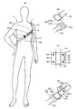
図1は、第1実施形態のバッグを示す正面図であり、図2は、図1に示すバッグの側面を模式的に示した図である。 FIG. 1 is a front view showing the bag of the first embodiment, and FIG. 2 is a view schematically showing a side surface of the bag shown in FIG.
図1に示すバッグ1は、袋体11と、ホルダ部材12と、ストラップ13を備えている。袋体11は、図2に示すように、第1胴111と、第2胴112と、底部113を有する。第1胴111と第2胴112は、ナイロン製であり、同じ形状であって同じ大きさである。第1胴111と第2胴112は、互いの左右両側どうしが縫い合わされており、第1胴111の下端部と第2胴112の下端部は、革製の底部113で結ばれている。すなわち、第1胴111と第2胴112の間に収納部110が設けられており、第1胴111の上縁と第2胴112の上縁の間が、収納部110につながる開口になる。この開口は、ファスナやボタン等の留め具によって閉じた状態を維持できるようにしてもよい。
The bag 1 shown in FIG. 1 includes a
図2には、この収納部110に荷物を詰め込み収納部110が膨らんだ状態のバッグ1が示されている。また、図2に示すバッグ1からは、ストラップ13が取り外されており、図2にはストラップは示されていない。第1胴111には第1持ち手116が取り付けられており、第2胴112には第2持ち手117が取り付けられている。図1は、第1胴111側から見た図であり、この図1には、第1持ち手116が第1胴111に縫い付けられた縫い目stが示されている。以下、第1持ち手116と第2持ち手117を総称して単に持ち手115と称する場合がある。持ち手115は、肩にかけることが可能な長さのものであり、本実施形態のバッグ1は、いわゆるトートバッグと呼ばれるものである。
FIG. 2 shows a bag 1 in which a
第1持ち手116と第2持ち手117は、図2に二点鎖線で示すように互いに離れているが、実線で示すようにホルダ部材12によって一つにまとめられる。ホルダ部材12は、第1持ち手116と第2持ち手117を重ね合わせた状態で、これらの持ち手に巻き付けられたものである。図1に示すバッグ1では、ホルダ部材12は、持ち手115の右側(バッグ1自身からすれば左側)の付け根部分に取り付けられているが、図2示すバッグ1では、ホルダ部材12は、持ち手115の一番高い位置に取り付けられている。ホルダ部材12は、持ち手115に沿って移動可能なものである。
The
図1に示すストラップ13は、長尺の帯状のものである。ホルダ部材12は、ストラップ13の幅W1よりも長い領域W2で持ち手115に接している。ホルダ部材12が持ち手115に接している領域W2は、ストラップ13の幅W1の3倍以上であるが、2倍以上であってもよい。
The
袋体11の底側の左右部分それぞれには、外向きにDカン118が取り付けられている。すなわち、Dカン118は、第1持ち手116の取り付け部分の下端部に外向きに取り付けられている。一方、ストラップ13の一端には、ナスカン131が設けられている。このナスカン131は、左右いずれか一方のDカン118に接続される。図1では、ナスカン131は、左側(バッグ1自身からすれば右側)のDカン118に接続されている。なお、図2に示すように、Dカン118は、第1胴111に取り付けられているが、第2胴112には取り付けられていない。図1に示すバッグ1の収納部110を背中側で固定する場合、第1胴111を背中側に向けることで、Dカン118とナスカン131の接続している箇所が見えなくなる。
D-
図1に示すストラップ13の他端、すなわち、ナスカン131が設けられた側とは反対側には、接続部132が設けられている。図1に示す接続部132は、凹部と凸部が長手方向に間隔をあけて設けられ、ループ状にして凹部と凸部を押し合わせて接続するスナップボタン(ホック)式のものである。ホルダ部材12には、スリット121が設けられている。接続部132は、ホルダ部材12に巻き掛けられ、このスリット121を通してループ状になり、スナップボタン1321によって留められることで、ホルダ部材12に接続している。図1に示すように、ストラップ13は、袋体11の底側とホルダ部材12を結んでいる。
A connecting
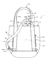
図3は、図1に示すバッグ1の収納部110を背中側で固定する例を模式的に示す図である。図3(a)は使用者Hを正面から示す図であり、同図(b)は使用者Hを背面から示す図である。
FIG. 3 is a diagram schematically showing an example in which the
図1に示すバッグ1は、ストラップ13を用いずに、持ち手115を肩にかけて使用することもできるが、それでは、持ち手115が肩からずり落ちることが気になる場合がある。また、収納部110が大きく揺れてしまうことが気になる場合もある。これらの場合には、ストラップ13を使用して、持ち手115が肩からずり落ちることを防止するとともに、使用者Hの体にバッグ1をフイットさせ収納部110の揺れも抑えることができる。
The bag 1 shown in FIG. 1 can be used by hanging the
まず、使用者Hは、左右どちらかの肩に持ち手をかける。この図3に示す例では、ホルダ部材12によって一つにまとめられた持ち手115が使用者Hの左肩LSにかけられている。持ち手115を左肩LSにかける場合には、図1に示すバッグ1のように、ストラップ13のナスカン131は、バッグ1自身からすれば右側のDカン118に接続しておく。一方、ストラップ13の接続部132は、ホルダ部材12に未接続の状態にしておく。また、ホルダ部材12は、持ち手の一番高い位置から、持ち手115の右側(バッグ1自身からすれば左側)の付け根部分の間に位置させておく。すなわち、持ち手115を使用者Hの左肩LSにかけた場合には、ホルダ部材12が正面側に位置するようにしておく。
First, the user H puts a handle on either the left or right shoulder. In the example shown in FIG. 3, the
図3(b)に示すように、Dカン118が設けられた第1胴111を使用者Hの背中BK側に向け、ストラップ13を、持ち手をかけた側とは反対側(この例では右側)の脇の下を通して、ストラップ13の接続部132が正面側にくるようにストラップ13を回し込む。袋体11の姿勢は、少し斜めの姿勢(袋体11自身からすれば右側の底部が右側に持ち上げられた斜めの姿勢)になる。使用者Hを後から見た場合、第2胴112が見えるだけであって、Dカン118は見えない。
As shown in FIG. 3B, the
ストラップ13の接続部132を、ホルダ部材12に巻き掛け、ホルダ部材12のスリット121を通してループ状にし、スナップボタン1321によって留める。
The
こうすることで、バッグ1の収納部110が背中側に固定される。ストラップ13の長さ、あるいはホルダ部材12の位置によって、持ち手115が内側(この例では右側)に引っ張られる程度は異なるが、持ち手115が内側に引っ張られていることで、持ち手115が肩から外側へずり落ちることが防止されている。また、袋体11は、斜めの姿勢になるほどストラップ13によって引っ張られており、収納部110が大きく揺れてしまうことも抑えられている。
By doing so, the
本実施形態のバッグ1によれば、ホルダ部材12が持ち手115に面で接することになり、点で接する場合よりも一箇所にかかる力が小さくなり、持ち手115が変形する場合であっても、持ち手115は広い範囲にわたって変形するため、1箇所において変形するよりも変形の程度は小さくてすみ、持ち手115が変形して肩に食い込むことを低減することができる。また、収納部110に重い荷物を収納しても、持ち手115が破損することも低減される。
According to the bag 1 of the present embodiment, the
また、ホルダ部材12は、持ち手115に沿って移動可能なものであるため、持ち手115に対するストラップ13の接続位置を、無段階に連続して容易に変えることができる。収納部110に収納された荷物の重さは、持ち手115に直接かかる下向きの力と、ホルダ部材12を介して持ち手115がストラップ13によって引っ張られる力とに分力される。ホルダ部材12を上の位置に取り付けた状態で、ストラップ13に多少の緩みを与えてバッグ1の収納部110を背中側に固定すると、使用者Hが動いていくうちに、持ち手115に直接かかる下向きの力と、持ち手115がストラップ13によって引っ張られる力とが最もバランスした位置にホルダ部材12が落ちていき、持ち手115が変形して肩に食い込むことをより低減することができる場合がある。
Further, since the
さらに、ホルダ部材12をできるだけ下方に取り付け、ストラップ13のうち胸側に位置する部分を下げることで、胸の周りにあるリンパ線を押さえることを避けることができる。また、女性の場合には、乳房を避けることができ、バッグ1を装着することの抵抗を無くすことができる。これらの場合、肩にかけた持ち手115の、第1胴111側の端部にホルダ部材12を取り付ければよく、持ち手115は長い方が好ましい。例えば、肩にかけた持ち手115の、第1胴111側の端部にホルダ部材12を取り付けた場合、胸側を走るストラップ13がほぼ水平(例えば、図3(a)の場合は145度程度であるが、160度以上180度以下が好ましい)になる程度の長さが持ち手115にあることが好ましい。
Further, by attaching the
加えて、ホルダ部材12によって、第1持ち手116と第2持ち手117は一つにまとめられ、持ち手全体としての強度が高まり、持ち手115が変形して肩に食い込むことがより低減される。また、ホルダ部材12によって第1持ち手116と第2持ち手117が一つにまとめられていれば、肩にかけた場合に一方の持ち手のみが肩からずり落ちることがなくなる。
In addition, the
図4は、図1に示すバッグ1の変形例を示す図である。以下、図1に示すバッグ1との相違点を中心に説明し、これまで説明した事項と重複する事項については説明を省略する場合がある。また、これまで説明した構成要素の名称と同じ名称の構成要素には、これまで付した符号と同じ符号を付して説明する。 FIG. 4 is a diagram showing a modified example of the bag 1 shown in FIG. Hereinafter, the differences from the bag 1 shown in FIG. 1 will be mainly described, and the description may be omitted for the matters overlapping with the matters described so far. Further, the components having the same names as the components described so far will be described with the same reference numerals as those given so far.
図4(a)は、変形例のバッグ1の持ち手115を左肩LSにかけ、背中側で収納部110を固定した使用者Hを正面から示す図である。
FIG. 4A is a front view showing the user H in which the
この変形例では、ストラップ13が、図1に示すストラップと異なる。図4(a)に示すストラップ13には、長さ調節部材133と、バックル134が設けられている。長さ調節部材133は、長方形の枠体と、枠体の短辺どうしを接続した、不図示の固定軸と出口軸1331が一体に成形された樹脂製のものである。以下、図4(a)に示す長さ調節部材133の、紙面手前側を表側といい、紙面奥側を裏側という。ストラップ13を構成するベルト体13aの一端側は、長さ調節部材133の固定軸に固定されており、他端側は、ナスカン131の取付リング131a(図1参照)に通された後、固定軸に表側から巻き掛けられ、次いで出口軸1331に裏側から巻き掛けられている。そして、ベルト体13aの他端は、出口軸1331を経てバックル134に固定されている。すなわち、長さ調節部材133の固定軸とナスカン131の取付リング131a(図1参照)の間は、ベルト体13aが二重構造になっており、固定軸とバックル134の間は、ベルト体13aは一重構造である。したがって、長さ調節部材133をナスカン131側に移動させると、二重構造部分が一重構造になってベルト体13aの長さは長くなる。反対に、長さ調節部材133をバックル134側に移動させると、一重構造部分が二重構造になってベルト体13aの長さは短くなる。
In this modification, the
図4(b)は、バックル134を示す図である。
FIG. 4B is a diagram showing the
バックル134は、ベルト体13aが固定された内側部1341と、接続部132が固定された外側部1342を有する連結部材である。内側部1341の先端側は、外側部1342の内側に収納される。内側部1341の先端1341tには磁石が配置されている。また、外側部1342の内側における、内側部1341の先端1341tと対向する部分にも磁石が配置されている。図4(b)に示す矢印のように、内側部1341をスライドさせることで、外側部1342との脱着が可能である。特に、連結時には磁力によって外側部1342と内側部1341は容易に連結される。
The
図4(c)は、図1に示すホルダ部材12を開いた状態で示す図である。この変形例におけるホルダ部材12も、図1に示すバッグ1におけるホルダ部材と同じである。ホルダ部材12は、基部12aと、凸部122が設けられた第1折返部12bと、凹部123が設けられた第2折返部12cを有する。なお、第1折返部12bに設けられた凸部122は、紙面奥側に向かって突出している。凹部123と凸部122でスナップボタンが構成されている。基部12aには、第1持ち手116と第2持ち手117が重ね合わされた状態で載置される。すなわち、基部12aには持ち手115が載置される。図4(c)では、持ち手115を二点鎖線で示している。第1折返部12bは、基部12aに載置された持ち手115に重ねられる部分である。したがって、基部12aと第1折返部12bが、持ち手115を挟み込み、持ち手115に接することになる。第2折返部12cは、その第1折返部12bに重ねられる部分である。第2折返部12cが第1折返部12bに重ねられることで、凹部123と凸部122が対向し、押し合わせて凹部123と凸部122を接続する。
FIG. 4C is a diagram showing the
第1持ち手116と第2持ち手117のうちのいずれか一方の持ち手に、基部12aを固定してもよいが、この例では、ホルダ部材12は、固定されておらず、持ち手115から取り外し自在である。ホルダ部材12もバッグ1のデザインの一部を構成するものである。持ち手115を肩にかけるのではなく手に持つ場合には、ホルダ部材12を取り外せば、全体的なイメージが少し変わったバッグとして使用することができるようになる。なお、基部12aに、第1持ち手116と第2持ち手117のうちのいずれか一方の持ち手のみを載置することもできる。ただし、持ち手が一つにまとまらず、載置しなかった方の持ち手は、載置した方の持ち手よりも外側(左肩にかけた場合には左側)にある場合には、肩からずり落ちる恐れがある。
The
図4(d)は、接続部132を示す図である。
FIG. 4D is a diagram showing the
図4(d)に示す接続部132の一端132tは、バックル134の外側部1342に固定されている。また、図4(d)に示す接続部132には、長手方向に間隔をあけて設けられた凸部1321aと凹部1321bが示されている。なお、図4(d)に示す凹部1321bは、紙面手前側に向かって凹んでいるが、図4(d)では凹んでいる様子は見えない。一方、図4(d)に示す凸部1321aは、紙面手前側に向かって突出している。接続部132は、ホルダ部材12に巻き掛けられ、ホルダ部材12のスリット121を通してループ状になり、凸部1321aと凹部1321bが対向し、押し合わせて凸部1321aと凹部1321bを接続する。図4(d)に示す接続部132によって、簡単な構造でストラップ13をホルダ部材12に接続させることができる。
One
図5は、第2実施形態のバッグを示す正面図である。以下においても、これまで説明したバッグ1との相違点を中心に説明し、これまで説明した事項と重複する事項については説明を省略する場合がある。また、これまで説明した構成要素の名称と同じ名称の構成要素には、これまで付した符号と同じ符号を付して説明する。 FIG. 5 is a front view showing the bag of the second embodiment. Also in the following, the differences from the bag 1 described so far will be mainly described, and the description may be omitted for the matters overlapping with the matters described so far. Further, the components having the same names as the components described so far will be described with the same reference numerals as those given so far.
図5に示すバッグ1における第1胴111には、第1持ち手116の左右それぞれにおける取り付け部の外側にファスナ111fが設けられている。このファスナ111fを開くと、収納部110につながっている。このファスナ111fを、図1に示すバッグ1や、図4に示す変形例のバッグ1に設けてもよい。
The
また、図5に示すバッグ1では、ストラップ13の接続部132の構造に特徴がある。図5に示す接続部132は、フック部材1322と係止環1323から構成されている。フック部材1322は、係止爪1322aと長さ調節部1322bを有する。ナスカン131の取付リング131aに一端が固定されたベルト体13bの他端は、この長さ調節部1322bの軸(不図示)に巻き掛けられて長さ調節部1322bに通されており、長さ調節部1322bから延びる他端部13b1の長さを調節することで、ベルト体13bの、取付リング131aと長さ調節部1322bとの間の長さを変えることができる。係止環1323は、ホルダ部材12に巻き掛けられ、ホルダ部材12のスリット121を通してループ状になっており、係止爪1322aが挿入できるだけの隙間が残されている。図5に示すバッグ1では、係止爪1322aが係止環1323に挿入され、係止爪1322aが係止環1323に係止されている。
Further, in the bag 1 shown in FIG. 5, the structure of the connecting
図6は、図5に示すバッグの変形例を示す図である。以下、図5に示すバッグ1との相違点を中心に説明し、これまで説明した事項と重複する事項については説明を省略する場合がある。また、これまで説明した構成要素の名称と同じ名称の構成要素には、これまで付した符号と同じ符号を付して説明する。 FIG. 6 is a diagram showing a modified example of the bag shown in FIG. Hereinafter, the differences from the bag 1 shown in FIG. 5 will be mainly described, and the description may be omitted for the matters overlapping with the matters described so far. Further, the components having the same names as the components described so far will be described with the same reference numerals as those given so far.
この変形例では、ストラップ13が、図5に示すストラップと異なる。図6に示すストラップ13の接続部132は、ナスカン1324と取付リング1325から構成されている。図6に示すストラップ13では、ベルト体13bの両端それぞれに、ナスカン131,1324と取付リング131a,1325が設けられている。そして、ホルダ部材12には、スリットの代わりにDカン124が設けられている。図6に示す接続部132を構成するナスカン1324は、このDカン124に接続されている。
In this modification, the
図7は、第3実施形態のバッグを示す正面図である。以下においても、これまで説明したバッグ1との相違点を中心に説明し、これまで説明した事項と重複する事項については説明を省略する場合がある。また、これまで説明した構成要素の名称と同じ名称の構成要素には、これまで付した符号と同じ符号を付して説明する。 FIG. 7 is a front view showing the bag of the third embodiment. Also in the following, the differences from the bag 1 described so far will be mainly described, and the description may be omitted for the matters overlapping with the matters described so far. Further, the components having the same names as the components described so far will be described with the same reference numerals as those given so far.
図7に示すバッグ1のストラップ13は、図4を用いて説明したストラップと同じく、バックル134が設けられている。ただし、図4(a)に示す長さ調節部材133は設けられていない。なお、この長さ調節部材133を設けてもよい。また、ストラップ13の接続部132も、図4(d)に示す接続部と同じ構造である。
The
図7に示すバッグ1では、ホルダ部材12が、持ち手115の、肩にかける部分をほぼ覆う程の長さをもった、いわゆるカバー状のものである。このカバー状のホルダ部材12は、ファスナ125を閉めることで持ち手115を覆う。図7に示すホルダ部材12には、持ち手115の長さ方向に沿って、複数の巻き掛け部126が設けられている。ストラップ13の接続部132は、この巻き掛け部126に通されることでホルダ部材12に巻き掛けられ、スナップボタン1321によって留められ、ホルダ部材12に接続している。図7に示すホルダ部材12は、これまで説明したホルダ部材よりも長い領域で持ち手115に接している。一方、持ち手115に対するストラップ13の接続位置は、これまでのホルダ部材12を用いた場合には、連続的に変更可能であった。すなわち、任意の位置にすることができた。一方、図7に示すホルダ部材12では、接続位置は予め決められた離散的な位置になる。
In the bag 1 shown in FIG. 7, the
本発明は上述の実施の形態に限られることなく特許請求の範囲に記載した範囲で種々の変更を行うことができる。例えば、第1持ち手116は、第1胴111と別体のものであったが、第1持ち手116と第1胴111は一体のものであってもよい。第2持ち手117も、第2胴112と別体のものであったが、第2持ち手117と第2胴112も一体のものであってもよい。また、底部113を省略し、第1胴111と第2胴112における互いの底縁どうしを縫い合わせてもよい。あるいは、第1胴111と第2胴112の間にマチ部を設けてもよい。また、ストラップ13の一端は、袋体11の底側に接続されているが、袋体11の底側とは、例えば、第1胴111の下半分部分であれば位置は限定されない。さらに、ストラップ13は、袋体11の底側を通って一端は、底部とは異なる場所に接続されていてもよい。すなわち、ストラップ13は、袋体11の底側と、持ち手115を結ぶものであればよく、ストラップ13の端部がどこに位置するかは限定されない。
The present invention is not limited to the above-described embodiment, and various modifications can be made within the scope of the claims. For example, the
なお、以上説明した実施形態や変形例の記載それぞれにのみ含まれている構成要件であっても、その構成要件を、他の実施形態や他の変形例に適用してもよい。例えば、ファスナ111fが設けられていない第1胴111にファスナ111fを設けてもよいし、長さ調節部材133が設けられていないストラップ13に長さ調節部材133を設けてもよいし、バックル134が設けられていないストラップ13にバックル134を設けてもよい。
It should be noted that even if the constituent requirements are included only in the description of the embodiment and the modified examples described above, the constituent requirements may be applied to other embodiments and other modified examples. For example, the
最後に、これまで説明したことを含めて、高品質なバッグであったり、スタイリッシュなバッグを提供するための技術的思想を、以下に付記する。 Finally, the technical ideas for providing high-quality bags and stylish bags, including those described so far, are added below.
(付記1)
肩にかけることが可能な持ち手が設けられた袋体と、
前記持ち手に取り付けられたホルダ部材と、
前記袋体の底側と前記ホルダ部材を結ぶストラップとを備え、
前記ホルダ部材は、前記持ち手に沿って移動可能なものであることを特徴とするバッグ。
(Appendix 1)
A bag with a handle that can be hung on the shoulder,
The holder member attached to the handle and
A strap connecting the bottom side of the bag body and the holder member is provided.
The holder member is a bag that can be moved along the handle.
(付記2)
肩にかけることが可能な持ち手が設けられた袋体と、
前記持ち手に取り付けられたホルダ部材と、
前記袋体の底側と前記ホルダ部材を結ぶストラップとを備え、
前記ホルダ部材は、前記持ち手から取り外し自在なものであることを特徴とするバッグ。
(Appendix 2)
A bag with a handle that can be hung on the shoulder,
The holder member attached to the handle and
A strap connecting the bottom side of the bag body and the holder member is provided.
The holder member is a bag that is removable from the handle.
(付記3)
肩にかけることが可能な持ち手が設けられた袋体と、
前記持ち手に取り付けられたホルダ部材と、
前記袋体の底側と前記ホルダ部材を結ぶストラップとを備え、
前記袋体は、第1胴と第2胴の間に収納空間を有するものであり、
前記持ち手は、前記第1胴に設けられた第1持ち手と、前記第2胴に設けられ、該第1持ち手とは離れた第2持ち手を含むものであり、
前記ホルダ部材は、前記第1持ち手と前記第2持ち手を一つにまとめることが可能なものであることを特徴とするバッグ。
(Appendix 3)
A bag with a handle that can be hung on the shoulder,
The holder member attached to the handle and
A strap connecting the bottom side of the bag body and the holder member is provided.
The bag body has a storage space between the first body and the second body.
The handle includes a first handle provided on the first body and a second handle provided on the second body and separated from the first handle.
The holder member is a bag characterized in that the first handle and the second handle can be combined into one.
(付記4)
前記ホルダ部材は、前記第1持ち手と前記第2持ち手のうちのいずれか一方の持ち手にのみ取り付けることも可能なものであることを特徴とする付記3に記載の記載のバッグ。
(Appendix 4)
The bag according to Appendix 3, wherein the holder member can be attached only to one of the first handle and the second handle.
付記1〜4に記載の技術的思想によれば、高品質なバッグであったり、スタイリッシュなバッグを提供することができる。
(付記5)
肩にかけることが可能な持ち手が設けられた袋体と、
前記持ち手に取り付けられたホルダ部材と、
前記袋体の底側と前記ホルダ部材を結ぶストラップとを備え、
前記ホルダ部材は、前記ストラップの幅よりも長い領域で前記持ち手に接しているものであることを特徴とするバッグ。
なお、前記ホルダ部材は、前記ストラップの幅よりも2倍以上長い領域で前記持ち手に接しているものであってもよい。
According to the technical idea described in the appendices 1 to 4, it is possible to provide a high-quality bag or a stylish bag.
(Appendix 5)
A bag with a handle that can be hung on the shoulder,
The holder member attached to the handle and
A strap connecting the bottom side of the bag body and the holder member is provided.
The bag is characterized in that the holder member is in contact with the handle in a region longer than the width of the strap.
The holder member may be in contact with the handle in a region that is twice or more longer than the width of the strap.
1 バッグ
11 袋体
110 収納部
111 第1胴
112 第2胴
113 底部
12 ホルダ部材
13 ストラップ
115 持ち手
116 第1持ち手
117 第2持ち手
W1 幅
W2 領域
1
Claims (4)
前記持ち手に取り付けられたホルダ部材と、
前記袋体の底側と前記ホルダ部材を結ぶストラップとを備え、
前記ホルダ部材は、前記ストラップの幅よりも長い領域で前記持ち手を覆ったものであって、該持ち手に沿って移動可能なものであり、
前記ストラップは、前記袋体の底側の左右いずれか一方側に付け替え自在なものであって、前記持ち手を使用者の左肩にかけ該袋体の一方側の胴を該使用者側にした状態では、該一方側の胴を正面視した場合に、該持ち手に沿って正面視右側に移動させた前記ホルダ部材と前記袋体の底側の正面視左側を結び、該持ち手を使用者の右肩にかけ該一方側の胴を該使用者側にした状態では、該一方側の胴を正面視した場合に、該持ち手に沿って正面視左側に移動させた該ホルダ部材と該袋体の底側の正面視右側を結ぶものであることを特徴とするバッグ。 A bag with a handle that can be hung on the shoulder,
The holder member attached to the handle and
A strap connecting the bottom side of the bag body and the holder member is provided.
The holder member, der that covers the possession in a region longer than the width of the strap is intended movable along the hand該持Chi,
The strap is freely replaceable on either the left or right side of the bottom side of the bag body, and the handle is hung on the left shoulder of the user and the body on one side of the bag body is on the user side. Then, when the body on one side is viewed from the front, the holder member moved to the right side in the front view along the handle is connected to the left side in the front view on the bottom side of the bag, and the handle is used by the user. When the one-sided body is placed on the right shoulder and the one-sided body is on the user side, the holder member and the bag are moved to the left side of the front view along the handle when the one-sided body is viewed from the front. A bag characterized by connecting the bottom side of the body to the right side of the front view.
前記持ち手は、前記第1胴に設けられた第1持ち手と、前記第2胴に設けられ、該第1持ち手とは離れた第2持ち手を含むものであり、
前記ホルダ部材は、前記第1持ち手と前記第2持ち手を一つにまとめるものであることを特徴とする請求項1又は2記載のバッグ。 The bag body has a storage space between the first body and the second body.
The handle includes a first handle provided on the first body and a second handle provided on the second body and separated from the first handle.
The bag according to claim 1 or 2 , wherein the holder member combines the first handle and the second handle into one.
前記ストラップは、前記ホルダ部材に巻き付けられたものであることを特徴とする請求項1乃至3のうちいずれか1項記載のバッグ。 The holder member is wound around the handle.
The bag according to any one of claims 1 to 3, wherein the strap is wound around the holder member.
Priority Applications (3)
| Application Number | Priority Date | Filing Date | Title |
|---|---|---|---|
| JP2020030298A JP6970463B2 (en) | 2020-02-26 | 2020-02-26 | bag |
| KR1020227027320A KR102594302B1 (en) | 2020-02-26 | 2021-02-26 | hundred |
| PCT/JP2021/007281 WO2021172497A1 (en) | 2020-02-26 | 2021-02-26 | Bag |
Applications Claiming Priority (1)
| Application Number | Priority Date | Filing Date | Title |
|---|---|---|---|
| JP2020030298A JP6970463B2 (en) | 2020-02-26 | 2020-02-26 | bag |
Publications (3)
| Publication Number | Publication Date |
|---|---|
| JP2021132808A JP2021132808A (en) | 2021-09-13 |
| JP2021132808A5 JP2021132808A5 (en) | 2021-10-21 |
| JP6970463B2 true JP6970463B2 (en) | 2021-11-24 |
Family
ID=77491219
Family Applications (1)
| Application Number | Title | Priority Date | Filing Date |
|---|---|---|---|
| JP2020030298A Active JP6970463B2 (en) | 2020-02-26 | 2020-02-26 | bag |
Country Status (3)
| Country | Link |
|---|---|
| JP (1) | JP6970463B2 (en) |
| KR (1) | KR102594302B1 (en) |
| WO (1) | WO2021172497A1 (en) |
Families Citing this family (1)
| Publication number | Priority date | Publication date | Assignee | Title |
|---|---|---|---|---|
| JP7554810B2 (en) | 2022-12-20 | 2024-09-20 | 株式会社三栄コーポレーション | Shoulder bag |
Family Cites Families (7)
| Publication number | Priority date | Publication date | Assignee | Title |
|---|---|---|---|---|
| FR2612382B1 (en) * | 1987-03-17 | 1989-06-30 | Rabenjamina Martin | BODY BAG AND PLATE NARROW TO THE BODY BY MEANS OF A BELT THROUGH A SHOULDER AND A BELT THROUGH THE BELLY, AND HAVING A SYSTEM FOR IMMOBILIZING ITS CONTENT |
| US5045423A (en) | 1990-06-01 | 1991-09-03 | Xerox Corporation | Toner and developer compositions with charge enhancing additives |
| JP3072144U (en) * | 2000-03-16 | 2000-10-06 | 昇男 下田 | bag |
| JP6309507B2 (en) | 2012-04-18 | 2018-04-11 | テルコム・ベンチャーズ・エルエルシー | System and method for location determination using a local area network |
| WO2015019996A1 (en) * | 2013-08-07 | 2015-02-12 | 株式会社クロンティップイノベーション | Bag |
| KR20150019996A (en) | 2013-08-14 | 2015-02-25 | 삼성전자주식회사 | Connector |
| JP6877967B2 (en) * | 2016-11-25 | 2021-05-26 | 株式会社クロンティップ | Bag with straps and straps |
-
2020
- 2020-02-26 JP JP2020030298A patent/JP6970463B2/en active Active
-
2021
- 2021-02-26 KR KR1020227027320A patent/KR102594302B1/en active IP Right Grant
- 2021-02-26 WO PCT/JP2021/007281 patent/WO2021172497A1/en active Application Filing
Also Published As
| Publication number | Publication date |
|---|---|
| KR20220119741A (en) | 2022-08-30 |
| WO2021172497A1 (en) | 2021-09-02 |
| JP2021132808A (en) | 2021-09-13 |
| KR102594302B1 (en) | 2023-10-25 |
Similar Documents
| Publication | Publication Date | Title |
|---|---|---|
| US8245825B2 (en) | System for cinching a resilient luggage case | |
| JP3067634U (en) | Shoulder bag | |
| KR101319665B1 (en) | Sling bag with strap fastening arrangement | |
| US9737122B1 (en) | Convertible backpack handbag | |
| US20100089958A1 (en) | Combination Beach Bag And Blanket Or Towel | |
| JP6970463B2 (en) | bag | |
| JP4941857B2 (en) | Bag with both shoulder and backpack functions | |
| JP6162243B2 (en) | bag | |
| US20220117334A1 (en) | Wearable towel foldable into a backpack | |
| JP2021112450A (en) | bag | |
| JP7097116B1 (en) | rain gear | |
| JP3138966U (en) | Folding bag | |
| JP3205055U (en) | bag | |
| JP4234775B1 (en) | Backpack belt attachment cover | |
| JP4530816B2 (en) | Shoulder bag | |
| JP2012192148A (en) | Bag and combined structure of bag | |
| JP3175195U (en) | Polymorphic bag | |
| CN221830048U (en) | Coat | |
| JP3077635U (en) | Rucksack bag | |
| JP3107823U (en) | Waist bag with rucksack | |
| JP2020039450A (en) | bag | |
| TWI592114B (en) | Backpack | |
| JP3099104U (en) | Shoulder straps and shoulder bags | |
| JP2021176425A (en) | bag | |
| JP3166587U (en) | Carry bag with shoulder belt |
Legal Events
| Date | Code | Title | Description |
|---|---|---|---|
| A521 | Request for written amendment filed |
Free format text: JAPANESE INTERMEDIATE CODE: A523 Effective date: 20210816 |
|
| A621 | Written request for application examination |
Free format text: JAPANESE INTERMEDIATE CODE: A621 Effective date: 20210816 |
|
| A871 | Explanation of circumstances concerning accelerated examination |
Free format text: JAPANESE INTERMEDIATE CODE: A871 Effective date: 20210816 |
|
| A131 | Notification of reasons for refusal |
Free format text: JAPANESE INTERMEDIATE CODE: A131 Effective date: 20210907 |
|
| A521 | Request for written amendment filed |
Free format text: JAPANESE INTERMEDIATE CODE: A523 Effective date: 20211005 |
|
| TRDD | Decision of grant or rejection written | ||
| A01 | Written decision to grant a patent or to grant a registration (utility model) |
Free format text: JAPANESE INTERMEDIATE CODE: A01 Effective date: 20211019 |
|
| A61 | First payment of annual fees (during grant procedure) |
Free format text: JAPANESE INTERMEDIATE CODE: A61 Effective date: 20211022 |
|
| R150 | Certificate of patent or registration of utility model |
Ref document number: 6970463 Country of ref document: JP Free format text: JAPANESE INTERMEDIATE CODE: R150 |