JP6970193B2 - Electric shaver - Google Patents
Electric shaver Download PDFInfo
- Publication number
- JP6970193B2 JP6970193B2 JP2019515923A JP2019515923A JP6970193B2 JP 6970193 B2 JP6970193 B2 JP 6970193B2 JP 2019515923 A JP2019515923 A JP 2019515923A JP 2019515923 A JP2019515923 A JP 2019515923A JP 6970193 B2 JP6970193 B2 JP 6970193B2
- Authority
- JP
- Japan
- Prior art keywords
- cutter element
- handle
- cutter
- shaver head
- axis
- Prior art date
- Legal status (The legal status is an assumption and is not a legal conclusion. Google has not performed a legal analysis and makes no representation as to the accuracy of the status listed.)
- Active
Links
Images


Classifications
-
- B—PERFORMING OPERATIONS; TRANSPORTING
- B26—HAND CUTTING TOOLS; CUTTING; SEVERING
- B26B—HAND-HELD CUTTING TOOLS NOT OTHERWISE PROVIDED FOR
- B26B19/00—Clippers or shavers operating with a plurality of cutting edges, e.g. hair clippers, dry shavers
- B26B19/02—Clippers or shavers operating with a plurality of cutting edges, e.g. hair clippers, dry shavers of the reciprocating-cutter type
- B26B19/04—Cutting heads therefor; Cutters therefor; Securing equipment thereof
- B26B19/048—Complete cutting head being movable
-
- B—PERFORMING OPERATIONS; TRANSPORTING
- B26—HAND CUTTING TOOLS; CUTTING; SEVERING
- B26B—HAND-HELD CUTTING TOOLS NOT OTHERWISE PROVIDED FOR
- B26B19/00—Clippers or shavers operating with a plurality of cutting edges, e.g. hair clippers, dry shavers
- B26B19/02—Clippers or shavers operating with a plurality of cutting edges, e.g. hair clippers, dry shavers of the reciprocating-cutter type
- B26B19/04—Cutting heads therefor; Cutters therefor; Securing equipment thereof
- B26B19/046—Cutters being movable in the cutting head
Landscapes
- Life Sciences & Earth Sciences (AREA)
- Forests & Forestry (AREA)
- Engineering & Computer Science (AREA)
- Mechanical Engineering (AREA)
- Dry Shavers And Clippers (AREA)
Description
本発明は、角度位置を皮膚輪郭に自己適合することができるシェーバーヘッドを有する電気シェーバーに関する。より詳細には、本発明は、ハンドルと、少なくとも1つの駆動可能なカッター要素を含むシェーバーヘッドと、を備える電気シェーバーであって、シェーバーヘッドが、旋回及び/又は傾動軸を提供する支持構造体によってハンドルに接続され、カッター要素を含むシェーバーヘッドがそれを中心にハンドルに対して旋回又は傾動し得、カッター要素が、カッター振動軸に沿って、振動様式で駆動ユニットにより駆動可能であり、駆動ユニットが、カッター要素に結合された細長い駆動伝達器を含む、電気シェーバーに関する。 The present invention relates to an electric shaver having a shaver head capable of self-adapting an angular position to the skin contour. More specifically, the present invention is an electric shaver comprising a handle and a shaver head comprising at least one driveable cutter element, wherein the shaver head provides a swivel and / or tilt axis support structure. Connected to the handle by, the shaver head containing the cutter element can swivel or tilt with respect to the handle around it, the cutter element can be driven and driven by the drive unit in a vibrating manner along the cutter vibration axis. The unit relates to an electric shaver, including an elongated drive transmitter coupled to a cutter element.
電気シェーバーは、通常、電気駆動ユニットによって、カッター要素がせん断フォイル下で往復運動する振動様式で駆動される1つ以上のカッター要素を有し、このようなカッター要素又はアンダーカッターは、細長い形状を有している場合があり、それらの長手方向軸に沿って往復運動し得る。他の種類の電気シェーバーでは、振動様式又は連続様式で駆動され得る回転カッター要素を用いている。電気駆動ユニットは、電気モータ又は磁気式リニアモータを含み得、駆動ユニットは、モータの駆動運動をカッター要素に伝達するための細長い駆動伝達器などの要素を有する駆動トレインを含み得、モータは、シェーバーのハンドル部分内、又は代替的にそのシェーバーヘッド内に受けられ得る。 An electric shaver usually has one or more cutter elements driven by an electric drive unit in a vibration mode in which the cutter elements reciprocate under shear foil, such cutter elements or undercutters having an elongated shape. They may have and may reciprocate along their longitudinal axis. Other types of electric shavers use rotary cutter elements that can be driven in a vibrating or continuous fashion. The electric drive unit may include an electric motor or a magnetic linear motor, the drive unit may include a drive train having elements such as an elongated drive transmitter for transmitting the drive motion of the motor to the cutter element, and the motor may include. It can be received in the handle portion of the shaver, or in its alternative shaver head.
駆動ユニット及び駆動トレインの構造によらず、カッター要素、更に、前述の切断動作は、剃られる皮膚の輪郭に自己適合するように他の方向に移動可能であり得る。例えば、カッター要素は、シェーバーのハンドルに対して1つ以上の軸を中心に回転可能であるシェーバーヘッドの部分であってもよく、シェーバーヘッドをハンドルに接続する支持構造体は、シェーバーヘッドが細長いカッター要素に実質的に平行に延在する旋回軸及び/又はその往復運動軸を中心に旋回することを可能にし得る。加えて又は代替的に、支持構造体は、シェーバーヘッドがハンドルの長手方向軸に対して横方向、並びに細長いカッター要素及び/又はその往復運動軸に対して横方向に延在する傾動軸を中心に傾動することを可能にし得る。このようなシェーバーヘッドの動きに加えて又は代替的に、カッター要素は、剃られる皮膚輪郭に対してその位置を調節するように、シェーバーヘッドに潜り込み得る。 Regardless of the structure of the drive unit and drive train, the cutter element, as well as the aforementioned cutting action, may be movable in other directions to self-fit to the contour of the skin to be shaved. For example, the cutter element may be a portion of the shaver head that is rotatable about one or more axes with respect to the handle of the shaver, and the support structure that connects the shaver head to the handle has an elongated shaver head. It may be possible to swivel around a swivel axis extending substantially parallel to the cutter element and / or a reciprocating axis thereof. In addition or alternative, the support structure is centered on a tilting axis in which the shaver head extends laterally with respect to the longitudinal axis of the handle and laterally with respect to the elongated cutter element and / or its reciprocating axis. It may be possible to tilt to. In addition to or as an alternative to such shaver head movement, the cutter element may sneak into the shaver head to adjust its position relative to the skin contour to be shaved.
ハンドルに対するシェーバーヘッド及びそのカッター要素の回転運動による、モータからカッター要素への駆動運動の伝達は、特に、駆動ユニットが、ハンドルに対する、したがってハンドル内のモータに対するカッター要素の傾動及び/又は旋回運動を補正するのに必要である、ハンドルに収容され、駆動トレインを介してシェーバーヘッド内のカッター要素に接続されたモータを含む場合に、時々困難である。このような補正は、駆動トレイン及びハンドルと固定的に整列された駆動トレインの部分とのカッター要素の結合の位置ずれを許容する、駆動トレイン内の可撓性要素によって達成され得る。別の補正手法は、例えば、長孔等のスロット状凹部に受けられた駆動ピンなどの結合部内に遊びを提供する。しかし、可撓性要素又は遊びを介した傾動又は旋回運動のこのような補正は、動力伝達の効率を低下させ、達成可能な振動周波数を制限する。 The transmission of drive motion from the motor to the cutter element by the rotational motion of the shaver head and its cutter element with respect to the handle, in particular, causes the drive unit to tilt and / or swivel the cutter element with respect to the handle and thus to the motor within the handle. It is sometimes difficult to include a motor that is housed in a handle and connected to a cutter element in the shaver head via a drive train, which is necessary to compensate. Such corrections may be achieved by a flexible element within the drive train that allows misalignment of the coupling of the cutter element with the drive train and the portion of the drive train that is fixedly aligned with the handle. Another correction technique provides play in the coupling, such as a drive pin received in a slot-like recess, such as an elongated hole. However, such correction of tilting or turning motion through flexible elements or play reduces the efficiency of power transmission and limits the achievable vibration frequency.
例えば、米国特許出願公開第2009/0025229(A1)号は、せん断フォイルの下に設けられ、カッター振動軸に沿って振動様式で駆動される一対のカッター要素を有する電気シェーバーであって、シェーバーヘッド内に延在する伝達ピンの振動駆動運動が、シェーバーヘッド内の振動往復運動を支持する振動ブリッジを介してカッター要素上に加えられ、振動ブリッジが、カッター要素の調節する動きを補正するための曲がりやすい結合アームを含む、電気シェーバーを開示する。しかし、振動ブリッジのやや複雑な形状により、伝達構造は、やや複雑で、嵩高で洗浄が困難である。また、振動ブリッジの降伏構造は、カッター要素の高い周波数の振動を実現するのに電力を消費し、不利益である。 For example, US Patent Application Publication No. 2009/0025229 (A1) is an electric shaver provided under a shear foil and having a pair of cutter elements driven in a vibration mode along a cutter vibration axis, the shaver head. The vibration-driven motion of the transmission pin extending inward is applied onto the cutter element via a vibration bridge that supports the vibration reciprocating motion in the shaver head, for the vibration bridge to compensate for the adjusting movement of the cutter element. Disclose an electric shaver, including a flexible coupling arm. However, due to the slightly complicated shape of the vibrating bridge, the transmission structure is rather complicated, bulky and difficult to clean. Also, the yield structure of the vibration bridge consumes power to achieve high frequency vibration of the cutter element, which is disadvantageous.
枢動型の振動ブリッジを含む同様の伝達構造が、米国特許第7,841,090(B2)号から公知である。 Similar transmission structures, including pivotal vibrating bridges, are known from US Pat. No. 7,841,090 (B2).
シェーバーヘッドにおいて利用可能な限られた空間及びこのような振動ブリッジのやや嵩高な構造に起因して、シェーバーヘッドの回転を可能にする駆動トレインと支持構造体との衝突を回避することがまた困難である。もちろん、このような駆動トレインは、大幅に小型化することができ、位置ずれの補正は、シェーバーヘッドにモータを含む全体的な駆動ユニットを収容することによって容易に回避することができる。しかし、このような手法は、シェーバーヘッドの重量を大幅に増加し、そのため、輪郭に対するその応答性を変化させ、更に、シェーバーの操作性が不平衡質量により損なわれる。ハンドルからシェーバーヘッド内に延在する駆動トレインとのこのような衝突を回避するために、シェーバーヘッドの支持構造体を小型化する試みがされてきた。シェーバーヘッドをハンドルに接続するこのような支持構造体は、前述の旋回及び/又は傾動運動を可能にし、駆動ユニットからカッター要素に延在する駆動トレインとの衝突を回避するような異なる構成を有していてもよい。例えば、従来技術の参照米国特許出願公開第2010/0175264(A1)号は、ハンドルに対するシェーバーヘッドの四継手連結機構を示し、ここにおいて、リンクアームは、一種の振り子配置又は吊り下げ配置である。ハンドルに取り付けられるインターポーザ部は、シェーバーヘッド内に上方に突出する2つのポールを含み、リンクアームは、そのようなポールの上端部に枢着されて、ハンドルに向かって延在し、又は後下方に吊り下がる。このような吊りリンクアームの下端部は、シェーバーヘッドフレームに枢動可能に接続されている。 Due to the limited space available in the shaver head and the rather bulky construction of such a vibrating bridge, it is also difficult to avoid collisions between the drive train and the support structure that allow the shaver head to rotate. Is. Of course, such a drive train can be significantly reduced in size, and misalignment correction can be easily avoided by accommodating the entire drive unit, including the motor, in the shaver head. However, such an approach significantly increases the weight of the shaver head, thus changing its responsiveness to contours, and further impairs shaver operability due to unbalanced mass. Attempts have been made to reduce the size of the shaver head support structure in order to avoid such collisions with the drive train extending from the steering wheel into the shaver head. Such a support structure connecting the shaver head to the handle has different configurations to allow the aforementioned swivel and / or tilt motion and avoid collisions with the drive train extending from the drive unit to the cutter element. You may be doing it. For example, U.S. Patent Application Publication No. 2010/0175264 (A1), a prior art reference, describes a shaver head four-joint coupling mechanism to a handle, where the link arm is a type of pendulum or suspension arrangement. The interposer section attached to the handle contains two poles that project upward into the shaver head, and the link arm is pivoted to the upper end of such pole and extends towards the handle or posteriorly downward. Suspended in. The lower end of such a hanging link arm is pivotally connected to the shaver head frame.
電気シェーバーのシェーバーヘッドをそのハンドルに移動可能に接続する同様の支持構造体が、一対の吊りリンクアームを含む四継手連結機構を更に示す出願公開第2016−77464号を参照して示される。 A similar support structure that movably connects the shaver head of an electric shaver to its handle is shown with reference to Publication No. 2016-77464 further comprising a four-joint coupling mechanism comprising a pair of suspension link arms.
旋回及び傾動軸を中心とした電気シェーバーのシェーバーヘッドの旋回及び傾動を可能にする別のシェーバーが、クレードル状のハンドル部に枢動可能に装着され、一方では、カッター要素が支持されるカッターフレームを枢動可能に支持するシェーバーヘッドフレームを含むカルダン支持構造体を示唆する欧州特許第2435218(B1)号により示される。 Another shaver that allows the shaver head of the electric shaver to swivel and tilt around the swivel and tilt axis is pivotally mounted on the cradle-shaped handle, while the cutter frame supports the cutter element. 2435218 (B1) suggests a cardan support structure comprising a shaver head frame that pivotally supports the.
更に、オーストリア特許第409604(B)号は、カッター要素を有する電気シェーバーを示し、これは、振動切断動作に加えて、剃られる皮膚に対するカッター要素位置の調節及びシェーバーハウジングの長手方向軸に平行な軸を中心とする回転振動を可能にするように、シェーバーの長手方向軸に垂直な軸及びカッター要素の振動軸を中心として枢動することができる。駆動モータをカッター要素に接続する伝達トレインは、シェーバーハウジングの長手方向軸に平行な枢動軸を中心に回転振動する結合構造を含む。 Further, Austrian Patent No. 409604 (B) describes an electric shaver with a cutter element, which, in addition to vibrating cutting action, adjusts the position of the cutter element with respect to the skin to be shaved and is parallel to the longitudinal axis of the shaver housing. It can be pivoted around an axis perpendicular to the longitudinal axis of the shaver and the vibration axis of the cutter element to allow rotational vibration around the axis. The transmission train connecting the drive motor to the cutter element includes a coupling structure that rotationally vibrates about a pivot axis parallel to the longitudinal axis of the shaver housing.
米国特許出願公開第2009/0025229(A1)号は、電気シェーバーのカッター要素のための駆動ユニットを開示し、この駆動ユニットは、シェーバーヘッドに向かってシェーバーハウジングから延在する伝達ピンを含み、伝達ピンの振動駆動運動は、シェーバーヘッドにおける振動往復運動のために支持された振動ブリッジを介してカッター要素に加えられ、振動ブリッジは、カッター要素の調節運動を可能にするような降伏結合アームを含む。同様の伝達構造が、米国特許第7,841,090(B2)号から知られている。 US Patent Application Publication No. 2009/0025229 (A1) discloses a drive unit for the cutter element of an electric shaver, the drive unit comprising a transmission pin extending from the shaver housing towards the shaver head and transmitting. Vibration-driven motion of the pin is applied to the cutter element via a vibrating bridge supported for vibrating reciprocating motion in the shaver head, which includes a yield coupling arm that allows the cutter element to adjust. .. Similar transmission structures are known from US Pat. No. 7,841,090 (B2).
カッター要素の適応運動を可能にする更なる電気シェーバーが、米国特許第3,748,371(B)号、フランス特許第1391957(A)号、イギリス特許第811,207(B)号、及び米国特許第5,704,126(B)号から知られている。 Additional electric shavers that allow adaptive movement of the cutter element are US Pat. No. 3,748,371 (B), French Patent No. 1391957 (A), UK Pat. No. 811,207 (B), and the United States. It is known from Pat. No. 5,704,126 (B).
本発明の基礎をなす目的は、従来技術の不利点の少なくとも1つを回避する、及び/又は既存の解決方法を更に発展させる改善された電気シェーバーを提供することである。本発明の基礎をなすより具体的な目的は、ハンドルに対して回転可能なシェーバーヘッドの少なくとも1つのカッター要素に駆動ユニットの動作を伝達するための改善された伝達構造であって、伝達構造体の電力散逸が低く、高い周波数が達成可能であり、カッター要素が、駆動ユニットの駆動動作への直接応答を示す、伝達構造を提供することである。 An object underlying the present invention is to provide an improved electric shaver that avoids at least one of the disadvantages of prior art and / or further develops existing solutions. A more specific object underlying the present invention is an improved transmission structure for transmitting the movement of a drive unit to at least one cutter element of a shaver head that is rotatable with respect to a handle. The power dissipation is low, high frequencies are achievable, and the cutter element provides a transfer structure that exhibits a direct response to the drive operation of the drive unit.
本発明の基礎をなす別の目的は、シェーバーヘッドをハンドルに接続して、シェーバーヘッドがその位置でハンドルに対して自己調節することを可能する、及びカッター要素を駆動する駆動トレインと駆動トレインに制限されていない支持構造体との間の衝突を回避する改善された駆動トレイン構造及び支持構造体を提供することである。 Another object underlying the present invention is to connect a shaver head to a handle to allow the shaver head to self-adjust with respect to the handle in its position, and to drive trains and drive trains to drive cutter elements. It is to provide an improved drive train structure and support structure that avoids collisions with unrestricted support structures.
本発明の基礎をなす更なる目的は、剃られる皮膚輪郭に対するシェーバーヘッドの角度位置のよりよい自己調節を可能にし、ただし、依然として、小さな圧力が皮膚輪郭に接触する機能性シェーバーヘッド表面に加えられた状態で剃られる皮膚輪郭に沿ってシェーバーヘッドが運動したときに変化する皮膚輪郭に対するシェーバーヘッドの自己調節旋回及び傾動運動の良好な応答性、並びに/又はより小さな復元力でシェーバーヘッドの中立位置への迅速な再調節を含み、同時に、高い駆動周波数が達成可能であるカッター要素の効率的な駆動を達成することである。 A further object underlying the present invention allows better self-adjustment of the angular position of the shaver head with respect to the skin contour to be shaved, but still a small pressure is applied to the functional shaver head surface in contact with the skin contour. Good responsiveness of the shaver head's self-regulating swivel and tilt movements to the skin contour that changes as the shaver head moves along the skin contour that is shaved while being shaved, and / or the neutral position of the shaver head with less resilience. Including rapid readjustment to, at the same time, achieving efficient drive of the cutter element where high drive frequencies are achievable.
前述の目的の少なくとも1つを達成するために、電気シェーバーは、細長い駆動伝達器とカッター要素との間のいくつかの振動降伏ブリッジ構造を避けて、細長い駆動伝達器を少なくとも1つのカッター要素に直接結合することを提供し得る。より詳細には、細長い駆動送信器は、互いに垂直及び細長い駆動伝達器の長手方向軸に対して横方向に延在する一対の枢動軸を提供する枢動継手によって、カッター要素に結合され得る。切断振動に対する横方向へのカッター要素の自己調節の運動を可能にするために、枢動継手は、カッター要素に対して、カッター振動軸及び細長い駆動伝達器の長手方向軸に対して横方向の第1の方向における、そして更に、細長い駆動伝達器及び/又はカッター要素に対して、細長い駆動伝達器の長手方向軸に対して実質的に平行な第2の方向における、枢動継手の変位を可能にするように、細長い駆動伝達器及び/又はカッター要素に対して変位可能に装着され得る。 To achieve at least one of the aforementioned objectives, the electric shaver avoids several vibration yield bridge structures between the elongated drive transmitter and the cutter element, making the elongated drive transmitter into at least one cutter element. May provide direct binding. More specifically, the elongated drive transmitter may be coupled to the cutter element by a pivot joint that provides a pair of pivot axes that extend perpendicular to each other and laterally with respect to the longitudinal axis of the elongated drive transmitter. .. To allow lateral self-regulating movement of the cutter element with respect to cutting vibration, the pivot joint is lateral to the cutter element with respect to the cutter vibration axis and the longitudinal axis of the elongated drive transmitter. Displacement of the pivot joint in the first direction, and further in a second direction substantially parallel to the longitudinal axis of the elongated drive transmitter with respect to the elongated drive transmitter and / or cutter element. It can be displaceably mounted with respect to elongated drive transmitters and / or cutter elements to allow.
それにもかかわらず、枢動継手は、カッター振動軸の方向に、細長い駆動伝達器及びカッター要素に固定して装着されている。換言すれば、枢動継手は、基本的にカッター振動軸の方向に全く遊びなく細長い駆動伝達器をカッター要素に接続し、一方では、枢動継手は、前述の第1及び第2の方向での細長い駆動伝達器のカッター要素に対する変位を可能にし、このような実行可能な変位は、製造公差による単なる通常の遊びを超えるものである。例えば、第1及び第2の方向で実行可能な変位は、カッター要素の往復運動又は振動の振幅の25%以上であってもよい。第1及び第2の方向での変位を可能にする枢動継手の可動性は、前述の枢動軸及び/又は旋回軸を中心とするカッター要素を含むシェーバーヘッドの回転に起因する駆動伝達器に対するカッター要素の運動の補正を許容する範囲に与えられる。 Nevertheless, the pivot joint is fixedly mounted to the elongated drive transmitter and cutter element in the direction of the cutter vibration axis. In other words, the pivot joint connects the elongated drive transmitter to the cutter element, essentially with no play in the direction of the cutter vibration axis, while the pivot joint is in the first and second directions described above. Allows displacement of the elongated drive transmitter with respect to the cutter element, and such feasible displacement is more than just normal play due to manufacturing tolerances. For example, the displacement that can be performed in the first and second directions may be 25% or more of the amplitude of the reciprocating motion or vibration of the cutter element. The mobility of the pivot joint that allows displacement in the first and second directions is due to the rotation of the shaver head including the cutter element around the pivot axis and / or the swivel axis described above. It is given to the extent that the correction of the movement of the cutter element with respect to is allowed.
細長い駆動伝達器のカッター要素への直接的な枢動可能な接続は、伝達トレインの低電力散逸と、細長い駆動伝達器の駆動運動に対するカッター要素の直接的な応答とを達成すること、したがって、高い振動周波数を可能にすることを助けることができる。細長い駆動伝達器は、カッター要素に、又はその中に延在する剛直な構造体を形成し、カッター要素を直接的に押して、及び/又は引いて切断運動を達成し得る。細長い駆動伝達器をカッター要素に結合する枢動継手は、駆動伝達器に対するカッター要素の傾動及び/又は旋回を可能にし、駆動伝達器及び/又はカッター要素への枢動継手の摺動可能な装着は、細長い駆動伝達器とカッター要素との間の遊びなく、及びカッター要素の振動の方向の駆動トレインの可撓性がなく振動軸に沿った駆動動作の直接的な伝達が実行可能であるにもかかわらず、カッター要素が駆動伝達器に対して傾動又は回転する中心である軸の位置ずれに起因する駆動伝達器に対するカッター要素の運動の補正を可能にする。 A direct pivotable connection of the elongated drive transmitter to the cutter element achieves low power dissipation of the transmission train and a direct response of the cutter element to the drive motion of the elongated drive transmitter, therefore. It can help enable high vibration frequencies. The elongated drive transmitter may form a rigid structure extending into or within the cutter element and may achieve cutting motion by pushing and / or pulling the cutter element directly. A pivot joint that connects an elongated drive transmitter to the cutter element allows the cutter element to tilt and / or turn with respect to the drive transmitter, and a slidable attachment of the pivot joint to the drive transmitter and / or cutter element. There is no play between the elongated drive transmitter and the cutter element, and there is no flexibility of the drive train in the direction of vibration of the cutter element so that direct transmission of drive motion along the axis of vibration is feasible. Nevertheless, it allows correction of the movement of the cutter element with respect to the drive transmitter due to misalignment of the axis at which the cutter element tilts or rotates with respect to the drive transmitter.
これら及び他の優位点は、図面及び可能な例に言及する以下の説明から明らかになる。 These and other advantages become apparent from the drawings and the following description referring to possible examples.
カッター振動軸に沿った少なくとも1つのカッター要素の瞬間的な遊びのない駆動を達成するだけでなく、傾動及び/又は旋回軸を中心とするカッター要素の自己調節運動を可能にして、皮膚輪郭に対するカッター要素の自己適合及び皮膚輪郭に対するハンドピースの位置ずれの補正を達成するために、駆動トレインは、細長い駆動伝達器とカッター要素との間のいくつかの降伏振動ブリッジを有さなくてもよく、しかし、細長い駆動伝達器は、カッター要素に延在する剛直な構造体を形成し得、枢動継手によってカッター要素に直接接続され得、枢動継手は、細長い駆動伝達器に対するカッター要素の自由軸及び/又は運動軸のみを形成することができる。 Not only does it achieve momentary playless drive of at least one cutter element along the cutter vibration axis, but it also allows for self-regulating movement of the cutter element around the tilt and / or swivel axis, with respect to the skin contour. To achieve self-adaptation of the cutter element and correction of handpiece misalignment with respect to skin contours, the drive train may not have some yield vibration bridge between the elongated drive transmitter and the cutter element. However, the elongated drive transmitter can form a rigid structure extending to the cutter element and can be directly connected to the cutter element by a pivot joint, the pivot joint is the freedom of the cutter element to the elongated drive transmitter. Only axes and / or motion axes can be formed.
枢動継手は、伝達トレインの単なる構造要素又はスポットであってもよく、カッター要素は、駆動ユニットのモータからカッター要素に延在する剛直な非降伏構造を形成し得る細長い駆動伝達器に対して移動することができる。 The pivot joint may be merely a structural element or spot in the transmission train, where the cutter element is for an elongated drive transmitter that can form a rigid, non-yielding structure extending from the motor of the drive unit to the cutter element. You can move.
一方でカッター振動軸に沿った切断運動に関して低損失である堅い伝達特性を達成し、他方でその他の軸に沿った及び/又はそれらを中心としたカッター要素の自己適合を可能にするために、枢動継手は、カッター振動軸の方向でのカッター要素及び駆動伝達器に対して少なくとも実質的にいずれの遊びもなくなるように適合され得、具体的には、枢動継手と細長い駆動伝達器及びカッター要素との係合が、カッター振動軸の方向で遊びがなくなるように適合され得る。一方では、枢動継手は、振動軸以外の変位軸に沿った可動性を提供し、及び/又は1つ以上の枢動軸を中心に枢動する自由度を提供するように適合されてもよい。 On the one hand, to achieve rigid transmission characteristics with low loss for cutting motion along the axis of vibration of the cutter, and on the other hand, to allow self-fitting of the cutter elements along and / or around them on the other axis. The pivot joint can be adapted so that there is at least virtually no play with respect to the cutter element and drive transmitter in the direction of the cutter vibration axis, specifically the pivot joint and the elongated drive transmitter and The engagement with the cutter element can be adapted so that there is no play in the direction of the cutter vibration axis. On the one hand, even if the pivot joint is adapted to provide mobility along a displacement axis other than the vibration axis and / or to provide the freedom to pivot around one or more pivot axes. good.
より詳細には、剛直な駆動伝達器をカッター要素に接続する枢動継手は、駆動伝達器の長手方向軸に実質的に平行な方向で、駆動伝達器に対して、及び/又はカッター要素に対して摺動し得る。これにより、カッター要素は、駆動伝達器に沿って上下に運動し、これにより枢動継手を経由していない軸を中心にシェーバーヘッド、したがってカッター要素が回転したときに、駆動伝達器の長手方向軸の方向のカッター要素の各運動を補正することができる。例えば、シェーバーヘッドが駆動伝達器の長手方向軸及び振動軸に対して横方向に延在する傾動軸を中心に傾動している場合には、傾動軸は、カッター要素、加えてその角度運動が駆動伝達器の長手方向軸の方向に移動するように、駆動伝達器をカッター要素に接続する枢動継手から離間されてもよい。このような動きは、駆動伝達器の長手方向軸の方向における、駆動伝達器に対する及び/又はカッター要素に対する枢動継手の可動性によって補正され得る。同様に、振動軸とほぼ平行に延在するがそれから離間している旋回軸を中心にシェーバーヘッドが旋回運動する場合には、カッター要素、更に旋回によるそれらの角度運動はまた、駆動伝達器の長手方向軸の方向に移動されてもよい。旋回軸は、例えば2つのカッター要素の間にロングヘアーカッターなどの追加の機能要素が設けられうる場合などの異なる理由のために、枢動継手から離間されてもよい。このようなマルチカッターシェーバーヘッドのために、旋回軸は、駆動伝達器をカッター要素に接続する枢動継手が旋回軸から離間され得るように2つのカッター要素間の平面に延在することができる。 More specifically, the pivot joint connecting the rigid drive transmitter to the cutter element is substantially parallel to the longitudinal axis of the drive transmitter, to the drive transmitter and / or to the cutter element. Can slide against. This causes the cutter element to move up and down along the drive transmitter, thereby in the longitudinal direction of the drive transmitter when the shaver head, and thus the cutter element, rotates around an axis that does not go through the pivot joint. Each movement of the cutter element in the direction of the axis can be corrected. For example, if the shaver head is tilted about a tilt axis that extends laterally with respect to the longitudinal axis and vibration axis of the drive transmitter, the tilt axis is the cutter element, plus its angular motion. The drive transmitter may be separated from the pivot joint connecting the cutter element so as to move in the direction of the longitudinal axis of the drive transmitter. Such movement may be compensated for by the mobility of the pivot joint with respect to the drive transmitter and / or with respect to the cutter element in the direction of the longitudinal axis of the drive transmitter. Similarly, if the shaver head swivels around a swivel axis that extends approximately parallel to, but away from it, the cutter element, as well as those angular movements due to swivel, are also of the drive transmitter. It may be moved in the direction of the longitudinal axis. The swivel shaft may be separated from the pivot joint for different reasons, for example if additional functional elements such as a long hair cutter may be provided between the two cutter elements. For such a multi-cutter shaver head, the swivel shaft can extend in a plane between the two cutter elements so that the pivot joint connecting the drive transmitter to the cutter element can be separated from the swivel shaft. ..
駆動伝達器の長手方向軸の方向において駆動伝達器に対して、及び/又はカッター要素に対して枢動継手が潜り込むことを可能にする前述の自由度に加えて、枢動継手には、駆動伝達器の長手方向軸に対して実質的に横及び振動軸に対して実質的に横の方向において、駆動伝達器に対する及び/又はカッター要素に対する枢動継手の変位を可能にする追加的な自由度が提供され得る。このような横方向の自由度は、駆動伝達器からカッター要素への駆動力の伝達を損なうことなく、振動軸と平行に延在する前述の旋回軸を中心としてシェーバーヘッドを旋回させる際のカッター要素の位置ずれ及び調節動作を補正するのに役立つ。 In addition to the aforementioned degrees of freedom that allow the pivot joint to submerge with respect to the drive transmitter and / or with respect to the cutter element in the direction of the longitudinal axis of the drive transmitter, the pivot joint is driven. Additional freedom to allow displacement of the pivot joint with respect to the drive transmitter and / or with respect to the cutter element in a substantially lateral direction with respect to the longitudinal axis of the transmitter and substantially laterally with respect to the vibration axis. Degrees can be provided. Such lateral degrees of freedom allow the cutter to swivel the shaver head around the swivel axis extending parallel to the vibration axis without impairing the transmission of the driving force from the drive transmitter to the cutter element. Helps to correct element misalignment and adjustment behavior.
傾動軸の方向におけるカッター要素に対する駆動伝達器の横方向変位に加えて、枢動継手は、細長い駆動伝達器の長手方向軸に実質的に平行な回転軸を中心とするカッター要素に対する細長い駆動伝達器の回転を可能にするように、細長い駆動伝達器及び/又はカッター要素に回転可能に装着され得る。 In addition to the lateral displacement of the drive transmitter with respect to the cutter element in the direction of the tilt axis, the pivot joint is an elongated drive transmission to the cutter element centered on a rotation axis that is substantially parallel to the longitudinal axis of the elongated drive transmitter. It may be rotatably mounted on an elongated drive transmitter and / or cutter element to allow rotation of the vessel.
カッター振動軸に対して横方向の前述の実行可能な変位、及び製造公差による通常の遊びを超える枢動継手の前述の実行可能な回転は、より詳細には、シェーバーヘッドの傾動及び/又は旋回運動が補正されることに起因する、カッター要素に対する剛直な駆動伝達器の位置ずれ程度の範囲で得られる。例えば、カッター振動軸に対して横方向の前述の第1及び第2の方向の実行可能な変位は、カッター要素の切断振動の正規の振幅の25%以上又は50%以上であり得る。例えば、カッター要素の寸法に関係する場合、枢動継手は、カッター振動軸に対して横方向に測定された細長いカッター要素の厚さの50%以上の約30%以上のカッター振動軸に対して横方向におけるカッター要素に対する剛直な駆動ピンの変位を可能にするように構成され得る。そのような値は、可能な変位が通常の製造公差及びそれによって形成された遊びを超えていることを示す例として考慮される。前述の方向指示「横」は、例えば、数学的認識では正確な垂直を必然的に意味しない(しかし、それにもかかわらず、当然意味してもよい)が、例えば90°+/−25°、90°+/−15°、又は90°+/−10°などのほぼ垂直を意味してもよい。 The aforementioned viable displacement lateral to the cutter vibration axis, and the aforementioned viable rotation of the pivot joint beyond normal play due to manufacturing tolerances, more specifically, tilt and / or swivel of the shaver head. It is obtained within the range of the displacement of the rigid drive transmitter with respect to the cutter element due to the correction of the motion. For example, the viable displacement of the aforementioned first and second directions laterally with respect to the cutter vibration axis can be 25% or more or 50% or more of the normal amplitude of the cutting vibration of the cutter element. For example, when related to the dimensions of the cutter element, the pivot joint is for a cutter vibration axis of about 30% or more, which is more than 50% of the thickness of the elongated cutter element measured laterally to the cutter vibration axis. It may be configured to allow a rigid drive pin displacement with respect to the cutter element in the lateral direction. Such values are taken as an example to show that the possible displacements exceed the normal manufacturing tolerances and the play formed thereby. The aforementioned turn signal "horizontal" does not necessarily mean, for example, exact vertical in mathematical recognition (but may nevertheless, of course), but for example 90 ° +/- 25 °, It may mean almost vertical such as 90 ° +/- 15 ° or 90 ° +/- 10 °.
前述の枢動継手は、駆動伝達器をカッター要素に接続するボール状接続要素を形成してもよく、このようなボール状接続要素は、カッター要素内の凹部に、それと協働して回転及び摺動可能に受けられてもよい。このようなボール状接続要素は、カッター要素に対して回転及び/又は摺動し得る。加えて、又は代替的に、前述の枢動継手は、前述の2つの枢動軸を中心とする前述の枢動運動及びカッター振動軸に対して横方向の前述の第1及び第2の方向の変位を可能にする一種のカルダン型接続を含むことができる。例えば、このようなカルダン型接続要素は、カッター要素の凹部内に摺動可能に受けられて、前述の第1及び第2の方向に沿った変位を可能にする係合要素を支持し得る。加えて、又は代替的に、このようなカルダン型継手の枢動軸は、スロット状の凹部に受けられて、第1及び第2の方向に沿った前述の変位を可能にし得る。 The pivot joint described above may form a ball-shaped connecting element that connects the drive transmitter to the cutter element, such a ball-shaped connecting element rotating and cooperating with it in a recess within the cutter element. It may be slidably received. Such ball-shaped connecting elements can rotate and / or slide with respect to the cutter element. In addition or alternatively, the aforementioned pivotal joint is the aforementioned first and second directions lateral to the aforementioned pivotal motion and cutter vibration axes centered on the aforementioned two pivotal axes. It can include a kind of cardan type connection that allows for displacement of. For example, such a cardan-type connecting element may be slidably received within a recess of the cutter element to support an engaging element that allows displacement along the first and second directions described above. In addition, or alternative, the pivot axis of such a cardan-type joint may be received by the slotted recesses to allow the aforementioned displacements along the first and second directions.
電気シェーバーの種類に応じて、回転電気モータ又は磁気式のリニアモータを含み得る駆動ユニットをシェーバーハウジング内に収容してもよい。代替的に、回転式又はリニアモータは、シェーバーヘッド内に収容されてもよい。モータの種類によらず、細長い駆動伝達器は、モータからカッター要素までの全距離に延在する剛性構造体を形成してもよい。 Depending on the type of electric shaver, a drive unit that may include a rotary electric motor or a magnetic linear motor may be housed in the shaver housing. Alternatively, the rotary or linear motor may be housed in a shaver head. Regardless of the type of motor, the elongated drive transmitter may form a rigid structure that extends the entire distance from the motor to the cutter element.
モータが回転電気モータの場合、駆動伝達器は、往復運動又は振動様式で回転するシャフトを含んでもよく、このようなシャフトは、長手方向のハンドル軸とほぼ平行又はそれにわずかに傾斜して延在していてもよく、及び/又はハンドルからシェーバーヘッド内に延在していてもよく、このシャフトは、少なくとも1つの駆動ピンが剛直に固定され得るクランクアームに剛直に接続されていてもよい。少なくとも1つの剛直な駆動ピンは、前述のシャフトの回転軸に実質的に平行に、かつそれに偏心して延在し得る。偏心的に駆動ピンを支持する前述のクランクアームは、シャフトが対向する方向に振動するその中立又は中間位置にあることを考慮した場合に、枢動継手を介してこのような駆動ピンに接続されたカッター要素の振動軸に実質的に垂直に延在し得る。このようなクランクアームの配向により、駆動ピンは、直線経路に関して、実質的に接線方向に、したがって振動軸とほぼ平行にある円形の経路セグメントで回転振動する。 If the motor is a rotary electric motor, the drive transmitter may include a shaft that rotates in a reciprocating or vibrating manner, such a shaft extending approximately parallel to or slightly tilted along the longitudinal handle shaft. And / or may extend from the handle into the shaver head, the shaft may be rigidly connected to a crank arm to which at least one drive pin can be rigidly secured. The at least one rigid drive pin may extend substantially parallel to and eccentrically to the axis of rotation of the shaft described above. The aforementioned crank arm that eccentrically supports the drive pin is connected to such a drive pin via a pivot joint, given that the shaft is in its neutral or intermediate position vibrating in opposite directions. It can extend substantially perpendicular to the vibration axis of the cutter element. This orientation of the crank arm causes the drive pin to rotationally oscillate in a circular path segment that is substantially tangential to the linear path and thus substantially parallel to the axis of vibration.
シャフト及びクランクアームを通じてそれに接続された駆動ピンを含む前述の伝達器は、剛性構造体を形成し得、それは回転可能な様式でハンドルに剛直に支持されるが、それ以外は、細長い駆動伝達器の長手方向軸がハンドルに対して固定的な配向で延在して、シャフトの回転振動のみを可能にするように固定される。 The aforementioned transmitter, which includes a drive pin connected to it through a shaft and crank arm, can form a rigid structure, which is rigidly supported by the handle in a rotatable fashion, but otherwise an elongated drive transmitter. The longitudinal axis of the shaft extends in a fixed orientation with respect to the handle and is fixed to allow only rotational vibration of the shaft.
剛性の伝達特性を達成し、伝達損失を回避するために、シャフト及び偏心の駆動ピンを含む細長い駆動伝達器は、十分な剛性及び強度を有し得、作動負荷の下で曲がる又は変形することがないように適合され得る。例えば、それは、金属シャフトに剛直に取り付けられる金属ピンであってもよい。特に、駆動ピンの長手方向軸は、ハンドルに対して固定的な向きに保持される。 In order to achieve the transmission characteristics of rigidity and avoid transmission loss, the elongated drive transmitter including the shaft and the eccentric drive pin can have sufficient rigidity and strength and bend or deform under the working load. Can be adapted so that there is no. For example, it may be a metal pin that is rigidly attached to a metal shaft. In particular, the longitudinal axis of the drive pin is held in a fixed orientation with respect to the handle.
カッター要素の構成及びその取り付け又は支持構造体に応じて、細長い駆動伝達器は、カッター要素の前の端若しくはカッター要素までの長さ、又はカッター要素内に形成された内側伝達凹部内に延在するような長さを有してもよい。細長い駆動伝達器の端部分(具体的には、駆動ピン)は、駆動伝達器の長手方向軸に対して横方向の一対の枢動軸を中心に枢動可能に、更に駆動伝達器の長手方向軸に対して実質的に平行な方向並びに/又はカッター振動軸に対して横及び細長い駆動伝達器の長手方向軸に対して横方向に変位可能に受けられる。細長い駆動伝達器の内部伝達器凹部内への延長は、枢動軸の位置をカッター要素の切断及び/又はせん断面に近づけ得、したがって、枢動継手によってカッター要素に力が伝達される点からカッター要素に切断又はせん断による抵抗力が加わる点まで通じるレバーアームの長さを減少させることができる。これにより、駆動力及びそのレバーアームによるカッター要素の枢動の傾向を小さくすることができる。 Depending on the configuration of the cutter element and its mounting or support structure, the elongated drive transmitter extends to the front end of the cutter element or the length to the cutter element, or into the inner transmission recess formed within the cutter element. It may have such a length. The end of the elongated drive transmitter (specifically, the drive pin) can be pivoted around a pair of pivot axes lateral to the longitudinal axis of the drive transmitter, and the longitudinal of the drive transmitter. It can be displaced in a direction substantially parallel to the directional axis and / or laterally with respect to the cutter vibration axis and laterally with respect to the longitudinal axis of the elongated drive transmitter. The extension of the elongated drive transmitter into the internal transmitter recess allows the position of the pivot axis to be closer to the cutting and / or shear plane of the cutter element, thus transmitting force to the cutter element by the pivot joint. The length of the lever arm leading to the point where resistance due to cutting or shearing is applied to the cutter element can be reduced. This makes it possible to reduce the tendency of the driving force and the pivoting of the cutter element by the lever arm thereof.
細長い駆動伝達器とカッター要素との間の枢動継手は、異なる方法で実現することができる。例えば、細長い駆動伝達器は、枢動継手を形成する前述の内部伝達器凹部を画定するカッター要素の本体壁に直接係合及び/又は直接接触していてもよい。細長い駆動伝達器が剛直な駆動ピンを含む場合、この駆動ピンは、カッター要素内の内部伝達器凹部を画定する壁に直接係合することができる。任意に、剛直又は摺動可能に駆動ピン体に接続され、伝達器凹部と係合する係合スリーブが、駆動ピンに設けられてもよい。このようなスリーブは、駆動ピン上に円筒形を有して配置されて、摩耗及び引裂きにより交換され得る交換スリーブを形成してもよいし、又はカッター要素との滑らかな摺動係合を提供する適切な材料から作られる摺動スリーブを形成してもよい。加えて又は代替的に、そのようなスリーブはまた、カッター要素の本体内に設けられて、前述の内部伝達器凹部を形成し得る。 The pivot joint between the elongated drive transmitter and the cutter element can be implemented in different ways. For example, the elongated drive transmitter may be in direct engagement and / or direct contact with the body wall of the cutter element defining the aforementioned internal transmitter recess forming the pivot joint. If the elongated drive transmitter contains a rigid drive pin, this drive pin can directly engage the wall defining the internal transmitter recess within the cutter element. Optionally, the drive pin may be provided with an engaging sleeve that is rigidly or slidably connected to the drive pin body and engages with the transmitter recess. Such sleeves may be placed on the drive pin with a cylindrical shape to form a replacement sleeve that can be replaced by wear and tear, or provide a smooth sliding engagement with the cutter element. You may form a sliding sleeve made of the appropriate material. In addition or alternative, such a sleeve may also be provided within the body of the cutter element to form the aforementioned internal transmitter recess.
カッター要素の内部伝達器凹部は、間隙を画定する凹形の側壁を有するわずかに細長いスロット状の孔を形成してもよく、その幅は、細長い駆動伝達器の厚さ若しくは直径又はそれに取り付けられるヘッド継手要素の直径に実質的に対応し、その長さは、細長い駆動伝達器の厚さ若しくは直径又はそれに取り付けられるヘッド継手要素の直径よりも実質的に大きく、その幅は、カッター振動軸に対して平行に延在し、その長さは、カッター振動軸に対して横方向及び細長い駆動伝達器の長手方向軸に対して横方向に延在する。特に、細長いスロット状の孔は、実質的にカッター振動軸に対して遊びなく、一方で、カッター振動軸に対して横方向及び細長い駆動伝達器の長手方向軸に対して横方向の軸に対してカッター要素と細長い駆動伝達器との間に遊びを提供して、細長い駆動伝達器を受けるように適合され得る。これにより、カッター振動軸に対して強固な伝達特性が得られる一方で、カッター要素の皮膚輪郭に対する自己適合動作が可能となり、例えば、シェーバーヘッドの枢動運動及び/又はシェーバーヘッドに対するカッター要素の調節運動による位置ずれの補正が達成され得る。駆動伝達器を受けるスロット状の孔を画定する側壁の凹面形状は、枢動の自由度を提供し、カッター振動軸及び細長い駆動伝達器の長手方向軸に対して実質的に横方向の枢動軸を中心とする細長い駆動伝達器に対するカッター要素の枢動の調節を可能にする。 The internal transmitter recess of the cutter element may form a slightly elongated slot-like hole with a concave sidewall defining the gap, the width of which is the thickness or diameter of the elongated drive transmitter or attached to it. Substantially corresponds to the diameter of the head fitting element, the length of which is substantially larger than the thickness or diameter of the elongated drive transmitter or the diameter of the head fitting element attached to it, the width of which corresponds to the cutter vibration axis. It extends parallel to it, and its length extends laterally to the cutter vibration axis and laterally to the longitudinal axis of the elongated drive transmitter. In particular, the elongated slot-shaped holes are substantially playless with respect to the cutter vibration axis, while with respect to the lateral axis with respect to the cutter vibration axis and the longitudinal axis of the elongated drive transmitter. It can be adapted to receive an elongated drive transmitter by providing play between the cutter element and the elongated drive transmitter. This provides a strong transmission characteristic for the cutter vibration axis, while allowing the cutter element to self-adapt to the skin contour, for example, the pivotal movement of the shaver head and / or the adjustment of the cutter element to the shaver head. Correction of misalignment due to motion can be achieved. The concave shape of the side wall that defines the slotted hole that receives the drive transmitter provides a degree of freedom of pivoting and is substantially lateral to the cutter vibration axis and the longitudinal axis of the elongated drive transmitter. Allows adjustment of the pivot of the cutter element with respect to an elongated drive transmitter centered on the axis.
別の態様に応じて、枢動継手は、細長い駆動伝達器の端部をカッター要素に接続するボール及び/又はブロック及び/又はスリーブ状のコネクタを含んでもよく、細長い駆動伝達器の端部は、カッター要素に装着されたコネクタ部品に受けられてもよい。 Alternatively, the pivot joint may include a ball and / or block and / or sleeve-like connector that connects the end of the elongated drive transmitter to the cutter element, the end of the elongated drive transmitter. , May be received by a connector component mounted on a cutter element.
ボール状又はブロック状のコネクタは、カッター要素の実質的に球状又はドーム状又は円筒状の支持面と枢動可能に係合する実質的に球状の支持面を有し、細長い駆動伝達器を受ける伝達器凹部を有する、ボール継手部品を形成してもよい。ボール継手部品及びカッター要素上の球状支持面は、完全な球状を画定することを必要としないが、例えば、球状キャップ又はドーム状の軸受面などのそのような球状の一部分のみを画定し得る。それにもかかわらず、ボール継手部品の球状支持面は、ほぼ完全な球状体又は半球体又は半球体以上の球体を形成することが可能である。 The ball-shaped or block-shaped connector has a substantially spherical support surface that pivotally engages with a substantially spherical or dome-shaped or cylindrical support surface of the cutter element and receives an elongated drive transmitter. A ball joint component may be formed with a transmitter recess. Spherical support surfaces on ball joint parts and cutter elements do not require defining a perfect sphere, but may define only such spherical portions, such as spherical caps or dome-shaped bearing surfaces. Nevertheless, the spherical support surface of the ball joint component can form a nearly perfect sphere or hemisphere or a sphere greater than or equal to a hemisphere.
特に、球状又はドーム状の支持面は、枢動継手を通じるカッター振動軸を含む及び/又はそれを囲む枢動継手の少なくとも一部を覆うように、方向付けられ、及び/又は配置され得る。換言すると、球状支持面は、カッター要素の往復運動方向に向き合う枢動継手の領域に少なくとも設けられて、それによって、この方向に駆動力を伝達することができる。より詳細には、球状支持面は、カッター振動軸が垂直に球状面を通じるように配置され得る。 In particular, the spherical or dome-shaped support surface may be oriented and / or arranged to cover at least a portion of the pivot joint that includes and / or surrounds the cutter vibration axis through the pivot joint. In other words, the spherical support surface is provided at least in the region of the pivot joint facing the reciprocating direction of the cutter element, whereby the driving force can be transmitted in this direction. More specifically, the spherical support surface may be arranged such that the cutter vibration axis passes vertically through the spherical surface.
細長い駆動伝達器は、異なる方法でボール継手部品に受けられてもよい。一態様によれば、コネクタの伝達器凹部は、カッター振動軸と平行な方向での細長い伝達器部品に対するブロック状コネクタのいくつかの移動を防ぐように適合され得る。 The elongated drive transmitter may be received by the ball fitting component in different ways. According to one aspect, the transmitter recess of the connector may be adapted to prevent some movement of the block connector with respect to the elongated transmitter component in a direction parallel to the cutter vibration axis.
更なる態様に応じて、細長い駆動伝達器は、摺動可能な様式でブロック状コネクタに受けられて、細長い伝達器に対するその長手方向軸に沿ったブロック状コネクタの摺動を可能にし得る。駆動伝達器、特に前述の駆動ピンへのブロック状コネクタのこのような摺動可能な装着は、長手方向伝達軸に沿った方向において、ブロック状コネクタがカッター要素に対してそのような方向に移動できない場合であっても、カッター要素の運動の補正を可能にする。ばね装置又は付勢装置は、カッター要素に向かって、及び/又はコネクタがカッター要素の協働部分と係合する所望の係合位置に、駆動ピンに対してコネクタを付勢するように使用されてもよい。 Depending on a further aspect, the elongated drive transmitter may be received by the block connector in a slidable manner to allow the block connector to slide along its longitudinal axis with respect to the elongated transmitter. Such a slidable attachment of the block connector to the drive transmitter, especially the aforementioned drive pin, causes the block connector to move in such direction with respect to the cutter element in the direction along the longitudinal transmission axis. Allows correction of the movement of the cutter element, even if it is not possible. The spring device or urging device is used to urge the connector against the drive pin towards the cutter element and / or at the desired engagement position where the connector engages the collaborative portion of the cutter element. You may.
代替的に、コネクタブロックはまた、細長い駆動伝達器に剛直に固定され得る。細長い駆動伝達器に対するカッター要素の運動の調節を可能にするために、コネクタは、カッター要素の支持面に対して移動することができる。より詳細には、カッター要素の支持面は、カッター振動軸に対して横及び駆動伝達器の長手方向軸に平行な方向における、細長い駆動伝達器に対するカッター要素の変位を可能にするように構成され得る。 Alternatively, the connector block can also be rigidly secured to an elongated drive transmitter. To allow adjustment of the movement of the cutter element with respect to the elongated drive transmitter, the connector can be moved relative to the support surface of the cutter element. More specifically, the support surface of the cutter element is configured to allow displacement of the cutter element with respect to the elongated drive transmitter in the lateral direction with respect to the cutter vibration axis and in the direction parallel to the longitudinal axis of the drive transmitter. obtain.
カッター要素の枢動継手支持面は、カッター要素のカッター要素本体に一体的に又は剛直に固定されて形成され得る。このような枢動継手の支持面は、カッター要素本体の材料によって直接的に形成されてもよい。代替として、任意に、このような支持面は、例えば軸受インサートの観点から、カッター要素に剛直に接続されたインサート又はカバー層によって形成され得る。 The pivot joint support surface of the cutter element may be formed integrally or rigidly fixed to the cutter element body of the cutter element. The support surface of such a pivot joint may be formed directly by the material of the cutter element body. Alternatively, optionally, such a support surface may be formed by an insert or cover layer rigidly connected to the cutter element, for example in terms of a bearing insert.
別の態様によると、カッター要素の枢動継手支持面は、カッター要素本体に接続され、シェーバーヘッドのせん断フォイルに対してカッター要素本体を弾性的に付勢するカッター要素バネに設けられてもよい。これにより、細長い駆動伝達器は、前述のカッター振動軸に沿って振動様式で付勢ばね構造体を駆動し、付勢ばね構造体は、せん断フォイルの方及び/又は剃られる皮膚の方にカッター要素を付勢するように適合される。 According to another aspect, the pivot joint support surface of the cutter element may be provided on a cutter element spring that is connected to the cutter element body and elastically urges the cutter element body against the shear foil of the shaver head. .. Thereby, the elongated drive transmitter drives the urging spring structure in a vibrating manner along the cutter vibration axis described above, and the urging spring structure is cutter toward the shear foil and / or the skin to be shaved. Fitted to urge the element.
カッター要素の皮膚に対する角度位置の自己調節応答性を実現し、カッター要素を駆動するための駆動トレインと支持構造体との間の衝突を回避するために、四継手連結機構が、シェーバーヘッドとハンドルとの間に設けられて、シェーバーヘッドがハンドルに対して旋回及び/又は傾動することを可能にし得、四継手連結機構は、シェーバーヘッド部に枢動可能に接続されたヘッド継手及びハンドル又はそのようなハンドルに接続されたベース部に接続されたハンドル継手をそれぞれ有する一対のリンクアームを含む。より具体的には、一対のリンクアームは、シェーバーヘッド部に接続されたリンクアームのヘッド継手がハンドル又はベース部に接続されたリンクアームのハンドル継手よりもハンドルから更に離れている直立構成に配置され得る。 A four-joint coupling mechanism, shaver head and handle, to provide self-adjusting responsiveness of the angle position of the cutter element to the skin and to avoid collisions between the drive train for driving the cutter element and the support structure. Provided between and can allow the shaver head to swivel and / or tilt with respect to the handle, the four joint coupling mechanism is a head joint and handle or its handle pivotally connected to the shaver head portion. Includes a pair of link arms each having a handle joint connected to a base connected to such a handle. More specifically, the pair of link arms are arranged in an upright configuration in which the head joint of the link arm connected to the shaver head portion is further away from the handle than the handle joint of the link arm connected to the handle or the base portion. Can be done.
シェーバーヘッドがハンドルの上方にある立位におけるシェーバーを考慮した場合に、リンクアームの上部端がハンドルに接続され、リンクアームの吊り下がる下部端がシェーバーヘッドに接続されたリンクアームの吊り下げ又は振り子配置とは逆に、追加的な空間を提供するそのような直立構成は、駆動トレインのために、及びシェーバーヘッド支持の優れた運動学のために用いられ、ハンドルとシェーバーヘッドとの間のシェーバーのネックの洗浄を容易にすることができる。シェーバーの前述の立位を考慮した場合に、リンクアームの下端部分がハンドル又はベース部に接続され、リンクアームの上端部分がシェーバーヘッド部に接続されるそのような直立構成の場合、ハンドル又はベース部は、リンクアームの上端部に達するようにシェーバーヘッド内に深く延在する必要がなく、このことはシェーバーヘッドの領域内の空間を大幅に節約し、そのため、シェーバーヘッドを通って延在する駆動トレインにより自由な空間を与える。また、直立構成により、皮膚輪郭に接触する機能性表面への圧力に対するより速い応答を与え、吊り下げられた振り子アームよりも直立したリンクアームがその位置をより進んで離れるので、剃られる皮膚のより低い接触圧力下でのシェーバーヘッドの角度調節を可能にする改善されたシェーバーヘッド運動学が可能となる。また、そのような直立したリンクアーム構成により、シェーバーヘッドを回転変位させたときに瞬間的な回転の中心が沿って移動するポールホード又は経路の改善された配置が可能になる。 When considering a shaver in a standing position where the shaver head is above the handle, the upper end of the link arm is connected to the handle and the lower end of the link arm is connected to the shaver head. Such an upright configuration, which provides additional space, as opposed to placement, is used for drive trains and for excellent kinematics of shaver head support, with a shaver between the handle and shaver head. Can facilitate cleaning of the neck. In such an upright configuration, where the lower end of the link arm is connected to the handle or base and the upper end of the link arm is connected to the shaver head, taking into account the aforementioned standing position of the shaver, the handle or base. The portion does not need to extend deep into the shaver head to reach the top edge of the link arm, which saves a lot of space within the area of the shaver head and therefore extends through the shaver head. The drive train gives free space. The upright configuration also provides a faster response to pressure on the functional surface in contact with the skin contour, and the upright link arm moves further away from its position than the suspended pendulum arm, thus allowing the skin to be shaved. Allows for improved shaverhead kinematics that allows shaverhead angle adjustment under lower contact pressures. Also, such an upright link arm configuration allows for improved placement of polhodes or paths in which the center of momentary rotation moves along when the shaver head is rotationally displaced.
特に、四継手連結機構のリンクアームは、カッター要素を通じて、及び/又はそれに隣接して延在する経路に沿って移動する瞬間的な回転の中心を画定するように構成され、そのような経路は、剃られる皮膚と接触するシェーバーヘッドの機能性側面に向かって凸状であることができる曲線形状を有し得る。四継手連結機構の制御下でシェーバーヘッドがハンドルに対して回転したときに、瞬間的な回転の中心が沿って移動する経路は、ポールホード又はセントロードと呼ばれる場合がある。理論的には、四継手連結機構のリンクアームによって画定されたそのようなポールホードは、凸状曲線だけでなく閉鎖円も画定し得る。しかし、ハンドルに対するシェーバーヘッドの運動及び回転の動作範囲を考慮すると、通常の動作範囲は限定されるが、その瞬間的な回転の中心の経路は、カッターユニットの領域のその中心に位置するようなその頂上又は頂点を有することができる前述の凸状曲線を形成し得る。 In particular, the link arm of the four-joint coupling mechanism is configured to define the center of momentary rotation moving through and / or along an adjacent path extending through the cutter element, such path. It can have a curved shape that can be convex towards the functional side of the shaver head in contact with the skin to be shaved. (Iv) When the shaver head rotates with respect to the handle under the control of the joint coupling mechanism, the path along which the center of momentary rotation moves is sometimes referred to as polhode or cent road. Theoretically, such a polhode defined by the link arm of a four-joint coupling mechanism could define not only a convex curve but also a closed circle. However, considering the range of motion and rotation of the shaver head with respect to the handle, the normal range of motion is limited, but the path of the center of momentary rotation is such that it is located in the center of the area of the cutter unit. It can form the aforementioned convex curve that can have its apex or apex.
カッター要素の機能性表面に非常に近接して延在する瞬間的な回転の中心のそのような経路に起因して、剃られる皮膚に沿ったシェーバーの摺動による摩擦力は、その摩擦力が瞬間的な回転の中心に対して短いレバーアームしか有していないので、シェーバーヘッドの望ましくない角度運動を生じない。一方、機能性表面に対して横方向又は垂直方向に主に効果的であるシェーバーヘッドのそのような機能性表面への圧力は、皮膚の輪郭に従ってシェーバーヘッドにその角度位置を調節させる。 Due to such a path of the center of momentary rotation extending very close to the functional surface of the cutter element, the frictional force due to the sliding of the shaver along the shaved skin is that frictional force. Since it has only a short lever arm relative to the center of momentary rotation, it does not cause unwanted angular movement of the shaver head. On the other hand, the pressure on such a functional surface of the shaver head, which is predominantly lateral or perpendicular to the functional surface, causes the shaver head to adjust its angular position according to the contour of the skin.
リンクアームの幾何学形状は、瞬間的な回転の中心の経路がわずかに湾曲しているか、及び/又は平面又は浅い輪郭を有するように選択されてもよく、その結果、瞬間的な回転の中心は、カッター要素、具体的にはそのようなカッター要素の機能性表面に近接してとどまり、そのことは、シェーバーヘッドが皮膚に沿って移動するときに摩擦力のレバーアームを小さく保持する。例えば、リンクアームは、シェーバーヘッドがその動作範囲内、すなわちその最大端位置間で回転したときに瞬間的な回転の中心が沿って移動する全体的なポールホードが、シェーバーヘッド内に延在し得るように構成され得る。より具体的には、ポールホードの少なくとも中央セクション(例えば、ポールホードの長さのその中心から+/−3分の1)は、シェーバーヘッドの上半分に延在していてもよく、そのような上半分は、ハンドルから更に離れているシェーバーヘッドの半部分を意味する。 The geometry of the link arm may be chosen so that the path of the center of momentary rotation is slightly curved and / or has a flat or shallow contour, resulting in the center of momentary rotation. Stays close to the functional surface of the cutter element, specifically such a cutter element, which keeps the lever arm of frictional force small as the shaver head moves along the skin. For example, a link arm may have an overall polhode extending within the shaver head that moves along the center of momentary rotation when the shaver head rotates within its range of motion, i.e. between its maximum end positions. Can be configured as More specifically, at least the central section of the polhode (eg, +/- 1/3 of the length of the polhode) may extend to the upper half of the shaver head, such as above. Half means half of the shaver head further away from the handle.
別の態様によると、瞬間的な回転の中心の経路は、駆動トレインの駆動ピンとカッター要素との接続部又は継手の領域内に、又はそれに隣接して延在するように適合されてもよい。シェーバーヘッドが中立位置又はそれに近い位置又はわずかに回転しただけに過ぎない位置にあるときの瞬間的な回転の中心の位置に対応する経路の少なくとも中央部分は、カッター要素に対する駆動トレインの接続継手と基本的に同じ高さに、又はその接続継手を通じ、かつ長手方向ハンドル軸に垂直な平面に非常に近接して延在してもよい。カッター要素に対する駆動トレインの接続継手に近接して位置付けられる瞬間的な回転の中心の経路によって、シェーバーヘッド及びしたがってカッター要素は、シェーバーヘッドが傾動又は旋回した場合であっても駆動ピンと同じ高さに実質的にとどまる。したがって、このような瞬間的な回転の中心の経路の構成は、駆動トレインとカッター要素との間の容易な接続を提供するのに役立つ。 According to another aspect, the path of the center of momentary rotation may be adapted to extend within or adjacent to the area of the connection or fitting between the drive pin of the drive train and the cutter element. At least the central part of the path corresponding to the position of the center of momentary rotation when the shaver head is in the neutral position or close to it or only slightly rotated is with the drive train connection to the cutter element. It may extend at essentially the same height, or through its connecting joints, and very close to a plane perpendicular to the longitudinal handle axis. Connection of the drive train to the cutter element Due to the path of the center of momentary rotation located close to the fitting, the shaver head and thus the cutter element are flush with the drive pin even if the shaver head is tilted or swiveled. Virtually stay. Therefore, the configuration of the path of the center of such momentary rotation helps to provide an easy connection between the drive train and the cutter element.
シェーバーヘッドのその中立位置周囲の領域におけるより高い安定性を実現し、及び/又は初期段階の回転がもたらされた後の容易な更なる回転を可能にするために、四継手連結機構は、シェーバーヘッドが四点連結機構によって画定された軸を中心に回転したときにハンドルに向かって潜り込む側であるシェーバーヘッドの潜り込む側から更に離れて移動する、瞬間的な回転の中心を有するように構成され得る。例えば、シェーバーヘッドが傾動又は旋回する場合に、したがって、旋回又は傾動軸の方向にシェーバーヘッドを見たときにシェーバーヘッドの右側端がハンドルに向かって移動する場合に、瞬間的な回転の中心はシェーバーヘッドの左側端に向かって移動する。潜り込まない対向する端の方への瞬間的な回転の中心のそのような移動によって、シェーバーヘッドの潜り込む端は、瞬間的な回転の中心に関して接触力又は接触圧力がレバーアームを有する皮膚と接触するシェーバーヘッドの機能性表面の表面部分が増加するので、より容易に更に潜り込むことができる。すなわち、瞬間的な回転の中心の移動により、傾動力のレバーアームが大きくなる。例えば、瞬間的な回転の中心がシェーバーヘッドの左端側に向かって移動する際、瞬間的な回転の中心の右側に位置する接触面の全体部分は、シェーバーヘッドが瞬間的な回転の中心の周りで更に回転することを引き起こすレバーアームを有する。すなわち、機能性表面に対してほぼ垂直に作用する接触圧力により、非潜り込み側に向かって移動する瞬間的な回転の中心がそのような押圧力のレバーアームを大きくするので、シェーバーヘッドの回転度合いでのトルクの増大が生じる。 In order to achieve higher stability in the area around the shaver head's neutral position and / or to allow for easier further rotation after an initial stage of rotation has been brought about, the four-joint coupling mechanism It is configured to have a momentary center of rotation that moves further away from the diving side of the shaver head, which is the diving side towards the handle when the shaver head rotates around an axis defined by a four-point coupling mechanism. Can be done. For example, if the shaver head is tilted or swiveled, and therefore the right edge of the shaver head moves towards the handle when looking at the shaver head in the direction of the swivel or tilt axis, the momentary center of rotation is Move towards the left edge of the shaver head. Due to such movement of the center of momentary rotation towards the opposite end that does not submerge, the submerged end of the shaver head contacts the skin with the lever arm with a contact force or pressure with respect to the center of momentary rotation. Since the surface portion of the functional surface of the shaver head is increased, it is possible to dive further more easily. That is, the lever arm of the tilting power becomes large due to the momentary movement of the center of rotation. For example, when the center of momentary rotation moves towards the left edge of the shaver head, the entire portion of the contact surface located to the right of the center of momentary rotation is around the center of momentary rotation of the shaver head. Has a lever arm that causes further rotation in. That is, due to the contact pressure acting almost perpendicular to the functional surface, the center of momentary rotation moving towards the non-submerged side increases the lever arm of such pressing force, thus the degree of rotation of the shaver head. There is an increase in torque at.
更なる態様によれば、リンクアーム、特にリンクアームの長さ及びリンクアームのヘッド継手とハンドル継手との間の距離は、シェーバーヘッドの回転又は傾動時にシェーバーヘッドの仮想中心点が沿って移動する軌道が、ハンドルに向かって互いに分岐する2つの軌道枝を含むダブルピッチルーフ状構成を有するように構成され得る。前述のシェーバーヘッドの仮想中心点は、シェーバーヘッド部分がリンクアームのヘッド継手に接続され、カッターユニットの中心領域内に位置付けられた状態で定められた点とみなすことができる。仮想中心点は、カッター要素が追加的な往復運動を実行するので、このようなカッター要素自体の点ではなく、一方で、仮想中心点は、リンクアームのヘッド継手に直接接続されたシェーバーヘッドフレームの回転運動、したがって四継手連結機構の制御下での回転運動のみを実行する。 According to a further aspect, the length of the link arm, especially the link arm, and the distance between the head joint and the handle joint of the link arm move along the virtual center point of the shaver head when the shaver head is rotated or tilted. The tracks may be configured to have a double pitch roof-like configuration that includes two track branches that branch off from each other towards the handle. The virtual center point of the shaver head described above can be regarded as a point defined in a state where the shaver head portion is connected to the head joint of the link arm and is positioned within the central region of the cutter unit. The virtual center point is not a point on the cutter element itself, as the cutter element performs additional reciprocating motion, while the virtual center point is a shaver headframe directly connected to the head fitting of the link arm. Reciprocating motion, and thus only rotational motion under the control of the four-joint coupling mechanism.
すなわち、四継手連結機構は、シェーバーヘッドが回転又は傾動したときに、カッター要素の中心がハンドルに向かって潜り込むように構成されていてもよい。このようなカッター要素の中央に位置するシェーバーヘッドの点の軌道は、シェーバーの自然な操作感を可能にし、更に、その中立位置へのシェーバーヘッドの容易な復旧を可能にする。より具体的には、前述の軌道の構成により、ハンドルに対するシェーバーヘッドの回転が、せん断フォイルに対するカッター要素の移動を生じさせず、又はきわめてわずかにしか生じさせないので、前述の軌道のダブルピッチルーフ状構成は、シェーバーヘッドがその中立位置から離れたときのカッター要素とせん断フォイルとの間の摩擦抵抗を減少させることができ、その結果、せん断フォイルに対するカッター要素の摩擦抵抗によって引き起こされるシェーバーヘッドの回転に対する抵抗は少ないか、あるいはなくなる。 That is, the four-joint connecting mechanism may be configured such that when the shaver head is rotated or tilted, the center of the cutter element slips toward the handle. The trajectory of the point of the shaver head located at the center of such a cutter element allows the shaver to have a natural feel of operation and also allows the shaver head to be easily restored to its neutral position. More specifically, due to the above-mentioned orbital configuration, the rotation of the shaver head with respect to the handle does not cause, or very little, the movement of the cutter element with respect to the shear foil, so that the above-mentioned orbital double pitch roof shape. The configuration can reduce the frictional resistance between the cutter element and the shear foil when the shaverhead is away from its neutral position, resulting in the rotation of the shaverhead caused by the frictional resistance of the cutter element to the shear foil. There is little or no resistance to.
軌道は、ハンドルの長手方向軸を含む平面の近傍によって画定される中心部分に限定された拡張を有する比較的狭い構成を有することができる。より詳細には、前述の軌道の2つの枝は、やや急な軌道のピーク点から、及び/又は長手方向ハンドル軸を含む中央平面に対してわずかに傾斜した方向にのみ延在し得る。例えば、軌道は、長手方向ハンドル軸を含む中央平面から、その平面に垂直な方向におけるシェーバーヘッドの全体的な延長の+/−25%未満又は+/−10%未満だけ延在するシェーバーの中央部分に制限され得る。このような狭い軌道により、摩擦力による望ましくない傾きに対するシェーバーヘッドの安定性を向上させることができ、使用者に良好な操作感を与えることができる。 The orbit can have a relatively narrow configuration with an extension limited to the central portion defined by the vicinity of the plane containing the longitudinal axis of the handle. More specifically, the two branches of the aforementioned orbit can extend only from the peak point of the slightly steep orbit and / or in a direction slightly inclined with respect to the central plane including the longitudinal handle axis. For example, the trajectory extends from the central plane containing the longitudinal handle axis by less than +/- 25% or +/- 10% of the overall extension of the shaver head in the direction perpendicular to that plane. Can be limited to parts. With such a narrow trajectory, the stability of the shaver head against an undesired tilt due to frictional force can be improved, and a good operational feeling can be given to the user.
四点連結機構は、ハンドルの長手方向軸に対して実質的に垂直及びシェーバーヘッドの主軸に対して実質的に垂直に延在する傾動軸を中心とするシェーバーヘッドの傾動を可能にするように提供され得、そのようなシェーバーヘッドの主軸は、シェーバーヘッドの長辺側の面に平行及び/又はカッター要素の往復運動軸に平行及び/又は細長いカッター要素自体の長手方向軸に平行に延在してもよい。例えば、シェーバーヘッドが、実質的に、大まかに言えば、機能性表面に隣接する一対の大側面と、機能性表面に隣接する一対の小側面と、より大きな側面とを有する矩形のブロック形状を有する場合には、前述の主軸は、大きな側面及び機能性表面に対して平行に延在していてもよい。このように定義されたシェーバーヘッドの主軸を有することにより、前述の傾動軸は、ハンドルの長手方向軸及びシェーバーヘッドの主軸によって画定された平面に対して実質的に垂直又は横方向に延在するように画定され得る。 The four-point coupling mechanism allows the shaver head to tilt around a tilt axis that extends substantially parallel to the longitudinal axis of the handle and substantially perpendicular to the main axis of the shaver head. As can be provided, the spindle of such a shaver head extends parallel to the long side surface of the shaver head and / or parallel to the reciprocating axis of the cutter element and / or parallel to the longitudinal axis of the elongated cutter element itself. You may. For example, a shaver head may substantially have a rectangular block shape with a pair of large sides adjacent to a functional surface, a pair of small sides adjacent to a functional surface, and a larger side surface. If so, the aforementioned spindle may extend parallel to the large sides and functional surface. By having the shaver head spindle thus defined, the tilt axis described above extends substantially perpendicular or laterally to the longitudinal axis of the handle and the plane defined by the shaver head spindle. Can be defined as.
別の方法として、又は追加的に、前述の四継手連結機構はまた、実質的にハンドルの長手方向軸に対して垂直及びシェーバーヘッドの前述の主軸に対して平行に延在する、シェーバーヘッドのための旋回軸を画定するように提供され得る。 Alternatively, or additionally, the aforementioned four-joint coupling mechanism also extends substantially perpendicular to the longitudinal axis of the handle and parallel to the aforementioned principal axis of the shaver head, of the shaver head. May be provided to define a swivel axis for.
基本的に、一方がシェーバーヘッドの傾動を可能にし、他方が前述の傾動及び旋回軸を中心とするシェーバーヘッドの旋回を可能にする、2つの四継手連結機構があってもよい。代替的に、ただし、一態様によれば、前述の傾動軸を中心とするシェーバーヘッドの傾動を可能にし、一方で、孔状の凹部内に回転可能に受けられるシャフト状の軸を有して、固定された枢動軸を画定し得る枢動軸の支持によって、シェーバーヘッドの旋回を可能にするための前述の種類の四継手連結機構が提供されてもよい。 Basically, there may be two four joint coupling mechanisms, one allowing the shaver head to tilt and the other allowing the aforementioned tilting and turning of the shaver head about a swivel axis. Alternatively, however, according to one embodiment, the shaver head can be tilted around the tilt axis described above, while having a shaft-like shaft that is rotatably received in the hole-shaped recess. A pivot axis support that may demarcate a fixed pivot axis may provide a four-joint coupling mechanism of the type described above to allow rotation of the shaver head.
傾動支持と旋回支持との組み合わせは、異なる方法で選択されてもよい。一態様によれば、シェーバーヘッドの傾動を許容する四継手連結機構は、四継手連結機構及びその一対のリンクアームによって画定された傾動軸を中心にハンドルに対して傾動し得るシェーバーヘッドフレームなどのシェーバーヘッド部を支持してもよく、そのような傾動可能なシェーバーヘッド部は、そのような枢動軸受によって画定された旋回軸を中心に旋回し得る、カッター要素支持部などの更なるシェーバーヘッド部を枢動可能に支持する。換言すれば、旋回支持又は旋回軸受は、四継手連結機構によって傾動可能に支持される。 The combination of tilt support and swivel support may be selected in different ways. According to one aspect, the four-joint coupling mechanism that allows tilting of the shaver head is a shaver head frame that can tilt with respect to the handle about a tilting axis defined by the four-joint coupling mechanism and its pair of link arms. A shaver head portion may be supported, such a tiltable shaver head portion may be further shaver head, such as a cutter element support, capable of swiveling about a swivel axis defined by such a pivot bearing. Support the club pivotally. In other words, the swivel support or swivel bearing is tiltably supported by a four-joint coupling mechanism.
代わりに、四継手連結機構のリンクアームがそれらのハンドル継手を用いて接続されるベース部であって、このベース部がこのような枢動軸受によって画定された旋回軸を中心として旋回し得るようにハンドルに対して枢動可能に支持されたベース部を有することもまた可能である。このような構成において、シェーバーヘッドの傾動動作を許容する四継手連結機構は、ハンドルに対して旋回可能である。 Instead, the link arm of the four-joint coupling mechanism is the base to which they are connected using their handle joints so that this base can swivel around a swivel axis defined by such a pivot bearing. It is also possible to have a base that is pivotally supported against the handle. In such a configuration, the four-joint connecting mechanism that allows the shaver head to tilt is rotatable with respect to the handle.
四継手連結機構によって画定された回転軸(具体的には、前述の傾動軸)は、リンクアーム及びそのヘッド/ハンドル継手の枢動軸と平行に実質的に延在する。特に、リンクアームのヘッド継手及びハンドル継手は、シェーバーヘッド部及びハンドル又はそのベース部に枢動可能に接続されてもよく、そのようなヘッド継手及びハンドル継手によって画定された全ての枢動軸は、互いに実質的に平行及び/又は細長いリンクアームの長手方向軸に対して実質的に垂直に延在してもよい。 The rotation axis (specifically, the tilting axis described above) defined by the joint coupling mechanism extends substantially parallel to the pivot axis of the link arm and its head / handle joint. In particular, the head and handle joints of the link arm may be pivotally connected to the shaver head and handle or its base and all pivot axes defined by such head and handle joints. They may extend substantially parallel to each other and / or substantially perpendicular to the longitudinal axis of the elongated link arm.
四継手連結機構が上述のような傾動軸を画定する場合、このような傾動軸は、厳密にハンドルの長手方向軸に垂直に延びている必要はなく、ハンドルの長手方向軸に対して鋭角にわずかに傾斜していてもよい。例えば、そのような傾動軸は、ハンドルの長手方向軸に対して75°〜89°の範囲の角度をなして延びていてもよく、ただし、傾動軸がハンドルの長手方向軸に対して90°の角度で延在する正確な直角配置を有することも可能である。 When the four-joint coupling mechanism defines a tilt axis as described above, such a tilt axis does not have to extend exactly perpendicular to the longitudinal axis of the handle, but at an acute angle to the longitudinal axis of the handle. It may be slightly tilted. For example, such a tilt axis may extend at an angle ranging from 75 ° to 89 ° with respect to the longitudinal axis of the handle, provided that the tilt axis is 90 ° with respect to the longitudinal axis of the handle. It is also possible to have an exact right angle arrangement that extends at an angle of.
ハンドルの長手方向軸に対する傾動軸の傾斜にかかわらず、シェーバーヘッドのためのこのような傾動軸を提供する四継手連結機構のリンクアームは、異なる位置及び/又は向きに配置されてもよい。例えば、リンクアームは、ハンドルの長手方向軸及び/又はハンドルのそのような長手方向軸を含む中心面に対して、及び/又は駆動トレインに対してオフセットされた平面に位置付けられてもよく、そのような長手方向軸のオフセットは、傾動軸の方向に与えられ得る。追加的に、又はそのような線形のオフセットの代替として、リンクアームは、角度オフセットを有するように配置されてもよく、具体的には、特に、傾動軸がまた、ハンドルの長手方向軸に対して傾斜する場合に、それらはハンドルの長手方向軸に対してわずかに傾斜する共通平面に配置されてもよい。 Regardless of the tilt axis tilt with respect to the longitudinal axis of the handle, the link arms of the four joint coupling mechanism that provide such a tilt axis for the shaver head may be located in different positions and / or orientations. For example, the link arm may be positioned in a plane offset with respect to the longitudinal axis of the handle and / or the central plane containing such longitudinal axis of the handle and / or the drive train. Such a longitudinal axis offset can be given in the direction of the tilt axis. In addition, or as an alternative to such a linear offset, the link arm may be arranged to have an angular offset, specifically, in particular, the tilt axis is also relative to the longitudinal axis of the handle. When tilted, they may be placed in a common plane that tilts slightly with respect to the longitudinal axis of the handle.
シェーバーヘッドが旋回軸を中心に旋回し、傾動軸を中心に傾動するために支持された場合には、支持構造体は、互いに近接し及び/又はシェーバーヘッドの機能性表面に近接し及び/又はカッター要素に近接して位置付けられた旋回軸及び傾動軸を有するように構成されてもよい。特に、旋回軸は、支持構造体によって画定されて、カッター要素を通じて、及び/又はカッター要素の機能性表面に隣接して延在してもよく、その結果、旋回軸に対して横方向の摩擦面は、剃られる皮膚に沿ってカッターヘッドの機能性表面が移動するときに、そのような摩擦力が望ましくないシェーバーヘッドの旋回を引き起こさないように、そのような旋回軸に対するレバーアームを有さないか、又は重要でないレバーアームを有するか、又はわずかなレバーアームのみを有する。このような旋回軸は、上述したような枢動軸受によって画定されてもよく、そのことはカッター要素に対する所望の位置に旋回軸を維持する。 If the shaver head is swiveled around a swivel axis and supported to tilt around a tilt axis, the support structures are in close proximity to each other and / or in close proximity to the functional surface of the shaver head and / or. It may be configured to have a swivel axis and a tilt axis located in close proximity to the cutter element. In particular, the swivel shaft may be defined by a support structure and may extend through the cutter element and / or adjacent to the functional surface of the cutter element, resulting in lateral friction with respect to the swivel shaft. The surface has a lever arm for such a swivel axis so that such frictional forces do not cause unwanted shaver head swivel as the functional surface of the cutter head moves along the skin to be shaved. It has no or insignificant lever arms, or has only a few lever arms. Such a swivel shaft may be defined by a pivot bearing as described above, which keeps the swivel shaft in the desired position with respect to the cutter element.
更に、傾動軸が上述したように四継手連結機構によって画定される場合に、四継手連結機構は、瞬間的な回転の中心が旋回軸近くに維持されるように構成されてもよい。特に、瞬間的な回転の中心が沿って移動し得るポールホードは、旋回軸を通じて、及び/又はそれに近接して延在してもよい。一態様によれば、そのようなポールホードは、シェーバーヘッドの旋回軸からハンドル、換言すれば旋回軸のハンドル側に向かって延在する半球体内に完全に延在していてもよい。ハンドルの上方にシェーバーヘッドがある直立位置のシェーバーを考慮した際、瞬間的な傾動の中心のポールホードは、特に、ポールホードの上部分が旋回軸に近接して、及び/又は旋回軸を介して位置付けられた状態で、旋回軸の下方に延在してもよい。 Further, when the tilt axis is defined by the four joint coupling mechanism as described above, the four joint coupling mechanism may be configured such that the center of momentary rotation is maintained near the swivel axis. In particular, the polhode, which can move along the center of momentary rotation, may extend through and / or in close proximity to the swivel axis. According to one aspect, such a polhode may extend completely into the hemisphere extending from the swivel axis of the shaver head towards the handle, in other words the swivel axis towards the handle side. Considering an upright shaver with a shaver head above the handle, the pole horde at the center of the momentary tilt is positioned, especially with the upper part of the pole horde in close proximity to and / or via the swivel axis. In this state, it may extend below the swivel axis.
例えば、四継手連結機構のリンクアームは、シェーバーヘッドが中立又は非回転位置にあることを考慮した場合に、ピッチルーフ状又はΛ構成に配置されてもよく、リンクアームのそれぞれは、ハンドルの長手方向軸を含む中心平面及び/又はリンクアームのハンドル継手間の中央において、そのようなリンクアームのハンドル継手を通じる枢動軸に平行に延在する中心平面に向かってわずかに傾斜する。例えば、細長いリンクアームは、それらの長手方向軸を有して、そのような中心平面に対して、5°〜45°又は10°〜25°の範囲の鋭角で延在してもよいが、一方で、他の構成も可能である。 For example, the link arms of the four-joint coupling mechanism may be arranged in a pitch roof or Λ configuration, taking into account that the shaver head is in a neutral or non-rotating position, with each of the link arms being the length of the handle. At the center between the central plane including the direction axis and / or the handle joint of the link arm, it is slightly tilted towards the central plane extending parallel to the pivot axis through the handle joint of such link arm. For example, elongated link arms may have their longitudinal axis and extend at an acute angle in the range of 5 ° to 45 ° or 10 ° to 25 ° with respect to such a central plane. On the other hand, other configurations are possible.
別の態様によれば、リンクアームのハンドル継手間の距離は、リンクアームのヘッド継手間の距離よりも大きくてもよく、その距離の差は異なって選択されてもよい。例えば、ハンドル継手間の距離は、ヘッド継手間の距離の105%〜200%又は120%〜150%の範囲であってもよく、ただし、そのような距離の差はリンクアームの長さで変わってもよい。 According to another aspect, the distance between the handle joints of the link arm may be greater than the distance between the head joints of the link arm, and the difference in distance may be selected differently. For example, the distance between the handle joints may range from 105% to 200% or 120% to 150% of the distance between the head joints, provided that such distance differences vary with the length of the link arm. You may.
リンクアームのハンドル点とヘッド点との距離の差にかかわらず、リンクアームの長さを比較的短く選択することができ、それによって、ハンドルに対するシェーバーヘッドのコンパクトな配置が可能となる。特に、支持構造体の高い安定性とコンパクトな配置とを結びつけるために、各リンクアームは、リンクアームのハンドル継手間の距離よりも短い及び/又はリンクアームのヘッド継手間の距離よりも短い長さを有してもよい。 Regardless of the difference in distance between the handle point and the head point of the link arm, the length of the link arm can be selected to be relatively short, which allows for a compact placement of the shaver head with respect to the handle. In particular, to combine the high stability of the support structure with a compact arrangement, each link arm is shorter than the distance between the handle joints of the link arm and / or shorter than the distance between the head joints of the link arm. May have.
一態様によれば、シェーバーヘッドの少なくとも1つのカッター要素は、ハンドルを形成するシェーバーハウジング内に収容され得る電気モータ又は磁気式リニアモータを備える駆動ユニットによって駆動されてもよい。ハンドル内のそのようなモータは、シェーバーヘッド内に延在する細長い伝達器を含む駆動トレインによって、シェーバーヘッド内のカッター要素に接続され得る。例えば、駆動トレインは、振動様式でモータによって回転するシャフトを含んでもよく、そのようなシャフトは、シェーバーヘッド内にハンドルから延在し、したがって、シェーバーヘッドがハンドルに対して傾動及び/又は旋回することを可能にする支持構造体を通り得る。 According to one aspect, at least one cutter element of the shaver head may be driven by a drive unit comprising an electric motor or a magnetic linear motor that may be housed within the shaver housing forming the handle. Such a motor in the handle may be connected to the cutter element in the shaver head by a drive train containing an elongated transmitter extending within the shaver head. For example, the drive train may include a shaft that is rotated by a motor in a vibrating fashion, such a shaft extending from the steering wheel into the shaver head so that the shaver head tilts and / or turns with respect to the steering wheel. You can go through a support structure that allows you to do that.
支持構造体を通るそのような駆動トレイン、特に前述の四継手連結機構は、ハンドル及び/又はシェーバーヘッドの中央領域内に延在してもよく、四継手連結機構の前述のリンクアーム間の領域を通って延在してもよい。換言すると、リンクアームは、駆動トレインの両側に位置付けられてもよく、及び/又はそれらの間にある前述の駆動シャフト又は細長い伝達器を挟んでもよい。代替において、リンクアームは、駆動トレイン又は伝達器の一方の側に設けられてもよい。例えば、リンクアームは、駆動トレインがリンクアームの片側の支持構造体を通るようにリンクアームによって画定された回転軸方向にオフセットされてもよい。追加的又は代替的に、リンクアームはまた、リンクアームによって画定された回転軸に垂直な方向において、そのような伝達器に対してオフセットされてもよい。 Such drive trains through the support structure, in particular the aforementioned four joint coupling mechanism, may extend within the central region of the handle and / or shaver head and may extend into the region between the aforementioned four joint coupling mechanisms of the four joint coupling mechanism. It may be extended through. In other words, the link arms may be located on either side of the drive train and / or may sandwich the aforementioned drive shaft or elongated transmitter between them. Alternatively, the link arm may be provided on one side of the drive train or transmitter. For example, the link arm may be offset along the axis of rotation defined by the link arm so that the drive train passes through a support structure on one side of the link arm. Additional or alternative, the link arm may also be offset with respect to such a transmitter in a direction perpendicular to the axis of rotation defined by the link arm.
上述したようなそのようなシャフトの回転振動を少なくとも1つのカッター要素の線形の振動に変換するように、クランクアームはシャフトに取り付けられてもよく、そのようなクランクアームは、シェーバーヘッド内に位置付けられてもよく、及び/又はカッター要素を駆動するために少なくとも1つの駆動ピンを支持してもよい。例えば、このような駆動ピンは、シャフトに実質的に平行に延在してもよく、クランクアームに固定的に取り付けられて、シャフト軸に関して偏心性に延在してもよい。クランクアームがその中立位置にあって、カッター要素の所望の線形振動に対して実質的に垂直に延在する場合、このような駆動ピンは、所望のカッター要素の振動に対する接線方向の曲線経路に沿って移動し、したがって、ほぼ線形の振動を実行する。 The crank arm may be attached to the shaft so as to convert the rotational vibration of such a shaft as described above into the linear vibration of at least one cutter element, and such a crank arm is positioned within the shaver head. And / or may support at least one drive pin to drive the cutter element. For example, such drive pins may extend substantially parallel to the shaft, or may be fixedly attached to the crank arm and extend eccentrically with respect to the shaft axis. If the crank arm is in its neutral position and extends substantially perpendicular to the desired linear vibration of the cutter element, such drive pins will be in a tangential curved path to the vibration of the desired cutter element. It travels along and therefore performs a nearly linear vibration.
前述の四継手連結機構のリンクアームの直立配置により、そのような伝達構造体のためのシェーバーヘッドの領域において十分な空間があり、そこで回転振動シャフトがリンクアーム間に延在することができる。 The upright arrangement of the link arms of the four-joint coupling mechanism described above provides ample space in the area of the shaver head for such a transmission structure, where the rotational vibration shaft can extend between the link arms.
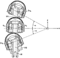
これら及び他の特徴は図面に示す例から明らかになる。図1から分かるように、シェーバー1は、シェーバーを保持するためのハンドル2を形成するシェーバーハウジングを有していてもよい。ハンドルは、異なる形状を有していてもよく、例えば、大まかに言うと、シェーバーを人間工学的に掴むこと又は保持することを可能にする実質的に円筒形状又は箱形又は骨形状である。このようなシェーバーハンドル2は、このようなハンドルの細長い形状(図1を参照)に起因して長手方向軸20を有している。
These and other features will be apparent from the examples shown in the drawings. As can be seen from FIG. 1, the shaver 1 may have a shaver housing that forms a
ハンドル2の一端において、シェーバーヘッド3は、ハンドル2に取り付けられ、シェーバーヘッド3は、旋回軸7を中心に、かつ傾動軸211を中心に回転可能に支持され得る。旋回軸7と傾動軸211は、互いに対して実質的に垂直に、かつ前述の長手方向のハンドル軸20に対して垂直に延在し得る。
At one end of the
シェーバーヘッド3の主軸40を考慮する場合、旋回軸7はこのような主軸40と平行に延在していてもよく、傾動軸211はこのような主軸40に対して横方向に延在していてもよい。このような主軸40は、シェーバーヘッド3の大きい側面55及び57と平行に、及び/又は細長いカッター要素4の長手方向軸と平行に、及び/又は長手方向のハンドル軸20に実質的に垂直に延在すると考えられ得る。図1から分かるように、シェーバーヘッド3は、大まかに言うと、ハンドル2から離れて向き合う機能性表面56の対向する側に配置された一対の大きい側面55及び57を有する実質的に矩形の箱状の形状を有してもよい。シェーバーヘッド3は、前述の大きい側面55及び57並びに機能性表面56と隣接する2つの小さい側面58及び59を更に有する。
When considering the
シェーバーヘッド3は、カッター要素4をそれぞれ有する一対の細長いカッターユニット100を含んでもよく、それは、前述の主軸40に対して平行に延在し得る往復運動軸8に沿って往復運動する様式で駆動することができる。またシェーバーヘッドは、1つのみ又は3つ又は4つ以上のこのようなカッター要素を含むこともまた実行可能である。カッター要素4は、カッター要素4を覆うせん断フォイル5と協働し、せん断フォイル5の下で往復運動し得る。このようなカッター要素4に加えて、シェーバーヘッド3は、2つの前述のカッター要素4の間に位置され得るロングヘアーカッター及び/又は冷却要素及び/又は潤滑要素などの他の機能的要素を更に含んでもよい。カッター往復運動軸8は、傾動軸211に対して横方向に延在する。
The shaver head 3 may include a pair of
カッター要素4は、シェーバーヘッド3に対して、又はより詳細には、シェーバーヘッドフレーム6に対して移動可能に支持されてもよく、そのため一方で、カッター要素4は、旋回軸7及び傾動軸211を中心にシェーバーヘッド3と一緒に旋回し、傾動してもよく、一方で、カッター要素4は、シェーバーヘッドフレーム6に対して切断軸又は往復運動軸8に沿って振動してもよい。その往復運動軸8は、細長いカッター要素4の長手方向軸に対して平行に延在し得る。これらの自由度に加えて、カッター要素4は、追加的な軸に沿って及び/又はそれを中心にシェーバーヘッドフレーム6に対して運動可能であってもよい。例えば、カッター要素4は、シェーバーヘッド3内に潜り込んでもよく、すなわち、シェーバーヘッド3がそれと整列した位置にあるときに長手方向のハンドル軸20に対して実質的に平行な軸に沿って変位する。
The
図2〜図7から分かるように、各カッター要素4は、シェーバーハウジング2からシェーバーヘッド3内にカッター要素4まで延在する細長い駆動伝達器9によって、振動様式で駆動され得る。このような細長い駆動伝達器9は、シェーバーハウジング又はハンドル2の内部からハンドル2の外部に延在する剛直なシャフト90を含んでもよく、それは、シェーバーヘッド3内へとシェーバーハウジングの外部シェルを通じる手段であり、駆動ユニットは、シェーバーハウジング内に収容され、シャフト90を振動様式で回転させるモータ93を含んでもよい。このようなモータ93は、例えば、モータシャフトの回転をシャフト90の回転振動に変換するクランク機構を介して、シャフト90に好適に接続された回転電気モータであってよい。
As can be seen from FIGS. 2 to 7, each
シャフト90は、その長手方向軸を有して、特に、長手方向のシェーバーハウジング軸20に対して実質的に平行であり、又はそれに対してわずかに傾斜されるシェーバーハウジング2に対する固定的な配向で保持される。
The
図2は1つの駆動ピン91しか示していないが、2つのカッター要素4がある場合には2つの駆動ピンがあってもよく、このような細長い駆動ピン91は互いに平行に延在しており(図7を参照)、又は3つ以上のカッター要素4がある場合には3つ以上の駆動ピン91があってもよいことは図2から明らかである。
FIG. 2 shows only one
駆動ピン91は、前述のシャフト90によってそれぞれ駆動されて、細長いカッター要素4の長手方向の延長に実質的に平行な方向において、シェーバーヘッド3に対して一軸的に振動する(図4及び図5を参照)。より詳細には、軸90及びクランクアーム92の回転振動に起因して、駆動ピン91は、環状経路に沿って振動を行う。しかし、クランクアーム92がカッター要素4の振動軸と実質的に垂直な方向に延在しているため、クランクアーム92が、シャフト90及びクランクアーム92の中立位置又は中間位置から前後逆方向に回転振動することを少なくとも考慮すると、駆動ピン91が沿って振動する環状経路のセグメントは振動軸8に対して接線方向に配向される。回転振動の振幅が制限されるので、環状経路のセグメントは、振動軸8に対してほぼ平行並びに/又は振動軸8に対してほぼ直線状及び平行であると考えられ得る。
The drive pins 91 are each driven by the
シャフト90及び駆動ピン91を含む全体的な駆動伝達器9は、細長い駆動伝達器9のその駆動ピン91に関する突出端がカッター要素4に設けられた内部空間内に延在するようにハンドル2からカッター要素4内に延在し得る。
The
シャフト90、クランク要素92及び駆動ピン91を含む全体的な駆動伝達器9は回転可能であるが、それ以外は剛直に支持される剛性構造体を形成し、その結果、各駆動ピン91によって画定された長手方向軸13は、ハンドル2に対して固定的な配向に延在する。このような長手方向軸13は、ハンドルの長手方向軸20に対して実質的に平行又は鋭角でそれに対して傾斜していてもよい。
The
図2〜図5から分かるように、細長い駆動伝達器9の駆動ピン91は、カッター要素4と係合するボール継手部品を形成するブロック状又はスリーブ状コネクタ15を含み得る枢動継手10によって、カッター要素4に結合されている。ボール継手部品は、硬質プラスチック素子であってもよく、又は金属等のその他の抵抗性軸受材料で作られてもよい。コネクタ15は、細長い駆動伝達器9の端部をカッター要素4に直接接続し、細長い駆動伝達器9の端部は、カッター要素4に装着されたコネクタ部品15に受けられ得る。
As can be seen from FIGS. 2-5, the
図3から分かるように、コネクタ15は、細長い駆動伝達器9の駆動ピン91上でその長手方向軸線に沿ってコネクタ15が摺動することを可能にする孔として形成され得る、伝達器凹部17を有し得る。
As can be seen from FIG. 3, the
コネクタ15は、球状のキャップ又は半球又はほぼ完全な球体を形成し得る球状支持面22を備えることができる。カッター要素4には、細長い駆動伝達器9の駆動ピン91に装着されたボール継手部品の球状支持面22と協働及び係合する、対応する球状又はドーム状又は円筒状又は丸みのある支持面23が提供される。図4及び図5から分かるように、コネクタ15の球状支持面22には、凸面が形成されてもよく、又はそれは外側面として形成されてもよく、一方で、カッター要素4の支持面23には、凹面が形成されてもよく、又はそれは内側支持面として形成されてもよい。基本的には、コネクタの支持面22を凹面とし、カッター要素の支持面23を凸面とした逆の構成が可能である。カッター要素4及び細長い駆動伝達器9の駆動ピン91の寸法により、駆動伝達器側に凸状支持面22を有し、カッター要素側に凹状支持面を有する前述の構成は、より省スペースでコンパクトな構成を可能にする。
The
カッター要素4の支持面23は、カッター要素の本体壁によって直接的に形成され得る。代替として、カッター要素は、カッター要素4に固定的に取り付けられ、支持面23を形成する支持体又は軸受インサート又はアタッチメントを含むことができる。
The
球状及び/又はドーム状又は丸みのある支持面22及び23は、互いにくっつき合って嵌合し、その結果、コネクタ15は、少なくともカッター要素4が振動様式で沿って駆動するカッター振動軸8の方向に、遊びなくカッター要素4に保持される。より詳細には、コネクタ15は、球状又は丸みのある支持面22及び23に起因して、互いに垂直及び細長い駆動伝達器9の駆動ピン91の長手方向軸13に対して横方向に延在する枢動軸11及び12を中心にカッター要素4に対して枢動し得る。枢動軸11、12は、コネクタ15のヘッドの中央部分を通じて、より具体的には、球状及び/又はドーム状及び/又は丸みのある支持面22及び23の曲率中心を通じて実質的に延在する(図2、図4及び図14を参照)。
Spherical and / or dome-shaped or rounded support surfaces 22 and 23 fit together so that the
細長い駆動伝達器9は、前述のカッター振動軸8と実質的に平行な方向において、コネクタ15の伝達器凹部17内に剛直に変位不能に受けられているので、そのため細長い駆動伝達器9の駆動ピン91は、カッター要素4に対して正確な位置に保持される。換言すれば、カッター振動軸8に沿ったカッター要素4の細長い駆動伝達器9に対する相対運動は不可能であり、更にカッター要素4は、遊びなくカッター振動軸8のその方向の細長い駆動伝達器9のいくつかの移動に瞬間的に従うこともない。
Since the
振動軸8以外のその他の方向における、相対運動は実行可能である。具体的には、枢動継手10は、カッター要素4が駆動ピン91に沿って潜り込み得るように、長手方向軸13の方向113の駆動ピン91に対するカッター要素4の相対運動を可能にするように構成される。このような実質的に駆動ピンの長手方向軸13に沿った変位は、コネクタ15の駆動ピン91に対する摺動可能な接続により達成され得る。加えて又は代替的に、コネクタ15のヘッドセクションは、カッター要素4の凹部に摺動可能に受けられ得、そのことはコネクタ15のボール状又は球面状支持面22を受ける一種の円筒状部分で支持面23を形成することにより達成することができる。その結果、コネクタ15は、環状断面又は楕円形断面を有し得るこのような円筒状部分内に摺動して、振動軸8に垂直な方向かつ駆動ピン91の長手方向軸に対して横方向の追加的な相対変位を可能にし得る。しかし、前述したように、コネクタ15は、駆動ピン91に沿って摺動して、カッター要素4のドーム状支持面23と係合しているコネクタ15の球面状支持面22を用いてカッター要素4が駆動ピン91に対して潜り込むことを可能にし得、ばね装置又は付勢装置は、コネクタ15の球面状支持面をカッター要素4のドーム状支持面の方に向かってそれと係合するように促すために提供され得る。
Relative motion is feasible in directions other than the
カッター振動軸8に対して横方向及び駆動ピン91の長手方向軸13に対して横方向の方向111では、細長い駆動伝達器9に関して遊び及び変位が可能であり、細長い駆動伝達器9はカッター要素4に対して移動可能である。前述の横方向111の細長い駆動伝達器9に対するカッター要素4のこのような自由度は、カッター要素4に形成された伝達器凹部17の細長いスロット状輪郭によって達成され得、このような輪郭は、コネクタ15の球状支持面22に係合するドーム状のルーフセクションを有し得る。図14に示すように、スロット状の伝達器凹部17の長さLは、細長い駆動伝達器9の直径又は厚さよりもかなり大きい。例えば、スロット状の伝達器凹部17の長さLは、細長い駆動伝達器9の厚さの少なくとも150%であってもよく、細長い駆動伝達器9の厚さの200%又は300%以上のスロット長を有することも可能である。
In the lateral direction with respect to the
図14から分かるように、伝達器凹部17の細長いスロット状の孔の幅Wは、駆動伝達器9の厚さ、より詳細には駆動ピン91上のコネクタ15の厚さにおおよそ正確に対応し、そのため細長い駆動伝達器9は、このスロットの長さ方向に沿ってのみ移動し得る。
As can be seen from FIG. 14, the width W of the elongated slot-shaped hole in the
カッター要素4に対する駆動ピン91の横方向の変位は、3つの異なる角度位置におけるカッター要素4を示す図15によって更に示される。それらの位置は、旋回軸7を中心にハンドル2に対してシェーバーヘッド3を旋回させたときに到達する。図15に示すように、旋回角αは、例えば、+/−5°又は+/−10°又は+/−15°であり得、あるいは+/−5°〜+/−15°の範囲であり得る。例えば、旋回軸7が一対のカッターユニット100の間に位置付けられる事例であり得るような枢動継手10から離間した旋回軸7の位置によって、カッター要素4は、駆動ピンの長手方向軸13に対して横及び旋回軸7に対して横の方向111で枢動継手10に対して変位する。図15において、基準cxは、スロット状の伝達器凹部17とその長さLとがなすこのような横方向111の隙間を示す。このような隙間cxは、+/−0.7mm〜1mm又は+/−0.7mm〜+/−1.2mmの範囲であってもよく、したがって合計で1mm〜2.4mmの範囲であってもよい。図15に示すような旋回運動によって生じる横方向の変位に加えて又はその代替として、方向111の同様の横方向の運動がまた、図7から明らかであるように、正確には線形の振動を実行しないがシャフト90を中心とした回転振動を実行する、駆動ピン91の往復運動の環状経路により生じ得る。
The lateral displacement of the
図4の矢印113で示すように、駆動ピン91とカッター要素4とを接続する接続部又は枢動継手10は、カッター要素4が、駆動ピン91に対してその長手方向軸に沿って潜り込み得、駆動ピン91に対してその長手方向軸13を中心に回転し得、更に矢印111で示すように、駆動ピン91及び振動軸8に対して横方向に摺動し得るように構成される。一方では、接続部又は枢動継手10は、遊びがなく振動軸8の方向の相対運動がないように構成される。
As shown by the
図8及び図9から分かるように、シェーバーヘッド3は、平行軸を中心に枢動し得る一対のリンクアーム31及び32を備え得る四継手連結機構33を含み得る、支持構造体30によってハンドル2上に支持される。このようなリンクアーム31及び32は、図13に示すようなコ字状断面を含む棒状又はフレーム状構造を有し得る。
As can be seen from FIGS. 8 and 9, the shaver head 3 may include a four-
リンクアーム31及び32は、直立構成に配置される。ここで、シェーバーヘッド3に接続されたこれらのリンクアーム31及び32の端部は、ハンドル2又はこのようなハンドル2に接続されたベース部45に接続されたこれらのリンクアーム31及び32の対向する端部よりもハンドル2から更に離れている。別の言い方をすると、ハンドル2の上方でシェーバーヘッド3を有して直立位置にあるシェーバー1を考慮すると、リンクアーム31及び32の上端部がシェーバーヘッド部に接続され、一方で、リンクアーム31及び32の下端部がハンドル2又はそれに装着されたベース部に接続される。
The
シェーバーヘッド3の中立又は非傾斜位置において、シェーバーヘッド3の主軸40は、長手方向ハンドル軸20に対して実質的に垂直に延在し、リンクアーム31及び32は、長手方向ハンドル軸20を含む中心面に対して対称に配置され得る(図8(a)を参照)。より詳細には、リンクアーム31及び32は、鋭角でこのような中心面に対して傾斜され得る。
In the neutral or non-tilted position of the shaver head 3, the
図8及び図9から分かるように、リンクアーム31及び32がハンドル2又はベース部45に枢動可能に接続されている場合のハンドル継手31b及び32bは、リンクアーム31及び32がシェーバーヘッド部に枢動可能に接続されている場合のヘッド継手31aと32aとの間の距離よりも大きい距離L1で互いに間隔をおいて配置される。距離L1と距離L2との比は、上記で説明したような所望の運動学を達成するために、リンクアーム31及び32の長さに応じて変化及び/又は適合されてもよい。
As can be seen from FIGS. 8 and 9, in the handle joints 31b and 32b when the
図8から分かるように、シェーバーヘッドフレーム6は、リンクアーム31及び32にそのヘッド継手31a及び32aで接続され得、そのことは傾動軸211と平行な枢動軸を画定する。結果として、シェーバーヘッドフレーム6は、傾動軸211を中心としてハンドル2に対して傾動し得る。
As can be seen from FIG. 8, the
更に、シェーバーヘッドフレーム6は、カッター支持フレーム46等の別のシェーバーヘッド部を枢動可能に支持して、このようなカッター支持フレーム46がシェーバーヘッドフレーム6とカッター支持フレーム46との間のこのような枢動軸受によって画定された旋回軸7を中心に旋回することを可能にし得る。このような枢動軸受は、孔又は凹部内に受けられるシャフト又は無精ひげを含んでもよく、旋回軸7は、シェーバーヘッドフレーム6に対して固定されてもよい。
Further, the
前述のカッター要素4は、カッター支持フレーム46で支持されてもよく、カッター要素4は、カッター支持フレーム46に対する往復運動軸8に沿った前述の往復駆動運動を実行することを許容され得る。加えて、カッター要素4は、ハンドル2の方へこのようなカッター支持フレーム46に対して潜り込むことができる。
The
四継手連結機構33の前述の直立構成により、シェーバーヘッド3は、その傾動の後、ハンドル2から離れるように、及び/又はベース部45から離れるようにシェーバーヘッド3を促す付勢手段70によって、中立又は非傾斜位置に戻り得る。図7から分かるように、このような付勢手段70は、ハンドル2から離れるようにカッターユニットを付勢するばね装置を含み得、このようなばねは、往復運動様式でカッター要素4を駆動するために、前述のカッターユニット100と駆動トレイン要素との間に位置付けられ得る。したがって、付勢手段70は、リンクアーム31及び32を付勢してシェーバーヘッド3をその中立、非傾斜位置にすること、並びにカッターユニット4が潜り込む及び/又は浮動するのを可能にすること含む、二重機能又は多機能を発揮することができる。
Due to the above-mentioned upright configuration of the four-
シェーバーヘッド構造体に対するカッター要素4のこのような潜り込みに対して追加的に、又は代替的に、カッター要素4を含む全体的なシェーバーヘッド3の潜り込みも実行可能である。例えば、前述のリンクアーム31及び32は、ハンドル2に直接接続する必要がないが、これらは、ハンドル2上に移動可能に支持されて、基本的にハンドル2の長手方向軸20に沿って移動し得るベース部45に連結されてもよい。別の言い方をすると、リンクアーム31及び32、したがって全体的なシェーバーヘッド3を枢動可能に支持するベース部45は、ハンドル2の方へ潜り込み得、付勢装置又はばね装置は、ハンドル2とベース部45との間に提供されて、ハンドル2から離れるように及び/又はシェーバーヘッド3の方にベース部45を付勢する又は促すことができ、その結果、シェーバーヘッド3は、付勢又はばね力に対して潜り込み得る。代替的に、しかし、このようなベース部45はまた、ハンドル2に剛直に装着されてもよい。
Additional or alternative to such diving of the
図8及び図9から分かるように、旋回支持構造体は、傾動運動を可能にする四継手連結機構33がハンドル2と旋回支持構造体34との間に配置され場合に、傾動軸211を中心とした傾動運動を実行することができる。しかし、図10に示すように、傾動運動を許容する四継手連結機構33が旋回運動を実行するように、このような順序や構造を反転させてもよい。より詳細には、ベース部45は、ハンドル2に枢動可能に支持されて、ハンドル2に対して旋回軸7を中心に旋回することができてもよい。四継手連結機構33のリンクアーム31及び32は、それらのハンドル継手31b及び32bを用いてこのような旋回ベース部45に接続されてもよい(図10を参照)。
As can be seen from FIGS. 8 and 9, the swivel support structure is centered on the
また、図11から分かるように、枢動軸受構造体で置換された四点連結機構33を有することも可能である。これにより、旋回及び傾動の両方を各枢動軸受構造体により達成することができる。
Further, as can be seen from FIG. 11, it is also possible to have the four-
図8及び図9に示すように、旋回軸7は、カッター要素4を通じて又はそれに非常に近接して延在してもよい。この旋回軸7は、一対のカッター要素が設けられているときにカッター要素4の間に延在していてもよい。例えば、旋回軸7は、シェーバーヘッド3の上半分、すなわちハンドル2から更に離れたシェーバーヘッド3の半分に延在してもよく、又はシェーバーヘッド3の最上部の四半分に、又はシェーバーヘッド3の上部分を通じて延在してもよく、ここにブロック状のカッター要素4が収容される。
As shown in FIGS. 8 and 9, the
四継手連結機構33によって画定された傾動軸211は、旋回軸7に近接して配置されてもよい。より具体的には、傾動軸211は、四継手連結機構33並びにリンクアーム31及び32の移動によって移動され得る。図8から分かるように、一方のリンクアーム31のヘッド継手31a及びハンドル継手31bを通る一方の仮想直線と、他方のリンクアーム32のヘッド継手32a及びハンドル継手32bを通る他方の仮想直線との交点は、傾動軸211に対応する瞬間的な回転の中心61を画定し、その瞬間的な回転の中心61は、経路又はポールホード60に沿って移動し得る。
(4) The tilting
リンクアーム31及び32、特にその長さ並びにそのヘッド継手及びハンドル継手の位置決めは、瞬間的な回転の中心61に関する傾動軸211が沿って移動し得るポールホード60が、シェーバーの動作中のハンドルに対するシェーバーヘッドの傾動の制限された動作範囲を考慮して機能性表面56の方への凸状の輪郭を有するように構成され得る。このようなポールホード60の凸状湾曲は、シェーバーヘッド3が傾動軸211を中心に傾動する場合であっても旋回軸7に近接して瞬間的な回転の中心61を保つやや浅い輪郭を有し得る。
The positioning of the
図8から分かるように、リンクアーム31及び32は、傾動軸211に関するポールホード60がシェーバーヘッド3内に全体的に延在し得るように構成され得、このようなポールホード60の主要部は、シェーバーヘッド3の上半分、すなわちハンドル2から更に離れたシェーバーヘッド3の半分に延在し得る。例えば、図8aに示すような中立又は非傾斜のシェーバーヘッド位置のポールホード60の中点を考慮した場合、少なくとも左に3分の1の長さのポールホード60と右に3分の1の長さのポールホード60は、シェーバーヘッド3の上半分に延在し得る。
As can be seen from FIG. 8, the
一態様によれば、リンクアーム31及び32の構成は、傾動軸211を中心にシェーバーヘッド3を傾動したときにカッター要素4が軌道62に沿って移動する領域内でシェーバーヘッド3の仮想中心点41を有するように選ばれてもよく、軌道61は、ハンドル2に向かって互いに分岐する2つの軌道枝を含むピッチルーフ状構成を有してもよい。前述の中点41は、非傾斜位置での長手方向ハンドル軸20とシェーバーヘッド3の旋回軸7との交点付近の領域における、リンクアーム31及び32のヘッド継手31a及び32aに取り付けられたシェーバーヘッド部の定点とみなされ得る。シェーバーヘッド3の傾動中のこの中点41の流れに関して、中点41は軌道62に沿って移動し、その輪郭は、四点連結機構33の構成によって画定される。図8に示すように、軌道62は、シェーバーヘッド3の機能性表面側から軌道62を見たときに凸状輪郭を有し得、軌道62は、中心ピークを有してもよく、2つの軌道枝がそれからハンドル2に向かって下がっている。このような凸状の軌道に起因して、中点41がまた、シェーバーヘッド3が傾動した場合にわずかに潜り込む。
According to one aspect, the configuration of the
輪郭適用の良好な制御及びシェーバーの改善された操作性のために、シェーバーヘッド3のその傾動についての運動学が提供され得る。具体的には、シェーバーヘッド3は、シェーバーヘッド3がその中立位置若しくは非傾斜位置にあるとき又はわずかに傾斜しているときに傾動に対する高められた安定性を示し、一方で、シェーバーヘッドは、すでにある程度傾斜している場合にはより容易に更に傾斜する。別の言い方をすると、傾斜角を大きくすることに伴ってシェーバーヘッドの傾く意向が増大する。 Due to the good control of contour application and the improved maneuverability of the shaver, kinematics about its tilt of the shaver head 3 may be provided. Specifically, the shaver head 3 exhibits increased stability against tilt when the shaver head 3 is in its neutral or non-tilted position or when it is slightly tilted, while the shaver head 3 If it is already tilted to some extent, it will be more easily tilted. In other words, the tendency of the shaver head to tilt increases as the tilt angle increases.
このことは、図12から見ることができ、シェーバーヘッド3の端部側から離れて移動する傾動軸211を画定する瞬間的な回転の中心により達成され、又は少なくとも支持され得、傾動時にその端部側においてシェーバーヘッド3がハンドルに向かって潜り込む。例えば、図12は、時計回りの傾動によって潜り込むシェーバーヘッド3の右手側を示す。傾動軸211、より詳細にはポールホード60に沿ってシェーバーヘッド3の左端側に向かって移動するための瞬間的な回転の中心を生じる四継手連結機構33の構成に起因して、接触力のレバーアームはシェーバーヘッド3を更に傾動するように付勢し、傾動角の増大に伴ってレバーアーム80は大きくなる。更に右側へシェーバーヘッド3が傾動すると、瞬間的な回転の中心は更に左側に向かって移動し、このことは機能性表面56の部分を増加させ、それに基づいて接触圧力がレバーアームを得て、シェーバーヘッド3を更に傾動する(図12の部分図(b)を参照)。
This can be seen from FIG. 12, which can be achieved or at least supported by a momentary center of rotation defining a
本明細書にて開示した寸法及び値は、記載された正確な数値に厳密に限定されるものと理解されるべきではない。むしろ、特に指示がない限り、このような各寸法は、記載された値及びその値の周辺の機能的に同等の範囲の両方を意味することが意図される。例えば「40mm」として開示される寸法は、「約40mm」を意味するものとする。 The dimensions and values disclosed herein should not be understood to be strictly limited to the exact numerical values given. Rather, unless otherwise indicated, each such dimension is intended to mean both the stated value and the functionally equivalent range around that value. For example, the dimension disclosed as "40 mm" shall mean "about 40 mm".
Claims (17)
−前記カッター要素(4)のカッター要素本体と一体的に形成され、若しくはそれと剛直に固定され、又は
−カッター要素本体に接続され、前記シェーバーヘッド(3)のせん断フォイル(5)に対して前記カッター要素本体を弾性的に付勢するカッター要素ばね(28)上に提供されている、請求項1〜8のいずれか一項に記載の電気シェーバー。 The pivot joint support surface (23) of the cutter element (4) for supporting the pivot joint (10) is
-Formed integrally with or rigidly fixed to the cutter element body of the cutter element (4), or-connected to the cutter element body and described above with respect to the shear foil (5) of the shaver head (3). The electric shaver according to any one of claims 1 to 8, which is provided on a cutter element spring (28) that elastically urges the cutter element body.
−前記カッター要素(4)を通って、かつ/又はそれに隣接して延在し、前記ハンドル(2)に対する前記シェーバーヘッド(3)の回転の動作範囲を考慮したときに、剃られる皮膚と接触する前記シェーバーヘッド(3)の機能性側(56)に向かって凸状である湾曲した形状を有する、経路(60)に沿って移動する瞬間的な回転の中心を画定するように構成されている、請求項11〜14のいずれか一項に記載の電気シェーバー。 The link arm (31, 32)
-Contact with the skin to be shaved when extending through and / or adjacent to the cutter element (4) and considering the range of motion of rotation of the shaver head (3) with respect to the handle (2). The shaver head (3) has a curved shape that is convex toward the functional side (56), and is configured to define the center of momentary rotation moving along the path (60). The electric shaver according to any one of claims 11 to 14.
Applications Claiming Priority (3)
| Application Number | Priority Date | Filing Date | Title |
|---|---|---|---|
| EP16191099.7A EP3300843B1 (en) | 2016-09-28 | 2016-09-28 | Electric shaver |
| EP16191099.7 | 2016-09-28 | ||
| PCT/IB2017/055853 WO2018060852A1 (en) | 2016-09-28 | 2017-09-26 | Electric shaver |
Publications (2)
| Publication Number | Publication Date |
|---|---|
| JP2019534068A JP2019534068A (en) | 2019-11-28 |
| JP6970193B2 true JP6970193B2 (en) | 2021-11-24 |
Family
ID=57018068
Family Applications (1)
| Application Number | Title | Priority Date | Filing Date |
|---|---|---|---|
| JP2019515923A Active JP6970193B2 (en) | 2016-09-28 | 2017-09-26 | Electric shaver |
Country Status (5)
| Country | Link |
|---|---|
| US (1) | US10596714B2 (en) |
| EP (1) | EP3300843B1 (en) |
| JP (1) | JP6970193B2 (en) |
| CN (1) | CN109789581B (en) |
| WO (1) | WO2018060852A1 (en) |
Families Citing this family (5)
| Publication number | Priority date | Publication date | Assignee | Title |
|---|---|---|---|---|
| EP3300861B1 (en) | 2016-09-28 | 2019-07-03 | Braun GmbH | Electrically driven device |
| EP3300843B1 (en) * | 2016-09-28 | 2020-04-15 | Braun GmbH | Electric shaver |
| JP7022004B2 (en) * | 2018-04-27 | 2022-02-17 | マクセル株式会社 | Electric shaver |
| US20230064384A1 (en) * | 2021-08-27 | 2023-03-02 | Wahl Clipper Corporation | Shaver |
| JP1739358S (en) * | 2022-07-01 | 2023-03-20 |
Family Cites Families (22)
| Publication number | Priority date | Publication date | Assignee | Title |
|---|---|---|---|---|
| FR1158440A (en) | 1956-10-23 | 1958-06-13 | Electric razor improvements | |
| FR1391957A (en) | 1964-01-30 | 1965-03-12 | Thomson Houston Comp Francaise | Electric razor improvements |
| US3748371A (en) | 1972-05-18 | 1973-07-24 | Ericsson Telefon Ab L M | Insulated cable with wire for slitting a protective sheath |
| US4700476A (en) * | 1984-11-02 | 1987-10-20 | Remington Products, Inc. | Shaver for a medical treatment preparation procedure |
| DE4244164C2 (en) | 1992-12-24 | 1995-09-07 | Braun Ag | Dry shaver with a pivoting long hair trimmer |
| GB9614159D0 (en) * | 1996-07-05 | 1996-09-04 | Gillette Co | Dry shaving apparatus |
| DE19736776C2 (en) * | 1997-08-23 | 1999-06-02 | Braun Gmbh | Dry shaver |
| AT409604B (en) | 2000-01-14 | 2002-09-25 | Payer Lux Elektroprod | Electric shaver |
| EP1444073B1 (en) * | 2001-11-15 | 2005-09-07 | Matsushita Electric Works, Ltd. | Dry shaver with a cradle shaving head |
| BE1016776A3 (en) * | 2005-09-21 | 2007-06-05 | Bvba Versus Omega | IMPROVED FOLDING AID FOR COVERS OF LARGE VEHICLES OR THE LIKE. |
| DE102006010323A1 (en) | 2006-03-07 | 2007-09-13 | Braun Gmbh | Dry shaver with swiveling shaving head |
| DE102006030947A1 (en) | 2006-07-05 | 2008-01-10 | Braun Gmbh | Electric dry shaver |
| DE102008031132A1 (en) * | 2008-07-01 | 2010-01-07 | Braun Gmbh | Small electrical appliance for removing hair |
| JP5467628B2 (en) * | 2008-12-25 | 2014-04-09 | 日立マクセル株式会社 | Electric razor |
| JP4955711B2 (en) * | 2009-01-15 | 2012-06-20 | パナソニック株式会社 | Electric razor |
| CA2763243C (en) | 2009-05-28 | 2016-10-25 | Koninklijke Philips Electronics N.V. | Pivoting arrangement |
| JP6242713B2 (en) * | 2014-02-26 | 2017-12-06 | マクセルホールディングス株式会社 | Electric razor |
| JP6395303B2 (en) | 2014-10-15 | 2018-09-26 | マクセルホールディングス株式会社 | Electric razor |
| EP3300854B1 (en) * | 2016-09-28 | 2020-06-10 | Braun GmbH | Electric shaver |
| EP3300843B1 (en) * | 2016-09-28 | 2020-04-15 | Braun GmbH | Electric shaver |
| EP3300848B1 (en) * | 2016-09-28 | 2019-10-23 | Braun GmbH | Electric shaver |
| EP3305485B1 (en) * | 2016-09-28 | 2019-07-03 | Braun GmbH | Electric shaver |
-
2016
- 2016-09-28 EP EP16191099.7A patent/EP3300843B1/en active Active
-
2017
- 2017-09-25 US US15/714,991 patent/US10596714B2/en active Active
- 2017-09-26 JP JP2019515923A patent/JP6970193B2/en active Active
- 2017-09-26 CN CN201780059920.2A patent/CN109789581B/en active Active
- 2017-09-26 WO PCT/IB2017/055853 patent/WO2018060852A1/en active Application Filing
Also Published As
| Publication number | Publication date |
|---|---|
| EP3300843B1 (en) | 2020-04-15 |
| WO2018060852A1 (en) | 2018-04-05 |
| CN109789581A (en) | 2019-05-21 |
| CN109789581B (en) | 2021-10-29 |
| US20180085938A1 (en) | 2018-03-29 |
| US10596714B2 (en) | 2020-03-24 |
| EP3300843A1 (en) | 2018-04-04 |
| JP2019534068A (en) | 2019-11-28 |
Similar Documents
| Publication | Publication Date | Title |
|---|---|---|
| JP6970193B2 (en) | Electric shaver | |
| JP6845311B2 (en) | Electric shaver | |
| JP6770186B2 (en) | Electric shaver | |
| JP7004702B2 (en) | Electric shaver | |
| JP7032389B2 (en) | Electric shaver | |
| JP6898438B2 (en) | Razor coupling and electric razor with coupling | |
| GB2458316A (en) | Manual shaving razor with head rotatably mounted on handle | |
| KR100660979B1 (en) | Razor of head moving | |
| CN109803800B (en) | Electric drive device | |
| GB2463035A (en) | Manual shaving razor with damping elastic elements |
Legal Events
| Date | Code | Title | Description |
|---|---|---|---|
| A621 | Written request for application examination |
Free format text: JAPANESE INTERMEDIATE CODE: A621 Effective date: 20190322 |
|
| A131 | Notification of reasons for refusal |
Free format text: JAPANESE INTERMEDIATE CODE: A131 Effective date: 20200616 |
|
| A601 | Written request for extension of time |
Free format text: JAPANESE INTERMEDIATE CODE: A601 Effective date: 20200916 |
|
| A521 | Written amendment |
Free format text: JAPANESE INTERMEDIATE CODE: A523 Effective date: 20201116 |
|
| A131 | Notification of reasons for refusal |
Free format text: JAPANESE INTERMEDIATE CODE: A131 Effective date: 20210202 |
|
| A601 | Written request for extension of time |
Free format text: JAPANESE INTERMEDIATE CODE: A601 Effective date: 20210506 |
|
| A521 | Written amendment |
Free format text: JAPANESE INTERMEDIATE CODE: A523 Effective date: 20210618 |
|
| TRDD | Decision of grant or rejection written | ||
| A01 | Written decision to grant a patent or to grant a registration (utility model) |
Free format text: JAPANESE INTERMEDIATE CODE: A01 Effective date: 20210928 |
|
| A61 | First payment of annual fees (during grant procedure) |
Free format text: JAPANESE INTERMEDIATE CODE: A61 Effective date: 20211028 |
|
| R150 | Certificate of patent or registration of utility model |
Ref document number: 6970193 Country of ref document: JP Free format text: JAPANESE INTERMEDIATE CODE: R150 |