JP6970167B2 - Systems and methods for determining at least one parameter associated with mandrel angular movement - Google Patents
Systems and methods for determining at least one parameter associated with mandrel angular movement Download PDFInfo
- Publication number
- JP6970167B2 JP6970167B2 JP2019220112A JP2019220112A JP6970167B2 JP 6970167 B2 JP6970167 B2 JP 6970167B2 JP 2019220112 A JP2019220112 A JP 2019220112A JP 2019220112 A JP2019220112 A JP 2019220112A JP 6970167 B2 JP6970167 B2 JP 6970167B2
- Authority
- JP
- Japan
- Prior art keywords
- reflector
- mandrel
- determination system
- rotary reflector
- detector
- Prior art date
- Legal status (The legal status is an assumption and is not a legal conclusion. Google has not performed a legal analysis and makes no representation as to the accuracy of the status listed.)
- Active
Links
- 238000000034 method Methods 0.000 title claims description 26
- 230000033001 locomotion Effects 0.000 title claims description 20
- 230000006870 function Effects 0.000 claims description 14
- 238000004590 computer program Methods 0.000 claims description 7
- 239000002184 metal Substances 0.000 claims description 5
- 229910052751 metal Inorganic materials 0.000 claims description 5
- 238000004804 winding Methods 0.000 claims description 5
- 230000001419 dependent effect Effects 0.000 claims description 4
- 239000010453 quartz Substances 0.000 claims description 4
- VYPSYNLAJGMNEJ-UHFFFAOYSA-N silicon dioxide Inorganic materials O=[Si]=O VYPSYNLAJGMNEJ-UHFFFAOYSA-N 0.000 claims description 4
- 230000010363 phase shift Effects 0.000 description 8
- 230000003287 optical effect Effects 0.000 description 5
- 238000005286 illumination Methods 0.000 description 2
- 230000005355 Hall effect Effects 0.000 description 1
- 230000005540 biological transmission Effects 0.000 description 1
- 238000004364 calculation method Methods 0.000 description 1
- 238000001514 detection method Methods 0.000 description 1
- 238000005265 energy consumption Methods 0.000 description 1
- PCHJSUWPFVWCPO-UHFFFAOYSA-N gold Chemical compound [Au] PCHJSUWPFVWCPO-UHFFFAOYSA-N 0.000 description 1
- 239000010931 gold Substances 0.000 description 1
- 229910052737 gold Inorganic materials 0.000 description 1
- 230000001681 protective effect Effects 0.000 description 1
- 238000000926 separation method Methods 0.000 description 1
- 238000007740 vapor deposition Methods 0.000 description 1
Images


Classifications
-
- G—PHYSICS
- G04—HOROLOGY
- G04D—APPARATUS OR TOOLS SPECIALLY DESIGNED FOR MAKING OR MAINTAINING CLOCKS OR WATCHES
- G04D7/00—Measuring, counting, calibrating, testing or regulating apparatus
- G04D7/002—Electrical measuring and testing apparatus
-
- G—PHYSICS
- G04—HOROLOGY
- G04B—MECHANICALLY-DRIVEN CLOCKS OR WATCHES; MECHANICAL PARTS OF CLOCKS OR WATCHES IN GENERAL; TIME PIECES USING THE POSITION OF THE SUN, MOON OR STARS
- G04B9/00—Supervision of the state of winding, e.g. indicating the amount of winding
- G04B9/005—Supervision of the state of winding, e.g. indicating the amount of winding by optical indication of the amount of winding
-
- G—PHYSICS
- G04—HOROLOGY
- G04C—ELECTROMECHANICAL CLOCKS OR WATCHES
- G04C3/00—Electromechanical clocks or watches independent of other time-pieces and in which the movement is maintained by electric means
- G04C3/001—Electromechanical switches for setting or display
-
- G—PHYSICS
- G01—MEASURING; TESTING
- G01D—MEASURING NOT SPECIALLY ADAPTED FOR A SPECIFIC VARIABLE; ARRANGEMENTS FOR MEASURING TWO OR MORE VARIABLES NOT COVERED IN A SINGLE OTHER SUBCLASS; TARIFF METERING APPARATUS; MEASURING OR TESTING NOT OTHERWISE PROVIDED FOR
- G01D5/00—Mechanical means for transferring the output of a sensing member; Means for converting the output of a sensing member to another variable where the form or nature of the sensing member does not constrain the means for converting; Transducers not specially adapted for a specific variable
- G01D5/26—Mechanical means for transferring the output of a sensing member; Means for converting the output of a sensing member to another variable where the form or nature of the sensing member does not constrain the means for converting; Transducers not specially adapted for a specific variable characterised by optical transfer means, i.e. using infrared, visible, or ultraviolet light
- G01D5/32—Mechanical means for transferring the output of a sensing member; Means for converting the output of a sensing member to another variable where the form or nature of the sensing member does not constrain the means for converting; Transducers not specially adapted for a specific variable characterised by optical transfer means, i.e. using infrared, visible, or ultraviolet light with attenuation or whole or partial obturation of beams of light
- G01D5/34—Mechanical means for transferring the output of a sensing member; Means for converting the output of a sensing member to another variable where the form or nature of the sensing member does not constrain the means for converting; Transducers not specially adapted for a specific variable characterised by optical transfer means, i.e. using infrared, visible, or ultraviolet light with attenuation or whole or partial obturation of beams of light the beams of light being detected by photocells
- G01D5/347—Mechanical means for transferring the output of a sensing member; Means for converting the output of a sensing member to another variable where the form or nature of the sensing member does not constrain the means for converting; Transducers not specially adapted for a specific variable characterised by optical transfer means, i.e. using infrared, visible, or ultraviolet light with attenuation or whole or partial obturation of beams of light the beams of light being detected by photocells using displacement encoding scales
- G01D5/3473—Circular or rotary encoders
-
- G—PHYSICS
- G01—MEASURING; TESTING
- G01P—MEASURING LINEAR OR ANGULAR SPEED, ACCELERATION, DECELERATION, OR SHOCK; INDICATING PRESENCE, ABSENCE, OR DIRECTION, OF MOVEMENT
- G01P3/00—Measuring linear or angular speed; Measuring differences of linear or angular speeds
- G01P3/36—Devices characterised by the use of optical means, e.g. using infrared, visible, or ultraviolet light
-
- G—PHYSICS
- G04—HOROLOGY
- G04D—APPARATUS OR TOOLS SPECIALLY DESIGNED FOR MAKING OR MAINTAINING CLOCKS OR WATCHES
- G04D7/00—Measuring, counting, calibrating, testing or regulating apparatus
- G04D7/004—Optical measuring and testing apparatus
-
- G—PHYSICS
- G04—HOROLOGY
- G04D—APPARATUS OR TOOLS SPECIALLY DESIGNED FOR MAKING OR MAINTAINING CLOCKS OR WATCHES
- G04D7/00—Measuring, counting, calibrating, testing or regulating apparatus
- G04D7/12—Timing devices for clocks or watches for comparing the rate of the oscillating member with a standard
Landscapes
- Physics & Mathematics (AREA)
- General Physics & Mathematics (AREA)
- Engineering & Computer Science (AREA)
- Electromagnetism (AREA)
- Power Engineering (AREA)
- Length Measuring Devices By Optical Means (AREA)
- Electric Clocks (AREA)
- Optical Transform (AREA)
- Electromechanical Clocks (AREA)
Description
本発明は、心棒の角運動に関連する少なくとも1つのパラメータを決定するシステム及び方法に関し、この心棒自体、回転することができる。そのようなパラメータは、例えば、心棒の角度位置又は回転速度又は回転方向である。 The present invention relates to a system and method for determining at least one parameter related to the angular movement of the mandrel, the mandrel itself can be rotated. Such parameters are, for example, the angular position or rotational speed or direction of rotation of the mandrel.
本発明は、この決定システムを備える計時器にも関する。計時器は、例えば、水晶時計であり、心棒は、時間設定りゅうずと一体である巻真である。 The present invention also relates to a timekeeping instrument comprising this determination system. The timekeeper is, for example, a quartz watch, and the mandrel is a winding wheel that is integral with the time-setting crown.
時計、例えば水晶時計が電子りゅうずを備えることは公知であり、電子りゅうずにより、ユーザは、時計の歯車列に接触せずに、時間、したがって針の位置を設定することができる。そのようにするために、電子デバイス又は光学デバイス又は電気光学デバイスを時計の内部に配置し、これにより、りゅうずと一体である心棒の角運動に関連する少なくとも1つのパラメータを決定し、したがって、ユーザが望む位置で針を位置決めすることを可能にする。より詳細には、ユーザによって行われるりゅうずの回転動作は、デバイスによって、時計プロセッサのための電子パルスに変換され、何段階、どの方向に針を回転させなければならないかについて時計プロセッサと通信するようにする。この種類の符号化は、例えば、ガルバニック接触、ホール効果を使用する磁気コイル、静電容量デバイス、又は光信号の送信及び検出を実施する電気光学デバイスを介して達成することができる。 It is known that a watch, such as a quartz watch, is equipped with an electronic crown, which allows the user to set the time, and thus the position of the hands, without touching the gear train of the watch. To do so, an electronic or optical device or electro-optic device is placed inside the watch, thereby determining at least one parameter related to the angular movement of the mandrel that is integral with the crown, and thus. Allows the user to position the needle at the desired position. More specifically, the rotation of the crown performed by the user is converted by the device into an electronic pulse for the watch processor, which communicates with the watch processor in what steps and in which direction the hands must be rotated. To do so. This type of coding can be achieved, for example, through galvanic contacts, magnetic coils using the Hall effect, capacitive devices, or electro-optic devices that perform the transmission and detection of optical signals.
そのような、特に、時計りゅうずと一体である心棒の角度位置及び/又は回転方向を決定する電気光学デバイスは、例えば欧州特許文献第3015925A1号(特許文献1)に開示されている。りゅうずと一体である巻真は、その外周部上に反射表面を有する。デバイスは、反射表面を照明することを目的とする光源、及び反射表面から反射した光ビームを受光し、ビームを表現する電気信号を生成することを目的とする光検出器を有する。デバイスは、検出器から受信した電気信号から、2つの異なる瞬間で少なくとも2つの画素パターンを形成するように構成したプロセッサを更に含む。プロセッサは、連続する画素パターンを比較し、画素パターンの間に変化が生じた場合、これらの画素パターンから、巻真の角運動に関係する少なくとも1つのパラメータを推測するようにも構成される。 Such, in particular, an electro-optic device that determines the angular position and / or direction of rotation of the mandrel integrated with the watch crown is disclosed, for example, in European Patent Document No. 3015925A1 (Patent Document 1). The winding stem, which is integral with the crown, has a reflective surface on its outer circumference. The device has a light source intended to illuminate the reflective surface and a photodetector intended to receive a light beam reflected from the reflective surface and generate an electrical signal representing the beam. The device further includes a processor configured to form at least two pixel patterns at two different moments from the electrical signal received from the detector. The processor is also configured to compare successive pixel patterns and, if changes occur between the pixel patterns, infer at least one parameter related to the winding true angular motion from these pixel patterns.
しかし、特許文献1で提案される電気光学デバイスの1つの欠点は、このデバイスが、取得したデータ量のために、プロセッサに対して比較的長い処理時間を生じさせることである。したがって、この解決策は、十分な電力をプロセッサに供給することを必要とし、これにより、プロセッサの全体サイズ及びデバイスの電力消費量の両方に影響を与える。時計内で利用可能な空間及びエネルギーが特に制限されることを考慮すると、このことは、システムの全体寸法及びその自律性に関して問題があることがわかる。
However, one drawback of the electro-optic device proposed in
米国特許文献第9,797,753B1号(特許文献2)は、時計機能を設定する光学符号器を開示している。符号器は、パターン化された表面を有する回転シャフト、パターン化表面を照明する光源、パターン化表面上の反射光の一部分を受光する光学センサ・アレイ、及び光学センサからの情報を処理するプロセッサを含む。単一光源が設けられていることは、回転シャフトの全ての角運動を正確、簡単に決定することが可能ではないことを意味する。 U.S. Patent Document No. 9,797,753B1 (Patent Document 2) discloses an optical code device for setting a clock function. The encoder is a rotating shaft with a patterned surface, a light source that illuminates the patterned surface, an optical sensor array that receives a portion of the reflected light on the patterned surface, and a processor that processes information from the optical sensor. include. The provision of a single light source means that it is not possible to accurately and easily determine all angular motions of the rotating shaft.
したがって、心棒の角運動に関連する少なくとも1つのパラメータを決定する電気光学システムを提供することが本発明の目的であり、この心棒自体、回転することができ、これにより、限られた量の取得データで動作し、必要な処理電力を低減する一方で、パラメータ(複数可)の正確で迅速な決定を保証することが可能である。 Therefore, it is an object of the present invention to provide an electro-optic system that determines at least one parameter associated with the angular movement of the mandrel, the mandrel itself being able to rotate, thereby obtaining a limited amount. It is possible to operate on data and reduce the required processing power while ensuring accurate and rapid determination of parameters (s).
この目的で、本発明は、独立請求項1に記載の特徴を含む、心棒、特に時計りゅうずと一体である心棒の角運動に関連する少なくとも1つのパラメータを決定するシステムに関する。
For this purpose, the present invention relates to a system for determining at least one parameter related to the angular movement of the mandrel, particularly the mandrel integrated with the watch crown, including the features described in
システムの特定の実施形態は、従属請求項2から7で定義される。 Specific embodiments of the system are defined in Dependent Claims 2-7.
回転反射器の特定形状のために、本発明のシステムの光検出器はそれぞれ、表現的な電気信号を生成し、電気信号は、反射器自体が同じ回転方向で回転する際、実質的に正弦曲線形状を有する。より詳細には、反射器自体が回転すると、各発光器/検出器対から見える反射器の可視外側表面が変化し、このため、反射器自体が同じ回転方向で回転すると、各検出器によって生成した表現的な電気信号は、実質的に正弦曲線形状を有する。反射器の可視外側表面は、反射器の有効反射部分を形成する。検出器が生成する信号が実質的に正弦曲線形状であるため、心棒の角運動に関連するパラメータ(複数可)を決定するためにシステム・プロセッサが実施する処理は、低減される。このことにより、パラメータ(複数可)を正確、確実に決定し、限られた量の取得データで、プロセッサの迅速な処理時間、小型化及び最小のエネルギー消費を可能にする。 Due to the particular shape of the rotating reflector, each photodetector in the system of the invention produces an expressive electrical signal, which is substantially sinusoidal as the reflector itself rotates in the same direction of rotation. It has a curved shape. More specifically, as the reflector itself rotates, the visible outer surface of the reflector as seen by each light emitter / detector pair changes, so when the reflector itself rotates in the same direction of rotation, each detector produces. The expressive electrical signal has a substantially sinusoidal shape. The visible outer surface of the reflector forms the effective reflective portion of the reflector. Since the signal generated by the detector is substantially sinusoidal, the processing performed by the system processor to determine the parameters (s) associated with the angular movement of the mandrel is reduced. This allows for accurate and reliable determination of parameters (s) and a limited amount of acquired data to enable rapid processor processing time, miniaturization and minimal energy consumption.
有利には、2つの発光器/検出器対は、回転反射器に対して、2つの発光器及び2つの検出器のそれぞれが互いに対して頭−尾配置されるように構成する。このことにより、反射器自体が回転すると、2つの光検出器が生成する信号の間に位相のずれを導入することが可能である。そのような位相のずれは、システムのメモリ手段内で実施されるコンピュータ・プログラム製品が、心棒の回転方向又は回転速度を決定することを可能にする。更に、2つの発光器/検出器対に対するこの空間構成のために、光検出器のいずれも、反射器から反射した光ビームを逃さない。 Advantageously, the two light emitter / detector pairs are configured such that the two light emitters and the two detectors are head-tailed relative to each other with respect to the rotational reflector. This makes it possible to introduce a phase shift between the signals generated by the two photodetectors when the reflector itself rotates. Such a phase shift allows a computer program product implemented within the memory means of the system to determine the direction or speed of rotation of the mandrel. Moreover, due to this spatial configuration for the two photophore / detector pairs, neither of the photodetectors misses the light beam reflected from the reflector.
有利には、2つの発光器/検出器対は、回転反射器の両側に配置され、中心が実質的に回転反射器の中心である円周上に置かれ、180°以外の値を有する角度だけ互いにずれる。この特徴により、反射器自体が回転すると、2つの光検出器が生成する信号の間に位相のずれを導入する、及び/又は既存の位相のずれを向上させることが可能である。実際、2つの発光器/検出器対は、同じ角度では反射器が見えず、これにより、生成する信号の間に位相のずれを導入する。好ましくは、2つの信号の間にもたらされる位相のずれの合計は、少なくとも25°であり、より更に好ましくは、実質的に90°に等しい。 Advantageously, the two light emitter / detector pairs are located on either side of the rotary reflector, centered on the circumference that is substantially the center of the rotary reflector, and have an angle other than 180 °. Only shift from each other. This feature allows the rotation of the reflector itself to introduce a phase shift between the signals produced by the two photodetectors and / or improve the existing phase shift. In fact, the two light emitter / detector pairs do not see the reflector at the same angle, which introduces a phase shift between the generated signals. Preferably, the total phase shift caused between the two signals is at least 25 °, and even more preferably substantially equal to 90 °.
本発明の特定の技術的特徴によれば、回転反射器は、旋回円筒体から形成され、旋回円筒体の縁部上に、いくつかの連続する傾斜面取り部が配置され、反射器の非面取り外側表面部は、反射器の上記有効反射部分を形成する。面取り部は、好ましくは、中央部からの旋回円筒体の縁部及び2つの側部から形成される。 According to a particular technical feature of the present invention, the rotary reflector is formed from a swivel cylinder, with several continuous beveled chamfers located on the edges of the swivel cylinder, and the reflector is non-chamfered. The outer surface portion forms the effective reflective portion of the reflector. The chamfered portion is preferably formed from the edge of the swivel cylinder from the central portion and the two side portions.
有利には、各傾斜面取り部は、反射器の非面取り外側表面部に接し長手方向に平行な平面に対し、約50°に等しい角度を画定する。この特定の角度の選択により、検出器が生成する表現的な信号の十分な強度値と、この同じ信号に対する良好な動作との間の良好な妥協点を得ることが可能である。このことにより、心棒の角運動に関連するパラメータ(複数可)の決定に対する精度及び信頼度を向上させることが可能である。 Advantageously, each beveled chamfer defines an angle equal to about 50 ° with respect to a plane that is in contact with the non-chamfered outer surface of the reflector and is parallel to the longitudinal direction. This particular angle selection makes it possible to obtain a good compromise between a sufficient intensity value of the expressive signal produced by the detector and good operation for this same signal. This makes it possible to improve the accuracy and reliability of determining the parameters (s) related to the angular movement of the mandrel.
この目的で、本発明は、独立請求項8で述べる特徴を含む上記の決定システムを備える計時器にも関する。
To this end, the invention also relates to a timekeeping device comprising the above determination system including the features described in
計時器の特定の実施形態は、従属請求項9で定義される。 A particular embodiment of the timekeeper is defined in Dependent Claim 9.
この目的で、本発明は、上記の決定システムにより、独立請求項10に記載の特徴を含む、心棒、特に時計りゅうずと一体である心棒の角運動に関連する少なくとも1つのパラメータを決定する方法にも関する。 For this purpose, the present invention is a method of determining at least one parameter related to the angular movement of the mandrel, particularly the mandrel integrated with the watch crown, including the features according to independent claim 10, by the determination system described above. Also related to.
方法の特定の実施形態は、従属請求項11から13で定義される。 Specific embodiments of the method are defined in Dependent Claims 11-13.
有利には、方法は、プロセッサによって実施される、2つの受信電気信号を同じ関数の正弦及び余弦として表し、変数が2つの信号の間の比率である逆正接関数を計算することから構成されるステップを更に含む。このことにより、心棒の角度位置を任意の時間で明確に決定することが可能である。 Advantageously, the method consists of representing the two received electrical signals performed by the processor as sine and cosine of the same function and calculating the inverse tangent function where the variable is the ratio between the two signals. Includes more steps. This makes it possible to clearly determine the angular position of the mandrel at any time.
有利には、方法は、プロセッサによって実施される、計算した逆正接関数の傾斜の記号に従って、心棒の回転方向を決定することから構成されるステップを更に含む。 Advantageously, the method further comprises a step consisting of determining the direction of rotation of the mandrel according to the calculated inverse trigonometric slope symbol performed by the processor.
有利には、方法は、プロセッサによって実施される、光源のそれぞれの照明を交互に制御することから構成されるステップを更に含む。このことにより、発光器/検出器対の一方の検出器が、もう一方の発光器/検出器対の発光器からの光に影響を受けないようにする。 Advantageously, the method further comprises a step performed by a processor consisting of alternating control of the respective illuminations of the light source. This ensures that one detector in the light emitter / detector pair is not affected by the light from the light emitter in the other light emitter / detector pair.
この目的で、本発明は、上記の決定システムのメモリ手段内に保存した、プログラム命令を含むコンピュータ・プログラムにも関し、コンピュータ・プログラムは、システム・プロセッサによって実行されると、上記の決定方法を実施することができ、独立請求項14に述べる特徴を含む。
For this purpose, the present invention also relates to a computer program containing program instructions stored in the memory means of the determination system described above, wherein the computer program is executed by the system processor and the determination method described above. It can be implemented and includes the features described in
本発明による決定システム及び方法、並びにシステムを収容する計時器の目的、利点及び特徴は、図示する少なくとも1つの非限定的な実施形態に基づく以下の説明においてより明らかになるであろう。 The determination system and method according to the invention, as well as the purpose, advantages and features of the timekeeping instrument containing the system will become more apparent in the following description based on at least one non-limiting embodiment illustrated.
図1は、時間設定りゅうず2を備える時計1の一部を表す。りゅうず2は、時計1の内側、特に時計ケースの内側に部分的に延在する心棒4に接合される。例えば水晶時計である時計1は、りゅうず2と一体である心棒4の角運動に関係する少なくとも1つのパラメータを決定するシステム6を更に備える。
FIG. 1 represents a portion of a
心棒4は、それ自体が長手方向D1回りに回転することができる。より正確には、ユーザが時間を設定するためにりゅうず2を回転させると、心棒4自体が方向D1回りに回転駆動される。任意選択で、りゅうず2は、心棒4を長手方向に並進駆動することによって、ユーザが引き出す及び/又は押し込むように構成し得ることに留意されたい。図1から図4の例示的例のケースのように心棒4を時計1に取り付ける場合、心棒4の直径は、典型的には、0.5から2mmの範囲内に含まれる。
The mandrel 4 itself can rotate around D1 in the longitudinal direction. More precisely, when the user rotates the
図2及び図3に示すように、心棒4に加えて、システム6は、回転反射器8、及び2つの発光器/検出器対10A、10Bを含む。システム6は、プロセッサ及びメモリ手段も含むが、これらの要素は、明確にするために図示しない。
As shown in FIGS. 2 and 3, in addition to the mandrel 4, the
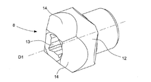
回転反射器8は、心棒4上にその周囲に組み付ける。したがって、回転反射器8は、心棒4と一体である。回転反射器8は、例えば、心棒4の端部分上に組み付けるが、心棒4上の反射器8のこの特定の構成は、本発明の文脈では限定されない。反射器8及び心棒4は、一体部品で作製することができる。回転反射器8は、反射器8自体が規則的に、特にほぼ一定速度で回転する際、回転反射器8の可視外側表面が変化するような形状を有し、この可視外側表面は、各発光器/検出器対10A、10Bから見え、各対10A、10Bのための反射器8の有効反射部分12を形成するものである。
The
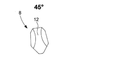
図2から図4で表す好ましい実施形態では、回転反射器8は、旋回円筒体から形成され、旋回円筒体の縁部上に、いくつかの連続する傾斜面取り部14が配置される。最初に説明した円筒体は、典型的には、約1.3mmの直径及び約0.77mmの長さを有する。傾斜面取り部14は、例えば、円筒体の2つの縁部上で、好ましくは対称に機械加工されている。円筒体は、その長手方向D1に、心棒4が通過する中心貫通口13を備える。反射器8の非面取り外側表面部12は、反射器8の有効反射部分を形成する。図2から図4の例示的な例では、回転反射器8は、4つの連続する傾斜面取り部14を有し、傾斜面取り部14は、同じ表面及び同じ勾配を有する。この場合、回転反射器8は、旋回対称性を有するが、このことは、本発明の文脈において制限されるものではない。他の構成は、実際、傾斜面取り部14が異なる表面及び/又は勾配を有し得ることが可能である。回転反射器8は、例えば金属である。そのような場合、反射器8の有効反射部分を形成する反射器8の非面取り外側表面部12は、好ましくは研磨されている。反射器8の金属は、好ましくは、研磨表面12が、発光器によって放出される光の波長を十分に反射するように選択される。例えば、赤外光発光器の場合、反射器8のために選択する金属は、金蒸着物としてもよい。したがって、反射器8の金属の選択は、選択する発光器の種類によって左右され、製品の制約条件に従って調節することができる。
In a preferred embodiment represented by FIGS. 2 to 4, the
好ましくは、各傾斜面取り部14は、反射器8の非面取り外側表面部12に接し長手方向D1に平行な平面に対して約50°に等しい角度を画定する。
Preferably, each inclined chamfered
各発光器/検出器対10A、10Bは、1つの光源16及び1つの光検出器18を含む。光源16は、典型的には、例えば赤外光を放出することができる1つ又は複数の発光ダイオード(複数可)から形成される。光源16及び光検出器18は、保護ケース20内に配置され、好ましくは、例えば分離壁により互いに光学的に隔離される。各発光器/検出器対10A、10Bは、例えば、近接センサ・ユニット・デバイスを形成する。
Each light emitter /
2つの発光器/検出器対10A、10Bは、反射器8に面して、回転反射器8の両側に配設される。図3に示す好ましい実施形態では、2つの発光器/検出器対10A、10Bは、回転反射器8に対して、2つの発光器16及び2つの検出器18がそれぞれ、互いに対して頭−尾で配置されるように構成する。好ましくは、図3に示すように、2つの発光器/検出器対10A、10Bは、中心が実質的に回転反射器8の中心22である円周上に置かれ、180°以外の値を有する角度だけ互いにずれる。
The two light emitter /
また、好ましくは、図3で見えるように、2つの発光器/検出器対10A、10B及び回転反射器8は、実質的にY字形状の空間構成を画定するように構成される。より正確には、回転反射器8は、Yの中心に配設され、第1の発光器/検出器対10Aは、Yの短腕の自由端に配設され、もう一方の発光器/検出器対10Bは、Yの長腕の自由端に配設される。言い換えれば、図3からわかるように、2つの発光器/検出器対10A、10Bは、回転反射器8の両側に配設され、互いに軸方向にずれる。
Also, preferably, as can be seen in FIG. 3, the two light emitter / detector pairs 10A, 10B and the
各光源16は、反射器8の一部を照明することを目的とする。各光検出器18は、反射器8から反射した光ビーム24を受光し、ビーム24を表現する電気信号を生成することを目的とする。面取り部14は、傾斜表面であるため、検出器18の方に光を反射させない。したがって、有効反射部分を形成する反射器8の可視外側表面12のみが、検出器18の方に光を反射させる。回転反射器8の形状は、反射器8自体が回転する際、回転反射器8の可視外側表面12が変化するようなものであり、このため、各検出器18が生成した表現的な電気信号は、反射器8自体が同じ回転方向S1、S2で回転すると、実質的に正弦曲線形状を有する。そのような信号26A、26Bは、例えば、図6で見ることができる。
Each
図5aから図5dは、反射器8の可視外側表面12の変化を示し、可視外側表面12は、検出器18の1つから見え、同じ回転方向S1、S2において、0°から180°までの反射器8の様々な角度位置で45°の段階を伴って回転する。反射器8の可視外側表面12は、反射器8自体が回転するにつれて、図5aからわかるように、最大の0°を通過することによって徐々に広がり、図5cからわかるように、最小の90°を通過することによって狭くなるように出現する。図5aから図5dに示す反射器8の可視表面12の間の比率の変化は、正弦と類似させることができる。図5aから図5dに示し、可視表面12が取る特定形状は、本発明の文脈において非限定的であることに留意されたい。各検出器18が生成した表現的な電気信号が、反射器8自体が回転する際に実質的に正弦曲線である限り、可視外側表面12に対する他の形状が可能である。
5a-5d show changes in the visible
プロセッサは、検出器18が生成した電気信号26A、26Bのそれぞれを処理するように構成される。プロセッサは、以下で詳細に説明するように、処理結果に従って、心棒4の角運動に関連する少なくとも1つのパラメータを決定するようにも構成される。決定されるパラメータ(複数可)は、例えば、心棒4の角度位置又は回転速度又は回転方向である。
The processor is configured to process each of the
図6は、異なる角度における検出器18からの2つの信号26A、26Bを表し、回転反射器8自体が、5°の段階で180°回転するのに対応する。各信号26A、26Bは、発光器/検出器対10A、10Bの一方のそれぞれの検出器18からのものである。各信号26A、26Bは、実質的に正弦曲線形状を有する。更に、図6の例示的な例では、信号26A、26Bの位相は、互いに約25°ずれる。好ましくは、信号26A、26Bの位相は、少なくとも25°、及び好ましくは約90°ずれる。
FIG. 6 represents two
次に、システム6のプロセッサによって実施される、心棒4の角運動に関連する少なくとも1つのパラメータを決定する本発明による方法を、図7及び図8を参照して説明する。最初に、ユーザが、例えばりゅうず2を操作することによって、心棒4を操作し、心棒4自体を長手方向D1回りに回転させ、時計1の時間を設定すると仮定する。この心棒4の回転により、回転反射器8の長手方向D1回りの回転を生じさせる。
Next, a method according to the present invention for determining at least one parameter related to the angular movement of the mandrel 4 performed by the processor of the
好ましくは、方法は、最初のステップ30を含み、ステップ30の間、プロセッサは、光源16のそれぞれの照明を交互に制御する。
Preferably, the method comprises the
最初のステップ、又はその後のステップ32の間、プロセッサは、2つの光検出器18から2つの電気信号26A、26Bを受信する。電気信号26A、26Bのそれぞれは、反射器8から反射された光ビーム24を表現し、実質的に正弦曲線形状を有する。
During the first step, or
次のステップ34の間、プロセッサは、2つの受信した正弦曲線信号26A、26Bのそれぞれの周波数を決定する。
During the
次のステップ36の間、プロセッサは、ステップ34の間に決定した周波数と、システム・メモリ手段内に事前に保存した対応表との間を比較することによって、心棒4の回転速度を決定する。
During the
好ましくは、方法は、並行ステップ又は次のステップ38を含み、ステップ38の間、プロセッサは、2つの受信した電気信号26A、26Bを同じ関数の正弦及び余弦として表現し、次に、変数が2つの信号の間の比率である逆正接関数を計算する。図6に示す信号26A、26Bの特定の例示的実施形態に対するこの計算結果を図8に表す。180°に対応する回転反射器8の半旋回周期に対して、得られる曲線39は直線であることに留意されたい。したがって、計算した逆正接関数の所与の値にアクセスするプロセッサは、この値から、心棒4の角度位置を明確に推測することができる。更に、得られる直線勾配の記号は、心棒4の回転方向の関数である。したがって、方法は、並行ステップ又は次のステップ40を含むことができ、ステップ40の間、プロセッサは、得られた直線勾配の記号を関数として、心棒4の回転方向を決定する。
Preferably, the method comprises a parallel step or the
図8に示す曲線39の形状を得るために、信号26A、26Bの位相は、好ましくは少なくとも25°ずれなければならないことに留意されたい。そのような位相のずれは、上記の発光器/検出器対10A、10Bの頭−尾構成、及び/又は上記の回転反射器8の両側の2つの発光器/検出器対10A、10Bの非対称構成によって得られる。したがって、信号26A、26Bの間で得られる位相のずれは、図8で表す曲線39の形状を得ることを可能にし、したがって、プロセッサが、心棒4の角度位置及び回転方向を正確に決定することを可能にする。
It should be noted that the phases of the
メモリ手段は、プログラム命令を含むコンピュータ・プログラム製品を保存し、コンピュータ・プログラム製品は、システム6によって実施されると、上記の方法を実施することができる。
The memory means stores the computer program product including the program instructions, and the computer program product can implement the above method when implemented by the
1 計時器
2 りゅうず
4 心棒
6 システム
8 回転反射器
10A 発光器/検出器対
10B 発光器/検出器対
12 非面取り外側表面部
14 傾斜面取り部
16 光源
18 光検出器
24 ビーム
26A 電気信号
26B 電気信号
1
Claims (14)
長手方向(D1)回りに回転することができるように構成された前記心棒(4)と、前記心棒(4)上かつ前記心棒(4)の周囲に組み付けられた回転反射器(8)と、前記回転反射器に面しながら前記回転反射器(8)の両側に配設され、かつ前記回転反射器(8)の一部を照明することを目的とする光源(16)、及び前記回転反射器(8)から反射した光ビーム(24)を受光し前記ビーム(24)を表現する電気信号(26A、26B)を生成することを目的とする光検出器(18)を備える2つの発光器/検出器対(10A、10B)と、前記検出器(18)が生成した前記電気信号のそれぞれを処理し、処理結果に応じて、前記心棒(4)の角運動に関連する前記少なくとも1つのパラメータを決定するように構成したプロセッサと
を備える、決定システム(6)において、
前記回転反射器(8)は、旋回円筒体から形成され、前記旋回円筒体の縁部上に、いくつかの連続する傾斜面取り部(14)が配置され、前記回転反射器(8)の非面取り外側表面部(12)は、各前記発光器/検出器対(10A、10B)から見え、かつ前記対のための前記回転反射器(8)の有効反射部分を形成し、前記有効反射部分は、前記回転反射器(8)自体が規則的に回転すると変化し、このため、前記回転反射器(8)自体が規則的に同じ回転方向(S1、S2)で回転すると、前記対(10A、10B)の前記検出器(18)が生成した表現的な電気信号(26A、26B)は、実質的に正弦曲線形状を有することを特徴とする、決定システム(6)。 A decision system (6) that determines at least one parameter related to the angular movement of the mandrel (4 ).
And the heart rod configured to be able to rotate the long side direction (D1) around (4), before Symbol mandrel (4) on and before Symbol rotary reflector assembled around the mandrel (4) ( source to 8), and intended to pre-SL is disposed on both sides of the SL before while facing the rotary reflector rotating reflector (8), and illuminates a part of the previous SL rotary reflector (8) ( 16), and the rotary reflector (8) photodetector which aims to generate an electrical signal representing the previous SL-beam (24) receives the reflected light beam (24) (26A, 26B) from ( two of Ru with a 18) emitter / detector pair (10A, and 10B), processes each of the electrical signals before Symbol detector (18) is generated, depending on the processing result, the mandrel (4) in the comprises <br/> configured the processor to determine at least one parameter, determination system related to the angular movement (6),
Said rotary reflector (8) is formed from the turning cylinder, the on edge of the revolving cylindrical body, a number of successive inclined chamfer (14) is placed, said rotary reflector (8) non chamfered outer surface portion (12) is visible from the said emitter / detector pair (10A, 10B), and forming the effective reflective portion of the rotating reflector (8) for the pair, the effective reflection The portion changes when the rotary reflector (8) itself rotates regularly, and therefore, when the rotary reflector (8) itself periodically rotates in the same rotation direction (S1, S2), the pair ( The determination system (6), characterized in that the expressive electrical signals (26A, 26B) generated by the detector (18) of 10A, 10B) have a substantially sinusoidal shape.
前記ステップ(32)において、2つの光検出器(18)からの2つの電気信号(26A、26B)であって、前記回転反射器(8)から反射した光ビーム(24)をそれぞれ表現し、かつ実質的に正弦曲線形状をそれぞれ有する電気信号(26A、26B)を受光し、In the step (32), two electric signals (26A, 26B) from the two photodetectors (18), respectively, representing the light beam (24) reflected from the rotary reflector (8). In addition, it receives electrical signals (26A, 26B) that have substantially sinusoidal shapes, respectively, and receives them.
前記ステップ(34)において、前記受信した2つの電気信号(26A、26B)のそれぞれの周波数を決定し、In the step (34), the frequencies of the two received electric signals (26A and 26B) are determined.
前記ステップ(36)において、前記プロセッサによって決定した前記周波数と、前記決定システム(6)のメモリ手段内に事前に保存した対応表との間の比較によって、前記心棒(4)の回転速度を決定する、In the step (36), the rotation speed of the mandrel (4) is determined by comparing the frequency determined by the processor with the correspondence table stored in advance in the memory means of the determination system (6). do,
方法。Method.
Applications Claiming Priority (2)
| Application Number | Priority Date | Filing Date | Title |
|---|---|---|---|
| EP18215440.1 | 2018-12-21 | ||
| EP18215440.1A EP3671135B1 (en) | 2018-12-21 | 2018-12-21 | System and method for determining at least one parameter relating to an angular movement of an axis |
Publications (2)
| Publication Number | Publication Date |
|---|---|
| JP2020101532A JP2020101532A (en) | 2020-07-02 |
| JP6970167B2 true JP6970167B2 (en) | 2021-11-24 |
Family
ID=64900811
Family Applications (1)
| Application Number | Title | Priority Date | Filing Date |
|---|---|---|---|
| JP2019220112A Active JP6970167B2 (en) | 2018-12-21 | 2019-12-05 | Systems and methods for determining at least one parameter associated with mandrel angular movement |
Country Status (4)
| Country | Link |
|---|---|
| US (1) | US11029648B2 (en) |
| EP (1) | EP3671135B1 (en) |
| JP (1) | JP6970167B2 (en) |
| CN (1) | CN111352336B (en) |
Families Citing this family (1)
| Publication number | Priority date | Publication date | Assignee | Title |
|---|---|---|---|---|
| EP3671134B1 (en) * | 2018-12-21 | 2022-09-21 | The Swatch Group Research and Development Ltd | System and method for determining at least one parameter relating to an angular movement of an axis |
Family Cites Families (13)
| Publication number | Priority date | Publication date | Assignee | Title |
|---|---|---|---|---|
| JPS6180013A (en) * | 1984-09-28 | 1986-04-23 | Alps Electric Co Ltd | Rotary encoder |
| JPS6222512U (en) * | 1985-07-25 | 1987-02-10 | ||
| JPH07159199A (en) * | 1993-12-13 | 1995-06-23 | Sharp Corp | High precision rotation type speed sensor |
| JP2005017011A (en) * | 2003-06-24 | 2005-01-20 | Seiko Epson Corp | Information processor, timepiece, and information processor control method, control program, and recording medium |
| EP2498147B1 (en) * | 2011-03-08 | 2016-06-22 | Montres Breguet SA | Ringer block and wake-up alarm drive mechanism for ringing timepiece |
| EP2884239B1 (en) * | 2013-12-13 | 2016-09-28 | The Swatch Group Research and Development Ltd. | Angular and axial position sensor arrangement |
| US9797753B1 (en) * | 2014-08-27 | 2017-10-24 | Apple Inc. | Spatial phase estimation for optical encoders |
| EP3015925B1 (en) | 2014-10-28 | 2020-07-15 | The Swatch Group Research and Development Ltd. | Optical position detection of a timepiece crown stem |
| EP3037898B1 (en) * | 2014-12-23 | 2017-06-21 | ETA SA Manufacture Horlogère Suisse | Electromechanical apparatus comprising a device for capacitive detection of the angular position of a moving element, and method for detecting the angular position of a moving element |
| EP3059643B1 (en) | 2015-02-23 | 2017-07-19 | Montres Breguet S.A. | Chronograph mechanism |
| WO2016141228A1 (en) | 2015-03-05 | 2016-09-09 | Apple Inc. | Optical encoder with direction-dependent optical properties |
| US9983029B2 (en) * | 2015-09-30 | 2018-05-29 | Apple Inc. | Integrated optical encoder for tilt able rotatable shaft |
| EP3333649A1 (en) | 2016-12-09 | 2018-06-13 | The Swatch Group Research and Development Ltd | Method for determining parameters for adjusting the operation of a mechanical watch |
-
2018
- 2018-12-21 EP EP18215440.1A patent/EP3671135B1/en active Active
-
2019
- 2019-11-12 US US16/680,988 patent/US11029648B2/en active Active
- 2019-12-05 JP JP2019220112A patent/JP6970167B2/en active Active
- 2019-12-20 CN CN201911325358.0A patent/CN111352336B/en active Active
Also Published As
| Publication number | Publication date |
|---|---|
| US11029648B2 (en) | 2021-06-08 |
| CN111352336A (en) | 2020-06-30 |
| EP3671135B1 (en) | 2022-08-17 |
| JP2020101532A (en) | 2020-07-02 |
| EP3671135A1 (en) | 2020-06-24 |
| CN111352336B (en) | 2022-02-11 |
| US20200201255A1 (en) | 2020-06-25 |
Similar Documents
| Publication | Publication Date | Title |
|---|---|---|
| JP5982051B2 (en) | Optical position detection of watch crown winding true | |
| US11002572B2 (en) | Optical encoder with direction-dependent optical properties comprising a spindle having an array of surface features defining a concave contour along a first direction and a convex contour along a second direction | |
| JP6147038B2 (en) | Position detecting device, lens device, imaging system, and machine tool | |
| JP5111243B2 (en) | Absolute encoder | |
| JP7030765B2 (en) | Systems and methods for determining at least one parameter associated with mandrel angular movement | |
| JP6970167B2 (en) | Systems and methods for determining at least one parameter associated with mandrel angular movement | |
| TW201525624A (en) | Device for detecting the position of watch hands | |
| JPH02285214A (en) | Length measuring machine and scale member used for the same | |
| JP2000028313A (en) | Apparatus having at least two coaxial wheels and means for detecting their angle positions and method for detecting the positions | |
| JP6519250B2 (en) | Switch device and electronic watch | |
| EP1186894A1 (en) | Angular speed sensor with reference mark | |
| CN109974575A (en) | For using the method and its equipment of automatic gain adjustment algorithm detection rotation angle | |
| JP7104217B2 (en) | Optical measuring device | |
| JP2006145466A (en) | Optical scale | |
| JPH06100467B2 (en) | Proximity sensor | |
| JP2016205855A (en) | Rotary encoder | |
| JPH11118470A (en) | Information of shaft position detecting device | |
| JP6665509B2 (en) | Position detection device | |
| JP2002054923A (en) | Angle measuring instrument of surveying device | |
| JP2011069620A (en) | Analog electronic clock | |
| JP2010230313A (en) | Method of manufacturing reflector and torque measuring device | |
| JP2001281000A5 (en) | ||
| RU99102837A (en) | METHOD FOR DETERMINING COMPONENTS OF MOVING A ROTATING OBJECT | |
| JPH11281401A (en) | Wave reshaping circuit, rotating detecting device and rotation detecting method |
Legal Events
| Date | Code | Title | Description |
|---|---|---|---|
| A621 | Written request for application examination |
Free format text: JAPANESE INTERMEDIATE CODE: A621 Effective date: 20191205 |
|
| A977 | Report on retrieval |
Free format text: JAPANESE INTERMEDIATE CODE: A971007 Effective date: 20201214 |
|
| A131 | Notification of reasons for refusal |
Free format text: JAPANESE INTERMEDIATE CODE: A131 Effective date: 20210112 |
|
| A521 | Request for written amendment filed |
Free format text: JAPANESE INTERMEDIATE CODE: A523 Effective date: 20210412 |
|
| A131 | Notification of reasons for refusal |
Free format text: JAPANESE INTERMEDIATE CODE: A131 Effective date: 20210629 |
|
| A521 | Request for written amendment filed |
Free format text: JAPANESE INTERMEDIATE CODE: A523 Effective date: 20210929 |
|
| TRDD | Decision of grant or rejection written | ||
| A01 | Written decision to grant a patent or to grant a registration (utility model) |
Free format text: JAPANESE INTERMEDIATE CODE: A01 Effective date: 20211026 |
|
| A61 | First payment of annual fees (during grant procedure) |
Free format text: JAPANESE INTERMEDIATE CODE: A61 Effective date: 20211028 |
|
| R150 | Certificate of patent or registration of utility model |
Ref document number: 6970167 Country of ref document: JP Free format text: JAPANESE INTERMEDIATE CODE: R150 |