JP6967983B2 - Image processing equipment, image processing methods, and programs - Google Patents
Image processing equipment, image processing methods, and programs Download PDFInfo
- Publication number
- JP6967983B2 JP6967983B2 JP2018011753A JP2018011753A JP6967983B2 JP 6967983 B2 JP6967983 B2 JP 6967983B2 JP 2018011753 A JP2018011753 A JP 2018011753A JP 2018011753 A JP2018011753 A JP 2018011753A JP 6967983 B2 JP6967983 B2 JP 6967983B2
- Authority
- JP
- Japan
- Prior art keywords
- medical image
- image
- landmark
- area
- region
- Prior art date
- Legal status (The legal status is an assumption and is not a legal conclusion. Google has not performed a legal analysis and makes no representation as to the accuracy of the status listed.)
- Active
Links
- 238000012545 processing Methods 0.000 title claims description 121
- 238000003672 processing method Methods 0.000 title claims description 27
- 238000000605 extraction Methods 0.000 claims description 63
- 230000006870 function Effects 0.000 claims description 53
- 238000000034 method Methods 0.000 claims description 42
- 230000008569 process Effects 0.000 claims description 26
- 210000000056 organ Anatomy 0.000 claims description 16
- 239000000284 extract Substances 0.000 claims description 12
- 238000011976 chest X-ray Methods 0.000 description 46
- 210000003128 head Anatomy 0.000 description 43
- 238000010801 machine learning Methods 0.000 description 36
- 238000010586 diagram Methods 0.000 description 30
- 210000000038 chest Anatomy 0.000 description 17
- 210000003109 clavicle Anatomy 0.000 description 15
- 210000005252 bulbus oculi Anatomy 0.000 description 13
- 238000004891 communication Methods 0.000 description 13
- 210000003625 skull Anatomy 0.000 description 13
- 210000000216 zygoma Anatomy 0.000 description 11
- 230000015654 memory Effects 0.000 description 10
- 210000001519 tissue Anatomy 0.000 description 10
- 230000008859 change Effects 0.000 description 9
- 238000003384 imaging method Methods 0.000 description 9
- 238000004458 analytical method Methods 0.000 description 8
- 238000013135 deep learning Methods 0.000 description 7
- 230000008054 signal transmission Effects 0.000 description 7
- 210000000988 bone and bone Anatomy 0.000 description 6
- 230000000694 effects Effects 0.000 description 6
- 210000004072 lung Anatomy 0.000 description 6
- 210000004556 brain Anatomy 0.000 description 5
- 238000013527 convolutional neural network Methods 0.000 description 5
- 210000001981 hip bone Anatomy 0.000 description 5
- 238000013528 artificial neural network Methods 0.000 description 4
- 238000004364 calculation method Methods 0.000 description 4
- 230000010365 information processing Effects 0.000 description 4
- 238000002595 magnetic resonance imaging Methods 0.000 description 4
- 206010002329 Aneurysm Diseases 0.000 description 2
- 206010016654 Fibrosis Diseases 0.000 description 2
- 206010028980 Neoplasm Diseases 0.000 description 2
- 230000009471 action Effects 0.000 description 2
- 210000000746 body region Anatomy 0.000 description 2
- 230000007882 cirrhosis Effects 0.000 description 2
- 208000019425 cirrhosis of liver Diseases 0.000 description 2
- 238000002591 computed tomography Methods 0.000 description 2
- 238000010191 image analysis Methods 0.000 description 2
- 210000001503 joint Anatomy 0.000 description 2
- 230000003902 lesion Effects 0.000 description 2
- 238000005259 measurement Methods 0.000 description 2
- 238000012986 modification Methods 0.000 description 2
- 230000004048 modification Effects 0.000 description 2
- 210000003205 muscle Anatomy 0.000 description 2
- 238000002600 positron emission tomography Methods 0.000 description 2
- 238000001356 surgical procedure Methods 0.000 description 2
- 210000002435 tendon Anatomy 0.000 description 2
- 210000000115 thoracic cavity Anatomy 0.000 description 2
- 238000013519 translation Methods 0.000 description 2
- PXFBZOLANLWPMH-UHFFFAOYSA-N 16-Epiaffinine Natural products C1C(C2=CC=CC=C2N2)=C2C(=O)CC2C(=CC)CN(C)C1C2CO PXFBZOLANLWPMH-UHFFFAOYSA-N 0.000 description 1
- 241000238366 Cephalopoda Species 0.000 description 1
- 230000000747 cardiac effect Effects 0.000 description 1
- 239000000470 constituent Substances 0.000 description 1
- 238000003745 diagnosis Methods 0.000 description 1
- 229940079593 drug Drugs 0.000 description 1
- 239000003814 drug Substances 0.000 description 1
- 238000011156 evaluation Methods 0.000 description 1
- 238000007689 inspection Methods 0.000 description 1
- 238000012804 iterative process Methods 0.000 description 1
- 238000004519 manufacturing process Methods 0.000 description 1
- 239000013307 optical fiber Substances 0.000 description 1
- 230000008855 peristalsis Effects 0.000 description 1
- 238000011176 pooling Methods 0.000 description 1
- 238000004549 pulsed laser deposition Methods 0.000 description 1
- 238000002601 radiography Methods 0.000 description 1
- 230000009467 reduction Effects 0.000 description 1
- 230000029058 respiratory gaseous exchange Effects 0.000 description 1
- 230000011218 segmentation Effects 0.000 description 1
- 239000004065 semiconductor Substances 0.000 description 1
- 230000009466 transformation Effects 0.000 description 1
Images


Classifications
-
- G—PHYSICS
- G06—COMPUTING; CALCULATING OR COUNTING
- G06T—IMAGE DATA PROCESSING OR GENERATION, IN GENERAL
- G06T7/00—Image analysis
- G06T7/0002—Inspection of images, e.g. flaw detection
- G06T7/0012—Biomedical image inspection
- G06T7/0014—Biomedical image inspection using an image reference approach
- G06T7/0016—Biomedical image inspection using an image reference approach involving temporal comparison
-
- G—PHYSICS
- G06—COMPUTING; CALCULATING OR COUNTING
- G06T—IMAGE DATA PROCESSING OR GENERATION, IN GENERAL
- G06T7/00—Image analysis
- G06T7/30—Determination of transform parameters for the alignment of images, i.e. image registration
- G06T7/33—Determination of transform parameters for the alignment of images, i.e. image registration using feature-based methods
-
- G—PHYSICS
- G06—COMPUTING; CALCULATING OR COUNTING
- G06T—IMAGE DATA PROCESSING OR GENERATION, IN GENERAL
- G06T5/00—Image enhancement or restoration
- G06T5/50—Image enhancement or restoration by the use of more than one image, e.g. averaging, subtraction
-
- G—PHYSICS
- G06—COMPUTING; CALCULATING OR COUNTING
- G06T—IMAGE DATA PROCESSING OR GENERATION, IN GENERAL
- G06T7/00—Image analysis
- G06T7/10—Segmentation; Edge detection
- G06T7/11—Region-based segmentation
-
- G—PHYSICS
- G06—COMPUTING; CALCULATING OR COUNTING
- G06T—IMAGE DATA PROCESSING OR GENERATION, IN GENERAL
- G06T7/00—Image analysis
- G06T7/30—Determination of transform parameters for the alignment of images, i.e. image registration
- G06T7/33—Determination of transform parameters for the alignment of images, i.e. image registration using feature-based methods
- G06T7/337—Determination of transform parameters for the alignment of images, i.e. image registration using feature-based methods involving reference images or patches
-
- G—PHYSICS
- G06—COMPUTING; CALCULATING OR COUNTING
- G06T—IMAGE DATA PROCESSING OR GENERATION, IN GENERAL
- G06T2207/00—Indexing scheme for image analysis or image enhancement
- G06T2207/10—Image acquisition modality
- G06T2207/10028—Range image; Depth image; 3D point clouds
-
- G—PHYSICS
- G06—COMPUTING; CALCULATING OR COUNTING
- G06T—IMAGE DATA PROCESSING OR GENERATION, IN GENERAL
- G06T2207/00—Indexing scheme for image analysis or image enhancement
- G06T2207/10—Image acquisition modality
- G06T2207/10072—Tomographic images
- G06T2207/10081—Computed x-ray tomography [CT]
-
- G—PHYSICS
- G06—COMPUTING; CALCULATING OR COUNTING
- G06T—IMAGE DATA PROCESSING OR GENERATION, IN GENERAL
- G06T2207/00—Indexing scheme for image analysis or image enhancement
- G06T2207/10—Image acquisition modality
- G06T2207/10072—Tomographic images
- G06T2207/10104—Positron emission tomography [PET]
-
- G—PHYSICS
- G06—COMPUTING; CALCULATING OR COUNTING
- G06T—IMAGE DATA PROCESSING OR GENERATION, IN GENERAL
- G06T2207/00—Indexing scheme for image analysis or image enhancement
- G06T2207/10—Image acquisition modality
- G06T2207/10116—X-ray image
-
- G—PHYSICS
- G06—COMPUTING; CALCULATING OR COUNTING
- G06T—IMAGE DATA PROCESSING OR GENERATION, IN GENERAL
- G06T2207/00—Indexing scheme for image analysis or image enhancement
- G06T2207/10—Image acquisition modality
- G06T2207/10132—Ultrasound image
-
- G—PHYSICS
- G06—COMPUTING; CALCULATING OR COUNTING
- G06T—IMAGE DATA PROCESSING OR GENERATION, IN GENERAL
- G06T2207/00—Indexing scheme for image analysis or image enhancement
- G06T2207/20—Special algorithmic details
- G06T2207/20081—Training; Learning
-
- G—PHYSICS
- G06—COMPUTING; CALCULATING OR COUNTING
- G06T—IMAGE DATA PROCESSING OR GENERATION, IN GENERAL
- G06T2207/00—Indexing scheme for image analysis or image enhancement
- G06T2207/20—Special algorithmic details
- G06T2207/20084—Artificial neural networks [ANN]
-
- G—PHYSICS
- G06—COMPUTING; CALCULATING OR COUNTING
- G06T—IMAGE DATA PROCESSING OR GENERATION, IN GENERAL
- G06T2207/00—Indexing scheme for image analysis or image enhancement
- G06T2207/20—Special algorithmic details
- G06T2207/20212—Image combination
-
- G—PHYSICS
- G06—COMPUTING; CALCULATING OR COUNTING
- G06T—IMAGE DATA PROCESSING OR GENERATION, IN GENERAL
- G06T2207/00—Indexing scheme for image analysis or image enhancement
- G06T2207/30—Subject of image; Context of image processing
- G06T2207/30004—Biomedical image processing
-
- G—PHYSICS
- G06—COMPUTING; CALCULATING OR COUNTING
- G06T—IMAGE DATA PROCESSING OR GENERATION, IN GENERAL
- G06T2207/00—Indexing scheme for image analysis or image enhancement
- G06T2207/30—Subject of image; Context of image processing
- G06T2207/30004—Biomedical image processing
- G06T2207/30061—Lung
Description
本発明は画像処理装置、画像処理方法、及びプログラムに係り、特に医用画像の位置合わせに関する。 The present invention relates to an image processing apparatus, an image processing method, and a program, and more particularly to alignment of a medical image.
医用画像診断の分野では、複数の医用画像に共通して含まれる特徴領域の比較等の解析が行われる。複数の医用画像の一例として、同一の対象について同一のモダリティを用いた撮像時点が異なる複数の医用画像が挙げられる。 In the field of medical image diagnosis, analysis such as comparison of feature areas commonly included in a plurality of medical images is performed. As an example of a plurality of medical images, there are a plurality of medical images using the same modality for the same object and having different imaging time points.
特許文献1は、過去に撮像された第1の医用画像に含まれる病変領域の画像と、最も直近に撮像された第2の医用画像に含まれる病変領域の画像との間で非剛体レジストレーションを行う医用画像計測装置が記載されている。同文献に記載の医用画像計測装置は、非剛体レジストレーションの結果として得られた画像変化量を用いて、第3の計測パラメータを取得している。
複数の医用画像の比較等の解析を行う際に、複数の医用画像の位置合わせを高精度に行うことが重要である。複数の医用画像の位置合わせを行う際に、位置合わせの基準となるランドマークが用いられる。 When performing analysis such as comparison of a plurality of medical images, it is important to perform alignment of the plurality of medical images with high accuracy. When aligning multiple medical images, landmarks that serve as a reference for alignment are used.
特許文献2は、複数の骨から構成される被検体を異なる時点で撮像した2つの画像の位置合わせを行う画像位置合わせ装置が記載されている。同文献に記載の画像位置合わせ装置は、骨の部位ごとに少なくとも3つのランドマークを設定し、少なくとも3つのランドマークを用いて位置合わせ処理を行う。
特許文献3は、第1の医用画像データと第2の医用画像データとの間の剛体領域に対して剛体位置合わせを行い、非剛体領域に対して非剛体位置合わせを行う医用画像処理装置が記載されている。
特許文献4は、手術の対象部位を含む術中画像と、対象部位の手術に関する関連画像との位置合わせを行う画像位置合わせ装置が記載されている。同文献に記載の画像位置合わせ装置は、関連画像と位置合わせ済みの術中画像と、新たに取得された術中画像から互いに対応する複数の特徴点を抽出する。
同文献に記載の画像位置合わせ装置は、優先度が設定された複数の特徴点に基づいて、関連画像と位置合わせ済みの術中画像と、新たに取得された術中画像との相対的な相違を表す位置情報に基づいて、関連画像と新たに取得された術中画像との位置合わせをする。優先度は、位置合わせを行う際に適した位置にある画素ほど、大きくなるように付与されている。 The image alignment device described in the same document determines the relative difference between the related image and the aligned intraoperative image and the newly acquired intraoperative image based on a plurality of prioritized feature points. Based on the displayed position information, the related image and the newly acquired intraoperative image are aligned. The priority is given so that the pixel at a position suitable for alignment is higher.
特許文献5は、超音波画像と同一断層面のMRI画像を取得する際に、体内のランドマークとなる複数の特徴部位を予め定めておき、特徴部位を基準にして検査体内での撮像面を相対的に決める方法が記載されている。同文献には、特徴部位として、呼吸、及び蠕動運動による影響が少ない骨格、及び臓器の輪郭を用いることができると記載されている。なお、MRIは、magnetic resonance imagingの省略語である。
In
しかしながら、特許文献1には、第1の医用画像と第2の医用画像との位置合わせに関する記載はない。
However,
特許文献2に記載の発明は、過去に撮像された3次元画像と今回撮像された3次元画像との間において椎骨領域の位置を合わせる際に、椎骨領域にランドマークを設定している。位置合わせの対象領域にランドマークが含まれる場合、被検体の姿勢等の違いに起因して、位置合わせの対象とされる複数の医用画像の間に傾き等の変化が生じた場合に、正確な位置合わせが困難である。
In the invention described in
特許文献3、及び特許文献4には複数の医用画像の位置合わせの基準とされるランドマーク領域に関する記載はなく、特許文献3に記載の発明、及び特許文献4に記載の発明は、ランドマーク領域を用いた複数の医用画像の位置合わせに関するものではない。
特許文献5に記載の発明は、超音波画像の評価結果に基づいて、超音波撮像装置以外の撮像装置を用いて撮像した画像を変形させ、2次元画像、又は3次元画像として表示するものであり、複数の医用画像の位置合わせを行うものではない。
The invention described in
また、特許文献5に記載の発明におけるランドマークは、検査体内での撮像面を相対的に決めるものであって、複数の医用画像の位置合わせの基準ではない。
Further, the landmark in the invention described in
本発明はこのような事情に鑑みてなされたもので、複数の医用画像について高精度の位置合わせを可能とする、画像処理装置、画像処理方法、及びプログラムを提供することを目的とする。 The present invention has been made in view of such circumstances, and an object of the present invention is to provide an image processing apparatus, an image processing method, and a program capable of highly accurate alignment of a plurality of medical images.
上記目的を達成するために、次の発明態様を提供する。 In order to achieve the above object, the following aspects of the invention are provided.
第1態様に係る画像処理装置は、比較する注目領域をそれぞれに含む第1医用画像、及び第2医用画像を含む複数の医用画像を取得する画像取得部と、第1医用画像、及び第2医用画像のそれぞれから、注目領域を含む複数の領域を抽出する抽出部と、第1医用画像の複数の領域、及び第2医用画像の複数の領域のうち、第1医用画像と第2医用画像とに共通する領域であり、注目領域と異なる特定の領域を、第1医用画像と第2医用画像との位置合わせの基準となるランドマーク領域として選択するランドマーク領域選択部と、ランドマーク領域を位置合わせの基準として、第1医用画像と第2医用画像との剛体レジストレーション、又は線形レジストレーションを行い、第1医用画像と第2医用画像とを重ね合わせた結果画像を生成する位置合わせ部と、を備えた画像処理装置である。 The image processing apparatus according to the first aspect has an image acquisition unit for acquiring a first medical image including a region of interest to be compared and a plurality of medical images including a second medical image, a first medical image, and a second medical image. Of the extraction unit that extracts a plurality of regions including the region of interest from each of the medical images, the plurality of regions of the first medical image, and the plurality of regions of the second medical image, the first medical image and the second medical image. A landmark area selection unit that selects a specific area that is common to and different from the area of interest as a landmark area that serves as a reference for alignment between the first medical image and the second medical image, and a landmark area. Rigid registration or linear registration between the first medical image and the second medical image is performed with It is an image processing device provided with a unit.
第1態様によれば、注目領域と異なる特定の領域がランドマーク領域として選択される。ランドマーク領域を基準として第1医用画像と第2医用画像との剛体レジストレーション、又は線形レジストレーションが行われる。これにより、第1医用画像と第2医用画像と高精度の位置合わせが可能である。 According to the first aspect, a specific area different from the area of interest is selected as the landmark area. Rigid body registration or linear registration between the first medical image and the second medical image is performed with reference to the landmark area. This enables highly accurate alignment between the first medical image and the second medical image.
注目領域は、第1医用画像、及び第2医用画像に含まれる領域であり、例えば、第1医用画像、及び第2医用画像における観察、及び計測等の解析対象の領域である。注目領域の例として臓器、及び組織等が挙げられる。組織の例として、骨、関節、腱、筋、腫瘍、及び瘤等が挙げられる。 The area of interest is an area included in the first medical image and the second medical image, and is, for example, an area to be analyzed such as observation and measurement in the first medical image and the second medical image. Examples of areas of interest include organs, tissues and the like. Examples of tissues include bones, joints, tendons, muscles, tumors, and aneurysms.
医用画像の一例として、モダリティを用いて被検体を撮像して得られたデジタル形式の医用画像が挙げられる。医用画像は2次元画像を適用してもよいし、3次元画像を適用してもよい。 An example of a medical image is a digital medical image obtained by imaging a subject using a modality. A two-dimensional image may be applied to the medical image, or a three-dimensional image may be applied.
ランドマーク領域選択部は、1つのランドマーク領域を選択してもよいし、複数のランドマーク領域を選択してもよい。 The landmark area selection unit may select one landmark area or may select a plurality of landmark areas.
第1態様に係る画像処理装置は、1つ以上のプロセッサと、1つ以上のメモリを備えた画像処理装置であって、プロセッサは、比較する注目領域をそれぞれに含む第1医用画像、及び第2医用画像を取得し、第1医用画像、及び第2医用画像のそれぞれから、注目領域を含む複数の領域を抽出し、第1医用画像の複数の領域、及び第2医用画像の複数の領域のうち、第1医用画像と第2医用画像とに共通する領域であり、注目領域と異なる特定の領域を、第1医用画像と第2医用画像との位置合わせの基準となるランドマーク領域として選択し、ランドマーク領域を位置合わせの基準として、第1医用画像と第2医用画像との剛体レジストレーション、又は線形レジストレーションを行い、第1医用画像と第2医用画像とを重ね合わせた結果画像を生成し、メモリは、各処理におけるデータを記憶する画像処理装置として構成し得る。 The image processing apparatus according to the first aspect is an image processing apparatus including one or more processors and one or more memories, wherein the processors include a first medical image including a region of interest to be compared, and a first medical image. 2 Medical images are acquired, and a plurality of regions including a region of interest are extracted from each of the first medical image and the second medical image, a plurality of regions of the first medical image, and a plurality of regions of the second medical image. Of these, a specific area that is common to the first medical image and the second medical image and is different from the area of interest is used as a landmark area that serves as a reference for alignment between the first medical image and the second medical image. The result of selecting, performing rigid registration or linear registration between the first medical image and the second medical image using the landmark area as the alignment reference, and superimposing the first medical image and the second medical image. The memory can be configured as an image processing device that generates an image and stores data in each process.
第2態様は、第1態様の画像処理装置において、第1医用画像の複数の領域、及び第2医用画像の複数の領域から、1以上の注目領域を選択する注目領域選択部を備えた構成としてもよい。 The second aspect is a configuration in which the image processing apparatus of the first aspect includes a region of interest selection unit that selects one or more regions of interest from a plurality of regions of a first medical image and a plurality of regions of a second medical image. May be.
第2態様によれば、第1医用画像、及び第2医用画像から抽出された領域から、1以上の任意の注目領域の選択が可能である。 According to the second aspect, one or more arbitrary regions of interest can be selected from the first medical image and the regions extracted from the second medical image.
第3態様は、第2態様の画像処理装置において、位置合わせ部は、注目領域選択部を用いて選択された注目領域を重ね合わせた結果画像を生成する構成としてもよい。 A third aspect may be configured in the image processing apparatus of the second aspect, in which the alignment unit may generate an image as a result of superimposing the areas of interest selected by using the area of interest selection unit.
第3態様によれば、第1医用画像と第2医用画像との比較等の解析が可能である。 According to the third aspect, it is possible to perform analysis such as comparison between the first medical image and the second medical image.
結果画像は注目領域を表示し、注目領域以外の領域を非表示としてもよい。 The result image may display the area of interest and hide areas other than the area of interest.
第4態様は、第1態様から第3態様のいずれか一態様の画像処理装置において、抽出部は、医用画像と領域の抽出結果との組、又は医用画像とランドマーク領域の選択結果との組を正解データとして学習した学習結果を用いて、領域の抽出を行う構成としてもよい。 A fourth aspect is the image processing apparatus according to any one of the first to third aspects, wherein the extraction unit is a set of a medical image and an extraction result of an area, or a selection result of a medical image and a landmark area. The region may be extracted using the learning result obtained by learning the set as the correct answer data.
第4態様によれば、正解データを用いて学習した学習結果を反映させた高精度の領域抽出が可能である。 According to the fourth aspect, it is possible to extract a region with high accuracy by reflecting the learning result learned by using the correct answer data.
第5態様は、第1態様から第4態様のいずれか一態様の画像処理装置において、抽出部は、医用画像と領域ごとの抽出結果との組、又は医用画像とランドマーク領域の選択結果との組を正解データとして、領域ごとに学習した学習結果を用いて、領域の抽出を行う構成としてもよい。 A fifth aspect is the image processing apparatus according to any one of the first to fourth aspects, wherein the extraction unit is a set of a medical image and an extraction result for each area, or a selection result of a medical image and a landmark area. The set of is used as the correct answer data, and the learning result learned for each area may be used to extract the area.
第5態様によれば、領域ごとの個別の正解データを用いた学習結果を反映させた高精度領域の抽出が可能である。 According to the fifth aspect, it is possible to extract a high-precision region that reflects the learning result using the individual correct answer data for each region.
第6態様は、第1態様から第5態様のいずれか一態様の画像処理装置において、第1医用画像、及び第2医用画像について、ランドマーク領域の候補とされるランドマーク候補領域を設定するランドマーク候補領域設定部を備えた構成としてもよい。 In the sixth aspect, in the image processing apparatus of any one of the first to fifth aspects, a landmark candidate area as a candidate for the landmark area is set for the first medical image and the second medical image. It may be configured to include a landmark candidate area setting unit.
第6態様によれば、第1医用画像、及び第2医用画像に適用したランドマーク候補領域の設定が可能である。 According to the sixth aspect, it is possible to set the landmark candidate area applied to the first medical image and the second medical image.
第6態様において、ランドマーク候補領域の設定情報を入力する入力装置を備える態様も可能である。 In the sixth aspect, it is also possible to include an input device for inputting the setting information of the landmark candidate area.
第7態様は、第6態様の画像処理装置において、ランドマーク候補領域設定部は、第1医用画像、及び第2医用画像の少なくともいずれか一方を構成する領域のうち、ランドマーク領域となり得る全ての領域をランドマーク候補領域として設定する構成としてもよい。 In the seventh aspect, in the image processing apparatus of the sixth aspect, the landmark candidate area setting unit is all the areas that can be the landmark area among the areas constituting at least one of the first medical image and the second medical image. The area may be set as a landmark candidate area.
第7態様によれば、ランドマーク領域となり得る全ての領域をランドマーク候補領域として設定することが可能である。 According to the seventh aspect, it is possible to set all the areas that can be landmark areas as landmark candidate areas.
第8態様は、第6態様又は第7態様の画像処理装置において、ランドマーク領域選択部は、ランドマーク候補領域のうち、第1医用画像、及び第2医用画像から抽出された領域の中から、ランドマーク領域を選択する構成としてもよい。 The eighth aspect is in the image processing apparatus of the sixth aspect or the seventh aspect, in which the landmark area selection part has a landmark area selected from the area extracted from the 1st medical image and the 2nd medical image among the landmark candidate areas. , The landmark area may be selected.
第8態様によれば、ランドマーク候補領域の中からランドマーク領域の選択が可能である。 According to the eighth aspect, the landmark area can be selected from the landmark candidate areas.
第8態様において、ランドマーク領域の選択情報を入力する入力装置を備える態様も可能である。 In the eighth aspect, it is also possible to include an input device for inputting selection information of the landmark area.
第9態様は、第6態様から第8態様のいずれか一態様の画像処理装置において、ランドマーク候補領域に優先度を設定する優先度設定部を備えた構成としてもよい。 The ninth aspect may be a configuration in which the image processing apparatus according to any one of the sixth to eighth aspects includes a priority setting unit for setting a priority in the landmark candidate area.
第9態様によれば、ランドマーク候補領域に設定された優先度に基づいてランドマーク領域を設定し得る。 According to the ninth aspect, the landmark area can be set based on the priority set in the landmark candidate area.
第10態様は、第9態様の画像処理装置において、ランドマーク領域選択部は、2つ以上のランドマーク候補領域が設定された場合に、それぞれのランドマーク候補領域の優先度が高い順に、1つ以上のランドマーク領域を選択する構成としてもよい。
In the tenth aspect, in the image processing apparatus of the ninth aspect, when two or more landmark candidate areas are set, the landmark
第10態様によれば、ランドマーク候補領域に設定された優先度の高い順にランドマーク領域を設定し得る。 According to the tenth aspect, the landmark area can be set in descending order of priority set in the landmark candidate area.
第10態様において、優先度の設定情報を入力する入力装置を備える態様も可能である。 In the tenth aspect, it is also possible to include an input device for inputting priority setting information.
第11態様は、第1態様から第10態様のいずれか一態様の画像処理装置において、ランドマーク領域選択部は、複数のランドマーク領域を選択し、位置合わせ部は、ランドマーク領域選択部を用いて選択された複数のランドマーク領域を用いて結果画像を生成する際に、ランドマーク領域の誤差が最小となる第1医用画像と第2医用画像と位置合わせを行う構成としてもよい。 In the eleventh aspect, in the image processing apparatus according to any one of the first to tenth aspects, the landmark area selection unit selects a plurality of landmark areas, and the alignment unit selects the landmark area selection unit. When the result image is generated using the plurality of landmark areas selected in use, the first medical image and the second medical image may be aligned so that the error of the landmark area is minimized.
第11態様によれば、複数のランドマークを用いた、第1医用画像と第2医用画像との高精度の位置合わせが可能である。 According to the eleventh aspect, it is possible to align the first medical image and the second medical image with high accuracy using a plurality of landmarks.
第12態様は、第1態様から第11態様のいずれか一態様の画像処理装置において、画像取得部は、同一の種類のモダリティを用いて生成された第1医用画像、及び第2医用画像を取得する構成としてもよい。 A twelfth aspect is an image processing apparatus according to any one of the first to eleventh aspects, wherein the image acquisition unit uses a first medical image and a second medical image generated by using the same type of modality. It may be a configuration to be acquired.
第12態様によれば、同一の種類のモダリティを用いて生成された第1医用画像と第2医用画像との位置合わせをした結果画像を生成し得る。 According to the twelfth aspect, it is possible to generate a result image by aligning the first medical image and the second medical image generated by using the same kind of modality.
第13態様は、第1態様から第12態様のいずれか一態様の画像処理装置において、第1医用画像、及び第2医用画像は、同一の患者における同一の被検体について、異なる時期に生成された医用画像が適用される構成としてもよい。 A thirteenth aspect is an image processing apparatus according to any one of the first to twelfth aspects, in which the first medical image and the second medical image are generated for the same subject in the same patient at different times. It may be configured to apply the medical image.
第13態様によれば、同一の患者における同一の被検体について、経時変化等の解析が可能である。 According to the thirteenth aspect, it is possible to analyze changes over time and the like for the same subject in the same patient.
第14態様は、第1態様から第13態様のいずれか一態様の画像処理装置において、結果画像を表す結果画像信号を表示装置へ送信する画像信号送信部を備えた構成としてもよい。 The fourteenth aspect may be a configuration in which the image processing device according to any one of the first to thirteenth aspects includes an image signal transmission unit that transmits a result image signal representing the result image to the display device.
第14態様によれば、表示装置を用いて結果画像を表示し得る。 According to the fourteenth aspect, the result image can be displayed by using the display device.
第15態様は、第14態様の画像処理装置において、表示装置へ結果画像の全体を表示させるか、又は表示装置へ結果画像の注目領域のみ表示させるかを選択する表示選択部を備えた構成としてもよい。 In the fifteenth aspect, the image processing apparatus of the fourteenth aspect includes a display selection unit for selecting whether to display the entire result image on the display device or to display only the region of interest of the result image on the display device. May be good.
第15態様によれば、結果画像の全体を表示させるか、又は結果画像の注目領域のみを表示させるかの選択が可能である。 According to the fifteenth aspect, it is possible to select whether to display the entire result image or only the area of interest of the result image.
第16態様に係る画像処理方法は、比較する注目領域をそれぞれに含む第1医用画像、及び第2医用画像を含む複数の医用画像を取得する画像取得工程と、第1医用画像、及び第2医用画像のそれぞれから、注目領域を含む複数の領域を抽出する抽出工程と、第1医用画像の複数の領域、及び第2医用画像の複数の領域のうち、第1医用画像と第2医用画像とに共通する領域であり、注目領域と異なる特定の領域を、第1医用画像と第2医用画像との位置合わせの基準となるランドマーク領域として選択するランドマーク領域選択工程と、ランドマーク領域を位置合わせの基準として、第1医用画像と第2医用画像との剛体レジストレーション、又は線形レジストレーションを行い、第1医用画像と第2医用画像とを重ね合わせた結果画像を生成する位置合わせ工程と、を含む画像処理方法である。 The image processing method according to the sixteenth aspect is an image acquisition step of acquiring a first medical image including a region of interest to be compared and a plurality of medical images including the second medical image, a first medical image, and a second. A first medical image and a second medical image out of an extraction step of extracting a plurality of regions including a region of interest from each of the medical images, a plurality of regions of the first medical image, and a plurality of regions of the second medical image. A landmark area selection step of selecting a specific area that is common to and different from the area of interest as a landmark area that serves as a reference for alignment between the first medical image and the second medical image, and a landmark area. Rigid registration or linear registration between the first medical image and the second medical image is performed with It is an image processing method including a step.
第16態様によれば、第1態様と同様の効果を得ることができる。 According to the 16th aspect, the same effect as that of the 1st aspect can be obtained.
第16態様において、第2態様から第15態様で特定した事項と同様の事項を適宜組み合わせることができる。その場合、画像処理装置において特定される処理や機能を担う構成要素は、これに対応する処理や機能を担う画像処理方法の構成要素として把握することができる。 In the 16th aspect, the same items as those specified in the 2nd to 15th aspects can be appropriately combined. In that case, the component responsible for the process or function specified in the image processing apparatus can be grasped as the component of the image processing method responsible for the corresponding process or function.
第17態様に係るプログラムは、コンピュータに、比較する注目領域をそれぞれに含む第1医用画像、及び第2医用画像を含む複数の医用画像を取得する画像取得機能、第1医用画像、及び第2医用画像のそれぞれから、注目領域を含む複数の領域を抽出する抽出機能、第1医用画像の複数の領域、及び第2医用画像の複数の領域のうち、第1医用画像と第2医用画像とに共通する領域であり、注目領域と異なる特定の領域を、第1医用画像と第2医用画像との位置合わせの基準となるランドマーク領域として選択するランドマーク領域選択機能、及びランドマーク領域を位置合わせの基準として、第1医用画像と第2医用画像との剛体レジストレーション、又は線形レジストレーションを行い、第1医用画像と第2医用画像とを重ね合わせた結果画像を生成する位置合わせ機能を実現させるプログラムである。 The program according to the seventeenth aspect has an image acquisition function for acquiring a first medical image including a region of interest to be compared, and a plurality of medical images including the second medical image, a first medical image, and a second. Of the extraction function for extracting a plurality of regions including the region of interest from each of the medical images, the plurality of regions of the first medical image, and the plurality of regions of the second medical image, the first medical image and the second medical image A landmark area selection function that selects a specific area that is common to the above and is different from the area of interest as a landmark area that serves as a reference for alignment between the first medical image and the second medical image, and a landmark area. As a reference for alignment, a positioning function that performs rigid registration or linear registration between the first medical image and the second medical image and generates a result image by superimposing the first medical image and the second medical image. It is a program that realizes.
第17態様によれば、第1態様と同様の効果を得ることができる。 According to the 17th aspect, the same effect as that of the 1st aspect can be obtained.
第17態様において、第2態様から第15態様で特定した事項と同様の事項を適宜組み合わせることができる。その場合、画像処理装置において特定される処理や機能を担う構成要素は、これに対応する処理や機能を担うプログラムの構成要素として把握することができる。 In the 17th aspect, the same items as those specified in the 2nd to 15th aspects can be appropriately combined. In that case, the component responsible for the process or function specified in the image processing device can be grasped as the component of the program responsible for the corresponding process or function.
本発明によれば、注目領域と異なる特定の領域がランドマーク領域として選択される。ランドマーク領域を基準として第1医用画像と第2医用画像との剛体レジストレーション、又は線形レジストレーションが行われる。これにより、第1医用画像と第2医用画像と高精度の位置合わせが可能である。 According to the present invention, a specific region different from the region of interest is selected as the landmark region. Rigid body registration or linear registration between the first medical image and the second medical image is performed with reference to the landmark area. This enables highly accurate alignment between the first medical image and the second medical image.
以下、添付図面に従って本発明の好ましい実施の形態について詳説する。本明細書では、同一の構成要素には同一の参照符号を付して、重複する説明を省略する。 Hereinafter, preferred embodiments of the present invention will be described in detail with reference to the accompanying drawings. In the present specification, the same components are designated by the same reference numerals, and duplicate description is omitted.
[医療情報システムの全体構成]
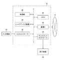
図1は実施形態に係る医療情報システムの構成例を示すブロック図である。医療情報システム10は、画像処理装置12、モダリティ14、及び画像データベース16を備える。画像処理装置12、モダリティ14、及び画像データベース16は、ネットワーク18を介して通信可能に接続される。医療情報システム10の例として、PACS(Picture Archiving and Communication System)が挙げられる。
[Overall configuration of medical information system]
FIG. 1 is a block diagram showing a configuration example of a medical information system according to an embodiment. The
画像処理装置12は、医療機関に備えられるコンピュータを適用可能である。画像処理装置12は、入力装置としてマウス20、及びキーボード22が接続される。また、画像処理装置12は、表示装置24が接続される。
The
モダリティ14は、被写体の検査対象部位を撮像し、医用画像を生成する撮像装置である。モダリティの例として、X線撮像装置、CT装置、MRI装置、PET装置、超音波装置、及び平面X線検出器を用いたCR装置が挙げられる。
The
CTはコンピュータ断層撮影を表すComputed Tomographyの省略語である。PET装置は陽電子放射断層撮影を表すPositron Emission Tomographyの省略語である。平面X線検出器はFPD(flat panel detector)と呼ばれることがある。CRはコンピュータX線撮影装置を表すComputed Radiographyの省略語である。 CT is an abbreviation for Computed Tomography, which stands for computed tomography. PET device is an abbreviation for Positron Emission Tomography, which stands for positron emission tomography. A flat panel detector is sometimes called an FPD (flat panel detector). CR is an abbreviation for Computed Radiography, which stands for computer radiographer.
医用画像のフォーマットは、DICOM規格を適用可能である。医用画像は、DICOM規格において規定された付帯情報が付加されてもよい。なお、DICOMはDigital Imaging and Communications in Medicineの省略語である。 The DICOM standard can be applied to the format of medical images. Ancillary information specified in the DICOM standard may be added to the medical image. DICOM is an abbreviation for Digital Imaging and Communications in Medicine.
画像データベース16は、大容量ストレージ装置を備えるコンピュータを適用可能である。コンピュータはデータベース管理システムの機能を提供するソフトウェアが組み込まれる。データベース管理システムは、DBMS(Data Base Management System)と呼ばれることがある。
The
ネットワーク18は、LAN(Local Area Network)を適用可能である。ネットワーク18はWAN(Wide Area Network)を適用してもよい。ネットワーク18の通信プロトコルは、DICOM規格を適用可能である。なお、ネットワーク18は公衆回線網に接続可能に構成されてもよいし、専用回線網に接続可能に構成されてもよい。ネットワーク18は、有線でもよいし、無線でもよい。
A LAN (Local Area Network) can be applied to the
[画像処理装置の構成]
〔ハードウェア構成〕
図2は画像処理装置のハードウェアの構成例を示すブロック図である。画像処理装置12は、制御部30、メモリ32、ハードディスク装置34、通信インターフェース36、入力コントローラ38、及びディスプレイコントローラ39を備える。
[Configuration of image processing device]
[Hardware configuration]
FIG. 2 is a block diagram showing an example of hardware configuration of an image processing device. The
〈制御部〉
制御部30は、画像処理装置12の全体制御部、各種演算部、及び記憶制御部として機能する。制御部30は、メモリ32に具備されるROM(read only memory)に記憶されているプログラムを実行する。制御部30は、通信インターフェース36を介して、外部の記憶装置からプログラムをダウンロードし、ダウンロードしたプログラムを実行してもよい。外部の記憶装置は、ネットワーク18を介して画像処理装置12と通信可能に接続されていてもよい。
<Control unit>
The
制御部30は、メモリ32に具備されるRAM(random access memory)を演算領域とし、各種プログラムと協働して、各種処理を実行する。これにより、画像処理装置12の各種機能が実現される。
The
制御部30は、ハードディスク装置34からのデータの読み出し、及びハードディスク装置34へのデータの書き込みを制御する。制御部30は、1つ又は2つ以上のプロセッサ(processor)が含まれてもよい。
The
プロセッサの一例として、FPGA(Field Programmable Gate Array)、及びPLD(Programmable Logic Device)等が挙げられる。FPGA、及びPLDは、製造後に回路構成の変更を可能とする。 Examples of the processor include FPGA (Field Programmable Gate Array), PLD (Programmable Logic Device) and the like. FPGA and PLD allow the circuit configuration to be changed after manufacturing.
プロセッサの他の例として、ASIC(Application Specific Integrated Circuit)が挙げられる。ASICは、特定の処理を実行させるために専用に設計された回路構成を備える。 Another example of a processor is an ASIC (Application Specific Integrated Circuit). The ASIC comprises a circuit configuration specifically designed to perform a particular process.
制御部30は、同じ種類の2以上のプロセッサを適用可能である。例えば、制御部30は2つ以上のFPGAを用いてもよいし、2つのPLDを用いてもよい。制御部30は、異なる種類の2つ以上プロセッサを適用してもよい。例えば、制御部30は1つ以上のFPGAと1つ以上のASICとを適用してもよい。
The
複数の制御部を備える場合、複数の制御部は1つのプロセッサを用いて構成してもよい。複数の制御部を1つのプロセッサで構成する一例として、1つ以上のCPU(Central Processing Unit)とソフトウェアとの組合せを用いて1つのプロセッサを構成し、このプロセッサが複数の制御部として機能する形態がある。CPUに代わり、又はCPUと併用して、画像処理に特化したプロセッサであるGPU(Graphics Processing Unit)を適用してもよい。なお、ここでいうソフトウェアはプログラムと同義である。複数の制御部が1つのプロセッサを用いて構成される代表例として、クライアント装置、及びサーバ装置等のコンピュータが挙げられる。 When a plurality of control units are provided, the plurality of control units may be configured by using one processor. As an example of configuring a plurality of control units with one processor, one processor is configured by using a combination of one or more CPUs (Central Processing Units) and software, and this processor functions as a plurality of control units. There is. A GPU (Graphics Processing Unit), which is a processor specialized in image processing, may be applied instead of the CPU or in combination with the CPU. The software here is synonymous with a program. A typical example in which a plurality of control units are configured by using one processor is a computer such as a client device and a server device.
複数の制御部を1つのプロセッサで構成する他の例として、複数の制御部を含むシステム全体の機能を1つのICチップで実現するプロセッサを使用する形態が挙げられる。複数の制御部を含むシステム全体の機能を1つのICチップで実現するプロセッサの代表例として、SoC(System On Chip)が挙げられる。なお、ICは、Integrated Circuitの省略語である。 As another example in which a plurality of control units are configured by one processor, there is a mode in which a processor that realizes the functions of the entire system including the plurality of control units with one IC chip is used. SoC (System On Chip) is a typical example of a processor that realizes the functions of the entire system including a plurality of control units with one IC chip. IC is an abbreviation for Integrated Circuit.
このように、制御部30は、ハードウェア的な構造として、各種のプロセッサを1つ以上用いて構成される。
As described above, the
〈メモリ〉
メモリ32は、図示しないROM、及び図示しないRAMを備える。ROMは、画像処理装置12において実行される各種プログラムを記憶する。ROMは、各種プログラムの実行に用いられるパラメータ、及びファイル等を記憶する。RAMは、データの一時記憶領域、及び制御部30のワーク領域等として機能する。
<memory>
The
〈ハードディスク装置〉
ハードディスク装置34は、各種データを非一時的に記憶する。具体的には、ハードディスク装置34は医用画像等を記憶する。ハードディスク装置34は、画像処理装置12の外部に外付けされてもよい。ハードディスク装置34に代わり、又はこれと併用して、大容量の半導体メモリ装置を適用してもよい。
<Hard disk device>
The
〈通信インターフェース〉
通信インターフェース36は、図1に示したモダリティ14、及び画像データベース16などの外部の装置との間のデータ通信を行う。図2に示したIFは、interfaceの省略後である。
<Communication interface>
The
〈入力コントローラ〉
入力コントローラ38は、マウス20、及びキーボード22等の入力装置26から送信される信号を受信し、画像処理装置12に適用される形式の信号に変換するインターフェースである。
<Input controller>
The
〈ディスプレイコントローラ〉
ディスプレイコントローラ39は、画像処理装置12において生成された画像を表す信号を、表示装置24を用いて表示させる映像信号に変換するインターフェースである。ディスプレイコントローラ39は、画像を表す映像信号を表示装置24へ送信する。
<Display controller>
The
なお、図2に示した画像処理装置12のハードウェア構成は一例であり、適宜、追加、削除、及び変更が可能である。
The hardware configuration of the
〔画像処理装置の機能〕
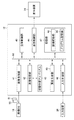
図3は画像処理装置の機能を示す機能ブロック図である。図3に示した画像処理装置12は、全体制御部40、画像取得部41、画像処理部42、表示制御部44、画面生成部45、入力制御部46、及び記憶部47を備える。
[Functions of image processing device]
FIG. 3 is a functional block diagram showing the functions of the image processing device. The
全体制御部40、画像取得部41、画像処理部42、表示制御部44、画面生成部45、入力制御部46、及び記憶部47は、通信信号線60を介して相互に通信可能に接続される。以下、各部について詳細に説明する。
The
〈全体制御部〉
全体制御部40は、画像処理装置12の制御プログラムの実行に基づき、画像取得部41、画像処理部42、表示制御部44、画面生成部45、入力制御部46、及び記憶部47を統括的に制御する。
<Overall control unit>
The
〈画像取得部〉
画像取得部41は、図1に示した画像データベース16に記憶される医用画像を取得する。画像データベース16は、モダリティ14を用いて撮像され医用画像が記憶される。本実施形態では、X線撮像装置を用いて撮像された胸部X線画像、及びCT装置を用いて撮像された頭部CT画像を医用画像として例示する。
<Image acquisition unit>
画像取得部41は、同一の注目領域が含まれる第1医用画像50、及び第2医用画像51を取得する。第1医用画像50の例として、任意の被検者の医用画像であり、過去に撮像された医用画像が挙げられる。第2医用画像51の例として、第1医用画像50と同一の被検者における現在の医用画像が挙げられる。
The
なお、第1医用画像50は、複数でもよい。すなわち、画像取得部41は、同一の注目領域が含まれる3つ以上の医用画像を取得してもよい。3つ以上の医用画像の一例として、2つ以上の過去画像、及び現在画像を含む例が挙げられる。また、第1医用画像50、及び第2医用画像51を撮像時期が異なる過去の医用画像としてもよい。
The number of the first
〈画像処理部〉
画像処理部42は、深層学習アルゴリズム43に基づく深層学習を用いて、画像取得部41を用いて取得した医用画像の解析処理を実行する。医用画像の解析処理の詳細は後述する。
<Image processing unit>
The
深層学習アルゴリズム43は、公知のコンボリューションニューラルネットワークの手法と、全結合層と、出力層とを含むアルゴリズムである。深層学習はディープラーニングと呼ばれることがある。
The
コンボリューションニューラルネットワークは、畳み込み層、及びプーリング層の繰り返し処理である。コンボリューションニューラルネットワークは、畳み込みニューラルネットワークと呼ばれる場合がある。なお、深層学習を用いた画像解析処理は公知技術であるので、具体的な説明は省略する。コンボリューションニューラルネットワークはCNNと表されることがある。CNNは、Convolutional Neural Networkの省略語である。 The convolution neural network is an iterative process of the convolution layer and the pooling layer. Convolutional neural networks are sometimes referred to as convolutional neural networks. Since the image analysis process using deep learning is a known technique, a specific description thereof will be omitted. Convolution neural networks are sometimes referred to as CNNs. CNN is an abbreviation for Convolutional Neural Network.
〈表示制御部〉
表示制御部44は、表示装置24を用いて医用画像を再生する際に、画像表示を制御するディスプレイドライバーとして機能する。表示制御部44は、表示装置24を用いて、医用画像に各種情報を重畳表示させてもよい。医用画像の表示の詳細は後述する。
<Display control unit>
The
表示制御部44は、表示装置24を用いて、各種選択画面、及び各種設定画像等の各種画面を表示させる。各種画面の表示の詳細は後述する。
The
〈画面生成部〉
画面生成部45は、表示装置24に表示させる各種操作画面を生成する。画面生成部45は表示制御部44を介して各種操作画面を表示装置24に表示させる。操作画面とは、複数の選択肢の中から1つ以上の選択を行う選択画面、及び1つ以上の処理パラメータを設定する設定画面等が挙げられる。
<Screen generator>
The
選択画面の例として、結果画像の表示形態を選択する表示選択画面が挙げられる。表示選択画面は、図8に符号140を付して図示する。設定画面の例として、ランドマーク領域の優先度を設定する優先度設定画面が挙げられる。優先度設定画面は、図14に符号260を付して図示する。
As an example of the selection screen, there is a display selection screen for selecting the display form of the result image. The display selection screen is illustrated with
〈入力制御部〉
入力制御部46は、入力装置26から入力された信号を、画像処理装置12に適用される形式の信号に変換し、変換後の信号を全体制御部40へ送信する。全体制御部40は、入力装置26から入力された情報に基づいて、画像処理装置12の各部を制御する。
<Input control unit>
The
〈記憶部〉
記憶部47は、画像記憶部48、及びプログラム記憶部49を備える。画像記憶部48は、画像取得部41を用いて取得した医用画像を記憶する。画像記憶部48に記憶された画像は、全体制御部40の制御の下、画像処理部42へ読み出される。画像記憶部48は、画像処理部42を用いた処理結果である結果画像を記憶する。
<Memory unit>
The
プログラム記憶部49は、画像処理装置12を動作させる各種プログラムを記憶する。プログラム記憶部49に記憶された各種プログラムは、全体制御部40の制御の下、各部へ読み出される。
The
〔第1実施形態に係る画像処理部の構成例〕
図4は第1実施形態に係る画像処理部の機能を示す機能ブロック図である。画像処理部42は、抽出部52、注目領域選択部54、ランドマーク候補領域設定部55、ランドマーク領域選択部56、位置合わせ部58、及び表示選択部59を備える。以下に、画像処理部42を構成する各部を詳細に説明する。
[Structure example of the image processing unit according to the first embodiment]
FIG. 4 is a functional block diagram showing the functions of the image processing unit according to the first embodiment. The
〈抽出部〉
抽出部52は、図3に示した画像取得部41を用いて取得した第1医用画像50、及び第2医用画像51のそれぞれから臓器領域、及び組織領域を抽出する。組織とは、骨、関節、腱、筋、腫瘍、及び瘤等の、臓器に属さない人体の構造を含む概念を表す。抽出はセグメンテーションと同義である。
<Extractor>
The
抽出部52は、臓器領域の特徴量、及び組織領域の特徴量を学習した機械学習器53が適用される。すなわち、抽出部52は、機械学習器53の学習結果に基づく抽出規則を用いて、医用画像から臓器領域、及び組織領域を抽出する。ここでいう医用画像は、第1医用画像50、及び第2医用画像51の総称である。
A
本実施形態には、医用画像と臓器領域との対応関係、及び医用画像と組織領域との対応関係の少なくともいずれかが含まれる正解データ53Aを用いて機械学習を行う機械学習器53を例示する。機械学習器53は、領域のごとに機械学習を実行してもよい。例えば、胸部X画像において、心臓ごと、及び鎖骨ごとなど、臓器ごと、及び組織ごとの学習を実行してもよい。機械学習器53は、医用画像とランドマーク領域の選択結果との対応関係を正解データとして学習してもよい。なお、ランドマーク領域の選択については後述する。
The present embodiment exemplifies a
〈注目領域選択部〉
注目領域選択部54は、第1医用画像50、及び第2医用画像51から、抽出部52を用いて抽出された臓器領域、及び組織領域の中から1以上の注目領域を選択する。注目領域は位置合わせの対象領域である。
<Attention area selection section>
The attention
例えば、注目領域として、胸部X線画像における心臓領域を設定した場合、第1医用画像50と第2医用画像51との位置を合わせて重ね合わせることで、第1医用画像50の心臓領域と第2医用画像の心臓領域との比較等の解析が可能となる。注目領域選択部54を用いた注目領域の選択情報は、図3に示した記憶部47に記憶される。注目領域選択部54は、入力装置26を用いて入力された注目領域選択情報を表す信号に基づいて、注目領域を設定することが可能である。
For example, when the heart region in the chest X-ray image is set as the region of interest, the heart region of the first
〈ランドマーク候補領域設定部〉
ランドマーク候補領域設定部55は、予めランドマーク候補領域を規定する。ランドマーク候補領域は、図示しないランドマーク候補領域記憶部を用いて記憶される。ランドマーク候補領域記憶部は、図3に示した記憶部47に具備されてもよい。
<Landmark candidate area setting unit>
The landmark candidate
ランドマーク候補領域設定部55は、第1医用画像50、及び第2医用画像51を構成する全ての領域のうち、ランドマーク領域となり得る全ての領域をランドマーク候補領域として設定し得る。
The landmark candidate
ランドマーク候補領域設定部55は、被検体ごと、及び医用画像を生成するモダリティごとに、ランドマーク候補領域を規定してもよい。すなわち、ランドマーク候補領域設定部55は、医用画像の種類ごとに、ランドマーク候補領域を規定してもよい。
The landmark candidate
ランドマーク候補領域とは、複数の医用画像の位置合わせを行う際の基準とされるランドマーク領域として使用可能な臓器、及び組織である。ランドマーク候補領域設定部55は、入力装置26を用いて入力されたランドマーク候補領域設定情報を表す信号に基づいて、ランドマーク候補領域を設定することが可能である。
The landmark candidate area is an organ or tissue that can be used as a landmark area as a reference when aligning a plurality of medical images. The landmark candidate
ランドマーク候補領域は、解剖学的特徴の変化が許容範囲内であるものが適用される。変化の許容範囲は、医用画像の種類、及びランドマーク候補領域の種類等の条件等に応じて適宜規定し得る。ランドマーク候補領域は、解剖学的特徴が変化しないものが好ましい。ここでいう変化しないものとは、実際には変化するものであるが、変化が無視できる程度の実質的に変化しないものが含まれてもよい。解剖学的特徴の変化の例として、経時変化が挙げられる。 Landmark candidate areas that are within the permissible range of changes in anatomical features are applied. The permissible range of change can be appropriately defined according to conditions such as the type of medical image and the type of landmark candidate area. The landmark candidate area is preferably one in which the anatomical features do not change. What does not change here is something that actually changes, but may include things that do not change substantially to the extent that the change is negligible. An example of changes in anatomical features is changes over time.
また、ランドマーク候補領域は、位置の移動が許容範囲内であるものが適用される。位置の移動の許容範囲内は、医用画像の種類、及びランドマーク候補領域の種類等の条件等に応じて適宜規定し得る。 In addition, the landmark candidate area to which the movement of the position is within the allowable range is applied. The permissible range of position movement can be appropriately defined according to conditions such as the type of medical image and the type of landmark candidate area.
〈ランドマーク領域選択部〉
ランドマーク領域選択部56は、ランドマーク候補領域設定部55を用いて設定されたランドマーク候補領域の中から、第1医用画像50、及び第2医用画像51の両者から抽出された領域であり、注目領域以外の領域をランドマーク領域として選択する。ランドマーク領域選択部56は、複数のランドマーク領域を選択してもよい。ランドマーク領域選択部56は、入力装置26を用いて入力されたランドマーク領域選択情報を表す信号に基づいて、ランドマーク領域を選択することが可能である。
<Landmark area selection section>
The landmark
ランドマーク領域選択部56を用いたランドマーク領域の選択情報は、図示しないランドマーク領域選択情報記憶部を用いて記憶される。ランドマーク領域選択情報記憶部は、図3に示した記憶部47に具備されてもよい。
The landmark area selection information using the landmark
〈位置合わせ部〉
位置合わせ部58は、注目領域の選択情報、及びランドマーク領域の選択情報を用いて、第1医用画像50と第2医用画像51との位置合わせを行う。位置合わせ部58は、第1医用画像50のランドマーク領域と、第2医用画像51のランドマーク領域との位置を合わせる。第1医用画像50と第2医用画像51との位置合わせは、平行移動、及び回転の少なくともいずれか一方を行う剛体位置合わせが適用される。平行移動、及び回転は、第1医用画像50、及び第2医用画像51の少なくともいずれか一方について行われる。
<Alignment part>
The
剛体位置合わせは、公知の手法を適用可能である。なお、剛体位置合わせは剛体レジストレーションと同義である。第1医用画像50と第2医用画像51とが変形を伴わない拡大、又は縮小の関係を有する場合、第1医用画像50と第2医用画像51との位置合わせは、アフィン変換等の公知の線形レジストレーションを適用可能である。
A known method can be applied to the rigid body alignment. Rigid body alignment is synonymous with rigid body registration. When the first
位置合わせ部58は、第1医用画像と第2画像との誤差を算出する誤差算出部58Aを備える。複数のランドマーク領域が用いられる場合、それぞれのランドマーク領域の位置が一致しないことがあり得る。
The
複数のランドマーク領域が用いられる場合、位置合わせ部58は、第1医用画像50と第2画像との誤差が最小となる、第1医用画像50と第2医用画像51との位置合わせを行う。第1医用画像50と第2画像との誤差は、各ランドマーク領域の誤差の統計値を適用し得る。統計値は、合計値、及び算術平均値等を適用可能である。
When a plurality of landmark areas are used, the
位置合わせ部58は、第1医用画像50と第2医用画像51とを重ね合わせた結果画像を生成する。結果画像は、記憶部47を用いて記憶される。位置合わせ部58は、結果画像を表す結果画像信号を表示制御部44へ送信する。位置合わせ部58は、構成要素として、結果画像信号を表示制御部44へ送信する画像信号送信部を備えてもよい。結果画像を表す結果画像信号を受信した表示制御部44は、表示装置24を用いて結果画像を表示する。
The
〈表示選択部〉
表示選択部59は、結果画像の全体を表示させるか、又は結果画像の注目領域のみを表示させるかを表す選択信号を位置合わせ部58へ送信する。位置合わせ部58は、表示選択部59から送信された選択信号に基づいて、結果画像の全体を表す結果画像信号、又は結果画像の注目領域のみを表す結果画像信号のいずれかを表示制御部44へ送信する。
<Display selection section>
The
表示制御部44は、位置合わせ部58から送信された結果画像信号に基づいて、結果画像の全体、又は結果画像の注目領域のみを、表示装置24を用いて表示する。
The
表示選択部59は、入力装置26を用いて入力された表示選択情報を表す信号に基づいて、結果画像の表示形態を選択することが可能である。
The
〔画像処理方法の手順〕
図5は第1実施形態に係る画像処理方法の手順の流れを示すフローチャートである。医用画像取得工程S10では、図3に示した画像取得部41は、第1医用画像50、及び第2医用画像51を取得する。医用画像取得工程S10の後に、抽出工程S12へ進む。
[Procedure of image processing method]
FIG. 5 is a flowchart showing the flow of the procedure of the image processing method according to the first embodiment. In the medical image acquisition step S10, the
抽出工程S12では、図4に示した抽出部52は、第1医用画像50、及び第2医用画像51の両方に含まれる領域を抽出する。抽出工程S12の後に、注目領域選択工程S14へ進む。
In the extraction step S12, the
注目領域選択工程S14では、注目領域選択部54は、抽出工程S12において抽出された領域から注目領域を選択する。注目領域選択工程S14の後に、ランドマーク領域設定工程S16へ進む。
In the attention region selection step S14, the attention
ランドマーク領域選択工程S16では、ランドマーク領域選択部56は、予め設定されているランドマーク候補領域のうち、抽出工程S12において抽出された領域の中から1つ以上のランドマーク領域を選択する。ランドマーク領域選択工程S16の後に、位置合わせ工程S18へ進む。
In the landmark area selection step S16, the landmark
医用画像取得工程S10の後に、取得した医用画像からランドマーク候補領域を設定するランドマーク候補領域設定工程を実行してもよい。また、ランドマーク領域選択工程S16の前に予め設定されているランドマーク候補領域を取得するランドマーク候補領域取得工程を実行してもよい。 After the medical image acquisition step S10, may be performed Lula Ndomaku candidate area setting step to set the landmark candidate region from the acquired medical images. Further, a landmark candidate area acquisition step for acquiring a landmark candidate area preset before the landmark area selection step S16 may be executed.
位置合わせ工程S18では、位置合わせ部58は、ランドマーク領域選択工程S16において選択されたランドマーク領域を基準として、第1医用画像50の注目領域と、第2医用画像51の注目領域との位置合わせを行い、結果画像を生成する。位置合わせ工程S18の後に、画像信号送信工程S20へ進む。位置合わせ工程S18の後に、位置合わせ工程S18において生成された結果画像を記憶する結果画像記憶工程を実行してもよい。
In the alignment step S18, the
画像信号送信工程S20では、位置合わせ部58は、結果画像を表す結果画像信号を表示制御部44へ送信する。表示制御部44は結果画像信号に基づき、表示装置24を用いて結果画像を表示する。画像信号送信工程S20の後に、機械学習器更新判定工程S22へ進む。画像信号送信工程S20の後に、結果画像の全体を表示させるか、又は結果画像の注目領域のみを表示させるかを選択する表示形態選択工程が実行されてもよい。
In the image signal transmission step S20, the
機械学習器更新判定工程S22では、機械学習器53は、抽出部52の抽出結果を用いた機械学習を行うか否かを判定する。機械学習器更新判定工程S22において機械学習を行う場合はYES判定となる。Yes判定の場合は機械学習器更新工程S24へ進む。一方、機械学習器更新判定工程S22において機械学習を行わない場合はNo判定となる。No判定の場合は終了判定工程S26へ進む。
In the machine learning device update determination step S22, the
機械学習器更新工程S24では、機械学習器53は、抽出部52の抽出処理対象の医用画像と抽出結果との組を正解データとして、機械学習を行う。機械学習の結果は抽出部52の抽出規則に適用される。機械学習器更新工程S24の後に、終了判定工程S26へ進む。
In the machine learning device updating step S24, the
終了判定工程S26では、画像処理部42は、画像処理方法を終了するか否かを判断する。終了判定工程S26において画像処理方法を継続する場合はNo判定となる。No判定の場合は、医用画像取得工程S10へ進む。一方、終了判定工程S26において画像処理方法を終了する場合はYes判定となる。Yes判定の場合は、画像処理部42は画像処理方法を終了する。
In the end determination step S26, the
図5には、機械学習器更新判定工程S22、及び機械学習器更新工程S24が含まれる画像処理方法を例示したが、医用画像取得工程S10から画像信号送信工程S20までの工程とは別に、機械学習器更新判定工程S22、及び機械学習器更新工程S24を実行してもよい。すなわち、本実施形態に係る画像処理方法は、機械学習器更新判定工程S22、及び機械学習器更新工程S24を省略可能である。 FIG. 5 illustrates an image processing method including a machine learner update determination step S22 and a machine learner update step S24, but the machine is separate from the steps from the medical image acquisition step S10 to the image signal transmission step S20. The learner update determination step S22 and the machine learner update step S24 may be executed. That is, in the image processing method according to the present embodiment, the machine learning device update determination step S22 and the machine learning device update step S24 can be omitted.
[医用画像の位置合わせの具体例]
次に、上述した画像処理装置、及び画像処理方法を用いた医用画像の位置合わせの具体例について説明する。以下の説明では、同一人物の過去の医用画像と現在の医用画像との位置合わせを例示する。また、同一の種類のモダリティを用いて撮像された過去の医用画像と現在の医用画像とを例示する。
[Specific example of alignment of medical images]
Next, a specific example of the alignment of the medical image using the above-mentioned image processing apparatus and the image processing method will be described. In the following description, the alignment between the past medical image and the current medical image of the same person will be illustrated. It also exemplifies past medical images and current medical images captured using the same type of modality.
〈胸部X線画像の位置合わせの例〉
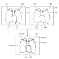
図6は胸部X線画像の位置合わせを模式的に示す模式図である。図6には過去の胸部X線画像100と、現在の胸部X線画像102とに対して剛体位置合わせを施して生成された結果画像104を示す。
<Example of alignment of chest X-ray image>
FIG. 6 is a schematic diagram schematically showing the alignment of the chest X-ray image. FIG. 6 shows a
図6に示した過去の胸部X線画像100は、図3に図示した第1医用画像50の一例である。図6に示した現在の胸部X線画像102は、図3に図示した第2医用画像51の一例である。
The past
過去の胸部X線画像100、及び現在の胸部X線画像102は、ランドマーク候補領域として鎖骨、胸郭、寛骨、脊椎、及び肺野が予め設定されている。ここに列挙した胸部X線画像におけるランドマーク候補領域は一例であり、ランドマーク領域の条件を満たす他の領域を追加してもよいし、上記したランドマーク領域の一部を削除してもよい。
In the past
図6に示した過去の胸部X線画像100、及び現在の胸部X線画像102は、寛骨を除く鎖骨、胸郭、脊椎、及び肺野が抽出されている。なお、図6では、図示の都合上、脊椎、及び肺野の図示を省略する。図7も同様である。
In the past
過去の胸部X線画像100に付した符号110、及び現在の胸部X線画像102に付した符号120は鎖骨を表す。過去の胸部X線画像100に付した符号112、及び現在の胸部X線画像102に付した符号122は胸郭を表す。
図6に示した過去の胸部X線画像100の鎖骨110、及び胸郭112と、現在の胸部X線画像102の鎖骨120、及び胸郭122は、ランドマーク領域として選択される。過去の胸部X線画像100と現在の胸部X線画像102とは、選択されたランドマーク領域を基準として位置合わせが行われる。
The
図6に示した過去の胸部X線画像100は注目領域として心臓114が選択される。また、現在の胸部X線画像102は注目領域として心臓124が選択される。結果画像104は、過去の胸部X線画像100と現在の胸部X線画像102とを重ね合わせて生成される。結果画像104は、過去の胸部X線画像100における心臓114と、現在の胸部X線画像102における心臓124との比較等の解析が可能である。
In the past
図6には、複数のランドマーク領域を用いて位置合わせを行う場合を例示した。かかる場合は、過去の胸部X線画像100の鎖骨110と、現在の胸部X線画像102の鎖骨120との位置が一致しないことがあり得る。過去の胸部X線画像100の胸郭112と、現在の胸部X線画像102の胸郭122との位置も同様である。
FIG. 6 illustrates a case where alignment is performed using a plurality of landmark areas. In such a case, the positions of the
そこで、本実施形態に示した画像処理では、過去の胸部X線画像100と現在の胸部X線画像102との誤差が最小となる位置合わせが行われる。誤差が最小となる位置合わせは既述のとおりであり、ここでの説明は省略する。
Therefore, in the image processing shown in the present embodiment, the alignment is performed so that the error between the past
〈胸部X線画像の位置合わせの他の例〉
図7は胸部X線画像の位置合わせの他の例を示す模式図である。図7に示した結果画像104Aは注目領域の位置合わせ結果が表示される一方、ランドマーク領域等の注目領域以外の領域が非表示とされる。
<Other examples of chest X-ray image alignment>
FIG. 7 is a schematic diagram showing another example of alignment of a chest X-ray image. In the
図7では、結果画像104Aにおいて表示させる心臓114は実線を用いて図示し、心臓124は点線を用いて図示する。また、二点鎖線を用いて非表示の領域を図示する。結果画像104Aにおける非表示の領域は、過去の胸部X線画像100における鎖骨110、及び胸郭112、並びに現在の胸部X線画像102における鎖骨120、及び胸郭122である。
In FIG. 7, the
図8は表示選択画面の構成例を示す説明図である。図8に示した表示選択画面140は、図3に示した表示装置24に表示される。図3に示した入力装置26を操作者が操作して、図8に示した表示選択画面140に表示された第1選択ボタン142、又は第2選択ボタン144を選択し、オーケーボタン146を押す。
FIG. 8 is an explanatory diagram showing a configuration example of a display selection screen. The
図4に示した位置合わせ部58は、表示形態の選択情報を受信する。位置合わせ部58は、表示形態の選択情報に応じて、結果画像104の全体を表示させる結果画像信号を表示制御部44へ送信するか、又は注目領域のみを表示させる結果画像信号を表示制御部44へ送信する。
The
本実施形態に示した表示装置24、及び入力装置26は、結果画像104の表示形態の選択を行うGUI(Graphical User Interface)として機能する。また、表示装置24、及び入力装置26は、表示選択部59の構成要素の一例に相当する。
The
〈頭部CT画像の位置合わせの例〉
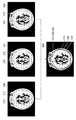
次に、医用画像の位置合わせの具体例として、頭部CT画像の位置合わせの例を説明する。図9は頭部CT画像の位置合わせの他の例を示す模式図である。図9には、過去の第1頭部CT画像200、過去の第2頭部CT画像202、及び現在の頭部CT画像204から成る3つの医用画像の位置合わせを行い、結果画像206を生成する例を示す。結果画像206を用いて、注目領域として選択された脳の経時変化の比較等の解析が可能である。符号210、符号220、及び符号230は、いずれも脳を示す。
<Example of alignment of head CT image>
Next, as a specific example of the alignment of the medical image, an example of the alignment of the head CT image will be described. FIG. 9 is a schematic diagram showing another example of alignment of the head CT image. In FIG. 9, three medical images consisting of a past first
図9に示した過去の第1頭部CT画像200、過去の第2頭部CT画像202、及び現在の頭部CT画像204は同一のスライス位置が適用される。ここでいう同一は、完全な同一に限定されず、同一とみなし得る実質的な同一であってもよい。図10、及び図11に示した頭部CT画像も同様である。
The same slice position is applied to the past first
頭部CT画像の位置合わせでは、ランドマーク候補領域として、頭蓋骨、眼球、頬骨、頚椎、及び脳槽領域が予め設定されている。なお、ここに列挙した頭部CT画像におけるランドマーク候補領域は例示であって、顎骨等のランドマーク領域の条件を満たす他の領域を追加してもよい。また、上記したランドマーク候補領域の一部を削除してもよい。 In the alignment of the head CT image, the skull, eyeball, cheekbone, cervical spine, and cistern region are preset as landmark candidate regions. The landmark candidate regions in the head CT images listed here are examples, and other regions that satisfy the conditions of the landmark regions such as the jawbone may be added. In addition, a part of the above-mentioned landmark candidate area may be deleted.
図9に示した過去の第1頭部CT画像200、過去の第2頭部CT画像202、及び現在の頭部CT画像204は、上記したランドマーク候補領域のうち頭蓋骨が抽出され、頭蓋骨がランドマーク領域として選択される。符号212、符号222、及び符号232はいずれも頭蓋骨を示す。
In the past first
図9に示した頭部CT画像の位置合わせの例は、上記した複数のランドマーク候補領域の中から1つのランドマーク候補領域が抽出され、抽出されたランドマーク候補領域をランドマーク領域として選択する例である。なお、図9に示した頭部CT画像とは、図9に示した過去の第1頭部CT画像200、過去の第2頭部CT画像202、及び現在の頭部CT画像204の総称である。図10に示した頭部CT画像、及び図11に示した頭部CT画像も同様である。
In the example of alignment of the head CT image shown in FIG. 9, one landmark candidate area is extracted from the above-mentioned plurality of landmark candidate areas, and the extracted landmark candidate area is selected as the landmark area. It is an example to do. The head CT image shown in FIG. 9 is a general term for the past first
図10は頭部CT画像の位置合わせの他の例を示す模式図であり、上記した複数のランドマーク候補領域の中から2つのランドマーク候補領域が抽出され、抽出されたランドマーク候補領域をランドマーク領域として選択する例である。 FIG. 10 is a schematic diagram showing another example of alignment of the head CT image, in which two landmark candidate areas are extracted from the above-mentioned plurality of landmark candidate areas, and the extracted landmark candidate areas are used. This is an example of selecting as a landmark area.
すなわち、過去の第1頭部CT画像200A、過去の第2頭部CT画像202A、及び現在の頭部CT画像204Aから頭蓋骨、及び眼球が抽出され、頭蓋骨、及び眼球をランドマーク領域として選択される。図10に示した符号214、符号224、及び符号234はいずれも眼球を示す。
That is, the skull and the eyeball are extracted from the past first
図10に示した過去の第1頭部CT画像200Aは、図9に示した過去の第1頭部CT画像200と比較して、スライス位置が顎の側となっている。図10に示した過去の第2頭部CT画像202A、及び現在の頭部CT画像204Aも同様である。
The past first
図10に示した過去の第1頭部CT画像200A、過去の第2頭部CT画像202A、及び現在の頭部CT画像204Aの位置合わせの結果、結果画像206Aが生成される。
As a result of the alignment of the past first
図11は頭部CT画像の位置合わせの他の例を示す模式図であり、ランドマーク領域として頭蓋骨、及び頬骨を選択した例の模式図である。図11には左右の頬骨をランドマーク領域として選択する例を示したが、左の頬骨、又は右の頬骨のいずれかをランドマーク領域として選択してもよい。図7に示した鎖骨、及び胸郭、並びに図9に示した眼球も同様である。 FIG. 11 is a schematic diagram showing another example of alignment of the head CT image, and is a schematic diagram of an example in which the skull and cheekbone are selected as landmark regions. Although FIG. 11 shows an example in which the left and right cheekbones are selected as the landmark area, either the left cheekbone or the right cheekbone may be selected as the landmark area. The same applies to the clavicle and thorax shown in FIG. 7, and the eyeball shown in FIG.
図11に示した過去の第1頭部CT画像200Bは、図10に示した過去の第1頭部CT画像200Aと比較して、スライス位置が顎の側となっている。図11に示した過去の第2頭部CT画像202B、及び現在の頭部CT画像204Bも同様である。
The past first
図11に示した過去の第1頭部CT画像200B、過去の第2頭部CT画像202B、及び現在の頭部CT画像204Bの剛体位置合わせの結果、結果画像206Bが生成される。図11に示した符号216、符号226、及び符号236はいずれも眼球を示す。
As a result of the rigid body alignment of the past first
図10、及び図11に示した頭部CT画像の位置合わせの例は、複数のランドマーク候補領域の中から複数のランドマーク領域を選択する例である。図10、及び図11には複数のランドマーク領域を選択する例として2つのランドマーク領域を選択する例を示したが、ランドマーク領域の数は3つ以上でもよい。 The example of alignment of the head CT image shown in FIGS. 10 and 11 is an example of selecting a plurality of landmark areas from a plurality of landmark candidate areas. 10 and 11 show an example of selecting two landmark areas as an example of selecting a plurality of landmark areas, but the number of landmark areas may be three or more.
結果画像の表示形態は、胸部X画像の例と同様に、結果画像の全体を表示してもよいし、注目領域のみを表示してもよい。結果画像の表示形態の選択は、図8に示した表示選択画面140と同様の選択画面を用いて選択することが可能である。なお、結果画像は、図9に示した結果画像206、図10に示した結果画像206A、及び図11に示した結果画像206Bの総称である。
As the display form of the result image, the entire result image may be displayed or only the region of interest may be displayed, as in the case of the chest X image. The display form of the result image can be selected by using the same selection screen as the
図12は処理対象画像選択画面の構成例を示す説明図である。図12に示した処理対象画像選択画面240は、過去の第1頭部CT画像200、過去の第2頭部CT画像202、及び現在の頭部CT画像204のうち、過去の第2頭部CT画像202、及び現在の頭部CT画像204が位置合わせの処理対象として選択された場合を示す。オーケーボタン242を押下すると、処理対象の選択が確定する。
FIG. 12 is an explanatory diagram showing a configuration example of a processing target image selection screen. The processing target
すなわち、図12に示した例では、現在の頭部CT画像204と、過去の頭部CT画像のうち最新の過去の第2頭部CT画像202とが位置合わせの処理対象として選択される。図12に示した処理対象画像選択画面240は、過去の第1頭部CT画像200、過去の第2頭部CT画像202、及び現在の頭部CT画像204の下側には、それぞれの撮像日が表示されている。このように、処理対象画像選択画面240は、各医用画像の付帯情報を表示してもよい。なお、図12に図示した日付は任意の日付である。
That is, in the example shown in FIG. 12, the current
図12に示した処理対象画像選択画面240において、過去の第1頭部CT画像200、と現在の頭部CT画像204との選択、及び過去の第1頭部CT画像200と、過去の第2頭部CT画像202と、現在の頭部CT画像204との選択も可能である。
On the processing target
本実施形態では、胸部X線画像、及び頭部CT画像等の二次元の医用画像の位置合わせを例示したが、本実施形態に係る画像処理は3次元の医用画像にも適用可能である。 In the present embodiment, the alignment of a two-dimensional medical image such as a chest X-ray image and a head CT image is exemplified, but the image processing according to the present embodiment can also be applied to a three-dimensional medical image.
[第1実施形態に係る画像処理装置、及び方法の作用効果]
第1実施形態に係る画像処理装置、及び方法によれば、以下の作用効果を得ることが可能である。
[Action and effect of the image processing apparatus and method according to the first embodiment]
According to the image processing apparatus and method according to the first embodiment, the following effects can be obtained.
〔1〕
位置合わせ対象の医用画像について、複数のランドマーク候補領域が予め規定される。位置合わせ対象の複数の医用画像から注目領域を含む複数の領域が抽出される。複数のランドマーク候補領域のうち、位置合わせ対象の複数の医用画像の全てにおいて抽出された領域であり、注目領域以外の領域の中から1つ以上のランドマーク領域が選択される。選択されたランドマーク領域を位置合わせの基準として、位置合わせ対象の複数の医用画像の位置合わせを行う。これにより、位置合わせ対象の複数の医用画像についての高精度の位置合わせが可能である。
[1]
A plurality of landmark candidate areas are defined in advance for the medical image to be aligned. A plurality of regions including a region of interest are extracted from a plurality of medical images to be aligned. Among the plurality of landmark candidate regions, the regions are extracted in all of the plurality of medical images to be aligned, and one or more landmark regions are selected from the regions other than the region of interest. Aligning a plurality of medical images to be aligned is performed using the selected landmark area as a reference for alignment. This enables highly accurate alignment of a plurality of medical images to be aligned.
〔2〕
位置合わせ対象の複数の医用画像から抽出された領域の中から、注目領域が選択される。これにより、複数の医用画像から抽出された領域の中から、1つ以上の任意の領域を注目領域とすることが可能である。
[2]
The region of interest is selected from the regions extracted from the plurality of medical images to be aligned. Thereby, it is possible to set one or more arbitrary regions as the region of interest from the regions extracted from the plurality of medical images.
〔3〕
複数の医用画像を重ね合わせた結果画像206を生成する。これにより、複数の医用画像の比較等の解析が可能となる。
[3]
〔4〕
機械学習の結果を用いて、医用画像から領域抽出が行われる。これにより、高精度の領域抽出が可能である。また、領域ごとの抽出結果を用いて機械学習が行われる。これにより、高精度の領域抽出が可能である。
[4]
Region extraction is performed from the medical image using the result of machine learning. This enables highly accurate region extraction. In addition, machine learning is performed using the extraction results for each region. This enables highly accurate region extraction.
〔5〕
ランドマーク領域の候補とされるランドマーク候補領域が予め設定される。ランドマーク候補領域のうち、複数の医用画像から抽出された領域の中からランドマーク領域が選択される。これにより、複数の医用画像に応じたランドマーク候補領域の設定が可能である。また、ランドマーク候補領域からランドマーク領域の選択が可能である。
[5]
A landmark candidate area that is a candidate for the landmark area is preset. Among the landmark candidate areas, the landmark area is selected from the areas extracted from a plurality of medical images. This makes it possible to set landmark candidate areas according to a plurality of medical images. In addition, the landmark area can be selected from the landmark candidate area.
〔6〕
複数のランドマークを用いて、誤差が最小となる位置合わせが行われる。これにより、複数の医用画像の高精度の位置合わせが可能である。
[6]
Alignment with minimal error is performed using multiple landmarks. This enables highly accurate alignment of a plurality of medical images.
〔7〕
複数の医用画像は、同一の患者における、同一の被検体について、異なる時期に生成された医用画像が適用される。これにより、同一の患者における、同一の被検体について、経時変化観察等の解析が可能である。
[7]
For the plurality of medical images, medical images generated at different times for the same subject in the same patient are applied. This makes it possible to perform analysis such as observation of changes over time for the same subject in the same patient.
〔8〕
位置合わせ部58は、結果画像206を表す結果画像信号を表示制御部44へ送信する。これにより、表示装置24を用いて結果画像206を表示し得る。画像処理部42は、結果画像206の全体を表示させるか、又は注目領域のみを表示させるかを選択する表示選択部59を備える。これにより、結果画像206の全体表示、又は注目領域のみの表示の選択が可能である。
[8]
The
[第2実施形態に係る画像処理装置、及び方法]
次に、第2実施形態に係る画像処理装置、及び方法について説明する。
[Image processing device and method according to the second embodiment]
Next, the image processing apparatus and the method according to the second embodiment will be described.
〔画像処理装置の構成例〕
図13は第2実施形態に係る画像処理部の機能を示すブロック図である。第2実施形態に係る画像処理装置は、図13に示した画像処理部42Aを備える、画像処理部42Aは、優先度設定部250を備える。
[Configuration example of image processing device]
FIG. 13 is a block diagram showing a function of the image processing unit according to the second embodiment. The image processing apparatus according to the second embodiment includes the
優先度設定部250は、ランドマーク候補領域に優先度を設定する。ランドマーク領域選択部56は、ランドマーク候補領域に設定された優先度に基づいて、ランドマーク領域を選択する。
The
図6に示した過去の胸部X線画像100、及び現在の胸部X線画像102は、ランドマーク候補領域として鎖骨、胸郭、寛骨、脊椎、及び肺野が設定される。これらのランドマーク候補領域の優先度の設定例として、最も高い優先度が鎖骨に設定され、最も低い優先度が肺野に設定され、かつ鎖骨、胸郭、寛骨、脊椎、及び肺野の順に優先度が低くなる設定例が挙げられる。
In the past
図6に示した過去の胸部X線画像100、及び現在の胸部X線画像102は、寛骨以外のランドマーク候補領域が抽出される。過去の胸部X線画像100、及び現在の胸部X線画像102から抽出されたランドマーク候補領域のうち、優先度が高い鎖骨、及び胸郭がランドマークとして選択される。
In the past
図9から図11に示した頭部CT画像は、頭蓋骨、眼球、頬骨、頚椎、及び脳槽領域がランドマーク候補領域として設定される。これらのランドマーク候補領域の優先度の設定例として、最も高い優先度が頭蓋骨に設定され、最も低い優先度が脳槽領域に設定され、かつ頭蓋骨、眼球、頬骨、頚椎、及び脳槽領域の順に優先度が低くなる設定例が挙げられる。 In the head CT images shown in FIGS. 9 to 11, the skull, eyeball, cheekbone, cervical spine, and cistern region are set as landmark candidate regions. As an example of setting the priority of these landmark candidate regions, the highest priority is set to the skull, the lowest priority is set to the cistern region, and the skull, eyeball, cheekbone, cervical spine, and cistern region. An example of setting in which the priority becomes lower in order is given.
図10に示した例では、優先順位が最も高い頭蓋骨、及び優先順位が二番目に高い眼球がランドマークとして選択される。変化が相対的に少ないランドマーク候補領域は優先度が相対的に高く設定される。一方、変化が相対的に多いランドマーク候補領域は優先度が相対的に低く設定される。 In the example shown in FIG. 10, the skull with the highest priority and the eyeball with the second highest priority are selected as landmarks. Landmark candidate areas with relatively little change are set with relatively high priority. On the other hand, the landmark candidate area where the change is relatively large is set to have a relatively low priority.
図13に示した優先度設定部250は、入力装置26を用いて入力された優先度設定情報を表す信号に基づいて、複数のランドマーク候補領域に対して優先度を設定することが可能である。
The
図14は優先度設定画面の構成例を示す説明図である。図14に示した優先度設定画面260は、最も優先度が高い領域を指定する第1設定タブ262、二番目に優先度が高い領域を指定する第2設定タブ264、三番目に優先度が高い領域を指定する第3設定タブ266、四番目に優先度が高い領域を指定する第4設定タブ268、及び最も優先度が低い領域を指定する第5設定タブ270が表示される。
FIG. 14 is an explanatory diagram showing a configuration example of the priority setting screen. Priority setting screen shown in FIG. 14 260
第1設定タブ262は、文字入力を適用してもよいし、プルダウンメニューを適用してもよい。第2設定タブ264、第3設定タブ266、第4設定タブ268、及び第5設定タブ270も同様である。
The
第1設定タブ262から第5設定タブ270に領域名を入力し、オーケーボタン272を押下すると優先度の設定が確定する。なお、第2設定タブ264から第5設定タブ270までのいずれかを未入力としてもよい。
Enter the area name in the
図14には5つの優先度設定タブを備える優先度設定画面260を図示したが、優先度設定タブの数は医用画像の種類、注目領域等に応じて適宜変更してもよい。
Although FIG. 14 shows a
〔第2実施形態に係る画像処理方法の手順〕
図15は第2実施形態に係る画像処理方法の手順の流れを示すフローチャートである。図15に示したフローチャートは、図5に示したフローチャートの注目領域選択工程S14と、ランドマーク領域選択工程S16との間に、優先度設定工程S15が追加される。
[Procedure of image processing method according to the second embodiment]
FIG. 15 is a flowchart showing the flow of the procedure of the image processing method according to the second embodiment. In the flowchart shown in FIG. 15, a priority setting step S15 is added between the attention area selection step S14 and the landmark area selection step S16 in the flowchart shown in FIG.
優先度設定工程S15では、図13に示した優先度設定部250は、予め設定されているランドマーク候補領域に対して優先度を設定する。優先度設定工程S15の後に、ランドマーク領域選択工程S16へ進む。
In the priority setting step S15, the
ランドマーク領域選択工程S16では、図13に示したランドマーク領域選択部56は、優先度設定工程S15において、ランドマーク候補領域に対して設定された優先度の高い順にランドマーク領域を選択する。他の工程は、図5に示した各工程と同一であり、ここでの説明を省略する。
In the landmark area selection step S16, the landmark
[第2実施形態に係る画像処理装置、及び方法の作用効果]
第2実施形態に係る画像処理装置、及び方法によれば、以下の作用効果を得ることが可能である。
[Action and effect of the image processing apparatus and method according to the second embodiment]
According to the image processing apparatus and method according to the second embodiment, the following effects can be obtained.
〔1〕
ランドマーク候補領域に対して優先度を設定する優先度設定部250を備える。これにより、優先度に基づくランドマーク領域の選択が可能である。
[1]
A
〔2〕
表示装置24に優先度設定画面260を表示させる。優先度設定画面260は入力装置を用いて領域の情報を入力可能な設定タブが表示される。これにより、入力装置を用いて、ランドマーク候補領域に対して優先度を設定することが可能である。
[2]
Display the
[ネットワークシステムへの適用例]
図16はネットワークシステムが適用される情報処理システムの構成例を示すブロック図である。図16に示した情報処理システム300は、サーバ装置302、及び医療機関304に具備される端末装置306を備える。サーバ装置302と端末装置306とはネットワーク308を介して通信可能に接続される。
[Application example to network system]
FIG. 16 is a block diagram showing a configuration example of an information processing system to which a network system is applied. The
医療機関304は、図16に図示した第1医療機関304A、第2医療機関304B、及び第3医療機関304Cの総称である。また、端末装置306は、図16に図示した第1医療機関304Aに具備される端末装置306A、第2医療機関304Bに具備される端末装置306B、及び第3医療機関304Cに具備される端末装置306Cの総称である。
The medical institution 304 is a general term for the first
端末装置306は、図1から図4を用いて説明した画像処理装置12と同様の構成、及び機能を有している。ここでは、端末装置306の構成、及び機能等の説明は省略する。端末装置306は、医療機関304が備えるモダリティと通信可能に接続されてもよい。図16ではモダリティの図示を省略する。モダリティは図1に符号14を付して図示する。
The terminal device 306 has the same configuration and function as the
サーバ装置302は、図1に示した画像データベース16等の医用画像データベース310を備える。サーバ装置302は、端末装置306との間で医用画像を高速で送受信可能に構成される。図16に示したDBはData Baseの省略語である。
The
医用画像データベース310は、ネットワーク308に接続されるNAS(Network Attached Storage)を適用し得る。医用画像データベース310は、SAN(Storage Area Network)に接続されたディスク装置を適用し得る。
The
サーバ装置302は第2機械学習器312を備える。第2機械学習器312は、図4に示した機械学習器53と同様に、コンボリューションニューラルネットワークを適用可能である。
The
第2機械学習器312は、図4、及び図13に示した機械学習器53の機能を備えることが可能である。サーバ装置302に具備される第2機械学習器312は、機械学習器53を更新する機械学習器更新部として機能し得る。
The second
すなわち、第2機械学習器312は、図4、及び図13に示した抽出部52の抽出結果を用いた機械学習を行い、抽出部52に適用される抽出規則を更新して、機械学習器53を更新してもよい。
That is, the second
ネットワーク308は、公衆回線網を適用してもよいし、専用回線網を適用してもよい。ネットワーク308は、光ファイバー等の高速通信ケーブルが適用される。ネットワーク308はDICOM規格に準拠した通信プロトコルを適用可能である。
The
[コンピュータを画像処理装置として機能させるプログラムへの適用例]
上述した画像処理方法は、コンピュータを用いて、画像処理装置における各部に対応する機能、及び画像処理方法における各工程に対応する機能を実現させるプログラムとして構成可能である。
[Example of application to a program that makes a computer function as an image processing device]
The above-mentioned image processing method can be configured as a program that realizes a function corresponding to each part in the image processing apparatus and a function corresponding to each process in the image processing method by using a computer.
例えば、第1医用画像、及び第2医用画像を取得する画像取得機能、第1医用画像、及び第2医用画像のそれぞれから、注目領域を含む複数の領域を抽出する抽出機能、第1医用画像の複数の領域、及び第2医用画像の複数の領域のうち、第1医用画像と第2医用画像とに共通する領域であり、注目領域と異なる特定の領域を、第1医用画像と第2医用画像との位置合わせの基準となるランドマーク領域として選択するランドマーク領域選択機能、及びランドマーク領域を位置合わせの基準として、第1医用画像と第2医用画像との位置合わせを行い、第1医用画像と第2医用画像とを重ね合わせた結果画像を生成する位置合わせ機能を実現させるプログラムを構成し得る。 For example, an image acquisition function for acquiring a first medical image and a second medical image, an extraction function for extracting a plurality of regions including a region of interest from each of the first medical image and the second medical image, and a first medical image. Of the plurality of regions of the above and the plurality of regions of the second medical image, a specific region that is common to the first medical image and the second medical image and is different from the region of interest is defined as the first medical image and the second. A landmark area selection function that selects as a landmark area that serves as a reference for alignment with a medical image, and an alignment between a first medical image and a second medical image using the landmark area as a reference for alignment are performed. It is possible to construct a program that realizes an alignment function that generates an image as a result of superimposing one medical image and a second medical image.
上述した画像処理機能をコンピュータに実現させるプログラムを、有体物である非一時的な情報記憶媒体である、コンピュータが読取可能な情報記憶媒体に記憶し、情報記憶媒体を通じてプログラムを提供することが可能である。 It is possible to store the program that realizes the above-mentioned image processing function in a computer in a computer-readable information storage medium, which is a tangible non-temporary information storage medium, and provide the program through the information storage medium. be.
また、非一時的な情報記憶媒体にプログラムを記憶して提供する態様に代えて、ネットワークを介してプログラム信号を提供する態様も可能である。 Further, instead of the mode in which the program is stored and provided in the non-temporary information storage medium, the mode in which the program signal is provided via the network is also possible.
[実施形態及び変形例等の組み合わせについて]
上述した実施形態で説明した構成要素、及び変形例で説明した構成要素は、適宜組み合わせて用いることができ、また、一部の構成要素を置き換えることもできる。
[Combination of embodiments and modifications]
The components described in the above-described embodiment and the components described in the modified examples can be used in combination as appropriate, or some components can be replaced.
以上説明した本発明の実施形態は、本発明の趣旨を逸脱しない範囲で、適宜構成要件を変更、追加、削除することが可能である。本発明は以上説明した実施形態に限定されるものではなく、本発明の技術的思想内で当該分野の通常の知識を有する者により、多くの変形が可能である。 In the embodiment of the present invention described above, the constituent requirements can be appropriately changed, added, or deleted without departing from the spirit of the present invention. The present invention is not limited to the embodiments described above, and many modifications can be made by a person having ordinary knowledge in the art within the technical idea of the present invention.
10 医療情報システム
12 画像処理装置
14 モダリティ
16 画像データベース
18 ネットワーク
20 マウス
22 キーボード
24 表示装置
26 入力装置
30 制御部
32 メモリ
34 ハードディスク装置
36 通信インターフェース
38 入力コントローラ
39 ディスプレイコントローラ
40 全体制御部
41 画像取得部
42 画像処理部
42A 画像処理部
43 深層学習アルゴリズム
44 表示制御部
45 画面生成部
46 入力制御部
47 記憶部
48 画像記憶部
49 プログラム記憶部
50 第1医用画像
51 第2医用画像
52 抽出部
53 機械学習器
53A 正解データ
54 注目領域選択部
55 ランドマーク候補領域設定部
56 ランドマーク領域選択部
58 位置合わせ部
58A 誤差算出部
59 表示選択部
60 通信信号線
100 過去の胸部X線画像
102 現在の胸部X線画像
104 結果画像
104A 結果画像
110 鎖骨
112 胸郭
114 心臓
120 鎖骨
122 胸郭
124 心臓
140 表示選択画面
142 第1選択ボタン
144 第2選択ボタン
146 オーケーボタン
200 過去の第1頭部CT画像
200A 過去の第1頭部CT画像
200B 過去の第1頭部CT画像
202 過去の第2頭部CT画像
202A 過去の第2頭部CT画像
202B 過去の第2頭部CT画像
204 現在の頭部CT画像
204A 現在の頭部CT画像
204B 現在の頭部CT画像
206 結果画像
206A 結果画像
206B 結果画像
210 脳
212 頭蓋骨
214 眼球
216 頬骨
220 脳
222 頭蓋骨
224 眼球
226 頬骨
230 脳
232 頭蓋骨
234 眼球
236 頬骨
240 処理対象画像選択画面
242 オーケーボタン
250 優先度設定部
260 優先度設定画面
262 第1設定タブ
264 第2設定タブ
266 第3設定タブ
268 第4設定タブ
270 第5設定タブ
272 オーケーボタン
300 情報処理システム
302 サーバ装置
304 医療機関
304A 第1医療機関
304B 第2医療機関
304C 第3医療機関
306 端末装置
306A 端末装置
306B 端末装置
306C 端末装置
308 ネットワーク
310 医用画像データベース
312 第2機械学習器
S10からS26 画像処理方法の各工程
10 Medical information system 12 Image processing device 14 Modality 16 Image database 18 Network 20 Mouse 22 Keyboard 24 Display device 26 Input device 30 Control unit 32 Memory 34 Hard disk device 36 Communication interface 38 Input controller 39 Display controller 40 Overall control unit 41 Image acquisition unit 42 Image processing unit 42A Image processing unit 43 Deep learning algorithm 44 Display control unit 45 Screen generation unit 46 Input control unit 47 Storage unit 48 Image storage unit 49 Program storage unit 50 First medical image 51 Second medical image 52 Extraction unit 53 Machine Learner 53A Correct answer data 54 Interest area selection unit 55 Landmark candidate area setting unit 56 Landmark area selection unit 58 Alignment unit 58A Error calculation unit 59 Display selection unit 60 Communication signal line 100 Past chest X-ray image 102 Current chest X-ray image 104 Result image 104A Result image 110 Cirrhosis 112 Chest 114 Heart 120 Cirrhosis 122 Chest 124 Heart 140 Display selection screen 142 First selection button 144 Second selection button 146 OK button 200 Past first head CT image 200A Past 1st Head CT Image 200B Past 1st Head CT Image 202 Past 2nd Head CT Image 202A Past 2nd Head CT Image 202B Past 2nd Head CT Image 204 Current Head CT Image 204A Current head CT image 204B Current head CT image 206 Result image 206A Result image 206B Result image 210 Brain 212 Skeleton 214 Eyeball 216 Cheekbone 220 Brain 222 Skeleton 224 Eyeball 226 Cheekbone 230 Brain 232 Skeleton 234 Eyeball 236 Cheekbone 240 Processing target image Selection screen 242 OK button 250 Priority setting unit 260 Priority setting screen 262 1st setting tab 264 2nd setting tab 266 3rd setting tab 268 4th setting tab 270 5th setting tab 272 OK button 300 Information processing system 302 Server device 304 Medical institution 304A 1st medical institution 304B 2nd medical institution 304C 3rd medical institution 306 Terminal device 306A Terminal device 306B Terminal device 306C Terminal device 308 Network 310 Medical image database 312 2nd machine learner S10 to S26 Each of the image processing methods Process
Claims (27)
前記第1医用画像、及び前記第2医用画像のそれぞれから、前記注目領域を含む複数の領域を抽出する抽出部と、
前記第1医用画像の前記複数の領域、及び前記第2医用画像の前記複数の領域のうち、前記第1医用画像と前記第2医用画像とに共通する領域であり、前記注目領域と臓器又は組織が異なる特定の領域を、前記第1医用画像と前記第2医用画像との位置合わせの基準となるランドマーク領域として選択するランドマーク領域選択部と、
前記ランドマーク領域を位置合わせの基準として、前記第1医用画像と前記第2医用画像との剛体レジストレーション、又は線形レジストレーションを行い、前記第1医用画像と前記第2医用画像とを重ね合わせた結果画像を生成する位置合わせ部と、
を備え、
前記抽出部は、前記医用画像と前記領域の抽出結果との組、又は前記医用画像と前記ランドマーク領域の選択結果との組を正解データとして学習した学習結果を用いて、前記領域の抽出を行う画像処理装置。 An image acquisition unit that acquires a first medical image including a region of interest to be compared, and a plurality of medical images including a second medical image, and an image acquisition unit.
An extraction unit that extracts a plurality of regions including the region of interest from each of the first medical image and the second medical image.
Of the plurality of regions of the first medical image and the plurality of regions of the second medical image, the regions common to the first medical image and the second medical image, and the region of interest and an organ or A landmark area selection unit that selects a specific area having a different tissue as a landmark area that serves as a reference for alignment between the first medical image and the second medical image.
Rigid registration or linear registration of the first medical image and the second medical image is performed using the landmark region as a reference for alignment, and the first medical image and the second medical image are superposed. The alignment part that generates the resulting image and
Equipped with
The extraction unit extracts the region by using the learning result of learning the pair of the medical image and the extraction result of the region or the pair of the medical image and the selection result of the landmark region as correct data. Image processing equipment to perform.
前記第1医用画像、及び前記第2医用画像のそれぞれから、前記注目領域を含む複数の領域を抽出する抽出部と、
前記第1医用画像の前記複数の領域、及び前記第2医用画像の前記複数の領域のうち、前記第1医用画像と前記第2医用画像とに共通する領域であり、前記注目領域と臓器又は組織が異なる特定の領域を、前記第1医用画像と前記第2医用画像との位置合わせの基準となるランドマーク領域として選択するランドマーク領域選択部と、
前記ランドマーク領域を位置合わせの基準として、前記第1医用画像と前記第2医用画像との剛体レジストレーション、又は線形レジストレーションを行い、前記第1医用画像と前記第2医用画像とを重ね合わせた結果画像を生成する位置合わせ部と、
を備え、
前記抽出部は、前記医用画像と前記領域ごとの抽出結果との組、又は前記医用画像と前記ランドマーク領域の選択結果との組を正解データとして、前記領域ごとに学習した学習結果を用いて、前記領域の抽出を行う画像処理装置。 An image acquisition unit that acquires a first medical image including a region of interest to be compared, and a plurality of medical images including a second medical image, and an image acquisition unit.
An extraction unit that extracts a plurality of regions including the region of interest from each of the first medical image and the second medical image.
Of the plurality of regions of the first medical image and the plurality of regions of the second medical image, the regions common to the first medical image and the second medical image, and the region of interest and an organ or A landmark area selection unit that selects a specific area having a different tissue as a landmark area that serves as a reference for alignment between the first medical image and the second medical image.
Rigid registration or linear registration of the first medical image and the second medical image is performed using the landmark region as a reference for alignment, and the first medical image and the second medical image are superposed. The alignment part that generates the resulting image and
Equipped with
The extraction unit uses the learning result learned for each area using the set of the medical image and the extraction result for each area or the set of the medical image and the selection result of the landmark area as correct answer data. , An image processing device that extracts the area.
前記第1医用画像、及び前記第2医用画像のそれぞれから、前記注目領域を含む複数の領域を抽出する抽出部と、
前記第1医用画像の前記複数の領域、及び前記第2医用画像の前記複数の領域のうち、前記第1医用画像と前記第2医用画像とに共通する領域であり、前記注目領域と異なる特定の領域を、前記第1医用画像と前記第2医用画像との位置合わせの基準となるランドマーク領域として選択するランドマーク領域選択部と、
前記ランドマーク領域を位置合わせの基準として、前記第1医用画像と前記第2医用画像との剛体レジストレーション、又は線形レジストレーションを行い、前記第1医用画像と前記第2医用画像とを重ね合わせた結果画像を生成する位置合わせ部と、
前記第1医用画像、及び前記第2医用画像について、前記ランドマーク領域の候補とされるランドマーク候補領域を設定するランドマーク候補領域設定部と、
前記ランドマーク候補領域に優先度を設定する優先度設定部と、
を備えた画像処理装置。 An image acquisition unit that acquires a first medical image including a region of interest to be compared, and a plurality of medical images including a second medical image, and an image acquisition unit.
An extraction unit that extracts a plurality of regions including the region of interest from each of the first medical image and the second medical image.
Of the plurality of regions of the first medical image and the plurality of regions of the second medical image, the regions common to the first medical image and the second medical image, and are different from the attention region. A landmark area selection unit that selects the area of the above as a landmark area that serves as a reference for alignment between the first medical image and the second medical image.
Rigid registration or linear registration of the first medical image and the second medical image is performed using the landmark region as a reference for alignment, and the first medical image and the second medical image are superposed. The alignment part that generates the resulting image and
With respect to the first medical image and the second medical image, a landmark candidate area setting unit for setting a landmark candidate area as a candidate for the landmark area, and a landmark candidate area setting unit.
A priority setting unit that sets a priority in the landmark candidate area,
Image processing device equipped with.
前記位置合わせ部は、前記ランドマーク領域選択部を用いて選択された前記複数のランドマーク領域を用いて前記結果画像を生成する際に、前記ランドマーク領域の誤差が最小となる前記第1医用画像と前記第2医用画像と位置合わせを行う請求項1から12のいずれか一項に記載の画像処理装置。 The landmark area selection unit selects a plurality of the landmark areas and selects a plurality of the landmark areas.
The alignment unit is used for the first medical use in which an error in the landmark area is minimized when the result image is generated using the plurality of landmark areas selected by the landmark area selection unit. The image processing apparatus according to any one of claims 1 to 12, which aligns an image with the second medical image.
前記第1医用画像、及び前記第2医用画像のそれぞれから、前記注目領域を含む複数の領域を抽出する抽出工程と、
前記第1医用画像の前記複数の領域、及び前記第2医用画像の前記複数の領域のうち、前記第1医用画像と前記第2医用画像とに共通する領域であり、前記注目領域と臓器又は組織が異なる特定の領域を、前記第1医用画像と前記第2医用画像との位置合わせの基準となるランドマーク領域として選択するランドマーク領域選択工程と、
前記ランドマーク領域を位置合わせの基準として、前記第1医用画像と前記第2医用画像との剛体レジストレーション、又は線形レジストレーションを行い、前記第1医用画像と前記第2医用画像とを重ね合わせた結果画像を生成する位置合わせ工程と、
を含み、
前記抽出工程は、前記医用画像と前記領域の抽出結果との組、又は前記医用画像と前記ランドマーク領域の選択結果との組を正解データとして学習した学習結果を用いて、前記領域の抽出を行う画像処理方法。 An image acquisition step of acquiring a first medical image including a region of interest to be compared and a plurality of medical images including a second medical image, and an image acquisition step.
An extraction step of extracting a plurality of regions including the region of interest from each of the first medical image and the second medical image.
Of the plurality of regions of the first medical image and the plurality of regions of the second medical image, the regions common to the first medical image and the second medical image, and the region of interest and an organ or A landmark area selection step of selecting a specific area having a different tissue as a landmark area as a reference for alignment between the first medical image and the second medical image.
Rigid registration or linear registration of the first medical image and the second medical image is performed using the landmark region as a reference for alignment, and the first medical image and the second medical image are superposed. The alignment process to generate the resulting image and
Including
In the extraction step, the region is extracted using the learning result obtained by learning the pair of the medical image and the extraction result of the region or the pair of the medical image and the selection result of the landmark region as correct data. Image processing method to be performed.
前記第1医用画像、及び前記第2医用画像のそれぞれから、前記注目領域を含む複数の領域を抽出する抽出工程と、
前記第1医用画像の前記複数の領域、及び前記第2医用画像の前記複数の領域のうち、前記第1医用画像と前記第2医用画像とに共通する領域であり、前記注目領域と臓器又は組織が異なる特定の領域を、前記第1医用画像と前記第2医用画像との位置合わせの基準となるランドマーク領域として選択するランドマーク領域選択工程と、
前記ランドマーク領域を位置合わせの基準として、前記第1医用画像と前記第2医用画像との剛体レジストレーション、又は線形レジストレーションを行い、前記第1医用画像と前記第2医用画像とを重ね合わせた結果画像を生成する位置合わせ工程と、
を含み、
前記抽出工程は、前記医用画像と前記領域ごとの抽出結果との組、又は前記医用画像と前記ランドマーク領域の選択結果との組を正解データとして、前記領域ごとに学習した学習結果を用いて、前記領域の抽出を行う画像処理方法。 An image acquisition step of acquiring a first medical image including a region of interest to be compared and a plurality of medical images including a second medical image, and an image acquisition step.
An extraction step of extracting a plurality of regions including the region of interest from each of the first medical image and the second medical image.
Of the plurality of regions of the first medical image and the plurality of regions of the second medical image, the regions common to the first medical image and the second medical image, and the region of interest and an organ or A landmark area selection step of selecting a specific area having a different tissue as a landmark area as a reference for alignment between the first medical image and the second medical image.
Rigid registration or linear registration of the first medical image and the second medical image is performed using the landmark region as a reference for alignment, and the first medical image and the second medical image are superposed. The alignment process to generate the resulting image and
Including
In the extraction step, the pair of the medical image and the extraction result for each region or the pair of the medical image and the selection result of the landmark region is used as correct answer data, and the learning result learned for each region is used. , An image processing method for extracting the area.
前記医用画像と前記ランドマーク領域の選択結果との組を正解データとして学習した学習結果を用いて、前記領域の抽出を行う請求項18又は19に記載の画像処理方法。The image processing method according to claim 18 or 19, wherein the area is extracted by using the learning result obtained by learning the set of the medical image and the selection result of the landmark area as correct answer data.
前記第1医用画像、及び前記第2医用画像のそれぞれから、前記注目領域を含む複数の領域を抽出する抽出工程と、
前記第1医用画像の前記複数の領域、及び前記第2医用画像の前記複数の領域のうち、前記第1医用画像と前記第2医用画像とに共通する領域であり、前記注目領域と異なる特定の領域を、前記第1医用画像と前記第2医用画像との位置合わせの基準となるランドマーク領域として選択するランドマーク領域選択工程と、
前記ランドマーク領域を位置合わせの基準として、前記第1医用画像と前記第2医用画像との剛体レジストレーション、又は線形レジストレーションを行い、前記第1医用画像と前記第2医用画像とを重ね合わせた結果画像を生成する位置合わせ工程と、
前記第1医用画像、及び前記第2医用画像について、前記ランドマーク領域の候補とされるランドマーク候補領域を設定するランドマーク候補領域設定工程と、
前記ランドマーク候補領域に優先度を設定する優先度設定工程と、
を含む画像処理方法。 An image acquisition step of acquiring a first medical image including a region of interest to be compared and a plurality of medical images including a second medical image, and an image acquisition step.
An extraction step of extracting a plurality of regions including the region of interest from each of the first medical image and the second medical image.
Of the plurality of regions of the first medical image and the plurality of regions of the second medical image, the regions common to the first medical image and the second medical image, and are different from the attention region. A landmark area selection step of selecting the area of the above as a landmark area as a reference for alignment between the first medical image and the second medical image.
Rigid registration or linear registration of the first medical image and the second medical image is performed using the landmark region as a reference for alignment, and the first medical image and the second medical image are superposed. The alignment process to generate the resulting image and
With respect to the first medical image and the second medical image, a landmark candidate area setting step for setting a landmark candidate area as a candidate for the landmark area, and a landmark candidate area setting step.
The priority setting process for setting the priority in the landmark candidate area and
Image processing methods including.
比較する注目領域をそれぞれに含む第1医用画像、及び第2医用画像を含む複数の医用画像を取得する画像取得機能、
前記第1医用画像、及び前記第2医用画像のそれぞれから、前記注目領域を含む複数の領域を抽出する抽出機能、
前記第1医用画像の前記複数の領域、及び前記第2医用画像の前記複数の領域のうち、前記第1医用画像と前記第2医用画像とに共通する領域であり、前記注目領域と臓器又は組織が異なる特定の領域を、前記第1医用画像と前記第2医用画像との位置合わせの基準となるランドマーク領域として選択するランドマーク領域選択機能、及び
前記ランドマーク領域を位置合わせの基準として、前記第1医用画像と前記第2医用画像との剛体レジストレーション、又は線形レジストレーションを行い、前記第1医用画像と前記第2医用画像とを重ね合わせた結果画像を生成する位置合わせ機能を実現させるプログラムであり、
前記抽出機能は、前記医用画像と前記領域の抽出結果との組、又は前記医用画像と前記ランドマーク領域の選択結果との組を正解データとして学習した学習結果を用いて、前記領域の抽出を行うプログラム。 On the computer
An image acquisition function for acquiring a first medical image including a region of interest to be compared and a plurality of medical images including a second medical image.
An extraction function for extracting a plurality of regions including the region of interest from each of the first medical image and the second medical image.
Of the plurality of regions of the first medical image and the plurality of regions of the second medical image, the regions common to the first medical image and the second medical image, and the region of interest and an organ or A landmark area selection function that selects a specific area with a different structure as a landmark area that serves as a reference for alignment between the first medical image and the second medical image, and a landmark area as a reference for alignment. , A positioning function that performs rigid registration or linear registration between the first medical image and the second medical image and generates a result image by superimposing the first medical image and the second medical image. It is a program to realize
The extraction function extracts the region by using the learning result of learning the pair of the medical image and the extraction result of the region or the pair of the medical image and the selection result of the landmark region as correct data. Program to do.
比較する注目領域をそれぞれに含む第1医用画像、及び第2医用画像を含む複数の医用画像を取得する画像取得機能、
前記第1医用画像、及び前記第2医用画像のそれぞれから、前記注目領域を含む複数の領域を抽出する抽出機能、
前記第1医用画像の前記複数の領域、及び前記第2医用画像の前記複数の領域のうち、前記第1医用画像と前記第2医用画像とに共通する領域であり、前記注目領域と臓器又は組織が異なる特定の領域を、前記第1医用画像と前記第2医用画像との位置合わせの基準となるランドマーク領域として選択するランドマーク領域選択機能、及び
前記ランドマーク領域を位置合わせの基準として、前記第1医用画像と前記第2医用画像との剛体レジストレーション、又は線形レジストレーションを行い、前記第1医用画像と前記第2医用画像とを重ね合わせた結果画像を生成する位置合わせ機能を実現させるプログラムであり、
前記抽出機能は、前記医用画像と前記領域ごとの抽出結果との組、又は前記医用画像と前記ランドマーク領域の選択結果との組を正解データとして、前記領域ごとに学習した学習結果を用いて、前記領域の抽出を行うプログラム。 On the computer
An image acquisition function for acquiring a first medical image including a region of interest to be compared and a plurality of medical images including a second medical image.
An extraction function for extracting a plurality of regions including the region of interest from each of the first medical image and the second medical image.
Of the plurality of regions of the first medical image and the plurality of regions of the second medical image, the regions common to the first medical image and the second medical image, and the region of interest and an organ or A landmark area selection function that selects a specific area with a different structure as a landmark area that serves as a reference for alignment between the first medical image and the second medical image, and a landmark area as a reference for alignment. , A positioning function that performs rigid registration or linear registration between the first medical image and the second medical image and generates a result image by superimposing the first medical image and the second medical image. It is a program to realize
The extraction function uses the learning result learned for each area using the set of the medical image and the extraction result for each area or the set of the medical image and the selection result of the landmark area as correct answer data. , A program for extracting the area.
前記医用画像と前記ランドマーク領域の選択結果との組を正解データとして学習した学習結果を用いて、前記領域の抽出を行う請求項23又は24に記載のプログラム。The program according to claim 23 or 24, wherein the region is extracted by using the learning result obtained by learning the set of the medical image and the selection result of the landmark region as correct answer data.
比較する注目領域をそれぞれに含む第1医用画像、及び第2医用画像を含む複数の医用画像を取得する画像取得機能、
前記第1医用画像、及び前記第2医用画像のそれぞれから、前記注目領域を含む複数の領域を抽出する抽出機能、
前記第1医用画像の前記複数の領域、及び前記第2医用画像の前記複数の領域のうち、前記第1医用画像と前記第2医用画像とに共通する領域であり、前記注目領域と異なる特定の領域を、前記第1医用画像と前記第2医用画像との位置合わせの基準となるランドマーク領域として選択するランドマーク領域選択機能、
前記ランドマーク領域を位置合わせの基準として、前記第1医用画像と前記第2医用画像との剛体レジストレーション、又は線形レジストレーションを行い、前記第1医用画像と前記第2医用画像とを重ね合わせた結果画像を生成する位置合わせ機能、
前記第1医用画像、及び前記第2医用画像について、前記ランドマーク領域の候補とされるランドマーク候補領域を設定するランドマーク候補領域設定機能、及び
前記ランドマーク候補領域に優先度を設定する優先度設定機能を実現させるプログラム。 On the computer
An image acquisition function for acquiring a first medical image including a region of interest to be compared and a plurality of medical images including a second medical image.
An extraction function for extracting a plurality of regions including the region of interest from each of the first medical image and the second medical image.
Of the plurality of regions of the first medical image and the plurality of regions of the second medical image, the regions common to the first medical image and the second medical image, and are different from the attention region. Landmark area selection function, which selects the area of the above as a landmark area that serves as a reference for alignment between the first medical image and the second medical image.
Rigid registration or linear registration of the first medical image and the second medical image is performed using the landmark region as a reference for alignment, and the first medical image and the second medical image are superposed. Alignment function to generate the resulting image,
For the first medical image and the second medical image, a landmark candidate area setting function for setting a landmark candidate area as a candidate for the landmark area, and a priority for setting a priority for the landmark candidate area. A program that realizes the degree setting function.
Priority Applications (2)
| Application Number | Priority Date | Filing Date | Title |
|---|---|---|---|
| JP2018011753A JP6967983B2 (en) | 2018-01-26 | 2018-01-26 | Image processing equipment, image processing methods, and programs |
| US16/248,087 US20190236783A1 (en) | 2018-01-26 | 2019-01-15 | Image processing apparatus, image processing method, and program |
Applications Claiming Priority (1)
| Application Number | Priority Date | Filing Date | Title |
|---|---|---|---|
| JP2018011753A JP6967983B2 (en) | 2018-01-26 | 2018-01-26 | Image processing equipment, image processing methods, and programs |
Publications (3)
| Publication Number | Publication Date |
|---|---|
| JP2019126654A JP2019126654A (en) | 2019-08-01 |
| JP2019126654A5 JP2019126654A5 (en) | 2020-05-07 |
| JP6967983B2 true JP6967983B2 (en) | 2021-11-17 |
Family
ID=67392217
Family Applications (1)
| Application Number | Title | Priority Date | Filing Date |
|---|---|---|---|
| JP2018011753A Active JP6967983B2 (en) | 2018-01-26 | 2018-01-26 | Image processing equipment, image processing methods, and programs |
Country Status (2)
| Country | Link |
|---|---|
| US (1) | US20190236783A1 (en) |
| JP (1) | JP6967983B2 (en) |
Families Citing this family (2)
| Publication number | Priority date | Publication date | Assignee | Title |
|---|---|---|---|---|
| US10957038B2 (en) * | 2019-02-04 | 2021-03-23 | International Business Machines Corporation | Machine learning to determine clinical change from prior images |
| KR102601970B1 (en) * | 2019-11-25 | 2023-11-15 | 주식회사 뷰노 | Apparatus and method for detecting leison region and gland region in medical image |
Family Cites Families (9)
| Publication number | Priority date | Publication date | Assignee | Title |
|---|---|---|---|---|
| JPS5812645A (en) * | 1981-07-15 | 1983-01-24 | 株式会社日立メデイコ | X-ray television photographing apparatus |
| JP3928978B1 (en) * | 2006-09-22 | 2007-06-13 | 国立大学法人岐阜大学 | Medical image processing apparatus, medical image processing method, and program |
| JP5551960B2 (en) * | 2009-09-30 | 2014-07-16 | 富士フイルム株式会社 | Diagnosis support system, diagnosis support program, and diagnosis support method |
| JP5363962B2 (en) * | 2009-12-14 | 2013-12-11 | 富士フイルム株式会社 | Diagnosis support system, diagnosis support program, and diagnosis support method |
| JP5011426B2 (en) * | 2010-08-11 | 2012-08-29 | 富士フイルム株式会社 | Image diagnosis support apparatus, method and program |
| US8965062B2 (en) * | 2011-09-16 | 2015-02-24 | The Invention Science Fund I, Llc | Reporting imaged portions of a patient's body part |
| JP6482250B2 (en) * | 2014-11-20 | 2019-03-13 | キヤノン株式会社 | Image processing apparatus, image processing method, and program |
| KR102449871B1 (en) * | 2014-11-21 | 2022-10-04 | 삼성전자주식회사 | Apparatus for processing medical image and method for processing medical image thereof |
| WO2016080813A1 (en) * | 2014-11-21 | 2016-05-26 | Samsung Electronics Co., Ltd. | Method and apparatus for processing medical image |
-
2018
- 2018-01-26 JP JP2018011753A patent/JP6967983B2/en active Active
-
2019
- 2019-01-15 US US16/248,087 patent/US20190236783A1/en not_active Abandoned
Also Published As
| Publication number | Publication date |
|---|---|
| US20190236783A1 (en) | 2019-08-01 |
| JP2019126654A (en) | 2019-08-01 |
Similar Documents
| Publication | Publication Date | Title |
|---|---|---|
| JP6463038B2 (en) | Image alignment apparatus, method and program | |
| JP7051307B2 (en) | Medical image diagnostic equipment | |
| JP2020110661A (en) | Diagnosis support device, diagnosis support system, information processing method, and program | |
| US7466849B2 (en) | Method and apparatus for acquisition and evaluation of image data of an examination subject | |
| CN107847274B (en) | Method and apparatus for providing updated patient images during robotic surgery | |
| JPH08131403A (en) | Medical image processor | |
| JP2011125568A (en) | Image processor, image processing method, program and image processing system | |
| JP2006341092A (en) | Method for acquiring, analyzing and displaying medical image data set | |
| KR102062539B1 (en) | Assistance diagnosis method for lumbar disease based on deep learning | |
| JP7027046B2 (en) | Medical image imaging device and method | |
| CN107752979B (en) | Automatic generation method of artificial projection, medium and projection image determination device | |
| JP2018532454A (en) | System and method for medical imaging of patients with medical grafts used in revision surgery planning | |
| JP6493885B2 (en) | Image alignment apparatus, method of operating image alignment apparatus, and image alignment program | |
| JP6967983B2 (en) | Image processing equipment, image processing methods, and programs | |
| JP2005185405A (en) | Medical image processor, region-of-interest extraction method and program | |
| JP6995535B2 (en) | Image processing equipment, image processing methods and programs | |
| CN109350059A (en) | For ancon self-aligning combined steering engine and boundary mark engine | |
| JP5100041B2 (en) | Image processing apparatus and image processing program | |
| JP6461024B2 (en) | Image alignment apparatus, method and program | |
| JP7409624B2 (en) | Information processing device, information processing method, and program | |
| JP5363962B2 (en) | Diagnosis support system, diagnosis support program, and diagnosis support method | |
| JP7144129B2 (en) | Medical image diagnosis device and medical information management device | |
| JP6734111B2 (en) | Finding information creation device and system | |
| JP7404857B2 (en) | Image judgment device, image judgment method and program | |
| JP6956514B2 (en) | X-ray CT device and medical information management device |
Legal Events
| Date | Code | Title | Description |
|---|---|---|---|
| A621 | Written request for application examination |
Free format text: JAPANESE INTERMEDIATE CODE: A621 Effective date: 20200130 |
|
| A521 | Request for written amendment filed |
Free format text: JAPANESE INTERMEDIATE CODE: A523 Effective date: 20200330 |
|
| A977 | Report on retrieval |
Free format text: JAPANESE INTERMEDIATE CODE: A971007 Effective date: 20201218 |
|
| A131 | Notification of reasons for refusal |
Free format text: JAPANESE INTERMEDIATE CODE: A131 Effective date: 20210113 |
|
| A521 | Request for written amendment filed |
Free format text: JAPANESE INTERMEDIATE CODE: A523 Effective date: 20210312 |
|
| A131 | Notification of reasons for refusal |
Free format text: JAPANESE INTERMEDIATE CODE: A131 Effective date: 20210720 |
|
| A521 | Request for written amendment filed |
Free format text: JAPANESE INTERMEDIATE CODE: A523 Effective date: 20210917 |
|
| TRDD | Decision of grant or rejection written | ||
| A01 | Written decision to grant a patent or to grant a registration (utility model) |
Free format text: JAPANESE INTERMEDIATE CODE: A01 Effective date: 20211011 |
|
| A61 | First payment of annual fees (during grant procedure) |
Free format text: JAPANESE INTERMEDIATE CODE: A61 Effective date: 20211026 |
|
| R150 | Certificate of patent or registration of utility model |
Ref document number: 6967983 Country of ref document: JP Free format text: JAPANESE INTERMEDIATE CODE: R150 |