JP6967581B2 - Outdoor lighting network as an emergency connectivity infrastructure - Google Patents
Outdoor lighting network as an emergency connectivity infrastructure Download PDFInfo
- Publication number
- JP6967581B2 JP6967581B2 JP2019511757A JP2019511757A JP6967581B2 JP 6967581 B2 JP6967581 B2 JP 6967581B2 JP 2019511757 A JP2019511757 A JP 2019511757A JP 2019511757 A JP2019511757 A JP 2019511757A JP 6967581 B2 JP6967581 B2 JP 6967581B2
- Authority
- JP
- Japan
- Prior art keywords
- outdoor lighting
- network
- communication
- oln
- lighting network
- Prior art date
- Legal status (The legal status is an assumption and is not a legal conclusion. Google has not performed a legal analysis and makes no representation as to the accuracy of the status listed.)
- Active
Links
Images


Classifications
-
- H—ELECTRICITY
- H05—ELECTRIC TECHNIQUES NOT OTHERWISE PROVIDED FOR
- H05B—ELECTRIC HEATING; ELECTRIC LIGHT SOURCES NOT OTHERWISE PROVIDED FOR; CIRCUIT ARRANGEMENTS FOR ELECTRIC LIGHT SOURCES, IN GENERAL
- H05B47/00—Circuit arrangements for operating light sources in general, i.e. where the type of light source is not relevant
- H05B47/10—Controlling the light source
- H05B47/175—Controlling the light source by remote control
- H05B47/19—Controlling the light source by remote control via wireless transmission
-
- H—ELECTRICITY
- H04—ELECTRIC COMMUNICATION TECHNIQUE
- H04W—WIRELESS COMMUNICATION NETWORKS
- H04W24/00—Supervisory, monitoring or testing arrangements
- H04W24/04—Arrangements for maintaining operational condition
-
- H—ELECTRICITY
- H04—ELECTRIC COMMUNICATION TECHNIQUE
- H04W—WIRELESS COMMUNICATION NETWORKS
- H04W40/00—Communication routing or communication path finding
-
- H—ELECTRICITY
- H04—ELECTRIC COMMUNICATION TECHNIQUE
- H04W—WIRELESS COMMUNICATION NETWORKS
- H04W84/00—Network topologies
- H04W84/02—Hierarchically pre-organised networks, e.g. paging networks, cellular networks, WLAN [Wireless Local Area Network] or WLL [Wireless Local Loop]
- H04W84/10—Small scale networks; Flat hierarchical networks
-
- Y—GENERAL TAGGING OF NEW TECHNOLOGICAL DEVELOPMENTS; GENERAL TAGGING OF CROSS-SECTIONAL TECHNOLOGIES SPANNING OVER SEVERAL SECTIONS OF THE IPC; TECHNICAL SUBJECTS COVERED BY FORMER USPC CROSS-REFERENCE ART COLLECTIONS [XRACs] AND DIGESTS
- Y02—TECHNOLOGIES OR APPLICATIONS FOR MITIGATION OR ADAPTATION AGAINST CLIMATE CHANGE
- Y02B—CLIMATE CHANGE MITIGATION TECHNOLOGIES RELATED TO BUILDINGS, e.g. HOUSING, HOUSE APPLIANCES OR RELATED END-USER APPLICATIONS
- Y02B20/00—Energy efficient lighting technologies, e.g. halogen lamps or gas discharge lamps
- Y02B20/40—Control techniques providing energy savings, e.g. smart controller or presence detection
Description
本開示は、非常時接続性インフラストラクチャ(contingency connectivity infrastructure)として使用するための屋外照明システムに関する。 The present disclosure relates to an outdoor lighting system for use as a contingency connectivity infrastructure.
屋外照明設備は、典型的には、広域にわたって均等に離間配置されている。更には、これらの設備/光ポイントは、典型的には、設備のそれぞれの集中指令及び集中制御のために、通信監理システム内に統合されている。結果として、多くの場合、屋外照明システムは、その屋外システム内の光ポイントのそれぞれに中央管理システムを統合する、通信ネットワークを組み込んでいる。屋外照明システムに関する分散型システム構成要素の、そのような規則的に分散されたハードウェアは、屋外照明ネットワーク(Outdoor Lighting Network;OLN)を、代替的な非常時通信ネットワークの良好な候補とする。 Outdoor lighting fixtures are typically evenly spaced over a wide area. Furthermore, these equipment / optical points are typically integrated within the communication control system for their respective centralized command and control of the equipment. As a result, outdoor lighting systems often incorporate communication networks that integrate a central management system at each of the optical points within the outdoor system. Such regularly distributed hardware of distributed system components for outdoor lighting systems makes outdoor lighting networks (OLNs) good candidates for alternative emergency communication networks.
建物及び公共空間内での、これらの屋外照明ネットワークの動作は、中央(監視)制御、遠隔監視、及びシステム間/システム内通信を可能にするための接続性に、大きく依存している。OLN中央管理エンティティと分散型システム構成要素(光ポイント)との間の接続性は、無線ネットワーキングを通じて確立される場合が多い。屋外照明ネットワークシステムが実装される場合には、OLNの中央管理システム(central management system;CMS)と光ポイント及びセンサとの間の接続性は、無線メッシュネットワーク(ZigBee又は他の専用プロトコル)、セルラネットワーク、又は様々な他の既知の通信プロトコルに基づいてもよい。 The operation of these outdoor lighting networks within buildings and public spaces relies heavily on connectivity to enable central (monitoring) control, remote monitoring, and inter-system / intra-system communication. Connectivity between OLN central management entities and distributed system components (optical points) is often established through wireless networking. When an outdoor lighting network system is implemented, the connectivity between the OLN's central management system (CMS) and optical points and sensors is a wireless mesh network (ZigBee or other dedicated protocol), cellular. It may be based on a network or various other known communication protocols.
同様に、スマートシティシステム(smart city system;SCS)も、単一のネットワーク内に、緊急時対応者、交通ハードウェア、照明ネットワーク、及び他の自治体インフラストラクチャ要素を一体に統合するように設計されている。これらのシステムは、初期対応者の緊急通信、輸送のみならず、場合により、屋外照明ネットワーク制御管理システムもまた含み得る、複数の都市通信機能を統合してもよい。高度道路交通システム(intelligent transportation system;ITS)の場合には、交通センタ制御とフィールドデバイスとの間の通信は、有線(ツイストペア、同軸ケーブル、ファイバなど)又は無線のいずれかの、統合型のSCS IPベースのネットワークを使用してもよい。ITS並びに他のスマートシティシステムに関しては、無線実装は、展開の柔軟性及び低コストにより、ますます普及が進んでいる。往々にして、これらの通信システムはまた、消防、救急、警察などの、緊急時対応者も含むことができる。それゆえ、SCS通信接続性に関しては、通常通信ネットワークに大きな信頼が置かれている。 Similarly, smart city systems (SCSs) are designed to integrate emergency responders, transportation hardware, lighting networks, and other municipal infrastructure elements into a single network. ing. These systems may integrate multiple urban communications functions, which may include not only emergency communications and transportation of initial responders, but optionally outdoor lighting network control management systems as well. In the case of Intelligent Transportation Systems (ITS), the communication between the traffic center control and the field device is either wired (twisted pair, coaxial cable, fiber, etc.) or wireless, integrated SCS. An IP-based network may be used. For ITS and other smart city systems, wireless implementations are becoming more and more popular due to their flexibility and low cost of deployment. Often, these communication systems can also include emergency responders such as fire departments, emergency services, and police. Therefore, with respect to SCS communication connectivity, there is usually great confidence in communication networks.
これらの展開に関連して、LTEセルラシステム、特に、3GPPにおける5GへのLTEの進化は、様々なデバイスツーデバイス(device to device)通信規格及び通信実装を改善しつつある。現在3GPPにおいて標準化されている、デバイスツーデバイス(device to device;D2D)通信は、セルラ端末が互いに直接通信して、基礎となるセルラ通信基地を迂回することを可能にするように、セルラネットワークの通信をオフロードすることが可能な、セルラ通信技術である。それゆえ、D2D通信は、個々のユーザ機器(User Equipment;UE)が互いの信号受信範囲内にある限り、標準的なeNB又はNBバックボーンネットワークインフラストラクチャを使用せずに、2つのデバイス間の無線データ交換を可能にする。本質的に、メッセージは、送信側から遠隔のターゲットに、中間のD2D対応エンティティのペアの通信を介して送信されてもよく、本質的に、それら中間エンティティを介したホップバイホップのメッセージ交換を作り出す。一部の実施例では、そのデータ転送内に含まれる受取先/宛先が、そのようなプロトコルを実施するために利用される。 In connection with these deployments, the evolution of LTE cellular systems, especially LTE to 5G in 3GPP, is improving various device-to-device communication standards and implementations. Device-to-device (D2D) communication, currently standardized in 3GPP, is a cellular network that allows cellular terminals to communicate directly with each other and bypass the underlying cellular communication base. It is a cellular communication technology that can offload communication. Therefore, D2D communication is wireless between two devices without the use of standard eNB or NB backbone network infrastructure, as long as the individual User Equipment (UE) are within range of each other's signal reception. Enables data exchange. In essence, the message may be sent from the sender to a remote target via communication of a pair of intermediate D2D-enabled entities, essentially a hop-by-hop message exchange through those intermediate entities. produce. In some embodiments, the recipient / destination contained within the data transfer is utilized to implement such a protocol.
これらのデバイスツーデバイスセルラネットワークは、無線デバイスの急増、並びに、特にD2D実装が、eNB/NBあるいは他のバックボーンのスケジューリング及び監視に依存しない、モバイルコンピューティング及び無線ネットワークサービスの急速な進歩と共に、ますます関心を集めている。そのようなアプリケーションは、近傍のUEが、セルラ基地局の関与なしで、D2Dリンクを介して互いに直接データを交換することを可能にする。D2D通信の利点は、高速ローカルデータ伝送、セルラリソースの再利用による高いスペクトル周波数効率、並びにローカルセルラネットワーク及び個々の基地局(base station;BS)のオフロードの能力にある。ユーザの観点からは、D2Dアプリケーションは、認証されたピアツーピア通信、及びコンテキストを意識したサービスをもたらす。オペレータの観点からは、利益は、D2Dリンク上でのユーザ協調を通じて、ネットワーク運用を向上させる点にある。業界によって技術的仕様が論じられている、3GPP LTE規格及び近接サービス(proximity service;ProSe)の更なる展開及び発展が、D2Dに関して実施されてきた。 These device-to-device cellular networks are accompanied by a proliferation of wireless devices, and in particular with the rapid advancement of mobile computing and wireless network services, where D2D implementations do not rely on eNB / NB or other backbone scheduling and monitoring. It is getting more and more interest. Such applications allow nearby UEs to exchange data directly with each other over the D2D link without the involvement of cellular base stations. The advantages of D2D communication are high-speed local data transmission, high spectral frequency efficiency due to the reuse of cellular resources, and the ability to offload local cellular networks and individual base stations (BS). From the user's point of view, the D2D application provides authenticated peer-to-peer communication and context-aware services. From the operator's point of view, the benefit is to improve network operation through user coordination on the D2D link. Further developments and developments of the 3GPP LTE standard and proximity service (ProSe), whose technical specifications have been discussed by the industry, have been implemented for D2D.
更には、スマートシティシステム通信は、緊急時対応者が様々な緊急事態及び災害時に通信するために使用することにより、ロバストであり、かつ、場合によっては冗長であることが必要とされる。例えば、自然災害時には、一次通信システムは中断されるか又は完全に故障する恐れがある。そのような場合には、一次ネットワークを介した通信は、短期間若しくは長期間にわたって、実行不可能であるか又は影響を受けることになる恐れがある。更には、複数のサービス要員に関して、単一の通信回線に依存することは、ネットワーク障害の場合に、面倒な事態となる可能性がある。これらの技術及び/又は他の技術の、更なる欠点及び/又は別の欠点が、提示されてもよい。 Furthermore, smart city system communications need to be robust and, in some cases redundant, by being used by emergency responders to communicate in the event of various emergencies and disasters. For example, in the event of a natural disaster, the primary communication system may be interrupted or completely out of order. In such cases, communication over the primary network may be infeasible or affected for short or long periods of time. Furthermore, relying on a single communication line for multiple service personnel can be a hassle in the event of a network failure. Further shortcomings and / or other shortcomings of these and / or other techniques may be presented.
本開示及び本明細書の一部の実装形態は、スマートシティシステム用の補助又は非常時通信インフラストラクチャとして、屋外照明ネットワーク(OLN)を利用することに関する。OLNは、ネットワーク内の複数の光ポイントを、一次SCS通信ネットワークの途絶時に、標準のOLN通信プロトコルからD2Dベースのプロトコルに切り替えられる受信機として、利用及び統合してもよい。一部の実装形態は、更には、及び/又はあるいは、一次通信障害の場合に、スマートシティシステムのフィールドデバイスの通信の適切な処理及び配信のために、スマートシティシステムのフィールドデバイスから、変換されたD2D OLNネットワークを介して、SCS中央マネージャ(SCS Central Manager;SCS CM)にメッセージを伝えるための、D2Dネットワークとして機能することが可能な屋外照明ネットワークを実装するための、方法及び装置を対象とする。この追加的及び/又は代替的なD2D OLNネットワークの使用は、一次通信障害、又は、特定のスマートシティシステムのフィールドデバイスの通信を再ルーティングする必要性の結果とすることができる。OLN通信及びD2Dベースのプロトコルのそれぞれは、異なる緊急通信の必要性又は異なる意味合いの通信の必要性に対応するために、異なる通信メッセージ優先順位付け方法(message prioritization method)を有することができる。 The present disclosure and some implementations herein relate to the use of outdoor lighting networks (OLNs) as an auxiliary or emergency communication infrastructure for smart city systems. The OLN may utilize and integrate multiple optical points in the network as receivers that can switch from standard OLN communication protocols to D2D-based protocols in the event of a primary SCS communication network disruption. Some implementations are further and / or converted from the smart city system field device for proper processing and delivery of the smart city system field device communication in the event of a primary communication failure. For methods and devices for implementing outdoor lighting networks that can function as D2D networks for delivering messages to the SCS Central Manager (SCS CM) via the D2D OLN network. do. The use of this additional and / or alternative D2D OLN network can be the result of a primary communication failure or the need to reroute the communication of field devices in a particular smart city system. Each of the OLN communication and the D2D-based protocol can have different message prioritization methods to address the need for different emergency communication or the need for communication with different implications.
多くの実装形態では、OLNネットワークは、通信ネットワーク障害が検出されると、OLNフィールドデバイス/光ポイントのそれぞれを、通常の通信モードからD2Dモードに変換するように動作可能であってもよい。広範囲にわたって均等に分布されている、それらの地理的位置により、OLNデバイスは、もはや通常のSCS通信ネットワーク上で通信するように動作可能ではないSCSフィールドデバイスの近傍に存在していてもよい。OLNデバイスは、それゆえ、それらの通信を、通常の通信プロトコルからD2D通信プロトコルに自律的に変換することにより、SCS中央マネージャへのデータの中継及び/又は直接通信のために、近傍のSCSフィールドデバイスに可視となり得る。 In many implementations, the OLN network may be capable of operating to convert each of the OLN field devices / optical points from normal communication mode to D2D mode when a communication network failure is detected. Due to their geographical location, evenly distributed over a wide area, OLN devices may be located in the vicinity of SCS field devices that are no longer operational to communicate over ordinary SCS communication networks. The OLN device is therefore a nearby SCS field for relaying and / or direct communication of data to the SCS central manager by autonomously converting their communication from the normal communication protocol to the D2D communication protocol. Can be visible to the device.
あるいは、OLNデバイスは、通信障害を示す、OLN中央管理システム又はスマートシティシステム中央マネージャからのブロードキャスト状態メッセージを受信することにより、SCSフィールドデバイス及び関連のOLNデバイスを、それらの標準の非対応通信プロトコルから、D2D通信モードに切り替えさせることが可能である。 Alternatively, the OLN device may receive a broadcast status message from the OLN central management system or smart city system central manager indicating a communication failure to bring the SCS field device and associated OLN devices into their standard non-compliant communication protocol. It is possible to switch to the D2D communication mode.
例えば、OLNデバイスは、通信システム障害を検出して、無線メッシュネットワーク又はセルラネットワークなどの第1の標準通信プロトコルから、D2D通信モードに自動的に切り替わることが可能である。D2D対応OLNデバイスは、次いで、D2D通信ポイントとして、スマートシティシステム内の様々なフィールドデバイスによって検出可能となることができ、フィールドデバイスは、次いで、そのOLNデバイスを通信中継ポイントとして利用することが可能となる。D2Dモードにある際に、OLN D2D対応デバイスに伝えられる、そのような全ての通信は、スマートシティシステム内の関連のインフラストラクチャに、ホップバイホップ中継で転送されることが可能である。 For example, an OLN device can detect a communication system failure and automatically switch from a first standard communication protocol, such as a wireless mesh network or cellular network, to D2D communication mode. The D2D capable OLN device can then be detected by various field devices in the smart city system as a D2D communication point, and the field device can then use the OLN device as a communication relay point. Will be. All such communications transmitted to OLN D2D capable devices while in D2D mode can be forwarded hop-by-hop relay to the relevant infrastructure within the smart city system.
一部の実装態様では、本開示は、非常時接続性インフラストラクチャ(contingency connectivity infrastructure)として使用するための屋外照明システムであって、屋外照明ネットワーク中央管理システムを備え、この屋外照明ネットワーク中央管理システムが、屋外照明ネットワークを形成する複数の光ポイントと通信し、複数の光ポイントのそれぞれが、照明を放出し、第1の通信プロトコルによって他の光ポイント及び/又は屋外照明ネットワーク中央管理システムと通信し、屋外照明ネットワーク内の光ポイントのそれぞれが、メモリ内に記憶されている命令と、プロセッサとを有し、プロセッサが命令を実行して、光ポイントを第2の通信プロトコルに切り替え、第2の通信プロトコルが、光ポイントのそれぞれが屋外照明ネットワーク内の地理的に隣接する光ポイントにメッセージを送信するように動作可能な、デバイスツーデバイスプロトコルであり、更には、屋外照明ネットワーク内の光ポイントのそれぞれが、屋外照明ネットワークに関連付けられていない別個のシステムネットワークのフィールドデバイスと、第2の通信プロトコルによって通信する命令を更に有し、第2の通信プロトコルが、デバイスツーデバイス(D2D)セルラ通信プロトコルであり、屋外照明ネットワーク光ポイントのそれぞれが、第1の通信プロトコルと第2の通信プロトコルとの間で自律的に切り替わるように動作可能である、屋外照明システムを提供する。 In some embodiments, the present disclosure is an outdoor lighting system for use as a contingency connectivity infrastructure, comprising an outdoor lighting network central management system, the outdoor lighting network central management system. Communicates with multiple light points forming an outdoor lighting network, each of which emits light and communicates with another light point and / or the outdoor lighting network central management system by a first communication protocol. Then, each of the optical points in the outdoor lighting network has an instruction stored in the memory and a processor, and the processor executes the instruction to switch the optical point to the second communication protocol, the second. The communication protocol is a device-to-device protocol in which each of the optical points can operate to send a message to geographically adjacent optical points within the outdoor illumination network, as well as optical points within the outdoor illumination network. Each further has instructions to communicate by a second communication protocol with field devices in a separate system network that is not associated with an outdoor lighting network, where the second communication protocol is device-to-device (D2D) cellular communication. It is a protocol and provides an outdoor lighting system in which each of the outdoor lighting network optical points can operate to autonomously switch between a first communication protocol and a second communication protocol.
このシステム、及び本明細書で開示される技術の他の実装形態は、それぞれが、オプションとして以下の特徴のうちの1つ以上を含んでもよい。様々な実装形態における屋外照明システムは、屋外照明ネットワーク中央管理システムを含み、この屋外照明ネットワーク中央管理システムは、メモリ内に記憶されている命令と、プロセッサとを有し、プロセッサが命令を実行して、屋外照明ネットワークの複数の光ポイントと第1の通信プロトコルで通信するための通常通信モード、及び、複数の光ポイントと第2の通信プロトコルで通信するためのD2D通信モードで通信する。 This system, and other implementations of the techniques disclosed herein, may each optionally include one or more of the following features: The outdoor lighting system in various embodiments includes an outdoor lighting network central management system, which has instructions stored in memory and a processor, the processor executing the instructions. The communication is performed in the normal communication mode for communicating with a plurality of optical points of the outdoor lighting network by the first communication protocol, and in the D2D communication mode for communicating with the plurality of optical points by the second communication protocol.
更に他の実装形態は、メッセージプロセッサを含む屋外照明ネットワーク中央管理システムを含んでもよく、メッセージプロセッサは、別個のシステムネットワークからメッセージを受信して、受信されたメッセージを復号するように、更に、メッセージを、D2D通信モードで通信される際に、複数の光ポイントによって認識されるように符号化するように、動作可能である。更なる実装形態は、別個のシステムネットワークからの複数のフィールドデバイスを、照明ネットワークサービスマップに地理的に相関させるように動作可能な、デバイス及びマッピングメカニズムを含む、屋外照明ネットワーク中央管理システムを含んでもよい。また更なるオプションの要素は、照明ネットワークサービスマップと、別個のシステムネットワークからのサービスマップとを相関させるための、マップ相関器を更に有する、屋外照明ネットワーク中央管理システムを含んでもよい。オプションの他の実装形態は、より大きいコンピュータネットワークの一部である屋外照明ネットワーク中央管理システムを含んでもよく、より大きいコンピュータネットワークが、スマートシティシステムを定義し、スマートシティシステムが、中央マネージャサーバを有し、中央マネージャサーバが、複数のスマートシティシステムと通信し、屋外照明ネットワークは、複数のスマートシティシステムのうちの1つである。 Yet another implementation may include an outdoor lighting network central management system that includes a message processor, further such that the message processor receives a message from a separate system network and decodes the received message. Is operable to be recognized by a plurality of optical points when communicated in the D2D communication mode. Further implementations may include an outdoor lighting network central management system that includes devices and mapping mechanisms that can operate multiple field devices from separate system networks to geographically correlate with the lighting network service map. good. Further optional elements may also include an outdoor lighting network central management system with an additional map correlator for correlating the lighting network service map with the service map from a separate system network. Other implementations of the option may include an outdoor lighting network central management system that is part of a larger computer network, where the larger computer network defines the smart city system and where the smart city system is the central manager server. The central manager server has and communicates with a plurality of smart city systems, and the outdoor lighting network is one of the plurality of smart city systems.
更なる実装形態は、複数の分散型システム構成要素を更に有する、スマートシティシステムを含んでもよく、分散型システム構成要素のうちの少なくとも1つは、複数のスマートシティフィールドデバイスであり、スマートシティフィールドデバイスのうちの少なくとも1つは、別個のシステムネットワークのフィールドデバイスを含む。他の実装形態は、屋外照明ネットワーク光ポイントが、それぞれ発見モード(discovery mode)に入るように動作可能であり、発見モードが、近傍のデバイスを識別し、近傍のデバイスが、隣接する屋外照明ネットワーク光ポイント、又は別個のシステムネットワークのフィールドデバイスのいずれかであることを含んでもよい。 Further implementations may include a smart city system, further comprising a plurality of distributed system components, wherein at least one of the distributed system components is a plurality of smart city field devices, the smart city field. At least one of the devices includes a field device in a separate system network. In other implementations, the outdoor lighting network light points can each operate to enter discovery mode, where the discovery mode identifies nearby devices and nearby devices are adjacent outdoor lighting networks. It may include either an optical point or a field device in a separate system network.
他のオプションの実装形態は、第1の通信プロトコルが、屋外照明ネットワークに固有であり、第2のプロトコルが、デバイスツーデバイスプロトコルであることを含んでもよい。更なる実装形態は、屋外照明ネットワーク光ポイントが、第2のプロトコルで通信して、データが宛先に到達するまで、そのデータが複数のデバイスを介するように、データを送信することを含んでもよい。更に他の実装形態は、屋外照明ネットワーク光ポイントが、送信されるデータ内に各屋外照明ネットワーク光ポイントがルーティング情報を含めることを可能にするための、動的ルーティングアルゴリズムを実施する命令を含むことを含んでもよい。様々な実装形態は、OLNに関する第1の通信プロトコルが、セルラベースのプロトコルであることを含んでもよく、更に他の実装形態は、第1の通信プロトコルが、メッシュネットワークであってもよいことを含んでもよい。 Other optional implementations may include the first communication protocol being specific to an outdoor lighting network and the second protocol being a device-to-device protocol. Further implementations may include the outdoor lighting network optical point communicating over a second protocol and transmitting the data so that the data travels through multiple devices until the data reaches the destination. .. Yet another embodiment includes instructions for the outdoor lighting network light points to implement a dynamic routing algorithm to allow each outdoor lighting network light point to include routing information in the transmitted data. May include. Various implementations may include that the first communication protocol for OLN is a cellular-based protocol, yet other implementations may include that the first communication protocol may be a mesh network. It may be included.
この方法、及び本明細書で開示される技術の他の実装形態はまた、屋外照明ネットワークを使用して非常時接続性インフラストラクチャを提供するための方法であって、複数の光ポイントを有する屋外照明ネットワークを形成するステップと、複数の光ポイントと照明ネットワーク中央管理システムとの間で、第1の通信プロトコルで通信するステップと、複数の光ポイントを、第1の通信プロトコルから第2の通信プロトコルに切り替えるステップであって、第2の通信プロトコルが、近接デバイスツーデバイス通信プロトコルである、ステップと、屋外照明ネットワークからの光ポイントのうちの1つの受信光ポイントによって、宛先アドレスを含むデータストリームを受信するステップであって、宛先アドレスが、屋外照明ネットワーク外にあり、データストリームが、屋外照明ネットワーク外のデバイスによって送信されている、ステップと、屋外照明ネットワーク内の受信光ポイントによって、隣接する受信デバイスに、第2の通信プロトコルでデータストリームを送信するステップであって、隣接する受信デバイスが、屋外照明ネットワークからの複数の光ポイントのうちの1つ、又は屋外照明ネットワーク外の外部デバイスのいずれかである、ステップと、を含み、複数の光ポイントを、第1の通信プロトコルから第2の通信プロトコルに切り替えるステップが、自律的に行われる、方法を含んでもよい。 This method, and other embodiments of the techniques disclosed herein, are also methods for providing an emergency connectivity infrastructure using an outdoor lighting network, outdoors with multiple light points. The step of forming the lighting network, the step of communicating between the plurality of optical points and the lighting network central management system by the first communication protocol, and the step of communicating the plurality of optical points from the first communication protocol to the second communication. A data stream containing a destination address by the step and the received optical point of one of the optical points from the outdoor lighting network, the step of switching to the protocol, the second communication protocol being the proximity device-to-device communication protocol. Is adjacent by the step and the received light point in the outdoor lighting network, where the destination address is outside the outdoor lighting network and the data stream is being transmitted by a device outside the outdoor lighting network. A step of transmitting a data stream to a receiving device using a second communication protocol, wherein the adjacent receiving device is one of a plurality of optical points from the outdoor lighting network, or an external device outside the outdoor lighting network. It may include a method in which the step of switching a plurality of optical points from the first communication protocol to the second communication protocol is performed autonomously, including a step, which is any of the above.
他の実装形態は、上述の方法のうちの1つ以上などの方法を実行する、プロセッサ(例えば、中央処理ユニット(central processing unit;CPU))によって実行可能な命令を記憶している、1つ以上の非一時的コンピュータ可読記憶媒体を含んでもよい。更に別の実装形態は、上述の方法のうちの1つ以上の、1つ以上の(例えば、全ての)態様などの方法を実行する、記憶されている命令を実行するように動作可能な1つ以上のプロセッサを含む、1つ以上のコンピュータ及び/又は1つ以上のサーバのシステムを含んでもよい。 Another implementation is one that stores instructions that can be executed by a processor (eg, a central processing unit (CPU)) that performs one or more of the methods described above. The above non-temporary computer-readable storage medium may be included. Yet another implementation can be operated to execute a stored instruction that performs a method such as one or more (eg, all) aspects of one or more of the methods described above. It may include a system of one or more computers and / or one or more servers, including one or more processors.
上述の概念と、本明細書でより詳細に説明される追加的概念との全ての組み合わせは、本明細書で開示される主題の一部であると想到される点を理解されたい。例えば、本開示の最後に記載されている特許請求される主題の全ての組み合わせは、本明細書で開示される主題の一部であると想到される。 It should be appreciated that all combinations of the above concepts with the additional concepts described in more detail herein are conceivable as part of the subject matter disclosed herein. For example, all combinations of claims described at the end of this disclosure are conceivable as part of the subject matter disclosed herein.
本明細書の一部の実装形態は、非常時通信インフラストラクチャとして屋外照明ネットワークを提供するための、システム、方法、及び装置を対象とする。OLN光ポイントは、標準の通信に関して、第1のモード/プロトコルで、管理システムに、及び互いに通信するように動作可能であってもよい。この第1のプロトコルは、所定の基準(例えば、通常動作条件)に従ってメッセージ優先度を割り当てる、第1のメッセージ優先度方法を有し、特定のメッセージは、この第1のプロトコル通信方法を使用する動作の間の伝送に関して、他よりも高い優先度を有する。OLN光ポイントは、更に、非ネットワークソースからの情報及びデータを、OLNを介して宛先に中継する能力を提供する、第2の(D2D)動作モード/プロトコルで通信するように動作可能であってもよい。この第2の(D2D)プロトコルは、所定の基準(例えば、緊急動作条件)に従ってメッセージ優先度を割り当てる、第2のメッセージ優先度方法を有してもよく、特定のメッセージは、この第2のプロトコル通信方法を使用する動作の間の伝送に関して、他よりも高い優先度を有する。この優先順位付けはまた、双方のモード/プロトコルに関して、OLNの中央管理又はフィールドデバイスによって動的に行われることもできる。そのようなOLNデバイスは、更に、定義された条件に基づいて自律的にプロトコルを切り替えることが可能であってもよく、又は、一次都市全域ネットワークインフラストラクチャにおける一次通信回線障害のブロードキャストメッセージに反応してもよい。 Some implementations herein are intended for systems, methods, and devices for providing outdoor lighting networks as an emergency communication infrastructure. The OLN optical point may be operable to the management system and to communicate with each other in the first mode / protocol for standard communication. This first protocol has a first message priority method that assigns message priorities according to predetermined criteria (eg, normal operating conditions), and certain messages use this first protocol communication method. Has a higher priority than others with respect to transmission during operation. The OLN optical point can also operate to communicate in a second (D2D) mode of operation / protocol, which provides the ability to relay information and data from non-network sources to the destination via the OLN. May be good. The second (D2D) protocol may have a second message priority method of assigning message priorities according to predetermined criteria (eg, emergency operating conditions), the particular message being this second. It has a higher priority than others with respect to transmission during operations using protocol communication methods. This prioritization can also be done dynamically by the OLN's central management or field device for both modes / protocols. Such OLN devices may also be capable of autonomously switching protocols based on defined conditions, or respond to broadcast messages of primary communication line failures in the primary city-wide network infrastructure. You may.
建物及び公共空間内での現代のシステムの動作は、中央及び監視制御、遠隔監視、及びシステム間/システム内通信を可能にするための接続性に、大きく依存している。OLN中央管理エンティティと、光ポイント又はフィールドデバイスなどの分散型システム構成要素との間の接続性は、無線ネットワーキングを通じて確立される場合が多い。屋外照明ネットワークの場合には、屋外照明システムに関する中央管理システムであるOLN CMS11と、OLN内の光ポイント12及び/又はセンサとの間の接続性は、とりわけ、セルラネットワーク(2G、3G、4G、5G、NB−IoT、LTE−eMTC、EC−GSM−IoT)、あるいは、IEEE802.11、IEEE802.15、IEEE802.16などの様々なピアツーピアトポロジ規格、及びZigBee、Ad hoc On−demand、Dynamic Source Routingなどのプロトコルを使用する、無線メッシュネットワークに基づいてもよい。OLN中央管理エンティティと、そのネットワークの構成要素との間の接続性はまた、標準的なメッシュトポロジのスキーム外であってもよく、セルラ又は他の超狭帯域通信技術などの、スター型トポロジを含んでもよい。スマートシティシステムにおける、上述の高度道路交通システム(ITS)の場合には、交通センタと、そのフィールドデバイスとの間の通信は、有線(ツイストペア、同軸ケーブル、ファイバなど)又は無線のいずれかの、IPベースのネットワークを使用してもよい。ITS並びに他のスマートシティシステムに関しては、無線実装は、展開の柔軟性及び低コストにより、ますます普及が進んでいる。
The operation of modern systems in buildings and public spaces relies heavily on connectivity to enable central and surveillance control, remote monitoring, and inter-system / intra-system communication. Connectivity between OLN central management entities and distributed system components such as optical points or field devices is often established through wireless networking. In the case of an outdoor lighting network, the connectivity between the OLN CMS11, which is the central management system for the outdoor lighting system, and the
図1に示されるように、OLN10の実装形態は、典型的には、サービス区域全体にわたって、均等に分布されている光ポイント又はフィールドデバイス12を有する。本実装形態では、各光ポイントには、D2D技術が装備されてもよく、それゆえ、通常のネットワークインフラストラクチャが障害を起こした場合には、そのOLNを、D2Dを使用する他のシステム用のネットワークインフラストラクチャにさせる。本開示は、そのようなOLN光ポイントのD2D変換可能性を利用するものであり、そのような通信障害の場合に不可欠なサービスを保持するように、OLN10が、ITSなどの他のスマートシティシステム用の非常時ネットワークインフラストラクチャとして機能するための方法を記載する。
As shown in FIG. 1, the
本開示は、通常の接続性サービスが途絶された場合に、他のスマートシティシステムに、OLNを介してターゲットデバイス又は管理システムに重要なデータをルーティングする通信経路を提供するための、非常時ネットワークインフラストラクチャとして、デバイスツーデバイス(D2D)通信対応のOLN光ポイント又は要素12を利用する。本質的に、OLN10は、他のD2D対応スマートシティシステムの障害許容力に寄与する、別の接続性層となる。
The present disclosure provides an emergency network to provide other smart city systems with a communication path through the OLN to route critical data to a target device or management system in the event of disruption of normal connectivity services. As the infrastructure, an OLN optical point or
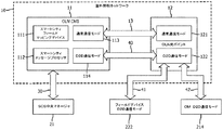
図1に示されるように、様々な実施形態では、OLN又は本明細書で言及される他のネットワーク通信プロトコルに関する専用のメッシュタイプネットワーク内にそれぞれが統合されている、複数のフィールドデバイス/光ポイント12を詳細に示す、OLN10が提供される。このOLN通信ネットワークは、有線又は無線とすることができ、光ポイント12と、一次制御システムであるOLN中央管理システム11(OLN central management system;OLN CMS)との間の通信を可能にすることができる。OLN CMSは、数ある要素の中でもとりわけ、関連プロセッサ818、記憶サブシステム824、ファイル記憶826、及びメモリサブシステム825を備える、サーバ60又は他のコンピュータであってもよく、その一実施例は、図13Aの要素を含んでもよい。OLN CMS11は、接続されている屋外照明システムを制御、監視、及び管理し、光ポイント/フィールドデバイス12のそれぞれは、標準ネットワーク通信モード経路13を介して、OLN CMS11と通信している。多くの他の実装形態及びトポロジが利用されてもよいため、様々な図に示される経路13は、例示的なものに過ぎないばかりではなく、メッシュネットワークの暗示的なトポロジである。通常動作下では、CMSは、OLN通信リンク13に固有の物理ネットワーク及び通信プロトコルを使用して、OLNフィールドデバイス/光ポイント12とデータを交換する。
As shown in FIG. 1, in various embodiments, multiple field devices / optical points, each integrated within a dedicated mesh type network for OLN or other network communication protocols referred to herein. OLN10 is provided, showing 12 in detail. This OLN communication network can be wired or wireless and can enable communication between the
一部の変形態様では、CMS11は、ピアツーピアネットワーク接続30の上で、専用のアプリケーションレベルのセンタ間(center-to-center)C2C通信プロトコルを使用して、スマートシティシステム20とのデータ交換を確立してもよい。
In some variants, the
そのような専用通信チャネルは、ネットワークインタフェース816又は他の同様のアーキテクチャを介して、CMS11と直接統合されてもよい。C2Cリンク30及び通信経路は、スマートシティシステムCM21とOLN CMS11との間の相互接続及びデータ転送のために、特に、マッピング、デバイス位置特定、及びサービスネットワークマップに関する更新のために、様々な実装形態で利用されてもよい。そのようなC2C通信接続30はまた、諸態様では、本明細書で論じられるように、D2D動作モードにある場合の、フィールドデバイス間の通信用の伝送経路とすることもできる。
Such dedicated communication channels may be integrated directly with
同様に、図1では、実施形態では中央マネージャ21、アクセスポイント、及び複数のユーザ機器(UE)22を含んでもよい、スマートシティシステム20が示されている。スマートシティシステム20は更に、様々な実装形態では、中央マネージャ21、及び上述のように、UE/フィールドデバイス22をオプションとして含んでもよい。一実施形態では、スマートシティシステムは高度道路交通システム(ITS)であってもよく、これにおいて、中央マネージャ21は、交通管理センタ、事故管理センタ、運行管理センタ、旅行者情報センタなどのITSセンタであり、フィールドデバイス22は、交通制御デバイス、動的メッセージ標識、交通カメラなどであってもよい。C2C通信30は、明確に定義された情報レベルの辞書(例えば、TMDD)を含んでもよく、データは、ウェブサービスを使用して、アプリケーションレベルで、eXtensible Markup Language(XML)又はDATEX IIを介して交換されてもよい。別の実施形態では、スマートシティシステム20は、中央マネージャがコミュニティ緊急管理センタ21である、都市緊急警報システムを含んでもよく、フィールドデバイス22は、緊急対応車両、このシステムに加入しているスマートフォンなどであってもよい。中央マネージャ21は、実施形態では、スマートシティシステムの監視、制御、及び管理を担当するコンピュータシステムから成り、OLN CMSと共に使用される、上述のような対応するアーキテクチャ上の特徴を有してもよい。標準の動作下では、中央マネージャは、スマートシティシステムに固有のネットワークプロトコル及び媒体を使用して、フィールドデバイスUE22との通信及び接続性23を確立してもよく、一部の実装形態では、WAN又は図示のようなアクセスポイントを経由してもよい。
Similarly, FIG. 1 shows a
様々な実装形態では、標準の通信下では、OLN CMS11は、無線及び/又は有線、若しくはそれらの組み合わせであってもよい通信チャネル13を介して、様々な光ポイント及び/又はセンサ12を制御することになる。屋外照明管理において既知であるような、様々な特徴が実装されてもよい。しかしながら、予想され得るように、様々な光ポイント12は、都市全域にわたって均等に地理的分布されてもよく、OLN CMS11又は代替OLNシステムの制御下の、全て又は一部のサブセットが、図示のようにOLN10と統合されてもよい。そのような光ポイント12は、それらの均等な地理的分布により、一部の実装形態では、通信ネットワークチャネル23などの一次通信チャネルが障害を起こした場合のアドホックD2Dネットワークに関する、D2D通信エントリポイントとして利用されてもよい。非常時インフラストラクチャのアドホックな性質の結果として、OLN CMSは、図5に示されるように、SCSデバイスサービスマップ250bと共に、OLNデバイスサービスマップ150bを維持してもよい。同様のサービスマッピングが、SCS CM及び関連のネットワーク管理システムによって維持されてもよい。
In various implementations, under standard communication, the
図4に示されるように、屋外照明ネットワーク10は、OLN CMS11及び複数のOLNデバイス/光ポイント12の双方を含むか、又は組み込んでもよい。OLN CMS11は、一部の実施形態では、スマートシティシステムデバイスマッピングメカニズム111、スマートシティメッセージプロセッサ112、通常通信モード113、及びD2D通信モード114から成るものであってもよい。OLN CMS11は、数例を挙げると、マッピングの転送、デバイス及び他の制御データ及び報告データの交換のために、C2Cリンク30を介してSCS中央マネージャ21と通信してもよい。サーバ/管理システム間での、及びスマートシティシステム内でのそのような通信交換は、著しい数の動作パラメータを含んでもよく、そのような説明は、本明細書で説明される実施形態又はアーキテクチャに限定されるものではない。
As shown in FIG. 4, the
OLN10内の光ポイント12のそれぞれは、LED又は他の光発生構造体などの照明源を含んでもよく、また、照明及び通信を適切に制御するための、プロセッサ及び関連メモリを含んでもよい。それゆえ、通信ポート/経路が、光ポイント内に組み込まれてもよく、それらは、複数の通信モードをサポートするための、有線通信又は無線通信のいずれかを含んでもよい。また、光ポイントのそれぞれは、様々な実装形態では、メモリ上に記憶され、プロセッサによって実行可能な命令を含んでもよく、それらの命令は、照明源の照明を制御すると共に、他の光ポイント、中央管理サーバ、並びに他のデバイスに対する、その光ポイントによるメッセージ及び通信処理を制御する。そのようなオンボードのエレクトロニクス及び命令は、本明細書で論じられるように、複数の通信モード及び非OLNデバイスにわたる、メッセージの処理及び転送をサポートする。
Each of the light points 12 in the
OLN CMS11のスマートシティシステムデバイスマッピングメカニズム111は、様々な実装形態では、照明ネットワークサービスマップに、スマートシティフィールドデバイス22を地理的に相関させてもよい。別個のOLNデータベースマップ150b及びSCSデバイスマップ250bが、OLN CMS11によるアクセスのために維持されてもよく、又は統合されてもよい。デバイス及びデータベースマップ150b及び250bは、別個に維持されてもよく、一体に統合されてもよく、又は定期的に相関されてもよい。同様に、実装アーキテクチャに応じて、それらデータベース及び/又はマップのローカルコピー又はマスタコピーが、サブネットワークのそれぞれにアクセス可能なオフサイトの場所に維持されてもよい。デバイス識別子、座標、機能セットなどを含めた、スマートシティフィールドデバイスに関する情報が、C2C通信30を通じて、スマートシティシステム中央マネージャ21から取得され、照明ネットワークサービスマップ内に組み込まれるか、又は照明ネットワークサービスマップと統合されてもよい。このマッピングにより、OLN CMSは、特定のスマートシティデバイスの正確な位置を決定して、近傍の光ポイント又は他のOLNフィールドデバイスを識別することが可能となる。
The smart city system
実装形態では、図4に示されるように、OLN CMS11は、複数のOLN光ポイント12への通常通信経路13を含んでもよく、また、デバイス12への代替通信経路のための、切り替え可能なD2D通信モード114を含んでもよい。D2Dモードにある場合、OLN CMS11は、D2D通信経路40を介して、OLN光ポイントに通信してもよい。
In an implementation, as shown in FIG. 4, the
OLN光ポイント/デバイス12は、通常通信モード121並びにD2D通信モード122の双方を含んでもよい。D2D通信モードにある場合、光ポイント12は、通信リンク41を介して、SCSフィールドデバイス22と通信してもよい。本明細書で論じられるような他の実装形態では、光ポイント12は、更に、通信障害状態下の場合に必要とされ得るように、D2Dリンク42を介して、D2D通信モード214のSCS CMと直接通信してもよい。
The OLN optical point /
同様に、図5に示されるように、OLN CMSは、複数のデバイス121〜12Nにリンクされてもよい。CMSは、更に、様々な他の実施形態では、OLNデバイス発見プロセス132、通信回線検出プロセス131、OLN及びSCSデバイスマッピングメカニズム111、並びに、OLN及びSCSシステム20の双方からのデバイスをOLNサービスマップ内で相関させるための、OLNマップ相関器132を有してもよい。
Similarly, as shown in FIG. 5, OLN CMS may be linked to
OLN121〜12Nの様々な複数の光ポイント又はフィールドデバイスは、それぞれ、以下で言及されるように、光ポイントのそれぞれが、D2Dモードにある場合に、通信中継のために近傍のD2Dデバイスを発見及び検出することを可能にする、関連デバイス発見プロセスを有してもよい。そのようなデバイス検出プロセスは、OLNフィールドデバイス12が、近傍のD2D対応デバイスの位置を特定して、そのデバイスから関連の他の近傍デバイスへの、データ中継器として機能することを可能にする。更には、OLNのフィールドデバイス12は、通信リンク13のタイムアウト条件によって、又は他の手段を通じて、システム全体の通信障害を自律的に検出及び決定してもよく、一次的な第1の通信プロトコルから二次的なD2Dプロトコルに自動的に切り替わってもよい。
OLN12 1 ~12 N different plurality of light points or field devices, respectively, as mentioned below, each light point, when in D2D mode, the D2D device in the vicinity for communication relay It may have a related device discovery process that allows it to be discovered and detected. Such a device detection process allows the
同様に、スマートシティシステム20及びSCS CM21の一実施例である、図3及び図6に示されるように、SCS20は、OLNフィールドデバイスマッピングメカニズム211、OLNメッセージプロセッサ212、通常通信モード213、及びD2D通信モード214を有する、中央マネージャ21を含む。通常通信モードプロセスは、中央マネージャ21とSCSフィールドデバイス22との間の、通常通信モードプロセス221を通じた通信を可能にする。同様に、D2D通信プロセッサ214は、SCS CM21とOLN光ポイント/デバイス12の通信モードプロセッサ122との間の、通信チャネル42を介した直接D2D通信を可能にする。そのような直接接続は、本明細書で説明されるように、一次通信経路の通信システム障害の後であっても、OLN照明ネットワーク10の様々な構成要素を介した、SCSフィールドデバイス22とSCS CM21との間のホップバイホップ通信中継を可能にする。SCSフィールドデバイス22は、OLN10を介したホップバイホップ中継を開始するための、OLN光ポイント12のD2D通信モードプロセッサ122との通信を可能にする、D2D通信モードプロセス222を更に有する。これらのSCSのフィールドデバイス22は、同様に、それらの一次通信ネットワークからD2Dネットワークに自律的に切り替わることができ、OLNフィールドデバイス12で同様に言及されたような、デバイス発見手段を含み得る。
Similarly, as shown in FIGS. 3 and 6, which are examples of the
図6の実施例では、SCS CM21は、そのCM21に接続されている、複数のフィールドデバイス221〜22Nを含んでもよい。中央マネージャ21はまた、OLNメッセージプロセッサ212、フィールドデバイス発見プロセッサ232、OLN及びSCフィールドデバイスマッピングメカニズム211、並びにSCS & OLNマップ相関器232を含んでもよく、これらのいずれかは、OLNマップ150a及びSCSデバイスマップ250aと通信してもよい。SCS CM21は、直接又はリモートのいずれかで、一次チャネル通信回線障害を検出することが可能な、通信検出プロセッサ231と共に、D2D通信モードプロセッサ214及び通常通信モードプロセッサ213を更に含むことにより、D2D通信モードを開始させてもよい。OLNメッセージプロセッサ212はまた、いずれの通信モードが使用されているかに基づいて、各OLNメッセージにメッセージ優先度も割り当てる。各通信モードメッセージ優先度は、1つ以上の動作モード基準、例えば、(第1の)通常動作モードの基準セット、又は(第2の)緊急モードの基準セットに基づく。各通信モードに関するメッセージ優先順位付けはまた、例えば、動作中のOLN光ポイント12又はスマートシティフィールドデバイス22の数、緊急事態の性質などに基づいて、動的に行われることもできる。
In the embodiment of FIG. 6, the
一般に、及び一部の実施形態では、本明細書に記載される特徴は、OLN CMS11とスマートシティシステム中央マネージャ21との間の、センタ間(C2C)データ交換スキームを含んでもよい。SCS CM及びOLN CMSの双方のシステムは、デバイス位置及びサービスマップの情報が最新状態に保たれ、相関されることができるように、OLN CMSと他のスマートシティ中央マネージャとの間での、デバイス情報及びサービスネットワークマップのデータ交換を提供する。一部の例では、単一のOLNデバイスサービスマップ150aデータベース及びSCSデバイスサービスマップ250aデータベースが維持され、更に統合されてもよい。他の代替案では、各中央管理システムは、それら自体の、関連データベース/マップのコピーを有してもよい。
In general, and in some embodiments, the features described herein may include a center-to-center (C2C) data exchange scheme between the
OLN CMS11は、更に、D2D通信能力が装備されてもよく、専用のOLN通信プロトコルと、通常通信が障害を起こした場合のD2Dモードとの間で、動作可能に切り替わることができる。スマートシティシステム20内での一次通信経路障害の通知は、通信リンク30を介して、SCS CM21から直接届いてもよく、その通知は、次いで、通信回線13を介して、又はD2D通信経路42を介して、OLNシステム全体にわたって伝搬されてもよい。同様に、様々な実施例では、ブロードキャスト状態メッセージが、通信回線状態情報と共に、ネットワークを通じて伝搬してもよい。同様に、一部の実施形態では、OLN CMS11とSCS CM21との間のメッセージ応答時間遅延、EUフィールドデバイス、光ポイント、及び/又は、D2Dモードでのブロードキャストデバイス発見通知が、通信状態トリガイベントとして利用されることができる。
The
様々な態様では、OLN光ポイント12は、D2D通信プロセス及び/又はプロセッサが装備されてもよく、通常通信が障害を起こした場合、及び/又は通信リンク障害のメッセージが受信された場合に、D2D通信モードに切り替わることができる。同様に、スマートシティシステム中央マネージャ21は、D2D通信能力が装備されてもよく、通常通信が障害を起こした場合に、D2Dモードに切り替わることができる。更には、一部の実施形態では、スマートシティフィールドデバイス22は、D2D通信能力が装備されてもよく、通常通信が障害を起こした場合に、D2Dモードに切り替わることができる。それゆえ、本明細書で説明される、屋外照明ネットワーク要素とスマートシティシステム要素との組み合わせは、一次通信経路障害の後であっても、SCSフィールドデバイスの継続的通信を可能にするための、OLN光ポイント12とスマートシティシステムフィールドデバイス22との間の共通のアプリケーション層プロトコルを含む、D2D通信スキームを含んでもよい。そのような機能性は、例えば、フィールドデバイスからの任意の通信及び/又はデータの、OLN光ポイント12を介したホップバイホップ中継によってサポートされ、継続的かつロバストな通信を維持することができる。
In various embodiments, the OLN
図1に示されるような、OLNを非常時接続性インフラストラクチャとして使用する一部の実装形態では、光ポイントが、D2D通信モードへと切り替えられる。図2(a)に示されるシナリオでは、C2C通信リンク30は、他の全ての通常通信ネットワークが途絶されている間も、影響を受けていない。スマートシティシステム中央マネージャは、C2C通信リンクを使用して、OLN CMSにメッセージを送信してもよい。OLN CMSは、D2D通信モードに切り替わり、最も近い光ポイントに、D2D通信を使用してメッセージを送信する。メッセージは、その後続けて、ターゲットのD2D対応スマートシティフィールドデバイス22に到達するまで、中間光ポイントのペア間のD2D通信を使用して中継される。同様に、戻りの通信は、屋外照明ネットワーク内のD2D対応光ポイント12への、フィールドデバイス22による送信を介して実施されてもよい。関連の宛先及び/又はアドレス情報が、後続のD2D対応デバイスによる処理のために、メッセージヘッダ内に含まれてもよく、それにより、複数及び現在のOLNの非常時接続性インフラストラクチャを介した、フィールドデバイス22からSCS CM21へのデータの転送を可能にする。
In some implementations that use OLN as an emergency connectivity infrastructure, as shown in FIG. 1, the optical point is switched to D2D communication mode. In the scenario shown in FIG. 2 (a), the
図2(b)の例では、C2C通信30もまた途絶されているが、スマートシティシステム中央マネージャは、D2D通信モードに切り替わることが可能である。この場合には、意図されているメッセージは、D2D通信を使用して、スマートシティ中央マネージャから、最も近い光ポイント及び/又はOLN CMSに送信されてもよく、次いで、そのメッセージは、ターゲットの宛先スマートシティフィールドデバイスに到着するまで、D2D通信を使用する中間光ポイントのペアを介してルーティングされる。
In the example of FIG. 2B, the
いずれかの通信回線の途絶の前に、SCS CMは、フィールドデバイス発見プロセス232を介して、全てのフィールドデバイスを検出していてもよく、フィールドデバイスは、SCSデバイスマップ250a内にカタログ化されて記憶されており、SCS通信ネットワークと、かつまた、一部の変形態様では、隣接するOLNネットワークとも相関されている。同様のプロセスが、プロセス132を使用して、OLN CMにおいて実施されてもよい。そのようなデバイス識別、マッピング、地理的配置は、SCSデバイスマップ内に記憶されてもよく、隣接するOLNのデータ交換から受信された追加情報に基づいて、相関されたマッピング情報がカタログ化されることができる。OLN及びSCSデバイスマッピングメカニズムと共にSCS及びOLNマップ相関器232によって作成された、この相関データは、デバイスを有効に地理的に位置特定して、それらのデバイスの、互いに対する、それらのネットワークに対する、及び隣接するD2D可能ネットワークに対する相対位置を決定し、適切なデータ経路を決定することができる。更には、相関器によって作成された情報は、それぞれのデータベース150a及び250a内に記憶されてもよく、それらのデータベースは、様々な他の実施形態では、組み合わされてもよい。データベース内に表されている、これらのマッピングされたフィールドデバイス及びネットワークは、次いで、通常通信モードが障害を起こした場合のメッセージルーティングのために、SCS CM21に利用可能となる。
Prior to any communication line interruption, the SCS CM may have detected all field devices via the field
それゆえ、様々な実装形態では、OLNフィールドデバイスマッピングメカニズム211は、OLNフィールドデバイス12をスマートシティサービスマップに地理的に相関させており、そのような情報を、関連のデータベース内に記憶させてもよい。OLNデバイスのアイデンティティ及び位置などの情報は、C2C通信30を通じてOLN CMS11から取得され、スマートシティシステムサービスマップ内に組み込まれてもよい。SCSのフィールドデバイス及びネットワークのシステムマップばかりではなく、関連OLNのシステム情報、デバイス、及び位置もまた最新状態に維持することによって、中央マネージャは、そのフィールドデバイス22を、OLNシステム10内の屋外照明ネットワーク光ポイント12と地理的に関連付けてもよい。
Therefore, in various implementations, the OLN field
代替的実装形態では、OLN CMS11もまた同時に、データ共有モードに関連して、又はデータ共有モードにおいて、SCS及びOLNの双方からのフィールドデバイスの位置認識を同様に維持するために、OLN及びSCSデバイスマッピングメカニズム111をOLNマップ相関器132と共に利用してもよい。様々な実装形態では、OLNに関するデバイスマップ150b/250bは、共有マッピングデータベースであってもよく、シャドウマッピングデータベースであってもよく、又は、様々な同様のシステムマッピング間の可変周波数データ相関を使用して、OLN CMS内で独立して維持されてもよい。
In an alternative implementation, the
一実施例では、図1と組み合わせて、図2Aの実施形態で示されるように、OLN10は、光ポイント12がD2D通信モードへと切り替えられる、非常時接続性インフラストラクチャとして設けられている。図示の実施例では、C2C通信回線30は、SCS CM21とSCSフィールドデバイス22との間の通常通信ネットワーク23が途絶されている間も、影響を受けていない。SCS CMは、通信検出プロセス231を介して、そのような通信途絶を検出してもよく、次いで、そのネットワークを通じて、又は、このシステムの隣接ネットワークを通じて、そのような情報を中継してもよい。あるいは、システム内のいずれかのネットワークの個々のデバイスが、そのようなネットワーク障害を自律的に決定して、D2D通信モードに切り替わってもよく、同様に、通常の通信経路を使用するシステムリンク有効状態を認識した後に、切り替わって戻ってもよい。
In one embodiment, in combination with FIG. 1, as shown in the embodiment of FIG. 2A, the
上記の実施例で述べられたように、センタ間一次通信経路30は、図示のように利用可能であってもよく、SCS CM21からフィールドデバイスへのメッセージは、変換されたOLN10を介してルーティングされてもよい。そのような実施形態では、SCSフィールドデバイス22は、通常通信リンク23の障害により、SCS CM21との通信から事実上解除される。そのような実施形態では、スマートシティシステム中央マネージャ21は、OLNシステムマップ情報及び光ポイント12を通信経路として統合することによって、フィールドデバイスにメッセージを送信するための適切なルートを決定してもよい。SCS CMは、次いで、C2C通信チャネル30を使用するOLN CMSを介して、屋外照明ネットワークを通じてフィールドデバイスにメッセージを送信してもよい。SCS CMからメッセージを受信すると、スマートシティメッセージプロセッサ112は、C2C通信30を通じてスマートシティシステム中央マネージャから受信されたデータを復号してもよく、D2Dモード114で分散型デバイス12に通信される際に、それらOLNデバイスによって認識されることが可能なメッセージを符号化してもよい。異なるネットワーク間でメッセージを送信する際、そのメッセージは、D2Dモードで通信している場合のOLNフィールドデバイス及びSCSフィールドデバイスの双方によって認識されることが必要となる。それゆえ、本システムは、実装形態では、分散型デバイス12を介したD2Dモードメッセージ処理を可能にするように、スマートシティメッセージプロセッサ112によってメッセージを符号化することにより、その混在システムメッセージは、OLNフィールドデバイス12及びSCSフィールドデバイスの双方によって認識される。メッセージの符号化は、実装形態では、メッセージの最終ホップが、OLNフィールドデバイスからSCSフィールドデバイスへのものとなるため、必要とされてもよい。あるいは、OLN CMS11とデバイス12との間の通信経路13が利用可能である場合には、メッセージは、屋外照明ネットワーク10を通じて個々のSCSフィールドデバイス22に中継するために、通常通信モード113を介して中継されてもよい。そのような実施形態では、通常のOLN通信ネットワークリンク13を使用する場合であっても、OLNフィールドデバイスは、図2Aに通信リンク41として示されるように、SCSフィールドデバイスにメッセージを受け渡す際にD2Dモードに切り替わることが依然として必要となる。
As described in the above embodiment, the center-to-center
それゆえ、実装形態では、OLNデバイス/光ポイント12は、2つの通信モードである、通常通信モード121及びD2D通信モード122を有してもよい。通常通信モード121では、そのデバイス及びネットワークは、OLN CMS11とのデータ交換のために、そのOLN固有のネットワークプロトコルを利用してもよい。あるいは、OLN光ポイント12は、通常通信チャネル13が利用不可能な場合に、あるいは、OLN CMS及び/又はSCS CMからのブロードキャストメッセージ若しくは命令などの代替手段、又は他の手段によってアクティブ化されることが可能な、D2D通信モード122に切り替わってもよい。更には、OLN光ポイント12は、通常通信モードでの、他のOLN光ポイント12又はOLN CMS11との通常の接続性の確立に失敗した後に、自律的にD2D通信モードに切り替わってもよい。
Therefore, in an implementation, the OLN device /
あるいは、屋外照明ネットワーク10のフィールドデバイス/光ポイント12が、D2D通信モード122にある場合、それらOLN光ポイント12は、共通のアプリケーション層プロトコルを使用して、そのセルラ信号受信範囲内の任意の他のデバイスとデータを交換することができる。一実施形態では、OLNデバイス12は、D2D通信を使用して、近傍のピアOLNデバイスとデータを交換する。別の実施形態では、OLNデバイスは、CMSが所定の通信範囲内にある場合、D2D通信リンク40を使用して、そのOLN CMS11と直接データを交換することができる。他の態様では、OLNデバイス12は、同じくD2D通信モードで動作する近傍のスマートシティシステムフィールドデバイス22と、通信チャネル41を介してデータを交換するように動作可能である。
Alternatively, if the field device /
OLN CMSは、ブロードキャストメッセージング、又は、SCS CM若しくは他のデバイスからOLN CMSへの他のデータ転送を介して、又は自律的な決定の際に、SCSに関する一次通信ネットワークが障害を起こしていることを決定してもよい。CMSからフィールドデバイスに転送されることになるメッセージを受信すると、OLN CMSは、D2D通信モード114に切り替わり、D2D通信モードチャネル40を使用して、そのメッセージを最も近い光ポイントに送信してもよい。このメッセージは、次いで、D2D通信モード222で動作しているターゲットのD2D対応スマートシティフィールドデバイスに到達するまで、中間光ポイントのペア間のD2D通信を使用して中継されてもよい。
The OLN CMS indicates that the primary communication network for the SCS is failing through broadcast messaging or other data transfer from the SCS CM or other device to the OLN CMS, or during autonomous decisions. You may decide. Upon receiving the message that will be transferred from the CMS to the field device, the OLN CMS may switch to
メッセージが宛先アドレスに到着するまで、D2Dモードの各ノード/OLNデバイスによって、ホップバイホップ方式でメッセージを処理する際に、標準プロトコルが使用されてもよい。メッセージコンテンツ又は他のデータのそのようなアドホックな中継は、屋外照明ネットワークから形成されている、新たに形成されたD2Dネットワーク内で実施されてもよく、受取先/宛先によって受信されるまで、そのネットワークを介してメッセージが中継されるように、データコンテンツの受取先/宛先のタグ付けを利用して実施されてもよい。 Standard protocols may be used in processing messages in a hop-by-hop manner by each node / OLN device in D2D mode until the message arrives at the destination address. Such ad hoc relay of message content or other data may be performed within a newly formed D2D network formed from an outdoor lighting network, which may be carried out until received by the recipient / destination. It may be implemented by utilizing the tagging of the recipient / destination of the data content so that the message is relayed over the network.
一部の実装形態では、OLN CMS11は、スマートシティシステムの通信障害の通知の後に、その屋外照明ネットワークの動作、及び個々の光ポイント若しくはデバイス12の動作を修正してもよい。そのような通知は、ブロードキャスト、ユニキャスト、又は他の方法によって受信されることができ、あるいは、SCS CMとOLN CMSとの間のデータ交換内に埋め込まれることもできる。D2D通信モードに切り替えることを要求する、光ポイント又はOLNフィールドデバイス12への後続の通知は、本明細書で言及されるように、OLN CMSによって、又はSCS CM若しくは他の手段によって開始されてもよい。同様に、一次通信チャネルが動作可能状態に戻されると、一次通信プロトコルに戻るために、ブロードキャスト又は他のメッセージがネットワークを介して中継されてもよい。
In some implementations, the
代替的実装形態では、C2C通信リンク30は、図2Bに示されるように影響を受ける場合がある。この実施例では、C2C通信が途絶されているが、スマートシティシステム中央マネージャは、D2D通信モードに切り替わるように動作可能である。そのような実装形態では、いずれの転送されるメッセージも、D2D通信を使用して、スマートシティ中央マネージャから、最も近いOLN光ポイント12に送信されてもよく、次いで、そのメッセージは、ターゲットのスマートシティフィールドデバイスに到着するまで、D2D通信を使用する中間光ポイント12のペアを介してルーティングされる。
In an alternative implementation, the
様々な実装形態では、OLNデバイス12は、OLN CMS11を完全に迂回して、近傍のスマートシティシステム中央マネージャ21とデータを交換するために、D2D通信モード122を実施して、D2D通信チャネル42に沿ってデータを交換することができ、この近傍のスマートシティシステム中央マネージャ21は、同じアプリケーション層プロトコルを使用して、D2D通信モード214で動作することができる。
In various implementations, the
屋外照明ネットワークに関連して、様々な実装形態では、スマートシティシステム中央マネージャ21は、OLNフィールドデバイスマッピングメカニズム211、OLNメッセージプロセッサ212、通常通信モード213、及びオプションのD2D通信モード214を含んでもよい。
In relation to the outdoor lighting network, in various implementations, the smart city system
図3に示されるOLNフィールドデバイスマッピングメカニズム211は、様々な実装形態では、様々な複数のOLN光ポイント/フィールドデバイス12を、スマートシティサービスマップに地理的に相関させるように動作可能である。複数のデバイスに関する、OLNデバイスアイデンティティなどの情報は、C2C通信30を通じてOLN CMS11から取得され、スマートシティシステムサービスマップ内に組み込まれてもよい。SCS中央マネージャは、それゆえ、そのフィールドデバイス22を、OLNシステム10内の光ポイント12と地理的に関連付けて、そのSCSフィールドデバイス22に隣接する様々なネットワークの範囲を認識するように動作可能である。
The OLN field
更には、また加えて、スマートシティシステムCM21、OLNメッセージプロセッサ212に関する実装形態は、メッセージのルーティングに応じた、2つの能力を組み込んでもよい。第1の態様では、OLNメッセージプロセッサ212は、OLNフィールドデバイスマッピングメカニズム211で使用するために、通常動作時にC2C通信プロトコル30を通じてOLN CMS11から受信されたデータを復号してもよい。OLNのデバイス12に関する、OLN CMS11から受信された情報及び他の関連データは、SCSのネットワーク及びデバイスに関連して地理的に相関及びマッピングされ、迅速な参照のために維持されることができる。また、メッセージプロセッサ212は、屋外照明ネットワークを介してスマートシティフィールドデバイス22に転送されることになる、D2D通信経路42を介したメッセージを、D2Dモード214でOLNデバイス12に直接通信される際に、そのOLNデバイス12によって認識されることが可能なフォーマットで、符号化するように動作可能であってもよい。それゆえ、そのような動作可能性の結果として、D2D通信モード214は、SCS CM21が、通常通信モード213を使用して接続性障害を経験している場合にアクティブ化されてもよく、光ポイントのOLNネットワークは、切り替え可能なD2D通信能力を使用して、非常時接続性インフラストラクチャを提供する。
Furthermore, in addition, the implementation of the smart city system CM21 and the
SCS CM21の別の態様では、通常通信チャネル23が途絶されているが、C2C通信チャネル30が損なわれていない場合、中央マネージャは、そのC2C通信リンク30を介して、意図されているSCSターゲットフィールドデバイスにOLN CMS11を通じてメッセージを転送するように動作可能であってもよい。メッセージは、次いで、OLNデバイス/光ポイント12のペア間のD2D通信40、41を使用して、OLN CMS11から、中間OLNデバイス12を介して、ターゲットのスマートシティフィールドデバイスへと、ホップバイホップでルーティングされてもよい。
In another aspect of the SCS CM21, if the
別の実装形態では、通常通信モードチャネル23及びC2C通信チャネル30が双方とも途絶されており、中央マネージャ21がD2D通信が可能である場合、その中央マネージャ自体が、リコンフィギュレーションされたOLNフィールドデバイス12との直接通信のために、D2D通信モード214に切り替わってもよい。OLNメッセージプロセッサ212は、次いで、意図されているフィールドデバイスに対するメッセージを、D2D通信アプリケーション層においてOLNデバイスによって認識可能な通信フォーマットで符号化してもよく、そのメッセージを、D2D通信チャネル42を使用して近傍のOLNデバイス12に送信する。このメッセージは、次いで、D2D通信42、41を使用して、意図されているSCSターゲットフィールドデバイス22に到達するまで、一連の中間OLNデバイス12を介してルーティングされてもよい。そのような実装形態では、スマートシティフィールドデバイス22は、2つの通信モードである、通常通信モード221及びD2D通信モード222を有してもよい。通常通信モード221は、一部の実装形態では、中央マネージャ21とのデータ交換のために、そのスマートシティシステムに固有のネットワークプロトコルを使用してもよい。更には、SCSフィールドデバイス22のD2D通信モード222は、通常通信チャネル23における途絶を検出する場合に、フィールドデバイス22自体によって自律的にアクティブ化されることができる。D2D通信モード222は、それゆえ、フィールドデバイスが、そのセルラ信号範囲内の他のエンティティと、共通のアプリケーション層プロトコルを使用してデータを交換することを可能にするように動作可能である。そのような他のデバイスは、言及されるように、チャネル13を介して標準通信モード121で通信してもよく、なおかつ、宛先に応じてチャネル40/41/42を使用するD2D通信モード122に切り替わるようにも機能する、切り替え可能な屋外照明ネットワークフィールドデバイスを含む。当然ながら、これらの様々なチャネルは、単一のチャネルとすることができ、単一のアプリケーション層を使用することもできるが、様々な実施形態の別個の通信経路を示すために、別個に示されている。同様に、様々な他の通信チャネルが、図中では別個に示される場合もあるが、実際には、OLNフィールドデバイス及びOLN CMSの使用及び動作において、同じ又は異なる通信コンフィギュレーション、プロトコル、若しくはアプリケーション層を含んでもよい。アプリケーション層とは、通信ネットワーク内のホスト及び他のデバイスによって使用される、共有のプロトコル及びインタフェース方法を指定する、抽象化層を含むことを意味する。
In another implementation, if both the normal
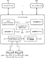
一部の実装態様では、図7で詳述されるように、SCS CMは、説明された様々な方法及び特徴を実施するために記憶されている命令を有する、メモリを有してもよく、それらの命令は、プロセッサ上での実行を通じて実施される。図示の実施例で詳述されるように、SCS CM21は、ステップ550で、そのネットワーク検出可能区域内の、フィールドデバイス22を識別してもよい。ステップ552で、SCS CMは、更に、SCSフィールドデバイス22を地理的に位置特定してもよく、次いで、ステップ554で、SCSデバイスマップデータベース250a内に位置付けられている、SCSデバイスマップ及びサービスネットワークマップを更新してもよい。同様のデータベースが、屋外照明ネットワーク10のデータベース250bなどの、周辺ネットワークで保持されてもよく、そのようなデータベースは、データ交換を介してルーチン的に相関されてもよい。分散型のデータセットを利用することは、各管理システムが自律的に、対応するマップを検出及び更新して、そのサービス区域内のフィールドデバイスの集団を地理的に位置特定することを可能にし得る。
In some implementations, as detailed in FIG. 7, the SCS CM may have a memory with instructions stored to implement the various methods and features described. These instructions are executed through execution on the processor. As detailed in the illustrated embodiment, the
ステップ558で、屋外照明ネットワーク10などの、様々な周辺ネットワークが識別されてもよく、C2C通信30を介した相関通信が、それら様々なネットワークの管理機能を処理する2つのサーバ間で行われてもよい。識別されたあらゆる屋外照明ネットワークは、ステップ562で、相関されてカタログ化されてもよく、一部の実施例では、SCSネットワークに対して位置付けられてもよい。最終的に、SCS CMによって取得されたデータは、ステップ564で、OLN CMSと交換されてもよく、それにより、双方のマップが相関され、更新され、維持されてもよい。
In
図8に示されるような、SCS CMと外部ネットワークとの間のデータ転送に関する実装形態で示されるように、SCS CMは、変換されたOLNシステム及びネットワークを、ネットワーク障害の間の非常時接続インフラストラクチャとして利用するように動作可能であってもよい。 As shown in the implementation for data transfer between the SCS CM and the external network, as shown in FIG. 8, the SCS CM connects the transformed OLN system and network to the emergency connection infrastructure during a network failure. It may be operable to be used as a structure.
実装形態では、ステップ572で、SCS CMは、SCSネットワーク20内で処理するためのメッセージをステップ572で受信してもよい。SCS CMは、例えばステップ574で、タイムアウト通信クロックを通じて、又は状態メッセージングを介して、フィールドデバイス22への一次通信ネットワーク23の、通信ネットワーク障害又はシステム障害を決定してもよい。中央マネージャは、ステップ578で、C2C通信回線30がアクティブであるか否かを決定してもよく、アクティブである場合には、適切なアドレス指定を使用する、OLN CMへのリンクを通じたメッセージルーティングを介して、メッセージの転送を継続してもよい。OLN10を介して再ルーティングされる、そのようなデータ及びメッセージトラフィックは、OLN CMSが、そのOLN内のD2Dトランスポート層を介して、SCSフィールドデバイスにメッセージを適切にリダイレクトすることができるように、適切なアドレス指定ヘッダ及び情報を有してもよい。
In the embodiment, in
実装形態では、図8に示されるように、このSCS CMデータ転送は、SCS CMと外部ネットワークとの間で行われてもよい。様々な実装形態では、スマートシティシステム中央マネージャ21は、図2A及び図2Bに示されるように、ネットワーク障害又は途絶により、現在SCSネットワークから接続解除されているSCSフィールドデバイス22に転送するための、データ又はメッセージを有してもよい。オプションでは、SCS CMは、ステップ572で示されるように、SCSフィールドデバイス22にメッセージが送信される必要があることを決定してもよい。スマートシティシステム中央マネージャ21が、メッセージ及び適切なフィールドデバイス識別子を決定した後、このSCS CMは、通信システムが現在障害モードにあり、通信リンク23がダウンしていることを決定してもよい。言及されたように、SCS CM21は、ステップ574で示されるように、通信障害が存在していることを決定してもよい通信検出プロセス231を有する。次に、一部のアプリケーションでは、SCS CMは、サービスマップ250A/150Aに基づいて、宛先フィールドデバイス22に直接隣接している屋外照明ネットワークの位置が、関連ターゲット及び接続性インフラストラクチャであることを決定してもよく、次いで、そのフィールドデバイス22への通信経路を決定及び算出してもよい。SCS CMは、次いで、C2C通信リンク30がアクティブであるか否かを決定してもよく、アクティブである場合には、このスマートシティシステム中央マネージャ21は、ステップ580で、屋外照明ネットワークCMS11へのC2C経路30を介して、通信障害及び通信障害状態のメッセージを転送してもよく、このメッセージは、次いで、ステップ582で示されるように、屋外照明ネットワークCMS及び様々なフィールドデバイス12を、D2D通信モードに切り替えることになり、その後、OLNメッセージ処理サービス672が開始してもよい。
In the embodiment, as shown in FIG. 8, this SCS CM data transfer may be performed between the SCS CM and the external network. In various implementations, the smart city system
あるいは、一部の実施形態では、C2C経路が非アクティブであることにより、ステップ586で、SCS CM21に、D2D通信モード214を介してOLNネットワークにデータを送信させてもよい。OLNメッセージプロセッサ212は、次いで、ステップ588で、D2Dモードを介したフィールドデバイスへの送信メッセージを符号化してもよく、SCS CMは、ステップ590で、D2Dモード及び通信リンク42を介して、OLNデバイス12に送信してもよい。
Alternatively, in some embodiments, the inactivity of the C2C path may cause the SCS CM21 to transmit data to the OLN network via the
図9で概説されるように、屋外照明ネットワークシステム及びフィールドデバイスの更新に関する、例示的フローチャートが提供される。一部の実施形態では、OLN CMSは、ステップ650で、デバイス発見プロセス132を介して、フィールドデバイス12を識別してもよい。次に、OLN CMSはまた、更に、ステップ652で、ネットワークマップ内でフィールドデバイス12を地理的に位置特定してもよく、次いで、OLN CMSは、ステップ654で、関連情報を使用して、OLN CMSデバイスマップ及びサービスネットワークマップ150B/250Bを更新してもよい。OLN CMS11は、更に、ステップ658で、C2C通信30を通じてSCS CMから受信されたSCSフィールドデバイス22を地理的に相関させ、次いで、ステップ660で、そのSCSフィールドデバイス22を、OLNネットワークマップ内に組み込んでもよい。最終的に、一部の実施形態では、ステップ662で、デバイス情報データ及びサービスネットワークマップ情報を含めたデータが、通信リンクC2C30を介して、SCS CMと交換されて更新されてもよい。
Illustrative flowcharts for updating outdoor lighting network systems and field devices are provided, as outlined in FIG. In some embodiments, the OLN CMS may identify the
OLN CMS11は、オプションとして、図10Aに示されるように、スマートシティシステム中央マネージャ21から受信されたメッセージに関する、メッセージ処理プロセスを有してもよい。そのようなプロセスは、一部の実装形態では、OLN CMS11が、ステップ672で、SCS CMからSCSフィールドデバイスメッセージ又はデータを受信することを含んでもよく、それに応答して、OLN CMSは、現在OLN CMSに利用可能な様々なデータベース及びマップ150B/250Bから、そのSCSフィールドデバイスの位置を決定してもよい。示されるように、これらのフィールドデバイスマップ及びOLNデバイスマップは、スマートシティシステム中央マネージャ21のデバイスマップに関連して、相関されるか、組み合わされるか、又はリモートの場所に保持されてもよい。最終的に、OLN CMS11は、図2Aに示されるように、ステップ676で、フィールドデバイスユニット12を介した、変換された屋外照明ネットワークのホップバイホップを通じて、SCSフィールドデバイス22に、D2D通信を介して送信してもよい。
The
非常時接続性インフラストラクチャとして利用される屋外照明ネットワークはまた、図10Bのフローチャートに示されるように、SCSネットワークから、特にSCS CM21又は個々のフィールドデバイス22から直接受信されたメッセージの、個々の光ポイントを通じた処理を実施してもよい。最初に、OLN光ポイント又はフィールドデバイス12は、ステップ680で、SCSフィールドデバイス22からメッセージを受信してもよい。このメッセージ又はデータは、OLN内の個々の光ポイントによって処理するための、添付された宛先又は他のルーティング情報を含んでもよい。
The outdoor lighting network used as an emergency connectivity infrastructure is also an individual light of a message received directly from the SCS network, especially from the SCS CM21 or
OLN光ポイント又はフィールドデバイス12は、次いで、受信されたSCSフィールドデバイス22メッセージを、OLNネットワーク10を介して、隣接する光ポイント12に、デバイスツーデバイス通信リンクを通じてリダイレクトする。ステップ684で、OLN CMS11は、最終的に、SCS CMに直接ルーティングするための再ルーティングされたメッセージをステップ684で受信してもよい。
The OLN optical point or
SCSネットワークからの発信メッセージもまた同様に、最初に、複数のSCSフィールドデバイス22を通じて、それらフィールドデバイスのそれぞれがホップバイホップ又は中継通信によって近傍のフィールドデバイスを発見することにより、全てがD2D通信プロトコルを通じてルーティングされてもよい。
Outgoing messages from the SCS network are also similarly all D2D communication protocols by first discovering nearby field devices through multiple
OLN CMS11が、ルーティングするためのメッセージを受信すると、ステップ688で、C2C経路が実行可能であるか否かが決定されることになる。C2C通信リンクが利用可能である場合には、OLN CMSは、ステップ690で、C2C経路30を介して、SCS CM21にメッセージを転送することになる。あるいは、C2C経路が利用可能ではない場合には、OLN CMS11は、光ポイント又はフィールドデバイスに、D2Dプロトコルを利用して、OLNインフラストラクチャから直接SCS CM21に、D2D中継を介して直接送信するように指示してもよい。代替的実施形態では、OLN CMSは、場合により、C2C通信リンク30を迂回して、D2D通信を通じて直接送信するための、D2D通信能力を有してもよい。しかしながら、OLNフィールドユニット及び/又は光ポイントの地理的変位の幅及び範囲を考慮すると、OLN内の個々の光ポイントは、そのような場合に、SCS CMへの直接送信のために利用可能となる可能性が高く、OLN CMSは、それら個々の光ポイントに、SCS CMにルーティングされているあらゆるメッセージを、代替経路を介してリダイレクトし、OLN CMSを迂回させるように指示してもよい。
When the
図12に示されるように、OLN光ポイントは、通信システム障害を検出して、一次プロトコルから二次D2Dプロトコルに自律的に切り替わるように動作可能であってもよい。ステップ852で、OLN光ポイント12は、そのような通信障害を検出して、D2D通信モードに切り替わってもよい。ステップ854で、OLN光ポイントは、その屋外照明ネットワーク外の隣接フィールドデバイス22から、SCSフィールドデバイスメッセージを受信してもよいが、このネットワーク外のフィールドデバイスは、それ自体がD2D通信モードに切り替わっている。ステップ856で、OLNデバイス12は、同様に、そのメッセージの送信及び中継のために、隣接又は近傍のD2D可能光ポイントを発見してもよい。最終的に、ステップ858で、OLN光ポイントは、SCS CM宛先を含み得るSCSフィールドデバイスメッセージを中継してもよく、この中継は、その宛先アドレスに向けた送信のために、最も近いOLNフィールドデバイス及び/又はD2D可能デバイスに対して行われる。
As shown in FIG. 12, the OLN optical point may be capable of detecting a communication system failure and operating to autonomously switch from the primary protocol to the secondary D2D protocol. In
あるいは、図11に示されるように、同様のデバイス検出及び通信プロトコルの切り替えが、フィールドデバイス22に関して示されている。ステップ752で、SCSフィールドデバイス22は、自律的に、又はブロードキャスト通信若しくは他の手段を通じて、通常通信の途絶を検出してもよい。ステップ754で、フィールドデバイス22は、D2Dモードに切り替わってもよく、ステップ756で、このデバイスは、発見プロセスを通じて、最も近いOLN D2Dモード可能フィールドデバイス12の位置を特定してもよい。そのような隣接OLNフィールドデバイスの発見の後、SCSフィールドデバイス22は、そのネットワーク外デバイスに、中継若しくはホップバイホップ送信及びD2Dプロトコルのための、適切な宛先及びアドレス情報を有する、データ又はメッセージを送信してもよい。理解され得るように、D2D通信プロトコルを通じた中継は、適切なアドレス指定情報が提供される限り、ネットワーク内で、ネットワーク外で、又はネットワーク間にわたって行われてもよく、こうした理由により、そのような広い地理的分散を有する屋外照明ネットワークの実装が、非常時通信ネットワークとして有益である。
Alternatively, as shown in FIG. 11, similar device detection and communication protocol switching is shown for the
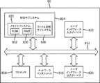
図13Aに示されるように、記憶サブシステム824と、ROM832及びRAM830を含み得る、メモリサブシステム825とを含む、OLN管理システムサーバの例示的概略図が示される。記憶サブシステム824はまた、ファイル記憶サブシステム826を含んでもよい。バス812は、記憶サブシステムを、様々なプロセッサ818、並びに、C2C通信リンク30及びOLNに関する通信プロトコルリンク13の双方のための、異なる通信プロトコル送信機を含み得る、ネットワークインタフェース816と接続してもよい。更なる実施形態では、ネットワークインタフェースはまた、サーバと光ポイントとの間、また他の通信エンドポイントとの間の、そのようなデバイスツーデバイスプロトコルでの通信に関する、図2Bに示されるようなD2Dモードでの通信を提供してもよい。同様に、ユーザインタフェース及び出力デバイス820が、包括性及びユーザインタフェースのために設けられてもよい。図13Aの概略図は、単に、屋外照明ネットワーク用の管理システムサーバに関する実装形態、又はスマートシティシステムネットワークCMサーバの実装形態の、単なる一実施例として示されているに過ぎず、それらのいずれも、図中で言及されているサブ要素のそれぞれを含むことを、必ずしも必要としない。
As shown in FIG. 13A, an exemplary schematic of an OLN management system server including a
図13Bに示されるように、記憶サブシステム924と、ROM932及びRAM930を含み得る、メモリサブシステム925とを含む、OLN光ポイント又はフィールドデバイス12の例示的概略図が示される。記憶サブシステム924はまた、ファイル記憶サブシステム926を含んでもよい。相互接続性バス912は、記憶サブシステムを、様々なプロセッサ914、並びに、第1の通信プロトコル及び第2の通信プロトコルの双方の送信機と必要な通信エレクトロニクスとを含み得る、ネットワークインタフェース916と接続してもよい。この光ポイントは、更に、様々な照明源の実装形態では、感知及び検出メカニズム、並びに様々な制御ハードウェア及びソフトウェアを含んでもよい。照明出力源940は、広域照明、街路照明、投光若しくはウォールウォッシュ照明、又は任意の他の所望の屋外照明であってもよく、必要に応じて、関連の記憶サブシステム及び/又はプロセッサと通信し得る、対応する照射若しくは照明制御922を含んでもよい。コントローラは、プロセッサ914によって実装されてもよく、又は、LEDなどの各照明源に関して、若しくは照明源のグループに関して、個別の光コントローラを有してもよい。図13Bの概略図は、単に、屋外照明ネットワークあるいはスマートシティシステムネットワークの様々な光ポイント及びフィールドデバイスに関する実装形態の、単なる一実施例として示されているに過ぎず、それらのいずれも、図中で言及されているサブ要素のそれぞれを含むことを、必ずしも必要としない。
As shown in FIG. 13B, an exemplary schematic of an OLN optical point or
図示のように、フィールドデバイスは、メモリサブシステム及びファイル記憶サブシステムの利用を組み込んでもよいが、全て又は双方を含む必要はない。同様に、ネットワークインタフェースは、基礎となる屋外照明ネットワーク又は基礎となるスマートシティシステムネットワークに関する様々な通信プロトコルに対する、メモリサブシステムからのサポートを含んでもよい。そのようなプロトコルはまた、それらのデバイスのそれぞれが全面的サポートを有して実装されるための代替的なD2Dプロトコル、及びメモリサブシステム内に記憶されている命令を含んでもよく、それらは、本明細書で説明される様々な機能性要素及び態様を実施するために、プロセッサによって実行されることができる。 As shown, field devices may incorporate the use of memory and file storage subsystems, but need not include all or both. Similarly, the network interface may include support from the memory subsystem for various communication protocols for the underlying outdoor lighting network or the underlying smart city system network. Such protocols may also include alternative D2D protocols for each of those devices to be implemented with full support, and instructions stored within the memory subsystem. It can be performed by a processor to implement the various functional elements and embodiments described herein.
いくつかの実施形態が、本明細書で説明及び図示されてきたが、当業者は、本明細書で説明される機能を実行するための、並びに/又は、その結果及び/若しくは利点のうちの1つ以上を得るための、様々な他の手段及び/又は構造体を、容易に構想することとなり、そのような変形態様及び/又は修正態様のそれぞれは、本明細書で説明される実施形態の範囲内にあるものと見なされる。より一般的には、本明細書で説明される全てのパラメータ、寸法、材料、及び構成は、例示であることが意図されており、実際のパラメータ、寸法、材料、及び/又は構成は、本技術が使用される特定の用途に応じて変化することを、当業者は容易に理解するであろう。当業者は、通常の実験のみを使用して、本明細書で説明される特定の実施形態に対する、多くの等価物を認識し、又は確認することが可能であろう。それゆえ、上述の実施形態は、例としてのみ提示されており、添付の請求項及びその等価物の範囲内で、具体的に説明及び特許請求されるもの以外の実施形態が実践されてもよい点を理解されたい。本開示の実施形態は、本明細書で説明される、それぞれの個別の特徴、システム、物品、材料、キット、及び/又は方法を対象とする。更には、2つ以上のそのような特徴、システム、物品、材料、キット、及び/又は方法の任意の組み合わせは、そのような特徴、システム、物品、材料、キット、及び/又は方法が相互に矛盾しない場合であれば、本開示の範囲内に含まれる。 Although some embodiments have been described and illustrated herein, one of ordinary skill in the art will perform the functions described herein and / or of the consequences and / or advantages thereof. Various other means and / or structures for obtaining one or more will be readily envisioned, each of such modifications and / or modifications of embodiments described herein. Is considered to be within the range of. More generally, all parameters, dimensions, materials, and configurations described herein are intended to be exemplary, and actual parameters, dimensions, materials, and / or configurations are the present. Those skilled in the art will readily appreciate that the technology will vary depending on the particular application in which it is used. One of ordinary skill in the art will be able to recognize or confirm many equivalents to the particular embodiments described herein using only routine experiments. Therefore, the above-described embodiment is presented only as an example, and embodiments other than those specifically described and patented may be practiced within the scope of the appended claims and their equivalents. Please understand the point. Embodiments of the present disclosure are directed to the respective individual features, systems, articles, materials, kits, and / or methods described herein. Furthermore, any combination of two or more such features, systems, articles, materials, kits, and / or methods may have such features, systems, articles, materials, kits, and / or methods mutually. If there is no contradiction, it is included within the scope of this disclosure.
本明細書で定義及び使用されるような、全ての定義は、辞書定義、参照により組み込まれる文書中での定義、及び/又は定義される用語の通常の意味を支配するように理解されるべきである。 All definitions, as defined and used herein, should be understood to govern the usual meanings of dictionary definitions, definitions in documents incorporated by reference, and / or defined terms. Is.
不定冠詞「a」及び「an」は、本明細書及び請求項において使用されるとき、そうではないことが明確に示されない限り、「少なくとも1つ」を意味するように理解されるべきである。 The indefinite articles "a" and "an", when used herein and in the claims, should be understood to mean "at least one" unless expressly indicated otherwise. ..
語句「及び/又は」は、本明細書及び請求項において使用されるとき、そのように結合されている要素の「いずれか又は双方」、すなわち、一部の場合には接続的に存在し、他の場合には離接的に存在する要素を意味するように理解されるべきである。「及び/又は」で列挙されている複数の要素は、同じ方式で、すなわち、そのように結合されている要素のうちの「1つ以上」として解釈されるべきである。「及び/又は」の節によって具体的に特定されている要素以外の他の要素は、具体的に特定されているそれらの要素に関連するか又は関連しないかにかかわらず、オプションとして存在してもよい。それゆえ、非限定例として、「A及び/又はB」への言及は、「含む(comprising)」などのオープンエンドの言語と共に使用される場合、一実施形態では、Aのみ(オプションとして、B以外の要素を含む)、別の実施形態では、Bのみ(オプションとして、A以外の要素を含む)、更に別の実施形態では、A及びBの双方(オプションとして、他の要素を含む)などに言及することができる。 The phrase "and / or", as used herein and in the claims, is "either or both" of the elements so combined, i.e., in some cases, connected. In other cases it should be understood to mean elements that exist distantly. Multiple elements listed in "and / or" should be construed in the same manner, i.e., as "one or more" of the elements so combined. Other elements other than those specifically specified by the "and / or" section exist as options, whether or not they are related to those specifically specified. May be good. Therefore, as a non-limiting example, the reference to "A and / or B", when used with an open-ended language such as "comprising", in one embodiment is A only (optionally B). (Including elements other than), in another embodiment only B (optionally including elements other than A), in yet another embodiment both A and B (optionally including other elements), etc. Can be mentioned.
本明細書及び請求項において使用されるとき、「又は」は、上記で定義されたような「及び/又は」と同じ意味を有するように理解されるべきである。例えば、リスト内の項目を分離する際、「又は」又は「及び/又は」は、包括的であるとして、すなわち、少なくとも1つを含むが、また、いくつかの要素又は要素のリストのうちの2つ以上、オプションとして、列挙されていない追加項目も含むとして解釈されるものとする。「〜のうちの1つのみ」若しくは「〜のうちの厳密に1つ」、又は請求項で使用される場合の「〜から成る」などの、その反対が明確に示される用語のみが、いくつかの要素又は要素のリストのうちの厳密に1つを含むことに言及する。一般に、用語「又は」は、本明細書で使用されるとき、「〜のいずれか」、「〜のうちの1つ」、「〜のうちの1つのみ」、又は「〜のうちの厳密に1つ」などの、排他性の用語に先行する場合にのみ、排他的選択肢(すなわち、「一方又は他方であるが、双方ではない」)を示すとして解釈されるものとする。「〜から本質的に成る」は、請求項で使用される場合、特許法の分野で使用される際の、その通常の意味を有するものとする。 As used herein and in the claims, "or" should be understood to have the same meaning as "and / or" as defined above. For example, when separating items in a list, "or" or "and / or" is considered to be inclusive, i.e., includes at least one, but also within some element or list of elements. Two or more, optionally, shall be construed as including additional items not listed. How many terms clearly indicate the opposite, such as "only one of" or "exactly one of", or "consisting of" as used in the claims. It refers to including exactly one of the elements or a list of elements. In general, the term "or" as used herein is "any of", "one of", "only one of", or "exactly of". It shall be construed as indicating an exclusive option (ie, "one or the other, but not both") only if it precedes a term of exclusivity, such as "one in." "Consistently consisting of", when used in the claims, shall have its usual meaning when used in the field of patent law.
本明細書及び請求項において使用されるとき、1つ以上の要素のリストを参照する語句「少なくとも1つ」は、その要素のリスト内の要素の任意の1つ以上から選択された、少なくとも1つを意味するが、必ずしも、その要素のリスト内で具体的に列挙されているそれぞれの要素のうちの、少なくとも1つを含むものではなく、その要素のリスト内の要素の、任意の組み合わせを排除するものではないことが理解されるべきである。この定義はまた、語句「少なくとも1つ」が言及する、その要素のリスト内で具体的に特定されている要素以外の要素が、具体的に特定されているそれらの要素に関連するか又は関連しないかにかかわらず、オプションとして存在してもよいことも可能にする。それゆえ、非限定例として、「A及びBのうちの少なくとも1つ」(又は、等価的に「A又はBのうちの少なくとも1つ」、又は、等価的に「A及び/又はBのうちの少なくとも1つ」)は、一実施形態では、オプションとして2つ以上を含めた、少なくとも1つのAであり、Bは存在しないこと(及び、オプションとしてB以外の要素を含む)、別の実施形態では、オプションとして2つ以上を含めた、少なくとも1つのBであり、Aは存在しないこと(及び、オプションとしてA以外の要素を含む)、更に別の実施形態では、オプションとして2つ以上を含めた、少なくとも1つのA、及び、オプションとして2つ以上を含めた、少なくとも1つのB(及び、オプションとして他の要素も含む)などに言及することができる。 As used herein and in the claims, the phrase "at least one" that refers to a list of one or more elements is at least one selected from any one or more of the elements in the list of elements. Means one, but does not necessarily include at least one of each element specifically listed in the list of elements, but any combination of elements in the list of elements. It should be understood that it is not an exclusion. This definition also refers to that elements other than those specifically specified in the list of elements referred to by the phrase "at least one" are related to or related to those specifically specified elements. It also allows it to exist as an option, with or without it. Therefore, as a non-limiting example, "at least one of A and B" (or equivalently "at least one of A or B", or equivalently "at least one of A and / or B". At least one of ") is, in one embodiment, at least one A including two or more as options, B does not exist (and optionally includes elements other than B), another embodiment. In the embodiment, at least one B including two or more as an option, A does not exist (and elements other than A are included as an option), and in yet another embodiment, two or more as an option. It is possible to refer to at least one A including, and at least one B (and optionally other elements) including two or more.
また、そうではないことが明確に示されない限り、2つ以上のステップ又は行為を含む、本明細書で特許請求されるいずれの方法においても、その方法のステップ又は行為の順序は、必ずしも、その方法のステップ又は行為が列挙されている順序に限定されるものではないことも理解されるべきである。 Also, unless explicitly stated otherwise, in any method claimed herein, including two or more steps or actions, the order of the steps or actions of that method is not necessarily the same. It should also be understood that the steps or actions of the method are not limited to the order in which they are listed.
請求項並びに上記の明細書では、「備える(comprising)」、「含む(including)」、「運ぶ(carrying)」、「有する(having)」、「包含する(containing)」、「伴う(involving)」、「保持する(holding)」、「〜で構成される(composed of)」などの全ての移行句は、オープンエンドであり、すなわち、含むが限定されないことを意味する点を理解されたい。米国特許庁の特許審査基準のセクション2111.03に記載されているように、移行句「〜から成る」及び「〜から本質的に成る」のみが、それぞれ、クローズド又は半クローズドの移行句であるものとする。特許協力条約(「Patent Cooperation Treaty;PCT」)の規則6.2(b)に準拠して請求項で使用されている特定の表現及び参照符号は、その範囲を限定するものではない点を理解されたい。 In the claims and above, "comprising," "including," "carrying," "having," "containing," and "involving." It should be understood that all transitional phrases such as "holding", "composed of", etc. are open-ended, meaning that they are included but not limited. As described in Section 2111.03 of the US Patent Examination Standards, only the transitional phrases "consisting of" and "consisting essentially of" are closed or semi-closed transitional clauses, respectively. It shall be. Understand that the specific expressions and reference numerals used in the claims in accordance with Rule 6.2 (b) of the Patent Cooperation Treaty (PCT) are not limited in scope. I want to be.
Claims (14)
屋外照明ネットワーク管理システムを備え、前記屋外照明ネットワーク管理システムが、屋外照明ネットワークを形成する複数の光ポイントと通信し、前記複数の光ポイントのそれぞれが、照明を放出し、前記屋外照明システムが第1の所定の基準に従ってメッセージ優先度を割り当てる、第1のメッセージ優先順位付け方法を有する第1の通信プロトコルによって、他の光ポイント及び前記屋外照明ネットワーク管理システムと通信し、
前記屋外照明ネットワーク内の前記光ポイントのそれぞれが、メモリ内に記憶されている命令と、プロセッサとを有し、前記プロセッサが前記命令を実行して、
前記光ポイントを第2の通信プロトコルに切り替え、前記第2の通信プロトコルが、前記光ポイントのそれぞれが前記屋外照明ネットワーク内の地理的に隣接する光ポイントにメッセージを送信するように動作可能な、デバイスツーデバイスプロトコルであり、前記第2の通信プロトコルが、前記屋外照明システムが第2の所定の基準に従ってメッセージ優先度を割り当てる、第2のメッセージ優先順位付け方法を有し、
前記屋外照明ネットワーク内の前記光ポイントのそれぞれが、前記屋外照明ネットワークに関連付けられていない別個のシステムネットワークのフィールドデバイスと、前記第2の通信プロトコルによって通信する命令を更に有し、
前記第2の通信プロトコルが、デバイスツーデバイスセルラ通信プロトコルであり、
前記屋外照明ネットワーク光ポイントのそれぞれが、前記第1の通信プロトコルと前記第2の通信プロトコルとの間で自律的に切り替わるように動作可能である、屋外照明システム。 An outdoor lighting system for use as an emergency connectivity infrastructure
An outdoor lighting network management system, the outdoor lighting network management system communicates with a plurality of light points forming the outdoor lighting network, each of the plurality of light points, emits illumination, the outdoor lighting system There assigning a message priority in accordance with a first predetermined reference, the first communication protocol with a first message prioritization method to communicate with other light points and the outdoor lighting network management system,
Each of the optical points in the outdoor lighting network has an instruction stored in memory and a processor, and the processor executes the instruction.
The optical point can be switched to a second communication protocol, the second communication protocol capable of operating such that each of the optical points sends a message to geographically adjacent optical points within the outdoor lighting network. A device-to-device protocol, wherein the second communication protocol has a second message prioritization method , wherein the outdoor lighting system assigns message priorities according to a second predetermined criterion.
Each of the optical points in the outdoor lighting network further has instructions to communicate with the field device of a separate system network not associated with the outdoor lighting network by the second communication protocol.
The second communication protocol is a device-to-device cellular communication protocol.
An outdoor lighting system in which each of the outdoor lighting network optical points can operate so as to autonomously switch between the first communication protocol and the second communication protocol.
複数の光ポイントを有する屋外照明ネットワークを形成するステップと、
前記複数の光ポイントと照明ネットワーク管理システムとの間で、前記屋外照明ネットワークが第1の所定の基準に従ってメッセージ優先度を割り当てる、第1のメッセージ優先順位付け方法を有する第1の通信プロトコルで通信するステップと、
前記複数の光ポイントを、前記第1の通信プロトコルから第2の通信プロトコルに切り替えるステップであって、前記第2の通信プロトコルが、近接デバイスツーデバイス通信プロトコルであり、前記第2の通信プロトコルが、前記屋外照明ネットワークが第2の所定の基準に従ってメッセージ優先度を割り当てる、第2のメッセージ優先順位付け方法を有する、ステップと、
前記屋外照明ネットワークからの前記光ポイントのうちの1つの受信光ポイントによって、宛先アドレスを含むデータストリームを受信するステップであって、前記宛先アドレスが、前記屋外照明ネットワーク外にあり、前記データストリームが、前記屋外照明ネットワーク外のデバイスによって送信されている、ステップと、
前記屋外照明ネットワーク内の前記受信光ポイントによって、隣接する受信デバイスに、前記第2の通信プロトコルで前記データストリームを送信するステップであって、前記隣接する受信デバイスが、前記屋外照明ネットワークからの前記複数の光ポイントのうちの1つ、又は前記屋外照明ネットワーク外の外部デバイスのいずれかである、ステップと、を含み、
前記複数の光ポイントにより、前記第1の通信プロトコルから前記第2の通信プロトコルに切り替える前記ステップが、自律的に行われる、方法。 A way to provide an emergency connectivity infrastructure using an outdoor lighting network,
Steps to form an outdoor lighting network with multiple light points,
Between said plurality of light points and lighting network management system, in the outdoor lighting network assigns a message priority in accordance with a first predetermined reference, the first communication protocol with a first message prioritization method Steps to communicate and
In the step of switching the plurality of optical points from the first communication protocol to the second communication protocol, the second communication protocol is a proximity device-to-device communication protocol, and the second communication protocol is The outdoor lighting network has a second message prioritization method of assigning message priorities according to a second predetermined criterion.
A step of receiving a data stream including a destination address by one of the received light points from the outdoor lighting network, wherein the destination address is outside the outdoor lighting network and the data stream is located. , Steps and transmissions by devices outside the outdoor lighting network,
The step of transmitting the data stream to an adjacent receiving device by the received light point in the outdoor lighting network by the second communication protocol, wherein the adjacent receiving device is said from the outdoor lighting network. Includes a step, which is one of a plurality of light points, or an external device outside the outdoor lighting network.
A method in which the step of switching from the first communication protocol to the second communication protocol by the plurality of optical points is performed autonomously.
Applications Claiming Priority (5)
| Application Number | Priority Date | Filing Date | Title |
|---|---|---|---|
| US201662380738P | 2016-08-29 | 2016-08-29 | |
| US62/380,738 | 2016-08-29 | ||
| EP16190074.1 | 2016-09-22 | ||
| EP16190074 | 2016-09-22 | ||
| PCT/EP2017/071130 WO2018041669A1 (en) | 2016-08-29 | 2017-08-22 | Outdoor lighting network as a contingency connectivity infrastructure |
Publications (3)
| Publication Number | Publication Date |
|---|---|
| JP2019532561A JP2019532561A (en) | 2019-11-07 |
| JP2019532561A5 JP2019532561A5 (en) | 2020-10-01 |
| JP6967581B2 true JP6967581B2 (en) | 2021-11-17 |
Family
ID=59738321
Family Applications (1)
| Application Number | Title | Priority Date | Filing Date |
|---|---|---|---|
| JP2019511757A Active JP6967581B2 (en) | 2016-08-29 | 2017-08-22 | Outdoor lighting network as an emergency connectivity infrastructure |
Country Status (3)
| Country | Link |
|---|---|
| EP (1) | EP3504902B1 (en) |
| JP (1) | JP6967581B2 (en) |
| CN (1) | CN109716823B (en) |
Families Citing this family (4)
| Publication number | Priority date | Publication date | Assignee | Title |
|---|---|---|---|---|
| JP7392549B2 (en) | 2020-03-31 | 2023-12-06 | 東芝ライテック株式会社 | Control device |
| CN112215564A (en) * | 2020-09-04 | 2021-01-12 | 杭州运河集团文化旅游有限公司 | Intelligent fire-fighting emergency management system and method thereof |
| CN116938689A (en) * | 2022-04-01 | 2023-10-24 | 中兴通讯股份有限公司 | Network switching method, node, electronic device, and readable storage medium |
| CN115776752B (en) * | 2023-02-13 | 2023-08-04 | 佛山市银河兰晶科技股份有限公司 | Control circuit, lamp and control method based on ZigBee protocol |
Family Cites Families (13)
| Publication number | Priority date | Publication date | Assignee | Title |
|---|---|---|---|---|
| WO2008078245A2 (en) * | 2006-12-20 | 2008-07-03 | Koninklijke Philips Electronics N. V. | Method and system to select devices of a wireless network, particularly a network of wireless lighting devices |
| EP2308197A4 (en) * | 2008-07-31 | 2014-04-16 | Inovus Solar Inc | Wireless autonomous solar-powered outdoor lighting and energy and information management network |
| CN102448217A (en) * | 2011-06-28 | 2012-05-09 | 于佳辉 | Municipal lighting control system and method based on Internet of things |
| US10004002B2 (en) * | 2012-09-28 | 2018-06-19 | Telefonaktiebolaget Lm Ericsson (Publ) | Method for D2D radiocommunication |
| US10237950B2 (en) * | 2013-04-25 | 2019-03-19 | Philips Lighting Holding B.V. | Adaptive outdoor lighting control system based on user behavior |
| CN105247799B (en) * | 2013-05-21 | 2018-06-12 | 瑞典爱立信有限公司 | Hybrid cellular and communication means and user equipment in D2D networks |
| JP5867888B2 (en) * | 2013-06-04 | 2016-02-24 | コーニンクレッカ フィリップス エヌ ヴェKoninklijke Philips N.V. | Lighting system for illuminating an environment and method for starting installation of a program in a programmable controller |
| WO2015000803A1 (en) * | 2013-07-05 | 2015-01-08 | Koninklijke Philips N.V. | A method for operating a communication device in a communication network, a communication device, a luminaire equipped with such communication device |
| US20150089382A1 (en) * | 2013-09-26 | 2015-03-26 | Wu-chi Feng | Application context migration framework and protocol |
| JP2015162737A (en) * | 2014-02-26 | 2015-09-07 | シャープ株式会社 | mobile terminal device |
| KR20160017627A (en) * | 2014-08-06 | 2016-02-16 | 삼성전자주식회사 | Apparatus and method for transmitting and receiving signals of device-to-device terminal |
| CN110087312B (en) * | 2014-09-25 | 2023-10-24 | 株式会社Ntt都科摩 | Terminal and communication method |
| CN105824299B (en) * | 2016-03-15 | 2019-09-03 | 浙江创意声光电科技有限公司 | A kind of the wisdom Lighting control management system and control method of City-level |
-
2017
- 2017-08-22 JP JP2019511757A patent/JP6967581B2/en active Active
- 2017-08-22 EP EP17758485.1A patent/EP3504902B1/en active Active
- 2017-08-22 CN CN201780053505.6A patent/CN109716823B/en active Active
Also Published As
| Publication number | Publication date |
|---|---|
| EP3504902B1 (en) | 2021-08-11 |
| EP3504902A1 (en) | 2019-07-03 |
| CN109716823B (en) | 2023-06-27 |
| JP2019532561A (en) | 2019-11-07 |
| CN109716823A (en) | 2019-05-03 |
Similar Documents
| Publication | Publication Date | Title |
|---|---|---|
| US11197177B2 (en) | Outdoor lighting network as a contingency connectivity infrastructure | |
| JP6967581B2 (en) | Outdoor lighting network as an emergency connectivity infrastructure | |
| US8121077B2 (en) | Relay device and relay method | |
| US9648662B2 (en) | Bluetooth networking | |
| US9634928B2 (en) | Mesh network of simple nodes with centralized control | |
| KR101101119B1 (en) | Routing communications in an ad hoc network | |
| CN101883048B (en) | Routing method of multi-dimensional network | |
| CN109845332A (en) | Mobile device relay services for reliable Internet of Things | |
| US20090080333A1 (en) | Method and device for providing an alternative backhaul portal in a mesh network | |
| WO2015090057A1 (en) | Method and device for transmitting and receiving routing information and routing information processing system | |
| US9119226B2 (en) | Architecture for content and host-centric information dissemination in delay-tolerant MANETs | |
| CN102334312A (en) | Methods and apparatus for forming, maintaining and/or using overlapping networks | |
| KR20210088233A (en) | Apparatus and method for providing multiple virtual network for an application in mobile communication network | |
| WO2014050386A1 (en) | Network, network node, distribution method, and network node program | |
| JP2019532561A5 (en) | ||
| CN101867973A (en) | Multidimensional network and data transmission method thereof | |
| CN103368833A (en) | Method and device for executing joint communication in network gateway | |
| JP2008017279A (en) | Communication control system for ad hoc network | |
| Inoue et al. | NerveNet architecture and its pilot test in Shirahama for resilient social infrastructure | |
| Hakiri et al. | A software defined wireless networking for efficient communication in smart cities | |
| Lohokare et al. | An Intelligent cloud ecosystem for disaster response and management leveraging opportunistic IoT mesh networks | |
| WO2011131688A1 (en) | A path selection method for a network | |
| US8995438B2 (en) | Method and a device for optimizing data transfer in a wireless communication network | |
| JP2006019796A (en) | Wireless routing system and street light fault monitor system utilizing this system | |
| WO2015058806A1 (en) | Electing a leader node in a mobile ad-hoc communications network |
Legal Events
| Date | Code | Title | Description |
|---|---|---|---|
| A521 | Request for written amendment filed |
Free format text: JAPANESE INTERMEDIATE CODE: A523 Effective date: 20200819 |
|
| A621 | Written request for application examination |
Free format text: JAPANESE INTERMEDIATE CODE: A621 Effective date: 20200819 |
|
| A977 | Report on retrieval |
Free format text: JAPANESE INTERMEDIATE CODE: A971007 Effective date: 20210726 |
|
| TRDD | Decision of grant or rejection written | ||
| A01 | Written decision to grant a patent or to grant a registration (utility model) |
Free format text: JAPANESE INTERMEDIATE CODE: A01 Effective date: 20210929 |
|
| A61 | First payment of annual fees (during grant procedure) |
Free format text: JAPANESE INTERMEDIATE CODE: A61 Effective date: 20211025 |
|
| R150 | Certificate of patent or registration of utility model |
Ref document number: 6967581 Country of ref document: JP Free format text: JAPANESE INTERMEDIATE CODE: R150 |