CN109716823B - Outdoor lighting network as an emergency connection infrastructure - Google Patents
Outdoor lighting network as an emergency connection infrastructure Download PDFInfo
- Publication number
- CN109716823B CN109716823B CN201780053505.6A CN201780053505A CN109716823B CN 109716823 B CN109716823 B CN 109716823B CN 201780053505 A CN201780053505 A CN 201780053505A CN 109716823 B CN109716823 B CN 109716823B
- Authority
- CN
- China
- Prior art keywords
- outdoor lighting
- communication
- network
- oln
- lighting network
- Prior art date
- Legal status (The legal status is an assumption and is not a legal conclusion. Google has not performed a legal analysis and makes no representation as to the accuracy of the status listed.)
- Active
Links
Images


Classifications
-
- H—ELECTRICITY
- H05—ELECTRIC TECHNIQUES NOT OTHERWISE PROVIDED FOR
- H05B—ELECTRIC HEATING; ELECTRIC LIGHT SOURCES NOT OTHERWISE PROVIDED FOR; CIRCUIT ARRANGEMENTS FOR ELECTRIC LIGHT SOURCES, IN GENERAL
- H05B47/00—Circuit arrangements for operating light sources in general, i.e. where the type of light source is not relevant
- H05B47/10—Controlling the light source
- H05B47/175—Controlling the light source by remote control
- H05B47/19—Controlling the light source by remote control via wireless transmission
-
- H—ELECTRICITY
- H04—ELECTRIC COMMUNICATION TECHNIQUE
- H04W—WIRELESS COMMUNICATION NETWORKS
- H04W24/00—Supervisory, monitoring or testing arrangements
- H04W24/04—Arrangements for maintaining operational condition
-
- H—ELECTRICITY
- H04—ELECTRIC COMMUNICATION TECHNIQUE
- H04W—WIRELESS COMMUNICATION NETWORKS
- H04W40/00—Communication routing or communication path finding
-
- H—ELECTRICITY
- H04—ELECTRIC COMMUNICATION TECHNIQUE
- H04W—WIRELESS COMMUNICATION NETWORKS
- H04W84/00—Network topologies
- H04W84/02—Hierarchically pre-organised networks, e.g. paging networks, cellular networks, WLAN [Wireless Local Area Network] or WLL [Wireless Local Loop]
- H04W84/10—Small scale networks; Flat hierarchical networks
-
- Y—GENERAL TAGGING OF NEW TECHNOLOGICAL DEVELOPMENTS; GENERAL TAGGING OF CROSS-SECTIONAL TECHNOLOGIES SPANNING OVER SEVERAL SECTIONS OF THE IPC; TECHNICAL SUBJECTS COVERED BY FORMER USPC CROSS-REFERENCE ART COLLECTIONS [XRACs] AND DIGESTS
- Y02—TECHNOLOGIES OR APPLICATIONS FOR MITIGATION OR ADAPTATION AGAINST CLIMATE CHANGE
- Y02B—CLIMATE CHANGE MITIGATION TECHNOLOGIES RELATED TO BUILDINGS, e.g. HOUSING, HOUSE APPLIANCES OR RELATED END-USER APPLICATIONS
- Y02B20/00—Energy efficient lighting technologies, e.g. halogen lamps or gas discharge lamps
- Y02B20/40—Control techniques providing energy savings, e.g. smart controller or presence detection
Abstract
An Outdoor Lighting Network (OLN) is disclosed as a supplementary or emergency communication infrastructure for a smart city system. OLNs may integrate the light points within the network as receivers that are switched from standard OLN communication protocols to D2D based protocols when the primary smart city system communication network is switched off, wherein each communication protocol comprises a respective message prioritization method. The disclosed aspects additionally include methods and apparatus for implementing an outdoor lighting network that can act as a D2D network in the event of a primary communication failure to pass messages from the smart city system field devices through the converted D2D OLN network and to the smart city system central manager for proper processing and distribution of the smart city system field device communications.
Description
Background
Outdoor lighting fixtures are typically evenly spaced over a wide area. Further, these fixtures/points (light points) are typically integrated within a communication management system for centralized command and control of each of the fixtures. As a result, outdoor lighting systems typically contain a communication network that integrates a central management system into each of the light points in the outdoor system. This regularly dispersed hardware of distributed system components of the outdoor lighting system makes the Outdoor Lighting Network (OLN) a good candidate for an alternative emergency communication network.
The operation of these outdoor lighting networks in buildings and public spaces relies heavily on connections to enable central (supervisory) control, remote monitoring and inter-system/intra-system communication. The connection between the OLN central management entity and the distributed system components (light spots) is typically established by wireless networking. In the case of an implemented outdoor lighting network system, the connection between the OLN Central Management System (CMS) and the light spots and sensors may be based on a wireless mesh network (ZigBee or other proprietary protocol), a cellular network or various other known communication protocols.
Furthermore, smart City Systems (SCS) are designed to integrate emergency responders, traffic hardware, lighting networks, and other municipal infrastructure elements together into a single network. These systems may integrate multiple urban communication functions that may include both first respondent emergency communications, traffic, and possibly even outdoor lighting network control management systems. In the case of Intelligent Transportation Systems (ITS), communication between the traffic central control and the field devices may use wired (twisted pair, coaxial cable, fiber optic, etc.) or wireless integrated SCS IP-based networks. For ITS and other smart city systems, wireless implementations have become increasingly popular due to deployment flexibility and lower cost. Sometimes, these communication systems may also include emergency responders, such as fire fighting, ambulances, police, etc. Thus, the conventional communication network for SCS communication connection is severely relied upon.
In connection with these developments, the evolution of LTE cellular systems and in particular LTE towards 5G in 3GPP is improving various device-to-device communication standards and implementations. Device-to-device (D2D) communications, which are currently being standardized in 3GPP, are cellular communication technologies that can share (offfloor) cellular network communications to enable cellular terminals to communicate directly with each other and bypass the underlying cellular communication infrastructure. Thus, D2D communication allows wireless data exchange between two devices without standard eNB or NB backbone infrastructure as long as the individual User Equipments (UEs) are within signal reception range of each other. In essence, a hop-by-hop message exchange through intermediate entities may be created essentially via communication of D2D-capable entity pairs between a sender and a remote target, transmitting messages from the sender to the remote target. In some examples, a recipient (address)/destination contained within the data transfer is utilized to implement such a protocol.
With the proliferation of wireless devices and the rapid advancement of mobile computing and wireless network services, these device-to-device cellular networks have attracted increasing attention, particularly where the D2D implementation does not rely on enbs/NB or other backbone scheduling and supervision (oversight). Such an application enables nearby UEs to directly exchange with each other over the D2D link without cellular base station involvement. The advantages of D2D communication are high rate local data transmission, high spectral frequency efficiency by reusing cellular resources, and the sharing capabilities of the local cellular network and individual Base Stations (BS). From the user's perspective, the D2D application provides authenticated peer-to-peer communication (peer-to peer communication) and context-aware services. From the operator's perspective, it is beneficial to enhance network operation through user collaboration over the D2D link. Further developments and enhancements of the 3gpp lte standard and proximity services (ProSe) have been made for D2D, where the industry is discussing technical specifications.
Further, due to the use of emergency responders to communicate during various emergencies and disasters, smart city system communications are necessarily robust and, in some instances, redundant. For example, during a natural disaster, the primary communication system may be interrupted or completely failed. In such instances, communication over the primary network may be infeasible or become impacted for short or long periods of time. Additionally, in instances of network failure, reliance on a single communication line for multiple service personnel may prove cumbersome. Additional and/or alternative disadvantages of these and/or other techniques may exist.
Disclosure of Invention
Some embodiments and description of the present disclosure relate to utilizing an Outdoor Lighting Network (OLN) as a supplementary or emergency communication infrastructure for a smart city system. OLN can utilize multiple light points within an integrated network as receivers that are switched from a standard OLN communication protocol to a D2D based protocol when the primary SCS communication network is switched off. Some embodiments are additionally and/or alternatively directed to methods and apparatus for implementing an outdoor lighting network that can act as a D2D network in the event of a primary communication failure to pass messages from smart city system field devices through the converted D2D OLN network and to an SCS central manager (scscm) for proper processing and distribution of smart city system field device communications. The use of additional and/or alternative D2D OLN networks may be due to a primary communication failure or the result of a need to reroute communications to a particular smart city system field device. Each of the OLN communication and D2D based protocols may have different communication message prioritization methods to accommodate different urgent or implicit (communication) communication needs.
In many embodiments, the OLN network is operable to switch each of the OLN field devices/spots from a normal communication mode to a D2D mode upon detection of a communication network failure. Due to their widely and evenly distributed geographic locations, OLN devices may be in the vicinity of SCS field devices that are no longer operable to communicate over conventional SCS communication networks. The OLN devices may thus autonomously translate their communications from a normal communication protocol to a D2D communication protocol, thereby becoming visible to nearby SCS field devices for relay and/or direct communication of data to the SCS central manager.
Alternatively, the OLN device may receive a broadcast status message indicating a communication failure from the OLN central management system or from the smart city system central manager, thereby causing the SCS field device and the related OLN device to switch from their standard incompatible communication protocols to the D2D communication mode.
For example, an OLN device may detect a communication system failure and automatically switch from a first standard communication protocol (such as a wireless mesh network or a cellular network) to a D2D communication mode. The D2D-capable OLN device may then be detected as a D2D communication point by various field devices in the smart city system, which may then utilize the OLN device as a communication relay point. All such D2D enabled devices' communications that are delivered to the OLN while in D2D mode can be forwarded to the relevant infrastructure in the smart city system with hop-by-hop relay.
In some embodiments, the present disclosure provides an outdoor lighting system for use as an emergency connection infrastructure, comprising: an outdoor lighting network central management system in communication with a plurality of light points forming an outdoor lighting network, each of the plurality of light points emitting illumination and in communication with other light points and/or the outdoor lighting network central management system via a first communication protocol; wherein each of the light points in the outdoor lighting network has instructions stored in memory and has a processor to execute the instructions to: switching the light points to a second communication protocol, the second communication protocol being a device-to-device protocol, wherein each of the light points is operable to transmit a message to geographically adjacent light points in the outdoor lighting network; further wherein each of the light points in the outdoor lighting network has instructions to communicate with a field device of a separate system network, not associated with the outdoor lighting network, through a second communication protocol; wherein the second communication protocol is a device-to-device (D2D) cellular communication protocol; and wherein each of the outdoor lighting network spots is operable to autonomously switch between the first communication protocol and the second communication protocol.
Other embodiments of the system and techniques disclosed herein may each optionally include one or more of the following features. The outdoor lighting system in various embodiments includes an outdoor lighting network central management system having instructions stored in a memory and having a processor to execute the instructions to: in a normal communication mode, in a first communication protocol, with a plurality of light points of an outdoor lighting network, and in a D2D communication mode, in a second communication protocol, with a plurality of light points.
Other embodiments may include an outdoor lighting network central management system including a message processor operable to receive messages from a separate system network and decode the received messages when communicating in a D2D communication mode, and further encode the messages to be identified by the plurality of light points. Additional embodiments may include an outdoor lighting network central management system including a device and mapping mechanism operable to geographically associate a plurality of field devices from a separate system network with a lighting network service map. Another optional element may include an outdoor lighting network central management system that also has a map correlator to correlate the lighting network service map with the service map from the separate system network. Alternative other embodiments may have an outdoor lighting network central management system that is part of a larger computer network defining a smart city system having a central manager server in communication with a plurality of smart city systems, the outdoor lighting network being one of the plurality of smart city systems.
Additional embodiments may include a smart city system further having a plurality of distributed system components, at least one of the distributed system components being a plurality of smart city field devices, at least one of the smart city field devices comprising a field device of a separate system network. Other embodiments may include wherein the outdoor lighting network light points are each operable to enter a discovery mode, wherein the discovery mode identifies nearby devices that are adjacent outdoor lighting network light points or field devices of a separate system network.
Other alternative embodiments may include a first communication protocol that is unique to the outdoor lighting network, and wherein the second protocol is a device-to-device protocol. Additional embodiments may include an outdoor lighting network spot that communicates in a second protocol and transmits data such that the data passes through the plurality of devices until the data reaches a destination. Other embodiments may include wherein the outdoor lighting network spots include instructions to implement a dynamic routing algorithm to allow each outdoor lighting network spot to include routing information in the transmitted data. The first communication protocol that various embodiments may include OLN is a cellular-based protocol, and other embodiments may include that the first communication protocol may be a mesh network.
Other embodiments of the method and techniques disclosed herein may also include a method for an off-user lighting network to provide emergency connection infrastructure, comprising: forming an outdoor lighting network having a plurality of light points; communicating between the plurality of light points and the lighting network central management system in a first communication protocol; switching the plurality of light spots from a first communication protocol to a second communication protocol, the second communication protocol being a proximity device-to-device communication protocol; receiving, by one of the light points, a data stream from the outdoor lighting network comprising a destination address, the destination address being external to the outdoor lighting network, the data stream being transmitted by a device external to the outdoor lighting network; transmitting, by a receiving spot in the outdoor lighting network, the data stream in a second communication protocol to a neighboring receiving device, the neighboring receiving device being one of a plurality of spots from the outdoor lighting network or an external device external to the outdoor lighting network; wherein switching of the plurality of light spots between the first communication protocol to the second communication protocol is done autonomously.
Other embodiments may include one or more non-transitory computer-readable storage media storing instructions executable by a processor (e.g., a Central Processing Unit (CPU)) to perform one or more of the methods, such as those described above. Yet another embodiment may comprise a system of one or more computers and/or one or more servers comprising one or more processors operable to execute stored instructions to perform methods such as one or more (e.g., all) aspects of one or more of the methods described above.
It should be appreciated that all combinations of the foregoing concepts and additional concepts described in greater detail herein are contemplated as being part of the subject matter disclosed herein. For example, all combinations of claimed subject matter appearing at the end of this disclosure are contemplated as being part of the subject matter disclosed herein.
Drawings
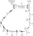
Fig. 1 illustrates an example topology of a smart city system that integrates various field user devices in conjunction with an outdoor lighting network having multiple field devices or spots and communication paths of both.
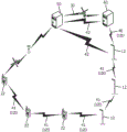
Fig. 2A illustrates the communication topology of the system shown in fig. 1, wherein the primary communication lines of the smart-city system are in failure mode and the outdoor lighting network becomes the D2D access point for the SCS field devices and the OLN CMS remains in contact with the SCS central manager and/or server.
Fig. 2B illustrates the communication topology of the system shown in fig. 1, wherein the primary communication lines of the smart-city system are in failure mode and the outdoor lighting network becomes the D2D access point for the SCS field devices and the OLN CMS is not in contact with the SCS central manager and/or server.
Fig. 3 schematically depicts smart city system elements including a central manager and various field devices.
Fig. 4 schematically depicts an outdoor lighting network element comprising a central manager and various light points/field devices.
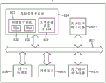
Fig. 5 schematically depicts the architecture of an outdoor lighting system central management system/server.
Fig. 6 schematically depicts the architecture of a smart city system central manager/server.
Fig. 7 is a flow chart illustrating an example method of determining field devices in a smart city system and updating device information and service maps.
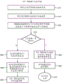
Figure 8 is a flow chart illustrating an example method of managing message and data traffic from an SCS in D2D mode after a primary communication line failure.
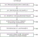
FIG. 9 is a flow chart illustrating an example method of determining field devices in an OLN and updating integrated device information and service maps.
Fig. 10A is a flow chart illustrating an example method of managing message and data traffic in an outdoor lighting network after a primary communication line failure.
Fig. 10B is a flowchart illustrating an example method of managing direct D2D messages in an outdoor lighting network.
Figure 11 is a flow chart illustrating an example method of the SCS user device/field device transitioning to D2D mode during a communication line fault.
Fig. 12 is a flowchart illustrating an example method of an OLN spot transition to D2D mode during a communication line fault.
Fig. 13A schematically depicts an example architecture of an outdoor lighting system central management computer system and server.
Fig. 13B schematically depicts an example architecture of an outdoor lighting system spot or field device.
Detailed Description
Some embodiments of this specification are directed to systems, methods, and apparatus for providing an outdoor lighting network as an emergency communication infrastructure. For standard communication, the OLN spot may be operable to communicate with the management system and with each other in a first mode/protocol. The first protocol has a first message priority method that assigns message priorities according to predetermined criteria (e.g., normal operating conditions), wherein during operation using the first protocol communication method, certain messages have a higher priority for transmission than other messages. The OLN spot may be further operable to communicate with a second (D2D) mode/protocol of operation that provides the ability to relay information and data from non-network sources to destinations through the OLN. The second (D2D) protocol may have a second message priority method that assigns message priorities according to predetermined criteria (e.g., emergency operating conditions), wherein during operation using the second protocol communication method, certain messages have a higher priority for transmission than other messages. This prioritization can also be done dynamically by the OLN central management or the field device for both modes/protocols. Such OLN devices may further be capable of autonomous switching protocols based on defined conditions, or may react to broadcast messages of primary communication line failures in a primary metropolitan area network infrastructure.
Operation of modern systems in buildings and public spaces relies heavily on connections to enable central and supervisory control, remote monitoring, and inter-system/intra-system communication. The connection between the OLN central management entity and the distributed system components, such as light points or field devices, is typically established through wireless networking. In the case of an outdoor lighting network, the connection between the central management system OLN CMS 11 for the outdoor lighting system and the light spots 12 and/or sensors within the OLN may be based on a cellular network (2G, 3G, 4G, 5G, NB-IoT, LTE-eMTC, EC-GSM-IoT) or a wireless mesh network using various peer-to-peer topology standards such as IEEE 802.11, IEEE802.15, IEEE 802.16, and protocols such as ZigBee, ad-hoc on demand, dynamic source routing, etc. The connections between the OLN central management entity and the components of the network may also be outside of standard mesh protocol schemes and include star topologies such as cellular or other ultra-narrow band communication technologies. In the case of the Intelligent Transportation System (ITS) mentioned above in a smart city system, the communication between the traffic center and ITS field devices may use wired (twisted pair, coaxial cable, fiber optic, etc.) or wireless IP-based networks. For ITS and other smart city systems, wireless implementations have become increasingly popular due to deployment flexibility and lower cost.
As shown in fig. 1, an OLN 10 implementation typically has spots or field devices 12 evenly distributed throughout the service area. In this embodiment, each spot may be equipped with D2D technology, making the OLN the network infrastructure of other systems using D2D if the normal network infrastructure fails. The present disclosure exploits this D2D convertibility of OLN spots and sets forth a method for the OLN 10 to act as an emergency network infrastructure for other smart city systems (such as ITS) to preserve necessary services in the event of such communication failure.
The present disclosure utilizes an OLN spot or element 12 that enables device-to-device (D2D) communication as an emergency network infrastructure to provide a communication path for other smart city systems to route critical data through the OLN to a target device or management system when conventional connectivity services are cut off. In essence, OLN 10 becomes another layer that facilitates the resilient (resiience) connectivity of other D2D-capable smart city systems.
As depicted in fig. 1, an OLN 10 is provided, the OLN 10 detailing a plurality of field devices/spots 12, each of which in various embodiments is integrated into a proprietary mesh type network for the OLN or other network communication protocol noted herein. The OLN communication network may be wired or wireless and allows communication between the light spots 12 and the primary control system, the OLN central management system 11 (OLN CMS). The OLN CMS may be a server 60 or other computer with associated processor(s) 818, storage subsystem 824, file storage 826, and memory subsystem 825, as well as other elements, an example of which may include the elements of fig. 13A. OLN CMS 11 controls, monitors and manages a connected outdoor lighting system in which each of the light points/field devices 12 communicates with OLN CMS 11 via a standard network communication mode path 13. The topology of the pathways 13 and implied mesh networks indicated in the figures is merely exemplary, as many other implementations and topologies may be utilized. Under normal operation, the CMS uses the physical network and communication protocols specific to the OLN communication link 13 to exchange data with the OLN field device/spot 12.
In some variations, CMS 11 may establish data exchanges with smart-city system 20 using a center-to-center C2C communication protocol of a dedicated application layer over peer-to-peer network connection 30.
Such dedicated communication channels may be directly integrated with CMS 11 via network interface 816 or other similar architecture. In various embodiments, the C2C link 30 and communication path may be utilized for interconnection and data transfer between the smart city system CM 21 and OLNCMS 11, and in particular for mapping, device location and updating of service network maps. As discussed herein, in various aspects, such a C2C communication connection 30 may also be a transmission path for communication between field devices when in a D2D mode of operation.
Similarly, in fig. 1, a smart city system 20 is depicted, in an embodiment the smart city system 20 may include a central manager 21, an access point, and a plurality of User Equipment (UE) 22. In various embodiments, the smart city system 20 further may optionally include a central manager 21 and, as noted, UE/field devices 22. In one embodiment, the smart city system may be an Intelligent Transportation System (ITS), where the central manager 21 is an ITS center (such as a traffic management center, accident management center, transit management center, guest information center, etc.), and the field devices 22 may be traffic control devices, dynamic message signs, traffic cameras, etc. The C2C communication 30 may include a well-defined information level dictionary (e.g., TMDD), and data may be exchanged at the application layer using web services via extensible markup language (XML) or DATEX ii. In another embodiment, smart city system 20 may include a city emergency alert system in which the central manager is a community emergency management center 21 and field devices 22 may be emergency response vehicles, smart phones subscribing to the system, and the like. In an embodiment, the central manager 21 may consist of a computer system responsible for monitoring, control and management of the smart city system and has the corresponding architectural features as indicated above for use with OLNCMS. Under standard operation, the central manager may establish communications and connections 23 with the field devices UE 22 using network protocols and media specific to the smart city system, and in some embodiments through a WAN or access point as depicted.
In various embodiments, under standard communications, OLN CMS 11 will control various light points and/or sensors 12 via communications channel 13, which communications channel 13 may be wireless and/or wired or a combination thereof. Various features known in outdoor lighting management may be implemented. However, as may be expected, the various light points 12 may be geographically evenly distributed over a city-wide area, and all or some subset may be integrated with the OLN 10 under the control of the OLN CMS 11 or alternative OLN system as depicted. Such spots 12, due to their uniform geographical distribution, may be utilized as D2D communication entry points for an ad-hoc D2D network in some embodiments when a primary communication channel, such as communication network channel 23, fails. Due to the ad-hoc nature of the emergency infrastructure, the OLN CMS may maintain an OLN device service map 150b and an SCS device service map 250b, as shown in fig. 5. The SCS CM and associated network management system may maintain similar service mappings.
As depicted in fig. 4, the outdoor lighting network 10 may include or contain both an OLN CMS 11 and a plurality of OLN devices/light points 12. In some embodiments, OLN CMS 11 may be comprised of smart city system device mapping mechanism 111, smart city message processor 112, normal communication mode 113, and D2D communication mode 114. OLN CMS 11 may communicate with SCS central manager 21 via C2C link 30 for delivery mapping, device and other control, reporting data exchanges, and so forth. Such communication exchanges between servers/management systems and within a smart city system may include a number of operating parameters, and such descriptions are not limited to the embodiments or architectures described herein.
Each of the light spots 12 within the OLN 10 may include a light source, such as an LED or other light generating structure, and further include a processor and associated memory to appropriately control the illumination and communication. Thus, communication ports/paths may be incorporated within the optical spot and include wired or wireless communication to support multiple communication modes. Further, in various embodiments, each of the light points may include instructions stored on the memory and executable by the processor to control illumination of the illumination source and to control messages and communications processed by the light points to other light points, the central management server, and other devices. As discussed herein, such on-board electronics and instructions support message processing and delivery across multiple communication modes and non-OLN devices.
In various embodiments, the smart city system device mapping mechanism 111 of the OLN CMS 11 may geographically associate the smart city field devices 22 with the lighting network service map. Separate OLN database map 150b and SCS device map 250b may be maintained or may be integrated for access by OLN CMS 11. The device and database maps 150b and 250b may be maintained separately, integrated together, or in association at regular intervals. Further, local or primary copies of databases and/or maps may be maintained at off-site locations that may be accessed by each of the subnetworks, depending on the implementation architecture. Information related to the smart city field devices, including device identity, coordinates, functionality, etc., may be obtained from the smart city system central manager 21 through the C2C communication 30 and incorporated into or integrated with the lighting network service map. Using this mapping, the OLN CMS will be able to determine the exact location of a particular smart city device and identify nearby light points or other OLN field devices.
In an embodiment, as depicted in fig. 4, OLN CMS 11 may include normal communication paths 13 to a plurality of OLN spots 12, and may also include switchable D2D communication modes 114 for alternative communication paths to device 12. When in the D2D mode, OLN CMS 11 may communicate via D2D communication path 40 to the OLD spot.
The OLN spot/device 12 may comprise both a normal communication mode 121 and a D2D communication mode 122. When in the D2D communication mode, spot 12 may communicate with SCS field device 22 via communication link 41. In other embodiments discussed herein, spot 12 may further communicate directly with SCS CM via D2D link 42 in DoD communication mode 214, as may be required when in a communication failure state.
Furthermore, and as shown in FIG. 5, the OLN CMS may be linked to multiple devices 12 1 To 12 N . In various other embodiments, the CMS may additionally have an OLN device discovery process 132. The communication line detection process 131, OLN and SCS device mapping mechanism 111, and OLN map associator 132 to associate devices from both OLN and SCS system 20 within the OLN service map.
As will be pointed out hereinafter, the various light points or field devices 12 of the OLN 1 To 12 N Each may have an associated device discovery process that allows each of the light points to discover and detect nearby D2D devices for communication relay while in D2D mode. Such a device detection process allows the OLN field device 12 to locate nearby D2D capable devices and act as a relay of data from them to the associated devices and other nearby devices. Further, the field device 12 of the OLN may autonomously detect and determine a system-wide communication failure by a timeout condition of the communication link 13 or by other means, and may automatically switch from the primary first communication protocol to the secondary D2D protocol.
Similarly, as depicted in one example of the smart city system 20 and SCS CM 21 of fig. 3 and 6, the SCS 20 includes a central manager 21, the central manager 21 having an OLN field device mapping mechanism 211, an OLN message processor 212, a normal communication mode 213, and a D2D communication mode 214. The normal communication mode procedure allows communication between the central manager 21 and the SCS field device 22 via the normal communication mode procedure 221. Likewise, the D2D communication processor 214 allows D2D communication directly between the SCS CM 21 and the OLN spot/device 12 communication mode processor 122 via the communication channel 42. As explained herein, such a direct connection will allow for hop-by-hop communication relay between the SCS field device 22 and the SCS CM 21 via the various components of the OLN lighting network 10 even after a communication system failure of the primary communication pathway. The SCS field device 22 further has a D2D communication mode process 222 that allows communication with the OLN spot 12D 2D communication mode processor 122 to initiate hop-by-hop relay via the OLN 10. These field devices 22 of the SCS may similarly be autonomous in switching from their primary communication network to the D2D network and include device discovery patterns as similarly indicated in the OLN field devices 12.
In the example of FIG. 6, the SCS CM 21 may includeMultiple field devices 22 connected to CM 21 1 To 22 N . The central manager 21 may also include an OLN message processor 212, a field device discovery processor 232, an OLN and SC field device mapping mechanism 211, and SCs&Either one of the OLN map associator 232 may communicate with the OLN map 150a and the SCS device map 250 a. The SCS CM 21 may further include a D2D communication mode processor 214 and a normal communication mode processor 213 and a communication detection processor 231, and the communication detection processor 231 may directly or remotely detect a primary channel communication line failure, thereby initiating a D2D communication mode. The OLN message processor 212 also assigns a message priority to each OLN message based on which communication mode is being used. Each communication mode message priority is based on a further operation mode criterion, e.g. a (first) normal operation mode criterion set or a (second) emergency mode criterion set. Message prioritization for each communication mode may also be accomplished dynamically based on, for example, the number of OLN spots 12 or smart city field devices 22 in operation, nature of the emergency, etc.
In general, and in some embodiments, the features set forth herein may include a center-to-center (C2C) data exchange scheme between OLN CMS 11 and smart city system central manager 21. The system of both SCS CM and OLN CMs provides data exchange of device information and service network map between OLN CMs and other smart city central manager so that device location and service map information can be kept up to date and associated. In some instances, a single OLN device service map 150a and SCS device service map 250a database may be maintained and even integrated. In other alternatives, each central management system may have a copy of their own associated database/map.
The OLN CMS 11 may be further equipped with D2D communication capabilities and may be operable to switch to and from the proprietary OLN communication protocol to D2D mode upon a conventional communication failure. Notification of a primary communication path failure within the smart city system 20 may come directly from the SCS CM 21 via the communication link 30, which notification may then propagate throughout the OLN system via the communication line 13 or via the D2D communication path 42. Also, in various examples, the broadcast status message may propagate communication line status information through the network. Furthermore, in some embodiments, message reply time delay discovery notifications between OLN CMS 11 and SCSCM 21, EU field devices, spots, and/or broadcasters in D2D mode may be utilized as communication state trigger events.
In various aspects, the OLN spot 12 may be equipped with a D2D communication process and/or processor, and may switch to a D2D communication mode upon conventional communication failure and/or receipt of a message of a communication link failure. Further, the smart city system central manager 21 may be equipped with D2D communication capability and may switch to D2D mode upon a conventional communication failure. Further, in some embodiments, the smart city field device 22 is equipped with D2D communication capabilities and may switch to D2D mode upon a conventional communication failure. Thus, the combined outdoor lighting network and smart city system elements described herein may include a D2D communication mechanism (including generic application layer protocols) between the OLN light points 12 and the smart city system field devices 22 to allow the SCS field devices to continue to communicate even after the primary communication path fails. Such functionality may be supported by any communication from field devices via, for example, OLN spot 12 and/or hop-by-hop relay of data to maintain continued and robust communication.
In some embodiments using OLN as emergency connection infrastructure as depicted in fig. 1, the light spots are switched into D2D communication mode. In the scenario shown in fig. 2A, the C2C communication link 30 is unaffected when all other conventional communication networks are switched off. The smart city system central manager may send messages to the OLN CMS using the C2C communication link. The OLN CMS switches to the D2D communication mode and sends a message to the nearest light spot using D2D communication. The message is then relayed between the intermediate pair of light points using D2D communication until it reaches the target D2D capable smart city field device 22. Likewise, backhaul communication may be implemented by transmission of D2D-enabled light points 12 by field devices 22 into an outdoor lighting network. The associated destination and/or address information may be included in the message header for processing by subsequent D2D-capable devices, allowing the transfer of data from the field device 22 to the SCS CM 21 via multiple and now emergency connection infrastructure of the OLN.
In the example of fig. 2B, the C2C communication 30 is also cut off, but the smart city system central manager is able to switch to the D2D communication mode. In this case, the intended message may be sent from the smart city central manager to the nearest light point and/or OLN CM using D2D communication, and then routed through the intermediate light point pair using D2D communication until the target destination smart city field device is reached.
Before any communication line interruption, the SCS CM may have detected all field devices via the field device discovery process 232, in which field devices have been categorized and stored in the SCS device map 250a and associated within the SCS communication network and in some variations, the adjacent OLN network. A similar process may be implemented in the OLN CM with process 132. Such device identifications, mappings, and geographic locations (placements) may be stored in the SCS device map, and associated mapping information may be categorized based on additional information received from neighboring OLN data exchanges. The association data created by the SCS and OLN map associator 232 and OLN and SCS device mapping mechanism can effectively geo-locate the devices and determine their relative locations to each other, to the network and to neighboring D2D-capable networks and determine the appropriate data path. Further, the information created by the correlators may be stored in respective databases 150a and 250a, and in various other embodiments, databases 150a and 250a may be combined. These mapped field devices and networks represented in the database are then available to the SCS CM 21 for message routing in the event of a normal communication mode failure.
Thus, in various embodiments, the OLN field device mapping mechanism 211 geographically associates the OLN field device 12 with a smart city service map, and may store such information in a relational database. Information such as OLN device identity and location may be obtained from OLN CMS 11 through C2C communication 30 and may be incorporated into a smart city system service map. By maintaining not only the up-to-date system map of the SCS field devices and networks, but also the up-to-date system map of the relevant OLN system information (devices and locations), the central manager can geographically associate its field devices 22 with the outdoor lighting network spot 12 in the OLN system 10.
In alternative embodiments, OLN CMS 11 may also utilize OLN and SCS device mapping mechanism 111 and OLN map associator 132 in conjunction with or in the data sharing mode to similarly maintain location awareness of field devices from both SCS and OLN. In various embodiments, the device map 150b/250b for the OLN may be a shared mapping database, may be a shadow mapping database, or may be maintained separately within the OLN CMS with variable frequency data associations between various similar system mappings.
In one example, as depicted in the embodiment of fig. 2A in connection with fig. 1, OLN 10 is provided as an emergency connection infrastructure, wherein light point 12 is switched to a D2D communication mode. In the depicted example, the C2C communication line 30 is unaffected when the normal communication network 23 between the SCS CM 21 and the SCS field device 22 is cut off. The SCS CM may detect such communication disruption via the communication detection procedure 231 and may then relay such information through its network or through a neighboring network of the system. Alternatively, individual devices of any network within the system may autonomously determine such network failure and switch to the D2D communication mode, and similarly switch back to using the normal communication path after the system link active state is identified.
As noted in the above example, the center-to-center primary communication path 30 may be available as depicted, and messages from the SCS CM 21 to the field devices may be routed through the converted OLN 10. In such an embodiment, the SCS field device 22 is effectively removed from communication with the SCS CM 21 due to the failure of the normal communication link 23. In such an embodiment, the smart city system central manager 21 can determine the appropriate route for sending messages to the field devices as a communication path by integrating the OLN system map information with the light points 12. The SCSCM may then send a message to the field device over the outdoor lighting network using the C2C communication channel 30 via the OLN CMS. The smart city message processor 112, upon receiving the message from the SCS CM, can decode data received from the smart city central manager via the C2C communication 30 and encode a message that can be recognized by the OLN device when transmitted to the distributed devices 12 in the D2D mode 114. When transmitting messages between different networks, the messages will need to be identified by both the OLN field device and the SCS field device when transmitted in D2D mode. Thus, in an embodiment, the current system encodes the message through smart city message processor 112 to allow D2D mode message processing via distributed devices 12 such that the hybrid system message is recognized by both OLN field devices 12 and SCS field devices. In an embodiment, message encoding may be required because the last hop of the message will be from the OLN field device to the SCS field device. Alternatively, assuming that the communication path 13 between OLN CMS 11 and device 12 is available, the message may be relayed via normal communication mode 113 to a separate SCS field device 22 through the outdoor lighting network 10. In such an embodiment, even when using a normal OLN communication network link 13, the OLN field device would still need to switch to D2D mode when handing over messages to the SCS field device, such as indicated as communication link 41 in fig. 2A.
Thus, in an embodiment, OLN device/spot 12 may have two communication modes, normal communication mode 121 and D2D communication mode 122. In the normal communication mode 121, devices and networks may utilize OLN-specific network protocols for data exchange with OLN CMS 11. Alternatively, the OLN spot 12 may switch to the D2D communication mode 122, the D2D communication mode 122 may be activated when the normal communication channel 13 is not available or by alternative means such as broadcast messages or instructions from the OLN CMS and/or SCS CM, or other means. Further, the OLN spot 12 may autonomously switch to the D2D communication mode after a conventional connection failure with other OLN spots 12 or with OLN CMS 11 is established in the normal communication mode.
Alternatively, when the field device/spot 12 of the outdoor lighting network 10 is in the D2D communication mode 122, the OLN spot 12 may use a generic application layer protocol to exchange data with any other device within its cellular signal reception range. In one embodiment, the OLN device 12 exchanges data with nearby peer OLN devices using D2D communication. In another embodiment, the OLN device may exchange data directly with the OLN CMS 11 using the D2D communication link 40 when the CMS is within a predetermined communication range. In other aspects, the OLN device 12 is operable to exchange data with a nearby smart city system field device 22 that is also operating in a D2D communication mode via a communication channel 41.
The OLN CMS may determine that the primary communication network for the SCS has failed via broadcast messaging or other data transfer from the SCS CM or other device to the OLN CMS, or upon autonomous determination. When a message is received from the CMS to be delivered to the field device, OLNCMS may switch to D2D communication mode 114 and send the message to the nearest spot using D2D communication mode channel 40. The message may then be relayed between the intermediate pair of light points using D2D communication until it reaches a D2D enabled smart city field device 22 that is operating in a D2D communication mode.
A standard protocol may be used for processing messages by each node/OLN device in D2D mode on a hop-by-hop basis until the message reaches the destination address. Such ad hoc relay of message content or other data may be implemented in a newly formed D2D network formed from an outdoor lighting network, and may be implemented with recipient/destination tagging of the data content such that the message is relayed through the network until received by the recipient/destination.
In some embodiments, OLN CMS 11 may modify the operation of the outdoor lighting network and individual light points or devices 12 after communication failure notification of the smart city system. Such notification may be received by broadcast, unicast, or other methods, or may be embedded within the data exchange between the SCS CM and the OLN CMs. As noted herein, a subsequent notification to a spot or OLN field device 12 that needs to switch to D2D communication mode may be initiated by the OLN CMS or by the SCS CM or other means. Similarly, once the primary communication channel is turned into an operational state, a broadcast or other message may be relayed through the network to return to the primary communication protocol.
In an alternative embodiment, as depicted in fig. 2B, the C2C communication link 30 may be affected. In this example, the C2C communication is cut off, but the smart city system central manager is operable to switch to the D2D communication mode. In such an embodiment, any forwarded message may be sent from the smart city central manager to the nearest OLN spot 12 using D2D communication, which message is then routed through the intermediate spot 12 pair using D2D communication until the target smart city field device is reached.
In various embodiments, the OLN device 12 may implement the D2D communication mode 122 and exchange data along the D2D communication channel 42 to completely bypass the OLN CMS 11 and exchange data with a nearby smart city system central manager 21, which nearby smart city system central manager 21 may operate in the D2D communication mode 214 with the same application layer protocol.
In connection with an outdoor lighting network and in various embodiments, the smart city system central manager 21 may include an OLN field device mapping mechanism 211, an OLN message processor 212, a normal communication mode 213, and an optional D2D communication mode 214.
The OLN field device mapping mechanism 211 depicted in fig. 3 may operate in various embodiments to geographically associate a wide variety of OLN points/field devices 12 with a smart city service map. Information such as OLN device identities of a plurality of devices may be obtained from OLN CMS 11 through C2C communication 30 and incorporated into a smart city service map. The SCS central manager is thus operable to geographically associate its field device 22 with the spot 12 in the OLN system 10 and to identify the extent (existence) of various networks adjacent to the SCS field device 22.
Further and additionally, for embodiments of the smart city system CM 21, the OLN message processor 212 may contain two capabilities depending on the routing of the message. In a first aspect, the OLN message processor 212 may decode data received from the OLN CMS 11 over the C2C communication protocol 30 in normal operation for use in the OLN field device mapping mechanism 211. Information and other relevant data received from OLN CMS 11 about OLN's devices 12 may be geographically associated and mapped in relation to SCS networks and devices and maintained for quick reference. Further, the message processor 212 may be operable to encode a message to be forwarded to the smart city field device 22 via the outdoor lighting network via the D2D communication path 42 in a format that is recognizable by the OLN device 12 when directly transmitted to the OLN device 12 in the D2D mode 214. Thus and as a result of this operability, when the SCS CM 21 experiences a connection failure using the normal communication mode 213, the D2D communication mode 214 can be activated, and the OLN network of spots provides an emergency connection infrastructure using switchable D2D communication capabilities.
In another aspect of the SCS CM 21, when the normal communication channel 23 is cut off but the C2C communication channel 30 is intact, the central manager may be operable to communicate a message to the intended SCS target field device over the OLN CMs 11 over the C2C communication link 30. Messages can then be routed hop-by-hop from OLN CMS 11 through intermediate OLN device 12 to the target smart city field device using D2D communications 40, 41 between the OLN device/spot 12 pairs.
In another embodiment, when both the normal communication mode channel 23 and the C2C communication channel 30 are cut off and the central manager 21 is capable of D2D communication, the central manager itself can switch to the D2D communication mode 214 for direct communication with the reconfigured OLN field device 12. The OLN message processor 212 may then encode the message to the intended field device in a format recognizable by the OLN device at the D2D communication application layer and send the message to the nearby OLN device 12 using the D2D communication channel 42. The message may then be routed through a series of intermediate OLN devices 12 using D2D communications 42, 41 until it reaches the intended SCS target field device 22. In such an embodiment, smart city field device 22 may have two communication modes, a normal communication mode 221 and a D2D communication mode 222. In some embodiments, the normal communication mode 221 may use a network protocol specific to the smart city system for data exchange with the central manager 21. Further, the D2D communication mode 222 of the SCS field device 22 can be autonomously activated by the field device 22 itself upon detecting a shutdown in the normal communication channel 23. The D2D communication mode 222 is thus operable to enable the field device to exchange data with other entities within its cellular signal range using a common application layer protocol. As noted, such other devices include switchable outdoor lighting network field devices that can both communicate in a standard communication mode 121 via channel 12 and also switch to a D2D communication mode 122 depending on the destination usage channel 40/41/42. Of course, the various channels may be a single channel and use a single application layer, but are shown separately in an attempt to indicate separate communication paths for the various embodiments. Also, various other communication channels may be shown separately in the drawings, but may in fact include the same or different communication configurations, protocols, or application layers in the use and operation of the OLN field device and OLN CMS. The so-called application layer is intended to include an abstraction layer that specifies the generic protocols and interface methods used by hosts and other devices in a communication network.
In some embodiments, as illustrated in detail in fig. 7, the SCS CM may have a memory with instructions stored thereon to implement the various methods and features described and implemented by execution on a processor. As detailed in the illustrated example, the SCS CM 21 may identify the field devices 22 within its network detectable region at step 550. The SCS CM may further geo-locate the SCS field device 22 at step 552 and then update the SCS device map and service network map located within the SCS device map database 250a at step 554. Similar databases may be maintained at the peripheral network (such as outdoor lighting network 10 database 250 b), and such databases may be routinely associated via data exchanges. Utilizing a decentralized data set may allow each management system to autonomously detect and update a corresponding map and to geolocate a group (location) of field devices within a service area.
At step 558, various peripheral networks, such as the outdoor lighting network 10, may be identified, and associated communications via the C2C communications 30 may occur between two servers handling management functions of the various networks. At step 562, any identified outdoor lighting networks may be associated and classified and, in some examples, positioned relative to the SCS network. Finally, at step 564, the data obtained by the SCS CM may be exchanged with the OLN CMs so that both maps may be associated, updated and maintained.
As depicted in the embodiment for data transfer of the SCS CM to the external network as depicted in fig. 8, the SCS CM may be operable to utilize the converted OLN system and network as an infrastructure for emergency connection during network failure.
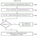
In an embodiment, at step 572, the SCS CM may receive a message for processing within the SCS network 20 at step 572. For example, at step 574, the SCS CM may determine a communication network or system failure of the primary communication network 23 to the field device 22 by a timeout communication clock or via status messaging. At step 578, the central manager may determine whether the C2C communication line 30 is active and, if so, continue to transmit messages via the links to the OLN CM via the message in the appropriate addressing route. Such data and message traffic routed via OLN 10 may have appropriate addressing headers and information so that OLN CMS may properly redirect messages to SCS field devices via D2D transport layers within the OLN.
In an embodiment, as depicted in fig. 8, SCS CM data transfer may occur between the SCS CM and the external network. In various embodiments, the smart city system central manager 21 may have data or messages to be passed to the SCS field device 22 that is currently disconnected from the SCS network due to a network failure or shutdown as depicted in fig. 2A and 2B. In an option, the SCS CM may determine that a message needs to be sent to the SCS field device 22, as depicted at step 572. Once the smart city system central manager 21 has determined the message and the appropriate field device identifier, the SCS CM can determine that the communication system is currently in failure mode and that the communication link 23 is out of operation. As noted, the SCS CM 21 has a communication detection process 231, and the communication detection process 231 can determine that a communication failure already exists as indicated at step 574. Next, in some applications, the SCS CM may determine that the outdoor lighting network location immediately adjacent to the destination field device 22 is the relevant target and connection infrastructure based on the service map 250A/150A, and may then determine and calculate a communication path to the field device 22. The SCS CM may then determine whether the C2C communication link 30 is active, and if so, the smart-city system central manager 21 may forward the message of the communication failure and the communication failure status to the outdoor lighting network CMs 11 via the C2C path 30 at step 580, which will then switch the outdoor lighting network CMs and the various field devices 12 to the D2D communication mode as indicated at step 582, after which the OLN message processing service 672 may begin.
Alternatively, in some embodiments, the inactive C2C pathway may cause the SCS CM 21 to send data to the OLN network via the D2D communication mode 214 at step 586. The OLN message processor 212 may then encode an outbound (outbound) message to the field device in D2D mode at step 588, and the SCS CM may transmit to the OLN device 12 via D2D mode and communication link 42 at step 590.
As outlined in fig. 9, an exemplary flowchart of an outdoor lighting network system and field device update is provided. In some embodiments, the OLN CMS may identify the field device 12 via the device discovery process 132 at step 650. Next, the OLN CMS may further geo-locate the field devices 12 within the network map at step 652, and then the OLN CMS may update the OLN CMS device map and service network map 150B/250B with the relevant information at step 654. OLNCMS 11 may further geographically associate SCS field device 22 received from the SCS CM via C2C communication 30 at step 658 and then incorporate SCS field device 22 into the OLN network map at step 660. Finally, in some embodiments, at step 662, the data may be exchanged and updated with the SCS CM via the communication link C2C 30, the data including device information data and service network map information.
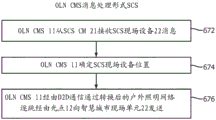
The OLN CMS 11 may optionally have a message processing procedure for receiving a message from the smart city system central manager 21 as depicted in fig. 10A. In some embodiments, such a process may include, at step 672, OLN CMS 11 receiving SCS field device messages or data from the SCSCM, and in response thereto, OLN CMS may determine SCS field device locations from various databases and maps 150B/250B currently available to OLN CMS. As noted, these field device maps and OLN device maps may be associated, combined, or maintained at a remote location in conjunction with the smart city system central manager 21 device map. Finally, as depicted in fig. 2A, at step 676, OLN CMS 11 may transmit hop-by-hop over the converted outdoor lighting network via D2D communication to SCS field device 22 via field device unit 12.
As shown in the flowchart of fig. 10B, the outdoor lighting network utilized as an emergency connection infrastructure may also implement message processing through individual light points received directly from the SCS network, and specifically from the SCS CM 21 or individual field devices 22. Initially, at step 680, the OLN spot or field device 12 may receive a message from the SCS field device 22. The message or data may include destination or other routing information attached to the message or data for processing by a separate light spot in the OLN.
The OLN spot or field device 12 then redirects the received SCS field device 22 message to the adjacent spot 12 via the OLN network 10 over a device-to-device communication link. At step 684, OLN CMS 11 may ultimately receive the rerouted message for routing directly to the SCS CM at step 684.
The origination message from the SCS network may also be routed through multiple SCS field devices 22 by hop-by-hop or relay communication all through the D2D communication protocol by means of each of the field devices discovering nearby field devices.
At step 688, once the OLN CMS 11 receives the message for routing, a determination will be made as to whether a C2C path is feasible. If a C2C communication link is available, the OLN CMS will forward the message to the SCS CM 21 via the C2C path 30 at step 690. Alternatively, if the C2C path is not available, the OLN CMS 11 may instruct the spot or field device to transmit directly using D2D protocols via a D2D relay from the OLN infrastructure directly to the SCS CM 21. In alternative embodiments, the OLN CMS may have D2D communication capabilities to bypass the C2C communication link 30 and possibly transmit directly through D2D communication. However, given the width and extent of geographic displacement of the OLN field units and/or spots, it is possible that individual spots within the OLN will be available in such instances for direct transmission to the SCS CM, the OLN CMs may direct the individual spots to redirect any messages routed to the SCS CM via alternative pathways and bypass the OLM CMs.
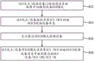
As depicted in fig. 12, the OLN spot may be operable to detect a communication system failure and autonomously switch from a primary protocol to a secondary D2D protocol. At step 852, the OLN spot 12 may detect such a communication failure and switch to the D2D communication mode. At step 854, the OLN spot may receive SCS field device messages from a neighboring field device 22 outside of the outdoor lighting network, but wherein the field device outside of the network causes itself to switch to D2D communication mode. At step 856, the OLN device 12 may similarly discover neighboring or nearby D2D-enabled light points for transmission of the message and its relay. Finally, at step 858, the OLN spot may relay SCS field device messages, which may include SCS CM destinations, that occur at the nearest OLN field device and/or D2D enabled device for transmission of destination addresses.
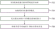
Alternatively, as depicted in fig. 11, a similar switching of device detection and communication protocols is shown for field device 22. At step 752, the SCS field device 22 may autonomously or through broadcast communication or otherwise detect a conventional communication cut-off. At step 754, the field device 22 may switch to the D2D mode, and at step 756, the device may locate the nearest field device 12 that supports the D2D mode through a discovery process. After such discovery of neighboring OLN field devices, the SCS field device 22 can transmit data or messages with appropriate destination and address information to devices outside the network for relay or hop-by-hop transmission and D2D protocols. As can be appreciated, the relay through the D2D communication protocol may occur within the network, outside the network, or across the network, as long as appropriate addressing information is provided, which is why embodiments with such widely geographically dispersed outdoor lighting networks are beneficial as emergency communication networks.
As shown in fig. 13A, an exemplary schematic diagram of an OLN management system server is depicted, including a storage subsystem 824, a memory subsystem 825, which memory subsystem 825 may include ROM 832 and RAM 830. Storage subsystem 824 may also include file storage subsystem 826. Bus 812 may connect the storage subsystem with various processors 818 and network interface 816, which network interface 816 may include different communication protocol transmitters for both the communication protocol link for OLN 13 and C2C communication link 30. In a further embodiment, the network interface may also provide communication in D2D mode as depicted in fig. 2B for communication in such a device-to-device protocol between the server and the light point and other communication endpoints. Further, a user interface and output device 820 may be provided for inclusion and user interface. The schematic diagram of fig. 13A is merely depicted as an example of an implementation of a management system server of an outdoor lighting network or a smart city system network CM server, and none of them need necessarily include each of the sub-elements indicated therein.
As shown in fig. 13B, an exemplary schematic diagram of an OLN spot or field device 12 is depicted, which includes a storage subsystem 924, a memory subsystem 925, which memory subsystem 925 may include ROM 932 and RAM 930. Storage subsystem 924 may also include file storage subsystem 926. An intermediate connection bus 912 may connect the storage subsystem to various processors 914 and network interfaces 916, which network interfaces 916 may include both first and second communication protocol transmitters and the required communication electronics. In various embodiments of the illumination source, the light spot may further comprise sensing and detection mechanisms as well as various control hardware and software. The illumination output source 940 may be broad area illumination, street lighting, floodlight or wall wash illumination, or any other desired outdoor illumination, and may include corresponding illumination or illumination controls 922, where the illumination or illumination controls 922 may be in communication with associated storage subsystems and/or processors as desired. The controller may also be implemented by the processor 914 or may have a separate light controller for each illumination source (such as an LED) or for groups of illumination sources. The schematic diagram of fig. 13B is depicted merely as an example of an implementation of the various light points and field devices of an outdoor lighting network or a smart city system network, and none of them need necessarily include each of the sub-elements indicated therein.
As depicted, a field device may contain the utilization of a memory subsystem and a file storage subsystem, but need not include all or both. Further, the network interface may include support from the memory subsystem for various communication protocols for the underlying outdoor lighting network or the underlying smart city system network. Such protocols may also include alternative D2D protocols for each of the fully supported implementations, as well as instructions stored in a memory subsystem that may be executed by a processor to implement the various functional elements and aspects described herein.
Although several embodiments have been described and illustrated herein, a person of ordinary skill in the art will readily envision a variety of other means and/or structures for performing the functions and/or obtaining the results and/or one or more of the advantages described herein, and each of such variations and/or modifications is deemed to be within the scope of the embodiments described herein. More generally, those skilled in the art will readily recognize that all parameters, dimensions, materials, and configurations described herein are meant to be exemplary and that the actual parameters, dimensions, materials, and/or configurations will depend upon the specific application or applications for which the technology is/are used. Those skilled in the art will recognize, or be able to ascertain using no more than routine experimentation, many equivalents to the specific embodiments described herein. It is, therefore, to be understood that the foregoing embodiments are presented by way of example only and that, within the scope of the appended claims and equivalents thereto, the embodiments may be practiced otherwise than as specifically described and claimed. Embodiments of the present disclosure relate to each individual feature, system, article, material, kit, and/or method described herein. In addition, if such features, systems, articles, materials, kits, and/or methods are not mutually inconsistent, any combination of two or more such features, systems, articles, materials, kits, and/or methods is included within the scope of the present disclosure.
All definitions, as defined and used herein, should be understood to control dictionary definitions, definitions in documents incorporated by reference, and/or ordinary meanings of the defined terms.
The indefinite articles "a" and "an" as used herein in the specification and claims should be understood to mean "at least one" unless explicitly indicated to the contrary.
The phrase "and/or" as used herein in the specification and claims should be understood to mean "either or both" of the elements so combined (i.e., elements that are in some cases combined and in other cases separated). The various elements listed with "and/or" should be interpreted in the same manner, i.e., "one or more" of the elements so combined. In addition to elements specifically identified by the "and/or" clause, other elements may optionally be present, whether related or unrelated to those elements specifically identified. Thus, as a non-limiting example, when used in conjunction with an open language such as "comprising," references to "a and/or B" may refer in one embodiment to a (optionally including elements other than B) only; in another embodiment, it may refer to B only (optionally including elements other than a); in yet another embodiment, it may refer to both a and B (optionally including other elements), and so forth.
As used herein in the specification and claims, "or" should be understood to have the same meaning as "and/or" as defined above. For example, when items in a list are separated, "or" and/or "should be construed as inclusive, i.e., including at least one of a plurality of elements or lists of elements, but also including more than one of a plurality of elements or lists of elements, and optionally additional unlisted items. Only terms explicitly indicated to the contrary, such as "only one of … …" or exactly one of … … ", or, when used in the claims," consisting of "will refer to comprising a plurality of elements or exactly one element of a list of elements. In general, the term "or" as used herein, when preceded by an exclusive term (such as "either," "one of … …," "only one of … …," or "exactly one of … …"), should only be construed as indicating an exclusive alternative (i.e., "one or the other but not both"). "consisting essentially of..once used in the claims shall have its ordinary meaning as used in the patent laws.
As used herein in the specification and claims, the phrase "at least one" with respect to a list of one or more elements should be understood to mean at least one element selected from any one or more of the elements in the list of elements, but does not necessarily include at least one element of each element specifically listed within the list of elements, and does not exclude any combination of elements in the list of elements. The definition also allows that elements may optionally be present in addition to elements specifically identified within the list of elements to which the phrase "at least one" refers, whether related or unrelated to those elements specifically identified. Thus, as a non-limiting example, "at least one of a and B" (or equivalently, "at least one of a or B," or equivalently, "at least one of a and/or B") may refer in one embodiment to at least one a, optionally including more than one a, wherein B is absent (and optionally including elements other than B); in another embodiment, it may refer to at least one B, optionally including more than one B, wherein a is absent (and optionally including elements other than a); in yet another embodiment, it may refer to at least one a, optionally including more than one a, and at least one B, optionally including more than one B (and optionally including other elements), and so forth.
It should also be understood that, unless explicitly indicated to the contrary, in any method claimed herein that includes more than one step or action, the order of the steps or actions of a method is not necessarily limited to the order of the steps or actions of the method as recited.
In the claims and the above description, all transitional phrases such as "comprising," "including," "carrying," "having," "containing," "involving," "holding," "containing," and the like are to be construed as open-ended, i.e., to mean including but not limited to. Only the transitional phrases "consisting of" and "consisting essentially of" shall be closed or semi-closed transitional phrases, respectively, as described in section 2111.03 of the U.S. patent office patent review program manual. It should be understood that certain expressions and reference numerals used in the claims in accordance with rule 6.2 (b) of the patent cooperation treaty ("PCT") do not limit the scope.
Claims (14)
1. An outdoor lighting system for use as an emergency connection infrastructure, comprising:
an outdoor lighting network management system (11) in communication with a plurality of light points (12) forming an outdoor lighting network (10), each of the plurality of light points emitting illumination and in communication with other light points and the outdoor lighting network management system through a first communication protocol (13) having a first message prioritization method, wherein the outdoor lighting system assigns message priorities according to a first predetermined criterion;
Wherein each of the light points in the outdoor lighting network has instructions stored in memory and has a processor to execute the instructions to:
switching the light spots to a second communication protocol (40), the second communication protocol being a device-to-device protocol, wherein each of the light spots is operable to transmit messages to geographically adjacent light spots in the outdoor lighting network, the second communication protocol having a second message prioritization method, wherein the outdoor lighting system assigns message priorities according to a second predetermined criterion;
further wherein each of the light points in the outdoor lighting network has instructions to communicate with a field device (22) of a separate system network (20) through the second communication protocol, the separate system network (20) not being associated with the outdoor lighting network;
wherein the second communication protocol is a device-to-device (D2D) cellular communication protocol;
and wherein each of the outdoor lighting network light points is operable to autonomously switch between the first communication protocol and the second communication protocol.
2. The outdoor lighting system of claim 1, wherein the outdoor lighting network management system has instructions stored in memory and has a processor to execute the instructions to: -communicate with the plurality of light spots of the outdoor lighting network in the first communication protocol in a normal communication mode (121), and with the plurality of light spots in the second communication protocol in a device-to-device communication mode (122).
3. The outdoor lighting system of claim 2, wherein the outdoor lighting network management system comprises a message processor (112) operable to receive messages from the separate system network (20) and decode the received messages, and further encode messages to be identified by the plurality of light points when communicating in the device-to-device communication mode.
4. An outdoor lighting system according to claim 3, wherein the outdoor lighting network management system comprises a device and mapping mechanism (111), the device and mapping mechanism (111) being operable to geographically associate a plurality of field devices (22) from the separate system network with a lighting network service map.
5. The outdoor lighting system of claim 4, wherein the outdoor lighting network management system further comprises a map correlator (132) to correlate the lighting network service map with a service map from the separate system network.
6. The outdoor lighting system of claim 1, wherein the outdoor lighting network management system is part of a larger computer network defining a smart city system having a manager server (50) in communication with a plurality of smart city systems, the outdoor lighting network being one of the plurality of smart city systems.
7. The outdoor lighting system of claim 6, wherein the smart city system further comprises a plurality of distributed system components, at least one of the distributed system components being a plurality of smart city field devices, at least one of the smart city field devices comprising a field device of the separate system network.
8. The outdoor lighting system of claim 1, wherein the outdoor lighting network spots are each operable to enter a discovery mode, wherein the discovery mode discovers nearby devices that are either adjacent outdoor lighting network spots (12) or field devices (22) of the separate system network.
9. The outdoor lighting system of claim 6, wherein the first communication protocol is a proprietary outdoor lighting network communication protocol.
10. The outdoor lighting system of claim 9, wherein the outdoor lighting network spot communicates in the second communication protocol and transmits data through a plurality of devices until the data reaches a destination.
11. The outdoor lighting system of claim 10, wherein the outdoor lighting network spots comprise instructions to implement a dynamic routing algorithm to allow each outdoor lighting network spot to include routing information in the transmitted data.
12. The outdoor lighting system of claim 6, wherein the first communication protocol is a cellular-based protocol.
13. The outdoor lighting system of claim 12, wherein the first communication protocol is a mesh-based protocol.
14. A method for an off-user lighting network to provide emergency connection infrastructure, comprising:
forming an outdoor lighting network (10) having a plurality of light points (12);
communicating between the plurality of light points (12) and a lighting network management system (11) in a first communication protocol having a first message prioritization method, wherein the outdoor lighting network assigns message priorities according to a first predetermined criterion;
switching the plurality of light spots from the first communication protocol (13) to a second communication protocol (40), the second communication protocol being a proximity device-to-device communication protocol, the second communication protocol having a second message prioritization method, wherein the outdoor lighting network assigns message priorities according to a second predetermined criterion;
receiving (672), by one of the light spots, a data stream from the outdoor lighting network comprising a destination address, the destination address being external to the outdoor lighting network, the data stream being transmitted by a device external to the outdoor lighting network;
Transmitting (676) the data stream by the receiving light spot in the outdoor lighting network in the second communication protocol to a neighboring receiving device, the neighboring receiving device being one of the plurality of light spots from the outdoor lighting network or the light spot
An external device external to the outdoor lighting network;
wherein switching between the first communication protocol to the second communication protocol by the plurality of light spots is done autonomously.
Applications Claiming Priority (5)
| Application Number | Priority Date | Filing Date | Title |
|---|---|---|---|
| US201662380738P | 2016-08-29 | 2016-08-29 | |
| US62/380738 | 2016-08-29 | ||
| EP16190074 | 2016-09-22 | ||
| EP16190074.1 | 2016-09-22 | ||
| PCT/EP2017/071130 WO2018041669A1 (en) | 2016-08-29 | 2017-08-22 | Outdoor lighting network as a contingency connectivity infrastructure |
Publications (2)
| Publication Number | Publication Date |
|---|---|
| CN109716823A CN109716823A (en) | 2019-05-03 |
| CN109716823B true CN109716823B (en) | 2023-06-27 |
Family
ID=59738321
Family Applications (1)
| Application Number | Title | Priority Date | Filing Date |
|---|---|---|---|
| CN201780053505.6A Active CN109716823B (en) | 2016-08-29 | 2017-08-22 | Outdoor lighting network as an emergency connection infrastructure |
Country Status (3)
| Country | Link |
|---|---|
| EP (1) | EP3504902B1 (en) |
| JP (1) | JP6967581B2 (en) |
| CN (1) | CN109716823B (en) |
Families Citing this family (4)
| Publication number | Priority date | Publication date | Assignee | Title |
|---|---|---|---|---|
| JP7392549B2 (en) | 2020-03-31 | 2023-12-06 | 東芝ライテック株式会社 | Control device |
| CN112215564A (en) * | 2020-09-04 | 2021-01-12 | 杭州运河集团文化旅游有限公司 | Intelligent fire-fighting emergency management system and method thereof |
| CN116938689A (en) * | 2022-04-01 | 2023-10-24 | 中兴通讯股份有限公司 | Network switching method, node, electronic device, and readable storage medium |
| CN115776752B (en) * | 2023-02-13 | 2023-08-04 | 佛山市银河兰晶科技股份有限公司 | Control circuit, lamp and control method based on ZigBee protocol |
Citations (7)
| Publication number | Priority date | Publication date | Assignee | Title |
|---|---|---|---|---|
| CN101563957A (en) * | 2006-12-20 | 2009-10-21 | 皇家飞利浦电子股份有限公司 | Method and system to select devices of a wireless network, particularly a network of wireless lighting devices |
| CN102448217A (en) * | 2011-06-28 | 2012-05-09 | 于佳辉 | Municipal lighting control system and method based on Internet of things |
| WO2014047907A1 (en) * | 2012-09-28 | 2014-04-03 | Telefonaktiebolaget L M Ericsson(Publ) | Method for d2d radiocommunication |
| WO2015129305A1 (en) * | 2014-02-26 | 2015-09-03 | シャープ株式会社 | Portable terminal apparatus |
| CN105247799A (en) * | 2013-05-21 | 2016-01-13 | 瑞典爱立信有限公司 | Preventative maintenance by detecting lifetime of components |
| CN105493616A (en) * | 2013-09-26 | 2016-04-13 | 英特尔Ip公司 | User equipment and protocol and methods for device-to-device communication |
| CN105824299A (en) * | 2016-03-15 | 2016-08-03 | 浙江创意声光电科技有限公司 | City-level smart illumination control management system and control method thereof |
Family Cites Families (6)
| Publication number | Priority date | Publication date | Assignee | Title |
|---|---|---|---|---|
| US8588830B2 (en) * | 2007-02-02 | 2013-11-19 | Inovus Solar, Inc | Wireless autonomous solar-powered outdoor lighting and energy and information management network |
| WO2014174412A2 (en) * | 2013-04-25 | 2014-10-30 | Koninklijke Philips N.V. | Adaptive outdoor lighting control system based on user behavior |
| US9497836B2 (en) * | 2013-06-04 | 2016-11-15 | Koninklijke Philips N.V. | Lighting system for illuminating an environment and a method of starting an installation of a program on a programmable controller |
| CN105359627B (en) * | 2013-07-05 | 2018-08-17 | 飞利浦灯具控股公司 | For operating the method for communication equipment, communication equipment, the luminaire equipped with such communication equipment in a communication network |
| KR20160017627A (en) * | 2014-08-06 | 2016-02-16 | 삼성전자주식회사 | Apparatus and method for transmitting and receiving signals of device-to-device terminal |
| CN110087312B (en) * | 2014-09-25 | 2023-10-24 | 株式会社Ntt都科摩 | Terminal and communication method |
-
2017
- 2017-08-22 EP EP17758485.1A patent/EP3504902B1/en active Active
- 2017-08-22 JP JP2019511757A patent/JP6967581B2/en active Active
- 2017-08-22 CN CN201780053505.6A patent/CN109716823B/en active Active
Patent Citations (7)
| Publication number | Priority date | Publication date | Assignee | Title |
|---|---|---|---|---|
| CN101563957A (en) * | 2006-12-20 | 2009-10-21 | 皇家飞利浦电子股份有限公司 | Method and system to select devices of a wireless network, particularly a network of wireless lighting devices |
| CN102448217A (en) * | 2011-06-28 | 2012-05-09 | 于佳辉 | Municipal lighting control system and method based on Internet of things |
| WO2014047907A1 (en) * | 2012-09-28 | 2014-04-03 | Telefonaktiebolaget L M Ericsson(Publ) | Method for d2d radiocommunication |
| CN105247799A (en) * | 2013-05-21 | 2016-01-13 | 瑞典爱立信有限公司 | Preventative maintenance by detecting lifetime of components |
| CN105493616A (en) * | 2013-09-26 | 2016-04-13 | 英特尔Ip公司 | User equipment and protocol and methods for device-to-device communication |
| WO2015129305A1 (en) * | 2014-02-26 | 2015-09-03 | シャープ株式会社 | Portable terminal apparatus |
| CN105824299A (en) * | 2016-03-15 | 2016-08-03 | 浙江创意声光电科技有限公司 | City-level smart illumination control management system and control method thereof |
Also Published As
| Publication number | Publication date |
|---|---|
| JP2019532561A (en) | 2019-11-07 |
| CN109716823A (en) | 2019-05-03 |
| JP6967581B2 (en) | 2021-11-17 |
| EP3504902B1 (en) | 2021-08-11 |
| EP3504902A1 (en) | 2019-07-03 |
Similar Documents
| Publication | Publication Date | Title |
|---|---|---|
| US11197177B2 (en) | Outdoor lighting network as a contingency connectivity infrastructure | |
| CN109716823B (en) | Outdoor lighting network as an emergency connection infrastructure | |
| CN101883048B (en) | Routing method of multi-dimensional network | |
| US9648662B2 (en) | Bluetooth networking | |
| CN102202333B (en) | Routing method of wireless ad hoc network used for small satellite constellation communication | |
| US8503349B2 (en) | Wireless LAN relay apparatus | |
| CN103281247B (en) | The general method for routing of a kind of data center network and system | |
| CN102334312B (en) | For the formation of, safeguard and/or use the method and apparatus of crossover network | |
| CN104283774B (en) | The implementation method and device in a kind of AC ponds | |
| CN104144124B (en) | Data forwarding method, Apparatus and system | |
| Stefanović et al. | Urban infrastructure-to-vehicle traffic data dissemination using UEP rateless codes | |
| CN102780615A (en) | Link backup method and routing forwarding device | |
| US8228847B2 (en) | Multihop radio hazard reporting system | |
| US20100165831A1 (en) | Load balancing and fault protection in aggregation networks | |
| US9735859B1 (en) | Method and apparatus for distributing addresses of communication devices within a satellite network | |
| US9325606B2 (en) | Communication system, communication route control method, and communication apparatus | |
| CN110493733A (en) | A kind of Mesh network system based on Bluetooth Low Energy mobile device | |
| JP2013046090A (en) | Communication device and communication system | |
| Inoue et al. | NerveNet architecture and its pilot test in Shirahama for resilient social infrastructure | |
| CN105357674A (en) | Data distribution method, device and system | |
| JP2006019796A (en) | Wireless routing system and street light fault monitor system utilizing this system | |
| WO2014079061A1 (en) | Signalling processing method, device and system | |
| Demers et al. | Scalable registration and discovery of devices in low-bandwidth tactical networks | |
| CN113810911B (en) | Novel integrated base station self-organizing network system and method based on 5G | |
| CN116321344A (en) | Hybrid ad hoc network system and method |
Legal Events
| Date | Code | Title | Description |
|---|---|---|---|
| PB01 | Publication | ||
| PB01 | Publication | ||
| SE01 | Entry into force of request for substantive examination | ||
| SE01 | Entry into force of request for substantive examination | ||
| GR01 | Patent grant | ||
| GR01 | Patent grant |