JP6966533B2 - Ionic touch panel - Google Patents
Ionic touch panel Download PDFInfo
- Publication number
- JP6966533B2 JP6966533B2 JP2019503251A JP2019503251A JP6966533B2 JP 6966533 B2 JP6966533 B2 JP 6966533B2 JP 2019503251 A JP2019503251 A JP 2019503251A JP 2019503251 A JP2019503251 A JP 2019503251A JP 6966533 B2 JP6966533 B2 JP 6966533B2
- Authority
- JP
- Japan
- Prior art keywords
- touch
- hydrogel
- ionic
- touch panel
- current
- Prior art date
- Legal status (The legal status is an assumption and is not a legal conclusion. Google has not performed a legal analysis and makes no representation as to the accuracy of the status listed.)
- Active
Links
Images


Classifications
-
- G—PHYSICS
- G06—COMPUTING; CALCULATING OR COUNTING
- G06F—ELECTRIC DIGITAL DATA PROCESSING
- G06F3/00—Input arrangements for transferring data to be processed into a form capable of being handled by the computer; Output arrangements for transferring data from processing unit to output unit, e.g. interface arrangements
- G06F3/01—Input arrangements or combined input and output arrangements for interaction between user and computer
- G06F3/03—Arrangements for converting the position or the displacement of a member into a coded form
- G06F3/041—Digitisers, e.g. for touch screens or touch pads, characterised by the transducing means
- G06F3/044—Digitisers, e.g. for touch screens or touch pads, characterised by the transducing means by capacitive means
-
- G—PHYSICS
- G01—MEASURING; TESTING
- G01N—INVESTIGATING OR ANALYSING MATERIALS BY DETERMINING THEIR CHEMICAL OR PHYSICAL PROPERTIES
- G01N27/00—Investigating or analysing materials by the use of electric, electrochemical, or magnetic means
- G01N27/26—Investigating or analysing materials by the use of electric, electrochemical, or magnetic means by investigating electrochemical variables; by using electrolysis or electrophoresis
- G01N27/28—Electrolytic cell components
- G01N27/30—Electrodes, e.g. test electrodes; Half-cells
- G01N27/333—Ion-selective electrodes or membranes
- G01N27/3335—Ion-selective electrodes or membranes the membrane containing at least one organic component
-
- G—PHYSICS
- G06—COMPUTING; CALCULATING OR COUNTING
- G06F—ELECTRIC DIGITAL DATA PROCESSING
- G06F3/00—Input arrangements for transferring data to be processed into a form capable of being handled by the computer; Output arrangements for transferring data from processing unit to output unit, e.g. interface arrangements
- G06F3/01—Input arrangements or combined input and output arrangements for interaction between user and computer
- G06F3/03—Arrangements for converting the position or the displacement of a member into a coded form
- G06F3/041—Digitisers, e.g. for touch screens or touch pads, characterised by the transducing means
- G06F3/0412—Digitisers structurally integrated in a display
-
- G—PHYSICS
- G06—COMPUTING; CALCULATING OR COUNTING
- G06F—ELECTRIC DIGITAL DATA PROCESSING
- G06F3/00—Input arrangements for transferring data to be processed into a form capable of being handled by the computer; Output arrangements for transferring data from processing unit to output unit, e.g. interface arrangements
- G06F3/01—Input arrangements or combined input and output arrangements for interaction between user and computer
- G06F3/03—Arrangements for converting the position or the displacement of a member into a coded form
- G06F3/041—Digitisers, e.g. for touch screens or touch pads, characterised by the transducing means
- G06F3/0416—Control or interface arrangements specially adapted for digitisers
-
- G—PHYSICS
- G06—COMPUTING; CALCULATING OR COUNTING
- G06F—ELECTRIC DIGITAL DATA PROCESSING
- G06F3/00—Input arrangements for transferring data to be processed into a form capable of being handled by the computer; Output arrangements for transferring data from processing unit to output unit, e.g. interface arrangements
- G06F3/01—Input arrangements or combined input and output arrangements for interaction between user and computer
- G06F3/03—Arrangements for converting the position or the displacement of a member into a coded form
- G06F3/041—Digitisers, e.g. for touch screens or touch pads, characterised by the transducing means
- G06F3/045—Digitisers, e.g. for touch screens or touch pads, characterised by the transducing means using resistive elements, e.g. a single continuous surface or two parallel surfaces put in contact
-
- G—PHYSICS
- G06—COMPUTING; CALCULATING OR COUNTING
- G06F—ELECTRIC DIGITAL DATA PROCESSING
- G06F2203/00—Indexing scheme relating to G06F3/00 - G06F3/048
- G06F2203/041—Indexing scheme relating to G06F3/041 - G06F3/045
- G06F2203/04102—Flexible digitiser, i.e. constructional details for allowing the whole digitising part of a device to be flexed or rolled like a sheet of paper
-
- G—PHYSICS
- G06—COMPUTING; CALCULATING OR COUNTING
- G06F—ELECTRIC DIGITAL DATA PROCESSING
- G06F2203/00—Indexing scheme relating to G06F3/00 - G06F3/048
- G06F2203/041—Indexing scheme relating to G06F3/041 - G06F3/045
- G06F2203/04111—Cross over in capacitive digitiser, i.e. details of structures for connecting electrodes of the sensing pattern where the connections cross each other, e.g. bridge structures comprising an insulating layer, or vias through substrate
Landscapes
- Engineering & Computer Science (AREA)
- Theoretical Computer Science (AREA)
- General Engineering & Computer Science (AREA)
- General Physics & Mathematics (AREA)
- Physics & Mathematics (AREA)
- Human Computer Interaction (AREA)
- Life Sciences & Earth Sciences (AREA)
- Chemical & Material Sciences (AREA)
- Health & Medical Sciences (AREA)
- Biochemistry (AREA)
- General Health & Medical Sciences (AREA)
- Immunology (AREA)
- Pathology (AREA)
- Analytical Chemistry (AREA)
- Electrochemistry (AREA)
- Chemical Kinetics & Catalysis (AREA)
- Molecular Biology (AREA)
- Measurement And Recording Of Electrical Phenomena And Electrical Characteristics Of The Living Body (AREA)
Description
本発明は、イオン性タッチパネルに係り、より詳細には、ハイドロゲルをタッチパネルとして用いて、柔軟かつ伸縮可能であり、身体に付着可能なイオン性タッチパネルに関する。 The present invention relates to an ionic touch panel, and more particularly to an ionic touch panel that is flexible, stretchable, and can be attached to a body by using a hydrogel as a touch panel.
タッチパネルは、継続的に発展しつつあり、大衆的な装置になっている。タッチシステムは、現代の電子装置及び応用になくてはならない技術である。タッチパネルは、簡単かつ直観力があるインターフェースであって、ディスプレイに統合され、ディスプレイ装置の空間を節減することができる。タッチパネルは、抵抗式センシングシステム、静電式センシングシステムなどに区分されて、モバイルフォン、コンピュータ、チケットマシン、インフォメーションキオスクなどに適用可能である。 Touch panels are continuously evolving and have become popular devices. Touch systems are an integral part of modern electronics and applications. The touch panel is a simple and intuitive interface that can be integrated into the display to save space in the display device. The touch panel is classified into a resistance type sensing system, an electrostatic type sensing system, and the like, and can be applied to mobile phones, computers, ticket machines, information kiosks, and the like.
抵抗式、静電式タッチセンシングシステムを具現するためには、透明電極フィルムを使用する必要がある。そのうち、ITO(Indium Tin Oxide)が十分に低い面抵抗(<200Ω/sq)を有し、優れた透過度を有するために、透明電極フィルムとして主に使われる。しかし、次世代タッチパネルは、フレキシブル装置、ウェアラブル装置、さらには人体内に統合される装置に適用されることを期待する。人−コンピュータ間の相互作用がさらに重要となるために、次世代タッチパネルは、高い伸縮性、柔軟性及びバイオ互換性が要求される。 In order to realize a resistance type or electrostatic type touch sensing system, it is necessary to use a transparent electrode film. Among them, ITO (Indium Tin Oxide) has a sufficiently low surface resistance (<200Ω / sq) and has excellent transmittance, and is therefore mainly used as a transparent electrode film. However, next-generation touch panels are expected to be applied to flexible devices, wearable devices, and even devices that are integrated into the human body. Due to the increasing importance of human-computer interaction, next-generation touch panels are required to have high elasticity, flexibility and bio-compatibility.
従来、タッチパネルは、ITOなどの堅く、脆性が高い透明電極基盤で開発されて、高い伸縮性、柔軟性及びバイオ互換性の達成に困難を直面する実情である。高分子電極、CNT、グラフェン、金属ナノワイヤなどが高い伸縮性を有し、可視光線に透過度があるので、ITOなどの既存の透明電極の代案として研究されている。しかし、この材料は、伸張時に面抵抗が急激に上がり、反復的な伸縮に対して、疲労による破壊特性が表われるという問題点がある。そして、バイオ互換性に対しては、究明されず、人体内に統合する部分に対しては、さらに研究が必要な実情である。 Conventionally, a touch panel has been developed with a rigid and highly brittle transparent electrode substrate such as ITO, and it is difficult to achieve high elasticity, flexibility and biocompatibility. Since polymer electrodes, CNTs, graphene, metal nanowires, etc. have high elasticity and are transparent to visible light, they are being studied as alternatives to existing transparent electrodes such as ITO. However, this material has a problem that the surface resistance rises sharply at the time of stretching, and the fracture property due to fatigue appears against repeated stretching. The fact is that biocompatibility has not been investigated, and further research is needed for the part that integrates into the human body.
本発明は、前記問題点を含んで多様な問題点を解決するためのものであって、高い伸縮性、高い柔軟性及び可視光線に対して高い透過度を有するイオン性タッチパネルを提供することを目的とする。 The present invention is intended to solve various problems including the above problems, and to provide an ionic touch panel having high elasticity, high flexibility, and high transparency to visible light. The purpose.
そして、本発明は、バイオ互換性を有して、人体内に統合が可能であって、次世代タッチパネルとして使用可能なイオン性タッチパネルを提供することを目的とする。しかし、このような課題は、例示的なものであって、これにより、本発明の範囲が限定されるものではない。 An object of the present invention is to provide an ionic touch panel that is biocompatible, can be integrated into the human body, and can be used as a next-generation touch panel. However, such issues are exemplary and do not limit the scope of the invention.
前記課題を解決するための本発明の一観点によれば、塩(Salt)を含有するハイドロゲルタッチ部と、前記ハイドロゲルタッチ部の少なくとも2つの部分に連結される電極と、を含むイオン性タッチパネルが提供される。 According to one aspect of the present invention for solving the above-mentioned problems, an ionicity including a hydrogel touch portion containing a salt (Salt) and an electrode connected to at least two portions of the hydrogel touch portion. A touch panel is provided.
また、本発明の一実施形態によれば、前記ハイドロゲルタッチ部がタッチされれば、前記電極からタッチされた部分までタッチ電流(Touch Current)が誘導されうる。 Further, according to one embodiment of the present invention, if the hydrogel touch portion is touched, a touch current can be induced from the electrode to the touched portion.
また、本発明の一実施形態によれば、前記塩のmol濃度は、0.01M〜2Mであり得る。 Further, according to one embodiment of the present invention, the molar concentration of the salt can be 0.01 M to 2 M.
また、本発明の一実施形態によれば、前記塩のmol濃度が増加するほど、前記ハイドロゲルタッチ部に流れる基線電流(Baseline Current)及びタッチ電流の大きさが減少する。 Further, according to one embodiment of the present invention, as the mol concentration of the salt increases, the magnitudes of the baseline current (Baseline Current) and the touch current flowing through the hydrogel touch portion decrease.
また、本発明の一実施形態によれば、前記ハイドロゲルタッチ部は、可視光線帯域で98%の透過度を有しうる。 Further, according to one embodiment of the present invention, the hydrogel touch portion may have a transmittance of 98% in the visible light band.
また、本発明の一実施形態によれば、前記ハイドロゲルタッチ部が伸張されれば、前記ハイドロゲルタッチ部に流れる基線電流及び前記タッチ電流が増加する。 Further, according to one embodiment of the present invention, if the hydrogel touch portion is stretched, the baseline current and the touch current flowing through the hydrogel touch portion increase.
また、本発明の一実施形態によれば、前記ハイドロゲルタッチ部は、ストリップ(Strip)、四角形、円のうち何れか1つの形態を有しうる。 Further, according to one embodiment of the present invention, the hydrogel touch portion may have any one of a strip, a quadrangle, and a circle.
また、本発明の一実施形態によれば、前記ハイドロゲルタッチ部は、ストリップ状であり、前記ハイドロゲルタッチ部の両端にそれぞれの前記電極が連結されうる。 Further, according to one embodiment of the present invention, the hydrogel touch portion has a strip shape, and each of the electrodes can be connected to both ends of the hydrogel touch portion.
また、本発明の一実施形態によれば、前記ハイドロゲルタッチ部の長さが、L、前記ハイドロゲルタッチ部に流れる全体電流が、Itである場合、前記ハイドロゲルタッチ部の一端からαL、他端から(1−α)Lの部分にタッチを行う時、(1)式(1−α)=I1/It、及び(2)式α=I2/It(ここで、I1は、前記一端から測定された電流、I2は、前記他端から測定された電流、0≦α≦1)を通じてタッチ位置αを導出することができる。
Also, according to an embodiment of the present invention, the length of the hydrogel touch portion, L, the total current flowing through the hydrogel touch unit, if it is I t, .alpha.L from one end of the hydrogel touch part when performing the touch (1-alpha) L portion from the other end, (1) (1-α) = I 1 / I t, and (2) below
また、本発明の一実施形態によれば、前記ハイドロゲルタッチ部の一端から測定された電流が、I1、他端から測定された電流が、I2である場合、前記I1と前記I2との和は、一定であり、前記ハイドロゲルタッチ部のタッチ位置によって、前記I1と前記I2は、互いに反比例した数値を示すことができる。 Further, according to one embodiment of the present invention, when the current measured from one end of the hydrogel touch portion is I 1 and the current measured from the other end is I 2 , the above I 1 and the above I The sum with 2 is constant, and depending on the touch position of the hydrogel touch portion, the I 1 and the I 2 can show numerical values that are inversely proportional to each other.
また、本発明の一実施形態によれば、前記ハイドロゲルタッチ部は、四角形状であり、前記ハイドロゲルタッチ部の4つの角にそれぞれの前記電極が連結されうる。 Further, according to one embodiment of the present invention, the hydrogel touch portion has a rectangular shape, and each of the electrodes can be connected to the four corners of the hydrogel touch portion.
また、本発明の一実施形態によれば、前記ハイドロゲルタッチ部がタッチされれば、角に配されたそれぞれの前記電極からタッチされた部分までそれぞれのタッチ電流が誘導され、前記それぞれのタッチ電流の数値から前記タッチされた部分の位置が計算されうる。 Further, according to one embodiment of the present invention, when the hydrogel touch portion is touched, each touch current is induced from each of the electrodes arranged at the corners to the touched portion, and each of the touches is touched. The position of the touched portion can be calculated from the numerical value of the current.
また、本発明の一実施形態によれば、前記角と前記タッチされた部分との距離が近いほど、前記角から前記タッチされた部分まで誘導されるタッチ電流の強度が大きくなる。 Further, according to one embodiment of the present invention, the closer the distance between the corner and the touched portion is, the greater the strength of the touch current induced from the corner to the touched portion.
また、本発明の一実施形態によれば、前記ハイドロゲルタッチ部上のタッチ座標が、(α、β)である場合(0≦α≦1、0≦β≦1)、(1)式α∝(I2+I3)/(I1+I2+I3+I4)、及び(2)式β∝(I1+I2)/(I1+I2+I3+I4)(ここで、I1、I2、I3、I4は、前記ハイドロゲルタッチ部の4つの角でそれぞれ測定された電流)を通じてタッチ位置α、βを導出することができる。 Further, according to one embodiment of the present invention, when the touch coordinates on the hydrogel touch portion are (α, β) (0 ≦ α ≦ 1, 0 ≦ β ≦ 1), the equation (1) α ∝ (I 2 + I 3 ) / (I 1 + I 2 + I 3 + I 4 ) and (2) Equation β ∝ (I 1 + I 2 ) / (I 1 + I 2 + I 3 + I 4 ) (where I 1 , I 2 , I 3 , and I 4 can derive the touch positions α and β through the currents measured at the four corners of the hydrogel touch portion, respectively).
また、本発明の一実施形態によれば、前記ハイドロゲルタッチ部は、基板上に付着され、前記基板は、身体に統合可能であり、身体に対して絶縁性を有しうる。 Further, according to one embodiment of the present invention, the hydrogel touch portion is adhered to a substrate, and the substrate can be integrated into the body and may have an insulating property with respect to the body.
また、本発明の一実施形態によれば、前記基板は、1mm〜6mmの厚さを有しうる。 Further, according to one embodiment of the present invention, the substrate may have a thickness of 1 mm to 6 mm.
そして、前記課題を解決するための本発明の一観点によれば、ハイドロゲル単分子粉末及び塩を脱イオン水に溶解した後、ハイドロゲルの架橋剤(Cross−Linking Agent)、開始剤(Initiator)及び加速剤(Accelerator)を順次に添加してハイドロゲル溶液を準備する段階と、前記ハイドロゲル溶液で所定の形状を有するハイドロゲルタッチ部を製造する段階と、前記ハイドロゲルタッチ部の少なくとも2つの部分に電極を連結する段階と、を含むイオン性タッチパネルの製造方法が提供される。 Then, according to one aspect of the present invention for solving the above-mentioned problems, after dissolving the hydrogel single molecule powder and the salt in deionized water, the hydrogel cross-linking agent (Cross-Linking Agent) and the initiator (Initiator) are used. ) And an accelerator (Accelerator) in sequence to prepare a hydrogel solution, a step of producing a hydrogel touch portion having a predetermined shape with the hydrogel solution, and at least 2 of the hydrogel touch portions. A method for manufacturing an ionic touch panel including a step of connecting an electrode to one portion is provided.
そして、前記課題を解決するための本発明の一観点によれば、塩を含有するハイドロゲルタッチ部、及び前記ハイドロゲルタッチ部の少なくとも2つの部分に連結される電極を含むイオン性タッチパネルと、前記イオン性タッチパネルと電気的に連結され、タッチポイントの位置を計算する制御ボードと、前記制御ボードからタッチポイントの情報を伝達されてディスプレイする端末装置と、を含むイオン性タッチパネルシステムが提供される。 Then, according to one aspect of the present invention for solving the above-mentioned problems, an ionic touch panel including a hydrogel touch portion containing a salt and electrodes connected to at least two portions of the hydrogel touch portion. Provided is an ionic touch panel system including a control board electrically connected to the ionic touch panel to calculate the position of a touch point, and a terminal device for transmitting and displaying touch point information from the control board. ..
前記のようになされた本発明の一実施形態によれば、高い伸縮性、高い柔軟性及び可視光線に対して高い透過度を有するイオン性タッチパネルを提供する。 According to one embodiment of the present invention made as described above, an ionic touch panel having high elasticity, high flexibility and high transparency to visible light is provided.
そして、本発明の一実施形態によれば、バイオ互換性を有して、人体内に統合が可能であって、次世代タッチパネルとして使用可能なイオン性タッチパネルを提供する。 Then, according to one embodiment of the present invention, there is provided an ionic touch panel that is biocompatible, can be integrated into the human body, and can be used as a next-generation touch panel.
後述する本発明についての詳細な説明は、本発明が実施される特定の実施形態を例示として図示する添付図面を参照する。これら実施形態は、当業者が本発明を十分に実施可能なように詳しく説明される。本発明の多様な実施形態は、互いに異なるが、互いに排他的である必要はないということを理解しなければならない。例えば、ここに記載されている特定の形状、構造及び特性は、一実施形態に関連して、本発明の精神及び範囲を外れずに、他の実施形態として具現可能である。また、それぞれの開示された実施形態内の個別構成要素の位置または配置は、本発明の精神及び範囲を外れずに、変更可能であるということを理解しなければならない。したがって、後述する詳細な説明は、限定的な意味として取ろうとするものではなく、本発明の範囲は、適切に説明されるならば、その請求項が主張するものと、均等なあらゆる範囲と共に、添付の請求項によってのみ限定される。図面で類似した参照符号は、多様な側面にわたって同一または類似の機能を称し、長さ及び面積、厚さなどとその形態は、便宜上、誇張して表現されることもある。 A detailed description of the present invention, which will be described later, will refer to the accompanying drawings illustrating, for example, specific embodiments in which the present invention is carried out. These embodiments will be described in detail so that those skilled in the art can fully implement the invention. It must be understood that the various embodiments of the invention are different from each other but need not be exclusive to each other. For example, the particular shapes, structures and properties described herein can be embodied as other embodiments in relation to one embodiment without departing from the spirit and scope of the invention. It should also be understood that the location or placement of the individual components within each disclosed embodiment may be modified without departing from the spirit and scope of the invention. Accordingly, the detailed description described below is not intended to be taken in a limited sense, and the scope of the invention, if properly described, with all the equivalents of what the claims claim. Limited only by the attached claims. Reference symbols similar in the drawings refer to the same or similar functions across various aspects, and length and area, thickness, etc. and their forms may be exaggerated for convenience.
以下、当業者が本発明を容易に実施させるために、本発明の望ましい実施形態に関して添付図面を参照して詳しく説明する。 Hereinafter, desirable embodiments of the present invention will be described in detail with reference to the accompanying drawings so that those skilled in the art can easily carry out the present invention.
本発明のイオン性タッチパネル(Ionic Touch Panel)10−40は、イオン性塩(Ionic Salt)を含有するハイドロゲル(Hydrogel)100及びハイドロゲルの一部に電極200が連結されることを特徴とする。本明細書では、第1実施形態の1Dイオン性タッチパネル10で作動原理を主に説明し、第2実施形態の2Dイオン性タッチパネル20で第1実施形態を確張して実際に具現したイオン性タッチパネル20を究明する。そして、第3実施形態のイオン性タッチパネル30で伸縮特性を主に説明し、第4実施形態の上皮タッチパネル40で人体に統合、付着可能なイオン性タッチパネル40の応用を究明する。第1実施形態で説明するイオン性タッチパネル10の作動原理及び構造は、第2実施形態から第4実施形態のイオン性タッチパネル20−40にもそのまま適用されることを明らかにする。
The ionic touch panel 10-40 of the present invention is characterized in that a
ストリップ状のイオン性タッチパネル10Strip-shaped
図1は、本発明の第1実施形態によるストリップ状のイオン性タッチパネル10の構成を示す概略図である。ストリップ状のイオン性タッチパネル10は、1Dイオン性タッチパネル10として理解される。
FIG. 1 is a schematic view showing the configuration of a strip-shaped
図1を参照すれば、イオン性タッチパネル10は、ハイドロゲルタッチ部100、電極(200:210、220)を含む。さらに、ハイドロゲルタッチ部100に流れる電流を測定するための電流計(Current Meter)300及び電極200を通じてハイドロゲルタッチ部100に電圧を印加する電源400をさらに含みうる。
Referring to FIG. 1, the
ハイドロゲルタッチ部100は、ハイドロゲルで構成され、さらに詳しくは、塩を含有するハイドロゲルで構成することができる。イオン性タッチパネル10のユーザがタッチする部分がハイドロゲルの表面なので、本明細書では、ハイドロゲル(塩を含有するハイドロゲル)をハイドロゲルタッチ部100と称する。
The
ハイドロゲルは、多量の水で膨れ上がった新水性高分子ネットワークである。ハイドロゲルは、組織(Tissue)のように柔らかく、非常に伸縮性が良い。ほとんどのハイドロゲルは、バイオ互換性があるので、薬物伝達、組織代替及び傷の治癒に使われる。一部のハイドロゲルは、可視光線全域に対して99%の透過度を有するので、光学情報を明確に伝達可能である。ハイドロゲルは、多量の水を含有するので、水を通じてイオンを溶解させて、イオン性伝導体として適用可能である。したがって、本発明は、このようなハイドロゲルをタッチパネルに適用して、高い伸縮性、バイオ互換性及び透過度を利用できる。本発明では、ポリアクリルアミド(Poly−Acrylamide、以下、PAAm)ゲルが使われるが、必ずしもこれに制限されるものではなく、高い伸縮性、バイオ互換性及び透過度を有する目的の範囲内では、公知のハイドロゲルを制限なしに使用することができる。一例として、PAAm、ポリメタクリル酸ヒドロキシエチル(Polyhydroxyethylmethacrylate)、ポリビニルアルコール(Polyvinyl Alcohol)など他のイオン性溶媒を含んだゲルも使用することができる。 Hydrogels are new aqueous polymer networks that swell with large amounts of water. Hydrogels are soft like tissue and very stretchable. Most hydrogels are biocompatible and are used for drug transfer, tissue replacement and wound healing. Some hydrogels have a transmittance of 99% over the entire range of visible light, so that optical information can be clearly transmitted. Since the hydrogel contains a large amount of water, it can be applied as an ionic conductor by dissolving ions through water. Therefore, the present invention can apply such hydrogels to touch panels to take advantage of high elasticity, biocompatibility and permeability. In the present invention, polyacrylamide (Poly-acrylamide, hereinafter PAAm) gel is used, but is not necessarily limited to this, and is known within the scope of the purpose of having high elasticity, biocompatibility and permeability. Hydrogel can be used without limitation. As an example, a gel containing other ionic solvents such as PAAm, polyhydroxyethylmethacrylate, and polyvinyl alcohol can also be used.
ハイドロゲルタッチ部100は、イオン性塩を含有することができる。イオン性塩としては、水に溶けるCl系であるLiCl、NaCl、CaCl2、KCl、MgCl、BaCl2などを使用し、(NO3)−、SO4 2−、S−を含む塩を使用することもできる。それ以外にも、水溶液内でイオンを形成する目的の範囲内では、公知の塩を制限なしに使用することができる。塩は、ハイドロゲルタッチ部100内でイオンの移動で電流が流れるようにする。特に、LiCl水溶液の場合、湿気を吸い込むハイグロスコピック(Hygroscopic)特性があるので、揮発抑制剤として使われて、ハイドロゲル内部の湿気の蒸発を防止することができる。塩のmol濃度は、ハイドロゲルの水分蒸発及び抵抗率を考慮して決定し、特に制限はない。イオン性タッチパネル10−40は、タッチが行われた場合、タッチパネルに形成された静電容量の変化を感知して、タッチポイントの位置を計算することができる。このために、ハイドロゲルタッチ部100の少なくとも2つの部分に電極200が連結されうる。電極200は、Pt、Cu、Ag、Au、Mo、Alなどの金属が使われるか、透明電極、高分子電極、グラフェンなどを使用することができるが、Pt、Au、Agなどを含む材質の電極200を使用することが、電流の損失を減らし、伝導度を向上させる点で考慮されうる。
The
一方、所定の電圧を超過する大きさの電源を印加すれば、ハイドロゲルタッチ部100と電極200との界面で電気化学的反応(Electrochemical Reaction)が発生する恐れがある。したがって、電気化学的反応が発生しない安定した範囲内である交流電源400、一例として、−10V〜10Vの交流電源400を印加することができる。
On the other hand, if a power source having a magnitude exceeding a predetermined voltage is applied, an electrochemical reaction may occur at the interface between the
図1を再び参照して説明すれば、本発明の第1実施形態は、以下の通りである。ハイドロゲルタッチ部100は、幅2cmx長さ15cmx厚さ3mmのサイズを有するストリップ状であり、2M LiCl水溶液を塩として含有するPAAmゲルを使用する。
To explain with reference to FIG. 1 again, the first embodiment of the present invention is as follows. The
アクリルアミド(Acrylamide、AAm;Sigma,A8887)及びLiCl(Sigma,L4408)が、ハイドロゲルタッチ部100の基礎材料として使われ、N,N−メチレンビスアクリルアミド(N,N−methylenebisacrylamide、MBAA;Sigma,M7279)が、AAmゲルの架橋剤として使われる。過硫酸アンモニウム(Ammonium Persulfate、AP;Sigma,A9164)とN,N,N’,N’−テトラメチルエチレンジアミン(N,N,N’,N’−tetramethylethylenediamine、TEMED;Sigma,T7024)が、それぞれ熱開始剤(Thermal Initiator)及びゲル化反応の加速剤として使われる。AAm単分子パウダー及びLiClを脱イオン水に溶解させてハイドロゲルタッチ部100を合成する。AAm及びLiClのmol濃度は、2.17M及び2Mであり、AAm単分子に対して架橋剤MBAA 0.06wt%及び開始剤AP 0.16wt%が添加される。真空チャンバで混合物の音波処理及び脱気後、AAm単分子に対して加速剤TEMED 0.25wt%が最後に添加される。溶液は、アクリルモールドにそれぞれ異なるサイズ、形態で注がれ、1時間後にハイドロゲルタッチ部100が準備される。
Acrylamide (AAm; Sigma, A8887) and LiCl (Sigma, L4408) are used as the base material for the
ハイドロゲルタッチ部100の両端には、Pt電極200がそれぞれ設けられて、AC電源400(Function Generator,Model 33612A,Agilent)と連結されうる。2個の電流計(300:310、320;Model 34461A,Agilent)は、ストリップ状のハイドロゲルタッチ部100の両端に設けられて、交流電流のRMS(Root Mean Square)値を測定する。駆動電圧は、−0.6〜0.6V、周波数は、10〜100kHzに印加されうる。
ストリップ状のハイドロゲルタッチ部100をタッチすれば、指500とハイドロゲルタッチ部100は、容量的に結合されて、電流が指500を通じてグラウンドに流れる。
When the strip-shaped
図1のイオン性タッチパネル10は、抵抗部分(Resistive Part)と容量部分(Capacitive Part)とで構成することができる。抵抗部分は、タッチポイントによってストリップ状のハイドロゲルタッチ部100が仮想的に分けられたことを称する。L長を有するハイドロゲルタッチ部100でα地点(ハイドロゲルタッチ部100の左側端、右側端は、α=0、α=1と表現)にタッチした場合、タッチ地点で左側部分は、αLの長さを有し、右側部分は、(1−α)Lの長さを有しうる。α地点から仮想的に分けられた長さに線形的に比例するように抵抗値が決定されうる。逆に、容量部分は、電気的二重層(Electrical Double Layer;EDL)及び指500によって与えられた定数値を有しうる。
The
図2は、本発明の第1実施形態によるイオン性タッチパネル10にタッチを加えた場合の電気回路を示す図面である。
FIG. 2 is a drawing showing an electric circuit when a touch is applied to the
図2を参照すれば、タッチポイントによって2個の抵抗部分に分けられる。それぞれの抵抗は、電気的二重層(EDL)及び電流計(300:310、320)に直列状にキャパシタ(CEDL)に連結され、2つの抵抗部分は、並列形態を構成する。この並列回路は、指500によって生成されたキャパシタ(Cfinger)に直列状に連結されうる。図2で、電気的二重層の大きな容量(Capacitance)と高い駆動周波数のために、電気的二重層によって生成されるキャパシタ(CEDL)の効果は無視しても良い。
Referring to FIG. 2, it is divided into two resistance portions by a touch point. Each resistor is electrically double layer (EDL) and a current meter (300: 310, 320) is connected to the capacitor (C EDL) in series form, the two resistive portions constitute a parallel configuration. This parallel circuit can be connected in series to the capacitor (Cfinger ) generated by the
電流は、ハイドロゲルタッチ部100を通じてグラウンド化された指500に流れる。電流は、ハイドロゲルタッチ部100のCEDLと抵抗(R1、R2)とを通過した後に、Cfingerを通過する(以下、Cfingerを通過する電流を「タッチ電流」と称する)。したがって、電流計300による電流測定は、抵抗(R1、R2)、CEDL、Cfingerのみに関連する。
The current flows through the
分けられた2つの経路を通過する電流に対する抵抗は、数式1及び数式2のようである。
The resistance to the current passing through the two separated paths is as in
[数1]
R1=αR
[Number 1]
R 1 = αR
[数2]
R2=(1−α)R
[Number 2]
R 2 = (1-α) R
そして、分けられた2つの経路のそれぞれのインピーダンスZは、数式3のようである。
Then, the impedance Z of each of the two divided paths is as shown in
[数3]
Z1=R1−j{1/(2πfCEDL)}、Z2=R2−j{1/(2πfCEDL)}
[Number 3]
Z 1 = R 1 −j {1 / (2πfC EDL )}, Z 2 = R 2 −j {1 / (2πfC EDL )}
電気的二重層の単位面積当たりキャパシタ(CEDL)は、約10−1F/m2、電気的二重層の面積は、約10−5m2、周波数は、17kHzなので、CEDLのリアクタンス(Reactance)は、−j{1/(2πfC)}≒−9jである。CEDLのリアクタンスがイオン性タッチパネルの抵抗(R≒200Ω)よりも格段に小さいので、Z=200Ω−9j≒200.2∠−2.57によって、インピーダンスZは、概略的に抵抗値と同じになる(Z≒R)。この近似値は、2つの抵抗値の比率によって計算されたタッチ電流を生成する。 Since the capacitor (C EDL ) per unit area of the electric double layer is about 10 -1 F / m 2 , the area of the electric double layer is about 10-5 m 2 , and the frequency is 17 kHz, the reactance of the C EDL (C EDL). Response) is −j {1 / (2πfC)} ≈ −9j. Since the reactance of C EDL is much smaller than the resistance of the ionic touch panel (R ≒ 200Ω), the Z = 200Ω-9j ≒ 200.2 ∠ -2.57, impedance Z is the same as schematically resistance (Z≈R). This approximation produces a touch current calculated by the ratio of the two resistance values.
回路の全体電流は、数式4のようであり、2つの経路のそれぞれの電流は、数式5及び数式6のようである。
The total current of the circuit is as in
[数4]
Itotal=V/{(R1R2)/(R1+R2)−j(1/(2πfCfinger))}
[Number 4]
I total = V / {(R 1 R 2 ) / (R 1 + R 2 ) -j (1 / (2πfC finger ))}
[数5]
I1≒Itotal×{R2/(R1+R2)}=(1−α)Itotal
[Number 5]
I 1 ≒ I total × {R 2 / (R 1 + R 2 )} = (1-α) I total
[数6]
I2≒Itotal×{R1/(R1+R2)}=αItotal
[Number 6]
I 2 ≒ I total × {R 1 / (R 1 + R 2 )} = αI total
したがって、数式1及び数式2を数式5及び数式6に代入すれば、下記のように数式7及び数式8に整列される。
Therefore, if the
[数7]
(1−α)=I1/It
[Number 7]
(1-α) = I 1 / I t
[数8]
α=I2/It
[Number 8]
したがって、タッチポイントの位置情報は、I1及びI2を通じて得られる。 Therefore, the position information of the touch point is obtained through I 1 and I 2.
図3は、本発明の第1実施形態によるイオン性タッチパネル10のタッチ位置による電流測定結果を示すグラフである。図4は、本発明の一実施形態によるイオン性タッチパネルの寄生容量(Parasitic Capacitance)及び基線電流を示す概略図である。
FIG. 3 is a graph showing a current measurement result at a touch position of the
図3及び図4の(a)を参照すれば、タッチ前には、μA単位の基線電流が表われる。基線電流は、ハイドロゲルタッチ部100と回路(Circuit)のような周辺環境の間に形成された寄生容量に流れる寄生電流(Parasitic Current)として理解される。ハイドロゲルタッチ部100にタッチがない場合には、理論的に、パネルで電気的電位勾配(Electrical Potential Gradient)が存在しないので、電流が流れない。しかし、定常状態(Steady State)では、寄生容量による寄生電流によって基線電流が表われる。基線電流は、周辺環境の電気的経路を通じてグラウンドに流れる。本発明において、寄生容量は、イオン性タッチパネル10とグラウンドされた周辺環境との間で存在すると判断される。寄生容量は、ノイズ信号として考慮される基線電流を決定する点で重要であり、基線電流を減らそうとする努力が強調されうる。
With reference to FIGS. 3 and 4 (a), a baseline current in μA units appears before touching. The baseline current is understood as a parasitic current flowing through a parasitic capacitance formed between the
図3及び図4の(b)を参照すれば、指500でハイドロゲルタッチ部100をタッチする時、電極200から指500までの追加的な電流が表われ、電流計300では、基線電流及びさらに誘導された電流の総和が感知されうる。この誘導された電流が「タッチ電流」と称されるということは前述したことがある。
Referring to FIG. 3 and FIG. 4 (b), when the
図5は、本発明の第1実施形態によるイオン性タッチパネル10のタッチ位置及び測定電流の関係を示すグラフである。
FIG. 5 is a graph showing the relationship between the touch position and the measured current of the
タッチ電流は、電極200からタッチポイントまでの近接性に比例する。15cmの長さを有するストリップ状のハイドロゲルタッチ部100は、左側端から右側端まで1cmごとにタッチされ、A1電流計310及びA2電流計320でそれぞれ電流を測定して、図5の(a)に示した。I1及びI2の和は、一定であり、タッチポイントを右側に移動することによって、I2が延びれば、I1は、線形的に減少する。
The touch current is proportional to the proximity from the
ストリップ状のハイドロゲルタッチ部100は、変形可能であり、伸縮されうる。ストリップ状のハイドロゲルタッチ部100を30cmの長さを有するように2倍延びるようにすれば(λ=2)、面積が膨張して、寄生容量が増える。したがって、伸張されていない状態よりも、基線電流及びタッチ電流は、2つとも増える。伸張状態でタッチポイントの間隔による電流挙動は、図5の(b)のように表われ、この傾向は、図5の(a)と類似している。
The strip-shaped
多様なmol濃度を有するイオン性タッチパネル10−40の抵抗Resistance of ionic touch panel 10-40 with various mol concentrations
図6は、本発明の一実施形態によるmol濃度に対するイオン性タッチパネル10の抵抗及びタッチ電流を示すグラフである。図6の実施形態では、塩のmol濃度とハイドロゲルの抵抗値、電流との関係を説明する。
FIG. 6 is a graph showing the resistance and touch current of the
mol濃度によるイオン性タッチパネル10−40の抵抗変化を説明する。0.01M、0.05M、0.1M、0.5M、1M及び2MのLiCl溶液を含む幅2cmx長さ15cmx厚さ3mmのストリップ状のハイドロゲルサンプルを使用した。抵抗は、LCRメーター(E4980AL−100,Agilent)で測定した。数式9のように、1/ρと線形関係であるmol濃度が増加する時、抵抗Rは減る。
The resistance change of the ionic touch panel 10-40 depending on the mol concentration will be described. Strip-
[数9]
R=ρL/S
(Sは、ハイドロゲルタッチ部の断面積、Lは、ハイドロゲルタッチ部の長さ)
[Number 9]
R = ρL / S
(S is the cross-sectional area of the hydrogel touch portion, L is the length of the hydrogel touch portion)
ρは、c/M(cは、定数値、Mは、LiClのmol濃度)に代替され、すなわち、数式9は、R=cL/SMでも表される。図6の(a)を参照すれば、抵抗の大きさは、この式に従うことが確認される。
ρ is replaced by c / M (c is a constant value, M is the mol concentration of LiCl), that is, the
mol濃度が抵抗値を決定するので、図6の(b)のように、電流の間の関係が表われる。一般的に、抵抗及び電流は、オームの法則I=V/Rに従うが、本発明のイオン性タッチパネル10−40で、電流は、オームの法則に従わない。その代りに、最も小さなmol濃度である0.01M(最も大きな抵抗)で最も大きな電流値が表われ、最も大きなmol濃度である2M(最も小さな抵抗)で最も小さな電流値が表われる。 Since the mol concentration determines the resistance value, the relationship between the currents appears as shown in FIG. 6 (b). Generally, the resistance and current follow Ohm's law I = V / R, but in the ionic touch panel 10-40 of the present invention, the current does not follow Ohm's law. Instead, the smallest mol concentration of 0.01 M (largest resistance) reveals the largest current value, and the highest mol concentration of 2 M (smallest resistance) reveals the smallest current value.
イオン性タッチパネル10−40の揮発度(Volatility)Volatility of ionic touch panel 10-40
ハイドロゲルにおいて、揮発度は、大気中でハイドロゲルが形態を保持するための重大な要素である。ハイドロゲルの水分の蒸発を防ぐハイグロスコピック特性によって、LiCl塩を電荷キャリアとしてタッチパネルに使用する。 In hydrogels, volatility is a crucial factor for hydrogels to retain their morphology in the atmosphere. The LiCl salt is used as a charge carrier in the touch panel due to its high-grosspic properties that prevent the evaporation of water from the hydrogel.
図7は、本発明の一実施形態によるイオン性タッチパネル10−40の経時的な揮発性テスト結果を示すグラフである。 FIG. 7 is a graph showing the results of a volatility test over time of the ionic touch panel 10-40 according to an embodiment of the present invention.
LiCl、NaCl及びDI Waterを含むハイドロゲル3つのサンプルの揮発度を比較する。サンプルは、2cmの直径と3mmの厚さとに製造され、サンプルは、レーザカッター(VLS3.50,Universal Laser System)で切断(80%のパワーと3cm/secの速度)されうる。揮発度は、真空デシケーター及びDiaphragm Vacuum pump(MZ 2C−NT,c)によって測定された。デシケーター内の圧力は、0.02atm以下である。NaCl及びDI Waterハイドロゲルに比較して、LiCl塩が真空状態で湿度保持効果が高く表われた。 The volatility of three samples of hydrogel containing LiCl, NaCl and DI Water is compared. The sample is manufactured to a diameter of 2 cm and a thickness of 3 mm, and the sample can be cut with a laser cutter (VLS3.50, Universal Laser System) (80% power and 3 cm / sec speed). Volatility was measured by a vacuum desiccator and a Diaphragm Vacuum pump (MZ 2C-NT, c). The pressure in the desiccator is 0.02 atm or less. Compared with NaCl and DI Water hydrogel, the LiCl salt showed a high humidity retention effect in a vacuum state.
四角形状のイオン性タッチパネル20Square-shaped
以下、1Dイオン性タッチパネル10で確張した2Dイオン性タッチパネル20を説明する。
Hereinafter, the 2D
図8は、本発明の第2実施形態による四角形状のイオン性タッチパネル20の構成を示す概略図である。図9は、本発明の第2実施形態によるイオン性タッチパネル20の例示的なタッチポイント(TP1〜TP4)を示す図面である。四角形状のイオン性タッチパネル20は、2Dイオン性タッチパネル20として理解される。
FIG. 8 is a schematic view showing the configuration of a rectangular
図8及び図9を参照すれば、四角形状のハイドロゲルタッチ部100の4つの角にPt電極(200:210〜240)が連結されうる。そして、4個の電流計(300:310〜340)がそれぞれ電源400と4つの角との間に設けられることもある。2個の標準化された距離であるα及びβがタッチ位置を称するために使われる。四角形状のハイドロゲルタッチ部100の左側下段は、(0.0)、後側上段は、(1.1)と称する。
With reference to FIGS. 8 and 9, Pt electrodes (200: 210-240) may be connected to the four corners of the rectangular
図10は、本発明の第2実施形態によるイオン性タッチパネルにタッチを加えた場合の電気回路を示す図面である。 FIG. 10 is a drawing showing an electric circuit when a touch is applied to an ionic touch panel according to a second embodiment of the present invention.
指500を四角形状のハイドロゲルタッチ部100にタッチすれば、図10のように閉鎖回路が形成されうる。第1実施形態の図2で説明したように、四角形状のハイドロゲルタッチ部100は、タッチポイントによって仮想的な4個の抵抗部分に分けられうる。4個の抵抗部分は、並列連結され、この並列回路は、指500によって生成されたキャパシタ(Cfinger)に直列状に連結されうる。
By touching the
図11は、本発明の第2実施形態によるイオン性タッチパネル20のタッチポイント(TP1〜TP4)による電流測定結果を示すグラフである。
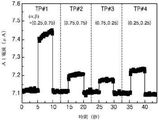
FIG. 11 is a graph showing the results of current measurement by the touch points (TP1 to TP4) of the
図9のように、テスト用タッチポイント(TP1〜TP4)が、TP1=(0.25、0.75)、TP2=(0.75、0.75)、TP3=(0.75、0.25)、TP4=(0.25、0.25)に設定され、TP1〜TP4が順次にタッチされうる。それぞれの角に配されたA1〜A4電流計310〜340によって電流が測定されうる。図11のように、TP1がタッチされれば、TP1と最も近いA1電流計310は、最も大きな電流値を示し、TP1から最も遠いA3電流計330は、最も低い電流値を示す。ストリップ状のイオン性タッチパネル10と類似に、2Dイオン性タッチパネル20の場合も、電極(200:210〜240)とタッチポイント(TP1〜TP4)との近接性に比例するように電流値が測定される。電流値を通じて2Dイオン性タッチパネル20でのタッチポイントの位置情報が計算されうる。
As shown in FIG. 9, the test touch points (TP1 to TP4) are TP1 = (0.25, 0.75), TP2 = (0.75, 0.75), TP3 = (0.75, 0. 25), TP4 = (0.25, 0.25) is set, and TP1 to TP4 can be touched in sequence. The current can be measured by A1-A4 ammeters 310-340 arranged at each corner. As shown in FIG. 11, when TP1 is touched, the
タッチパネルシステム及び四角形状のイオン性タッチパネル20の駆動例Driving example of touch panel system and square-shaped
図12は、本発明の一実施形態によるタッチパネルシステムを示すブロック図である。 FIG. 12 is a block diagram showing a touch panel system according to an embodiment of the present invention.
図12を参照すれば、制御ボード(Controller Board)70は、イオン性タッチパネル10−40とコンピュータ90との間を通信するように設計されうる。制御ボード70は、駆動信号部77で駆動電圧信号を生成し、この信号は、イオン性タッチパネル10−40の電極200に印加されうる。制御ボード70は、各電極200に流れる数mAの電流を測定し、AC−DCコンバータ71を通じてDCに変換することができる。位置を計算するために、増幅部73によって電流は増幅され、デジタル変換部75によってデジタル形態に変換されうる。制御ボード70では、電流に基づいてタッチポイントの位置を計算することができる。位置についての情報は、コンピュータ90に伝送され、コンピュータ90は、モニタ(M1、M2)にそれをディスプレイすることができる。コンピュータ90と例示したが、スマートフォン、PDA、タブレットなど一連の端末装置90が、これに該当しうる。また、イオン性タッチパネル10−40、制御ボード70及びコンピュータ90(または、端末装置90)が別途の構成であると示されているが、3つの要素は、1つの装置に統合された形態であり得る。例えば、スマートフォンの一側にイオン性タッチパネル10−40が適用されており、スマートフォンのCPUが制御ボード70の役割を行い、ディスプレイがモニタ(M1、M2)の代わりに位置情報を再び出力することも可能である。
With reference to FIG. 12, the
電流が互いに反比例する関係なので、タッチポイントの位置情報は、数式10及び数式11として表現される。
Since the currents are inversely proportional to each other, the position information of the touch points is expressed as
[数10]
α∝(I2+I3)/(I1+I2+I3+I4)
[Number 10]
α∝ (I 2 + I 3 ) / (I 1 + I 2 + I 3 + I 4 )
[数11]
β∝(I1+I2)/(I1+I2+I3+I4)
[Number 11]
β∝ (I 1 + I 2 ) / (I 1 + I 2 + I 3 + I 4 )
タッチによって、A1〜A4電流計310〜340から測定された、増えた電流が、I1−I4である。図11のように、同一のα座標をタッチすれば、数式10の値は同様に出る。例えば、タッチポイント(0.25、0.25)及び(0.25、0.75)の場合、数式10の値は、同様に0.517である。β座標の場合も、α座標の場合と同じである。
By touch, measured from A1~A4 ammeter 310-340, increasing the current is I 1 -I 4. As shown in FIG. 11, if the same α coordinate is touched, the value of the
図13及び図14は、本発明の第2実施形態によるイオン性タッチパネル20の駆動写真である。
13 and 14 are driving photographs of the
入力絵が表示された四角形状のイオン性タッチパネル20は、モニタ1(M1)に付着されうる。1mmの厚さのPMMA(ポリメチルメタクリレート)板がイオン性タッチパネル20とモニタ1(M1)との間に電気的絶縁体として差し込まれる。イオン性タッチパネル20は、制御ボード70を通じてコンピュータ90に連結され、モニタ1上で指500で入力絵に沿ってタッチを行えば、コンピュータ90は、制御ボード70から位置情報に基づいた出力絵をモニタ2(M2)に表示することができる。出力絵の角で若干の歪曲が観察される。図14のように、中心が同じである2個の四角形を描けば、外側四角形で歪曲がさらによく表われる。
The rectangular
図15は、本発明の第2実施形態によるイオン性タッチパネルの境界条件(Boundary Condition)を示す図面である。図16は、本発明の第2実施形態によるイオン性タッチパネルの電流のシミュレーション結果を示す図面である。 FIG. 15 is a drawing showing a boundary condition (Boundary Condition) of an ionic touch panel according to the second embodiment of the present invention. FIG. 16 is a drawing showing the simulation result of the current of the ionic touch panel according to the second embodiment of the present invention.
図13及び図14での歪曲について説明するために、電気的有限要素シミュレーション(Electrical Finite Element Simulation)が行われた。境界条件は、図15に示され、多様なタッチポイント(α、β)で4個の角を通じて流れる電流を計算した。均一な電気伝導度(1S/m)がパネルにわたって印加され、4つの角の電位は、1Vに固定された。パネルは、行列内に10個のグリッドに分離された。それぞれのタッチポイントと見なされるグリッドの交差地点は、順次にグラウンド化(OV)され、座標(α、β)は、グリッドの距離から計算された。各タッチポイントからの電流(I1、I2、I3、I4)は、(I2+I3)/(I1+I2+I3+I4)及び(I1+I2)/(I1+I2+I3+I4)によって変換されて、図14の(a)及び図14の(b)に示された。図14のように、パネルの中心付近の等高線は、角付近の等高線よりも整っている。1つの等高線のタッチポイントは、β座標が同じであると見なされる。一方、制御ボード70では、歪曲が表われないように位置情報を補正する過程をさらに行うこともできる。
An electrical finite element simulation was performed to illustrate the distortion in FIGS. 13 and 14. The boundary conditions are shown in FIG. 15 and the currents flowing through the four corners at various touch points (α, β) were calculated. Uniform electrical conductivity (1 S / m) was applied across the panel and the potentials at the four corners were fixed at 1 V. The panels were separated into 10 grids in the matrix. The intersections of the grid considered to be each touch point were sequentially grounded (OV) and the coordinates (α, β) were calculated from the distance of the grid. The currents (I 1 , I 2 , I 3 , I 4 ) from each touch point are (I 2 + I 3 ) / (I 1 + I 2 + I 3 + I 4 ) and (I 1 + I 2 ) / (I 1 + I). Transformed by 2 + I 3 + I 4 ) and shown in FIG. 14 (a) and FIG. 14 (b). As shown in FIG. 14, the contour lines near the center of the panel are more aligned than the contour lines near the corners. The touch points of one contour line are considered to have the same β coordinate. On the other hand, in the
円形のイオン性タッチパネル30Circular
以下、イオン性タッチパネル30の伸縮特性を主に説明する。図17は、本発明の第3実施形態による円形のイオン性タッチパネル30(図17の(a))及び伸張したイオン性タッチパネル30’(図17の(b))を示す概略図である。図18は、本発明の第3実施形態によるイオン性タッチパネル30’の駆動写真である。図19は、本発明の一実施形態によるハイドロゲルタッチ部100の可視光線領域での透過度を示すグラフである。
Hereinafter, the expansion / contraction characteristics of the
図17の(a)を参照すれば、4cmの直径の円形のイオン性タッチパネル30と二軸伸張器(Stretcher)とが準備された。円形のイオン性タッチパネル30は、二軸伸張器に付着され、Pt電極200を通じて制御ボード70に連結された。図17の(b)に示したように、円形のイオン性タッチパネル30’の直径が12.5cmに延びれば、面積が1000%伸張されることと同じである。また、図18を参照すれば、伸張された状態でも、イオン性タッチパネル30は駆動可能であり、星を描いた駆動例を確認することができる。
Referring to (a) of FIG. 17, a circular
そして、伸張前後において、円形のイオン性タッチパネル30裏の光学情報(イメージ)は、きれいに透過されて伝達されうる。図19を参照すれば、LiCl塩を含有するPAAmゲルの透過度T=I/I0(Iは、透過光の強度、I0は、照射光の強度)をUV−VIS spectroscopy(Agilent,cary−60)及びアクリルキュベット(cuvette)を用いて測定した結果が示されている。可視光線全領域(380〜750nm)で98%程度の高い透過度が表われた。透過度は、イオン性タッチパネル30の厚さが厚くなるほど減少するが、3mmの厚さのハイドロゲルが光学情報の遮断なしにイオン性タッチパネル30に使われる。
Then, before and after stretching, the optical information (image) on the back of the circular
図20は、本発明の第3実施形態によるイオン性タッチパネル30、30’の伸張前後の電流測定結果を示すグラフである。
FIG. 20 is a graph showing current measurement results before and after stretching of the
伸張前後、イオン性タッチパネル30、30’の中心タッチポイントのA1電流値が、図20のように測定される。伸張後に基線電流は、6.76μAから8.66μAに増える。基線電流の増加は、伸張による面積膨張の結果であって、空気のようなグラウンド環境から絶縁がよくできていない結果と見られる。
Before and after stretching, the A1 current value of the central touch points of the
伸張されたイオン性タッチパネル30’がタッチされれば、タッチ電流が基線電流に加えられる。伸張状態でタッチ電流は、0.53Aであり、これは、伸張前状態の電流0.48Aと類似している。伸張をしても、タッチ電流にはほとんど影響がない。そして、伸張状態で距離と電流との反比例関係は保持される。 When the stretched ionic touch panel 30'is touched, the touch current is applied to the baseline current. The touch current in the stretched state is 0.53 A, which is similar to the pre-stretched current of 0.48 A. Stretching has little effect on the touch current. Then, the inverse proportional relationship between the distance and the current is maintained in the stretched state.
図21は、本発明の第3実施形態によるイオン性タッチパネル30’のタッチポイントによる電流測定結果を示すグラフである。 FIG. 21 is a graph showing the current measurement result by the touch point of the ionic touch panel 30'according to the third embodiment of the present invention.
伸張されたイオン性タッチパネル30’で4個のタッチポイント(TP1〜TP4)が、TP1=(0.25、0.75)、TP2=(0.75、0.75)、TP3=(0.75、0.25)、TP4=(0.25、0.25)に設定され、TP1〜TP4が順次にタッチされうる。TP1からA1電流計310の距離が短いので、TP1のタッチ電流増加値が、他のタッチポイントよりも大きく表われる。したがって、イオン性タッチパネル30、30’の伸縮有無とは関係なく、電極200及び電流計300の距離から反比例の関係を有することを確認した。
Four touch points (TP1 to TP4) on the stretched ionic touch panel 30'are TP1 = (0.25, 0.75), TP2 = (0.75, 0.75), TP3 = (0. 75, 0.25), TP4 = (0.25, 0.25) are set, and TP1 to TP4 can be touched in sequence. Since the distance from TP1 to the
イオン性タッチパネル10−40の繰り返し伸縮テストRepeated expansion and contraction test of ionic touch panel 10-40
図22は、本発明の一実施形態によるイオン性タッチパネルの繰り返し伸縮に対する機械電気的テスト(Mechanical−Electrical Test)を示す図面である。図23は、図22のテスト結果を示すグラフである。 FIG. 22 is a drawing showing a mechanical-electrical test for repeated expansion and contraction of an ionic touch panel according to an embodiment of the present invention. FIG. 23 is a graph showing the test results of FIG. 22.
100回の反復されるローディングから機械電気的安定性がテストされうる。ストリップ状に2cm×15cm×3mmのサイズを有し、2M LiCl塩を含有するPAAmハイドロゲルに対して、最大伸縮λ=3に短縮繰り返しストレッチングを実施した。ゲルの抵抗は、Pt電極と共にLCRメーター(E4980AL−100,Agilent)で測定された。ストリップ状のハイドロゲルの上、下に5mm離れるように2個のクランプ(7cm×2cm×3mm)が付着された。ハイドロゲル両端は、Pt電極を通じてLCRメーターに連結され、Pt電極が連結されたストリップ状のハイドロゲルの上、下部は、繰り返しテスト中で増えない。変形がない時、2個のクランプの間で実質的に伸縮が作用する長さは、12cmである。テストは、50N capacity load cellが装着された装置(Instron model 3343)で行われた。 Mechanical electrical stability can be tested from 100 repeated loadings. PAAm hydrogel having a size of 2 cm × 15 cm × 3 mm in strip form and containing 2M LiCl salt was repeatedly stretched by shortening to a maximum expansion / contraction λ = 3. Gel resistance was measured with an LCR meter (E4980AL-100, Agilent) along with a Pt electrode. Two clamps (7 cm x 2 cm x 3 mm) were attached to the top and bottom of the strip-shaped hydrogel so as to be separated by 5 mm. Both ends of the hydrogel are connected to the LCR meter through the Pt electrode, and the upper and lower parts of the strip-shaped hydrogel to which the Pt electrode is connected do not increase during repeated tests. In the absence of deformation, the length of substantial expansion and contraction between the two clamps is 12 cm. The test was performed on a device (Instron model 3343) equipped with a 50N capacity load cell.
図23の(a)は、1、5、10、100回の繰り返し回数による抵抗測定結果を示す。λ=3である時、25%の最大変化幅を有し、繰り返し回数によって抵抗が急増した。繰り返しテストのうち、抵抗の増加は、ゲル内の水分の蒸発から起因されたと判断される。図23の(b)で、短縮伸張テストは、2M LiCl塩を含有する4cm×5cm×3mmのサイズのPAAmハイドロゲル試片に対して行われた。ハイドロゲル試片のモジュラス(Modulus)は、ほぼ4kPaであり、最大短縮延伸率(Elongation)は、λ=11に表われた。 (A) of FIG. 23 shows the resistance measurement result by the number of repetitions of 1, 5, 10, and 100 times. When λ = 3, it had a maximum change width of 25%, and the resistance increased sharply depending on the number of repetitions. In repeated tests, the increase in resistance is determined to be due to evaporation of water in the gel. In FIG. 23 (b), the shortened stretch test was performed on a PAAm hydrogel specimen containing a 2M LiCl salt and having a size of 4 cm × 5 cm × 3 mm. The modulus of the hydrogel specimen was approximately 4 kPa, and the maximum elongation was expressed at λ = 11.
上皮タッチパネル(Epidermal Touch Panel)形態のイオン性タッチパネル40
以下、人体に統合、付着可能なイオン性タッチパネル40について説明する。本明細書では、第4実施形態のイオン性タッチパネル40を上皮タッチパネルであると称する。
Hereinafter, the
図24は、本発明の第4実施形態による上皮タッチパネル形態のイオン性タッチパネル40を示す概略図である。図25は、本発明の第4実施形態による上皮タッチパネルを人体に付着した写真である。
FIG. 24 is a schematic view showing an
上皮タッチパネル40は、ハイドロゲルタッチ部100を基板600上に設置して構成することができる。ハイドロゲルタッチ部100の角には、電極200が連結されうる。基板600は、ハイドロゲルタッチ部100を人体に付着することができる付着手段の役割と共に、ハイドロゲルタッチ部100の絶縁体の役割を果たせる。基板600は、1mmの厚さのVHB(登録商標)フィルム(3M)が使われるが、ハイドロゲルタッチ部100の絶縁及び人体付着が可能な範囲内で、公知の付着手段を制限なしに使用することができる。
The
図25のように、上皮タッチパネル40は、腕などの身体部位に付着されうる。上皮タッチパネル40は、完全透明であって、タッチパネル裏の視覚コンテンツが伝達されうる。そして、上皮タッチパネル40は、ソフトかつ伸縮可能であって、ユーザが着用した時にも、楽な動きを提供することができる。
As shown in FIG. 25, the
図26は、本発明の第4実施形態によるイオン性タッチパネル40に基板付着前後の電流測定結果を示すグラフである。図27は、本発明の第4実施形態によるイオン性タッチパネルの基板厚さによる電流変化を示すグラフである。
FIG. 26 is a graph showing the current measurement results before and after the substrate is attached to the
図26を参照すれば、基線電流は、ハイドロゲルタッチ部100に基板600を付着した後に増えると測定される。絶縁層として作用する基板600の厚さ及び漏れ電流との関係を把握するために、1mmの厚さのアクリル板(Acrylic Plate)が基板600として使われた。基板600の厚さは、6mmから1mmであって、経時的に次第に減るようにした。図27に示したように、基板600の厚さが減るほど、厚さ1mm当たり約0.02mAの漏れ電流が減った。1mmの厚さの基板600を含む上皮タッチパネル40の付着によって誘導された電流は、0.25mAである。
Referring to FIG. 26, the baseline current is measured to increase after the
上皮タッチパネル40の中心(α=0.5、β=0.5)がタッチされる時、タッチ電流は、皮膚に付着されていない状態(0.36μA)よりも、付着された状態(0.12μA)で小さく表われる。しかし、電流信号は、タッチ位置を感知するのには十分な値を有する。
When the center (α = 0.5, β = 0.5) of the
上皮タッチパネル40が皮膚に付着されれば、皮膚を通じて漏れ電流が増加するために、基線電流は増加する。この結果から、漏れ電流の増加は、基線電流の増加を誘発し、タッチ電流を減少させる。タッチ電流の減少は、パネルの敏感度に影響を及ぼすので、パネルの絶縁を常に考慮しなければならない必要がある。本発明の上皮タッチパネル40は、絶縁層基板600があるにも、小さな漏れ電流が皮膚を通じて流れるが、測定可能な程度のタッチ電流がタッチ中に感知されるので、皮膚上で上皮タッチパネル40の駆動に影響を及ぼさない。
When the
図28は、本発明の第4実施形態によるイオン性タッチパネル40のタッチポイント(TP1〜TP4)による電流測定結果を示すグラフである。図29は、本発明の第4実施形態によるイオン性タッチパネル40の多様な応用例を示す写真である。
FIG. 28 is a graph showing the current measurement results by the touch points (TP1 to TP4) of the
上皮タッチパネル40上のタッチポイント(TP1〜TP4)を順次にタッチし、A1電流計310から電流を測定した。タッチによって増加する電流は、付着前である0.6〜1.4μAから付着後に0.07〜0.34μAに減少すると確認された。しかし、身体付着有無は、電流とタッチ位置との関係に影響を及ぼさない。図29を参照すれば、本発明の上皮タッチパネル40は、タッピング(Tapping)、ホールディング(Holding)、ドラッギング(Dragging)、スワイピング(Swiping)などの多様なモーションを感知し、適切なモーションを通じて文書き、音楽演奏、チェスゲームなどを行うことができる。
The touch points (TP1 to TP4) on the
本発明は、前述したように望ましい実施形態を挙げて図示して説明したが、前記実施形態に限定されず、本発明の精神を外れない範囲内で当業者によって多様な変形と変更とが可能である。そのような変形例及び変更例は、本発明と添付の特許請求の範囲の範囲内に属するものと認めなければならない。 Although the present invention has been illustrated and described with reference to desirable embodiments as described above, the present invention is not limited to the above embodiments and can be variously modified and modified by those skilled in the art within the scope of the spirit of the present invention. Is. It must be acknowledged that such modifications and modifications fall within the scope of the present invention and the appended claims.
本発明は、イオン性タッチパネル関連の技術分野に適用可能である。 The present invention is applicable to technical fields related to ionic touch panels.
10−40:イオン性タッチパネル
70:制御ボード
90:コンピュータ
100:ハイドロゲルタッチ部、塩を含有したハイドロゲル
200:電極
300:電流計
400:電源
500:指、タッチによるグラウンディング
M1、M2:モニタ
TP1〜TP4:タッチポイント
10-40: Ionic touch panel 70: Control board 90: Computer 100: Hydrogel touch part, Hydrogel containing salt 200: Electrode 300: Ammeter 400: Power supply 500: Finger, grounding by touch M1, M2: Monitor TP1-TP4: Touch point
Claims (9)
前記ハイドロゲルタッチ部の少なくとも2つの部分に連結される電極と、
を含むイオン性タッチパネルであって、
前記ハイドロゲルタッチ部がタッチされれば、前記電極からタッチされた部分までタッチ電流が誘導され、
前記イオン性タッチパネルは、タッチが行われた場合、前記イオン性タッチパネルに形成された静電容量の変化を感知して、タッチポイントの位置を計算することができ、
前記ハイドロゲルタッチ部は、ストリップ、四角形、円のうち何れか1つの形態を有し、
前記ハイドロゲルタッチ部は、ストリップ状であり、前記ハイドロゲルタッチ部の両端にそれぞれの前記電極が連結され、
前記ハイドロゲルタッチ部の長さが、L、前記ハイドロゲルタッチ部に流れる全体電流が、Itである場合、
前記ハイドロゲルタッチ部の一端からαL、他端から(1−α)Lの部分にタッチを行う時、
(1)式(1−α)=I 1 /I t 、及び(2)式α=I 2 /I t
(ここで、I 1 は、前記一端から測定された電流、I 2 は、前記他端から測定された電流、0≦α≦1)を通じてタッチ位置αを導出する、
イオン性タッチパネル。 Hydrogel touch part containing salt and
An electrode connected to at least two portions of the hydrogel touch portion and
Is an ionic touch panel that includes
When the hydrogel touch portion is touched, a touch current is induced from the electrode to the touched portion, and the touch current is induced.
When a touch is made, the ionic touch panel can sense a change in the capacitance formed on the ionic touch panel and calculate the position of the touch point .
The hydrogel touch portion has a form of any one of a strip, a quadrangle, and a circle.
The hydrogel touch portion has a strip shape, and the electrodes are connected to both ends of the hydrogel touch portion.
When the length of the hydrogel touch portion is L and the total current flowing through the hydrogel touch portion is It.
When touching αL from one end of the hydrogel touch portion and (1-α) L from the other end,
(1) (1-α) = I 1 / I t, and (2) below α = I 2 / I t
(Here, I 1 is the current measured from the other end, I 2 is the current measured from the other end, 0 ≦ α ≦ 1) to derive the touch position α.
Ionic touch panel.
前記ハイドロゲルタッチ部の少なくとも2つの部分に連結される電極と、
を含むイオン性タッチパネルであって、
前記ハイドロゲルタッチ部がタッチされれば、前記電極からタッチされた部分までタッチ電流が誘導され、
前記イオン性タッチパネルは、タッチが行われた場合、前記イオン性タッチパネルに形成された静電容量の変化を感知して、タッチポイントの位置を計算することができ、
前記ハイドロゲルタッチ部は、ストリップ、四角形、円のうち何れか1つの形態を有し、
前記ハイドロゲルタッチ部は、四角形状であり、前記ハイドロゲルタッチ部の4つの角にそれぞれの前記電極が連結され、
前記ハイドロゲルタッチ部がタッチされれば、角に配されたそれぞれの前記電極からタッチされた部分までそれぞれのタッチ電流が誘導され、前記それぞれのタッチ電流の数値から前記タッチされた部分の位置が計算され、
前記ハイドロゲルタッチ部上のタッチ座標が、(α、β)である場合(0≦α≦1、0≦β≦1)、
(1)式α∝(I2+I3)/(I1+I2+I3+I4)、及び(2)式β∝(I1+I2)/(I1+I2+I3+I4)
(ここで、I1、I2、I3、I4は、前記ハイドロゲルタッチ部の4つの角でそれぞれ測定された電流)を通じてタッチ位置α、βを導出する、
イオン性タッチパネル。 Hydrogel touch part containing salt and
An electrode connected to at least two portions of the hydrogel touch portion and
Is an ionic touch panel that includes
When the hydrogel touch portion is touched, a touch current is induced from the electrode to the touched portion, and the touch current is induced.
When a touch is made, the ionic touch panel can sense a change in the capacitance formed on the ionic touch panel and calculate the position of the touch point.
The hydrogel touch portion has a form of any one of a strip, a quadrangle, and a circle.
The hydrogel touch portion has a quadrangular shape, and the electrodes are connected to the four corners of the hydrogel touch portion.
When the hydrogel touch portion is touched, each touch current is induced from each of the electrodes arranged at the corner to the touched portion, and the position of the touched portion is determined from the numerical value of each touch current. Calculated,
When the touch coordinates on the hydrogel touch portion are (α, β) (0 ≦ α ≦ 1, 0 ≦ β ≦ 1),
Equation (1) α ∝ (I 2 + I 3 ) / (I 1 + I 2 + I 3 + I 4 ) and Equation (2) β ∝ (I 1 + I 2 ) / (I 1 + I 2 + I 3 + I 4 )
(Here, I 1 , I 2 , I 3 , and I 4 are the currents measured at the four corners of the hydrogel touch portion, respectively) to derive the touch positions α and β.
Ionic touch panel.
前記基板は、身体に統合可能であり、身体に対して絶縁性を有する請求項1に記載のイオン性タッチパネル。 The hydrogel touch portion is adhered to the substrate and
The ionic touch panel according to claim 1, wherein the substrate is integrated into the body and has an insulating property with respect to the body.
前記イオン性タッチパネルと電気的に連結され、タッチポイントの位置を計算する制御ボードと、
前記制御ボードからタッチポイントの情報を伝達されてディスプレイする端末装置と、
を含むイオン性タッチパネルシステムであって、
前記ハイドロゲルタッチ部がタッチされれば、前記電極からタッチされた部分までタッチ電流が誘導され、
前記イオン性タッチパネルは、タッチが行われた場合、前記イオン性タッチパネルに形成された静電容量の変化を感知して、タッチポイントの位置を計算することができ、
前記ハイドロゲルタッチ部は、ストリップ、四角形、円のうち何れか1つの形態を有し、
前記ハイドロゲルタッチ部は、ストリップ状であり、前記ハイドロゲルタッチ部の両端にそれぞれの前記電極が連結され、
前記ハイドロゲルタッチ部の長さが、L、前記ハイドロゲルタッチ部に流れる全体電流が、Itである場合、
前記ハイドロゲルタッチ部の一端からαL、他端から(1−α)Lの部分にタッチを行う時、
(1)式(1−α)=I 1 /I t 、及び(2)式α=I 2 /I t
(ここで、I 1 は、前記一端から測定された電流、I 2 は、前記他端から測定された電流、0≦α≦1)を通じてタッチ位置αを導出する、
イオン性タッチパネルシステム。 An ionic touch panel including a hydrogel touch portion containing a salt and electrodes connected to at least two portions of the hydrogel touch portion.
A control board that is electrically connected to the ionic touch panel and calculates the position of the touch point,
A terminal device that transmits and displays touch point information from the control board,
Is an ionic touch panel system that includes
When the hydrogel touch portion is touched, a touch current is induced from the electrode to the touched portion, and the touch current is induced.
When a touch is made, the ionic touch panel can sense a change in the capacitance formed on the ionic touch panel and calculate the position of the touch point .
The hydrogel touch portion has a form of any one of a strip, a quadrangle, and a circle.
The hydrogel touch portion has a strip shape, and the electrodes are connected to both ends of the hydrogel touch portion.
When the length of the hydrogel touch portion is L and the total current flowing through the hydrogel touch portion is It.
When touching αL from one end of the hydrogel touch portion and (1-α) L from the other end,
(1) (1-α) = I 1 / I t, and (2) below α = I 2 / I t
(Here, I 1 is the current measured from the other end, I 2 is the current measured from the other end, 0 ≦ α ≦ 1) to derive the touch position α.
Ionic touch panel system.
Applications Claiming Priority (3)
| Application Number | Priority Date | Filing Date | Title |
|---|---|---|---|
| KR10-2016-0097219 | 2016-07-29 | ||
| KR1020160097219A KR101768648B1 (en) | 2016-07-29 | 2016-07-29 | Ionic touch panel |
| PCT/KR2017/006182 WO2018021684A1 (en) | 2016-07-29 | 2017-06-14 | Ionic touch panel |
Publications (2)
| Publication Number | Publication Date |
|---|---|
| JP2019525332A JP2019525332A (en) | 2019-09-05 |
| JP6966533B2 true JP6966533B2 (en) | 2021-11-17 |
Family
ID=59753165
Family Applications (1)
| Application Number | Title | Priority Date | Filing Date |
|---|---|---|---|
| JP2019503251A Active JP6966533B2 (en) | 2016-07-29 | 2017-06-14 | Ionic touch panel |
Country Status (5)
| Country | Link |
|---|---|
| US (1) | US10860148B2 (en) |
| EP (1) | EP3493036B1 (en) |
| JP (1) | JP6966533B2 (en) |
| KR (1) | KR101768648B1 (en) |
| WO (1) | WO2018021684A1 (en) |
Families Citing this family (2)
| Publication number | Priority date | Publication date | Assignee | Title |
|---|---|---|---|---|
| CN107291296A (en) * | 2017-07-03 | 2017-10-24 | 京东方科技集团股份有限公司 | Touch-control sensing structure, method of work, touch base plate, preparation method, touch control display apparatus |
| KR20230030512A (en) * | 2021-08-25 | 2023-03-06 | 서울대학교산학협력단 | Triboresistive touch sensor |
Family Cites Families (11)
| Publication number | Priority date | Publication date | Assignee | Title |
|---|---|---|---|---|
| US4853493A (en) | 1988-05-06 | 1989-08-01 | Scriptel Holding, Inc. | Electrographic apparatus |
| DE69932662T2 (en) | 1998-03-12 | 2007-08-09 | Tyco Electronics Corp. | Touch-sensitive resistance screen |
| CN103076906B (en) * | 2011-10-26 | 2017-02-15 | 宸鸿科技(厦门)有限公司 | Touch panel and production method thereof |
| EP2901119A4 (en) * | 2012-09-25 | 2016-06-08 | Univ Arizona | Electrochemical pressure transducer |
| US10448895B2 (en) * | 2013-03-11 | 2019-10-22 | University Of Utah Research Foundation | Sensor systems |
| US10302586B2 (en) * | 2013-04-10 | 2019-05-28 | President And Fellows Of Harvard College | Stretchable ionics for transparent sensors and actuators |
| KR20170103758A (en) | 2014-12-03 | 2017-09-13 | 더 유니버시티 오브 브리티쉬 콜롬비아 | Flexible transparent sensor with ionically-conductive material |
| US10663358B2 (en) * | 2015-03-06 | 2020-05-26 | The University Of British Columbia | Method and sensor for pressure sensing based on electrical signal generated by redistribution of mobile ions in piezoionic layer |
| US10975205B2 (en) * | 2015-09-01 | 2021-04-13 | President And Fellows Of Harvard College | Hydrogels with improved mechanical properties below water freezing temperature |
| WO2017210795A1 (en) * | 2016-06-08 | 2017-12-14 | The University Of British Columbia | Surface sensor arrays using ionically conducting material |
| CN107316945B (en) * | 2017-06-23 | 2019-06-07 | 京东方科技集团股份有限公司 | A kind of OLED display panel and OLED display |
-
2016
- 2016-07-29 KR KR1020160097219A patent/KR101768648B1/en active IP Right Grant
-
2017
- 2017-06-14 EP EP17834628.4A patent/EP3493036B1/en active Active
- 2017-06-14 JP JP2019503251A patent/JP6966533B2/en active Active
- 2017-06-14 WO PCT/KR2017/006182 patent/WO2018021684A1/en unknown
- 2017-06-14 US US16/321,090 patent/US10860148B2/en active Active
Also Published As
| Publication number | Publication date |
|---|---|
| JP2019525332A (en) | 2019-09-05 |
| WO2018021684A1 (en) | 2018-02-01 |
| US20190163300A1 (en) | 2019-05-30 |
| EP3493036B1 (en) | 2023-06-14 |
| EP3493036A4 (en) | 2019-08-14 |
| EP3493036A1 (en) | 2019-06-05 |
| KR101768648B1 (en) | 2017-08-17 |
| US10860148B2 (en) | 2020-12-08 |
Similar Documents
| Publication | Publication Date | Title |
|---|---|---|
| CN105117058B (en) | A kind of touch panel, touch-control display panel and electronic equipment | |
| JP6100588B2 (en) | Film for touch panel and stylus pen used with the film | |
| TWI506502B (en) | Method of determining touch point and touch pressure | |
| KR101152554B1 (en) | Touch Screen Panel and Display Device Having the Same | |
| CN106873814A (en) | A kind of control method and electronic equipment | |
| TW201013484A (en) | Device and method for detecting position of object and image display system using the same device | |
| CN102473044A (en) | Capacitance type touch panel | |
| JP6966533B2 (en) | Ionic touch panel | |
| TW201239496A (en) | Touch-control e-paper display | |
| TW201133315A (en) | Touch panel and differential detection method for same | |
| CN206097087U (en) | Touch display device | |
| JP2019159302A (en) | Flexible display device and method for dividing flexible display | |
| Guo et al. | Skin-inspired self-healing semiconductive touch panel based on novel transparent stretchable hydrogels | |
| CN106201053A (en) | The sensitivity correction method of the touch input device of detection touch pressure and computer readable recording medium storing program for performing | |
| KR101472080B1 (en) | Touch sensing apparatus and method | |
| TWI459267B (en) | Method for detecting touch spot of touch panel | |
| TW201239718A (en) | Display devices, operation methods thereof, and electronic devices using the same | |
| TWI570608B (en) | Pressure sensing and touch sensitive panel, pressure sensing method, pressure sensing electronic device and control unit thereof | |
| TW201441902A (en) | Touch panel and dual touching mode input device using the same | |
| CN108227982A (en) | Touch sensor and the display device including touch sensor | |
| CN104635984B (en) | A kind of single face position sensor and its localization method | |
| JP6104764B2 (en) | Film for touch panel | |
| CN105759139A (en) | Touch screen test device and test method | |
| CN105807970B (en) | Hovering control device | |
| CN105807973B (en) | Electrostatic transducer |
Legal Events
| Date | Code | Title | Description |
|---|---|---|---|
| A621 | Written request for application examination |
Free format text: JAPANESE INTERMEDIATE CODE: A621 Effective date: 20190121 |
|
| A977 | Report on retrieval |
Free format text: JAPANESE INTERMEDIATE CODE: A971007 Effective date: 20200131 |
|
| A131 | Notification of reasons for refusal |
Free format text: JAPANESE INTERMEDIATE CODE: A131 Effective date: 20200303 |
|
| A521 | Request for written amendment filed |
Free format text: JAPANESE INTERMEDIATE CODE: A523 Effective date: 20200603 |
|
| A131 | Notification of reasons for refusal |
Free format text: JAPANESE INTERMEDIATE CODE: A131 Effective date: 20201006 |
|
| A521 | Request for written amendment filed |
Free format text: JAPANESE INTERMEDIATE CODE: A523 Effective date: 20201223 |
|
| A521 | Request for written amendment filed |
Free format text: JAPANESE INTERMEDIATE CODE: A523 Effective date: 20210128 |
|
| A02 | Decision of refusal |
Free format text: JAPANESE INTERMEDIATE CODE: A02 Effective date: 20210323 |
|
| A521 | Request for written amendment filed |
Free format text: JAPANESE INTERMEDIATE CODE: A523 Effective date: 20210721 |
|
| C60 | Trial request (containing other claim documents, opposition documents) |
Free format text: JAPANESE INTERMEDIATE CODE: C60 Effective date: 20210721 |
|
| A521 | Request for written amendment filed |
Free format text: JAPANESE INTERMEDIATE CODE: A523 Effective date: 20210728 |
|
| A911 | Transfer to examiner for re-examination before appeal (zenchi) |
Free format text: JAPANESE INTERMEDIATE CODE: A911 Effective date: 20210903 |
|
| C21 | Notice of transfer of a case for reconsideration by examiners before appeal proceedings |
Free format text: JAPANESE INTERMEDIATE CODE: C21 Effective date: 20210907 |
|
| TRDD | Decision of grant or rejection written | ||
| A01 | Written decision to grant a patent or to grant a registration (utility model) |
Free format text: JAPANESE INTERMEDIATE CODE: A01 Effective date: 20210921 |
|
| A61 | First payment of annual fees (during grant procedure) |
Free format text: JAPANESE INTERMEDIATE CODE: A61 Effective date: 20211021 |
|
| R150 | Certificate of patent or registration of utility model |
Ref document number: 6966533 Country of ref document: JP Free format text: JAPANESE INTERMEDIATE CODE: R150 |