JP6966336B2 - An information processing method, a device, and a program for causing a computer to execute the information processing method. - Google Patents
An information processing method, a device, and a program for causing a computer to execute the information processing method. Download PDFInfo
- Publication number
- JP6966336B2 JP6966336B2 JP2018003840A JP2018003840A JP6966336B2 JP 6966336 B2 JP6966336 B2 JP 6966336B2 JP 2018003840 A JP2018003840 A JP 2018003840A JP 2018003840 A JP2018003840 A JP 2018003840A JP 6966336 B2 JP6966336 B2 JP 6966336B2
- Authority
- JP
- Japan
- Prior art keywords
- virtual
- user
- virtual space
- hmd device
- hmd
- Prior art date
- Legal status (The legal status is an assumption and is not a legal conclusion. Google has not performed a legal analysis and makes no representation as to the accuracy of the status listed.)
- Active
Links
Images


Description
本開示は、仮想空間に仮想オブジェクトを表示する技術に関する。 The present disclosure relates to a technique for displaying a virtual object in a virtual space.
特許文献1には、仮想空間におけるウィジェットが視野の外に位置した時点で初期状態の位置に戻ることの記載がある。 Patent Document 1 describes that the widget returns to the initial state when it is located outside the field of view in the virtual space.
上記特許文献1に記載の技術に対して、ユーザが仮想空間内のウィジェットを見失わないために改善の余地がある。 There is room for improvement in the technique described in Patent Document 1 so that the user does not lose sight of the widget in the virtual space.
そこで、本開示においては、仮想空間内におけるウィジェットなどの移動対象の移動を改善する情報処理方法、装置、および当該情報処理方法をコンピュータに実行させるためのプログラムを提供することを目的とする。 Therefore, it is an object of the present disclosure to provide an information processing method, a device, and a program for causing a computer to execute the information processing method for improving the movement of a moving object such as a widget in a virtual space.
上述の課題を解決するために、本発明の情報処理方法は、表示部を備えるヘッドマウントデバイスを介してユーザに仮想空間を提供するためにコンピュータにより実行される情報処理方法であって、前記ユーザに関連付けられたキャラクタオブジェクト、移動対象を含む仮想空間データを特定するステップと、前記キャラクタオブジェクトに関連付けられた仮想視点を前記仮想空間内に特定し、前記仮想視点に基づいた視界画像を定義するステップと、前記視界画像を前記表示部に表示させるステップと、前記ヘッドマウントデバイスの動きに基づいて前記仮想視点を動かし始めるとともに、前記仮想視点の移動先である第1位置を予測するステップと、前記第1位置に基づいて前記移動対象の移動先である第2位置を特定するステップと、前記第2位置に、前記移動対象を移動させるステップと、を備える。 In order to solve the above-mentioned problems, the information processing method of the present invention is an information processing method executed by a computer to provide a virtual space to a user via a head mount device including a display unit, and the information processing method is executed by the user. A step of specifying virtual space data including a character object and a moving target associated with the character object, and a step of specifying a virtual viewpoint associated with the character object in the virtual space and defining a view image based on the virtual viewpoint. A step of displaying the view image on the display unit, a step of starting to move the virtual viewpoint based on the movement of the head mount device, and a step of predicting a first position to which the virtual viewpoint is moved. It includes a step of specifying a second position which is a destination of the movement target based on the first position, and a step of moving the movement target to the second position.
本会時によれば、移動対象を視界画像内に容易に捉えることができ、ユーザは移動対象または当該移動対象に基づいた処理を視界画像内で認識することができる。よって、ヘッドマウントデバイスを用いた仮想体験を改善することができる。 According to the present meeting, the moving object can be easily captured in the visual field image, and the user can recognize the moving object or the process based on the moving object in the visual field image. Therefore, it is possible to improve the virtual experience using the head mount device.
以下、図面を参照しつつ、本開示の実施の形態について説明する。以下の説明では、同一の部品には同一の符号を付してある。それらの名称および機能も同じである。したがって、それらについての詳細な説明は繰り返さない。 Hereinafter, embodiments of the present disclosure will be described with reference to the drawings. In the following description, the same parts are designated by the same reference numerals. Their names and functions are the same. Therefore, the detailed description of them will not be repeated.
[HMDシステムの構成]
図1を参照して、HMD(Head Mount Device)システム100の構成について説明する。図1は、ある実施の形態に従うHMDシステム100の構成の概略を表す図である。ある局面において、HMDシステム100は、家庭用のシステムとしてあるいは業務用のシステムとして提供される。
[HMD system configuration]
The configuration of the HMD (Head Mount Device)
HMDシステム100は、HMD装置110と、HMDセンサ120と、コントローラ160と、コンピュータ200とを備える。HMD装置110は、ディスプレイ112と、カメラ116と、マイク118と、注視センサ140とを含む。コントローラ160は、モーションセンサ130を含み得る。
The
ある局面において、コンピュータ200は、インターネットその他のネットワーク19に接続可能であり、ネットワーク19に接続されているサーバ150その他のコンピュータと通信可能である。別の局面において、HMD装置110は、HMDセンサ120の代わりに、センサ114を含み得る。
In one aspect, the
HMD装置110は、ユーザの頭部に装着され、動作中に仮想空間をユーザに提供し得る。より具体的には、HMD装置110は、右目用の画像および左目用の画像をディスプレイ112にそれぞれ表示する。ユーザの各目がそれぞれの画像を視認する場合、ユーザは、両目の視差に基づき当該画像を3次元の画像として認識し得る。ディスプレイ112はHMD装置110と一体に構成されていてもよいし、別体であってもよい。
The
ディスプレイ112は、例えば、非透過型の表示装置として実現される。ある局面において、ディスプレイ112は、ユーザの両目の前方に位置するようにHMD装置110の本体に配置されている。したがって、ユーザは、ディスプレイ112に表示される3次元画像を視認する場合、仮想空間に没入することができる。ある実施の形態において、仮想空間は、例えば、背景、ユーザが操作可能なオブジェクト、およびユーザが選択可能なメニューの画像等を含む。ある実施の形態において、ディスプレイ112は、所謂スマートフォンその他の情報表示端末が備える液晶ディスプレイまたは有機EL(Electro Luminescence)ディスプレイとして実現され得る。
The
ある局面において、ディスプレイ112は、右目用の画像を表示するためのサブディスプレイと、左目用の画像を表示するためのサブディスプレイとを含み得る。別の局面において、ディスプレイ112は、右目用の画像と左目用の画像とを一体として表示する構成であってもよい。この場合、ディスプレイ112は、高速シャッタを含む。高速シャッタは、画像がいずれか一方の目にのみ認識されるように、右目用の画像と左目用の画像とを交互に表示可能に作動する。
In certain aspects, the
カメラ116は、HMD装置110を装着するユーザの顔画像を取得する。カメラ116によって取得された顔画像は、画像解析処理によってユーザの表情を検知するために使用され得る。カメラ116は、例えば、瞳の動き、まぶたの開閉、および眉毛の動き等を検知するために、HMD装置110本体に内蔵された赤外線カメラであってもよい。あるいは、カメラ116は、ユーザの口、頬、および顎等の動きを検知するために、図1に示されるようにHMD装置110の外側に配置された外付けカメラであってもよい。また、カメラ116は、上述した赤外線カメラおよび外付けカメラの両方によって構成されてもよい。
The
マイク118は、ユーザが発した音声を取得する。マイク118によって取得された音声は、音声解析処理によってユーザの感情を検知するために使用され得る。当該音声は、仮想空間2に対して、音声による指示を与えるためにも使用され得る。また、当該音声は、ネットワーク19およびサーバ150等を介して、他のユーザが使用するHMDシステムに送られ、当該HMDシステムに接続されたスピーカ等から出力されてもよい。これにより、仮想空間を共有するユーザ間での会話(チャット)が実現される。
The
HMDセンサ120は、複数の光源(図示しない)を含む。各光源は例えば、赤外線を発するLED(Light Emitting Diode)により実現される。HMDセンサ120は、HMD装置110の動きを検出するためのポジショントラッキング機能を有する。HMDセンサ120は、この機能を用いて、現実空間内におけるHMD装置110の位置および傾きを検出する。
The
なお、別の局面において、HMDセンサ120は、カメラにより実現されてもよい。この場合、HMDセンサ120は、カメラから出力されるHMD装置110の画像情報を用いて、画像解析処理を実行することにより、HMD装置110の位置および傾きを検出することができる。
In another aspect, the
別の局面において、HMD装置110は、位置検出器として、HMDセンサ120の代わりに、またはさらに加えてセンサ114を備えてもよい。HMD装置110は、センサ114を用いて、HMD装置110自身の位置および傾きを検出し得る。例えば、センサ114が角速度センサ、地磁気センサ、加速度センサ、あるいはジャイロセンサ等である場合、HMD装置110は、HMDセンサ120の代わりに、これらの各センサのいずれかを用いて、自身の位置および傾きを検出し得る。一例として、センサ114が角速度センサである場合、角速度センサは、現実空間におけるHMD装置110の3軸周りの角速度を経時的に検出する。HMD装置110は、各角速度に基づいて、HMD装置110の3軸周りの角度の時間的変化を算出し、さらに、角度の時間的変化に基づいて、HMD装置110の傾きを算出する。また、HMD装置110は、透過型表示装置を備えていてもよい。この場合、当該透過型表示装置は、その透過率を調整することにより、一時的に非透過型の表示装置として構成可能であってもよい。また、視界画像は仮想空間を構成する画像の一部に、現実空間を提示する構成を含んでいてもよい。例えば、HMD装置110に搭載されたカメラで撮影した画像を視界画像の一部に重畳して表示させてもよいし、当該透過型表示装置の一部の透過率を高く設定することにより、視界画像の一部から現実空間を視認可能にしてもよい。
In another aspect, the
注視センサ140は、ユーザ190の右目および左目の視線が向けられる方向(視線方向)を検出する。当該方向の検出は、例えば、公知のアイトラッキング機能によって実現される。注視センサ140は、当該アイトラッキング機能を有するセンサにより実現される。ある局面において、注視センサ140は、右目用のセンサおよび左目用のセンサを含むことが好ましい。注視センサ140は、例えば、ユーザ190の右目および左目に赤外光を照射するとともに、照射光に対する角膜および虹彩からの反射光を受けることにより各眼球の回転角を検出するセンサであってもよい。注視センサ140は、検出した各回転角に基づいて、ユーザ190の視線方向を検知することができる。
The
サーバ150は、コンピュータ200にプログラムを送信して、ユーザに仮想空間2を提供し得る。
The
また、別の局面において、サーバ150は、他のユーザによって使用されるHMD装置に仮想現実を提供するための他のコンピュータ200と通信し得る。例えば、アミューズメント施設において、複数のユーザが参加型のゲームを行う場合、各コンピュータ200は、各ユーザの動作に基づく信号を他のコンピュータ200と通信して、同じ仮想空間において複数のユーザが共通のゲームを楽しむことを可能にする。
Also, in another aspect, the
コントローラ160は、ユーザ190からコンピュータ200への命令の入力を受け付ける。ある局面において、コントローラ160は、ユーザ190によって把持可能に構成される。別の局面において、コントローラ160は、ユーザ190の身体あるいは衣類の一部に装着可能に構成される。別の局面において、コントローラ160は、コンピュータ200から送られる信号に基づいて、振動、音、光のうちの少なくともいずれかを出力するように構成されてもよい。別の局面において、コントローラ160は、仮想現実を提供する空間に配置されるオブジェクトの位置および動き等を制御するためにユーザ190によって与えられる操作を受け付ける。
The
モーションセンサ130は、ある局面において、ユーザの手に取り付けられて、ユーザの手の動きを検出する。例えば、モーションセンサ130は、手の回転速度、回転数等を検出する。検出された信号は、コンピュータ200に送られる。モーションセンサ130は、例えば、手袋型のコントローラ160に設けられている。ある実施の形態において、現実空間における安全のため、コントローラ160は、手袋型のようにユーザ190の手に装着されることにより容易に飛んで行かないものに装着されるのが望ましい。別の局面において、ユーザ190に装着されないセンサがユーザ190の手の動きを検出してもよい。例えば、ユーザ190を撮影するカメラの信号が、ユーザ190の動作を表す信号として、コンピュータ200に入力されてもよい。モーションセンサ130とコンピュータ200とは、有線により、または無線により互いに接続される。無線の場合、通信形態は特に限られず、例えば、Bluetooth(登録商標)その他の公知の通信手法が用いられる。
The
[ハードウェア構成]
図2を参照して、本実施の形態に係るコンピュータ200について説明する。図2は、一局面に従うコンピュータ200のハードウェア構成の一例を表すブロック図である。コンピュータ200は、主たる構成要素として、プロセッサ10と、メモリ11と、ストレージ12と、入出力インターフェース13と、通信インターフェース14とを備える。各構成要素は、それぞれ、バス15に接続されている。
[Hardware configuration]
The
プロセッサ10は、コンピュータ200に与えられる信号に基づいて、あるいは、予め定められた条件が成立したことに基づいて、メモリ11またはストレージ12に格納されているプログラムに含まれる一連の命令を実行する。ある局面において、プロセッサ10は、CPU(Central Processing Unit)、MPU(Micro Processor Unit)、FPGA(Field-Programmable Gate Array)その他のデバイスとして実現される。
The
メモリ11は、プログラムおよびデータを一時的に保存する。プログラムは、例えば、ストレージ12からロードされる。メモリ11に保存されるデータは、コンピュータ200に入力されたデータと、プロセッサ10によって生成されたデータとを含む。ある局面において、メモリ11は、RAM(Random Access Memory)その他の揮発性メモリとして実現される。
The
ストレージ12は、プログラムおよびデータを永続的に保持する。ストレージ12は、例えば、ROM(Read-Only Memory)、ハードディスク装置、フラッシュメモリ、その他の不揮発性記憶装置として実現される。ストレージ12に格納されるプログラムは、HMDシステム100において仮想空間を提供するためのプログラム、シミュレーションプログラム、ゲームプログラム、ユーザ認証プログラム、および他のコンピュータ200との通信を実現するためのプログラム等を含む。ストレージ12に格納されるデータは、仮想空間を規定するためのデータおよびオブジェクト等を含む。
なお、別の局面において、ストレージ12は、メモリカードのように着脱可能な記憶装置として実現されてもよい。さらに別の局面において、コンピュータ200に内蔵されたストレージ12の代わりに、外部の記憶装置に保存されているプログラムおよびデータを使用する構成が使用されてもよい。このような構成によれば、例えば、アミューズメント施設のように複数のHMDシステム100が使用される場面において、プログラムおよびデータ等の更新を一括して行うことが可能になる。
In another aspect, the
ある実施の形態において、入出力インターフェース13は、HMD装置110、HMDセンサ120またはモーションセンサ130との間で信号を通信する。ある局面において、入出力インターフェース13は、USB(Universal Serial Bus)インターフェース、DVI(Digital Visual Interface)、HDMI(登録商標)(High-Definition Multimedia Interface)その他の端子を用いて実現される。なお、入出力インターフェース13は上述のものに限られない。
In certain embodiments, the input /
ある実施の形態において、入出力インターフェース13は、さらに、コントローラ160と通信し得る。例えば、入出力インターフェース13は、モーションセンサ130から出力された信号の入力を受ける。別の局面において、入出力インターフェース13は、プロセッサ10から出力された命令を、コントローラ160に送る。当該命令は、振動、音声出力、発光等をコントローラ160に指示する。コントローラ160は、当該命令を受信する場合、その命令に応じて、振動、音声出力または発光のいずれかを実行する。
In certain embodiments, the input /
通信インターフェース14は、ネットワーク19に接続されて、ネットワーク19に接続されている他のコンピュータ(例えば、サーバ150)と通信する。ある局面において、通信インターフェース14は、例えば、LAN(Local Area Network)その他の有線通信インターフェース、あるいは、WiFi(Wireless Fidelity)、Bluetooth(登録商標)、NFC(Near Field Communication)その他の無線通信インターフェースとして実現される。なお、通信インターフェース14は上述のものに限られない。
The
ある局面において、プロセッサ10は、ストレージ12にアクセスし、ストレージ12に格納されている1つ以上のプログラムをメモリ11にロードし、当該プログラムに含まれる一連の命令を実行する。当該1つ以上のプログラムは、コンピュータ200のオペレーティングシステム、仮想空間を提供するためのアプリケーションプログラム、コントローラ160を用いて仮想空間で実行可能なゲームソフトウェア等を含み得る。プロセッサ10は、入出力インターフェース13を介して、仮想空間を提供するための信号をHMD装置110に送る。HMD装置110は、その信号に基づいてディスプレイ112に映像を表示する。
In one aspect, the
サーバ150は、ネットワーク19を介して複数のHMDシステム100の各々の制御装置と接続される。
The
なお、図2に示される例では、コンピュータ200がHMD装置110の外部に設けられる構成が示されているが、別の局面において、コンピュータ200は、HMD装置110に内蔵されてもよい。一例として、ディスプレイ112を含む携帯型の情報通信端末(例えば、スマートフォン)がコンピュータ200として機能してもよい。
In the example shown in FIG. 2, the configuration in which the
また、コンピュータ200は、複数のHMD装置110に共通して用いられる構成であってもよい。このような構成によれば、例えば、複数のユーザに同一の仮想空間を提供することもできるので、各ユーザは同一の仮想空間で他のユーザと同一のアプリケーションを楽しむことができる。なお、このような場合、本実施形態における複数のHMDシステム100は、入出力インターフェース13により、コンピュータ200に直接接続されてもよい。また、本実施形態におけるサーバ150の各機能は、コンピュータ200に実装されてもよい。
Further, the
ある実施の形態において、HMDシステム100では、グローバル座標系が予め設定されている。グローバル座標系は、現実空間における鉛直方向、鉛直方向に直交する水平方向、ならびに、鉛直方向および水平方向の双方に直交する前後方向にそれぞれ平行な、3つの基準方向(軸)を有する。本実施の形態では、グローバル座標系は視点座標系の一つである。そこで、グローバル座標系における水平方向、鉛直方向(上下方向)、および前後方向は、それぞれ、x軸、y軸、z軸と規定される。より具体的には、グローバル座標系において、x軸は現実空間の水平方向に平行である。y軸は、現実空間の鉛直方向に平行である。z軸は現実空間の前後方向に平行である。
In one embodiment, the
ある局面において、HMDセンサ120は、赤外線センサを含む。赤外線センサが、HMD装置110の各光源から発せられた赤外線をそれぞれ検出する場合、HMD装置110の存在を検出する。HMDセンサ120は、さらに、各点の値(グローバル座標系における各座標値)に基づいて、HMD装置110を装着したユーザ190の動きに応じた、現実空間内におけるHMD装置110の位置および傾きを検出する。より詳しくは、HMDセンサ120は、経時的に検出された各値を用いて、HMD装置110の位置および傾きの時間的変化を検出できる。
In one aspect, the
グローバル座標系は現実空間の座標系と平行である。したがって、HMDセンサ120によって検出されたHMD装置110の各傾きは、グローバル座標系におけるHMD装置110の3軸周りの各傾きに相当する。HMDセンサ120は、グローバル座標系におけるHMD装置110の傾きに基づき、uvw視野座標系をHMD装置110に設定する。HMD装置110に設定されるuvw視野座標系は、HMD装置110を装着したユーザ190が仮想空間において物体を見る際の視点座標系に対応する。
The global coordinate system is parallel to the coordinate system in real space. Therefore, each inclination of the
[uvw視野座標系]
図3を参照して、uvw視野座標系について説明する。図3は、ある実施の形態に従うHMD装置110に設定されるuvw視野座標系を概念的に表す図である。HMDセンサ120は、HMD装置110の起動時に、グローバル座標系におけるHMD装置110の位置および傾きを検出する。プロセッサ10は、検出された値に基づいて、uvw視野座標系をHMD装置110に設定する。
[Uvw field coordinate system]
The uvw field coordinate system will be described with reference to FIG. FIG. 3 is a diagram conceptually representing the uvw field coordinate system set in the
図3に示されるように、HMD装置110は、HMD装置110を装着したユーザの頭部を中心(原点)とした3次元のuvw視野座標系を設定する。より具体的には、HMD装置110は、グローバル座標系を規定する水平方向、鉛直方向、および前後方向(x軸、y軸、z軸)を、グローバル座標系内においてHMD装置110の各軸周りの傾きだけ各軸周りにそれぞれ傾けることによって新たに得られる3つの方向を、HMD装置110におけるuvw視野座標系のピッチ方向(u軸)、ヨー方向(v軸)、およびロール方向(w軸)として設定する。
As shown in FIG. 3, the
ある局面において、HMD装置110を装着したユーザ190が直立し、かつ、正面を視認している場合、プロセッサ10は、グローバル座標系に平行なuvw視野座標系をHMD装置110に設定する。この場合、グローバル座標系における水平方向(x軸)、鉛直方向(y軸)、および前後方向(z軸)は、HMD装置110におけるuvw視野座標系のピッチ方向(u軸)、ヨー方向(v軸)、およびロール方向(w軸)に一致する。
In a certain aspect, when the
uvw視野座標系がHMD装置110に設定された後、HMDセンサ120は、HMD装置110の動きに基づいて、設定されたuvw視野座標系におけるHMD装置110の傾き(傾きの変化量)を検出できる。この場合、HMDセンサ120は、HMD装置110の傾きとして、uvw視野座標系におけるHMD装置110のピッチ角(θu)、ヨー角(θv)、およびロール角(θw)をそれぞれ検出する。ピッチ角(θu)は、uvw視野座標系におけるピッチ方向周りのHMD装置110の傾き角度を表す。ヨー角(θv)は、uvw視野座標系におけるヨー方向周りのHMD装置110の傾き角度を表す。ロール角(θw)は、uvw視野座標系におけるロール方向周りのHMD装置110の傾き角度を表す。
After the uvw field coordinate system is set in the
HMDセンサ120は、検出されたHMD装置110の傾き角度に基づいて、HMD装置110が動いた後のHMD装置110におけるuvw視野座標系を、HMD装置110に設定する。HMD装置110と、HMD装置110のuvw視野座標系との関係は、HMD装置110の位置および傾きに関わらず、常に一定である。HMD装置110の位置および傾きが変わる場合、当該位置および傾きの変化に連動して、グローバル座標系におけるHMD装置110のuvw視野座標系の位置および傾きが変化する。
The
ある局面において、HMDセンサ120は、赤外線センサからの出力に基づいて取得される赤外線の光強度および複数の点間の相対的な位置関係(例えば、各点間の距離など)に基づいて、HMD装置110の現実空間内における位置を、HMDセンサ120に対する相対位置として特定してもよい。また、プロセッサ10は、特定された相対位置に基づいて、現実空間内(グローバル座標系)におけるHMD装置110のuvw視野座標系の原点を決定してもよい。
In one aspect, the
[仮想空間]
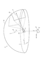
図4を参照して、仮想空間についてさらに説明する。図4は、ある実施の形態に従う仮想空間2を表現する一態様を概念的に表す図である。仮想空間2は、中心21の360度方向の全体を覆う全天球状の構造を有する。図4では、説明を複雑にしないために、仮想空間2のうちの上半分の天球が例示されている。仮想空間2では各メッシュが規定される。各メッシュの位置は、仮想空間2に規定されるXYZ座標系における座標値として予め規定されている。コンピュータ200は、仮想空間2に展開可能なコンテンツ(静止画、動画等)を構成する各部分画像を、仮想空間2において対応する各メッシュにそれぞれ対応付けて、ユーザによって視認可能な仮想空間画像22が展開される仮想空間2をユーザに提供する。
[Virtual space]
The virtual space will be further described with reference to FIG. FIG. 4 is a diagram conceptually representing one aspect of expressing the
ある局面において、仮想空間2では、中心21を原点とするXYZ座標系が規定される。XYZ座標系は、例えば、グローバル座標系に平行である。XYZ座標系は視点座標系の一種であるため、XYZ座標系における水平方向、鉛直方向(上下方向)、および前後方向は、それぞれX軸、Y軸、Z軸として規定される。したがって、XYZ座標系のX軸(水平方向)がグローバル座標系のx軸と平行であり、XYZ座標系のY軸(鉛直方向)がグローバル座標系のy軸と平行であり、XYZ座標系のZ軸(前後方向)がグローバル座標系のz軸と平行である。
In a certain aspect, the
HMD装置110の起動時、すなわちHMD装置110の初期状態において、仮想カメラ1が、仮想空間2の中心21に配置される。仮想カメラ1は、現実空間におけるHMD装置110の動きに連動して、仮想空間2を同様に移動する。これにより、現実空間におけるHMD装置110の位置および向きの変化が、仮想空間2において同様に再現される。
At the time of starting the
仮想カメラ1には、HMD装置110の場合と同様に、uvw視野座標系が規定される。仮想空間2における仮想カメラ1のuvw視野座標系は、現実空間(グローバル座標系)におけるHMD装置110のuvw視野座標系に連動するように規定されている。したがって、HMD装置110の傾きが変化する場合、それに応じて、仮想カメラ1の傾きも変化する。また、仮想カメラ1は、HMD装置110を装着したユーザの現実空間における移動に連動して、仮想空間2において移動することもできる。
As in the case of the
仮想カメラ1の向きは、仮想カメラ1の位置および傾きに応じて決まるので、ユーザが仮想空間画像22を視認する際に基準となる視線(基準視線5)は、仮想カメラ1の向きに応じて決まる。コンピュータ200のプロセッサ10は、基準視線5に基づいて、仮想空間2における視界領域23を規定する。視界領域23は、仮想空間2のうち、HMD装置110を装着したユーザの視界に対応する。
Since the orientation of the virtual camera 1 is determined according to the position and inclination of the virtual camera 1, the reference line of sight (reference line of sight 5) when the user visually recognizes the
注視センサ140によって検出されるユーザ190の視線方向は、ユーザ190が物体を視認する際の視点座標系における方向である。HMD装置110のuvw視野座標系は、ユーザ190がディスプレイ112を視認する際の視点座標系に等しい。また、仮想カメラ1のuvw視野座標系は、HMD装置110のuvw視野座標系に連動している。したがって、ある局面に従うHMDシステム100は、注視センサ140によって検出されたユーザ190の視線方向を、仮想カメラ1のuvw視野座標系におけるユーザの視線方向とみなすことができる。
The line-of-sight direction of the
[ユーザの視線]
図5を参照して、ユーザの視線方向の決定について説明する。図5は、ある実施の形態に従うHMD装置110を装着するユーザ190の頭部を上から表した図である。
[User's line of sight]
The determination of the line-of-sight direction of the user will be described with reference to FIG. FIG. 5 is a top view of the head of a
ある局面において、注視センサ140は、ユーザ190の右目および左目の各視線を検出する。ある局面において、ユーザ190が近くを見ている場合、注視センサ140は、視線R1およびL1を検出する。別の局面において、ユーザ190が遠くを見ている場合、注視センサ140は、視線R2およびL2を検出する。この場合、ロール方向wに対して視線R2およびL2がなす角度は、ロール方向wに対して視線R1およびL1がなす角度よりも小さい。注視センサ140は、検出結果をコンピュータ200に送信する。
In one aspect, the
コンピュータ200が、視線の検出結果として、視線R1およびL1の検出値を注視センサ140から受信した場合には、その検出値に基づいて、視線R1およびL1の交点である注視点N1を特定する。一方、コンピュータ200は、視線R2およびL2の検出値を注視センサ140から受信した場合には、視線R2およびL2の交点を注視点として特定する。コンピュータ200は、特定した注視点N1の位置に基づき、ユーザ190の視線方向N0を特定する。コンピュータ200は、例えば、ユーザ190の右目Rと左目Lとを結ぶ直線の中点と、注視点N1とを通る直線の延びる方向を、視線方向N0として検出する。視線方向N0は、ユーザ190が両目により実際に視線を向けている方向である。また、視線方向N0は、視界領域23に対してユーザ190が実際に視線を向けている方向に相当する。
When the
また、別の局面において、HMDシステム100は、テレビジョン放送受信チューナを備えてもよい。このような構成によれば、HMDシステム100は、仮想空間2においてテレビ番組を表示することができる。
Further, in another aspect, the
さらに別の局面において、HMDシステム100は、インターネットに接続するための通信回路、あるいは、電話回線に接続するための通話機能を備えていてもよい。
In yet another aspect, the
[視界領域]
図6および図7を参照して、視界領域23について説明する。図6は、仮想空間2において視界領域23をX方向から見たYZ断面を表す図である。図7は、仮想空間2において視界領域23をY方向から見たXZ断面を表す図である。
[Visibility area]
The
図6に示されるように、YZ断面における視界領域23は、領域24を含む。領域24は、仮想カメラ1の基準視線5と仮想空間2のYZ断面とによって定義される。プロセッサ10は、仮想空間2における基準視線5を中心として極角αを含む範囲を、領域24として規定する。
As shown in FIG. 6, the field of
図7に示されるように、XZ断面における視界領域23は、領域25を含む。領域25は、基準視線5と仮想空間2のXZ断面とによって定義される。プロセッサ10は、仮想空間2における基準視線5を中心とした方位角βを含む範囲を、領域25として規定する。
As shown in FIG. 7, the field of
ある局面において、HMDシステム100は、コンピュータ200からの信号に基づいて、視界画像をディスプレイ112に表示させることにより、ユーザ190に仮想空間を提供する。視界画像は、仮想空間画像22のうち視界領域23に重畳する部分に相当する。ユーザ190が、頭に装着したHMD装置110を動かす場合、その動きに連動して仮想カメラ1も動く。その結果、仮想空間2における視界領域23の位置が変化する。これにより、ディスプレイ112に表示される視界画像は、仮想空間画像22のうち、仮想空間2においてユーザが向いた方向の視界領域23に重畳する画像に更新される。ユーザは、仮想空間2における所望の方向を視認することができる。
In one aspect, the
ユーザ190は、HMD装置110を装着している間、現実世界を視認することなく、仮想空間2に展開される仮想空間画像22のみを視認できる。そのため、HMDシステム100は、仮想空間2への高い没入感覚をユーザに与えることができる。
While wearing the
ある局面において、プロセッサ10は、HMD装置110を装着したユーザ190の現実空間における移動に連動して、仮想空間2において仮想カメラ1を移動し得る。この場合、プロセッサ10は、仮想空間2における仮想カメラ1の位置および向きに基づいて、HMD装置110のディスプレイ112に投影される画像領域(すなわち、仮想空間2における視界領域23)を特定する。すなわち、仮想カメラ1によって、仮想空間2におけるユーザ190の視野が定義される。
In a certain aspect, the
ある実施の形態に従う場合、仮想カメラ1は、二つの仮想カメラ、すなわち、右目用の画像を提供するための仮想カメラと、左目用の画像を提供するための仮想カメラとを含むことが望ましい。また、ユーザ190が3次元の仮想空間2を認識できるように、適切な視差が、二つの仮想カメラに設定されていることが好ましい。本実施の形態においては、仮想カメラ1が二つの仮想カメラを含み、二つの仮想カメラのロール方向が合成されることによって生成されるロール方向(w)がHMD装置110のロール方向(w)に適合されるように構成されているものとして、本開示に係る技術思想を例示する。
According to certain embodiments, the virtual camera 1 preferably includes two virtual cameras, i.e., a virtual camera for providing an image for the right eye and a virtual camera for providing an image for the left eye. Further, it is preferable that an appropriate parallax is set in the two virtual cameras so that the
[コントローラ]
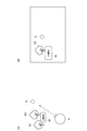
図8を参照して、コントローラ160の一例について説明する。図8は、ある実施の形態に従うコントローラ160の概略構成を表す図である。
[controller]
An example of the
図8の状態(A)に示されるように、ある局面において、コントローラ160は、右コントローラ160Rと左コントローラとを含み得る。右コントローラ160Rは、ユーザ190の右手で操作される。左コントローラは、ユーザ190の左手で操作される。ある局面において、右コントローラ160Rと左コントローラとは、別個の装置として対称に構成される。したがって、ユーザ190は、右コントローラ160Rを把持した右手と、左コントローラを把持した左手とをそれぞれ自由に動かすことができる。別の局面において、コントローラ160は両手の操作を受け付ける一体型のコントローラであってもよい。以下、右コントローラ160Rについて説明する。
As shown in the state (A) of FIG. 8, in a certain aspect, the
右コントローラ160Rは、グリップ30と、フレーム31と、天面32とを備える。グリップ30は、ユーザ190の右手によって把持されるように構成されている。例えば、グリップ30は、ユーザ190の右手の掌と3本の指(中指、薬指、小指)とによって保持され得る。
The
グリップ30は、ボタン33,34と、モーションセンサ130とを含む。ボタン33は、グリップ30の側面に配置され、右手の中指による操作を受け付ける。ボタン34は、グリップ30の前面に配置され、右手の人差し指による操作を受け付ける。ある局面において、ボタン33,34は、トリガー式のボタンとして構成される。モーションセンサ130は、グリップ30の筐体に内蔵されている。なお、ユーザ190の動作がカメラその他の装置によってユーザ190の周りから検出可能である場合には、グリップ30は、モーションセンサ130を備えなくてもよい。
The
フレーム31は、その円周方向に沿って配置された複数の赤外線LED35を含む。赤外線LED35は、コントローラ160を使用するプログラムの実行中に、当該プログラムの進行に合わせて赤外線を発光する。赤外線LED35から発せられた赤外線は、右コントローラ160Rと左コントローラとの各位置および姿勢(傾き、向き)等を検出するために使用され得る。図8に示される例では、二列に配置された赤外線LED35が示されているが、配列の数は図8に示されるものに限られない。一列あるいは3列以上の配列が使用されてもよい。
The
天面32は、ボタン36,37と、アナログスティック38とを備える。ボタン36,37は、プッシュ式ボタンとして構成される。ボタン36,37は、ユーザ190の右手の親指による操作を受け付ける。アナログスティック38は、ある局面において、初期位置(ニュートラルの位置)から360度任意の方向への操作を受け付ける。当該操作は、例えば、仮想空間2に配置されるオブジェクトを移動させるための操作を含む。
The
ある局面において、右コントローラ160Rおよび左コントローラは、赤外線LED35その他の部材を駆動するための電池を含む。電池は、充電式、ボタン型、乾電池型等を含むが、これらに限定されない。別の局面において、右コントローラ160Rおよび左コントローラは、例えば、コンピュータ200のUSBインターフェースに接続され得る。この場合、右コントローラ160Rおよび左コントローラは、電池を必要としない。
In one aspect, the
図8の状態(A)および状態(B)に示されるように、例えば、ユーザ190の右手810に対して、ヨー、ロール、ピッチの各方向が規定される。ユーザ190が親指と人差し指とを伸ばした場合に、親指の伸びる方向がヨー方向、人差し指の伸びる方向がロール方向、ヨー方向の軸およびロール方向の軸によって規定される平面に垂直な方向がピッチ方向として規定される。
As shown in the states (A) and (B) of FIG. 8, for example, the yaw, roll, and pitch directions are defined for the
[HMD装置の制御装置]
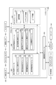
図9を参照して、HMD装置110の制御装置について説明する。ある実施の形態において、制御装置は周知の構成を有するコンピュータ200によって実現される。図9は、ある実施の形態に従うコンピュータ200をモジュール構成として表すブロック図である。
[Control device for HMD device]
The control device of the
図9に示されるように、コンピュータ200は、表示制御モジュール220と、仮想空間制御モジュール230と、メモリモジュール240と、通信制御モジュール250とを備える。表示制御モジュール220は、サブモジュールとして、仮想カメラ制御モジュール221と、視界領域決定モジュール222と、視界画像生成モジュール223と、基準視線特定モジュール224とを含む。仮想空間制御モジュール230は、サブモジュールとして、仮想空間定義モジュール231と、仮想オブジェクト制御モジュール232と、操作オブジェクト制御モジュール233と、予測制御モジュール234とを含む。
As shown in FIG. 9, the
ある実施の形態において、表示制御モジュール220と仮想空間制御モジュール230とは、プロセッサ10によって実現される。別の実施の形態において、複数のプロセッサ10が表示制御モジュール220と仮想空間制御モジュール230として作動してもよい。メモリモジュール240は、メモリ11またはストレージ12によって実現される。通信制御モジュール250は、通信インターフェース14によって実現される。
In certain embodiments, the
ある局面において、表示制御モジュール220は、HMD装置110のディスプレイ112における画像表示を制御する。仮想カメラ制御モジュール221は、仮想空間2に仮想カメラ1を配置し、仮想カメラ1の挙動、向き等を制御する。視界領域決定モジュール222は、HMD装置110を装着したユーザの頭の向きに応じて、視界領域23を規定する。視界画像生成モジュール223は、決定された視界領域23に基づいて、ディスプレイ112に表示される視界画像を生成する。また、視界画像生成モジュール223は、視界画像に含まれるキャラクタオブジェクトの表示態様を決定する。基準視線特定モジュール224は、注視センサ140からの信号に基づいて、ユーザ190の視線を特定する。
In one aspect, the
仮想空間制御モジュール230は、ユーザ190に提供される仮想空間2を制御する。仮想空間定義モジュール231は、仮想空間2を表す仮想空間データを生成することにより、HMDシステム100における仮想空間2を規定する。
The virtual
仮想オブジェクト制御モジュール232は、仮想空間2に配置される仮想オブジェクトを生成する。また、仮想オブジェクト制御モジュール232は、仮想空間2における仮想オブジェクトおよびキャラクタオブジェクトの動作(移動および状態変化等)を制御する。仮想オブジェクトは、例えば、ゲームのストーリーの進行に従って配置される森、山その他を含む風景、動物、UI(User Interface)画面などのウィジェット等の移動対象を含み得る。キャラクタオブジェクトは、仮想空間2においてHMD装置110を装着したユーザに関連付けられたオブジェクトであり、アバターと称する場合もある。本開示においては、アバターを含んだオブジェクトをキャラクタオブジェクトと称することにする。
The virtual
また、移動対象とは、ユーザ(HMD装置110)の動きに応じて仮想空間内を移動して、視界画像内に視認可能に設定された仮想オブジェクトである。例えば、ユーザにより操作可能なUI(User Interface)画面などのウィジェットは、ユーザが動いても視界画像に視認可能にしておくことが好ましい。移動対象のその他のものとして、UI画面などのウィジェットのほか、敵キャラクタオブジェクト、他のユーザに関連付けられたキャラクタオブジェクト、制御オブジェクトなどのステージオブジェクトを含む。ステージオブジェクトは、例えば、上記オブジェクトの外観を規定するためのオブジェクト(質感を規定するためのLight等)や、敵キャラクタオブジェクトの移動経路を定義するためのオブジェクトである。なお、ウィジェット、敵キャラクタオブジェクトおよび他のユーザのキャラクタオブジェクトは、典型的には視認可能に表示される情報である。一方で、ステージオブジェクトは、典型的には視認不可能な制御情報である。ステージオブジェクトなど不可視の制御情報を移動させることで、その情報に基づいた制御を視界画像においてユーザは認識し得る。 Further, the movement target is a virtual object that moves in the virtual space according to the movement of the user (HMD device 110) and is set to be visible in the field of view image. For example, it is preferable that a widget such as a UI (User Interface) screen that can be operated by the user is visible in the field of view image even if the user moves. Other objects to be moved include widgets such as UI screens, as well as stage objects such as enemy character objects, character objects associated with other users, and control objects. The stage object is, for example, an object for defining the appearance of the object (Light for defining the texture, etc.) and an object for defining the movement path of the enemy character object. Note that the widget, the enemy character object, and the character object of another user are typically information that is visually displayed. On the other hand, the stage object is typically invisible control information. By moving invisible control information such as a stage object, the user can recognize the control based on the information in the field image.
操作オブジェクト制御モジュール233は、仮想空間2に配置されるオブジェクトを操作するための操作オブジェクトを仮想空間2に配置する。ある局面において、操作オブジェクトは、例えば、HMD装置110を装着したユーザの手に相当する手オブジェクト(仮想手)、ユーザの指に相当する指オブジェクト、ユーザが使用するスティックに相当するスティックオブジェクト等を含み得る。操作オブジェクトが指オブジェクトの場合、特に、操作オブジェクトは、当該指が指し示す方向(軸方向)の軸の部分に対応している。
The operation object control module 233 arranges the operation object for operating the object arranged in the
仮想空間制御モジュール230は、仮想空間2に配置されるオブジェクトのそれぞれが、他のオブジェクトと衝突した場合に、当該衝突を検出する。仮想空間制御モジュール230は、例えば、あるオブジェクトと、別のオブジェクトとが触れたタイミングを検出することができ、当該検出がされたときに、予め定められた処理を行う。仮想空間制御モジュール230は、オブジェクトとオブジェクトとが触れている状態から離れたタイミングを検出することができ、当該検出がされたときに、予め定められた処理を行う。仮想空間制御モジュール230は、オブジェクトとオブジェクトとが触れている状態であることを検出することができる。具体的には、操作オブジェクト制御モジュール233は、操作オブジェクトと、他のオブジェクト(例えば、仮想オブジェクト制御モジュール232によって配置される仮想オブジェクト)とが触れた時に、これら操作オブジェクトと他のオブジェクトとが触れたことを検出して、予め定められた処理を行う。
When each of the objects arranged in the
メモリモジュール240は、コンピュータ200が仮想空間2をユーザ190に提供するために使用されるデータを保持している。ある局面において、メモリモジュール240は、空間情報241と、オブジェクト情報242と、ユーザ情報243とを保持している。空間情報241には、例えば、仮想空間2を提供するために規定された1つ以上のテンプレートが含まれている。オブジェクト情報242には、例えば、仮想空間2において再生されるコンテンツ、当該コンテンツで使用されるオブジェクトを配置するための情報、そのほかキャラクタオブジェクトの描画データやそのサイズ情報などの属性情報等が含まれている。当該コンテンツは、例えば、ゲーム、現実社会と同様の風景を表したコンテンツ等を含み得る。さらに、オブジェクト情報242には、仮想オブジェクト、他のユーザに関連付けられたキャラクタオブジェクト、およびメニュー画面などのウィジェットなどの移動対象の配置位置に関する相対的な優先度を示した情報を含む。ユーザ情報243には、例えば、HMDシステム100の制御装置としてコンピュータ200を機能させるためのプログラム、オブジェクト情報242に保持される各コンテンツを使用するアプリケーションプログラム等が含まれている。
The
メモリモジュール240に格納されているデータおよびプログラムは、HMD装置110のユーザによって入力される。あるいは、プロセッサ10が、当該コンテンツを提供する事業者が運営するコンピュータ(例えば、サーバ150)からプログラムあるいはデータをダウンロードして、ダウンロードされたプログラムあるいはデータをメモリモジュール240に格納する。
The data and programs stored in the
通信制御モジュール250は、ネットワーク19を介して、サーバ150その他の情報通信装置と通信し得る。
The
ある局面において、表示制御モジュール220および仮想空間制御モジュール230は
、例えば、ユニティテクノロジーズ社によって提供されるUnity(登録商標)を用い
て実現され得る。別の局面において、表示制御モジュール220および仮想空間制御モジ
ュール230は、各処理を実現する回路素子の組み合わせとしても実現され得る。
In certain aspects, the
コンピュータ200における処理は、ハードウェアと、プロセッサ10により実行されるソフトウェアとによって実現される。このようなソフトウェアは、ハードディスクその他のメモリモジュール240に予め格納されている場合がある。また、ソフトウェアは、CD−ROMその他のコンピュータ読み取り可能な不揮発性のデータ記録媒体に格納されて、プログラム製品として流通している場合もある。あるいは、当該ソフトウェアは、インターネットその他のネットワークに接続されている情報提供事業者によってダウンロード可能なプログラム製品として提供される場合もある。このようなソフトウェアは、光ディスク駆動装置その他のデータ読取装置によってデータ記録媒体から読み取られて、あるいは、通信制御モジュール250を介してサーバ150その他のコンピュータからダウンロードされた後、メモリモジュール240に一旦格納される。そのソフトウェアは、プロセッサ10によってメモリモジュール240から読み出され、実行可能なプログラムの形式でRAMに格納される。プロセッサ10は、そのプログラムを実行する。
The processing in the
図9に示されるコンピュータ200を構成するハードウェアは、一般的なものである。したがって、本実施の形態に係る最も本質的な部分は、コンピュータ200に格納されたプログラムであるともいえる。なお、コンピュータ200のハードウェアの動作は周知であるので、詳細な説明は繰り返さない。
The hardware constituting the
なお、データ記録媒体としては、CD−ROM、FD(Flexible Disk)、ハードディスクに限られず、磁気テープ、カセットテープ、光ディスク(MO(Magnetic Optical Disc)/MD(Mini Disc)/DVD(Digital Versatile Disc))、IC(Integrated Circuit)カード(メモリカードを含む)、光カード、マスクROM、EPROM(Erasable Programmable Read-Only Memory)、EEPROM(Electrically Erasable Programmable Read-Only Memory)、フラッシュROMなどの半導体メモリ等の固定的にプログラムを担持する不揮発性のデータ記録媒体でもよい。 The data recording medium is not limited to CD-ROM, FD (Flexible Disk), and hard disk, but also magnetic tape, cassette tape, optical disc (MO (Magnetic Optical Disc) / MD (Mini Disc) / DVD (Digital Versatile Disc)). ), IC (Integrated Circuit) card (including memory card), optical card, mask ROM, EPROM (Erasable Programmable Read-Only Memory), EEPROM (Electrically Erasable Programmable Read-Only Memory), semiconductor memory such as flash ROM, etc. It may be a non-volatile data recording medium that fixedly carries the program.
ここでいうプログラムとは、プロセッサ10により直接実行可能なプログラムだけでなく、ソースプログラム形式のプログラム、圧縮処理されたプログラム、暗号化されたプログラム等を含み得る。
The program referred to here may include not only a program that can be directly executed by the
[制御構造]
図10を参照して、本実施の形態に係るコンピュータ200の制御構造について説明す
る。図10は、ユーザ190によって使用されるHMDシステム100がユーザ190に
仮想空間2を提供するために実行する処理を表すフローチャートである。
[Control structure]
The control structure of the
ステップS1において、コンピュータ200のプロセッサ10は、仮想空間定義モジュール231として、ユーザに関連付けられたキャラクタオブジェクトを含む仮想空間画像データを特定し、仮想空間2を定義する。また、プロセッサ10は、仮想オブジェクト制御モジュール232、操作オブジェクト制御モジュール233として、この仮想空間2に仮想オブジェクト(ウィジェット等の移動対象を含む)および操作オブジェクトを配置する。仮想空間定義モジュール231は、その動作を仮想空間2内に制御可能に定義する。
In step S1, the
ステップS2において、プロセッサ10は、仮想カメラ制御モジュール221として、仮想カメラ1を初期化する。例えば、プロセッサ10は、メモリのワーク領域において、仮想カメラ1を仮想空間2において予め規定された中心点に配置し、仮想カメラ1の視線をユーザ190が向いている方向に向ける。
In step S2, the
ステップS3において、プロセッサ10は、視界画像生成モジュール223として、初期の視界画像を表示するための視界画像データを生成する。生成された視界画像データは、視界画像生成モジュール223を介して通信制御モジュール250によってHMD装置110に送られる。
In step S3, the
ステップS4において、HMD装置110のディスプレイ112は、コンピュータ200から受信した信号に基づいて、視界画像を表示する。HMD装置110を装着したユーザ190は、視界画像を視認する場合に仮想空間2を認識し得る。
In step S4, the
ステップS5において、HMDセンサ120は、HMD装置110から発信される複数の赤外線光に基づいて、HMD装置110の位置と傾きを検出する。さらにセンサ114は、HMD装置110の動きの加速度を検出する。検出結果は、動き検出データとして、コンピュータ200に送られる。
In step S5, the
ステップS6において、プロセッサ10は、視界領域決定モジュール222として、HMD装置110の位置と傾きとに基づいて、HMD装置110を装着したユーザ190の視界方向を特定する。ここでは、プロセッサ10は仮想視点を視界方向として特定する。仮想視点は、仮想カメラ1からの視線の方向の内、仮想カメラ1から予め設定された距離となる位置に仮想的に設定される。プロセッサ10は、アプリケーションプログラムを実行し、アプリケーションプログラムに含まれる命令に基づいて、仮想空間2にオブジェクトを配置する。
In step S6, the
ステップS7において、プロセッサ10は、視界画像生成モジュール223として、HMD装置110の動きに応じた視界画像を表示するための視界画像データを生成し、生成した視界画像データをHMD装置110に出力する。
In step S7, the
ステップS8において、HMD装置110のディスプレイ112は、受信した視界画像データに基づいて視界画像を更新し、更新後の視界画像を表示する。
In step S8, the
上述のステップS5〜S10の処理は繰り返し実行される。したがって、仮想視点は、HMD装置110の動きに伴って移動し、HMD装置110の動きが完了する場合、仮想視点の移動が完了する。さらに、本実施形態においては、HMD装置110の動き始めたときに、その動きが完了したときの仮想視点の移動先(第1位置)を予測する。そして、HMD装置110動きが完了するまでの間に、プロセッサ10は、仮想視点の移動先に基づいて移動対象の移動先(第2位置)を特定し、移動対象を移動させる。
The processes of steps S5 to S10 described above are repeatedly executed. Therefore, the virtual viewpoint moves with the movement of the
つぎに、図10におけるステップS5〜S8の間に行われる、本実施形態における仮想視点の予測処理(第1位置の予測)および移動対象の特定処理(第2位置の特定)について説明する。図11は、仮想視点の移動先となる第1位置を予測し、その予測に基づいて移動対象の移動先となる第2位置を特定する予測制御モジュールとして動作するプロセッサ10の処理を示すフローチャートである。
Next, the virtual viewpoint prediction process (prediction of the first position) and the movement target identification process (identification of the second position) in the present embodiment, which are performed between steps S5 to S8 in FIG. 10, will be described. FIG. 11 is a flowchart showing the processing of the
ステップS101において、センサ114はHMD装置110の動きに従ってその加速度などを検出し、プロセッサ10は、HMD装置110が動いたことを検出する。ステップS101は、図10におけるステップS5に相当する。
In step S101, the
ステップS102において、プロセッサ10は、センサ114により検出されたHMD装置110の加速度が閾値以上であるか否かを判断する。なお、ここではセンサ114は、HMD装置110のヨー角の角加速度を検出する。
In step S102, the
ステップS103において、プロセッサ10は、センサ114により検出されたHMD装置110の加速度に基づいて仮想視点の移動先を予測する。
In step S103, the
ステップS104において、プロセッサ10は、仮想視点に基づいて移動対象の移動先を特定する。
In step S104, the
ステップS105において、プロセッサ10は、移動対象の移動前の位置が、予測した仮想視点の移動先に基づいた視界画像内に含まれているか否かを判断する。ステップS105において、移動対象の移動前の位置が視界画像内に含まれていると判断する場合(ステップS105:YES)、ステップS106において、プロセッサ10は、当該移動対象は、視界画像において固定の配置位置に配置されるものであるか否かを判断する。なお、固定の配置位置とは、仮想視点との間で設定された位置関係にあることを示す。したがって、例えば、視界画像において左上にUI画面が表示されることが設定されている場合には、常にその位置に表示されるよう、仮想視点の位置に基づいた仮想空間内の位置にUI画面のオブジェクトが配置される。このような配置位置に関する情報(固定配置の対象となるオブジェクト等および仮想視点との位置関係を示す情報)は、事前にオブジェクト情報242に記憶されている。
In step S105, the
プロセッサ10は、移動対象が視界画像内において固定の配置位置に配置されるものであると判断する場合(ステップS106:YES)、ステップS107において、当該移動対象を当該固定の配置位置に対応した仮想空間内の位置に移動させる。なお、固定の配置位置は、ステップS104において特定された移動先と同じとなる。必要に応じて、S109〜S113と同じ処理を行ってもよい。プロセッサ10は、移動対象は固定の配置位置に配置されるものではないと判断する場合(ステップS106:NO)、ステップS108において、移動処理は行われない。
When the
一方、ステップS105において、プロセッサ10は、移動対象の移動前の位置が視界画像内に含まれていないと判断する場合(ステップS105:NO)、ステップS109において、プロセッサ10は、移動対象の移動先との間に他の仮想オブジェクトやその他のオブジェクトの存在の有無を判断する。より具体的には、プロセッサ10は、ユーザに関連付けられたキャラクタオブジェクトと、移動対象の移動先とを結んだ線上に、他の仮想オブジェクト等が存在するか否かを判断する。
On the other hand, in step S105, when the
ステップS110において、プロセッサ10は、他の仮想オブジェクトがあると判断する場合(ステップS110:YES)、ステップS111において、プロセッサ10は、移動対象と当該他の仮想オブジェクトとの相対的な優先度をオブジェクト情報242に基づいて判断する。オブジェクト情報242は、あらかじめ移動対象および他の仮想オブジェクトなどの相対的な優先度を記憶している。そして、ステップS112において、プロセッサ10は、相対的な優先度が高いオブジェクトを視界画像に表示した際に手前に表示するように、仮想空間内において移動対象の移動先を修正する。
In step S110, when the
ステップS110において、プロセッサ10は、他の仮想オブジェクトがあると判断しない場合(ステップS110:NO)、ステップS113に進む。ステップS113において、プロセッサ10は、移動対象を移動先に移動する。
If the
図10で示されるステップS7および8において、プロセッサ10は、仮想視点の移動先の予測に基づいて、移動対象を移動先に移動する場合、その移動先に移動対象を移動させた視界画像を生成し、ディスプレイ112に表示させることができる。
In steps S7 and 8 shown in FIG. 10, when the moving target is moved to the moving destination based on the prediction of the moving destination of the virtual viewpoint, the
図11において、ステップS105〜ステップS108の処理は任意の処理であり、当該処理はなくてもよい。 In FIG. 11, the processes of steps S105 to S108 are arbitrary processes, and the processes may not be performed.
つぎに、ユーザに関連付けられたキャラクタオブジェクト、移動対象となるウィジェットWとの位置関係、およびその視界画像について、図12〜図15を用いて説明する。図12において、状態(A)は、仮想空間における仮想オブジェクトK1およびK2、仮想視点S、ウィジェットW、およびキャラクタオブジェクトAの位置関係を示す図である。状態(A)に示されるとおり、仮想空間における仮想オブジェクトK1およびK2とキャラクタオブジェクトAとの間にウィジェットWが配置されている。ここでのウィジェットWは、移動対象であり、ユーザがキャラクタオブジェクトを使って仮想空間における操作を行うためのインターフェースである。また、仮想視点Sは、キャラクタオブジェクトAの視線方向に基づいた仮想空間内における位置に設定されている。視界画像は仮想視点に基づいて定められた範囲で生成される。また、ウィジェットWの配置位置は、仮想視点Sの位置に基づいて定められている。状態(A)では、ウィジェットWはキャラクタオブジェクトAの視線上に配置されている。 Next, the character object associated with the user, the positional relationship with the widget W to be moved, and the visual field image thereof will be described with reference to FIGS. 12 to 15. In FIG. 12, the state (A) is a diagram showing the positional relationship between the virtual objects K1 and K2, the virtual viewpoint S, the widget W, and the character object A in the virtual space. As shown in the state (A), the widget W is arranged between the virtual objects K1 and K2 and the character object A in the virtual space. The widget W here is a movement target, and is an interface for a user to perform an operation in a virtual space using a character object. Further, the virtual viewpoint S is set to a position in the virtual space based on the line-of-sight direction of the character object A. The field of view image is generated within a defined range based on the virtual viewpoint. Further, the arrangement position of the widget W is determined based on the position of the virtual viewpoint S. In the state (A), the widget W is arranged on the line of sight of the character object A.
状態(B)は、ユーザに関連付けられたキャラクタオブジェクトからの視界画像を示す。状態(B)に示されるとおり、視界画像には、ウィジェットW、仮想オブジェクトK1およびK2、仮想視点Sが示されている。なお、仮想視点Sは便宜上表現しているが、実際の視界画像には表示されなくてもよい。状態(B)においては、状態(A)に示した位置関係に従って、仮想オブジェクトK1およびK2の手前に、移動対象となるウィジェットWが表示される。 The state (B) shows a field of view image from the character object associated with the user. As shown in the state (B), the visual field image shows the widget W, the virtual objects K1 and K2, and the virtual viewpoint S. Although the virtual viewpoint S is expressed for convenience, it may not be displayed in the actual field of view image. In the state (B), the widget W to be moved is displayed in front of the virtual objects K1 and K2 according to the positional relationship shown in the state (A).
図13は、HMD装置110の動きに従って、キャラクタオブジェクトAが右に向き始めた(動き始めた)ときの状態を示す図である。状態(A)は、そのときの仮想空間におけるキャラクタオブジェクト、仮想オブジェクトK1およびK2、ウィジェットW、および仮想視点Sの位置関係を示す図である。
FIG. 13 is a diagram showing a state when the character object A starts to turn to the right (starts to move) according to the movement of the
状態(A)で示される通り、キャラクタオブジェクトAが右に向き始めたときには、その仮想視点の移動先の予測は行われている。そして、仮想視点の移動先に基づいてウィジェットWの移動先が特定される。状態(A)では、移動先P1で示される位置に、ウィジェットWの移動先が特定される。 As shown in the state (A), when the character object A starts to turn to the right, the destination of the virtual viewpoint is predicted. Then, the destination of the widget W is specified based on the destination of the virtual viewpoint. In the state (A), the destination of the widget W is specified at the position indicated by the destination P1.
仮想空間において、この移動先P1とキャラクタオブジェクトAとの間には、仮想オブジェクトK3が存在しているとする。この場合、仮想オブジェクトK3とウィジェットWとの相対的な優先度が判断される。ウィジェットWの優先度が高い場合には、キャラクタオブジェクトAと仮想オブジェクトK3との間にウィジェットWが配置されるようにウィジェットWの移動先P1が移動先P2に修正される。 In the virtual space, it is assumed that the virtual object K3 exists between the movement destination P1 and the character object A. In this case, the relative priority between the virtual object K3 and the widget W is determined. When the priority of the widget W is high, the movement destination P1 of the widget W is modified to the movement destination P2 so that the widget W is arranged between the character object A and the virtual object K3.
状態(B)は、そのときの視界画像を示す。状態(B)に示されるとおり、ユーザが動き始めたときには、すでに仮想視点の移動先が予測され、したがって、それに基づいて特定されたウィジェットWが表示される。状態(B)では、仮想視点の右側にウィジェットWが表示されている。 The state (B) shows the field of view image at that time. As shown in the state (B), when the user starts to move, the destination of the virtual viewpoint is already predicted, and therefore the specified widget W is displayed. In the state (B), the widget W is displayed on the right side of the virtual viewpoint.
図14は、キャラクタオブジェクトAの動きが完了したときの状態および視界画像を示す。状態(A)で示される通り、キャラクタオブジェクトAの動きは完了しており、ウィジェットWは、キャラクタオブジェクトAと仮想オブジェクトK3との間に配置されている。 FIG. 14 shows a state and a field of view image when the movement of the character object A is completed. As shown in the state (A), the movement of the character object A is completed, and the widget W is arranged between the character object A and the virtual object K3.
状態(B)では、状態(A)に基づいて生成された視界画像を示す。状態(B)に示されるとおり、ウィジェットWは、仮想オブジェクトK3の前に表示されている。 The state (B) shows a field image generated based on the state (A). As shown in the state (B), the widget W is displayed in front of the virtual object K3.
図15は、他のキャラクタオブジェクトB、仮想オブジェクトK4が、キャラクタオブジェクトAと移動先のウィジェットWとの間にある状態を示す。ここでは、他のキャラクタオブジェクトBの優先度は、ウィジェットWおよび仮想オブジェクトK3より高いものとして設定されている。また、ウィジェットWは仮想オブジェクトK3より、その優先度は高いものとして設定されている。 FIG. 15 shows a state in which another character object B and virtual object K4 are located between the character object A and the destination widget W. Here, the priority of the other character object B is set to be higher than that of the widget W and the virtual object K3. Further, the widget W is set to have a higher priority than the virtual object K3.
このような場合、状態(A)では、キャラクタオブジェクトAからみて、他のキャラクタオブジェクトB、ウィジェットW、仮想オブジェクトK3の順で配置されるように、ウィジェットWの移動先(移動先P1)は、移動先P2に修正される。 In such a case, in the state (A), the movement destination (movement destination P1) of the widget W is arranged so that the other character object B, the widget W, and the virtual object K3 are arranged in this order from the viewpoint of the character object A. It is corrected to the move destination P2.
状態(B)は、そのときの視界画像を示す。状態(A)に示されるとおり、他のキャラクタオブジェクトBが手前に表示され、その後ろにウィジェットWが表示された視界画像が生成される。 The state (B) shows the field of view image at that time. As shown in the state (A), another character object B is displayed in the foreground, and a visual field image in which the widget W is displayed behind the other character object B is generated.
図16は、ウィジェットWを移動させないときの状態を示す。図16の状態(A)では、キャラクタオブジェクトAは右に向き始め、その動きが完了した状態を示す。キャラクタオブジェクトAが右に向き始めたとき、仮想視点Sの移動先の予測が行われる。このとき、移動前のウィジェットWが、仮想視点Sの予測した移動先に基づいた視界画像内に含まれる場合には、ウィジェットWの移動は行われない。したがって、状態(B)に示される通り、ウィジェットWの仮想空間内における位置は変わらない。 FIG. 16 shows a state when the widget W is not moved. In the state (A) of FIG. 16, the character object A starts to turn to the right, indicating a state in which the movement is completed. When the character object A starts to turn to the right, the destination of the virtual viewpoint S is predicted. At this time, if the widget W before movement is included in the visual field image based on the movement destination predicted by the virtual viewpoint S, the widget W is not moved. Therefore, as shown in the state (B), the position of the widget W in the virtual space does not change.
つぎに、予測制御モジュール234の制御アルゴリズムについて説明する。プロセッサ10は、予測制御モジュール234として、センサ114により検出された加速度に基づいて動作する。図17は、センサ114により検出された加速度のグラフの一例を示す図である。なお、センサ114は、HMD装置110におけるuvw視野座標系のピッチ方向(u軸)、ヨー方向(v軸)、およびロール方向(w軸)において加速度を検出することができる。図16は、そのうちのヨー方向における加速度を示しているが、各方向を組み合わせたものとしてもよい。
Next, the control algorithm of the
図17に示される通り、HMD装置110を装着するユーザは、任意の方向に向こうとする場合、センサ114の加速度は徐々に速くなり、加速度のピークに達する場合、その加速度は減少方向に転じ、最後は加速度は0になるという傾向にある。
As shown in FIG. 17, when the user wearing the
プロセッサ10は、センサ114により検出された加速度が基準値以上となった場合に、予測処理を行うことに決定する。加速度が基準値未満の場合は、HMD装置110の動きのブレであるため、プロセッサ10は予測処理を行わない。
The
一方で、センサ114により検出された加速度が負の値となる場合には、HMD装置110の動きが完了間際の状態であることを示す。したがって、プロセッサ10は、検出された加速度の状態変化に基づいて加速度が0になる時間を予測することができる。よって、プロセッサ10は、HMD装置110がどの方向に向いたか、その角度を算出(予測)する。プロセッサ10は、算出した角度に基づいて、仮想視点の位置を算出(予測)する。
On the other hand, when the acceleration detected by the
図17においては、プロセッサ10は、加速度が0以下になる設定された予測判定値となった場合に、予測処理を行うことができる。この予測判定値は、事前に設計者により設定された値となる。
In FIG. 17, the
本実施形態においては、HMD装置110によってユーザ190が没入する仮想空間(VR空間)を例示して説明したが、HMD装置110として、透過型のHMD装置を採用してもよい。この場合、透過型のHMD装置を介してユーザ190が視認する現実空間に仮想空間を構成する画像の一部を合成した視界画像を出力することにより、拡張現実(AR:Augmented Reality)空間または複合現実(MR:Mixed Reality)空間における仮想体験をユーザ190に提供してもよい。
In the present embodiment, the virtual space (VR space) in which the
本明細書に開示された主題は、例えば以下のような項目として示される。 The subject matter disclosed herein is set forth, for example, as the following items.
(項目1)
表示部(ディスプレイ112)を備えるヘッドマウントデバイス(HMD装置110)を介してユーザに仮想空間を提供するためにコンピュータにより実行される情報処理方法であって、
前記ユーザ190に関連付けられたキャラクタオブジェクトA、移動対象(ウィジェットW)を含む仮想空間データを特定するステップ(図10のステップS1)と、
前記キャラクタオブジェクトに関連付けられた仮想視点Sを前記仮想空間内に特定し、前記仮想視点に基づいた視界画像を定義するステップ(図10のステップS7)と、
前記視界画像を前記表示部に表示させるステップ(図10のステップS8)と、
前記ヘッドマウントデバイスの動きに基づいて前記仮想視点を動かし始めるとともに、前記仮想視点の移動先である第1位置を予測するステップ(図10のステップS6および図11のステップS103)と、
前記仮想視点の移動先に基づいて移動対象の移動先である第2位置を特定するステップ(図11のステップS104)と、
前記第2位置に、前記移動対象を移動させるステップ(図11のステップS113)と、を備える情報処理方法。
(Item 1)
An information processing method executed by a computer to provide a virtual space to a user via a head-mounted device (HMD device 110) including a display unit (display 112).
A step of specifying virtual space data including a character object A associated with the
A step of specifying the virtual viewpoint S associated with the character object in the virtual space and defining a field image based on the virtual viewpoint (step S7 in FIG. 10).
A step of displaying the field of view image on the display unit (step S8 in FIG. 10) and
A step of starting to move the virtual viewpoint based on the movement of the head mount device and predicting a first position to which the virtual viewpoint is moved (step S6 in FIG. 10 and step S103 in FIG. 11).
A step of specifying a second position which is a movement destination of the movement target based on the movement destination of the virtual viewpoint (step S104 of FIG. 11) and
An information processing method including a step of moving the moving target to the second position (step S113 in FIG. 11).
この開示によると、移動対象を視界画像内に容易に捉えることができ、ユーザは移動対象または当該移動対象に基づいた処理を視界画像内で認識することができる。よって、ヘッドマウントデバイスを用いた仮想体験を改善することができる。 According to this disclosure, the moving object can be easily captured in the visual field image, and the user can recognize the moving object or the process based on the moving object in the visual field image. Therefore, it is possible to improve the virtual experience using the head mount device.
(項目2)
前記ヘッドマウントデバイスの動きが完了することに応じて前記仮想視点の移動を完了し(図10のステップS5およびS6)、
前記仮想視点の移動が完了するまでの間に、前記移動対象を、前記第2位置に移動させる(図11のステップS113)、
項目1に記載の情報処理方法。
(Item 2)
The movement of the virtual viewpoint is completed in response to the completion of the movement of the head mount device (steps S5 and S6 in FIG. 10).
Until the movement of the virtual viewpoint is completed, the movement target is moved to the second position (step S113 in FIG. 11).
The information processing method according to item 1.
この開示によると、移動対象を動かす処理が重たく、フレーム落ちをするような場合があったとしても、視線移動中に移動を終了しておくことで、移動対象が後から追随することに起因したVR酔いを防止することができる。 According to this disclosure, even if the process of moving the moving target is heavy and the frame may be dropped, by ending the movement while the line of sight is moving, the moving target will follow later. VR sickness can be prevented.
(項目3)
前記仮想空間データは仮想オブジェクト(図15の他のキャラクタオブジェクトB)をさらに含み、
前記移動対象および前記仮想オブジェクトの相対的な優先度はあらかじめ記憶部(ユーザ情報243)に記憶され、
前記キャラクタオブジェクトと前記第2位置との間に、前記仮想オブジェクトが存在する場合に、前記優先度に基づいて、前記第2位置を修正する(図11のステップS112)、
項目1または2に記載の情報処理方法。
(Item 3)
The virtual space data further includes a virtual object (another character object B in FIG. 15).
The relative priorities of the movement target and the virtual object are stored in advance in the storage unit (user information 243), and are stored in the storage unit (user information 243).
When the virtual object exists between the character object and the second position, the second position is modified based on the priority (step S112 in FIG. 11).
The information processing method according to
この開示によると、移動対象と他の仮想オブジェクトとが重なることで、いずれかが見えなくなったり、移動対象を使った処理に不都合が生じたりするということを防止することができる。 According to this disclosure, it is possible to prevent one of the moving objects from being invisible or causing inconvenience in the processing using the moving object due to the overlapping of the moving object and the other virtual object.
(項目4)
前記ヘッドマウントデバイスの動きを前記ヘッドマウントデバイスに搭載された加速度センサによって検出するステップ(図11のステップS102)をさらに備え、
前記加速度センサの加速度が基準値以上となった場合に、前記移動対象を移動させることを決定する、項目1〜3のいずれか一項に記載の情報処理方法。
(Item 4)
Further comprising a step (step S102 in FIG. 11) of detecting the movement of the head mount device by an acceleration sensor mounted on the head mount device.
The information processing method according to any one of items 1 to 3, wherein the moving target is determined to be moved when the acceleration of the acceleration sensor becomes equal to or higher than a reference value.
この開示によると、予測の要否を適切に判断することができる。 According to this disclosure, the necessity of prediction can be appropriately determined.
(項目5)
前記第1位置に前記仮想視点が移動された後の前記視界画像の範囲内に移動前の前記移動対象が位置する場合には、前記移動対象を移動させない(図11のステップS108)、項目1〜4のいずれか一項に記載の情報処理方法。
(Item 5)
When the moving target before moving is located within the range of the visual field image after the virtual viewpoint is moved to the first position, the moving target is not moved (step S108 in FIG. 11), item 1. The information processing method according to any one of 4 to 4.
この開示によると、移動処理のための処理を軽減したり、またはVR酔いを防止することができる。 According to this disclosure, it is possible to reduce the processing for the movement processing or prevent VR sickness.
(項目6)
前記移動対象の前記視界画像内における配置位置が定められている場合には、当該移動対象を前記配置位置に移動させるように、前記第2位置を特定する(図11のステップS107)、
項目5に記載の情報処理方法。
(Item 6)
When the arrangement position of the moving object in the field of view image is determined, the second position is specified so as to move the moving object to the arrangement position (step S107 in FIG. 11).
The information processing method according to
この開示によると、ユーザにとって見やすく、仮想空間における没入感を向上させることができる。例えば、メニュー画面やゲーム内における体力ゲージのような配置位置が定められている移動対象は、ヘッドマウントデバイスを動かしたとしても同じ視界画像内の位置に配置されることが、ユーザにとって仮想空間における操作性や状態を把握しやすくなる。 According to this disclosure, it is easy for the user to see, and the immersive feeling in the virtual space can be improved. For example, a moving target having a fixed placement position such as a menu screen or a physical strength gauge in a game can be placed in the same field of view image even if the head mount device is moved, which is a virtual space for the user. It becomes easier to grasp the operability and the state.
(項目7)
項目1〜6のいずれか一項に記載の情報処理方法をコンピュータに実行させる、プログラム。
(Item 7)
A program for causing a computer to execute the information processing method according to any one of items 1 to 6.
(項目8)
少なくともメモリと、前記メモリに結合されたプロセッサとを備え、前記プロセッサの制御により項目1〜7のいずれか一項の情報処理方法を実行する、装置。
(Item 8)
A device comprising at least a memory and a processor coupled to the memory, and executing the information processing method according to any one of items 1 to 7 under the control of the processor.
1…仮想カメラ、2…仮想空間、5…基準視線、10…プロセッサ、11…メモリ、12…ストレージ、13…入出力インターフェース、14…通信インターフェース、15…バス、19…ネットワーク、21…中心、22…仮想空間画像、23…視界領域、24,25…領域、31…フレーム、32…天面、33,34,36,37…ボタン、35…赤外線LED、38…アナログスティック、100…HMDシステム、110…HMD装置、112…ディスプレイ、114…センサ,120…HMDセンサ、130…モーションセンサ、140…注視センサ、150…サーバ、160…コントローラ、160L…左コントローラ、160R…右コントローラ、190…ユーザ、200…コンピュータ、220…表示制御モジュール、221…仮想カメラ制御モジュール、222…視界領域決定モジュール、223…視界画像生成モジュール、224…基準視線特定モジュール、230…仮想空間制御モジュール、231…仮想空間定義モジュール、232…仮想オブジェクト制御モジュール、233…操作オブジェクト制御モジュール、234…予測制御モジュール、240…メモリモジュール、241…空間情報、242…オブジェクト情報、243…ユーザ情報、250…通信制御モジュール。 1 ... virtual camera, 2 ... virtual space, 5 ... reference line of sight, 10 ... processor, 11 ... memory, 12 ... storage, 13 ... input / output interface, 14 ... communication interface, 15 ... bus, 19 ... network, 21 ... center, 22 ... Virtual space image, 23 ... Visibility area, 24, 25 ... Area, 31 ... Frame, 32 ... Top surface, 33, 34, 36, 37 ... Button, 35 ... Infrared LED, 38 ... Analog stick, 100 ... HMD system , 110 ... HMD device, 112 ... Display, 114 ... Sensor, 120 ... HMD sensor, 130 ... Motion sensor, 140 ... Gaze sensor, 150 ... Server, 160 ... Controller, 160L ... Left controller, 160R ... Right controller, 190 ... User , 200 ... computer, 220 ... display control module, 221 ... virtual camera control module, 222 ... view area determination module, 223 ... view image generation module, 224 ... reference line-of-sight identification module, 230 ... virtual space control module, 231 ... virtual space Definition module, 232 ... Virtual object control module, 233 ... Operation object control module, 234 ... Predictive control module, 240 ... Memory module, 241 ... Spatial information, 242 ... Object information, 243 ... User information, 250 ... Communication control module.
Claims (7)
第2オブジェクトを少なくとも含む仮想空間データを特定するステップと、
前記ヘッドマウントデバイスの動きに基づいて移動する仮想カメラから予め設定された距離となる位置に設定される、前記ユーザの仮想視点であって、前記ヘッドマウントデバイスの動きに基づいて移動する前記仮想視点を前記仮想空間内に特定し、前記仮想視点に基づいて視界画像を定義するステップと、
前記視界画像を前記表示部に表示させるステップと、
前記ヘッドマウントデバイスの動きに基づいて前記仮想視点を動かし始めるとともに、前記仮想視点の移動先である第1位置を予測するステップと、
前記第1位置に基づいて第2オブジェクトの移動先である第2位置を特定するステップと、
前記第2位置に前記第2オブジェクトを移動させるステップと、
を備え、
前記第2位置は前記仮想空間において、前記第2オブジェクトとは異なる第1オブジェクトが表示されている位置よりも、前記ユーザに近い位置である、
情報処理方法。 A method of information processing performed by a computer to provide a virtual space to a user via a head-mounted device with a display.
Steps to identify virtual space data that contains at least a second object,
A virtual viewpoint of the user set at a position set at a preset distance from a virtual camera that moves based on the movement of the head mount device, and the virtual viewpoint that moves based on the movement of the head mount device. In the virtual space, and a step of defining a field image based on the virtual viewpoint,
The step of displaying the field of view image on the display unit,
A step of starting to move the virtual viewpoint based on the movement of the head mount device and predicting a first position to which the virtual viewpoint is moved.
A step of specifying a second position to which the second object is moved based on the first position, and
The step of moving the second object to the second position,
Equipped with
The second position is a position closer to the user in the virtual space than the position where the first object different from the second object is displayed.
Information processing method.
請求項1から3いずれか1項に記載の情報処理方法。 In the step of moving the second object, the area of the third position where the first object is displayed in the virtual space and the area of the first position where the virtual viewpoint is moved are virtualized by the user. This is a step of moving the second object to the second position when at least a part of the object overlaps with respect to the viewpoint.
The information processing method according to any one of claims 1 to 3.
請求項1から4いずれか一項に記載の情報処理方法。 The step of moving the second object is a step of moving the second object to the second position when the priority of the second object is higher than the priority of the first object.
The information processing method according to any one of claims 1 to 4.
A device comprising at least a memory and a processor coupled to the memory, and executing the information processing method according to any one of claims 1 to 5 under the control of the processor.
Priority Applications (1)
| Application Number | Priority Date | Filing Date | Title |
|---|---|---|---|
| JP2018003840A JP6966336B2 (en) | 2017-06-02 | 2018-01-12 | An information processing method, a device, and a program for causing a computer to execute the information processing method. |
Applications Claiming Priority (2)
| Application Number | Priority Date | Filing Date | Title |
|---|---|---|---|
| JP2017110282A JP6278546B1 (en) | 2017-06-02 | 2017-06-02 | Information processing method, apparatus, and program for causing computer to execute information processing method |
| JP2018003840A JP6966336B2 (en) | 2017-06-02 | 2018-01-12 | An information processing method, a device, and a program for causing a computer to execute the information processing method. |
Related Parent Applications (1)
| Application Number | Title | Priority Date | Filing Date |
|---|---|---|---|
| JP2017110282A Division JP6278546B1 (en) | 2017-06-02 | 2017-06-02 | Information processing method, apparatus, and program for causing computer to execute information processing method |
Publications (3)
| Publication Number | Publication Date |
|---|---|
| JP2018206353A JP2018206353A (en) | 2018-12-27 |
| JP2018206353A5 JP2018206353A5 (en) | 2020-11-26 |
| JP6966336B2 true JP6966336B2 (en) | 2021-11-17 |
Family
ID=64957236
Family Applications (1)
| Application Number | Title | Priority Date | Filing Date |
|---|---|---|---|
| JP2018003840A Active JP6966336B2 (en) | 2017-06-02 | 2018-01-12 | An information processing method, a device, and a program for causing a computer to execute the information processing method. |
Country Status (1)
| Country | Link |
|---|---|
| JP (1) | JP6966336B2 (en) |
Families Citing this family (1)
| Publication number | Priority date | Publication date | Assignee | Title |
|---|---|---|---|---|
| US20220150464A1 (en) * | 2019-03-08 | 2022-05-12 | Sony Group Corporation | Image processing apparatus, image processing method, and image processing program |
Family Cites Families (2)
| Publication number | Priority date | Publication date | Assignee | Title |
|---|---|---|---|---|
| US9984505B2 (en) * | 2014-09-30 | 2018-05-29 | Sony Interactive Entertainment Inc. | Display of text information on a head-mounted display |
| JP6058184B1 (en) * | 2016-03-10 | 2017-01-11 | 株式会社コロプラ | Method and program for controlling head mounted display system |
-
2018
- 2018-01-12 JP JP2018003840A patent/JP6966336B2/en active Active
Also Published As
| Publication number | Publication date |
|---|---|
| JP2018206353A (en) | 2018-12-27 |
Similar Documents
| Publication | Publication Date | Title |
|---|---|---|
| JP6523233B2 (en) | Information processing method, apparatus, and program for causing a computer to execute the information processing method | |
| JP6368411B1 (en) | Method, program and computer executed on a computer to provide a virtual experience | |
| JP6201028B1 (en) | Information processing method, apparatus, and program for causing computer to execute information processing method | |
| JP6495398B2 (en) | Method and program for providing virtual space, and information processing apparatus for executing the program | |
| JP6927797B2 (en) | Methods, programs and computers for providing virtual space to users via headmount devices | |
| JP2021184272A (en) | Information processing method, program, and computer | |
| JP6306678B1 (en) | Method executed by computer to present object in virtual space, program causing computer to execute the method, and computer apparatus | |
| JP6457446B2 (en) | Method and apparatus for supporting communication in virtual space, and program for causing computer to execute the method | |
| JP2019133309A (en) | Program, information processor and information processing method | |
| JP6278546B1 (en) | Information processing method, apparatus, and program for causing computer to execute information processing method | |
| JP7005406B2 (en) | Programs, information processing devices, and information processing methods | |
| JP6779840B2 (en) | Methods and devices for assisting input in virtual space and programs that allow computers to execute such methods. | |
| JP6368404B1 (en) | Information processing method, program, and computer | |
| JP6966336B2 (en) | An information processing method, a device, and a program for causing a computer to execute the information processing method. | |
| JP2022048172A (en) | Program, information processing device, and information processing method | |
| JP2019020836A (en) | Information processing method, device, and program for causing computer to execute the method | |
| JP6965304B2 (en) | Programs, information processing devices, and information processing methods | |
| JP2018092592A (en) | Information processing method, apparatus, and program for implementing that information processing method on computer | |
| JP2018032384A (en) | Method and device for assisting communication in virtual space and program enabling computer to execute method | |
| JP2018101293A (en) | Method executed by computer to provide head-mounted device with virtual space, program causing computer to execute the same and computer device | |
| JP6776155B2 (en) | A method for providing virtual reality, a program for causing a computer to execute the method, and an information processing device for executing the program. | |
| JP6444345B2 (en) | Method and apparatus for supporting input in virtual space, and program for causing computer to execute the method | |
| JP2019016358A (en) | Information processing method, program and computer | |
| JP2019032715A (en) | Information processing method, device, and program for causing computer to execute the method | |
| WO2021145243A1 (en) | Program, method executed by computer, and computer |
Legal Events
| Date | Code | Title | Description |
|---|---|---|---|
| A621 | Written request for application examination |
Free format text: JAPANESE INTERMEDIATE CODE: A621 Effective date: 20200525 |
|
| A521 | Request for written amendment filed |
Free format text: JAPANESE INTERMEDIATE CODE: A523 Effective date: 20201013 |
|
| A977 | Report on retrieval |
Free format text: JAPANESE INTERMEDIATE CODE: A971007 Effective date: 20210409 |
|
| A131 | Notification of reasons for refusal |
Free format text: JAPANESE INTERMEDIATE CODE: A131 Effective date: 20210511 |
|
| A521 | Request for written amendment filed |
Free format text: JAPANESE INTERMEDIATE CODE: A523 Effective date: 20210616 |
|
| TRDD | Decision of grant or rejection written | ||
| A01 | Written decision to grant a patent or to grant a registration (utility model) |
Free format text: JAPANESE INTERMEDIATE CODE: A01 Effective date: 20211015 |
|
| A61 | First payment of annual fees (during grant procedure) |
Free format text: JAPANESE INTERMEDIATE CODE: A61 Effective date: 20211021 |
|
| R150 | Certificate of patent or registration of utility model |
Ref document number: 6966336 Country of ref document: JP Free format text: JAPANESE INTERMEDIATE CODE: R150 |