JP6965975B2 - Video processing equipment, multi-camera system, video processing method, and video processing program - Google Patents
Video processing equipment, multi-camera system, video processing method, and video processing program Download PDFInfo
- Publication number
- JP6965975B2 JP6965975B2 JP2020154648A JP2020154648A JP6965975B2 JP 6965975 B2 JP6965975 B2 JP 6965975B2 JP 2020154648 A JP2020154648 A JP 2020154648A JP 2020154648 A JP2020154648 A JP 2020154648A JP 6965975 B2 JP6965975 B2 JP 6965975B2
- Authority
- JP
- Japan
- Prior art keywords
- exit
- information
- area
- video
- unit
- Prior art date
- Legal status (The legal status is an assumption and is not a legal conclusion. Google has not performed a legal analysis and makes no representation as to the accuracy of the status listed.)
- Active
Links
Images


Description
本発明は、映像処理装置、マルチカメラシステム、映像処理方法、及び映像処理プログラムに関する。 The present invention relates to a video processing apparatus, a multi-camera system, a video processing method, and a video processing program.
複数のカメラで対象物を撮影し、表示部に複数の映像を表示させるマルチカメラシステムが知られている(例えば、特許文献1参照)。このようなマルチカメラシステムは、例えばサッカー、アメリカンフットボール、バスケットボール、ハンドボール等といった、フィールド又はコート内を選手が自在に移動する競技の試合を撮影する際にも用いられる場合がある。 A multi-camera system is known in which an object is photographed by a plurality of cameras and a plurality of images are displayed on a display unit (see, for example, Patent Document 1). Such a multi-camera system may also be used to film a game of competition in which a player moves freely on the field or court, such as soccer, American football, basketball, handball, and the like.
上記のマルチカメラシステムでは、表示部に表示される複数の映像から所定の映像を選択する時間を短縮化することが求められている。 In the above-mentioned multi-camera system, it is required to shorten the time for selecting a predetermined image from a plurality of images displayed on the display unit.
本発明は、上記に鑑みてなされたものであり、表示部に表示される複数の映像から所定の映像を選択する時間を短縮化できる映像処理装置、映像処理方法、及び映像処理プログラムを提供することを目的とする。 The present invention has been made in view of the above, and provides a video processing device, a video processing method, and a video processing program capable of shortening the time for selecting a predetermined video from a plurality of videos displayed on a display unit. The purpose is.
本発明に係る映像処理装置は、複数のカメラで撮影した試合場の映像を表示部に並べて表示させる映像表示制御部と、前記表示部に表示される複数の前記映像内の一部に所定の設定領域が設定された場合、前記設定領域の範囲を示す設定領域情報を取得する設定領域情報取得部と、前記映像内において前記設定領域に複数の選手が進入した場合、進入した前記複数の選手の進入時刻及び進入位置を含む進入情報を前記設定領域に進入した選手毎に取得する進入情報取得部と、前記複数の選手が前記設定領域から退出した場合、前記複数の選手が退出した退出時刻及び退出位置を含む退出情報を前記設定領域から退出した選手毎に取得する退出情報取得部と、前記進入情報及び前記退出情報のうち少なくとも一方に基づいて、前記設定領域を通過する仮想直線を前記設定領域に進入した選手毎に設定する仮想直線設定部と、前記仮想直線の位置と複数の前記カメラの位置とに基づいて、前記表示部に表示された複数の前記映像から前記仮想直線毎に1つ以上の前記映像を選択する映像選択部とを備える。 The video processing device according to the present invention has a video display control unit that displays images of a game field taken by a plurality of cameras side by side on a display unit, and a predetermined portion of the plurality of images displayed on the display unit. When a setting area is set, a setting area information acquisition unit that acquires setting area information indicating the range of the setting area, and when a plurality of players enter the setting area in the video, the plurality of players who have entered the setting area. The approach information acquisition unit that acquires the approach information including the approach time and the approach position for each player who entered the set area, and the exit time when the plurality of players exited from the set area. An exit information acquisition unit that acquires exit information including an exit position for each player who has exited from the set area, and a virtual straight line that passes through the set area based on at least one of the entry information and the exit information. Based on the virtual straight line setting unit set for each player who has entered the setting area, the position of the virtual straight line, and the positions of the plurality of cameras, each of the virtual straight lines is displayed from the plurality of images displayed on the display unit. It includes a video selection unit that selects one or more of the videos.
本発明に係るマルチカメラシステムは、互いに異なる角度から試合場を撮影する複数のカメラと、複数の前記カメラで撮影した映像を表示可能な表示部と、前記映像を処理する上記の映像処理装置とを備える。 The multi-camera system according to the present invention includes a plurality of cameras that shoot the game field from different angles, a display unit that can display images taken by the plurality of cameras, and the above-mentioned image processing device that processes the images. To be equipped with.
本発明に係る映像処理方法は、複数のカメラで撮影した試合場の映像を表示部に並べて表示させることと、前記表示部に表示される複数の前記映像内の一部に所定の設定領域が設定された場合、前記設定領域の範囲を示す設定領域情報を取得することと、前記映像内において前記設定領域に複数の選手が進入した場合、進入した前記複数の選手の進入時刻及び進入位置を含む進入情報を前記設定領域に進入した選手毎に取得することと、前記複数の選手が前記設定領域から退出した場合、前記複数の選手が退出した退出時刻及び退出位置を含む退出情報を前記設定領域から退出した選手毎に取得することと、前記進入情報及び前記退出情報のうち少なくとも一方に基づいて、前記設定領域を通過する仮想直線を前記設定領域に進入した選手毎に設定することと、前記仮想直線の位置と複数の前記カメラの位置とに基づいて、前記表示部に表示された複数の前記映像から前記仮想直線毎に1つ以上の前記映像を選択することとを含む。 In the image processing method according to the present invention, images of a game field taken by a plurality of cameras are displayed side by side on a display unit, and a predetermined setting area is provided in a part of the plurality of images displayed on the display unit. When set, the setting area information indicating the range of the setting area is acquired, and when a plurality of athletes enter the setting area in the video, the approach time and the approach position of the plurality of athletes who have entered are determined. The entry information including the entry information is acquired for each player who has entered the set area, and when the plurality of players leave the set area, the exit information including the exit time and the exit position of the plurality of players is set. Acquiring for each player who has left the area, and setting a virtual straight line passing through the set area for each player who has entered the set area based on at least one of the entry information and the exit information. This includes selecting one or more of the images for each of the virtual lines from the plurality of images displayed on the display unit based on the positions of the virtual straight lines and the positions of the plurality of cameras.
本発明に係る映像処理プログラムは、複数のカメラで撮影した試合場の映像を表示部に並べて表示させる処理と、前記表示部に表示される複数の前記映像内の一部に所定の設定領域が設定された場合、前記設定領域の範囲を示す設定領域情報を取得する処理と、前記映像内において前記設定領域に複数の選手が進入した場合、進入した前記複数の選手の進入時刻及び進入位置を含む進入情報を前記設定領域に進入した選手毎に取得する処理と、前記複数の選手が前記設定領域から退出した場合、前記複数の選手が退出した退出時刻及び退出位置を含む退出情報を前記設定領域から退出した選手毎に取得する処理と、前記進入情報及び前記退出情報のうち少なくとも一方に基づいて、前記設定領域を通過する仮想直線を前記設定領域に進入した選手毎に設定する処理と、前記仮想直線の位置と複数の前記カメラの位置とに基づいて、前記表示部に表示された複数の前記映像から前記仮想直線毎に1つ以上の前記映像を選択する処理とをコンピュータに実行させる。 The video processing program according to the present invention includes a process of displaying images of a game field shot by a plurality of cameras side by side on a display unit, and a predetermined setting area in a part of the plurality of images displayed on the display unit. When set, the process of acquiring the set area information indicating the range of the set area, and when a plurality of athletes enter the set area in the video, the approach time and the approach position of the plurality of athletes who have entered are set. The process of acquiring the entry information including the entry information for each player who has entered the set area, and when the plurality of players have left the set area, the exit information including the exit time and the exit position of the plurality of players is set. A process of acquiring each player who has left the area, and a process of setting a virtual straight line passing through the set area for each player who has entered the set area based on at least one of the entry information and the exit information. A computer is made to execute a process of selecting one or more of the images for each virtual line from a plurality of images displayed on the display unit based on the positions of the virtual straight lines and the positions of the plurality of cameras. ..
本発明によれば、表示部に表示される複数の映像から所定の映像を選択する時間を短縮化できる。 According to the present invention, it is possible to shorten the time for selecting a predetermined image from a plurality of images displayed on the display unit.
以下、本発明に係る映像処理装置、マルチカメラシステム、映像処理方法、及び映像処理プログラムの実施形態を図面に基づいて説明する。なお、この実施形態によりこの発明が限定されるものではない。また、下記実施形態における構成要素には、当業者が置換可能かつ容易なもの、あるいは実質的に同一のものが含まれる。 Hereinafter, embodiments of a video processing apparatus, a multi-camera system, a video processing method, and a video processing program according to the present invention will be described with reference to the drawings. The present invention is not limited to this embodiment. In addition, the components in the following embodiments include those that can be easily replaced by those skilled in the art, or those that are substantially the same.
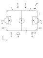
図1は、第1実施形態に係るマルチカメラシステム100の一例を示す図である。マルチカメラシステム100は、スポーツの試合が行われる試合場1に設置される。本実施形態では、スポーツとしてサッカーを例に挙げて説明するが、これに限定されず、例えばアメリカンフットボール、ラグビー、野球、陸上競技等の屋外競技や、バスケットボール、ハンドボール等の屋内競技等であってもよい。試合場1は、例えば地面2にフィールド3が設置される。フィールド3は、ライン4によって区画される。ライン4は、サイドライン5、エンドライン6、センターライン、ペナルティエリアライン、ゴールライン等を含む。試合場1は、予め位置座標が設定されている。位置座標は、例えばレーザセンサ等の公知の計測装置で計測することにより設定可能である。位置情報は、例えばX座標及びY座標を用いて表すことができる。図1に示すX軸は、例えばエンドライン6に平行に設定される。図1に示すY軸は、例えばサイドライン5に平行に設定される。なお、X軸及びY軸の設定については、上記に限定されない。
FIG. 1 is a diagram showing an example of the
図2は、マルチカメラシステム100の一例を示す機能ブロック図である。図1及び図2に示すように、マルチカメラシステム100は、カメラ10と、入力部20と、表示部30と、映像処理装置40とを備える。
FIG. 2 is a functional block diagram showing an example of the
カメラ10は、複数台設けられる。本実施形態では、例えば6台のカメラが設けられる場合を例に挙げて説明する。以下、6台のカメラ10を区別しないで説明する場合にはカメラ10と表記して説明し、6台のカメラ10を区別して説明する場合にはカメラ11〜16と異なる符号を付して説明する。なお、カメラ10の台数は、6台に限定されず、5台以下、又は7台以上であってもよい。複数のカメラ10は、少なくとも2台以上のカメラ10が試合場1の同一地点を画角に収めるように撮影する。
A plurality of
フィールド3に対して一方のサイドライン5aの外側には、カメラ11、12が配置される。フィールド3に対して他方のサイドライン5bの外側には、カメラ13、14が配置される。フィールド3に対して一方のエンドライン6aの外側には、カメラ15が配置される。フィールド3に対して他方のエンドライン6bの外側には、カメラ16が配置される。カメラ11〜16は、上記の試合場1の位置座標に対応付けられた位置座標を有している。カメラ11〜16の位置座標については、例えば後述の記憶部60に記憶させておくことができる。なお、上記カメラ11〜16の少なくとも1つ、又は上記カメラ11〜16とは別個のカメラを試合場1の上方に配置し、例えば試合場1を上方から撮影する構成であってもよい。
入力部20は、情報を入力するための所定の入力操作が可能である。入力部20としては、例えばタッチパネル等の入力装置が用いられる。この場合、入力部20は、後述の表示部30と一体で設けられる。なお、入力部20として、タッチパネルに加えて又はタッチパネルに代えて、ボタン、レバー、ダイヤル、スイッチ又は他の入力装置が用いられてもよい。入力部20は、所定の入力操作に応じた指示信号を出力する。
The
表示部30は、液晶パネル等の表示パネルを有する。表示部30は、文字及び画像を含む各種情報を表示する。表示部30は、例えば、各カメラ10によって撮影された映像や、入力部20によりタッチ操作を行うための入力操作用画像等を表示可能である。なお、上記の入力部20は、タッチパネルの表面のうち表示部30に表示される入力操作用の画像に対応する領域にタッチ操作が行われた場合、タッチ操作が行われた領域の位置情報を含む所定の指示信号を出力する。
The
映像処理装置40は、カメラ10によって撮影された映像を表示部30に表示させる映像表示処理を行う。映像処理装置40は、図2に示すように、制御部50と、記憶部60とを有する。
The
制御部50は、カメラ10、入力部20及び表示部30の各部の制御を行う。制御部50は、CPU(Central Processing Unit)等の処理装置や、RAM(Random Access Memory)、ROM(Read Only Memory)等の記憶装置を有している。制御部50は、映像表示制御部51と、設定領域情報取得部52と、進入情報取得部53と、退出情報取得部54と、仮想直線設定部55と、映像選択部56と、ハイライト表示制御部57とを有する。
The
映像表示制御部51には、複数のカメラ10で撮影した映像情報が入力される。映像表示制御部51は、入力された映像情報を表示部30に出力し、映像として表示部30に並べて表示させる。また、映像表示制御部51は、入力された映像を記憶部60に記憶させる。この場合、映像表示制御部51は、各映像を撮影時刻等の時刻情報と対応付けて記憶部60に記憶させる。
Video information captured by a plurality of
図3は、表示部30に表示される映像の一例を示す図である。図3に示すように、本実施形態において、表示部30は、上記の6台のカメラ10で撮影した6つの映像70を並べて表示させる。以下、6つの映像70を区別しないで説明する場合には映像70と表記して説明し、6つの映像70を区別して説明する場合には、映像71〜76と異なる符号を付して説明する。表示部30は、2つ以上であってもよい。
FIG. 3 is a diagram showing an example of an image displayed on the
設定領域情報取得部52は、表示部30に表示される複数の映像70内の一部に所定の設定領域が設定された場合、設定領域の範囲を示す設定領域情報を取得する。
When a predetermined setting area is set in a part of a plurality of
図4は、設定領域の一例を模式的に示す図である。図4に示すように、設定領域Aは、映像70内の一部に設定される。設定領域Aは、ユーザが入力部20により入力可能である。例えば、ユーザが入力部20により直接映像70内に設定領域Aを描画して設定してもよいし、予め設定された形状からユーザが選択してもよい。また、設定領域Aの形状が円形、楕円形、三角形、矩形等に予め設定されている場合、中心位置と設定領域Aの寸法(径、一辺の長さ等)とを入力部20等によりユーザに指定させることで、指定の中心位置を中心とする範囲に指定の寸法を有する設定領域Aを設定することができる。
FIG. 4 is a diagram schematically showing an example of a setting area. As shown in FIG. 4, the setting area A is set in a part of the
設定領域情報取得部52は、映像70内に設定領域Aが設定された場合、設定領域Aの範囲を示す設定領域情報を算出する。設定領域情報は、例えば図1に示す座標系のX及びYの2つの変数により、平面上の領域を示す関数として求めることができる。例えば、設定領域情報取得部52は、画像処理等により映像70内における設定領域Aの外郭線の位置と、試合場1に設定される位置座標とに基づいて、設定領域情報を算出する。なお、設定領域情報取得部52は、設定領域Aを閉じた領域として設定する。したがって、設定領域情報取得部52は、例えばユーザによって描画された領域等が閉じていない領域である場合、直線又は曲線を補うことで閉じた領域として設定してもよい。また、設定領域情報取得部52は、設定領域Aの重心位置Gを算出する。設定領域情報取得部52は、算出した設定領域情報及び重心位置Gを例えば記憶部60に記憶させる。
When the setting area A is set in the
進入情報取得部53は、映像70内において設定領域Aに選手が進入した場合、設定領域Aに最初に進入した選手である特定選手の進入時刻及び進入位置を含む進入情報を取得する。退出情報取得部54は、特定選手が設定領域Aから退出した場合、特定選手が退出した退出時刻及び退出位置を含む退出情報を取得する。
When a player enters the set area A in the
図5は、特定選手Pが設定領域Aに進入した後、設定領域Aから退出する場合の例を示している。進入情報取得部53は、選手が設定領域Aに進入したか否かを判定し、選手が設定領域Aに進入した場合、最初に設定領域Aに進入した選手を特定選手Pとして検出する。なお、進入情報取得部53は、特定選手Pを検出した後は、選手が設定領域Aに進入したか否かの判定を行わなくてもよい。また、進入情報取得部53は、特定選手Pが設定領域Aに進入した進入時刻と、進入位置Iの位置情報とを求める。進入情報取得部53は、進入時刻として、各映像70に対応付けられた時刻情報を求める。これにより、進入時刻と、映像70における時刻との間が対応付けされる。なお、進入情報取得部53は、取得した進入時刻と映像70における時刻とを対応付けるタグ情報を別途生成してもよい。進入情報取得部53は、進入位置Iの位置情報として、X座標及びY座標を算出する。進入情報取得部53は、取得した進入情報を記憶部60に記憶させる。進入情報取得部53は、特定選手P以外の選手が設定領域Aに進入する場合には、進入情報を算出する動作を行わない。
FIG. 5 shows an example in which the specific player P enters the set area A and then exits from the set area A. The approach
また、退出情報取得部54は、特定選手Pが設定領域Aから退出した場合、退出時刻と、退出位置Eの位置情報とを求める。退出情報取得部54は、退出時刻として、各映像70に対応付けられた時刻を求める。これにより、退出時刻と、映像70における時刻とが対応付けされる。なお、退出情報取得部54は、取得した退出時刻と映像70における時刻とを対応付けるタグ情報を別途生成してもよい。退出情報取得部54は、退出位置Eの位置情報として、X座標及びY座標を算出する。退出情報取得部54は、取得した退出情報を記憶部60に記憶させる。退出情報取得部54は、特定選手P以外の選手が設定領域Aから退出する場合には、退出情報を求める動作を行わない。
Further, when the specific player P exits from the set area A, the exit
仮想直線設定部55は、進入情報及び退出情報のうち少なくとも一方に基づいて、設定領域Aを通過する仮想直線を設定する。図6は、仮想直線の一設定例を示す図である。図6に示すように、仮想直線設定部55は、設定領域Aを通過する仮想直線Lを設定する。仮想直線設定部55は、例えば、設定領域Aの重心位置Gと進入位置Iとを結ぶ線分IGと、重心位置Gと退出位置Eとを結ぶ線分EGとがなす角IGEの二等分線を仮想直線Lとして設定することができる。この仮想直線Lを設定する場合、仮想直線設定部55は、進入位置Iと重心位置Gとを結ぶ線分と、退出位置Eと重心位置Gとを結ぶ線分とを設定し、設定した線分同士がなす角の二等分線を求める。仮想直線Lの設定例としては、これに限定されない。
The virtual straight
映像選択部56は、仮想直線の位置と複数のカメラ10の位置とに基づいて、表示部30に表示された複数の映像70から1つ以上の映像70を選択する。映像選択部56は、例えば、複数のカメラ10のうち仮想直線Lとの距離が短い順に1つ以上のカメラ10を選択してもよい。また、映像選択部56は、複数のカメラ10のうち、カメラ10の光軸と仮想直線Lとのなす角度が小さい順に1つ以上のカメラ10を選択してもよい。映像選択部56は、検出したカメラ10により撮影された映像70を選択する。
The
ハイライト表示制御部57は、表示部30に表示される複数の映像のうち映像選択部56が選択した1つ以上の映像に対してハイライト表示を行う。
The highlight
記憶部60は、例えばハードディスクドライブ、ソリッドステートドライブ等のストレージを有している。なお、記憶部60として、リムーバブルディスク等の外部記憶媒体が用いられてもよい。記憶部60は、映像処理のオペレーティングシステムや、カメラ10、入力部20及び表示部30の動作を制御するための各種プログラム、映像処理装置40において処理を行うための各種プログラム及びデータ等を記憶する。
The
また、記憶部60は、本実施形態に係る映像処理プログラムを記憶する。この映像処理プログラムは、複数のカメラ10で撮影した試合場の映像を表示部30に並べて表示させる処理と、表示部30に表示される複数の映像70内の一部に所定の設定領域が設定された場合、設定領域の範囲を示す設定領域情報を取得する処理と、映像70内において設定領域に選手が進入した場合、最初に進入した選手の進入時刻及び進入位置を含む進入情報を取得する処理と、設定領域に最初に進入した選手が設定領域から退出した場合、選手が退出した退出時刻及び退出位置を含む退出情報を取得する処理と、進入情報及び退出情報のうち少なくとも一方に基づいて、設定領域を通過する仮想直線を設定する処理と、仮想直線の位置と複数のカメラ10の位置とに基づいて、表示部30に表示された複数の映像70から1つ以上の映像70を選択する処理とを映像処理装置40に実行させる。
In addition, the
また、記憶部60は、映像記憶部61と、設定領域情報記憶部62と、進入情報記憶部63と、退出情報記憶部64と、ハイライト表示情報記憶部65と、選手情報記憶部66とを有する。
Further, the
映像記憶部61は、映像表示制御部51から出力された映像情報が入力される。映像記憶部61は、入力された映像情報を記憶する。映像記憶部61は、例えば映像情報を時刻情報と対応付けて記憶する。
The
設定領域情報記憶部62は、設定領域情報取得部52で取得された設定領域情報が入力される。設定領域情報記憶部62は、入力された設定領域情報を記憶する。
The setting area
進入情報記憶部63は、進入情報取得部53で取得された進入情報が入力される。進入情報記憶部63は、入力された進入情報を記憶する。
The approach
退出情報記憶部64は、退出情報取得部54で取得された退出情報が入力される。退出情報記憶部64は、入力された退出情報を記憶する。
The exit
ハイライト表示情報記憶部65は、表示部30に表示させるハイライト表示の表示データ及び表示プログラム等を記憶する。
The highlight display
選手情報記憶部66は、試合場1で行われる試合に参加する選手を識別するための選手情報を記憶する。選手情報は、例えば選手が所属するチーム、ポジション、背番号等の所属情報や、顔、身長、体重等の身体情報等が挙げられる。また、選手情報記憶部66は、設定領域Aに最初に進入した特定選手についての情報を記憶する。
The player
図7は、記憶部60に記憶される情報の一例を示すデータテーブルである。図7に示すように、記憶部60には、例えばユーザにより設定された複数の設定領域A1、A2、A3、…、が記憶されている。記憶部60は、設定領域情報記憶部62に記憶される設定領域情報と、進入情報記憶部63に記憶される進入情報(進入時刻、進入位置)と、退出情報記憶部64に記憶される退出情報(退出時刻、退出位置)と、選手情報記憶部66に記憶される特定選手とを対応付けて記憶する。なお、記憶部60は、進入時刻と映像70の時刻とを対応付けるタグ情報や、退出時刻と映像70の時刻とを対応付けるタグ情報等のタグ情報を記憶してもよい。
FIG. 7 is a data table showing an example of information stored in the
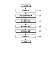
次に、上記のように構成されたマルチカメラシステム100の動作を説明する。以下の説明では、複数のカメラ10により試合場1における試合を撮影し、撮影した映像を映像記憶部61に記憶させた後、映像記憶部61に記憶された映像を表示部30に再生表示させる場合を例に挙げるが、これに限定されない。図8は、本実施形態に係るマルチカメラシステム100の動作の一例を示すフローチャートである。図8に示すように、映像表示制御部51は、複数のカメラ10で撮影された映像を映像記憶部61から取得し、表示部30に表示させる(ステップS10)。
Next, the operation of the
次に、設定領域情報取得部52は、表示部30に表示される複数の映像70内の一部に所定の設定領域Aが設定された場合、設定領域Aの位置を示す設定領域情報を取得する(ステップS20)。ステップS20において、設定領域情報取得部52は、表示部30に表示される複数の映像70に設定領域Aが入力されたか否かを判定する。設定領域情報取得部52は、入力部20により設定領域Aが入力されたと判定した場合、入力された設定領域Aの範囲を示す位置情報を設定領域情報として取得する。
Next, when the predetermined setting area A is set in a part of the plurality of
設定領域情報が取得された後、進入情報取得部53は、映像70内において設定領域Aに選手が進入した場合、最初に進入した特定選手の進入時刻及び進入位置を含む進入情報を取得する(ステップS30)。ステップS30において、進入情報取得部53は、例えば画像処理等により、設定領域Aに選手が進入したか否かを判定する。進入情報取得部53は、設定領域Aに選手が最初に進入したことを判定した場合、最初に進入した選手を特定選手Pとして検出する。進入情報取得部53は、画像処理等により特定選手Pの顔、背番号等の情報を抽出し、選手情報記憶部66に記憶された選手情報と照合させることにより、特定選手Pの情報を取得する。また、進入情報取得部53は、特定選手Pが設定領域Aに進入した進入時刻、進入位置を含む進入情報を取得する。
After the set area information is acquired, the approach
特定選手が設定領域Aに進入した後、特定選手が設定領域Aから退出した場合、退出情報取得部54は、特定選手が退出した退出時刻及び退出位置を含む退出情報を取得する(ステップS40)。ステップS40において、退出情報取得部54は、例えば画像処理等により、設定領域Aから特定選手が退出したか否かを判定する。退出情報取得部54は、特定選手が設定領域Aから退出したことを判定した場合、特定選手が設定領域Aから退出した退出時刻、退出位置を含む退出情報を取得する。
When the specific player leaves the set area A after the specific player enters the set area A, the exit
次に、仮想直線設定部55は、進入情報及び退出情報のうち少なくとも一方に基づいて設定領域Aを通過する仮想直線Lを設定する(ステップS50)。本実施形態において、仮想直線設定部55は、進入位置Iと退出位置Eとを用いて仮想直線Lの設定を行う。このため、ステップS50において、仮想直線設定部55は、まず、特定選手が設定領域Aから退出したか否かを判定し、特定選手が設定領域Aから退出した場合、仮想直線Lの設定を行う。この場合、仮想直線設定部55は、設定領域Aの重心位置Gと進入位置Iとを結ぶ線分IGと、重心位置Gと退出位置Eとを結ぶ線分EGとがなす角IGEの二等分線を仮想直線Lとして設定する。
Next, the virtual straight
映像選択部56は、仮想直線Lの位置と複数のカメラ10の位置とに基づいて、表示部30に表示された複数の映像70から1つ以上の映像70を選択する(ステップS60)。ステップS60において、映像選択部56は、例えば複数のカメラ10のうち仮想直線Lとの距離が最も短いカメラ10を選択する。そして、映像選択部56は、検出したカメラ10により撮影された映像70を選択する。
The
図9は、試合場1における仮想直線Lの位置を示す図である。図9に示すように、本実施形態において、仮想直線Lは、例えば設定領域Aの重心位置Gを通過し、カメラ14上に重なる位置に設定されている。この場合、映像選択部56は、例えば仮想直線Lとの距離が最も短いカメラ14を選択する。そして、映像選択部56は、選択したカメラ14により撮影された映像74を選択する。
FIG. 9 is a diagram showing the position of the virtual straight line L in the game field 1. As shown in FIG. 9, in the present embodiment, the virtual straight line L is set at a position where it passes through, for example, the center of gravity position G of the setting area A and overlaps with the
映像74が選択された場合、映像表示制御部51は、映像74のうち、例えば特定選手Pが設定領域Aに進入した進入時刻から、特定選手Pが設定領域Aから退出した退出時刻までのシーンを表示部30に表示させる。映像表示制御部51は、進入情報記憶部63に記憶される進入時刻及び退出情報記憶部64に記憶される退出時刻と、映像記憶部61に記憶される映像74の時刻とを対応させることにより、映像74のうち進入時刻から退出時刻までのシーンを抽出する。そして、映像表示制御部51は、抽出シーンを表示部30に表示させる。
When the
抽出シーンを表示する場合、ハイライト表示制御部57は、抽出シーンに対してハイライト表示を行う。ハイライト表示制御部57は、ハイライト表示情報記憶部65に記憶された表示データを選択して表示させたり、表示プログラム等を実行したりすることで、ハイライト表示を行う。この処理により、表示部30は、映像選択部56によって選択された映像74のうち、進入時刻から退出時刻までの抽出シーンをハイライト表示により表示する。
When displaying the extracted scene, the highlight
図10は、ハイライト表示の一例を示す図である。図10に示すように、本実施形態においては、選択した映像74を他の映像70(71〜73、75、76)に比べて表示部30に大きく表示させている。なお、ハイライト表示の例としては、これに限定されるものではなく、映像70の外縁を目立たせる表示であってもよいし、選択した映像74を指し示すアイコン等を表示させてもよい。
FIG. 10 is a diagram showing an example of highlight display. As shown in FIG. 10, in the present embodiment, the selected
以上のように、本実施形態に係る映像処理装置40は、複数のカメラ10で撮影した試合場1の映像70を表示部30に並べて表示させる映像表示制御部51と、表示部30に表示される複数の映像70内の一部に所定の設定領域Aが設定された場合、設定領域Aの位置を示す設定領域情報を取得する設定領域情報取得部52と、映像70内において設定領域Aに選手が進入した場合、最初に進入した特定選手の進入時刻及び進入位置を含む進入情報を取得する進入情報取得部53と、特定選手が設定領域Aから退出した場合、特定選手が退出した退出時刻及び退出位置を含む退出情報を取得する退出情報取得部54と、進入情報及び退出情報のうち少なくとも一方に基づいて、設定領域Aを通過する仮想直線Lを設定する仮想直線設定部55と、仮想直線Lの位置と複数のカメラ10の位置とに基づいて、表示部30に表示された複数の映像70から1つ以上の映像70を選択する映像選択部56とを備える。
As described above, the
この映像処理装置40は、特定選手が設定領域Aに進入及び退出した場合、進入情報及び退出情報の少なくとも一方に基づいて1つ以上の映像70を自動的に選択するため、特定選手Pの動きが判別しやすい映像70を短時間で選択することができる。これにより、表示部30に表示される複数の映像70から特定選手の動きが判別しやすい所定の映像70を選択する時間を短縮化できる。
When the specific player enters and exits the setting area A, the
また、本実施形態に係る映像処理装置40において、映像表示制御部51は、映像選択部56により選択された映像74のうち進入時刻から退出時刻までのシーンを表示部30に表示させるため、映像74のうちユーザの所望のシーンを抽出して表示させることができる。
Further, in the
また、本実施形態に係る映像処理装置40は、表示部30に表示されるシーンに対してハイライト表示を行うハイライト表示制御部57を更に備えるため、映像74の抽出シーンを容易にユーザに見つけさせることができる。これにより、表示部30に表示される複数の映像70の中からユーザが映像74の抽出シーンを探し当てる時間を短縮させることができる。
Further, since the
また、本実施形態に係る映像処理装置40において、仮想直線設定部55は、設定領域Aの重心位置Gと進入位置Iとを結ぶ線分と、重心位置Gと退出位置Eとを結ぶ線分とがなす角の二等分線を仮想直線Lとして設定する。これにより、特定選手Pが設定領域Aに進入してから退出するまでの動きを好適な方向から撮影したカメラ10を選択することができる。
Further, in the
また、本実施形態に係る映像処理装置40において、映像70、設定領域情報、進入情報及び退出情報を記憶する記憶部60を備えるため、外部の記憶部等を用いなくても、制御部50と連携した処理を高速で安定的に行うことが可能となる。
Further, since the
本発明の技術範囲は上記実施形態に限定されるものではなく、本発明の趣旨を逸脱しない範囲で適宜変更を加えることができる。例えば、上記した実施形態において、仮想直線設定部55は、設定領域Aの重心位置Gと進入位置Iとを結ぶ線分と、重心位置Gと退出位置Eとを結ぶ線分とがなす角IGEの二等分線を仮想直線Lとして設定する態様を例に挙げて説明したが、これに限定されない。
The technical scope of the present invention is not limited to the above-described embodiment, and modifications can be made as appropriate without departing from the spirit of the present invention. For example, in the above-described embodiment, the virtual straight
図11は、変形例に係る仮想直線の設定動作を示す図である。図11に示すように、仮想直線設定部55は、進入位置Iと退出位置Eとを結ぶ直線を仮想直線LAとして設定してもよい。この場合、特定選手Pが移動する方向の前方に配置されるカメラ10を選択することができる。
FIG. 11 is a diagram showing a setting operation of a virtual straight line according to a modified example. As shown in FIG. 11, the virtual straight
図12は、変形例に係る仮想直線の設定動作を示す図である。図12に示すように、進入情報取得部53は、進入情報として、特定選手Pが設定領域Aに進入する進入方向DBを取得する。そして、仮想直線設定部55は、進入位置Iを通過し、進入方向DBに平行な直線を仮想直線LBとして設定する。この場合、特定選手Pが設定領域Aに進入する進入方向の前方に配置されるカメラ10を選択することができる。
FIG. 12 is a diagram showing a setting operation of a virtual straight line according to a modified example. As shown in FIG. 12, the approach
図13は、変形例に係る仮想直線の設定動作を示す図である。図13に示すように、退出情報取得部54は、退出情報として、特定選手Pが設定領域Aから退出する退出方向DCを取得する。そして、仮想直線設定部55は、退出位置Eを通過し、退出方向DCに平行な直線を仮想直線LCとして設定する。この場合、特定選手Pが設定領域Aから退出する退出方向の前方に配置されるカメラ10を選択することができる。
FIG. 13 is a diagram showing a setting operation of a virtual straight line according to a modified example. As shown in FIG. 13, the exit
また、上記した実施形態において、仮想直線設定部55は、仮想直線Lが重心位置Gに対して両側に延びる場合を例に挙げて説明したが、これに限定されない。例えば、仮想直線設定部55は、重心位置Gから角IGEの角度が広角となる側にのみ延びるように仮想直線Lを設定してもよい。また、仮想直線設定部55は、重心位置Gから角IGEの角度が狭角となる側にのみ延びるように仮想直線Lを設定してもよい。なお、仮想直線設定部55は、異なる手法で求められる仮想直線Lを複数本同時に設定してもよい。
Further, in the above-described embodiment, the virtual straight
また、上記実施形態において、映像選択部56は、仮想直線Lに基づいて1つのカメラ10(カメラ14)を選択し、映像70(映像74)を選択する場合を例に挙げて説明したが、これに限定されない。例えば、映像選択部56は、仮想直線Lに基づいて複数のカメラ10を選択した後、選択した複数のカメラ10で撮影した映像70のうち特定選手Pを認識できる時間が長い映像70を選択してもよい。つまり、映像選択部56は、複数の映像70を段階的に選択することとし、その1つの選択段階において仮想直線Lを用いる態様であってもよい。
Further, in the above embodiment, the case where the
また、上記実施形態において、映像処理装置40は、映像選択部56により選択された映像74を映像表示制御部51により表示部30に表示させる態様を例に挙げて説明したが、これに限定されない。例えば、映像処理装置40は、映像選択部56により選択された映像74を表示部30に表示させることなく、記憶部60に記憶させてもよい。この場合、映像処理装置40は、進入時刻から退出時刻までのシーンを抽出して記憶部60に記憶させてもよい。
Further, in the above embodiment, the
また、上記実施形態において、進入情報取得部53は、設定領域Aに最初に進入した特定選手Pの進入情報を取得する態様を例に挙げて説明したが、これに限定されない。例えば、進入情報取得部53は、特定選手Pの進入情報に加えて、2番目に設定領域Aに進入した選手の進入情報を取得してもよい。
Further, in the above embodiment, the approach
同様に、上記実施形態において、退出情報取得部54は、設定領域Aから退出した特定選手Pの退出情報を取得する態様を例に挙げて説明したが、これに限定されない。例えば、退出情報取得部54は、特定選手Pの退出情報に加えて、2番目に設定領域Aに進入した選手が退出した場合の退出情報を取得してもよい。
Similarly, in the above-described embodiment, the exit
このように、進入情報取得部53及び退出情報取得部54は、複数の選手の進入情報及び退出情報を取得してもよい。この場合、仮想直線設定部55は、複数の選手の進入情報及び退出情報に基づいて仮想直線を設定する。この仮想直線は、1本であってもよいし、2本以上であってもよい。
In this way, the entry
映像選択部56は、仮想直線が2本以上の場合、2本以上の仮想直線に基づいて映像を選択することができる。この場合、1本の仮想直線毎に1つ以上の映像を選択してもよいし、複数の仮想直線毎に1つ以上の映像を選択してもよい。
When the number of virtual straight lines is two or more, the
A,A1,A2,A3…設定領域、E…退出位置、G…重心位置、I…進入位置、L,LA,LB,LC…仮想直線、P…特定選手、DB…進入方向、DC…退出方向、EG,IG…線分、1…試合場、2…地面、3…フィールド、4…ライン、5,5a,5b…サイドライン、6,6a,6b…エンドライン、10,11〜16…カメラ、20…入力部、30…表示部、40…映像処理装置、50…制御部、51…映像表示制御部、52…設定領域情報取得部、53…進入情報取得部、54…退出情報取得部、55…仮想直線設定部、56…映像選択部、57…ハイライト表示制御部、60…記憶部、61…映像記憶部、62…設定領域情報記憶部、63…進入情報記憶部、64…退出情報記憶部、65…ハイライト表示情報記憶部、66…選手情報記憶部、70,71〜76…映像、100…マルチカメラシステム。 A, A1, A2, A3 ... Setting area, E ... Exit position, G ... Center of gravity position, I ... Entry position, L, LA, LB, LC ... Virtual straight line, P ... Specific player, DB ... Entry direction, DC ... Exit Direction, EG, IG ... line, 1 ... game field, 2 ... ground, 3 ... field, 4 ... line, 5,5a, 5b ... sideline, 6,6a, 6b ... end line, 10,11-16 ... Camera, 20 ... Input unit, 30 ... Display unit, 40 ... Video processing device, 50 ... Control unit, 51 ... Video display control unit, 52 ... Setting area information acquisition unit, 53 ... Entrance information acquisition unit, 54 ... Exit information acquisition Unit, 55 ... Virtual straight line setting unit, 56 ... Video selection unit, 57 ... Highlight display control unit, 60 ... Storage unit, 61 ... Video storage unit, 62 ... Setting area information storage unit, 63 ... Entry information storage unit, 64 ... Exit information storage unit, 65 ... Highlight display information storage unit, 66 ... Player information storage unit, 70, 71-76 ... Video, 100 ... Multi-camera system.
Claims (5)
前記表示部に表示される複数の前記映像内の一部に所定の設定領域が設定された場合、前記設定領域の範囲を示す設定領域情報を取得する設定領域情報取得部と、
前記映像内において前記設定領域に複数の選手が進入した場合、進入した前記複数の選手の進入時刻及び進入位置を含む進入情報を前記設定領域に進入した選手毎に取得する進入情報取得部と、
前記複数の選手が前記設定領域から退出した場合、前記複数の選手が退出した退出時刻及び退出位置を含む退出情報を前記設定領域から退出した選手毎に取得する退出情報取得部と、
前記進入情報及び前記退出情報のうち少なくとも一方に基づいて、前記設定領域を通過する仮想直線を前記設定領域に進入した選手毎に設定する仮想直線設定部と、
前記仮想直線の位置と複数の前記カメラの位置とに基づいて、前記表示部に表示された複数の前記映像から前記仮想直線毎に1つ以上の前記映像を選択する映像選択部と
を備える映像処理装置。 An image display control unit that displays the images of the game field shot by multiple cameras side by side on the display unit,
When a predetermined setting area is set in a part of the plurality of images displayed on the display unit, a setting area information acquisition unit that acquires setting area information indicating the range of the setting area, and a setting area information acquisition unit.
When a plurality of athletes enter the set area in the video, an approach information acquisition unit that acquires approach information including the approach time and approach position of the plurality of athletes who have entered the set area for each athlete who has entered the set area.
When the plurality of athletes have exited from the set area, an exit information acquisition unit that acquires exit information including the exit time and exit position of the plurality of athletes for each player who has exited from the set area.
A virtual straight line setting unit that sets a virtual straight line passing through the set area for each player who has entered the set area based on at least one of the entry information and the exit information.
An image including a video selection unit that selects one or more of the images for each virtual straight line from a plurality of the images displayed on the display unit based on the positions of the virtual straight lines and the positions of the plurality of cameras. Processing equipment.
請求項1に記載の映像処理装置。 The video processing device according to claim 1, wherein the video display control unit displays a scene from the entry time to the exit time of the video selected by the video selection unit on the display unit.
複数の前記カメラで撮影した映像を表示可能な表示部と、
前記映像を処理する請求項1または請求項2に記載の映像処理装置と
を備えるマルチカメラシステム。 With multiple cameras that shoot the game field from different angles,
A display unit that can display images taken by multiple cameras,
A multi-camera system including the video processing apparatus according to claim 1 or 2, which processes the video.
前記表示部に表示される複数の前記映像内の一部に所定の設定領域が設定された場合、前記設定領域の範囲を示す設定領域情報を取得することと、
前記映像内において前記設定領域に複数の選手が進入した場合、進入した前記複数の選手の進入時刻及び進入位置を含む進入情報を前記設定領域に進入した選手毎に取得することと、
前記複数の選手が前記設定領域から退出した場合、前記複数の選手が退出した退出時刻及び退出位置を含む退出情報を前記設定領域から退出した選手毎に取得することと、
前記進入情報及び前記退出情報のうち少なくとも一方に基づいて、前記設定領域を通過する仮想直線を前記設定領域に進入した選手毎に設定することと、
前記仮想直線の位置と複数の前記カメラの位置とに基づいて、前記表示部に表示された複数の前記映像から前記仮想直線毎に1つ以上の前記映像を選択することと
を含む映像処理方法。 Displaying the video of the game field shot by multiple cameras side by side on the display,
When a predetermined setting area is set in a part of the plurality of images displayed on the display unit, the setting area information indicating the range of the setting area can be acquired.
When a plurality of athletes have entered the set area in the video, the approach information including the approach time and the approach position of the plurality of athletes who have entered is acquired for each athlete who has entered the set area.
When the plurality of players have left the set area, the exit information including the exit time and the exit position of the plurality of players has been acquired for each player who has left the set area.
Based on at least one of the entry information and the exit information, a virtual straight line passing through the set area is set for each player who has entered the set area.
An image processing method including selecting one or more of the images for each virtual line from a plurality of images displayed on the display unit based on the positions of the virtual straight lines and the positions of the plurality of cameras. ..
前記表示部に表示される複数の前記映像内の一部に所定の設定領域が設定された場合、前記設定領域の範囲を示す設定領域情報を取得する処理と、
前記映像内において前記設定領域に複数の選手が進入した場合、進入した前記複数の選手の進入時刻及び進入位置を含む進入情報を前記設定領域に進入した選手毎に取得する処理と、
前記複数の選手が前記設定領域から退出した場合、前記複数の選手が退出した退出時刻及び退出位置を含む退出情報を前記設定領域から退出した選手毎に取得する処理と、
前記進入情報及び前記退出情報のうち少なくとも一方に基づいて、前記設定領域を通過する仮想直線を前記設定領域に進入した選手毎に設定する処理と、
前記仮想直線の位置と複数の前記カメラの位置とに基づいて、前記表示部に表示された複数の前記映像から前記仮想直線毎に1つ以上の前記映像を選択する処理と
をコンピュータに実行させる映像処理プログラム。 The process of displaying the video of the game field shot by multiple cameras side by side on the display unit,
When a predetermined setting area is set in a part of the plurality of images displayed on the display unit, a process of acquiring setting area information indicating the range of the setting area and a process of acquiring the setting area information indicating the range of the setting area.
When a plurality of athletes have entered the set area in the video, the process of acquiring the approach information including the approach time and the approach position of the plurality of athletes who have entered the set area for each athlete who has entered the set area.
When the plurality of players have left the set area, a process of acquiring exit information including the exit time and the exit position of the plurality of players for each player who has left the set area.
A process of setting a virtual straight line passing through the set area for each player who has entered the set area based on at least one of the entry information and the exit information.
A computer is made to execute a process of selecting one or more of the images for each virtual line from a plurality of images displayed on the display unit based on the positions of the virtual straight lines and the positions of the plurality of cameras. Video processing program.
Priority Applications (1)
| Application Number | Priority Date | Filing Date | Title |
|---|---|---|---|
| JP2020154648A JP6965975B2 (en) | 2017-03-10 | 2020-09-15 | Video processing equipment, multi-camera system, video processing method, and video processing program |
Applications Claiming Priority (2)
| Application Number | Priority Date | Filing Date | Title |
|---|---|---|---|
| JP2017046007A JP6766707B2 (en) | 2017-03-10 | 2017-03-10 | Video processing equipment, multi-camera system, video processing method, and video processing program |
| JP2020154648A JP6965975B2 (en) | 2017-03-10 | 2020-09-15 | Video processing equipment, multi-camera system, video processing method, and video processing program |
Related Parent Applications (1)
| Application Number | Title | Priority Date | Filing Date |
|---|---|---|---|
| JP2017046007A Division JP6766707B2 (en) | 2017-03-10 | 2017-03-10 | Video processing equipment, multi-camera system, video processing method, and video processing program |
Publications (2)
| Publication Number | Publication Date |
|---|---|
| JP2020198652A JP2020198652A (en) | 2020-12-10 |
| JP6965975B2 true JP6965975B2 (en) | 2021-11-10 |
Family
ID=73649384
Family Applications (1)
| Application Number | Title | Priority Date | Filing Date |
|---|---|---|---|
| JP2020154648A Active JP6965975B2 (en) | 2017-03-10 | 2020-09-15 | Video processing equipment, multi-camera system, video processing method, and video processing program |
Country Status (1)
| Country | Link |
|---|---|
| JP (1) | JP6965975B2 (en) |
Family Cites Families (8)
| Publication number | Priority date | Publication date | Assignee | Title |
|---|---|---|---|---|
| JP2008244922A (en) * | 2007-03-28 | 2008-10-09 | Mitsubishi Electric Corp | Video generating method and video generating apparatus |
| JP5197516B2 (en) * | 2008-09-22 | 2013-05-15 | ヤフー株式会社 | Image configuration output apparatus, method and system |
| JP6267961B2 (en) * | 2012-08-10 | 2018-01-24 | パナソニック インテレクチュアル プロパティ コーポレーション オブ アメリカPanasonic Intellectual Property Corporation of America | Image providing method and transmitting apparatus |
| JP5915558B2 (en) * | 2013-01-30 | 2016-05-11 | カシオ計算機株式会社 | Image selection apparatus, image selection method, image distribution system, and program |
| GB2517730A (en) * | 2013-08-29 | 2015-03-04 | Mediaproduccion S L | A method and system for producing a video production |
| WO2015151095A1 (en) * | 2014-04-03 | 2015-10-08 | Pixellot Ltd. | Method and system for automatic television production |
| JP2016046642A (en) * | 2014-08-21 | 2016-04-04 | キヤノン株式会社 | Information processing system, information processing method, and program |
| BR112017007408A2 (en) * | 2014-10-10 | 2019-11-19 | Liverbarn Inc | system and method for optical tracking of players in sports stadiums |
-
2020
- 2020-09-15 JP JP2020154648A patent/JP6965975B2/en active Active
Also Published As
| Publication number | Publication date |
|---|---|
| JP2020198652A (en) | 2020-12-10 |
Similar Documents
| Publication | Publication Date | Title |
|---|---|---|
| JP6606985B2 (en) | Image processing method, image processing program, and image processing apparatus | |
| US20170171570A1 (en) | Information processing apparatus, information processing method, and computer-readable storage medium | |
| WO2018035821A1 (en) | Billiard ball striking assistance method, billiard ball striking assistance system, and portable electronic device | |
| JP6740930B2 (en) | Judgment auxiliary processing device, judgment auxiliary system, judgment auxiliary method and judgment auxiliary program | |
| JP7205201B2 (en) | DISPLAY METHOD, DISPLAY PROGRAM AND INFORMATION PROCESSING DEVICE | |
| JP6720587B2 (en) | Video processing device, video processing method, and video processing program | |
| TWI537872B (en) | Method for generating three-dimensional information from identifying two-dimensional images. | |
| JP6447515B2 (en) | Information processing apparatus, recording medium, and information processing method | |
| WO2014005561A1 (en) | Equipment using cameras for recording and displaying impact of the ball around the lines of the playing area | |
| US11823454B2 (en) | Method and apparatus for user interaction with a video stream | |
| US10025986B1 (en) | Method and apparatus for automatically detecting and replaying notable moments of a performance | |
| EP3517187B1 (en) | Sporting display and device method | |
| JP6965975B2 (en) | Video processing equipment, multi-camera system, video processing method, and video processing program | |
| CN107635627B (en) | Billiard ball hitting assisting method, billiard ball hitting assisting system and portable electronic equipment | |
| CN107710732A (en) | Shoot video camera, the method and system of golf sports | |
| JP6766707B2 (en) | Video processing equipment, multi-camera system, video processing method, and video processing program | |
| WO2016067553A1 (en) | Play segment extraction method and play segment extraction device | |
| EP3836012B1 (en) | A device, computer program and method for determining handball performed by a player | |
| KR101905848B1 (en) | Measuring device and measuring method for golf club and golf ball and computer readable recording medium having program the same | |
| JP2015217122A (en) | Image notification device, imaging device, image notification method, and image notification program | |
| KR20090046088A (en) | Virtual reality video-game system and playing method of the same | |
| KR101892514B1 (en) | Automatic score calculation system for billiard game using coordinate values | |
| JP6722610B2 (en) | Ball speed measuring system and ball speed measuring method | |
| KR101707626B1 (en) | Apparatus and method for comparing moving pictures | |
| KR101737587B1 (en) | Sports management apparatus and method |
Legal Events
| Date | Code | Title | Description |
|---|---|---|---|
| A621 | Written request for application examination |
Free format text: JAPANESE INTERMEDIATE CODE: A621 Effective date: 20200915 |
|
| A977 | Report on retrieval |
Free format text: JAPANESE INTERMEDIATE CODE: A971007 Effective date: 20210913 |
|
| TRDD | Decision of grant or rejection written | ||
| A01 | Written decision to grant a patent or to grant a registration (utility model) |
Free format text: JAPANESE INTERMEDIATE CODE: A01 Effective date: 20210921 |
|
| A61 | First payment of annual fees (during grant procedure) |
Free format text: JAPANESE INTERMEDIATE CODE: A61 Effective date: 20211004 |
|
| R150 | Certificate of patent or registration of utility model |
Ref document number: 6965975 Country of ref document: JP Free format text: JAPANESE INTERMEDIATE CODE: R150 |