JP6965518B2 - Drawing method, drawing device, and program - Google Patents
Drawing method, drawing device, and program Download PDFInfo
- Publication number
- JP6965518B2 JP6965518B2 JP2017005990A JP2017005990A JP6965518B2 JP 6965518 B2 JP6965518 B2 JP 6965518B2 JP 2017005990 A JP2017005990 A JP 2017005990A JP 2017005990 A JP2017005990 A JP 2017005990A JP 6965518 B2 JP6965518 B2 JP 6965518B2
- Authority
- JP
- Japan
- Prior art keywords
- area
- graph
- unit
- pattern
- color
- Prior art date
- Legal status (The legal status is an assumption and is not a legal conclusion. Google has not performed a legal analysis and makes no representation as to the accuracy of the status listed.)
- Active
Links
Images


Classifications
-
- G—PHYSICS
- G06—COMPUTING; CALCULATING OR COUNTING
- G06T—IMAGE DATA PROCESSING OR GENERATION, IN GENERAL
- G06T17/00—Three dimensional [3D] modelling, e.g. data description of 3D objects
- G06T17/20—Finite element generation, e.g. wire-frame surface description, tesselation
-
- G—PHYSICS
- G06—COMPUTING; CALCULATING OR COUNTING
- G06T—IMAGE DATA PROCESSING OR GENERATION, IN GENERAL
- G06T19/00—Manipulating 3D models or images for computer graphics
- G06T19/20—Editing of 3D images, e.g. changing shapes or colours, aligning objects or positioning parts
-
- G—PHYSICS
- G06—COMPUTING; CALCULATING OR COUNTING
- G06F—ELECTRIC DIGITAL DATA PROCESSING
- G06F17/00—Digital computing or data processing equipment or methods, specially adapted for specific functions
- G06F17/10—Complex mathematical operations
- G06F17/17—Function evaluation by approximation methods, e.g. inter- or extrapolation, smoothing, least mean square method
-
- G—PHYSICS
- G06—COMPUTING; CALCULATING OR COUNTING
- G06F—ELECTRIC DIGITAL DATA PROCESSING
- G06F3/00—Input arrangements for transferring data to be processed into a form capable of being handled by the computer; Output arrangements for transferring data from processing unit to output unit, e.g. interface arrangements
- G06F3/01—Input arrangements or combined input and output arrangements for interaction between user and computer
- G06F3/03—Arrangements for converting the position or the displacement of a member into a coded form
- G06F3/033—Pointing devices displaced or positioned by the user, e.g. mice, trackballs, pens or joysticks; Accessories therefor
- G06F3/0354—Pointing devices displaced or positioned by the user, e.g. mice, trackballs, pens or joysticks; Accessories therefor with detection of 2D relative movements between the device, or an operating part thereof, and a plane or surface, e.g. 2D mice, trackballs, pens or pucks
- G06F3/03547—Touch pads, in which fingers can move on a surface
-
- G—PHYSICS
- G06—COMPUTING; CALCULATING OR COUNTING
- G06F—ELECTRIC DIGITAL DATA PROCESSING
- G06F7/00—Methods or arrangements for processing data by operating upon the order or content of the data handled
- G06F7/38—Methods or arrangements for performing computations using exclusively denominational number representation, e.g. using binary, ternary, decimal representation
- G06F7/48—Methods or arrangements for performing computations using exclusively denominational number representation, e.g. using binary, ternary, decimal representation using non-contact-making devices, e.g. tube, solid state device; using unspecified devices
- G06F7/57—Arithmetic logic units [ALU], i.e. arrangements or devices for performing two or more of the operations covered by groups G06F7/483 – G06F7/556 or for performing logical operations
-
- G—PHYSICS
- G06—COMPUTING; CALCULATING OR COUNTING
- G06T—IMAGE DATA PROCESSING OR GENERATION, IN GENERAL
- G06T11/00—2D [Two Dimensional] image generation
- G06T11/20—Drawing from basic elements, e.g. lines or circles
- G06T11/206—Drawing of charts or graphs
-
- G—PHYSICS
- G06—COMPUTING; CALCULATING OR COUNTING
- G06T—IMAGE DATA PROCESSING OR GENERATION, IN GENERAL
- G06T15/00—3D [Three Dimensional] image rendering
- G06T15/10—Geometric effects
-
- G—PHYSICS
- G06—COMPUTING; CALCULATING OR COUNTING
- G06T—IMAGE DATA PROCESSING OR GENERATION, IN GENERAL
- G06T2219/00—Indexing scheme for manipulating 3D models or images for computer graphics
- G06T2219/20—Indexing scheme for editing of 3D models
- G06T2219/2012—Colour editing, changing, or manipulating; Use of colour codes
Landscapes
- Engineering & Computer Science (AREA)
- Physics & Mathematics (AREA)
- General Physics & Mathematics (AREA)
- Theoretical Computer Science (AREA)
- General Engineering & Computer Science (AREA)
- Software Systems (AREA)
- Computer Graphics (AREA)
- Pure & Applied Mathematics (AREA)
- Computational Mathematics (AREA)
- Mathematical Optimization (AREA)
- Mathematical Analysis (AREA)
- Mathematical Physics (AREA)
- Data Mining & Analysis (AREA)
- Geometry (AREA)
- Architecture (AREA)
- Computer Hardware Design (AREA)
- Algebra (AREA)
- Computing Systems (AREA)
- Databases & Information Systems (AREA)
- Human Computer Interaction (AREA)
- Image Generation (AREA)
- Processing Or Creating Images (AREA)
- User Interface Of Digital Computer (AREA)
Description
本発明は、図形を描画するための描画方法、描画装置及びその制御プログラムに関する。 The present invention relates to a drawing method for drawing a figure, a drawing device, and a control program thereof.
従来の図形描画装置において、2次元座標系に、複数の不等式に各々対応するグラフを描画する際に、各不等式の領域が重なる重複部分を識別可能にカラー表示することが考えられている(例えば、特許文献1参照。)。 In a conventional graphic drawing device, when drawing a graph corresponding to a plurality of inequalities in a two-dimensional coordinate system, it is considered to display the overlapping portion where the regions of the inequalities overlap in a color display so as to be distinguishable (for example). , Patent Document 1).
本発明が解決しようとする課題は、表示装置の画面に設定される3次元座標系に複数の面を描画したときに、複数の面の少なくとも一部の領域が互いに重なっている、または、略重なっていることを分かり易く表示することが可能な描画方法、描画装置、及びその制御プログラムを提供することである。 The problem to be solved by the present invention is that when a plurality of surfaces are drawn on a three-dimensional coordinate system set on the screen of a display device, at least a part of the regions of the plurality of surfaces overlap each other or are omitted. It is an object of the present invention to provide a drawing method, a drawing device, and a control program thereof capable of displaying the overlapping in an easy-to-understand manner.
本発明に係る描画方法は、描画装置の制御部により、3次元座標系において、第1の面の少なくとも一部の領域と第2の面の少なくとも一部の領域とが互いに略同一であった場合、前記第1の面に関連付けられた第1の描画パターンと前記第2の面に関連付けられた第2の描画パターンとのそれぞれを、前記第1の面の前記少なくとも一部の領域または前記第2の面の前記少なくとも一部の領域において、前記第1の描画パターンおよび前記第2の描画パターンがランダムに又は規則正しく配されるように、前記第1の面の前記少なくとも一部の領域または前記第2の面の前記少なくとも一部の領域を形成する複数の単位描画領域の何れかに割り当てて、2以上の前記単位描画領域を、各単位描画領域に割り当てた描画パターンを使って描画することによって、前記第1の面または前記第2の面の前記少なくとも一部の領域を描画する、ことを特徴としている。 In the drawing method according to the present invention, at least a part of the area of the first surface and at least a part of the area of the second surface are substantially the same as each other in the three-dimensional coordinate system by the control unit of the drawing device. In the case, each of the first drawing pattern associated with the first surface and the second drawing pattern associated with the second surface is each of the at least a part of the region of the first surface or the said. In the at least a part of the area of the first surface or in the at least a part of the area of the first surface so that the first drawing pattern and the second drawing pattern are randomly or regularly arranged. assigned to one of a plurality of unit drawing areas forming the at least a partial area of the second surface, two or more the unit drawing area is drawn with a drawing pattern assigned to each unit drawing area This is characterized in that the first surface or at least a part of the area of the second surface is drawn.
本発明によれば、表示装置の画面に設定される3次元座標系に複数の面を描画したときに、複数の面の少なくとも一部の領域が互いに重なっている、または、略重なっていることを分かり易く表示することが可能になる。 According to the present invention, when a plurality of surfaces are drawn in a three-dimensional coordinate system set on the screen of a display device, at least a part of the regions of the plurality of surfaces overlap each other or substantially overlap each other. Can be displayed in an easy-to-understand manner.
以下図面により本発明の実施の形態について説明する。 Hereinafter, embodiments of the present invention will be described with reference to the drawings.
図1は、本発明の実施形態に係る図形描画装置10の外観構成を示す正面図であり、同図(A)は図形描画装置10をグラフ関数電卓10Fとして実施した場合を示す図、同図(B)は図形描画装置10をタブレット端末10Tとして実施した場合を示す図である。
FIG. 1 is a front view showing an external configuration of a
前記図形描画装置10は、前記グラフ関数電卓10Fやタブレット端末10Tとして構成する他、3次元座標系に図形を描画する3Dグラフ(図形)表示制御プログラムが実装されたパーソナルコンピュータ、スマートフォン、携帯電話機、タッチパネル式PDA(personal digital assistants)、電子ブック、携帯ゲーム機等として構成することができる。
The
なお、前記グラフ関数電卓10Fのような物理的なキー(ボタン)が実装されていない前記タブレット端末10Tのような図形描画装置10は、前記グラフ関数電卓10Fのキーと同様なソフトウェアキーボードを表示出力部12の画面に表示し、このソフトウェアキーボードに対する入力操作に応じて処理を実行する。
The
前記グラフ関数電卓10Fは、その携帯性の必要からユーザが片手で十分把持し片手で操作可能な小型サイズからなり、このグラフ関数電卓10の本体正面にはキー入力部11および表示出力部12が設けられる。
The graph
前記キー入力部11には、数値や数式を入力したり計算の実行を指示したりするための数値・演算記号キー群111、各種の関数を入力したりメモリ機能を立ち上げたりするための関数機能キー群112、各種動作モードのメニュー画面を表示させたり動作モードの設定を指示したりするためのモード設定キー群113、前記表示出力部12の表示画面内に表示画面の下端に沿って表示された各種の機能を1回のキー操作で立ち上げるためのファンクションキー群114、前記表示出力部12に表示されたカーソルの移動操作やデータ項目の選択操作などを行うためのカーソルキー115が備えられる。
In the
前記数値・演算記号キー群111としては、[0]〜[9](数値)キー、[+][−][×][÷](四則記号)キー、[EXE](実行)キー、[AC](クリア)キーなどが配列される。
The numerical / arithmetic
前記関数機能キー群112としては、[log](対数)キー、[sin](サイン)キー、[cos](コサイン)キー、[tan](タンジェント)キーなどが配列される。
As the function
前記モード設定キー群113としては、[MENU](メニュー)キー、[SHIFT](シフト)キー、[OPTN](オプション)キーなどが配列される。
As the mode setting
前記ファンクションキー群114としては、[F1]キー〜[F6]キーが配列される。
As the
なお、前記数値・演算記号キー群111、関数機能キー群112、前記モード設定キー群113、前記ファンクションキー群114のキーは、[SHIFT]キーが操作された後に続けて操作されることで、そのキートップに記載されたキー機能ではなく、そのキーの上方に記載されたキーとして機能できるようになっている。例えば、[SHIFT]キー操作後に[AC]キーが操作(以下、[SHIFT]+[AC]キーと記す。)されると[OFF](電源オフ)キーとなる。[SHIFT]+[MENU]キーは[SET UP](セットアップ)キー、[SHIFT]+[F3]キーは[V−Window](ビューウインドウ)キーとなる。
The keys of the numerical value / calculation
前記グラフ関数電卓10Fの表示出力部12は、ドットマトリクス型の液晶表示ユニットであり、入力操作を受け付け可能には構成されていない。前記タブレット端末10Tの表示出力部12は、その最外面にタッチパネルが一体化して設けられていて、入力操作を受け付け可能に構成されている。
The
図1(A)(B)は、入力を受け付けた3つの数式が、表示出力部12の画面に設定された3次元座標系内において、互いに全く同じ円柱を特定するものであった場合に、前記3次元座標系である3D空間(ビューウインドウ)Ad内で、これら3つの円柱に対応する3DグラフFC1,FC2,FC3が重なった状態の3DグラフFC123を前記表示出力部12の画面に描画して表示させた状態を示す。上蓋となる円の領域FCaと下蓋となる円の領域FCbとその間の側面の領域FCsとの各領域において、3つの3DグラフFC1,FC2,FC3にそれぞれ設定された描画パターンが単位描画領域毎にランダムに割り当てられている。3つの3DグラフFC1,FC2,FC3に設定された描画パターンは、塗りつぶし色が赤色R,青色B,緑色Gの各色であり、線色がいずれも黒色である。
1 (A) and 1 (B) show the case where the three mathematical formulas that have received the input specify exactly the same cylinders in the three-dimensional coordinate system set on the screen of the
これにより、前記複数の3Dグラフを描画するために入力された各数式とそのパラメータが同一である場合や、入力された各数式の表現が異なっているものの数学的には同等である場合、または、前記複数の3Dグラフの一部或いは全部の領域の前記3次元座標系内での位置が互いに略同一である場合には、複数の3Dグラフに関連付けられた複数の描画パターンのそれぞれを、前記略同一の領域に対応する複数の後述する単位描画領域の何れかに割り当て、前記複数の単位描画領域を、各単位描画領域に割り当てた描画パターンを使って描画する。これにより、この略同一の領域において、複数の3Dグラフが重なっていることを容易に知ることができる。 As a result, when each formula entered for drawing the plurality of 3D graphs and its parameters are the same, or when the expressions of the entered formulas are different but mathematically equivalent, or When the positions of a part or all the regions of the plurality of 3D graphs in the three-dimensional coordinate system are substantially the same as each other, each of the plurality of drawing patterns associated with the plurality of 3D graphs is described. Allocate to any of a plurality of unit drawing areas described later corresponding to substantially the same area, and the plurality of unit drawing areas are drawn using the drawing pattern assigned to each unit drawing area. As a result, it is possible to easily know that a plurality of 3D graphs overlap in this substantially the same region.
ここで、前記図形描画装置10における3Dグラフ描画処理の概略について説明する。
Here, the outline of the 3D graph drawing process in the
この3Dグラフ描画処理には、3Dグラフ(図形)の表面をポリゴン(グリッド)の集合としてモデル化する描画手法を用いる。 In this 3D graph drawing process, a drawing method is used in which the surface of a 3D graph (graphic) is modeled as a set of polygons (grids).
すなわち、3Dグラフ(図形)を描画するための数式とそのパラメータに従って、描画対象となる図形の面を構成する座標列が演算処理されて算出され、算出された座標列間を縦横に結ぶ線により細分割されて生成される各ポリゴン(グリッド)の領域(単位描画領域)を塗りつぶした面として描画することで、前記3Dグラフ(図形)を表示させる。 That is, according to the formula for drawing a 3D graph (figure) and its parameters, the coordinate strings constituting the surface of the figure to be drawn are calculated by arithmetic processing, and the calculated coordinate strings are connected vertically and horizontally by lines. The 3D graph (figure) is displayed by drawing the area (unit drawing area) of each polygon (grid) generated by subdividing as a filled surface.
例えば、図1に示すような円柱(円付図形)FC123の場合、3D空間Ad上での前記円柱FC123の一方の円(上蓋)FCaの円周を構成する座標列と、他方の円(下蓋)FCbの円周を構成する座標列とが演算処理されて算出される。また、前記算出された一方の円FCaに対応する座標列と他方の円FCbに対応する座標列とを結ぶ線を構成する座標列が、前記円柱FC123の側面FCsを構成する座標列として演算処理されて算出される。 For example, in the case of a cylinder (figure with a circle) FC123 as shown in FIG. 1, a coordinate sequence constituting the circumference of one circle (upper lid) FCa of the cylinder FC123 on the 3D space Ad and the other circle (bottom). Lid) The coordinate sequence constituting the circumference of FCb is calculated by arithmetic processing. Further, the coordinate sequence constituting the line connecting the calculated coordinate sequence corresponding to one circle FCa and the coordinate sequence corresponding to the other circle FCb is arithmetically processed as the coordinate sequence constituting the side surface FCs of the cylinder FC123. Is calculated.
そして、前記算出された一方の円FCaに対応する座標列と他方の円FCbに対応する座標列と円柱の側面FCsに対応する座標列の各座標の点を、前記一方の円FCa、他方の円FCb、側面Fsの順に描画することで、前記円柱(円付図形)FC123を表示させる。 Then, the points of the coordinate strings corresponding to the calculated one circle FCa, the coordinate strings corresponding to the other circle FCb, and the coordinate strings corresponding to the side surface FCs of the cylinder are set to the points of the one circle FCa and the other. By drawing the circle FCb and the side surface Fs in this order, the cylinder (figure with a circle) FC123 is displayed.
この際、前記一方と他方の円FCa,FCbについては、その中心の座標点と該当する円の円周に対応する各座標点との間を結ぶ放射状の線と、同円の円周の各座標点間を結ぶ線とにより分割されて生成される多数の三角形(グリッド(多角形))の集合で面が構成される。また、側面については、一方の円FCaの円周に対応する各座標点と他方の円FCbの円周に対応する各座標点とを結ぶ線により分割されて生成される多数の四角形(グリッド(多角形))の集合で面が構成される。 At this time, with respect to the one and the other circles FCa and FCb, a radial line connecting the coordinate point at the center and each coordinate point corresponding to the circumference of the corresponding circle and each of the circumferences of the same circle. A surface is composed of a set of a large number of triangles (grids) generated by being divided by a line connecting coordinate points. As for the side surface, a large number of quadrangles (grid (grid)) are generated by being divided by a line connecting each coordinate point corresponding to the circumference of one circle FCa and each coordinate point corresponding to the circumference of the other circle FCb. A surface is composed of a set of polygons)).
なお、実際には、前記算出された一方の円FCaと他方の円FCbと側面FCsとを構成する全ての座標点について描画するのではなく、前記円を構成する各三角形(グリッド(多角形))の分割数と、側面を構成する各四角形(グリッド(多角形))の分割数とを設定する。そして、前記一方の円FCaと他方の円FCbについては、前記設定された分割数に応じて同円を円周方向に分割して生成した各三角形の頂点座標を決定して同円を描画する。また前記側面FCsについては、前記一方の円FCaを分割して生成した各三角形の円周上の座標点と他方の円FCbを分割して生成した各三角形の円周上の座標点とを結ぶ縦方向(Z方向)の線と前記設定された分割数に応じて前記一方の円FCaと他方の円FCbとの間を分割した水平方向(X−Y方向)の線とにより縦横に分割して生成した各四角形の頂点座標を決定して同側面FCsを描画する。 Actually, instead of drawing all the coordinate points constituting the calculated one circle FCa, the other circle FCb, and the side surface FCs, each triangle (grid (polygon)) constituting the circle is not drawn. ) And the number of divisions of each quadrangle (grid (polygon)) constituting the side surface are set. Then, for the one circle FCa and the other circle FCb, the same circle is drawn by determining the vertex coordinates of each triangle generated by dividing the same circle in the circumferential direction according to the set number of divisions. .. Regarding the side surface FCs, the coordinate points on the circumference of each triangle generated by dividing the one circle FCa and the coordinate points on the circumference of each triangle generated by dividing the other circle FCb are connected. It is divided vertically and horizontally by a line in the vertical direction (Z direction) and a line in the horizontal direction (XY direction) that divides between the one circle FCa and the other circle FCb according to the set number of divisions. The apex coordinates of each of the generated quadrangles are determined and FCs on the same side surface are drawn.
図2は、前記図形描画装置10(10F/10T)の電子回路の構成を示すブロック図である。 FIG. 2 is a block diagram showing a configuration of an electronic circuit of the graphic drawing device 10 (10F / 10T).
この図形描画装置10の電子回路は、前記キー入力部11および表示出力部12に加えて、コンピュータであるCPU21と、メモリ22と、記録媒体読取部24、通信部25とを備えている。
In addition to the
前記CPU21は、メモリ22に記憶されている3Dグラフ(図形)表示制御プログラム22aに従い回路各部の動作を制御し、キー入力部11からのキー入力信号に応じた各種の演算処理を実行する。この3Dグラフ表示制御プログラム22aは、メモリ22に予め記憶されていてもよいし、あるいはメモリカード等の外部記録媒体23から記録媒体読取部24を介してメモリ22に読み込まれて記憶されたものであってもよい。この3Dグラフ表示制御プログラム22aは、ユーザがキー入力部11の操作によって書き換えできないようになっている。
The CPU 21 controls the operation of each part of the circuit according to the 3D graph (graphic)
前記メモリ22には、このようなユーザ書き換え不可能な情報の他に、ユーザが書き換え可能なデータを記憶するエリアとして、前記キー入力部11によりキー入力されたキーコードのデータが順次入力され、これにより構成される数式のデータや表データ、グラフデータ等が記憶されるエリアが確保されている。
In addition to such user-rewritable information, key code data key-entered by the
また、前記メモリ14の書き換え可能なデータを記憶するエリアには、V−Windowデータエリア22b、3Dグラフ式データエリア22c、3Dグラフ描画データエリア22d、表示データエリア22eが確保されている。
Further, in the area for storing the rewritable data of the memory 14, a V-
前記V−Windowデータエリア22bには、前記[V−Window](ビューウインドウ)キーの操作によって表示出力部12に表示される描画領域設定画面(図示せず)において、ユーザ操作に応じて入力された(又は予め設定された)3Dグラフ(図形)描画のための3D空間Ad(Xmin,max/Ymin,max/Zmin,max)のデータとグリッド(ポリゴン)の分割数(grid)のデータが記憶される。
The V-
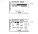
前記3Dグラフ式データエリア22cには、前記[MENU](メニュー)キーの操作に従い表示される動作メニュー(図示せず)から3Dグラフ(図形)を描画するためのアイコン[3D−Graph]を選択して表示出力部12に表示される3Dグラフ式入力画面Gf(図5参照:ここでは平面図形描画用の3Dグラフ式入力画面Gf)において、ユーザ操作に応じて入力されたグラフ式とそのパラメータのデータが記憶され、更に、後述(図6参照)の線(Line)/面(Area)選択画面Gsと描画色選択画面Gcに従い選択された前記グラフ式に応じた3Dグラフ(図形)の描画色(線色と面色)のデータが記憶されて設定される。なお、前記3Dグラフ式入力画面Gfに従い入力されるグラフ式は、予め設定された複数のグラフ式の中からユーザ操作に応じて指定されたグラフ式が入力されるものでもよい。
In the 3D graph type data area 22c, an icon [3D-Graph] for drawing a 3D graph (figure) is selected from the operation menu (not shown) displayed according to the operation of the [MENU] key. Then, on the 3D graph type input screen Gf (see FIG. 5: here, the 3D graph type input screen Gf for drawing a plane figure) displayed on the
なお、図5(A)(B)(C)に示す3Dグラフ式入力画面Gfでの平面図形描画用の各グラフ式は、その数学的表現が3元の方程式とベクトル式と行列とで異なるが、何れも同一の平面図形を描画するための数式であり、これらの数式を3Dグラフ描画において数学的に同等の数式であると定義する。 The mathematical expressions of each graph expression for drawing a plane figure on the 3D graph expression input screen Gf shown in FIGS. 5 (A), (B), and (C) are different between the ternary equation, the vector expression, and the matrix. However, all of them are mathematical formulas for drawing the same plane figure, and these mathematical formulas are defined as mathematically equivalent mathematical formulas in 3D graph drawing.
前記3Dグラフ描画データエリア22dには、前記3Dグラフ式データエリア22cに記憶された3Dグラフ(図形)のグラフ式とそのパラメータのデータ及び当該3Dグラフ(図形)の描画色(線色と面色(塗りつぶしの色または色柄))のデータに基づいて、3Dグラフ(図形)の描画データ(図形の面をグリッド(多角形)の集合で構成する各グリッドの頂点座標)と当該各グリッドに対する描画色(隣接するグリッドを画定する境界の線色とグリッド内の面色)のデータが記憶される。
In the 3D graph drawing
前記表示データエリア22eは、前記表示出力部12を構成する液晶表示ユニットの表示サイズに対応したメモリエリアを有し、このメモリエリアには、前記液晶表示ユニットに表示させるべき表示データがビットマップデータ(ここでは前記3D空間Adを表すデータと3Dグラフ(図形)の描画データ及び描画色(線色と面色)のデータとに応じて展開したカラーのビットマップデータ)として記憶される。
The
図3は、前記図形描画装置10の3Dグラフ(図形)描画機能により描画された3Dグラフ(図形)の表示状態を示す図であり、同図(A)は1つの3Dグラフ(平面図形FP)を描画した3Dグラフ画面Gdの表示状態を示す図、同図(B)は3つの3Dグラフ(平面図形FPx,FPy,FPz)を描画した3Dグラフ画面Gdの表示状態を示す図である。
FIG. 3 is a diagram showing a display state of a 3D graph (graphic) drawn by the 3D graph (graphic) drawing function of the
前記図3(A)に示す1つの3Dグラフ(平面図形FP)の場合、そのグラフ式は、
aX+bY+cZ+d=0(a=1,b=1,c=1,d=0)
であり、当該平面図形FPの平面を構成する各グリッド(多角形)の領域(単位描画領域)の描画パターン(ここでは描画色)は青色Bに設定されている。
In the case of one 3D graph (planar figure FP) shown in FIG. 3A, the graph formula is
aX + bY + cZ + d = 0 (a = 1, b = 1, c = 1, d = 0)
The drawing pattern (drawing color here) of the area (unit drawing area) of each grid (polygon) constituting the plane of the plane figure FP is set to blue B.
前記図3(B)に示す3つの3Dグラフ(平面図形FPx,FPy,FPz)の場合、そのグラフ式は、
FPx;X=0
FPy;Y=0
FPz;Z=0
であり、そのうち平面図形FPxの平面を構成する各グリッド(多角形)の領域(単位描画領域)の描画パターン(ここでは描画色)は赤色Rに、平面図形FPyの平面を構成する各グリッドの領域の描画パターンは緑色Gに、平面図形FPzの平面を構成する各グリッドの領域の描画パターンは青色Bに設定されている。
In the case of the three 3D graphs (planar figures FPx, FPy, FPz) shown in FIG. 3B, the graph formula is
FPx; X = 0
FPy; Y = 0
FPz; Z = 0
The drawing pattern (drawing color in this case) of the area (unit drawing area) of each grid (polygon) constituting the plane of the plane figure FPx is red R, and the drawing pattern (drawing color in this case) of each grid constituting the plane of the plane figure FPy is red R. The drawing pattern of the area is set to green G, and the drawing pattern of the area of each grid constituting the plane of the plane figure FPz is set to blue B.
このように、前記3Dグラフ画面Gdに表示される3Dグラフ(平面図形FPx,FPy,FPz)は、各平面図形FPx,FPy,FPzに設定された描画パターン(赤色R,緑色G,青色B)により当該各平面図形FPx,FPy,FPzを構成するグリッドの領域が描画されて表示される。 In this way, the 3D graph (plane figures FPx, FPy, FPz) displayed on the 3D graph screen Gd has drawing patterns (red R, green G, blue B) set in each plane figure FPx, FPy, FPz. The grid area constituting each of the plane figures FPx, FPy, and FPz is drawn and displayed.
このように構成された図形描画装置10(10F/10T)は、前記CPU21が前記3Dグラフ表示制御プログラム22aに記述された命令に従い回路各部の動作を制御し、ソフトウエアとハードウエアとが協働して動作することにより、後述の動作説明で述べるような3Dグラフ(図形)描画機能を実現する。
In the graphic drawing device 10 (10F / 10T) configured in this way, the CPU 21 controls the operation of each part of the circuit according to the instruction described in the 3D graph
次に、前記構成による図形描画装置10の動作について説明する。
Next, the operation of the
図4は、前記図形描画装置10の3Dグラフ描画処理を示すフローチャートである。
FIG. 4 is a flowchart showing a 3D graph drawing process of the
(第1実施形態)
図5は、前記図形描画装置10の3Dグラフ描画処理に従い3つの同じ3Dグラフ(平面図形FP1,FP2,FP3)を異なる形態の数式に基づき描画する場合の3Dグラフ式入力画面Gfを示す図である。
(First Embodiment)
FIG. 5 is a diagram showing a 3D graph type input screen Gf when three same 3D graphs (planar figures FP1, FP2, FP3) are drawn based on mathematical expressions of different forms according to the 3D graph drawing process of the
図6は、前記図形描画装置10の3Dグラフ描画処理に従い描画対象の3Dグラフ(図形)に対する描画色(描画パターン)を設定するための線(Line)/面(Area)選択画面Gs及び描画色選択画面Gcを示す図である。前記描画色選択画面Gcにより選択可能な線色と面色の描画色には透過色(Clear)が含まれる。
FIG. 6 shows a line / area selection screen Gs and a drawing color for setting a drawing color (drawing pattern) for a 3D graph (graphic) to be drawn according to the 3D graph drawing process of the
図7は、前記図形描画装置10の3Dグラフ描画処理に従い異なる描画色を設定した3つの同じ3Dグラフ(平面図形FP1,FP2,FP3)を任意に組み合わせて同時描画した場合の3Dグラフ画面Gdを示す図である。
FIG. 7 shows a 3D graph screen Gd when three same 3D graphs (planar figures FP1, FP2, FP3) in which different drawing colors are set according to the 3D graph drawing process of the
3つの同じ3Dグラフ(平面図形FP1,FP2,FP3)を描画するグラフ式(及びそのパラメータ)として、例えば、平面図形FP1のグラフ式を、図5(A)に示すように、3元の方程式により入力し、平面図形FP2のグラフ式を、図5(B)に示すように、3元のベクトル式により入力し、平面図形FP3のグラフ式を、図5(C)に示すように、3元の行列により入力する。 As a graph formula (and its parameters) for drawing three same 3D graphs (plane figures FP1, FP2, FP3), for example, the graph formula of the plane figure FP1 is a ternary equation as shown in FIG. 5 (A). The graph equation of the plane figure FP2 is input by the ternary vector equation as shown in FIG. 5 (B), and the graph equation of the plane figure FP3 is input by 3 as shown in FIG. 5 (C). Enter by the original matrix.
また、図6(A)(B)に示すような線(Line)/面(Area)選択画面Gs及び描画色選択画面Gcに従い、前記平面図形FP1の描画色(線色と面色)を青色Bに設定し、前記平面図形FP2の描画色(線色と面色)を赤色Rに設定し、前記平面図形FP3の描画色(線色と面色)を緑色Gに設定する。 Further, according to the line / area selection screen Gs and the drawing color selection screen Gc as shown in FIGS. 6A and 6B, the drawing color (line color and surface color) of the plane figure FP1 is blue B. Is set to, the drawing color (line color and surface color) of the plane figure FP2 is set to red R, and the drawing color (line color and surface color) of the plane figure FP3 is set to green G.
前記入力された各3Dグラフ(平面図形FP1,FP2,FP3)のグラフ式及びそのパラメータのデータと、前記設定された各3Dグラフ(平面図形FP1,FP2,FP3)に対する描画色のデータとは、前記3Dグラフ式データエリア22cに記憶される(ステップS1)。 The data of the graph formula and its parameters of each of the input 3D graphs (plane figures FP1, FP2, FP3) and the drawing color data for each of the set 3D graphs (plane figures FP1, FP2, FP3) are It is stored in the 3D graph type data area 22c (step S1).
そして、[EXE]キーの操作により3Dグラフ(図形)の描画の実行が指示されると(ステップS2(Yes))、前記3Dグラフ式データエリア22cに記憶されているグラフ式のデータが複数存在するか否かにより、同時の描画を必要とする複数の3Dグラフ(図形)が有るか否かが判断される(ステップS3)。 Then, when the execution of drawing the 3D graph (graphic) is instructed by operating the [EXE] key (step S2 (Yes)), there are a plurality of graph-type data stored in the 3D graph-type data area 22c. Whether or not there are a plurality of 3D graphs (graphics) that require simultaneous drawing is determined (step S3).
前記3Dグラフ式データエリア22cに前記3つの同じ3Dグラフ(平面図形FP1,FP2,FP3)のグラフ式が存在することにより、同時の描画を必要とする複数の3Dグラフ(図形)が有ると判断されると(ステップS3(Yes))、当該3つのグラフ式は数学的に同等であるか否か判断される(ステップS4)。 It is determined that there are a plurality of 3D graphs (figures) that require simultaneous drawing because the graph formulas of the three same 3D graphs (planar figures FP1, FP2, FP3) exist in the 3D graph type data area 22c. Then (step S3 (Yes)), it is determined whether or not the three graph equations are mathematically equivalent (step S4).
ここで、複数のグラフ式が数学的に同等であるとは、当該各グラフ式をそのグラフ(図形)描画処理の過程において変形したり変換したりした場合に、各グラフ式が同一の式になる場合、および、各グラフ式が同一でなくても、当該各グラフ式に対応する3Dグラフ(図形)を描画した場合、その各3Dグラフ(図形)の領域の前記3次元座標系における位置が同一となり重なって描画されることを意味する。ここで、グラフ関数電卓10Fやタブレット端末10Tに搭載されているコンピュータの演算精度によって、各グラフ式が同一でない場合でも、前記3次元座標系において、当該各グラフ式に対応する3Dグラフを描画するための複数のポリゴンの頂点座標が互いに同一になる場合がある。
Here, the fact that a plurality of graph formulas are mathematically equivalent means that each graph formula becomes the same formula when the graph formulas are transformed or converted in the process of drawing the graph (figure). When, and when a 3D graph (figure) corresponding to each graph formula is drawn even if each graph formula is not the same, the position of the region of each 3D graph (figure) in the three-dimensional coordinate system is It means that they are the same and are drawn overlapping. Here, depending on the calculation accuracy of the computer mounted on the graph
そして、前記3Dグラフ式データエリア22cに記憶された3つの3Dグラフ(平面図形FP1,FP2,FP3)のグラフ式が数学的に同等であると判断されると(ステップS4(Yes))、この後に実行する各グラフ式(図形)に対応する3Dグラフ(図形)の描画処理において、当該各3Dグラフ(図形)が相互に重なる面の各グリッドの領域の描画色(線色と面色)を、前記各グラフ式(図形)に対応して記憶されている描画色(ここでは青色B,赤色R,緑色G)の中からランダムに決定するように設定する(ステップS5)。 Then, when it is determined that the graph formulas of the three 3D graphs (plane figures FP1, FP2, FP3) stored in the 3D graph formula data area 22c are mathematically equivalent (step S4 (Yes)), this In the drawing process of the 3D graph (figure) corresponding to each graph expression (figure) to be executed later, the drawing color (line color and face color) of each grid area of the surface on which the threeD graphs (figure) overlap each other is set. It is set to be randomly determined from the drawing colors (here, blue B, red R, green G) stored corresponding to each of the graph formulas (graphics) (step S5).
すると、前記3Dグラフ式データエリア22cから読み出された3つのグラフ式にそれぞれ対応する3Dグラフ(平面図形FP1,FP2,FP3)が、前述の3Dグラフ描画処理に従い描画され、図7(E)に示すように、当該3つの平面図形FP1〜FP3が重なった平面図形FP123の3Dグラフ画面Gdとして表示出力部12に表示される。この際、前記ステップS5におけるグリッドの描画色の設定処理に従い、前記各平面図形FP1,FP2,FP3の相互に重なる面の各グリッドの領域の塗りつぶしの描画色が前記青色B,赤色R,緑色Gの中からランダムに決定されて描画される(ステップS6)。
Then, the 3D graphs (planar figures FP1, FP2, FP3) corresponding to the three graphs read from the 3D graph type data area 22c are drawn according to the above-mentioned 3D graph drawing process, and FIG. 7 (E) is shown. As shown in the above, the three plane figures FP1 to FP3 are displayed on the
すなわち、図5(A)〜(C)に示すように入力された3つの3Dグラフ式が、何れも同じ3Dグラフ(平面図形FP1,FP2,FP3)として描画される数学的に同等な数式であって、そのうち平面図形FP1のグラフ式には青色Bの描画色が設定され、平面図形FP2のグラフ式には赤色Rの描画色が設定され、平面図形FP3のグラフ式には緑色Gの描画色が設定された場合に、個々の平面図形FP1,FP2,FP3を単独で描画すると、それぞれ図7(A)(B)(C)に示すように、青色Bの平面図形FP1、赤色Rの平面図形FP2、緑色Gの平面図形FP3となって表示される。 That is, the three 3D graph formulas input as shown in FIGS. 5 (A) to 5 (C) are all mathematically equivalent formulas drawn as the same 3D graph (plane figures FP1, FP2, FP3). Among them, the drawing color of blue B is set in the graph formula of the plane figure FP1, the drawing color of red R is set in the graph formula of the plane figure FP2, and the drawing color of green G is set in the graph formula of the plane figure FP3. When the individual plane figures FP1, FP2, and FP3 are drawn independently when the color is set, as shown in FIGS. It is displayed as a plane figure FP2 and a plane figure FP3 of green G.
ここで、前記平面図形FP1のグラフ式と平面図形FP2のグラフ式とが入力されて図形の描画が実行された場合は、図7(D)に示すように、その各々に設定されている描画色(青色Bと赤色R)がグリッド毎にランダムに配色された平面図形FP12が描画されて表示され、また、前記平面図形FP2のグラフ式と平面図形FP3のグラフ式とが入力されて図形の描画が実行された場合は、図7(F)に示すように、その各々に設定されている描画色(赤色Rと緑色G)がグリッド毎にランダムに配色された平面図形FP23が描画されて表示される。 Here, when the graph formula of the plane figure FP1 and the graph formula of the plane figure FP2 are input and the drawing of the figure is executed, as shown in FIG. 7D, the drawing set for each of them is set. A plane figure FP12 in which colors (blue B and red R) are randomly arranged for each grid is drawn and displayed, and a graph formula of the plane figure FP2 and a graph formula of the plane figure FP3 are input to form a figure. When drawing is executed, as shown in FIG. 7 (F), a plane figure FP23 in which drawing colors (red R and green G) set for each of them are randomly arranged for each grid is drawn. Is displayed.
そして、前記前述したように、3つの平面図形FP1〜FP3の各グラフ式が入力されて図形の描画が実行された場合は、図7(E)に示すように、その各々に設定されている描画色(青色Bと赤色Rと緑色G)がグリッド毎にランダムに配色された平面図形FP123が描画されて表示される。 Then, as described above, when the graph expressions of the three plane figures FP1 to FP3 are input and the drawing of the figure is executed, they are set in each of them as shown in FIG. 7 (E). A plane figure FP123 in which drawing colors (blue B, red R, and green G) are randomly arranged for each grid is drawn and displayed.
これにより、前記複数の3Dグラフを描画するために入力された各数式とそのパラメータが同一である場合や、入力された各数式の表現が異なっているものの数学的には同等である場合、または、前記複数の3Dグラフの一部或いは全部の領域の前記3次元座標系内での位置が互いに略同一である場合には、複数の3Dグラフに関連付けられた複数の描画パターンのそれぞれを、前記略同一の領域に対応する複数の後述する単位描画領域の何れかに割り当て、前記複数の単位描画領域を、各単位描画領域に割り当てた描画パターンを使って描画する。これにより、この略同一の領域において、複数の3Dグラフが重なっていることを容易に知ることができる。 As a result, when each formula entered for drawing the plurality of 3D graphs and its parameters are the same, or when the expressions of the entered formulas are different but mathematically equivalent, or When the positions of a part or all the regions of the plurality of 3D graphs in the three-dimensional coordinate system are substantially the same as each other, each of the plurality of drawing patterns associated with the plurality of 3D graphs is described. Allocate to any of a plurality of unit drawing areas described later corresponding to substantially the same area, and the plurality of unit drawing areas are drawn using the drawing pattern assigned to each unit drawing area. As a result, it is possible to easily know that a plurality of 3D graphs overlap in this substantially the same region.
(第2実施形態)
図8は、前記図形描画装置10の3Dグラフ描画処理に従い3つの同じ3Dグラフ(球図形FB1,FB2,FB3)を異なる形態の数式に基づき描画する場合の3Dグラフ式入力画面Gfを示す図である。
(Second Embodiment)
FIG. 8 is a diagram showing a 3D graph type input screen Gf when three same 3D graphs (sphere figures FB1, FB2, FB3) are drawn based on mathematical formulas of different forms according to the 3D graph drawing process of the
図9は、前記図形描画装置10の3Dグラフ描画処理に従い異なる描画色を設定した3つの同じ3Dグラフ(球図形FB1,FB2,FB3)を任意に組み合わせて同時描画した場合の3Dグラフ画面Gdを示す図である。
FIG. 9 shows a 3D graph screen Gd when three same 3D graphs (spherical figures FB1, FB2, FB3) in which different drawing colors are set according to the 3D graph drawing process of the
すなわち、図8(A)(B)に示すように入力された異なる形態の3Dグラフ式が、何れも同じ3つの3Dグラフ(球図形FB1,FB2,FB3)として描画される数学的に同等な数式であって、そのうち球図形FB1のグラフ式には青色Bの描画色が設定され、球図形FB2のグラフ式には赤色Rの描画色が設定され、球図形FB3のグラフ式には緑色Gの描画色が設定された場合に、個々の球図形FB1,FB2,FB3を単独で描画すると、それぞれ図8(A)(B)(C)に示すように、青色Bの球図形FB1、赤色Rの球図形FB2、緑色Gの球図形FB3となって表示される。 That is, the 3D graph formulas of different forms input as shown in FIGS. 8 (A) and 8 (B) are all mathematically equivalent to be drawn as the same three 3D graphs (spherical figures FB1, FB2, FB3). Among the mathematical formulas, the drawing color of blue B is set in the graph formula of the spherical figure FB1, the drawing color of red R is set in the graph formula of the spherical figure FB2, and the drawing color of green G is set in the graph formula of the spherical figure FB3. When the individual sphere figures FB1, FB2, and FB3 are drawn independently when the drawing color of is set, the sphere figures FB1 and red of blue B are drawn as shown in FIGS. 8A, 8B, and 8C, respectively. It is displayed as a spherical figure FB2 of R and a spherical figure FB3 of green G.
ここで、前記球図形FB1のグラフ式と球図形FB2のグラフ式とが入力されて図形の描画が実行された場合は、図8(D)に示すように、その各々に設定されている描画色(青色Bと赤色R)がグリッド毎にランダムに配色された球図形FB12が描画されて表示され、また、前記球図形FB2のグラフ式と球図形FB3のグラフ式とが入力されて図形の描画が実行された場合は、図8(F)に示すように、その各々に設定されている描画色(赤色Rと緑色G)がグリッド毎にランダムに配色された球図形FB23が描画されて表示される。 Here, when the graph formula of the sphere figure FB1 and the graph formula of the sphere figure FB2 are input and the drawing of the figure is executed, as shown in FIG. 8D, the drawing set for each of them is set. A spherical figure FB12 in which colors (blue B and red R) are randomly arranged for each grid is drawn and displayed, and a graph expression of the spherical figure FB2 and a graph expression of the spherical figure FB3 are input to form a graphic. When drawing is executed, as shown in FIG. 8 (F), a spherical figure FB23 in which the drawing colors (red R and green G) set for each of them are randomly arranged for each grid is drawn. Is displayed.
そして、3つの球図形FB1〜FB3の各グラフ式が入力されて図形の描画が実行された場合は、図8(E)に示すように、その各々に設定されている描画色(青色Bと赤色Rと緑色G)がグリッド毎にランダムに配色された球図形FB123が描画されて表示される。 Then, when each graph formula of the three sphere figures FB1 to FB3 is input and the drawing of the figure is executed, as shown in FIG. 8 (E), the drawing colors (blue B and blue B) set for each of them are set. A spherical figure FB123 in which red R and green G) are randomly arranged for each grid is drawn and displayed.
これにより、前記複数の3Dグラフを描画するために入力された各数式とそのパラメータが同一である場合や、入力された各数式の表現が異なっているものの数学的には同等である場合、または、前記複数の3Dグラフの一部或いは全部の領域の前記3次元座標系内での位置が互いに略同一である場合には、複数の3Dグラフに関連付けられた複数の描画パターンのそれぞれを、前記略同一の領域に対応する複数の後述する単位描画領域の何れかに割り当て、前記複数の単位描画領域を、各単位描画領域に割り当てた描画パターンを使って描画する。これにより、この略同一の領域において、複数の3Dグラフが重なっていることを容易に知ることができる。 As a result, when each formula entered for drawing the plurality of 3D graphs and its parameters are the same, or when the expressions of the entered formulas are different but mathematically equivalent, or When the positions of a part or all the regions of the plurality of 3D graphs in the three-dimensional coordinate system are substantially the same as each other, each of the plurality of drawing patterns associated with the plurality of 3D graphs is described. Allocate to any of a plurality of unit drawing areas described later corresponding to substantially the same area, and the plurality of unit drawing areas are drawn using the drawing pattern assigned to each unit drawing area. As a result, it is possible to easily know that a plurality of 3D graphs overlap in this substantially the same region.
なお、前記各実施形態では、複数の3Dグラフ(図形)それぞれの面を構成する単位描画領域(グリッド)の描画パターンについて、相互に重なる単位描画領域の描画パターンを、前記各グラフ式に対応して設定された描画パターンの中からランダムに決定する構成としたが、規則正しく変化して決定する構成としてもよい。 In each of the above-described embodiments, with respect to the drawing patterns of the unit drawing areas (grids) constituting the surfaces of the plurality of 3D graphs (graphics), the drawing patterns of the unit drawing areas that overlap each other correspond to the above-mentioned graph expressions. Although the configuration is randomly determined from the drawing patterns set in the above, it may be configured to be regularly changed and determined.
また、前記3Dグラフ(図形)の面を構成する単位描画領域(グリッド)の描画パターンのうち、相互に重なる単位描画領域の隣接する領域との境界となる線(Line)の描画パターン(色)については、前記各グラフ式に対応して設定された描画パターン(色)の中からランダム又は規則正しく変化するよう決定してもよいし、各描画パターン(色)の混色、あるいは表示ドット毎に異ならせた千鳥パターンとして決定してもよい。 Further, among the drawing patterns of the unit drawing areas (grids) constituting the surface of the 3D graph (figure), the drawing patterns (colors) of the lines that are the boundaries with the adjacent areas of the unit drawing areas that overlap each other. May be determined to change randomly or regularly from the drawing patterns (colors) set corresponding to the graph formulas, or if the drawing patterns (colors) are mixed or different for each display dot. It may be determined as a staggered pattern.
さらに、前記各実施形態では、描画対象となる3Dグラフ(図形)の種類について、平面図形、球図形、円柱図形の実施形態について説明したが、他の種類の3Dグラフ(図形)についても同様に描画処理することで、図形描画装置10の表示出力部12の画面に設定される3次元座標系に複数の面を描画したときに、複数の面の少なくとも一部の領域が重なっていることを分かり易く表示することが可能である。
Further, in each of the above-described embodiments, the types of 3D graphs (graphics) to be drawn have been described with respect to the embodiments of plane figures, spherical figures, and columnar figures, but the same applies to other types of 3D graphs (graphics). By drawing, when a plurality of faces are drawn on the three-dimensional coordinate system set on the screen of the
なお、前記各実施形態において記載した図形描画装置10による各処理の手法、すなわち、図4のフローチャートに示す3Dグラフ描画処理に含まれる各手法は、何れもコンピュータに実行させることができるプログラムとして、メモリカード(ROMカード、RAMカード等)、磁気ディスク(フロッピ(登録商標)ディスク、ハードディスク等)、光ディスク(CD−ROM、DVD等)、半導体メモリ等の外部記録装置の媒体に格納して配布することができる。そして、表示機能を備えた電子機器のコンピュータ(CPU)は、この外部記録装置の媒体に記録されたプログラムを記憶装置に読み込み、この読み込んだプログラムによって動作が制御されることにより、前記各実施形態において説明した3Dグラフ(図形)描画機能を実現し、前述した手法による同様の処理を実行することができる。
The method of each process by the
また、前記各手法を実現するためのプログラムのデータは、プログラムコードの形態として通信ネットワーク(N)上を伝送させることができ、この通信ネットワーク(N)に接続されたコンピュータ装置(プログラムサーバ)から前記プログラムのデータを、表示機能を備えた電子機器に取り込んで記憶装置に記憶させ、前述した3Dグラフ(図形)描画機能を実現することもできる。 Further, the data of the program for realizing each of the above methods can be transmitted on the communication network (N) in the form of a program code, and is transmitted from a computer device (program server) connected to the communication network (N). It is also possible to take the data of the program into an electronic device having a display function and store it in a storage device to realize the above-mentioned 3D graph (graphic) drawing function.
本願発明は、前記各実施形態に限定されるものではなく、実施段階ではその要旨を逸脱しない範囲で種々に変形することが可能である。さらに、前記各実施形態には種々の段階の発明が含まれており、開示される複数の構成要件における適宜な組み合わせにより種々の発明が抽出され得る。例えば、各実施形態に示される全構成要件から幾つかの構成要件が削除されたり、幾つかの構成要件が異なる形態にして組み合わされても、発明が解決しようとする課題の欄で述べた課題が解決でき、発明の効果の欄で述べられている効果が得られる場合には、この構成要件が削除されたり組み合わされた構成が発明として抽出され得るものである。 The present invention is not limited to each of the above-described embodiments, and can be variously modified at the implementation stage without departing from the gist thereof. Further, each of the above-described embodiments includes inventions at various stages, and various inventions can be extracted by an appropriate combination of a plurality of disclosed constituent requirements. For example, even if some constituent requirements are deleted from all the constituent requirements shown in each embodiment or some constituent requirements are combined in different forms, the problems described in the section of the problem to be solved by the invention Can be solved and the effects described in the section on the effects of the invention can be obtained, the configuration in which this constituent requirement is deleted or combined can be extracted as the invention.
以下に、本願出願の当初の特許請求の範囲に記載された発明を付記する。 The inventions described in the claims of the original application of the present application are described below.
[請求項1]
表示装置の画面に設定される3次元座標系に複数の面の各々に対応する複数の単位描画領域を描画する場合であって、且つ、前記複数の面の少なくとも一部の領域の前記3次元座標系内での位置が互いに略同一であった場合、前記複数の面に関連付けられた複数の描画パターンのそれぞれを、前記複数の単位描画領域のうちの前記略同一の領域に対応する2以上の単位描画領域の何れかに割り当て、前記2以上の単位描画領域を、各単位描画領域に割り当てた描画パターンを使って描画する、
ことを特徴とする描画方法。
[Claim 1]
This is a case where a plurality of unit drawing areas corresponding to each of the plurality of faces are drawn on the three-dimensional coordinate system set on the screen of the display device, and the three dimensions of at least a part of the plurality of faces are drawn. When the positions in the coordinate system are substantially the same as each other, each of the plurality of drawing patterns associated with the plurality of surfaces is set to two or more corresponding to the substantially same area of the plurality of unit drawing areas. Allocate to any of the unit drawing areas of, and draw the two or more unit drawing areas using the drawing pattern assigned to each unit drawing area.
A drawing method characterized by that.
[請求項2]
前記複数の面を特定する複数の数式の入力を受け付け、
前記複数の数式が互いに数学的に同等であった場合、前記複数の数式の何れかにより特定される面に対応する前記複数の単位描画領域を生成する、
ことを特徴とする請求項1に記載の描画方法。
[Claim 2]
Accepts the input of multiple mathematical formulas that identify the multiple faces,
When the plurality of mathematical formulas are mathematically equivalent to each other, the plurality of unit drawing areas corresponding to the surface specified by any of the plurality of mathematical formulas are generated.
The drawing method according to
[請求項3]
前記複数の面を特定する複数の数式の入力を受け付け、
前記複数の数式により特定される前記複数の面の一部或いは全部の領域の前記3次元座標系内での位置が互いに略同一であった場合、前記略同一の領域に対応する前記複数の単位描画領域を生成する、
ことを特徴とする請求項1に記載の描画方法。
[Claim 3]
Accepts the input of multiple mathematical formulas that identify the multiple faces,
When the positions of a part or all of the plurality of surfaces specified by the plurality of mathematical expressions in the three-dimensional coordinate system are substantially the same, the plurality of units corresponding to the substantially the same region. Generate a drawing area,
The drawing method according to
[請求項4]
前記複数の面を特定する複数の数式の入力を受け付け、
前記複数の面に関連付けられた前記複数の描画パターンの設定を、前記数式毎に受け付ける、
ことを特徴とする請求項1に記載の描画方法。
[Claim 4]
Accepts the input of multiple mathematical formulas that identify the multiple faces,
The setting of the plurality of drawing patterns associated with the plurality of surfaces is accepted for each of the mathematical expressions.
The drawing method according to
[請求項5]
前記複数の数式は互いに数学的に同等であり、且つ、互いに同一の又は異なる数式表現により前記複数の数式の入力を受け付ける、
ことを特徴とする請求項2乃至請求項4の何れか1項に記載の描画方法。
[Claim 5]
The plurality of mathematical formulas are mathematically equivalent to each other, and input of the plurality of mathematical formulas is accepted by the same or different mathematical expression expressions.
The drawing method according to any one of
[請求項6]
前記複数の単位描画領域として、それぞれが多角形である複数の平面を生成する、
ことを特徴とする請求項1乃至請求項5の何れか1項に記載の描画方法。
[Claim 6]
As the plurality of unit drawing areas, a plurality of planes, each of which is a polygon, are generated.
The drawing method according to any one of
[請求項7]
前記複数の描画パターンは、前記単位描画領域の塗りつぶしの色または色柄により指定され、
前記略同一の領域内において、互いに異なる描画パターンを割り当てた2以上の単位描画領域がランダムに又は規則正しく配されるように、前記2以上の単位描画領域に対する描画パターンの割り当てを行う、
ことを特徴とする請求項1乃至請求項6の何れか1項に記載の描画方法。
[Claim 7]
The plurality of drawing patterns are designated by the fill color or color pattern of the unit drawing area.
Drawing patterns are assigned to the two or more unit drawing areas so that two or more unit drawing areas to which different drawing patterns are assigned are randomly or regularly arranged in the substantially same area.
The drawing method according to any one of
[請求項8]
前記複数の描画パターンは、前記単位描画領域を画定する線の色により指定され、
隣接する2つの単位描画領域に対して指定された2つの線の色のうちの何れか一方の色あるいはそれらの混色を、当該隣接する単位描画領域の境界を画定する線に対して指定するか、または、前記2つの線の色の表示ドットが交互に配された千鳥パターンを当該隣接する単位描画領域の境界を画定する線に対して指定する、
ことを特徴とする請求項1乃至請求項7の何れか1項に記載の描画方法。
[Claim 8]
The plurality of drawing patterns are designated by the color of the line defining the unit drawing area.
Whether to specify one of the colors of the two lines specified for the two adjacent unit drawing areas or a mixture thereof for the line defining the boundary of the adjacent unit drawing areas. Or, a staggered pattern in which the display dots of the colors of the two lines are alternately arranged is specified for the line defining the boundary of the adjacent unit drawing area.
The drawing method according to any one of
[請求項9]
表示装置の画面に設定される3次元座標系に複数の面の各々に対応する複数の単位描画領域を描画する場合であって、且つ、前記複数の面の少なくとも一部の領域の前記3次元座標系内での位置が互いに略同一であった場合、前記複数の面に関連付けられた複数の描画パターンのそれぞれを、前記複数の単位描画領域のうちの前記略同一の領域に対応する2以上の単位描画領域の何れかに割り当て、前記2以上の単位描画領域を、各単位描画領域に割り当てた描画パターンを使って描画する、描画制御部
を備えることを特徴とする描画装置。
[Claim 9]
This is a case where a plurality of unit drawing areas corresponding to each of the plurality of faces are drawn on the three-dimensional coordinate system set on the screen of the display device, and the three dimensions of at least a part of the plurality of faces are drawn. When the positions in the coordinate system are substantially the same as each other, each of the plurality of drawing patterns associated with the plurality of surfaces is set to two or more corresponding to the substantially same area of the plurality of unit drawing areas. A drawing device comprising a drawing control unit that is assigned to any of the unit drawing areas of the above and draws the two or more unit drawing areas by using the drawing pattern assigned to each unit drawing area.
[請求項10]
コンピュータを、
表示装置の画面に設定される3次元座標系に複数の面の各々に対応する複数の単位描画領域を描画する場合であって、且つ、前記複数の面の少なくとも一部の領域の前記3次元座標系内での位置が互いに略同一であった場合、前記複数の面に関連付けられた複数の描画パターンのそれぞれを、前記複数の単位描画領域のうちの前記略同一の領域に対応する2以上の単位描画領域の何れかに割り当て、前記2以上の単位描画領域を、各単位描画領域に割り当てた描画パターンを使って描画する、描画手段、
として機能させるためのコンピュータ読み込み可能なプログラム。
[Claim 10]
Computer,
This is a case where a plurality of unit drawing areas corresponding to each of the plurality of faces are drawn on the three-dimensional coordinate system set on the screen of the display device, and the three dimensions of at least a part of the plurality of faces are drawn. When the positions in the coordinate system are substantially the same as each other, each of the plurality of drawing patterns associated with the plurality of surfaces is set to two or more corresponding to the substantially same area of the plurality of unit drawing areas. A drawing means that allocates to any of the unit drawing areas of the above and draws the two or more unit drawing areas using the drawing pattern assigned to each unit drawing area.
A computer-readable program to function as.
10 …図形描画装置
10F…グラフ関数電卓
10T…タブレット端末
11 …キー入力部
12 …表示出力部
21 …CPU
22 …メモリ
22a…3Dグラフ表示制御プログラム
22b…V−Windowデータエリア
22c…3Dグラフ式データエリア
22d…3Dグラフ描画データエリア
22e…表示データエリア
23 …外部記録媒体
24 …記録媒体読取部
25 …通信部
30 …Webサーバ
N …通信ネットワーク
R …赤色
B …青色
G …緑色
Gf…3Dグラフ式入力画面
Gs…線(Line)/面(Area)選択画面
Gc…描画色選択画面
Gd…3Dグラフ画面
Ad…3D空間
10 ... Drawing
22 ...
Claims (8)
3次元座標系において、第1の面の少なくとも一部の領域と第2の面の少なくとも一部の領域とが互いに略同一であった場合、前記第1の面に関連付けられた第1の描画パターンと前記第2の面に関連付けられた第2の描画パターンとのそれぞれを、前記第1の面の前記少なくとも一部の領域または前記第2の面の前記少なくとも一部の領域において、前記第1の描画パターンおよび前記第2の描画パターンがランダムに又は規則正しく配されるように、前記第1の面の前記少なくとも一部の領域または前記第2の面の前記少なくとも一部の領域を形成する複数の単位描画領域の何れかに割り当てて、2以上の前記単位描画領域を、各単位描画領域に割り当てた描画パターンを使って描画することによって、前記第1の面または前記第2の面の前記少なくとも一部の領域を描画する、
描画方法。 By the control unit of the drawing device
In the three-dimensional coordinate system, when at least a part of the area of the first surface and at least a part of the area of the second surface are substantially the same as each other, the first drawing associated with the first surface is performed. Each of the pattern and the second drawing pattern associated with the second surface is, in the at least a part of the area of the first surface or at least a part of the area of the second surface. The at least a part of the first surface or the at least a part of the second surface is formed so that the drawing pattern 1 and the second drawing pattern are randomly or regularly arranged. assigned to one of a plurality of unit drawing areas, two or more of the unit drawing area, by drawing using a drawing pattern assigned to each unit drawing area, of the first surface or the second surface Draw at least a part of the area.
Drawing method.
請求項1に記載の描画方法。 Wherein each of the first drawing pattern and the second drawing pattern, Ru specified by fill color or color pattern of the unit drawing area,
The drawing method according to claim 1.
前記単位描画領域を画定する線の少なくとも一部を共有する2つの単位描画領域に対して指定された2つの線の色が異なる場合に、前記2つの線の色のうちの何れか一方の色あるいはそれらの混色を、共有された前記線の少なくとも一部に対して指定するか、または、前記2つの線の色の表示ドットが交互に配された千鳥パターンを、共有された前記線の少なくとも一部に対して指定する、
請求項1または請求項2に記載の描画方法。 Each of the first drawing pattern and the second drawing pattern is designated by the color of the line defining the unit drawing area.
When the colors of the two lines specified for the two unit drawing areas that share at least a part of the lines defining the unit drawing area are different, the color of one of the two lines is different. Alternatively, a mixture of these colors is specified for at least a part of the shared line, or a staggered pattern in which display dots of the colors of the two lines are alternately arranged is specified for at least a part of the shared line. Specify for some,
The drawing method according to claim 1 or 2.
請求項1乃至請求項3のいずれか一項に記載の描画方法。 It accepts input of the first mathematical expression that specifies the first surface and the second mathematical expression that specifies the second surface.
The drawing method according to any one of claims 1 to 3.
請求項4に記載の描画方法。 The second mathematical expression that identifies the second surface is mathematically equivalent to the first mathematical expression and is the same as or different from the expression of the first mathematical expression.
The drawing method according to claim 4.
請求項1乃至請求項5のいずれか一項に記載の描画方法。 As the plurality of unit drawing areas, a plurality of planes, each of which is a polygon, are generated.
The drawing method according to any one of claims 1 to 5.
前記制御部は、
3次元座標系において、第1の面の少なくとも一部の領域と第2の面の少なくとも一部の領域とが互いに略同一であった場合、前記第1の面に関連付けられた第1の描画パターンと前記第2の面に関連付けられた第2の描画パターンとのそれぞれを、前記第1の面の前記少なくとも一部の領域または前記第2の面の前記少なくとも一部の領域において、前記第1の描画パターンおよび前記第2の描画パターンがランダムに又は規則正しく配されるように、前記第1の面の前記少なくとも一部の領域または前記第2の面の前記少なくとも一部の領域を形成する複数の単位描画領域の何れかに割り当てて、2以上の前記単位描画領域を、各単位描画領域に割り当てた描画パターンを使って描画することによって、前記第1の面または前記第2の面の前記少なくとも一部の領域を描画する、
描画装置。 A drawing device equipped with a control unit
The control unit
In the three-dimensional coordinate system, when at least a part of the area of the first surface and at least a part of the area of the second surface are substantially the same as each other, the first drawing associated with the first surface is performed. Each of the pattern and the second drawing pattern associated with the second surface is, in the at least a part of the area of the first surface or at least a part of the area of the second surface. The at least a part of the first surface or the at least a part of the second surface is formed so that the drawing pattern 1 and the second drawing pattern are randomly or regularly arranged. assigned to one of a plurality of unit drawing areas, two or more of the unit drawing area, by drawing using a drawing pattern assigned to each unit drawing area, of the first surface or the second surface Draw at least a part of the area.
Drawing device.
3次元座標系において、第1の面の少なくとも一部の領域と第2の面の少なくとも一部の領域とが互いに略同一であった場合、前記第1の面に関連付けられた第1の描画パターンと前記第2の面に関連付けられた第2の描画パターンとのそれぞれを、前記第1の面の前記少なくとも一部の領域または前記第2の面の前記少なくとも一部の領域において、前記第1の描画パターンおよび前記第2の描画パターンがランダムに又は規則正しく配されるように、前記第1の面の前記少なくとも一部の領域または前記第2の面の前記少なくとも一部の領域を形成する複数の単位描画領域の何れかに割り当てて、2以上の前記単位描画領域を、各単位描画領域に割り当てた描画パターンを使って描画することによって、前記第1の面または前記第2の面の前記少なくとも一部の領域を描画する、
ように機能させるためのコンピュータ読み込み可能なプログラム。 Computer,
In the three-dimensional coordinate system, when at least a part of the area of the first surface and at least a part of the area of the second surface are substantially the same as each other, the first drawing associated with the first surface is performed. Each of the pattern and the second drawing pattern associated with the second surface is, in the at least a part of the area of the first surface or at least a part of the area of the second surface. The at least a part of the first surface or the at least a part of the second surface is formed so that the drawing pattern 1 and the second drawing pattern are randomly or regularly arranged. assigned to one of a plurality of unit drawing areas, two or more of the unit drawing area, by drawing using a drawing pattern assigned to each unit drawing area, of the first surface or the second surface Draw at least a part of the area.
A computer-readable program to make it work.
Priority Applications (3)
| Application Number | Priority Date | Filing Date | Title |
|---|---|---|---|
| JP2017005990A JP6965518B2 (en) | 2017-01-17 | 2017-01-17 | Drawing method, drawing device, and program |
| US15/873,326 US10818098B2 (en) | 2017-01-17 | 2018-01-17 | Drawing method for assigning drawing patterns to unit drawing area forming at least part of first surface or at least part of second surface, drawing apparatus, and recording medium |
| CN201810043099.1A CN108335358B (en) | 2017-01-17 | 2018-01-17 | Drawing method, drawing device, and recording medium |
Applications Claiming Priority (1)
| Application Number | Priority Date | Filing Date | Title |
|---|---|---|---|
| JP2017005990A JP6965518B2 (en) | 2017-01-17 | 2017-01-17 | Drawing method, drawing device, and program |
Publications (3)
| Publication Number | Publication Date |
|---|---|
| JP2018116407A JP2018116407A (en) | 2018-07-26 |
| JP2018116407A5 JP2018116407A5 (en) | 2020-01-23 |
| JP6965518B2 true JP6965518B2 (en) | 2021-11-10 |
Family
ID=62840684
Family Applications (1)
| Application Number | Title | Priority Date | Filing Date |
|---|---|---|---|
| JP2017005990A Active JP6965518B2 (en) | 2017-01-17 | 2017-01-17 | Drawing method, drawing device, and program |
Country Status (3)
| Country | Link |
|---|---|
| US (1) | US10818098B2 (en) |
| JP (1) | JP6965518B2 (en) |
| CN (1) | CN108335358B (en) |
Families Citing this family (4)
| Publication number | Priority date | Publication date | Assignee | Title |
|---|---|---|---|---|
| JP6939135B2 (en) * | 2017-06-23 | 2021-09-22 | カシオ計算機株式会社 | Electronic devices, programs, servers, graph image generation methods and graph image generation systems |
| AT521847A1 (en) * | 2018-11-09 | 2020-05-15 | Hueck Folien Gmbh | Method of making a security feature |
| KR102511495B1 (en) * | 2020-12-01 | 2023-03-17 | 서울과학기술대학교 산학협력단 | Method for generating realistic content |
| JP7243754B2 (en) * | 2021-03-24 | 2023-03-22 | カシオ計算機株式会社 | Graph display device, graph display method, and program |
Family Cites Families (9)
| Publication number | Priority date | Publication date | Assignee | Title |
|---|---|---|---|---|
| JPH05258075A (en) | 1992-03-12 | 1993-10-08 | Nec Software Kansai Ltd | Frame plotting method for three-dimensional plane for two-dimensional color display device |
| US5649078A (en) * | 1995-03-22 | 1997-07-15 | International Business Machines Corporation | Efficient two-pass rasterization scheme utilizing visibility information |
| JPH09330422A (en) | 1996-06-07 | 1997-12-22 | Hitachi Ltd | Three-dimensional graphic displaying method and system therefor |
| US5870098A (en) * | 1997-02-26 | 1999-02-09 | Evans & Sutherland Computer Corporation | Method for rendering shadows on a graphical display |
| JP4399910B2 (en) | 1998-09-10 | 2010-01-20 | 株式会社セガ | Image processing apparatus and method including blending processing |
| JP4411713B2 (en) | 1999-12-13 | 2010-02-10 | 株式会社セガ | Image processing apparatus and method including blending processing |
| US8698799B2 (en) * | 2009-01-20 | 2014-04-15 | Adobe Systems Incorporated | Method and apparatus for rendering graphics using soft occlusion |
| JP5521668B2 (en) | 2010-03-17 | 2014-06-18 | カシオ計算機株式会社 | Inequality display device and inequality display program |
| DK3005308T3 (en) * | 2013-06-06 | 2018-01-22 | Vert Rotors Uk Ltd | PROCEDURE FOR USING A COMPUTER GRAPHIC SYSTEM TO CHANGE THE FORM OF THE SURFACE OF MODELS OF GEOMETRIC SOLIDS BY DEFORMATION AND IMPLEMENTATION THEREOF |
-
2017
- 2017-01-17 JP JP2017005990A patent/JP6965518B2/en active Active
-
2018
- 2018-01-17 CN CN201810043099.1A patent/CN108335358B/en active Active
- 2018-01-17 US US15/873,326 patent/US10818098B2/en active Active
Also Published As
| Publication number | Publication date |
|---|---|
| JP2018116407A (en) | 2018-07-26 |
| CN108335358B (en) | 2023-05-02 |
| US20180204389A1 (en) | 2018-07-19 |
| US10818098B2 (en) | 2020-10-27 |
| CN108335358A (en) | 2018-07-27 |
Similar Documents
| Publication | Publication Date | Title |
|---|---|---|
| JP6965518B2 (en) | Drawing method, drawing device, and program | |
| US10460528B2 (en) | Figure drawing apparatus, control method of figure drawing apparatus, and recording medium | |
| JP6992491B2 (en) | Display device, display method, and program | |
| EP3340179B1 (en) | Figure plotting device, figure plotting method, and recording medium | |
| AU2018204594A1 (en) | Graph display method, graph generating method, electronic device, and recording medium | |
| JP2012083883A (en) | Screen data preparation device | |
| JP5786542B2 (en) | Formula input device and program | |
| JP2701056B2 (en) | Secondary representation method for three-dimensional objects | |
| JP6142553B2 (en) | Graphic display control apparatus, graphic display control method, and program | |
| JPH07114655A (en) | Graphic processor | |
| JP7206704B2 (en) | Information processing method, information processing device, and program | |
| JP5494227B2 (en) | Graphic learning apparatus and program | |
| JP2610832B2 (en) | Screen division pattern registration method | |
| JP5617961B2 (en) | Graphic display device and program | |
| JPH04358284A (en) | Plotting method by computer aided design device | |
| JPH07271842A (en) | Graphic processor | |
| JPH05334413A (en) | Mask pattern generating system | |
| JPH02205981A (en) | Display system for color mixed area | |
| JPH0935079A (en) | Image input device | |
| JPS61153775A (en) | Displaying device | |
| JPH04304556A (en) | Picture processor | |
| JPH02204875A (en) | Mask pattern changing system for airbrush process |
Legal Events
| Date | Code | Title | Description |
|---|---|---|---|
| A521 | Request for written amendment filed |
Free format text: JAPANESE INTERMEDIATE CODE: A523 Effective date: 20191204 |
|
| A621 | Written request for application examination |
Free format text: JAPANESE INTERMEDIATE CODE: A621 Effective date: 20191204 |
|
| A977 | Report on retrieval |
Free format text: JAPANESE INTERMEDIATE CODE: A971007 Effective date: 20201224 |
|
| A131 | Notification of reasons for refusal |
Free format text: JAPANESE INTERMEDIATE CODE: A131 Effective date: 20210202 |
|
| A521 | Request for written amendment filed |
Free format text: JAPANESE INTERMEDIATE CODE: A523 Effective date: 20210401 |
|
| TRDD | Decision of grant or rejection written | ||
| A01 | Written decision to grant a patent or to grant a registration (utility model) |
Free format text: JAPANESE INTERMEDIATE CODE: A01 Effective date: 20210921 |
|
| A61 | First payment of annual fees (during grant procedure) |
Free format text: JAPANESE INTERMEDIATE CODE: A61 Effective date: 20211004 |
|
| R150 | Certificate of patent or registration of utility model |
Ref document number: 6965518 Country of ref document: JP Free format text: JAPANESE INTERMEDIATE CODE: R150 |