JP6964582B2 - A method for preventing cracking in an optical fiber preform, and an optical fiber preform obtained by the above method. - Google Patents
A method for preventing cracking in an optical fiber preform, and an optical fiber preform obtained by the above method. Download PDFInfo
- Publication number
- JP6964582B2 JP6964582B2 JP2018517578A JP2018517578A JP6964582B2 JP 6964582 B2 JP6964582 B2 JP 6964582B2 JP 2018517578 A JP2018517578 A JP 2018517578A JP 2018517578 A JP2018517578 A JP 2018517578A JP 6964582 B2 JP6964582 B2 JP 6964582B2
- Authority
- JP
- Japan
- Prior art keywords
- core
- clad
- soot
- thermal expansion
- preform
- Prior art date
- Legal status (The legal status is an assumption and is not a legal conclusion. Google has not performed a legal analysis and makes no representation as to the accuracy of the status listed.)
- Active
Links
Images


Classifications
-
- C—CHEMISTRY; METALLURGY
- C03—GLASS; MINERAL OR SLAG WOOL
- C03B—MANUFACTURE, SHAPING, OR SUPPLEMENTARY PROCESSES
- C03B37/00—Manufacture or treatment of flakes, fibres, or filaments from softened glass, minerals, or slags
- C03B37/01—Manufacture of glass fibres or filaments
- C03B37/012—Manufacture of preforms for drawing fibres or filaments
- C03B37/01205—Manufacture of preforms for drawing fibres or filaments starting from tubes, rods, fibres or filaments
- C03B37/01211—Manufacture of preforms for drawing fibres or filaments starting from tubes, rods, fibres or filaments by inserting one or more rods or tubes into a tube
- C03B37/01222—Manufacture of preforms for drawing fibres or filaments starting from tubes, rods, fibres or filaments by inserting one or more rods or tubes into a tube for making preforms of multiple core optical fibres
-
- C—CHEMISTRY; METALLURGY
- C03—GLASS; MINERAL OR SLAG WOOL
- C03B—MANUFACTURE, SHAPING, OR SUPPLEMENTARY PROCESSES
- C03B37/00—Manufacture or treatment of flakes, fibres, or filaments from softened glass, minerals, or slags
- C03B37/01—Manufacture of glass fibres or filaments
- C03B37/012—Manufacture of preforms for drawing fibres or filaments
- C03B37/01205—Manufacture of preforms for drawing fibres or filaments starting from tubes, rods, fibres or filaments
- C03B37/01225—Means for changing or stabilising the shape, e.g. diameter, of tubes or rods in general, e.g. collapsing
- C03B37/01248—Means for changing or stabilising the shape, e.g. diameter, of tubes or rods in general, e.g. collapsing by collapsing without drawing
-
- C—CHEMISTRY; METALLURGY
- C03—GLASS; MINERAL OR SLAG WOOL
- C03B—MANUFACTURE, SHAPING, OR SUPPLEMENTARY PROCESSES
- C03B37/00—Manufacture or treatment of flakes, fibres, or filaments from softened glass, minerals, or slags
- C03B37/01—Manufacture of glass fibres or filaments
- C03B37/02—Manufacture of glass fibres or filaments by drawing or extruding, e.g. direct drawing of molten glass from nozzles; Cooling fins therefor
- C03B37/025—Manufacture of glass fibres or filaments by drawing or extruding, e.g. direct drawing of molten glass from nozzles; Cooling fins therefor from reheated softened tubes, rods, fibres or filaments, e.g. drawing fibres from preforms
- C03B37/027—Fibres composed of different sorts of glass, e.g. glass optical fibres
-
- C—CHEMISTRY; METALLURGY
- C03—GLASS; MINERAL OR SLAG WOOL
- C03B—MANUFACTURE, SHAPING, OR SUPPLEMENTARY PROCESSES
- C03B2201/00—Type of glass produced
- C03B2201/02—Pure silica glass, e.g. pure fused quartz
-
- C—CHEMISTRY; METALLURGY
- C03—GLASS; MINERAL OR SLAG WOOL
- C03B—MANUFACTURE, SHAPING, OR SUPPLEMENTARY PROCESSES
- C03B2201/00—Type of glass produced
- C03B2201/06—Doped silica-based glasses
-
- C—CHEMISTRY; METALLURGY
- C03—GLASS; MINERAL OR SLAG WOOL
- C03B—MANUFACTURE, SHAPING, OR SUPPLEMENTARY PROCESSES
- C03B2201/00—Type of glass produced
- C03B2201/06—Doped silica-based glasses
- C03B2201/30—Doped silica-based glasses doped with metals, e.g. Ga, Sn, Sb, Pb or Bi
- C03B2201/31—Doped silica-based glasses doped with metals, e.g. Ga, Sn, Sb, Pb or Bi doped with germanium
-
- C—CHEMISTRY; METALLURGY
- C03—GLASS; MINERAL OR SLAG WOOL
- C03B—MANUFACTURE, SHAPING, OR SUPPLEMENTARY PROCESSES
- C03B2203/00—Fibre product details, e.g. structure, shape
- C03B2203/10—Internal structure or shape details
- C03B2203/22—Radial profile of refractive index, composition or softening point
- C03B2203/224—Mismatching coefficients of thermal expansion [CTE] of glass layers
-
- C—CHEMISTRY; METALLURGY
- C03—GLASS; MINERAL OR SLAG WOOL
- C03B—MANUFACTURE, SHAPING, OR SUPPLEMENTARY PROCESSES
- C03B2203/00—Fibre product details, e.g. structure, shape
- C03B2203/10—Internal structure or shape details
- C03B2203/22—Radial profile of refractive index, composition or softening point
- C03B2203/225—Matching coefficients of thermal expansion [CTE] of glass layers
-
- C—CHEMISTRY; METALLURGY
- C03—GLASS; MINERAL OR SLAG WOOL
- C03B—MANUFACTURE, SHAPING, OR SUPPLEMENTARY PROCESSES
- C03B2203/00—Fibre product details, e.g. structure, shape
- C03B2203/10—Internal structure or shape details
- C03B2203/22—Radial profile of refractive index, composition or softening point
- C03B2203/23—Double or multiple optical cladding profiles
-
- C—CHEMISTRY; METALLURGY
- C03—GLASS; MINERAL OR SLAG WOOL
- C03B—MANUFACTURE, SHAPING, OR SUPPLEMENTARY PROCESSES
- C03B2203/00—Fibre product details, e.g. structure, shape
- C03B2203/34—Plural core other than bundles, e.g. double core
-
- Y—GENERAL TAGGING OF NEW TECHNOLOGICAL DEVELOPMENTS; GENERAL TAGGING OF CROSS-SECTIONAL TECHNOLOGIES SPANNING OVER SEVERAL SECTIONS OF THE IPC; TECHNICAL SUBJECTS COVERED BY FORMER USPC CROSS-REFERENCE ART COLLECTIONS [XRACs] AND DIGESTS
- Y02—TECHNOLOGIES OR APPLICATIONS FOR MITIGATION OR ADAPTATION AGAINST CLIMATE CHANGE
- Y02P—CLIMATE CHANGE MITIGATION TECHNOLOGIES IN THE PRODUCTION OR PROCESSING OF GOODS
- Y02P40/00—Technologies relating to the processing of minerals
- Y02P40/50—Glass production, e.g. reusing waste heat during processing or shaping
- Y02P40/57—Improving the yield, e-g- reduction of reject rates
Landscapes
- Engineering & Computer Science (AREA)
- Chemical & Material Sciences (AREA)
- Life Sciences & Earth Sciences (AREA)
- General Life Sciences & Earth Sciences (AREA)
- Geochemistry & Mineralogy (AREA)
- Manufacturing & Machinery (AREA)
- Materials Engineering (AREA)
- Organic Chemistry (AREA)
- Manufacture, Treatment Of Glass Fibers (AREA)
- Glass Compositions (AREA)
Description
本出願は、米国特許法第119条の下で、2015年10月7日出願の米国仮特許出願第62/238,370号の優先権の利益を主張するものであり、上記仮特許出願の内容は信頼できるものであり、その全体が参照により本出願に援用される。 This application claims the priority benefit of U.S. Provisional Patent Application No. 62 / 238,370 filed on October 7, 2015 under Article 119 of the U.S. Patent Act. The content is credible and the entire content is incorporated herein by reference.
本記載は、光ファイバの作製に使用されるプリフォームに関する。より詳細には、本記載は、ケーン・イン・スート(cane‐in‐soot)プロセスで作製される光ファイバプリフォームに関する。より詳細には、本記載は、コア‐クラッド比が大きい、割れのない光ファイバプリフォームに関する。 This description relates to preforms used in the fabrication of optical fibers. More specifically, this description relates to fiber optic preforms made in a cane-in-suit process. More specifically, this description relates to a crack-free fiber optic preform with a large core-clad ratio.
光通信システムは、高伝送速度及び高帯域幅を提供するため、データ伝送に関してますます重要となっている。光通信システムの成功は、データ伝送システムにおいて使用される光ファイバの品質に大きく依存する。光ファイバは、光データ信号を、高い忠実度及び低い減衰で伝送する必要がある。 Optical communication systems are becoming more and more important with respect to data transmission because they provide high transmission speeds and high bandwidth. The success of optical communication systems depends largely on the quality of the optical fibers used in data transmission systems. Optical fibers need to transmit optical data signals with high fidelity and low attenuation.
光ファイバは、プリフォームからファイバをドロー形成することによって作製される。プリフォームは、典型的にはドーパントのレベル又はタイプが異なるシリカガラスの一連の同心領域を含む、固結済みシリカガラスである。ファイバプリフォーム中のドーパントの空間分布、濃度及び/又はタイプの制御は、屈折率が異なる複数の領域を生成する。屈折率の差は、プリフォームからドロー形成されたファイバにおいて明白であり、光ファイバの異なる複数の機能領域(例えば、コア対クラッド、低屈折率窪み、調整された屈折率プロファイル)を規定する。 Optical fibers are made by drawing fibers from preforms. The preform is a consolidated silica glass that typically comprises a series of concentric regions of silica glass with different levels or types of dopants. Controlling the spatial distribution, concentration and / or type of dopant in the fiber preform produces multiple regions with different indices of refraction. The difference in index of refraction is apparent in fibers drawn from preforms and defines different functional regions of the optical fiber (eg, core vs. clad, low index of refraction recess, adjusted index of refraction profile).
光ファイバプリフォームを製造するための1つの従来の方法は、外側蒸着プロセスであり、これは、シリカ(又はドープシリカ)スートをシリカ(又はドープシリカ)ケーン(cane)上に堆積させることを必要とする。上記ケーンは、概ね円筒形の幾何学的形状を有する、完全に固結したガラスであり、ファイバプリフォームの中心部分となる。上記ケーンは、最終的にプリフォームからドロー形成されるファイバの高屈折率コア領域として望ましい組成を有する(そのため、コアケーンと呼ばれることが多い)。上記シリカスートはケーンを取り囲むことができ、また単一の組成物の単一の層又は組成が異なる一連の複数の層として堆積させることができ、上記1つ以上の層の組成は、最終的にプリフォームからドロー形成される繊維のクラッド領域に所望の屈折率プロファイルを提供するよう設計される。上記1つ以上のスートクラッド層は典型的には、ドーパントの濃度又はタイプが異なる、複数の非ドープシリカ及びドープシリカ層を含む。 One conventional method for producing fiber optic preforms is an outer vapor deposition process, which requires depositing silica (or dope silica) soot on silica (or dope silica) cane. .. The cane is a fully consolidated glass having a generally cylindrical geometry and is the central portion of the fiber preform. The cane has a desirable composition as a high refractive index core region of the fiber finally drawn from the preform (hence the name core cane). The silica soot can surround the cane and can be deposited as a single layer of a single composition or as a series of layers with different compositions, the composition of the one or more layers finally It is designed to provide the desired index of refraction profile for the clad region of the fiber drawn from the preform. The one or more soot-clad layers typically include a plurality of non-doped silica and doped silica layers of different dopant concentrations or types.
クラッドスートは通常、1つ以上の前駆材料の火炎反応によって製造される。上記火炎反応は、火炎加水分解又は火炎燃焼であってよい。火炎加水分解では、水が反応物として存在し、スート前駆材料と反応してクラッドスートを形成する。火炎燃焼では、水は反応物ではないが、副産物として生成される場合がある。シリカスートのための一般的な前駆材料としては、SiCl4及びOMCTS(オクタメチルシクロテトラシロキサン)が挙げられる。スート堆積反応中に水が存在することにより、シリカスート中、並びにケーンの表面及び表面付近領域における、OHの高い濃度がもたらされ得る。OH基の濃度を低減するために、スート堆積後に脱水ステップを実施する。上記脱水ステップでは、スート及びケーンを、OHを除去するように作用する脱水剤(例えばCl2)に曝露する。堆積されたままの状態のスートの高い多孔率は、この脱水ステップにおけるスート層からのOHの除去を促進する。しかしながら、ケーンの高密度特性は、脱水剤によるケーンへの浸透を阻害し、プリフォームのケーン部分に有意量のOHが残る場合がある。プリフォーム中のOHの存在は、プリフォームからドロー形成されたファイバ中に高濃度のOHをもたらし、また、約1350nm〜約1425mmに亘る広いOH吸収帯域により、1380nm又はその付近の光信号に関する高いファイバ減衰損失をもたらす。 Clad soots are usually produced by a flame reaction of one or more precursor materials. The flame reaction may be flame hydrolysis or flame combustion. In flame hydrolysis, water is present as a reactant and reacts with the soot precursor material to form clad soot. In flame combustion, water is not a reactant but may be produced as a by-product. Common precursors for silica soot include SiCl 4 and OMCTS (octamethylcyclotetrasiloxane). The presence of water during the soot deposition reaction can result in high concentrations of OH in the silica soot and in the surface and near-surface regions of the cane. A dehydration step is performed after soot deposition to reduce the concentration of OH groups. In the dehydration step, the suit and cane are exposed to a dehydrating agent (eg, Cl 2) that acts to remove OH. The high porosity of the soot in the as-deposited state facilitates the removal of OH from the soot layer during this dehydration step. However, the high density properties of the cane may prevent the dehydrating agent from penetrating into the cane, leaving a significant amount of OH in the cane portion of the preform. The presence of OH in the preform results in a high concentration of OH in the fiber drawn from the preform and is high for optical signals at or near 1380 nm due to the wide OH absorption band ranging from about 1350 nm to about 1425 mm. It results in fiber attenuation loss.
伝送ファイバ中の光信号は主にコア領域に閉じ込められるため、ファイバコア中のOH濃度を最小化することが特に重要であり、これはコアケーン(ファイバプリフォームの、そこからファイバコアがドロー形成される領域)中のOH濃度の最小化を必要とする。コアケーン中のOHの存在を最小化するために使用される典型的戦略は、高屈折率領域をコアケーンの中心へと局在化することである。コアケーンの高屈折率領域は典型的には、アップドープシリカ(例えばGeドープシリカ)から形成され、アップドープの領域はコアケーンの中心部分に限定される。目的は、コアケーンの外側径方向境界から十分な距離にアップドープ領域を維持して、高屈折率をOH汚染から保護することである。コアケーンの、中心のアップドープ領域と外側径方向境界との間の部分は、コアケーンの表面上に形成されるOHの拡散を阻止するためのバッファとして作用する。コアケーンは固結した状態であるため、コアケーンの表面から中心へのOHの拡散は、現実的なタイムスケールでは発生せず、OHはコアケーンの表面及び表面付近領域に局在化される。コアケーンの内部の高屈折率領域を、表面付近領域から十分な距離に位置決めすることにより、高屈折率領域内のOHの存在を最小化でき、OH吸収による減衰損失が回避される。 Since the optical signal in the transmission fiber is mainly confined in the core region, it is especially important to minimize the OH concentration in the fiber core, which is the core cane (of the fiber preform, from which the fiber core is drawn). It is necessary to minimize the OH concentration in the region. A typical strategy used to minimize the presence of OH in the core cane is to localize the high index region to the center of the core cane. The high index region of the core cane is typically formed from up-doped silica (eg, Ge-doped silica), and the up-doped region is limited to the central portion of the core cane. The purpose is to maintain the up-doped region at a sufficient distance from the outer radial boundary of the core cane to protect the high index of refraction from OH contamination. The portion of the core cane between the central up-doped region and the outer radial boundary acts as a buffer to prevent the diffusion of OH formed on the surface of the core cane. Since the core cane is in a consolidated state, diffusion of OH from the surface to the center of the core cane does not occur on a realistic time scale, and OH is localized on the surface of the core cane and the region near the surface. By positioning the high refractive index region inside the core cane at a sufficient distance from the region near the surface, the presence of OH in the high refractive index region can be minimized, and the attenuation loss due to OH absorption can be avoided.
典型的には、高屈折率領域はコアケーンの中心に存在し、高屈折率領域の径方向範囲は、コアケーンのコア‐クラッド比によって定量化できる。コア‐クラッド比は、コアケーンの外径に対する高屈折率領域の半径の比として定義される。例えば0.5のコア‐クラッド比は、コアケーンの高屈折率(アップドープ)領域の半径がコアケーンの総半径の半分であることを意味する。従来の外側蒸着プロセスでは、コア‐クラッド比を小さく(例えば<0.33に)維持することによって、プリフォームのアップドープ内、及び上記プリフォームからドロー形成されたファイバのコア中の、OHの存在を最小化する。しかしながら、コア‐クラッド比が小さいコアケーンの利用は、アップドープ領域の寸法を超えてコアケーンを拡大するために必要な時間及び材料のコストを理由として、加工の観点から非経済的である。 Typically, the high index region resides in the center of the core cane, and the radial range of the high index region can be quantified by the core-clad ratio of the core cane. The core-clad ratio is defined as the ratio of the radius of the high index region to the outer diameter of the core cane. For example, a core-clad ratio of 0.5 means that the radius of the high refractive index (updoping) region of the core cane is half the total radius of the core cane. In a conventional outer deposition process, by keeping the core-clad ratio small (eg at <0.33), the OH in the preform updope and in the core of the fiber drawn from the preform. Minimize existence. However, the use of core canes with a small core-clad ratio is uneconomical from a processing point of view because of the time and material costs required to extend the core canes beyond the dimensions of the up-doped region.
ケーン・イン・スートプロセスは、水に対するコアケーンの曝露を回避する、ファイバプリフォームを作製するための代替的な方法である。ケーン・イン・スートプロセスでは、コアケーン及びスートクラッドモノリスを別個のプロセスで形成した後、接合してコア‐クラッド組立体を形成し、これを固結させてプリフォームを形成する。スートクラッドモノリスは多孔性であり、中にコアケーンが配置される内部キャビティを含む。固結により多孔性スートクラッドモノリスを高密度化し、またコアケーンをスートクラッドモノリスに融着させて、ファイバプリフォームとして使用できる一体型の本体を形成する。コアケーン及びスートクラッドモノリスが独立して形成されるため、コアケーンは、クラッドスート堆積プロセスに存在する水反応物又は副産物に曝露されない。コアケーンは、水が存在しない環境で形成、脱水及び固結できる。同様に、スートクラッドモノリスは、多孔性の状態のまま堆積及び脱水でき、これにより、コアケーンとスートクラッドモノリスとの接合前にOHを本質的に排除できる。多孔性スートクラッドモノリスの内部キャビティへのコアケーンの挿入は、水の不在下で行われる。従って、コアケーンの高屈折率領域の組み込みに関する課題は緩和され、低減衰のファイバを製造できる。 The cane-in-suit process is an alternative method for making fiber preforms that avoids exposure of core canes to water. In the cane-in-suit process, core canes and soot-clad monoliths are formed in separate processes and then joined to form a core-clad assembly, which is then consolidated to form a preform. The soot-clad monolith is porous and contains an internal cavity in which the core cane is placed. Consolidation densifies the porous soot-clad monolith and fuses the core cane to the soot-clad monolith to form an integrated body that can be used as a fiber preform. Since the core cane and soot clad monolith are formed independently, the core cane is not exposed to water reactants or by-products present in the clad soot deposition process. Core canes can be formed, dehydrated and consolidated in the absence of water. Similarly, the soot-clad monolith can be deposited and dehydrated in a porous state, thereby essentially eliminating OH prior to joining the core cane with the soot-clad monolith. Insertion of the core cane into the internal cavity of the porous soot-clad monolith is done in the absence of water. Therefore, the problem of incorporating the high refractive index region of the core cane is alleviated, and a fiber with low attenuation can be manufactured.
コアケーンが水から保護されるため、ケーン・イン・スートプロセスは、コア‐クラッド比が大きいコアケーンの使用を可能とすることによって、プロセス効率を改善する。しかしながら、ケース・イン・スートプロセスの実際の実装により、コア‐クラッド比が大きいコアケーンからケース・イン・スートプロセスで作製されたプリフォーム中に欠陥が形成されることが明らかになっている。これらの欠陥は、ケース・イン・スートプロセス中の固結後のプリフォームの冷却中に現れる応力に由来するものであると考えられている。コア‐クラッド比が大きいコアケーンから、欠陥を有しないファイバプリフォームを形成できる、ケース・イン・スートプロセスの開発が望まれている。 Since the core cane is protected from water, the cane-in-suit process improves process efficiency by allowing the use of core canes with a high core-clad ratio. However, actual implementation of the case-in-soo process has revealed that defects are formed in the preforms produced by the case-in-soo process from core canes with high core-clad ratios. These defects are believed to be due to the stresses that appear during the cooling of the preform after consolidation during the case-in-suit process. It is desired to develop a case-in-suit process capable of forming a fiber preform having no defects from a core cane having a large core-clad ratio.
本開示は:コア‐クラッド比が大きいコアケーンから形成された光ファイバプリフォーム;中間コア‐クラッド組立体;並びに上記プリフォーム及び上記コア‐クラッド組立体の作製方法を提供する。上記プリフォームは、キャッピング済みコアケーンを用いて作製される。キャッピング材料は、コアケーンの熱膨張係数より低く、かつケース・イン・スートプロセス中の周囲のスートクラッドモノリスの熱膨張係数により密接に一致する熱膨張係数を有する。キャップの存在により、コアケーン及びクラッド材料の異なる熱膨張から発生する応力が低減され、欠陥の濃度が低く、かつファイバのドロー形成中の破損の蓋然性が低いプリフォームがもたらされる。 The present disclosure provides: fiber optic preforms formed from core canes with a large core-clad ratio; intermediate core-clad assemblies; and methods for making the preforms and core-clad assemblies. The preform is made using a capped core cane. The capping material has a coefficient of thermal expansion that is lower than the coefficient of thermal expansion of the core cane and closely matches the coefficient of thermal expansion of the surrounding soot-clad monolith during the case-in-suit process. The presence of the cap reduces the stress generated by the different thermal expansions of the core cane and clad materials, resulting in a preform with a low concentration of defects and a low probability of breakage during fiber draw formation.
本開示は:
多孔性スートクラッドモノリスであって、上記多孔性スートクラッドモノリスは、内部キャビティを取り囲む第1の多孔性クラッドガラス層を含み、上記多孔性スートクラッドモノリスは、第1の熱膨張係数を有する第1の材料を含む、多孔性スートクラッドモノリス;
上記内部キャビティ内に位置決めされた部分を有する第1のガラス本体であって、上記第1のガラス本体は、第2の熱膨張係数を有する第2の材料を含み、上記第2の熱膨張係数は上記第1の熱膨張係数と異なる、第1のガラス本体;及び
上記内部キャビティ内に位置決めされた部分を有する第2のガラス本体であって、上記第2のガラス本体は、第3の熱膨張係数を有する第3の材料を含み、上記第3の熱膨張係数は上記第2の熱膨張係数と異なる、第2のガラス本体
を備える、コア‐クラッド組立体を、その範囲に含む。
This disclosure is:
A porous soot-clad monolith, the porous soot-clad monolith comprises a first porous clad glass layer surrounding an internal cavity, and the porous soot-clad monolith has a first coefficient of thermal expansion. Porous soot-clad monolith containing the material of;
A first glass body having a portion positioned in the internal cavity, the first glass body comprising a second material having a second coefficient of thermal expansion, said second coefficient of thermal expansion. Is a first glass body different from the first coefficient of thermal expansion; and a second glass body having a portion positioned in the internal cavity, wherein the second glass body has a third heat. The range includes a core-clad assembly comprising a third material having an expansion coefficient, the third thermal expansion coefficient being different from the second thermal expansion coefficient, and having a second glass body.
本開示は:
クラッドで取り囲まれたキャッピング済みコアケーンであって、上記キャッピング済みコアケーンは、コアケーンの第1の端部表面と接触する第1のキャップを備え、上記コアケーンはドープシリカを含み、かつ少なくとも0.7のコア‐クラッド比を有し、上記プリフォームはコーナ領域を含み、上記コーナ領域は、上記キャッピング済みコアケーンと、上記クラッドと、気体との間の界面を含み、上記コーナ領域は、100MPa未満の径方向引張応力を有する、キャッピング済みコアケーン
を備える、光ファイバプリフォームを、その範囲に含む。
This disclosure is:
A capped core cane surrounded by a clad, said capped core cane comprising a first cap that contacts the surface of the first end of the core cane, said core cane containing dope silica and at least 0.7 cores. It has a -clad ratio, the preform comprises a corner region, the corner region comprises an interface between the capped core cane and the clad and a gas, the corner region is less than 100 MPa radial. Fiber optic preforms with tensile stress, with capped core canes, are included in the range.
本開示は:
多孔性スートクラッドモノリスであって、上記スートクラッドモノリスは第1の多孔性ガラスクラッド層を含み、かつ内部キャビティを有する、多孔性スートクラッドモノリスを提供するステップ;及び
キャッピング済みコアケーンを上記内部キャビティに挿入して、コア‐クラッド組立体を形成するステップであって、上記キャッピング済みコアケーンは、コアケーンと接触する第1のキャップを含み、上記第1のキャップは、第1の熱膨張係数を有する第1の材料を含み、上記コアケーンは、第2の熱膨張係数を有する第2の材料を含み、上記第2の熱膨張係数は上記第1の熱膨張係数と異なる、ステップ
を含む、光ファイバの製造方法を、その範囲に含む。
This disclosure is:
A step of providing a porous soot-clad monolith that comprises a first porous glass clad layer and has an internal cavity; and a capped core cane in the internal cavity. A step of inserting to form a core-clad assembly, wherein the capped core cane includes a first cap that comes into contact with the core cane, the first cap having a first coefficient of thermal expansion. The core cane contains a second material having a second coefficient of thermal expansion, wherein the second coefficient of thermal expansion is different from the first coefficient of thermal expansion, including steps, of the optical fiber. The manufacturing method is included in the range.
本開示は:
多孔性スートクラッドモノリスを提供するステップであって、上記スートクラッドモノリスは第1の多孔性ガラスクラッド層を含み、内部キャビティを有する、ステップ;
第1のキャップを上記内部キャビティに挿入するステップであって、上記第1のキャップは、第1の熱膨張係数を有する第1の材料を含む、ステップ;及び
コアケーンを上記内部キャビティに挿入するステップであって、上記コアケーンは、第2の熱膨張係数を有する第2の材料を含み、上記第2の熱膨張係数は上記第1の熱膨張係数と異なる、ステップ
を含む、光ファイバを製造する方法を、その範囲に含む。
This disclosure is:
A step of providing a porous soot-clad monolith, wherein the soot-clad monolith comprises a first porous glass clad layer and has an internal cavity;
A step of inserting the first cap into the internal cavity, wherein the first cap comprises a first material having a first coefficient of thermal expansion; and a step of inserting a core cane into the internal cavity. The core cane comprises a second material having a second coefficient of thermal expansion, and the second coefficient of thermal expansion is different from the first coefficient of thermal expansion to produce an optical fiber containing steps. The method is included in the scope.
更なる特徴及び利点は、以下の「発明を実施するための形態」に記載されており、またその一部は、当業者には本説明から容易に明らかとなるか、又は本説明及び請求項並びに添付の図面に記載される実施形態を実施することによって認識されるだろう。 Further features and advantages are described in the "Modes for Carrying Out the Invention" below, some of which will be readily apparent to those skilled in the art from this description, or which description and claims thereof. It will also be recognized by implementing the embodiments described in the accompanying drawings.
以上の概説及び以下の詳細な説明は単なる例示であり、請求項の性質及び特徴を理解するための概観又は枠組みを提供することを意図したものであることを理解されたい。 It should be understood that the above outline and the following detailed description are merely examples and are intended to provide an overview or framework for understanding the nature and characteristics of the claims.
添付の図面は、更なる理解を提供するために含まれているものであり、本明細書に組み込まれて本明細書の一部を構成する。これらの図面は、本記載の選択された態様を例示するものであり、本明細書と合わせて、本記載が包含する方法の原理及び操作、製品並びに組成物を説明する役割を果たす。図面中に示されている特徴は、本説明の選択された実施形態を例示するものであり、必ずしも適切な縮尺で図示されていない。 The accompanying drawings are included to provide further understanding and are incorporated herein by part. These drawings exemplify selected embodiments of this description and, together with this specification, serve to illustrate the principles and operations, products and compositions of the methods contained herein. The features shown in the drawings exemplify selected embodiments of this description and are not necessarily shown to the appropriate scale.
本明細書は、本説明の主題を特定して指摘し別個に請求する請求項で締め括られるが、本明細書は、添付の図面と併せて解釈すれば、以下の説明から比較的良好に理解されるだろう。 This specification concludes with claims that identify, point out and claim separately the subject matter of this description, but this specification, when interpreted in conjunction with the accompanying drawings, is relatively well understood from the following description. Will be done.
図面に示されている実施形態は本質的に例示であり、「発明を実施するための形態」又は請求項の範囲を限定することを意図したものではない。可能な限り、図面全体を通して、同一又は同様の特徴部分を指すために同一の参照番号を使用する。 The embodiments shown in the drawings are exemplary in nature and are not intended to limit the scope of the "modes for carrying out the invention" or claims. Wherever possible, use the same reference numbers to refer to the same or similar features throughout the drawing.
これより、本説明の例示的実施形態について詳細に言及する。 Hereinafter, exemplary embodiments of the present description will be referred to in detail.
本明細書中で使用される場合、用語「スート(soot)」は、SiO2又はドープSiO2粒子を意味し;個々のスート粒子は一般に、直径0.01〜10マイクロメートルのサイズを有する。「スートプリフォーム(soot preform)」は、ある開気孔率を有する、複数のスート粒子からなる物品を意味する。用語「多孔性スート(porous soot)」及び「多孔性ガラス(porous glass)」は、本明細書では相互交換可能なものとして使用される。用語「コア部分(core portion)」又は「コアケーン(core cane)」は、固結済みガラスを指し、シリカ又はドープシリカガラスで構成されてよい。用語「固結済みガラス(consolidated glass)」は、閉気孔状態ガラスを指す。いくつかの実施形態では、このガラスは空所を有しない。用語「スート‐ガラス変形(soot‐to‐glass transformation)」は、多孔性ガラス状態から閉気孔状態へ進むプロセスを指す。以下に更に十分に説明するように、スート‐ガラス変形プロセスは、脱水ステップ、ドープステップ、及び焼結ステップを含んでよい。いくつかの実施形態では、ガラスはこのスート‐ガラス変形プロセスにおいて、空所を有しないものとなる。用語「光ファイバプリフォーム(又は固結済みプリフォーム(consolidated preform)、焼結済みプリフォーム(sintered preform)又はブランク(blank))」は、そこから光ファイバをドロー形成できるガラス物品を指す。 As used herein, the term "suit" means SiO 2 or doped SiO 2 particles; individual suit particles generally have a size of 0.01-10 micrometers in diameter. "Soot preform" means an article composed of a plurality of soot particles having a certain open porosity. The terms "porous suit" and "porous glass" are used herein as interchangeable. The term "core portion" or "core cane" refers to consolidated glass and may be composed of silica or doped silica glass. The term "consolidated glass" refers to closed-pore glass. In some embodiments, the glass has no voids. The term "suit-to-glass transformation" refers to the process of moving from a porous glass state to a closed-pore state. As further fully described below, the soot-glass deformation process may include a dehydration step, a dope step, and a sintering step. In some embodiments, the glass has no voids in this soot-glass deformation process. The term "optical fiber preform (or consolidated preform, sintered preform or blank)" refers to a glass article from which an optical fiber can be drawn.
本明細書中で使用される場合、「アップドーパント(up‐dopant)」は、純粋なドープされていないSiO2ガラスに対して、シリカ(「SiO2」)ガラスの屈折率を上昇させるドーパントを指し;即ちアップドーパントは、ガラス反射率の上昇を引き起こす。用語「ダウンドーパント(down‐dopant)」は、純粋なドープされていないSiO2ガラスに対して、シリカガラスの屈折率を低下させるドーパントを指す。アップドーパントの非限定的な例は、Ge、Al、P、Ti、Cl及びBrである。ダウンドーパントの非限定的な例は、非周期的空所、フッ素及びホウ素である。プリフォーム及び/又はファイバ中のドーパント濃度は、本明細書では重量ベースで表される(例えば、重量割合でのppm、ppm(重量)、重量パーセント、重量%)。 As used herein, "up-dopant" is a dopant that increases the refractive index of silica ("SiO 2 ") glass relative to pure undoped SiO 2 glass. Point; i.e. up-dopant causes an increase in glass reflectance. The term "down-dopant" refers to a dopant that reduces the refractive index of silica glass relative to pure undoped SiO 2 glass. Non-limiting examples of updopants are Ge, Al, P, Ti, Cl and Br. Non-limiting examples of down dopants are aperiodic voids, fluorine and boron. Dopant concentrations in preforms and / or fibers are expressed herein on a weight basis (eg, ppm, ppm (weight), percent by weight,% by weight).
本明細書中で使用される場合、「相対屈折率(relative refractive index)」は、等式1: As used herein, the "reactive index" is given by equation 1:

で定義され、ここでniは、そうでないことが明記されていない限り、半径riにおける屈折率であり、またnrefは、そうでないことが明記されていない限り、純シリカガラスの屈折率である。 In defined, where n i, unless otherwise specified to the contrary, the refractive index at radius r i, also n ref, unless otherwise specified to the contrary, the refractive index of pure silica glass Is.
本明細書中で使用される場合、「脱水雰囲気(dehydration atmosphere)」又は「乾燥雰囲気(drying atmosphere)」は、「乾燥ガス(drying gas)」を含有するガス雰囲気を指し、また本明細書において使用される場合、「乾燥ガス」は、所望の、かつ好適な乾燥剤を含むガス又はガス混合物を指す。乾燥剤は、スートプリフォーム中に存在する水及び/又はヒドロキシルイオンを除去することによって作用する、乾燥用の化合物である。例示的な乾燥剤としては:CCl4、Cl2、Br2、SOCl2、CO及びSiCl4が挙げられるが、これらに限定されない。例えば、限定するものではないが、「乾燥ガス」はHe、HeとN2との混合物、並びにCl2、CCl4、SiCl4及び/又は他の乾燥剤であってよい。いくつかの実施形態では、乾燥ガスは、Cl2及びSiCl4からなる群から選択される乾燥剤を含む。ガス相中の構成成分の濃度は、本明細書では体積ベースで表される(例えば、体積割合でのppm、ppm(体積)、体積パーセント、体積%)。 As used herein, "drying atmosphere" or "drying atmosphere" refers to a gas atmosphere containing "drying gas" and is also used herein. When used, "drying gas" refers to a gas or gas mixture containing a desired and suitable desiccant. A desiccant is a compound for drying that acts by removing water and / or hydroxyl ions present in the soot preform. Exemplary desiccants include, but are not limited to : CCl 4 , Cl 2 , Br 2 , SOCL 2 , CO and SiCl 4. For example, but not limited to, the "dry gas" may be He, a mixture of He and N 2, and Cl 2 , CCl 4 , SiC C 4 and / or other desiccants. In some embodiments, the desiccant comprises a desiccant selected from the group consisting of Cl 2 and SiCl 4. Concentrations of components in the gas phase are expressed herein on a volume basis (eg, ppm by volume, ppm (volume), percent by volume,% by volume).
本明細書中で使用される場合、「固結(consolidation)」又は「スート‐ガラス固結(soot‐to‐glass consolidation)」は、乾燥、ドープ及び焼結等の様々なプロセスステップを実施するために、スートプリフォームを少なくとも約800℃の温度まで加熱するステップを指す。一実施形態では、固結は、800℃〜1550℃の温度範囲にわたって行われる。1050℃未満の温度においてスートプリフォームを加熱する、固結のステージは、本明細書では固結の「予備加熱ステップ(pre‐heat step又はpre‐heating step)」と呼ばれる場合もある。予備加熱ステップは、800℃〜1050℃の範囲の温度で行ってよい。一実施形態では、乾燥及びドープは、固結の予備加熱ステップにおいて完了する。スートプリフォームを1050℃〜1300℃の温度まで加熱する、固結のステージは、本明細書では固結の「中間加熱ステップ(intermediate heat step又はintermediate heating step)」と呼ばれる場合もある。予備加熱及び中間加熱ステップは、単一のステップに組み合わせてよく、又は順次実施してよい。スートプリフォームを少なくとも1300℃の温度まで加熱する、固結のステージは、本明細書では固結の「焼結ステップ(sinter step又はsintering step)」と呼ばれる場合もある。焼結ステップは、1300℃〜1550℃の範囲の温度、又は1550℃超の温度において行ってよい。ガラスを形成するため(例えばガラス質シリカ若しくは溶融シリカ、又はドープドープされた溶融シリカを形成するため)の、スートの高密度化は、主に焼結ステップで行われることが予想される(ただし中間加熱ステップ及び/又は予備加熱ステップにおいて行ってもよい)。塩素ガス又は塩素含有ドーパント前駆体を用いて、プリフォームを塩素でドープするステップは、予備加熱ステップ、中間加熱ステップ及び焼結ステップのうちの1つ以上の間に行ってよい。 As used herein, "consolidation" or "suit-to-glass consolidation" carries out various process steps such as drying, doping and sintering. Therefore, it refers to the step of heating the soot preform to a temperature of at least about 800 ° C. In one embodiment, consolidation takes place over a temperature range of 800 ° C to 1550 ° C. The stage of consolidation, which heats the suit preform at a temperature below 1050 ° C., is sometimes referred to herein as the "pre-heat step" or "pre-heating step" of consolidation. The preheating step may be performed at a temperature in the range of 800 ° C. to 1050 ° C. In one embodiment, drying and doping are completed in the consolidation preheating step. The stage of consolidation, which heats the suit preform to a temperature of 1050 ° C to 1300 ° C, is sometimes referred to herein as the "intermediate heat step" or "intermediate heating step" of consolidation. The preheating and intermediate heating steps may be combined into a single step or may be performed sequentially. The stage of consolidation that heats the suit preform to a temperature of at least 1300 ° C. is sometimes referred to herein as the "sinter step" or "sintering step" of consolidation. The sintering step may be performed at a temperature in the range of 1300 ° C to 1550 ° C or above 1550 ° C. The densification of the soot to form glass (eg, to form vitreous or fused silica, or dope-doped fused silica) is expected to occur primarily in the sintering step (although in the middle). It may be done in the heating step and / or the preheating step). The step of doping the preform with chlorine using chlorine gas or a chlorine-containing dopant precursor may be performed during one or more of the preheating step, the intermediate heating step and the sintering step.
本明細書において使用される場合、「クラッド(cladding)」は、光ファイバコアを取り囲み、かつ上記コアの外縁部から上記光ファイバの外縁部まで延在する、1つ以上のガラス層を指し、用語「オーバクラッド(overclad)」又は「外側クラッド(outer clad)」及び同様の用語は、光ファイバ上の最後のクラッド層(最外部の、最も径方向に離れたクラッド層)を指す。 As used herein, "clading" refers to one or more glass layers that surround an optical fiber core and extend from the outer edge of the core to the outer edge of the optical fiber. The term "overclad" or "outerclad" and similar terms refer to the last clad layer on an optical fiber (the outermost, most radial clad layer).
本明細書では、コア‐クラッド比は、コアケーンの外径に対する、コアケーンの高屈折率領域の半径の比として定義される。 As used herein, the core-clad ratio is defined as the ratio of the radius of the core cane's high refractive index region to the outer diameter of the core cane.
本明細書中で使用される場合、「接触(contact)」は、直接的な接触又は間接的な接触を指す。直接的な接触は、介在材料が存在しない接触を指し、間接的な接触は、1つ以上の介在材料を介した接触を指す。直接的に接触した要素は互いに接している。間接的に接触した要素は互いに接していないが、介在材料と接している。接触した要素の接合は、しっかりしたものであってもなくてもよい。 As used herein, "contact" refers to direct or indirect contact. Direct contact refers to contact in the absence of intervening material, and indirect contact refers to contact through one or more intervening materials. Elements in direct contact are in contact with each other. Indirectly contacted elements are not in contact with each other, but are in contact with intervening materials. The joints of the contacted elements may or may not be solid.
本開示について、添付の図面を参照して以下により十分に説明する。しかしながら本開示は他の多数の形態で具現化でき、本明細書に記載の実施形態に限定されるものとして解釈してはならない。寧ろこれらの実施形態を提供することにより、本開示は徹底的かつ完全なものとなり、本発明の範囲を当業者に十分に伝達するものとなる。全体を通して同様の番号は同様の要素を指す。 The present disclosure will be more fully described below with reference to the accompanying drawings. However, this disclosure can be embodied in many other forms and should not be construed as being limited to the embodiments described herein. Rather, by providing these embodiments, the present disclosure will be thorough and complete and will fully convey the scope of the invention to those skilled in the art. Similar numbers throughout refer to similar elements.
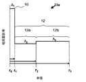
光ファイバは一般に、光の伝送のためのコアファイバと、コア内の伝送された光を保持して、距離による伝送損失を低減することを目的とする、1つ以上のクラッド層とからなる。例示的な段階的屈折率光ファイバを、図1Aに示す。光ファイバ11aは、コア10、内側クラッド12a及び外側クラッド12bを含む。図1Aの光ファイバ11aに関する相対屈折率プロファイルを図2Aに示す。コア10は、コア中心r0からコア外縁部r1まで径方向に延在し、屈折率Δ1を有する。内側クラッド12aは、コア外縁部r1から径方向距離r2まで径方向に延在し、屈折率Δ2を有する。外側クラッド12bは、r2から、r3にあるファイバの外縁部まで径方向に延在し、屈折率Δ3を有する。
An optical fiber generally comprises a core fiber for transmitting light and one or more clad layers intended to retain the transmitted light in the core and reduce transmission loss due to distance. An exemplary stepwise refractive index optical fiber is shown in FIG. 1A. The
本明細書の記載から、本発明に従って代替的な好適な構成の光ファイバを形成できることが理解されるだろう。いくつかの実施形態では、内側クラッド領域と外側クラッド領域との間に、12tで示されるトレンチ領域が存在する。トレンチ領域は、曲げ損失に対する光ファイバの感受性を低減する。このようなプロファイルの例を、光ファイバ11bとして図1Bに示し、この光ファイバ11bは、図2Bに示す相対屈折率プロファイルを有する。図2Bでは、コア10は、コア中心r0からコア外縁部r1まで径方向に延在し、屈折率Δ1を有する。内側クラッド12aは、コア外縁部r1から径方向距離r2まで径方向に延在し、屈折率Δ2を有する。トレンチ領域12tは、r2からr4まで径方向に延在し、屈折率Δ4を有する。外側クラッド12bは、r4から、r3にあるファイバの外縁部まで径方向に延在し、屈折率Δ3を有する。外側クラッド領域の屈折率Δ3は、外側クラッド領域のアップドープの結果として、内側クラッド領域の屈折率Δ2より高い。トレンチ領域12tの屈折率Δ4は、上記領域をダウンドーパントでドープすることによって達成される。
From the description herein, it will be appreciated that alternative suitable configurations of optical fibers can be formed according to the present invention. In some embodiments, there is a trench region, represented by 12t, between the inner clad region and the outer clad region. The trench region reduces the sensitivity of the optical fiber to bending loss. An example of such a profile is shown in FIG. 1B as an
本説明は:コア‐クラッド比が大きいコアケーンから形成された光ファイバプリフォーム;上記光ファイバプリフォームの作製に使用される中間コア‐クラッド組立体;上記プリフォームを作製するためのプロセス;及び上記プリフォームからドロー形成された光ファイバを提供する。 The description is: an optical fiber preform formed from a core cane with a large core-clad ratio; an intermediate core-clad assembly used to make the fiber optic preform; a process for making the preform; and the above. An optical fiber drawn from a preform is provided.
光ファイバプリフォームは、コアケーンと、上記コアケーンを取り囲む1つ以上のクラッド層とを含む。プリフォームは、コア‐クラッド組立体を加工することによって形成される。加工は、コア‐クラッド組立体の脱水、ドープ及び/又は焼結を含んでよい。コア‐クラッド組立体は、コアケーン及びスートクラッドモノリスを含み、ここで上記スートクラッドモノリスは、上記コアケーンとは独立して形成され、1つ以上の多孔性クラッド層を含む。スートクラッドモノリスは、内部キャビティを含んでよく、コア‐クラッド組立体は、コアを上記内部キャビティに挿入することによって形成してよい。焼結は、コア‐クラッド組立体の多孔性クラッド層を固結して高密度化されたクラッド層を達成し、上記高密度化されたクラッド層はコアケーンに融合して、光ファイバプリフォームを形成する。 The fiber optic preform includes a core cane and one or more clad layers surrounding the core cane. The preform is formed by processing the core-clad assembly. Processing may include dehydration, doping and / or sintering of the core-clad assembly. The core-clad assembly comprises a core cane and a soot clad monolith, wherein the soot clad monolith is formed independently of the core cane and includes one or more porous clad layers. The soot-clad monolith may include an internal cavity and the core-clad assembly may be formed by inserting the core into the internal cavity. Sintering achieves a densified clad layer by consolidating the porous clad layer of the core-clad assembly, and the densified clad layer fuses with the core cane to form an optical fiber preform. Form.
光ファイバプリフォームは、欠陥の形成を最小化するケーン・イン・スートプロセスから作製される。光ファイバプリフォームは本質的に欠陥を含まず、ファイバドロー形成温度への再加熱に、割れを発生させることなく耐えることができる。ケーン・イン・スートプロセスでは、コアケーン及びスートクラッドモノリスは互いに独立して形成される。コアケーンは、固結済みガラス本体である。スートクラッドモノリスは多孔性であり、内部キャビティを含む。コアケーンの少なくとも一部分を内部キャビティに挿入して、コア‐クラッド組立体を形成する。コア‐クラッド組立体は中間構造体であり、これを後に固結させて光ファイバプリフォームを形成する。 Fiber optic preforms are made from a cane-in-suit process that minimizes defect formation. Fiber optic preforms are inherently defect-free and can withstand reheating to fiber draw formation temperatures without cracking. In the cane-in-suit process, core canes and soot-clad monoliths are formed independently of each other. The core cane is a consolidated glass body. The soot-clad monolith is porous and contains an internal cavity. At least a portion of the core cane is inserted into the internal cavity to form a core-clad assembly. The core-clad assembly is an intermediate structure that is later consolidated to form a fiber optic preform.
コアケーンの製作は、コアスートプリフォームの形成で開始できる。図1は、コアスートプリフォームが形成される。図1は、ハンドル13を有する例示的なコアスートプリフォーム8を示す。コアスートプリフォーム8は、化学蒸着(chemical vapor deposition:CVD)(例えば外側蒸着(outside vapor deposition:OVD)、軸蒸着(vapor axial deposition:VAD)、改質化学蒸着(modified chemical vapor deposition:MCVD)、プラズマ化学蒸着(plasma chemical vapor deposition:PCVD))、又はゾル‐ゲル加工若しくは火炎加水分解といった他のいずれの好適な技法等の、いずれの好適な方法を用いて形成してよい。コアスートプリフォーム8は、純粋なシリカ又はドープシリカ(例えば、ゲルマニア、ホウ素、フッ素、アルミニウム、チタン、リン及び/若しくは塩素を含むがこれらに限定されない、1つ若しくは複数の好適なドーパントでドープされたシリカ)から形成してよい。ドープを使用して、コアスートプリフォームの屈折率を制御してよい。コアケーンの屈折率プロファイルは、定常プロファイル、段階的屈折率プロファイル、又は単調変化性プロファイル(例えばα‐プロファイル若しくはスーパーガウス型プロファイル)であってよい。コアスートプリフォームは、単層又は複層体として形成してよく、ここで上記1つ以上の層はドープされてよく、ドープされていなくてもよく、またドープされている場合は、上記1つ以上の層は、ドーパントのタイプ、濃度又は分布について違いを含んでいてよい。コアスートプリフォーム8は、複数の隙間を画定する多孔性構造体である。コアスートプリフォーム8は、その全長に亘って延在する通路を含んでよく、上記通路から、堆積装置のマンドレルが除去されている。いくつかの実施形態によると、コアスートプリフォーム8の密度は約1.0g/cc以下、好ましくは約0.7g/cc以下、より好ましくは約0.6g/cc以下である。
The production of the core cane can be started by forming the core suit preform. In FIG. 1, a core suit preform is formed. FIG. 1 shows an exemplary
コアスートプリフォーム8を固結させて、固結済みコアガラスプリフォームを形成し、上記固結済みコアガラスプリフォームをドロー形成して、コアケーンを形成する。コアスートプリフォーム8の固結は焼結を含み、また乾燥及び/又はドープといった他のプロセスステップを含んでよい。コアスートプリフォーム8の固結は、本明細書に記載の方法に適合するいずれの好適な又は望ましいプロセス又はパラメータを採用してよい。コアスートプリフォーム8の固結及び固結済みコアスートプリフォームのドロー形成に好適な装置は、当業者には公知である。
The
スートクラッドモノリスを、コアケーンとは独立して形成する。スートクラッドモノリスを、コアケーンとは独立して形成することによって、コアケーンは、スートクラッドの堆積反応又は堆積後加工における反応物又は副産物として存在する水に曝露されない。これはコアケーンの再湿潤化を防止し、ファイバプリフォームの、及びプリフォームからドロー形成されたファイバ中の、ヒドロキシル含有量の削減につながる。結果として、ヒドロキシル吸収による1380nmにおける減衰が大幅に低減される。 The soot-clad monolith is formed independently of the core cane. By forming the soot-clad monolith independently of the core cane, the core cane is not exposed to water present as a reactant or by-product in the deposition reaction or post-deposition processing of the soot-clad. This prevents rewetting of the core cane and leads to a reduction in hydroxyl content in the fiber preform and in the fiber drawn from the preform. As a result, the attenuation at 1380 nm due to hydroxyl absorption is significantly reduced.
スートクラッドモノリスは、シリカスート又はドープシリカスートの1つ以上の層を基材上に堆積させ、上記基材を除去してスートクラッドモノリスを提供することによって形成してよい。上記基材は、ベイトロッドであってよい。クラッドスート(又はその層)は、純粋なシリカ、又はドープシリカ(例えば、ゲルマニア、ホウ素、フッ素、アルミニウム、チタン、リン及び/若しくは塩素を含むがこれらに限定されない、1つ若しくは複数の好適なドーパントでドープされたシリカ)で形成してよい。上述のように、クラッドスートは、ドープ及び屈折率が異なる複数の層を含んでよく、これにより、図2A及び2Bに示されているもののような、複数のクラッド領域を含むファイバ屈折率プロファイルがもたらされる。 The soot-clad monolith may be formed by depositing one or more layers of silica soot or doped silica soot on a substrate and removing the substrate to provide the soot-clad monolith. The base material may be a bait rod. The clad soot (or layer thereof) may be pure silica, or doped silica (eg, one or more suitable dopants including, but not limited to, germania, boron, fluorine, aluminum, titanium, phosphorus and / or chlorine. It may be formed of doped silica). As mentioned above, the clad suit may include multiple layers with different dope and index of refraction, which results in a fiber index profile containing multiple clad regions, such as those shown in FIGS. 2A and 2B. Brought to you.
以下の議論では、3つの多孔性スートクラッド層を有するスートクラッド層の製作について記載する。しかしながら、概説される手順は、いずれの数の多孔性スートクラッド層を有するスートクラッドモノリスに広く適用可能であることを認識されたい。 The following discussion describes the fabrication of soot-clad layers with three porous soot-clad layers. However, it should be recognized that the procedures outlined are widely applicable to soot-clad monoliths with any number of porous soot-clad layers.
図4は、ベイトロッド120上のシリカ系スート層112の堆積を示す。シリカ系ガラススートは、SiCl4又はオクタメチルシクロテトラシロキサン(OMCTS)といった気相シリカ系ガラス前駆体材料をバーナ122に供給することによって形成される。ガスを供給されたバーナ122に、H2、CH4、D2(重水素)、CD4又はCO等の燃料を提供する。バーナ122に酸素も供給し、燃料及び酸素を燃焼させて、火炎126を生成する。いくつかの実施形態では、気相シリカ系ガラス前駆体材料はSiCl4であり、ガスを供給されたバーナ122には、堆積させたシリカ系ガラススート中の残留OHの量を制限するために、D2、CD4又はCOといった非水素化燃料を供給する。気相シリカ系ガラス前駆体材料は、約4L/分〜約10L/分の流量でバーナへと送達してよく、燃料は、約10L/分〜約40L/分の流量でバーナに供給してよい。
FIG. 4 shows the deposition of silica-based
気相シリカ系ガラス前駆体材料は、火炎126中で反応して、シリカ系ガラススート128を産生し、これは、ベイトロッドが回転するに従って、ベイトロッド120上にスート層112として堆積される。回転速度は、約20rpm〜約400rpm、又は30rpm〜約100rpmであってよい。スート層112は、非ドープシリカと同一の、非ドープシリカより高い、又は非ドープシリカより低い屈折率を有してよい。高い又は低い屈折率は、アップドーパント又はダウンドーパント前駆体をバーナ122に供給することによって達成できる。スート層112は、単層スートクラッドモノリスを構成してよく、又は多層スートクラッドモノリスの最内(最小半径)層を構成してよい。ガスを供給されたバーナ122の火炎126は、ベイトロッドが回転するに従って、矢印124で示されるようなベイトロッド120の軸方向長さに沿って前後に横断し、これにより、シリカ系ガラススートが構成され、ベイトロッド120上にスート層112が形成される。
The vapor phase silica-based glass precursor material reacts in
図5は、スート層112上のスート層116の堆積を示す。スート層116は、スート層112と同様の方法で形成できる。例えば、SiCl4又はOMCTSといった気相シリカ系ガラス前駆体材料をバーナ122に供給し、火炎126中で反応させて、シリカ系ガラススートを形成でき、これは、ベイトロッドが回転するに従ってスート層112上にスート層116として堆積される。スート層116は、スート層112と同一の、スート層112より高い、又はスート層112より低い屈折率を有してよい。図2Aの2層クラッド領域を有するファイバのドロー形成を可能とするプリフォームを達成するためには、例えばスート層112をアップドープシリカとしてよく、またスート層116をアップドープシリカとしてよい。スート層116は、2層スートクラッドモノリスの外側層、又は3つ以上の層を有するスートクラッドモノリスの中間層を構成してよい。
FIG. 5 shows the deposition of the
図6は、スート層116上のスート層114の堆積を示す。スート層114は、スート層112又はスート層116と同様の方法で形成できる。例えば、SiCl4又はオクタメチルシクロテトラシロキサン(OMCTS)といった気相シリカ系ガラス前駆体材料をバーナ122に供給し、火炎126中で反応させて、シリカ系ガラススートを形成でき、これは、ベイトロッドが回転するに従ってスート層116上にスート層114として堆積される。スート層114は、スート層116若しくはスート層112と同一の、スート層116若しくはスート層112より高い、又はスート層116若しくはスート層112より低い屈折率を有してよい。図2Bの3層クラッド領域を有するファイバのドロー形成を可能とするプリフォームを達成するためには、例えばスート層112をアップドープシリカとしてよく、スート層116をダウンドープシリカとしてよく、またスート層114をアップドープシリカとしてよい。スート層114は、3層スートクラッドモノリスの外側層、又は4つ以上の層を有するスートクラッドモノリスの中間層を構成してよい。追加の層を同様に堆積させることによって、いずれの所望の数の層を有するスートクラッドモノリスを得ることができる。
FIG. 6 shows the deposition of the
多層スートクラッドモノリスの異なる複数の層を形成するために使用されるプロセス条件は、同一であっても異なっていてもよい。プロセス変数としては、火炎温度、ケイ素又はドーパントのための前駆体の流量、ベイト基材の長さに沿ったバーナの横断速度、及びベイト基材の回転速度が挙げられる。プロセス条件の変動によって、スートの堆積速度、及び堆積させたままの状態でのスートの密度を制御できる。火炎温度は、1500℃以上であってよい。火炎温度が高いほど、堆積させたままのスートの密度を高くすることができる。反対に、火炎温度が低いほど、堆積させたままのスートの密度は低くなる。 The process conditions used to form different layers of the multilayer soot-clad monolith may be the same or different. Process variables include flame temperature, precursor flow rate for silicon or dopant, burner crossing speed along the length of the bait substrate, and rotation speed of the bait substrate. Fluctuations in process conditions can control the rate of suit deposition and the density of suits in the as-deposited state. The flame temperature may be 1500 ° C. or higher. The higher the flame temperature, the higher the density of the as-deposited suit. Conversely, the lower the flame temperature, the lower the density of the as-deposited suit.
スート密度は、ベイト基材に沿ったバーナの横断の速度によっても影響され得る。火炎の横断速度は、0.1cm/秒超、又は0.25cm/秒超、又は0.5cm/秒超、又は1cm/秒超、又は2cm/秒超、又は3cm/秒超であってよい。横断速度がより速いと、堆積させたままの状態において密度がより低く、より多孔性のスート層がもたらされ得る。反対に、横断速度がより遅いと、堆積させたままの状態において密度がより高く、多孔性がより低いスート層がもたらされ得る。堆積させたままの状態のスート層の密度は、1.0g/cm3未満、又は0.8g/cm3未満、又は0.6g/cm3未満、又は0.5g/cm3未満であってよい。堆積させたままの状態のスート層の密度は、1.0g/cm3超、又は1.25g/cm3超、又は1.5g/cm3超、又は1.75g/cm3超、又は2.0g/cm3超であってよい。 Soot density can also be affected by the speed of crossing the burner along the bait substrate. The crossing speed of the flame may be greater than 0.1 cm / sec, or greater than 0.25 cm / sec, or greater than 0.5 cm / sec, or greater than 1 cm / sec, or greater than 2 cm / sec, or greater than 3 cm / sec. .. Higher crossing velocities can result in lower densities and more porous soot layers in the as-deposited state. Conversely, slower crossing velocities can result in a denser, less porous soot layer in the as-deposited state. The density of the soot layer in the as-deposited state is less than 1.0 g / cm 3 , or less than 0.8 g / cm 3 , or less than 0.6 g / cm 3 , or less than 0.5 g / cm 3. good. The density of the soot layer in the as-deposited state is more than 1.0 g / cm 3 or more than 1.25 g / cm 3 or more than 1.5 g / cm 3 or more than 1.75 g / cm 3 or 2 It may be more than 0.0 g / cm 3.
堆積させたままの状態のスート層密度は、バーナへのスート前駆体の送達速度によっても影響され得る。シリカ系スート前駆体の流量は、0.1L/分〜20L/分の範囲内であってよい。流量が低いほど、堆積させたままの状態において密度がより高いスート層の形成が促進される。反対に、流量が高いほど、堆積させたままの状態において密度がより低いスート層の形成が促進される。 The density of the soot layer in the as-deposited state can also be affected by the rate of delivery of the soot precursor to the burner. The flow rate of the silica-based soot precursor may be in the range of 0.1 L / min to 20 L / min. Lower flow rates promote the formation of denser soot layers in the as-deposited state. Conversely, higher flow rates promote the formation of less dense soot layers in the as-deposited state.
堆積させたままの状態のスート層密度は、スート堆積中のベイトロッドの回転速度によっても影響され得る。ベイトロッドの回転速度を低下させることにより、堆積させたままの状態のスート層の密度の上昇を支援できる。反対に、ベイトロッドの回転速度を増大させることにより、堆積させたままの状態のスート層の密度の低下を支援できる。 The density of the soot layer in the as-deposited state can also be affected by the rotational speed of the bait rod during soot deposition. By reducing the rotation speed of the bait rod, it is possible to support an increase in the density of the soot layer in the as-deposited state. On the contrary, by increasing the rotation speed of the bait rod, it is possible to support the decrease in the density of the soot layer in the as-deposited state.
一実施形態では、スートクラッドモノリスは2つのスート層を含み、ここで外側層は、内側層よりも高い密度を有する。別の実施形態では、スートクラッドモノリスは3つのスート層を含み、ここで中間スート層は、内側スート層と外側スート層との間に位置決めされ、上記中間スート層は、上記内側スート層よりも高い密度を有する。更に別の実施形態では、スートクラッドモノリスは4つ以上のスート層を含み、ここで2つ以上の中間スート層が、内側スート層と外側スート層との間に位置決めされ、上記中間スート層のうちの少なくとも1つは、上記内側スート層よりも高い密度を有する。 In one embodiment, the soot-clad monolith comprises two soot layers, where the outer layer has a higher density than the inner layer. In another embodiment, the soot-clad monolith comprises three soot layers, where the intermediate soot layer is positioned between the inner soot layer and the outer soot layer, the intermediate soot layer being more than the inner soot layer. Has a high density. In yet another embodiment, the soot-clad monolith comprises four or more soot layers, where two or more intermediate soot layers are positioned between the inner soot layer and the outer soot layer of the intermediate soot layer. At least one of them has a higher density than the inner soot layer.
所望の数及びタイプのスートクラッド層を堆積させた後、ベイトロッドを除去して、スートクラッドモノリスを提供する。ベイトロッドが占有していた空間は、スートクラッドモノリスの内部キャビティを形成する。 After depositing the desired number and type of soot-clad layers, the bait rods are removed to provide the soot-clad monolith. The space occupied by the bait rod forms the internal cavity of the soot-clad monolith.
ケース・イン・スートプロセスでは、コアケーンをスートクラッドモノリスの内部キャビティに挿入して、コア‐クラッド組立体を形成する。 In the case-in-suit process, the core cane is inserted into the inner cavity of the soot-clad monolith to form a core-clad assembly.
図7は、固結炉130内へのスートクラッドモノリス110の配置を示す。スートクラッドモノリス110は、ベイトロッド120を除去した後の、図6に示す3層スート構造体に対応し、上述のように一連の同心スート層112、116及び114を含む。スートクラッドモノリス110は更に、内部キャビティ118を含む。図7の実施形態では、内部キャビティ118は、スートクラッドモノリス110の全長を通って延在する。他の実施形態では、内部キャビティ118はスートクラッドモノリス110内に、部分的にのみ延在する。高密度化されたコアケーン102を内部キャビティ118に挿入して、コア‐クラッド組立体を形成する。コア‐クラッド組立体は、コアケーン102の外側表面とスートクラッド層112の内側表面との間に間隙を含む。コア‐クラッド組立体を、固結炉130内で加工する。
FIG. 7 shows the arrangement of the soot-clad
コア‐クラッド組立体を、本明細書に記載の方法に従って加工して、光ファイバプリフォームを形成する。上述のように、この加工は固結を含み、コア‐クラッド組立体の1つ以上の多孔性スートクラッド層のスート‐ガラス変換を実施する。加工は、予備加熱ステップ、中間加熱ステップ、及び焼結ステップを含んでよく、ここで上記予備加熱ステップ、中間加熱ステップ、及び焼結ステップのうちの1つ以上は、還元剤によるスートクラッドプリフォームの処理を含んでよい。スートクラッドプリフォームの加工は、乾燥ステップ及びドープステップも含んでよい。 The core-clad assembly is processed according to the methods described herein to form fiber optic preforms. As mentioned above, this process involves consolidation and carries out a soot-glass conversion of one or more porous soot-clad layers of the core-clad assembly. The process may include a preheating step, an intermediate heating step, and a sintering step, wherein one or more of the preheating step, the intermediate heating step, and the sintering step is a soot clad preform with a reducing agent. May include the processing of. Processing of the soot-clad preform may also include a drying step and a dope step.
加工が乾燥ステップを含む実施形態では、コア‐クラッド組立体を乾燥剤で処理する。この乾燥ステップは、約800℃〜1300℃の温度で実施してよく、上述の予備加熱ステップ及び中間加熱ステップのうちの一方又は両方を含む。乾燥剤は、コア‐クラッド組立体の多孔性スートクラッド層の細孔に浸透して、水又はOH基と反応し、多孔性スートクラッド層から水及びOH基を除去する。乾燥剤は、多孔性スートクラッド層中に存在し得る遷移金属又は他の不純物も除去できる。 In embodiments where processing involves a drying step, the core-clad assembly is treated with a desiccant. This drying step may be performed at a temperature of about 800 ° C. to 1300 ° C. and includes one or both of the preheating step and the intermediate heating step described above. The desiccant penetrates the pores of the porous soot-clad layer of the core-clad assembly and reacts with water or OH groups to remove water and OH groups from the porous soot-clad layer. The desiccant can also remove transition metals or other impurities that may be present in the porous soot clad layer.
図7を参照すると、乾燥剤は、流路132によって示されるように、コアケーン102の外側表面とスートクラッド層112の内側表面との間の間隙に入ることができる。乾燥剤は、スート層112、116及び114内の細孔にも入ることができ、また流路134によって示されるように、スートクラッド層114の外側表面を取り囲む、又は上記外側表面の周りを通過することもできる。コア‐クラッド組立体を通った、及び/又はコア‐クラッド組立体の周りの、乾燥剤の流量は、約1L/分〜約40L/分の範囲内であってよい。コア‐クラッド組立体は、脱水中に加熱してよい。加熱は乾燥剤の作用を更に進めることができ、ヒドロキシル及び水の除去を促進できる。
With reference to FIG. 7, the desiccant can enter the gap between the outer surface of the
脱水の温度は、約500℃〜約1300℃の範囲内としてよく、脱水の時間は、30分〜10時間の範囲内としてよい。脱水の温度は好ましくは、コア‐クラッド組立体のスートクラッドモノリス構成成分の焼結を開始するために必要な温度未満である。スートクラッドモノリスの不十分な焼結は、細孔を閉鎖し、スートクラッドモノリスの内部への脱水剤のアクセスをブロックすることにより、ヒドロキシル及び水の除去を阻害する。乾燥剤は、脱水が完了するとすぐに、スートクラッドモノリス及び/又はコア‐クラッド組立体を取り囲む環境から除去してよい。 The dehydration temperature may be in the range of about 500 ° C. to about 1300 ° C., and the dehydration time may be in the range of 30 minutes to 10 hours. The dehydration temperature is preferably below the temperature required to initiate sintering of the soot-clad monolithic components of the core-clad assembly. Inadequate sintering of the soot-clad monolith inhibits the removal of hydroxyl and water by closing the pores and blocking the access of the dehydrating agent to the interior of the soot-clad monolith. The desiccant may be removed from the environment surrounding the soot-clad monolith and / or core-clad assembly as soon as dehydration is complete.
好適な乾燥剤は、Cl2、SiCl4、GeCl4、SOCl2及び/又はPOCl3といった塩素含有ガスを含む。乾燥剤は任意に、He、Ar、Ne及び/又はN2といった不活性ガス中で希釈してよい。一実施形態では、脱水ガスは、ヘリウムガス中の2%〜6%の塩素ガスの混合物を含む。いくつかの実施形態では、乾燥ガスは、約5体積%未満の塩素、例えば約0.01〜3.0体積%の塩素を含有する。 Suitable desiccants include chlorine-containing gases such as Cl 2 , SiCl 4 , GeCl 4 , SOCL 2 and / or POCl 3. The desiccant may optionally be diluted in an inert gas such as He, Ar, Ne and / or N 2. In one embodiment, the dehydrated gas comprises a mixture of 2% to 6% chlorine gas in helium gas. In some embodiments, the dry gas contains less than about 5% by volume chlorine, such as about 0.01-3.0% by volume chlorine.
いくつかの実施形態では、加工はドープステップを含んでよく、上記ドープステップでは、コア‐クラッド組立体をドーパント前駆体に曝露する。一実施形態では、ドープは、スート‐ガラス変形プロセスの予備加熱ステップ中に実施される。別の実施形態では、ドープは、中間加熱ステップ中に実施される。更に別の実施形態では、ドープは、スート‐ガラス変形プロセスの焼結ステップ中に実施される。ドープは好ましくは、コア‐クラッド組立体のクラッド層が、ドーパント又はドープ前駆体の拡散又は浸透が可能となるよう十分に多孔性である間に行われる。一実施形態では、ドープは、脱水後かつ焼結前に行われる。 In some embodiments, the process may include a dope step, in which the core-clad assembly is exposed to a dopant precursor. In one embodiment, the dope is performed during the preheating step of the soot-glass deformation process. In another embodiment, the dope is performed during the intermediate heating step. In yet another embodiment, the dope is performed during the sintering step of the soot-glass deformation process. Doping is preferably carried out while the clad layer of the core-clad assembly is sufficiently porous to allow diffusion or penetration of the dopant or dope precursor. In one embodiment, the doping is done after dehydration and before sintering.
一実施形態では、ドープは、コア‐クラッド組立体内のコアケーンの外側表面とスートクラッドモノリスの内側表面との間の流路にドープ前駆体を供給することによって達成される。例えば、ドープ前駆体を、図7に示す流路132に供給してよい。別の実施形態では、ドープは、コア‐クラッド組立体のスートクラッドモノリス構成成分の外側スート層の外側表面に隣接する流路にドープ前駆体を供給することによって達成される。例えば、ドープ前駆体を、図7に示す流路134に供給してよい。
In one embodiment, dope is achieved by supplying a dope precursor to the flow path between the outer surface of the core cane in the core-clad assembly and the inner surface of the soot-clad monolith. For example, the dope precursor may be supplied to the
ドープ前駆体を、コア‐クラッド組立体のスートクラッドモノリス構成成分の多孔性スート層に供給すると、ドープ前駆体は細孔に入って、スート層の表面へ、及び/又はスート層の内部全体にわたって、ドーパントを送達できる。ドープは、コア‐クラッド組立体のスートクラッドモノリス部分の複数の層において行うことができる。 When the dope precursor is fed into the porous soot layer of the soot-clad monolith component of the core-clad assembly, the dope precursor enters the pores and / or throughout the interior of the soot layer. , The dopant can be delivered. Doping can be done in multiple layers of the soot-clad monolith portion of the core-clad assembly.
コア‐クラッド組立体の焼結は、脱水後に行ってよい。乾燥剤及び/又はドーパント前駆体は、焼結の開始前に、コア‐クラッド組立体の雰囲気から除去してよい。 Sintering of the core-clad assembly may be performed after dehydration. The desiccant and / or dopant precursor may be removed from the atmosphere of the core-clad assembly prior to the start of sintering.
上記焼結は、スートクラッドモノリスを固結させ、スートクラッドモノリスとコアケーンとを融合させて、固結済みファイバプリフォームを形成できる。焼結中、スートクラッドモノリスの細孔が収縮し、スートクラッドモノリスが収縮してコアケーンに付着するため、高密度化が起こる。焼結温度は、少なくとも1300℃、又は少なくとも1350℃、又は少なくとも1400℃、又は少なくとも1450℃、又は少なくとも1500℃であってよい。焼結温度が高いほど、焼結の時間が削減される。 The sintering can consolidate the soot-clad monolith and fuse the soot-clad monolith with the core cane to form a consolidated fiber preform. During sintering, the pores of the soot-clad monolith shrink, and the soot-clad monolith shrinks and adheres to the core cane, resulting in high density. The sintering temperature may be at least 1300 ° C, or at least 1350 ° C, or at least 1400 ° C, or at least 1450 ° C, or at least 1500 ° C. The higher the sintering temperature, the shorter the sintering time.
焼結は、固結炉内での焼結を誘発するために十分な温度の高温領域を形成して、コア‐クラッド組立体を、温度が1400℃〜約1500℃の範囲であってよい炉内の熱サイクルに曝露することにより、固結炉内で達成できる。コア‐クラッド組立体を焼結することにより、光ファイバプリフォームが製造される。図8は、図7のコア‐クラッド組立体を焼結することによって形成された、光ファイバプリフォーム100を示す。上記光ファイバプリフォームは、1つ以上の同心クラッド領域で取り囲まれた、1つ以上の同心領域を有する中心コアを有する、ガラスの中実片である。
Sintering forms a hot region at a temperature sufficient to induce sintering in the consolidation furnace, allowing the core-clad assembly to be in the range of temperatures from 1400 ° C to about 1500 ° C. This can be achieved in the consolidation furnace by exposure to the heat cycle within. Fiber optic preforms are manufactured by sintering the core-clad assembly. FIG. 8 shows an
光ファイバを、光ファイバプリフォームからドロー形成できる。固結済みガラスプリフォームから光ファイバをドロー形成するための好適な技法及び装置は、当業者には公知である。上記固結済み光ファイバプリフォームの固結済みガラスコアは、光ファイバのコア(又はコアの一部)を形成することになり、上記固結済み光ファイバプリフォームの固結済みクラッド層は、光ファイバのクラッド部分を形成することになることが理解されるだろう。 An optical fiber can be drawn from an optical fiber preform. Suitable techniques and devices for drawing optical fibers from consolidated glass preforms are known to those of skill in the art. The consolidated glass core of the consolidated optical fiber preform forms the core (or a part of the core) of the optical fiber, and the consolidated clad layer of the consolidated optical fiber preform is It will be understood that it will form a clad portion of the optical fiber.
ケーン・イン・スートプロセスで調製された光ファイバプリフォームの点検により、ドロー中にプリフォームの破損につながり得る欠陥の存在が明らかになっている。欠陥は割れを含み、これは、ファイバドロー形成のためにプリフォームを溶融するために必要な温度までの再加熱プロセスの早期における、光ファイバプリフォームの破断につながり得る。上述のように、ケース・イン・スートプロセスを用いた光ファイバプリフォームの製作は、高温でのコア‐クラッド組立体の固結を含む。固結プロセスで形成された光ファイバプリフォームは室温まで冷却され、ファイバドロー形成の時まで保管される。 Inspection of fiber optic preforms prepared by the cane-in-suit process reveals the presence of defects during the draw that can lead to preform breakage. Defects include cracking, which can lead to breakage of the fiber optic preform early in the reheating process to the temperature required to melt the preform for fiber draw formation. As mentioned above, the fabrication of fiber optic preforms using the case-in-suit process involves consolidation of the core-clad assembly at elevated temperatures. The fiber optic preform formed by the consolidation process is cooled to room temperature and stored until the time of fiber draw formation.
理論によって束縛されることを望むものではないが、固結温度から室温(又は他の比較的低い温度)への光ファイバプリフォームの冷却が、光ファイバプリフォーム中の欠陥の形成につながると考えられる。更に、欠陥は、コアケーン及びスートクラッドモノリスの熱膨張係数の差異から発生する応力に起因するものと考えられる。上述のように、コアケーンは典型的にはアップドープシリカから形成され、クラッドは典型的には、非ドープシリカ、又は非ドープシリカとダウンドープシリカとの組み合わせから形成される。コアケーン及びスートクラッドモノリスに使用される材料間に存在する組成の差異は、熱膨張係数の差異を含意しており、これは、固結後の冷却中の、光ファイバプリフォームのコア及びクラッド領域の収縮の速度又は程度の差異につながる。熱収縮の差異は、冷却中に、コアケーンとスートクラッドモノリスとの間の界面に、応力を生成する。上記応力は、割れ又は微小割れ等の欠陥を光ファイバプリフォーム内に形成するために十分なものであると考えられる。 Although not desired to be bound by theory, it is believed that cooling the fiber optic preform from the consolidation temperature to room temperature (or other relatively low temperature) leads to the formation of defects in the fiber optic preform. Be done. Furthermore, the defects are considered to be due to the stress generated from the difference in the coefficient of thermal expansion of the core cane and the soot-clad monolith. As mentioned above, core canes are typically formed from up-doped silica and clad is typically formed from non-doped silica or a combination of non-doped silica and down-doped silica. Differences in composition present between the materials used for the core cane and soot clad monolith imply differences in the coefficient of thermal expansion, which is the core and clad region of the fiber optic preform during cooling after consolidation. It leads to a difference in the rate or degree of contraction of. The difference in heat shrinkage creates stress at the interface between the core cane and the soot-clad monolith during cooling. The above stress is considered to be sufficient to form defects such as cracks or microcracks in the optical fiber preform.
冷却誘発型(cooling‐induced)欠陥の形成は、ケース・イン・スートプロセスにおいて、コア‐クラッド比が大きいコアケーンを用いて光ファイバプリフォームを形成する際に特に見られると予想される。コア‐クラッド比が大きいコアケーンでは、アップドープ(高屈折率)領域の半径は、コアケーンの総半径の有意な部分を占める。アップドープ領域の径方向範囲が大きいと、アップドープ領域の境界が、組成が一致しないスートクラッド組立体の付近に位置決めされ、冷却中の光ファイバプリフォームのコア及びクラッド領域の収縮の差異から発生する応力が増大する。例えばコア‐クラッド比が1である場合、コアはクラッドに直接隣接し、コアケーンとクラッドとの間の熱膨張係数の差異が最もよく現れる。対照的に、コア‐クラッド比が小さいコアケーンを使用する場合、アップドープ領域は、コアケーンとスートクラッドモノリスとの間の界面から除去され、クラッドの熱膨張係数にかなり一致する非ドープ材料で取り囲まれる。その結果、収縮によって発生する熱応力は比較的現れず、冷却時に形成される欠陥が少なくなる。 The formation of cooling-induced defects is expected to be particularly seen in the case-in-suit process when forming fiber optic preforms with core canes with high core-clad ratios. For core canes with a large core-clad ratio, the radius of the up-doped region occupies a significant portion of the total radius of the core cane. When the radial range of the updoping region is large, the boundary of the updoping region is positioned near the soot clad assembly where the composition does not match, and it arises from the difference in shrinkage of the core and clad region of the fiber optic preform during cooling. The stress to be applied increases. For example, when the core-clad ratio is 1, the core is directly adjacent to the clad, and the difference in the coefficient of thermal expansion between the core cane and the clad is most apparent. In contrast, when using core canes with a low core-clad ratio, the up-doped region is removed from the interface between the core cane and the soot-clad monolith and surrounded by a non-doped material that closely matches the coefficient of thermal expansion of the clad. .. As a result, the thermal stress generated by shrinkage does not appear relatively, and the number of defects formed during cooling is reduced.
図9(a)〜(c)は、平坦な端部表面を有するコアケーンを用いてケース・イン・スートプロセスから形成された、光ファイバプリフォームを示す。図9(a)は、光ファイバプリフォーム140を示す概略図である。光ファイバプリフォーム140は、コアケーン145と、金属ハンドル155で支持された固結済みクラッド150とを含み、この金属ハンドル155は、末端点151まで延在する。ハンドル155は、固結済みクラッド150の内部キャビティ157への入口153を通過する。コアケーン145は内部キャビティ157内に位置し、内部キャビティ157の入口153に対面する平坦な端部表面147を含む概ね円筒形の形状を有する。端部表面147とハンドル155の末端点151との間のヘッドスペースは、加工環境に存在する空気及び/又は気体に占有される。ジャンクション159は、固結済みクラッド150と、コアケーン145と、ヘッドスペース149に存在する気体との間の3方向界面を構成する。
9 (a)-(c) show fiber optic preforms formed from a case-in-suit process using core canes with flat end surfaces. FIG. 9A is a schematic view showing the
図9(b)及び9(c)は、図9(a)に示されている概略図と同一の光ファイバプリフォームの図を示す。プリフォームはケース・イン・スートプロセスで調製した。図9(b)に示す図は、固結後かつ冷却前の、昇温(1050℃)時のプリフォームの画像である。図9(b)に示す画像は、冷却前、プリフォーム内に明らかな濃度の欠陥が存在しないことを示す。図9(c)に示す画像は、室温まで冷却した後のプリフォームの画像である。図9(c)に示す画像は、冷却済みのプリフォーム中に欠陥(例えばチェック欠陥(check defect)又は「チェック(check)」)が存在することを示す。チェック欠陥を有する光ファイバプリフォームを、ファイバのドロー形成のためにドロー形成温度まで再加熱すると、光ファイバプリフォームは、欠陥から発生する剪断、割れの伝播又は他の力によって破断し得る。破断は光ファイバプリフォームの破損につながり、ドロー形成プロセスの中断を必要とする。 9 (b) and 9 (c) show the same fiber optic preform diagram as the schematic shown in FIG. 9 (a). The preform was prepared by a case-in-suit process. The figure shown in FIG. 9B is an image of the preform at the time of temperature rise (1050 ° C.) after consolidation and before cooling. The image shown in FIG. 9B shows that there are no apparent concentrations of defects in the preform before cooling. The image shown in FIG. 9 (c) is an image of the preform after cooling to room temperature. The image shown in FIG. 9C shows the presence of defects (eg, check defects or “checks”) in the cooled preform. When a fiber optic preform with a check defect is reheated to the draw formation temperature for fiber draw formation, the fiber optic preform can break due to shear, crack propagation or other forces resulting from the defect. Breakage leads to breakage of the fiber optic preform and requires interruption of the draw forming process.
光ファイバプリフォームの冷却中に進展する欠陥の原因は、プリフォームのコア及びクラッド領域の熱膨張係数の不一致によるものであると考えられる。上述のように、コアは典型的にはアップドープシリカ材料であり、クラッドは典型的には、非ドープシリカ又は非ドープシリカとダウンドープシリカとの組み合わせである。Geは、コア領域のための一般的なアップドーパントであり、GeドープSiO2の熱膨張係数は、非ドープシリカ又はダウンドープシリカの熱膨張係数より有意に高いことが知られている。図10は、Geドープシリカ、非ドープシリカ及びFドープシリカに関する相対屈折率Δ%の関数として、100℃〜500℃の温度間隔に亘る平均熱膨張係数を示すα100-500を示す。相対屈折率Δ%は、非ドープシリカに対する屈折率の尺度であり、ドープ濃度に比例する。正の値のΔ%はシリカのアップドープ形態を意味し、負の値のΔ%はシリカのダウンドープ形態を意味し、Δ%=0は非ドープシリカに対応する。図10のために、Geをアップドーパントとして含め、Fをダウンドーパントとして含める。図10は、Geドープシリカの熱膨張係数が、Geドープ濃度の上昇と共に増大し、非ドープシリカ及びFドープシリカ両方の熱膨張係数より高いことを示す。 It is considered that the cause of the defect that develops during the cooling of the optical fiber preform is the mismatch of the coefficient of thermal expansion of the core and the clad region of the preform. As mentioned above, the core is typically an up-doped silica material and the cladding is typically non-doped silica or a combination of non-doped silica and down-doped silica. Ge is a common uplactone for the core region, and it is known that the coefficient of thermal expansion of Ge-doped SiO 2 is significantly higher than the coefficient of thermal expansion of non-doped silica or down-doped silica. FIG. 10 shows α 100-500 showing an average coefficient of thermal expansion over temperature intervals of 100 ° C. to 500 ° C. as a function of the relative refractive index Δ% for Ge-doped silica, non-doped silica and F-doped silica. The relative index of refraction Δ% is a measure of the index of refraction for non-doped silica and is proportional to the doping concentration. A positive value of Δ% means an up-doped form of silica, a negative value of Δ% means a down-doped form of silica, and Δ% = 0 corresponds to non-doped silica. For FIG. 10, Ge is included as an up-dopant and F is included as a down-dopant. FIG. 10 shows that the coefficient of thermal expansion of Ge-doped silica increases with increasing Ge-doped concentration and is higher than the coefficient of thermal expansion of both non-doped silica and F-doped silica.
Geドープシリカについて、熱膨張係数(CTE)(単位:1/℃)及びΔ%は: For Ge-doped silica, the coefficient of thermal expansion (CTE) (unit: 1 / ° C.) and Δ% are:
![]()
![]()
及び as well as
![]()
![]()
によって、GeO2濃度[GeO2](単位:重量%)に関連付けられる。 Is associated with the GeO 2 concentration [GeO 2 ] (unit:% by weight).
図11は、Geドープシリカコア及び非ドープシリカクラッドを有する光ファイバプリフォームの、等式2から算出された、室温での熱膨張係数の、半径に対する依存を示す。Geドープシリカコアは、半径5mm及びコア‐クラッド比0.9である。Geドーパント分布は、コアの中線位置(r=0)において6.5重量%のピークドーパント濃度を有し、r=4.5mmまで略平坦のままである、段階的屈折率プロファイルに従った。クラッドは、内径5mm及び外径65mmの非ドープシリカであった。クラッドはコアと直接的に接触していた。図11は、熱膨張係数が、プリフォームのクラッド領域よりもコア領域において有意に高いことを示す。コア領域のピーク熱膨張係数は8.42×10⁷/℃であり、一方非ドープシリカの熱膨張係数は5.05×107/℃である。Geの濃度は、コア領域の半径と共に減少するが、コアの径方向外側部分の熱膨張係数は、非ドープシリカの熱膨張係数より明らかに高いままである。
FIG. 11 shows the dependence of the coefficient of thermal expansion at room temperature on the radius of an optical fiber preform having a Ge-doped silica core and a non-doped silica clad, calculated from
図12は、室温への冷却後に、ケーン・イン・スートプロセスで作製した固結済みプリフォームの端部210において算出された径方向引張応力分布を示す。端部210は、コアケーンの上部境界215付近の部分である。端部210は、コアケーン220及びクラッド240を含む。コアケーン220は円筒形であり、直径230が10mmである。コアケーン220は、GeO2をドープしたシリカから作製され、コア‐クラッド比は0.9である。GeO2のドーププロファイルは、コアの中線位置(r=0)において6.5重量%のピークドーパント濃度を有し、r=4.5mmまで略平坦のままである、段階的な屈折率である。GeO2-ドープシリカのコアケーンの熱膨張係数は、ドープ濃度の上昇と共に増大する。コアケーン220のピーク熱膨張係数は、中線(r=0)位置における7.97×10⁷/℃であり、r=4.5mmまで略平坦のままであり、その後r=4.5mmで5.05×107/℃まで低下する。クラッド240は非ドープシリカから作製され、内径が5mm、外径が65mmであった。クラッド240の、コアケーン220付近の部分のみを図12に示す。クラッド240は環状であり、コアケーン220を取り囲む。クラッド240の熱膨張係数は5.05×107/℃である。端部210はまた、占有されていない空間250を含み、これにより、プリフォームの形成中にコアケーン220が軸方向に膨張できる。
FIG. 12 shows the radial tensile stress distribution calculated at the
固結中のプリフォームの冷却中に進展する径方向引張応力を図12に示す。暗色の領域は、径方向引張応力が低い領域であり、明色の領域は、径方向引張応力が高い領域である。径方向引張応力が高い領域は、コアケーン220の中心のドープ部分、並びに円で囲まれたコーナ領域225及び235に存在する。コアケーン220のドープされていない径方向外側部分は、低い径方向引張応力を呈する。コーナ領域225及び235は、コアケーン220と、クラッド240と、占有されていない空間250内の上方の気体との間の界面のジャンクションに存在する。上方の気体は、空気、プロセスガス、不活性ガス又は他の気体であってよい。コーナ領域225及び235に存在する高い径方向引張応力は、プリフォーム内に欠陥をもたらすと考えられ、これは、ドロー形成温度への再加熱時に破断を引き起こす。
The radial tensile stress that develops during cooling of the preform during consolidation is shown in FIG. The dark-colored region is a region where the radial tensile stress is low, and the light-colored region is a region where the radial tensile stress is high. Regions with high radial tensile stress are present in the central dope portion of the
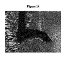
図13は、図12に示したプリフォームに関するコーナ半径の関数として、算出されたプリフォームのコーナ領域における径方向引張応力を示す。コーナ半径は、コアケーン220からクラッド240への遷移領域における端部210の表面の形状の尺度である。大きなコーナ半径は、コアケーン220からクラッド240への界面を横断する、スムーズで漸進的な遷移に対応し、その一方で小さなコーナ半径は、コアケーン220からクラッド240への界面を横断する、急峻で比較的不連続な遷移を意味する。図13は、径方向引張応力が、コーナ半径の増大と共に減少することを示している。プリフォームの製造時に典型的に使用される固結温度からの冷却速度の下では、プリフォームのコーナ半径は0.1mm未満であり、0.01mm未満である場合もある。従って、コーナ領域における径方向引張応力は高く、プリフォーム中の割れ又は他の欠陥の形成を誘発するのに十分な大きさであると思われる。図14は、欠陥を有するコーナ領域(円で囲まれた領域)を有する、Geドープシリカコアケーンの図である。
FIG. 13 shows the calculated radial tensile stress in the corner region of the preform as a function of the corner radius with respect to the preform shown in FIG. The corner radius is a measure of the surface shape of the
本開示は、ケース・イン・スートプロセスで作製された固結済みプリフォームの1つ以上のコーナ領域における径方向引張応力を最小化するための戦略を提供する。この戦略は、1つ以上のコーナ領域へのキャップの配置を含み、ここでキャッピング材料は、コアケーンの熱膨張係数より小さい熱膨張係数を有する。一実施形態では、コアケーンの熱膨張係数はクラッドの熱膨張係数より大きく、一方キャップの熱膨張係数は、コアケーンの熱膨張係数より小さく、かつクラッドの熱膨張係数より大きい。別の実施形態では、コアケーンの熱膨張係数は、クラッドの熱膨張係数より大きく、一方キャップの熱膨張係数は、クラッドの熱膨張係数と等しい。更に別の実施形態では、コアケーンの熱膨張係数はクラッドの熱膨張係数より小さく、一方キャップの熱膨張係数は、コアケーンの熱膨張係数より大きく、かつクラッドの熱膨張係数より小さい。別の実施形態では、コアケーンの熱膨張係数は、クラッドの熱膨張係数より小さく、一方キャップの熱膨張係数は、クラッドの熱膨張係数と等しい。 The present disclosure provides a strategy for minimizing radial tensile stress in one or more corner regions of a consolidated preform produced in a case-in-suit process. This strategy involves the placement of caps in one or more corner regions, where the capping material has a coefficient of thermal expansion that is less than the coefficient of thermal expansion of the core cane. In one embodiment, the coefficient of thermal expansion of the core cane is greater than the coefficient of thermal expansion of the clad, while the coefficient of thermal expansion of the cap is less than the coefficient of thermal expansion of the core cane and greater than the coefficient of thermal expansion of the clad. In another embodiment, the coefficient of thermal expansion of the core cane is greater than the coefficient of thermal expansion of the clad, while the coefficient of thermal expansion of the cap is equal to the coefficient of thermal expansion of the clad. In yet another embodiment, the coefficient of thermal expansion of the core cane is smaller than the coefficient of thermal expansion of the clad, while the coefficient of thermal expansion of the cap is greater than the coefficient of thermal expansion of the core cane and smaller than the coefficient of thermal expansion of the clad. In another embodiment, the coefficient of thermal expansion of the core cane is less than the coefficient of thermal expansion of the clad, while the coefficient of thermal expansion of the cap is equal to the coefficient of thermal expansion of the clad.
コアケーンをスートクラッドモノリスの内部キャビティに挿入してコア‐クラッド組立体を形成する前又は後に、1つ以上のキャップをコアケーンと一体化してよい。一体化された1つ以上のキャップは、コアケーンに直接的に接触してよく、コアケーンにしっかりと接合されていてよく、又はコアケーンに間接的に接触してよい。一実施形態では、キャップは、コアケーンの製造中にコアケーンの端部に形成され、ケース・イン・スートプロセスにおいて、キャッピング済みコアケーンをスートクラッドモノリスの内部キャビティに挿入する。
キャップは、コアケーンの1つ以上の端部表面への直接堆積によって、又はコアケーンをスートクラッドモノリスと一体化してコア‐クラッド組立体を形成する前に、独立して形成されたキャップをコアケーン上に融着することによって、コアケーン上に形成してよい。コアケーンは、2つ以上の端部においてキャッピングしてよい。一実施形態では、コアケーンは円筒形であり、一方又は両方の端部表面においてキャッピングされる。2つ以上のキャップをコアケーンと一体化する場合、これらのキャップは、同一の若しくは異なる組成、並びに/又は同一の若しくは異なるサイズ、形状及び/若しくは熱膨張係数を有してよい。
One or more caps may be integrated with the core cane before or after inserting the core cane into the inner cavity of the soot clad monolith to form the core-clad assembly. The one or more integrated caps may be in direct contact with the core cane, may be tightly attached to the core cane, or may be indirect contact with the core cane. In one embodiment, the cap is formed at the end of the core cane during the manufacture of the core cane and the capped core cane is inserted into the inner cavity of the soot clad monolith in a case-in-suit process.
The cap is an independently formed cap on the core cane either by direct deposition on one or more end surfaces of the core cane or before integrating the core cane with a soot-clad monolith to form a core-clad assembly. It may be formed on the core cane by fusing. The core cane may be capped at two or more ends. In one embodiment, the core cane is cylindrical and capped on one or both end surfaces. When two or more caps are integrated with the core cane, these caps may have the same or different composition and / or the same or different size, shape and / or coefficient of thermal expansion.
別の実施形態では、キャッピングされていないコアケーンをスートクラッドモノリスの内部キャビティに挿入し、1つ以上のキャップも内部キャビティ内に配置する。1つ以上のキャップは、コアケーンの1つ以上の端部表面上に直接配置してよい。あるいは、キャップを保持するため、又はプリフォームの形成プロセスにおけるコア‐クラッド組立体の固結中にキャップとコアケーンとの一体化を促進するために、コアケーンの端部表面とキャップとの間に介在材料を配置してよい。介在材料は、フラックス材料又は接着材料であってよく、コアケーン及びキャッピング材料のうちの一方又は両方の組成と同一の又は異なる組成を有してよい。介在材料は、固結されていてもいなくてもよい。一実施形態では、介在材料は、未固結SiO2スート粉体である。別の実施形態では、介在材料はSiO2スートペレットである。キャップとコアケーンとの融着及び一体化は、ケース・イン・スートプロセスにおけるコア‐クラッド組立体からのプリフォームの形成中に発生する加熱プロセス中に行われる。一実施形態では、キャップとコアケーンとの融着及び一体化は、ケース・イン・スートプロセスの焼結及び/又は固結プロセス中に行われる。 In another embodiment, an uncapped core cane is inserted into the internal cavity of the soot-clad monolith and one or more caps are also placed within the internal cavity. The one or more caps may be placed directly on the surface of one or more ends of the core cane. Alternatively, intervening between the end surface of the core cane and the cap to hold the cap or to facilitate the integration of the cap with the core cane during consolidation of the core-clad assembly during the preform forming process. Materials may be placed. The interposition material may be a flux material or an adhesive material and may have the same or different composition as one or both of the core cane and capping materials. The interposition material may or may not be consolidated. In one embodiment, the interposition material is unconsolidated SiO 2 soot powder. In another embodiment, the intervening material is SiO 2 soot pellets. The fusion and integration of the cap and core cane takes place during the heating process that occurs during the formation of the preform from the core-clad assembly in the case-in-suit process. In one embodiment, the fusion and integration of the cap and core cane is performed during the sintering and / or consolidation process of the case-in-suit process.
図15は、キャッピング済みコアケーン300を断面図で示す。キャッピング済みコアケーン300は、コアケーン310、並びにキャップ305及び315を含む。コアケーン310は円筒形であり、キャップ305及び315は、コアケーン310の端部表面に位置決めされる。図15の実施形態では、キャップ305及び315は、端部表面上に直接形成される。あるいは、キャップ305とコアケーン310との間、及び/又はキャップ315とコアケーン310との間に、介在材料(図示せず)を位置決めしてよい。キャップ305及び315は、コアケーン310と直接的に接触する。キャップ305及び315は、コアケーン310にしっかりと接合されていてよい。
FIG. 15 shows the capped
図16は、コアケーン310、キャップ305及びキャップ315からの、キャッピング済みコアケーン300の組み立てを示す。この実施形態では、コアケーン310、キャップ305及びキャップ315は独立して形成され、組み合わされてキャッピング済みコアケーン300が形成される。キャップ305とコアケーン310との間、及び/又はキャップ315とコアケーン310との間に、介在材料(図示せず)を位置決めしてよい。
FIG. 16 shows the assembly of the capped
図17は、コア‐クラッド組立体の形成を示す。キャッピング済みコアケーン300を、スートクラッドモノリス330の内部キャビティ325に挿入して、コア‐クラッド組立体335を形成する。スートクラッドモノリス330及びコア‐クラッド組立体335は断面図で示されている。スートクラッドモノリス330は、環状の多孔性スート領域320内に内部キャビティ325を含む。キャッピング済みコアケーン300は例えば、図15及び16に関連して上述した方法によって形成できる。上述のように、コアケーン310の端部表面とキャップ305との間、及び/又はコアケーン310の端部表面とキャップ315との間に、介在材料が含まれていてよい。
FIG. 17 shows the formation of a core-clad assembly. The capped
図18は、コア‐クラッド組立体335を形成するための代替的な方法を示す。コアケーン310を、スートクラッドモノリス330の内部キャビティ325に挿入する。次にキャップ305及び315を、コアケーン310の端部表面に隣接して、内部キャビティ325に挿入し、コア‐クラッド組立体335を形成する。上述のように、コアケーン310の端部表面とキャップ305との間、及び/又はコアケーン310の端部表面とキャップ315との間に、介在材料が含まれていてよい。
FIG. 18 shows an alternative method for forming the core-clad
図19は、プリフォーム345を形成するための、コア‐クラッド組立体335の固結を示す。プリフォーム345は、内部キャビティ325内にキャップ305及び315を有するコアケーン310を含む。内部キャビティ325は、環状の固結済みスート領域340で取り囲まれる。固結済みスート領域340は、完全に高密度化されたガラスである。上述のように、コアケーン310の端部表面とキャップ305との間、及び/又はコアケーン310の端部表面とキャップ315との間に、介在材料が含まれていてよい。
FIG. 19 shows the consolidation of the core-clad
1つ以上のキャップは、コアケーンの断面寸法に概ね対応する断面寸法を有してよい。例えばコアケーンが円筒形である場合、コアケーンの断面寸法は直径であり、1つ以上のキャップは、コアケーンの直径に一致するか又は概ね一致する直径を有する円筒形であってよい。コアケーン及び/又は1つ以上のキャップの断面はまた、スートクラッドモノリスの内部キャビティの断面寸法にも概ね対応してよい。 The one or more caps may have a cross-sectional dimension that roughly corresponds to the cross-sectional dimension of the core cane. For example, if the core cane is cylindrical, the cross-sectional dimension of the core cane is diameter, and one or more caps may be cylindrical with a diameter that matches or approximately matches the diameter of the core cane. The cross-section of the core cane and / or one or more caps may also roughly correspond to the cross-sectional dimensions of the internal cavity of the soot-clad monolith.
キャップの厚さは、キャップの断面寸法に対して垂直な方向である。本発明は予想外にも、
1つ以上のキャップによるプリフォーム中の欠陥の形成の抑制を、比較的薄い1つ以上のキャップを用いた場合でさえ達成できることを発見した。図20は、キャップの高さ(厚さ)の関数として、ケース・イン・スートプロセスで作製されたプリフォームのコーナ領域(図12に示すコーナ領域225及び235等)における径方向引張応力の算出された変動を示す。図20に示されている算出の基礎は、SiO2キャップを有するGeO2ドープシリカコアケーンと、シリカスートクラッドモノリスとを有するコア‐クラッド組立体を固結させることによって形成した、プリフォームである。GeO2ドープシリカコアケーンは、直径10mm及びコア‐クラッド比0.9であった。SiO2は、GeO2ドープシリカコアケーンの端部表面上に直接位置決めした。SiO2キャップは、直径10mmであり、図20に示すように様々な高さ(厚さ)を有していた。プリフォームのコーナ半径は0.2mmであった。
The thickness of the cap is in the direction perpendicular to the cross-sectional dimension of the cap. The present invention is unexpectedly
It has been found that suppression of defect formation in preform by one or more caps can be achieved even with one or more relatively thin caps. FIG. 20 shows the calculation of radial tensile stress in the corner regions (
図20に示されている結果は、径方向コーナ引張応力が、SiO2キャップの高さ(厚さ)の増大と共に有意に減少することを示す。ゼロ高さ(厚さ)におけるデータ点は、キャッピングされていないコアケーンを有するプリフォームに対応する。SiO2キャップを有しないプリフォームの径方向コーナ引張応力は、102MPaであった。径方向コーナ引張応力は高さ(厚さ)が1mm、2mm及び5mmのSiO2キャップを含めることによって、それぞれ60MPa、51MPa及び17MPaまで減少した。径方向コーナ引張応力の減少により、固結プロセス中の冷却時にプリフォーム中に欠陥が形成される可能性が低減される。 The results shown in FIG. 20 show that the radial corner tensile stress decreases significantly with increasing height (thickness) of the SiO 2 cap. Data points at zero height (thickness) correspond to preforms with uncapped core canes. The radial corner tensile stress of the preform without the SiO 2 cap was 102 MPa. The radial corner tensile stress was reduced to 60 MPa, 51 MPa and 17 MPa, respectively, by including the SiO 2 caps with heights (thickness) of 1 mm, 2 mm and 5 mm. The reduced radial corner tensile stress reduces the potential for defects to form during preform during cooling during the consolidation process.
プリフォームのコーナ領域の径方向引張応力は、100MPa未満、又は80MPa未満、又は60MPa未満、又は30MPa未満、又は20MPa未満、又は10MPa未満、又は5MPa〜100MPa、又は5MPa〜80MPa、又は5MPa〜60MPa、又は5MPa〜30MPa、又は5MPa〜20MPa、又は10MPa〜60MPa、又は10MPa〜50MPa、又は10MPa〜40MPa、又は10MPa〜30MPa、又は10MPa〜20MPaであってよい。 The radial tensile stress in the corner region of the preform is less than 100 MPa, less than 80 MPa, less than 60 MPa, less than 30 MPa, less than 20 MPa, less than 10 MPa, or 5 MPa to 100 MPa, or 5 MPa to 80 MPa, or 5 MPa to 60 MPa. Alternatively, it may be 5 MPa to 30 MPa, or 5 MPa to 20 MPa, or 10 MPa to 60 MPa, or 10 MPa to 50 MPa, or 10 MPa to 40 MPa, or 10 MPa to 30 MPa, or 10 MPa to 20 MPa.
コアケーンに一体化されたキャップの高さ(厚さ)は、100mm未満、又は50mm未満、又は25mm未満、又は10mm未満、又は5mm未満、又は3mm未満、又は1mm未満、又は0.5mm〜100mmの範囲、又は1.0mm〜75mmの範囲、又は2.0mm〜60mmの範囲、又は5.0mm〜50mmの範囲、又は8.0mm〜40mmの範囲、又は10mm〜35mmの範囲であってよい。 The height (thickness) of the cap integrated with the core cane is less than 100 mm, less than 50 mm, less than 25 mm, less than 10 mm, less than 5 mm, less than 3 mm, less than 1 mm, or 0.5 mm to 100 mm. It may be in the range, 1.0 mm to 75 mm, or 2.0 mm to 60 mm, or 5.0 mm to 50 mm, or 8.0 mm to 40 mm, or 10 mm to 35 mm.
図21は、キャッピング済みコアケーンを含むコア‐クラッド組立体の固結によって作製されるプリフォームの図である。プリフォームの上端におけるコアケーン及びキャップの位置が記されている。コアケーンは、直径10mm及びコア‐クラッド比0.9のGeO2ドープシリカであった。キャップは、直径10mm及び高さ(厚さ)2mmの非ドープシリカであった。キャップの上部表面には点線で印が付けられ、コーナ領域は円で囲まれている。この図は、コーナ領域が本質的に欠陥を含まないことを示している。 FIG. 21 is a diagram of a preform made by consolidation of a core-clad assembly containing a capped core cane. The positions of the core canes and caps at the top of the preform are marked. Core cane has a diameter 10mm and core - was GeO 2 doped silica cladding 0.9. The cap was non-doped silica with a diameter of 10 mm and a height (thickness) of 2 mm. The top surface of the cap is marked with a dotted line and the corner area is circled. This figure shows that the corner region is essentially free of defects.
図22は、5mm厚のSiO2端部キャップでキャッピングされたGeO2ドープシリカコアケーンを有するコア‐クラッド組立体を固結させることによって作製されたプリフォームの、算出された径方向引張応力を示す。プリフォーム360は、10mmである直径362を有するGeO2ドープシリカコアケーン365と、シリカクラッド370と、高さ(厚さ)5mmのシリカ端部キャップ375とを含む。円で囲まれたコーナ領域380及び385は、占有されていない空間390の一部として示されている。径方向引張応力の大きさは着色によって示されており、暗色の着色は小さな径方向引張応力を意味し、明色の着色は大きな径方向引張応力を意味する。図20に示す径方向引張応力プロファイルは、端部キャップ375を含めることによって、コーナ領域380及び385の径方向引張応力が、図12に示されているキャッピングされていない類似物と比較して大幅に減少することを示している。大きな径方向引張応力は、コアケーン365の内部ドープ領域、及びコアケーン365の端部表面と端部キャップ375との間の界面に限定される。
FIG. 22 shows the calculated radial tensile stress of a preform made by consolidating a core-clad assembly with a GeO 2- doped silica core cane capped with a 5 mm thick SiO 2 end cap. show. The preform 360 includes a GeO 2- doped
コアケーン上に1つ以上のキャップを含めることにより、コーナ領域380及び385に関連付けられたコア‐クラッド‐気体ジャンクションにおける径方向引張応力の進展が緩和され、従って(例えば図21に示すように)プリフォーム内の欠陥の形成の可能性が低減される。直径10mm及びコア‐クラッド比0.9のGeO2ドープシリカコアと、シリカクラッドとを有するコア‐クラッド組立体から固結されたプリフォームに関する論理モデルは、プリフォームの径方向コーナ引張応力が約80MPaであること、及びドロー形成中のプリフォームの破損の蓋然性(径方向コーナ引張応力が引き起こすプリフォーム内の欠陥による、ドロー形成中のプリフォームの剪断の蓋然性)が約90%であることを示している。このモデルから、径方向コーナ引張応力を約45MPaまで低減できること、及び1mm厚のSiO2キャップを含むことによって、破損の蓋然性を約3%まで低減できることが予測される。2mm厚のSiO2キャップを用いると、径方向コーナ引張応力は約32MPaまで低減され、破損の蓋然性は1%未満まで低減される。
Inclusion of one or more caps on the core cane mitigates the development of radial tensile stress at the core-clad-gas junctions associated with
本開示から得られる径方向コーナ引張応力の低減により、固結プロセスにおけるプリフォームの冷却中に欠陥を大きく進展させることなく、コア‐クラッド比が大きいコアケーンからプリフォームを製造できる。コアのコア‐クラッド比は、0.30超、又は0.40超、又は0.50超、又は0.60超、又は0.70超、又は0.80超、又は0.85超、又は0.90超、又は0.95超、又は0.30〜1.0の範囲、又は0.60〜0.95の範囲、又は0.65〜0.95の範囲、又は0.70〜0.95の範囲、又は0.75〜0.95の範囲、又は0.80〜0.95の範囲、又は0.60〜0.90の範囲、又は0.65〜0.90の範囲、又は0.70〜0.90の範囲、又は0.75〜0.90の範囲、又は0.80〜0.90の範囲であってよい。 The reduction in radial corner tensile stresses obtained from the present disclosure allows the preform to be produced from core canes with a large core-clad ratio without significant development of defects during cooling of the preform in the consolidation process. The core-clad ratio of the core is greater than 0.30, greater than 0.40, or greater than 0.50, or greater than 0.60, or greater than 0.70, or greater than 0.80, or greater than 0.85, or Over 0.90, or over 0.95, or in the range of 0.30 to 1.0, or in the range of 0.60 to 0.95, or in the range of 0.65 to 0.95, or 0.70 to 0 The range of .95, or 0.75 to 0.95, or 0.80 to 0.95, or 0.60 to 0.90, or 0.65 to 0.90, or It may be in the range of 0.70 to 0.90, or in the range of 0.75 to 0.90, or in the range of 0.80 to 0.90.
そうでないことがはっきりと言明されていない限り、本明細書に記載のいずれの方法が、その複数のステップをある具体的な順序で実施することを要求するものとして解釈されることは、全く意図されていない。従って、方法クレームが、その複数のステップが従うべき順序を実際に記載していない場合、又はそうでなくても、請求項若しくは本説明中に、上記複数のステップがある具体的な順序に限定されることが具体的に言明されていない場合、いずれの特定の順序が推定されることは全く意図されていない。 Unless explicitly stated otherwise, it is imperative that any of the methods described herein be construed as requiring that the steps be performed in a specific order. It has not been. Thus, if the method claim does not actually describe the order in which the steps should be followed, or even if it is not, the method claims are limited to the specific order in which the plurality of steps are present in the claims or in this description. No particular order is intended to be inferred unless specifically stated to be done.
例示されている実施形態の精神又は範囲から逸脱することなく、様々な修正及び変形を実施できることは、当業者には明らかであろう。例示されている実施形態の精神及び実質を援用した、本開示の実施形態の修正、組み合わせ、部分的組み合わせ及び変形は、当業者に想起され得るため、本説明は、添付の請求項及びその均等物の範囲内の全てを含むものとして解釈されるものとする。 It will be apparent to those skilled in the art that various modifications and modifications can be made without departing from the spirit or scope of the illustrated embodiments. Modifications, combinations, partial combinations and variations of the embodiments of the present disclosure, with reference to the spirit and substance of the illustrated embodiments, can be recalled to those skilled in the art, and thus this description is in the appended claims and their equality. It shall be interpreted as including everything within the scope of the object.
以下、本発明の好ましい実施形態を項分け記載する。 Hereinafter, preferred embodiments of the present invention will be described in terms of terms.
実施形態1
多孔性スートクラッドモノリスであって、上記多孔性スートクラッドモノリスは、内部キャビティを取り囲む第1の多孔性クラッドガラス層を含み、上記多孔性スートクラッドモノリスは、第1の熱膨張係数を有する第1の材料を含む、多孔性スートクラッドモノリス;
上記内部キャビティ内に位置決めされた部分を有する第1のガラス本体であって、上記第1のガラス本体は、第2の熱膨張係数を有する第2の材料を含み、上記第2の熱膨張係数は上記第1の熱膨張係数と異なる、第1のガラス本体;及び
上記内部キャビティ内に位置決めされた部分を有する第2のガラス本体であって、上記第2のガラス本体は、第3の熱膨張係数を有する第3の材料を含み、上記第3の熱膨張係数は上記第2の熱膨張係数と異なる、第2のガラス本体
を備える、コア‐クラッド組立体。
A porous soot-clad monolith, the porous soot-clad monolith comprises a first porous clad glass layer surrounding an internal cavity, and the porous soot-clad monolith has a first coefficient of thermal expansion. Porous soot-clad monolith containing the material of;
A first glass body having a portion positioned in the internal cavity, the first glass body comprising a second material having a second coefficient of thermal expansion, said second coefficient of thermal expansion. Is a first glass body different from the first coefficient of thermal expansion; and a second glass body having a portion positioned in the internal cavity, wherein the second glass body has a third heat. A core-clad assembly comprising a third material having an expansion coefficient, the third thermal expansion coefficient being different from the second thermal expansion coefficient, and a second glass body.
実施形態2
上記第1の材料はシリカを含む、実施形態1に記載のコア‐クラッド組立体。
The core-clad assembly according to
実施形態3
上記第2の材料は、ドーパントを含有するシリカを含む、実施形態1又は2に記載のコア‐クラッド組立体。
The core-clad assembly according to
実施形態4
上記ドーパントはGeを含む、実施形態3に記載のコア‐クラッド組立体。
The core-clad assembly according to
実施形態5
上記第1のガラス本体は、少なくとも0.70のコア‐クラッド比を有する、実施形態1〜4のいずれか1つに記載のコア‐クラッド組立体。
The core-clad assembly according to any one of
実施形態6
上記第1のガラス本体は、少なくとも0.90のコア‐クラッド比を有する、実施形態1〜4のいずれか1つに記載のコア‐クラッド組立体。
The core-clad assembly according to any one of
実施形態7
上記第3の材料はシリカを含む、実施形態1〜6のいずれか1つに記載のコア‐クラッド組立体。
The core-clad assembly according to any one of
実施形態8
上記第2の材料は、上記第1の材料より高い屈折率を有する、実施形態1〜7のいずれか1つに記載のコア‐クラッド組立体。
8th Embodiment
The core-clad assembly according to any one of
実施形態9
上記第3の材料は、上記第2の材料より低い屈折率を有する、実施形態1〜8のいずれか1つに記載のコア‐クラッド組立体。
Embodiment 9
The core-clad assembly according to any one of
実施形態10
上記第2の熱膨張係数は上記第1の熱膨張係数より大きい、実施形態1〜9のいずれか1つに記載のコア‐クラッド組立体。
The core-clad assembly according to any one of
実施形態11
上記第2の熱膨張係数は上記第3の熱膨張係数より大きい、実施形態1〜10のいずれか1つに記載のコア‐クラッド組立体。
Embodiment 11
The core-clad assembly according to any one of
実施形態12
上記第3の熱膨張係数は、上記第1の熱膨張係数以上である、実施形態11に記載のコア‐クラッド組立体。
The core-clad assembly according to the eleventh embodiment, wherein the third thermal expansion coefficient is equal to or higher than the first thermal expansion coefficient.
実施形態13
上記内部キャビティは更に、上記第1のガラス本体と上記第2のガラス本体との間に位置決めされた介在する材料を含む、実施形態1〜12のいずれか1つに記載のコア‐クラッド組立体。
The core-clad assembly according to any one of embodiments 1-12, wherein the internal cavity further comprises an intervening material positioned between the first glass body and the second glass body. ..
実施形態14
上記介在する材料はフラックスである、実施形態13に記載のコア‐クラッド組立体。
The core-clad assembly according to
実施形態15
上記第1のガラス本体及び上記第2のガラス本体は、上記内部キャビティ内で直接的に接触する、実施形態1〜14のいずれか1つに記載のコア‐クラッド組立体。
Embodiment 15
The core-clad assembly according to any one of
実施形態16
上記第1のガラス本体及び上記第2のガラス本体は、上記内部キャビティ内でしっかりと接合される、実施形態15に記載のコア‐クラッド組立体。
Embodiment 16
The core-clad assembly according to embodiment 15, wherein the first glass body and the second glass body are firmly joined in the internal cavity.
実施形態17
上記第1のガラス本体は、上記内部キャビティ内に完全に内包される、実施形態1〜16のいずれか1つに記載のコア‐クラッド組立体。
Embodiment 17
The core-clad assembly according to any one of
実施形態18
上記第2のガラス本体は、上記内部キャビティ内に完全に内包される、実施形態17に記載のコア‐クラッド組立体。
Embodiment 18
The core-clad assembly according to embodiment 17, wherein the second glass body is completely encapsulated in the internal cavity.
実施形態19
上記内部キャビティ内に位置決めされる第3のガラス本体を更に備え、
上記第3のガラス本体は、第4の熱膨張係数を有する第4の材料を含み、上記第4の熱膨張係数は上記第2の熱膨張係数と異なる、実施形態17又は18に記載のコア‐クラッド組立体。
Embodiment 19
A third glass body positioned in the internal cavity is further provided.
The core according to embodiment 17 or 18, wherein the third glass body contains a fourth material having a fourth coefficient of thermal expansion, and the fourth coefficient of thermal expansion is different from the second coefficient of thermal expansion. -Clad assembly.
実施形態20
上記第1のガラス本体は、上記内部キャビティ内において上記第2のガラス本体及び上記第3のガラス本体に直接的に接触する、実施形態19に記載のコア‐クラッド組立体。
20th embodiment
The core-clad assembly according to embodiment 19, wherein the first glass body is in direct contact with the second glass body and the third glass body in the internal cavity.
実施形態21
上記第1のガラス本体は、上記内部キャビティ内において上記第2のガラス本体及び上記第3のガラス本体としっかりと接合される、実施形態19に記載のコア‐クラッド組立体。
21st embodiment
The core-clad assembly according to embodiment 19, wherein the first glass body is firmly joined to the second glass body and the third glass body in the internal cavity.
実施形態22
上記第2のガラス本体の厚さは50mm未満であり、上記第3のガラス本体の厚さは50mm未満である、実施形態19〜21のいずれか1つに記載のコア‐クラッド組立体。
Embodiment 22
The core-clad assembly according to any one of embodiments 19 to 21, wherein the thickness of the second glass body is less than 50 mm and the thickness of the third glass body is less than 50 mm.
実施形態23
上記第2のガラス本体の厚さは1.0mm〜75mmであり、上記第3のガラス本体の厚さは1.0mm〜75mmである、実施形態19〜21のいずれか1つに記載のコア‐クラッド組立体。
23rd Embodiment
The core according to any one of embodiments 19 to 21, wherein the thickness of the second glass body is 1.0 mm to 75 mm, and the thickness of the third glass body is 1.0 mm to 75 mm. -Clad assembly.
実施形態24
上記第2のガラス本体の厚さは50mm未満である、実施形態1〜21のいずれか1つに記載のコア‐クラッド組立体。
Embodiment 24
The core-clad assembly according to any one of
実施形態25
上記第2のガラス本体の厚さは1.0mm〜75mmである、実施形態1〜21のいずれか1つに記載のコア‐クラッド組立体。
25.
The core-clad assembly according to any one of
実施形態26
実施形態1〜25のいずれか1つに記載のコア‐クラッド組立体を固結させることによって形成される、製品。
Embodiment 26
A product formed by consolidating the core-clad assembly according to any one of embodiments 1-25.
実施形態27
光ファイバプリフォームであって、
上記光ファイバプリフォームは、クラッドで取り囲まれたキャッピング済みコアケーンを備え、
上記キャッピング済みコアケーンは、コアケーンの第1の端部表面と接触する第1のキャップを備え、
上記コアケーンはドープシリカを含み、かつ少なくとも0.7のコア‐クラッド比を有し、
上記プリフォームはコーナ領域を含み、
上記コーナ領域は、上記キャッピング済みコアケーンと、上記クラッドと、気体との間の界面を含み、
上記コーナ領域は、100MPa未満の径方向引張応力を有する、光ファイバプリフォーム。
Embodiment 27
Optical fiber preform
The fiber optic preform has a capped core cane surrounded by a clad.
The capped core cane comprises a first cap that contacts the surface of the first end of the core cane.
The core cane contains dope silica and has a core-clad ratio of at least 0.7.
The above preform includes the corner area
The corner region includes the interface between the capped core cane, the clad and the gas.
The corner region is an optical fiber preform having a radial tensile stress of less than 100 MPa.
実施形態28
上記コアケーンはGeO2ドープシリカを含む、実施形態27に記載の光ファイバプリフォーム。
28.
The optical fiber preform according to embodiment 27, wherein the core cane comprises GeO 2 doped silica.
実施形態29
上記クラッドはシリカを含む、実施形態27又は28に記載の光ファイバプリフォーム。
Embodiment 29
The optical fiber preform according to embodiment 27 or 28, wherein the clad contains silica.
実施形態30
上記コアケーンは、少なくとも0.90のコア‐クラッド比を有する、実施形態27〜29のいずれか1つに記載の光ファイバプリフォーム。
Embodiment 30
The optical fiber preform according to any one of embodiments 27-29, wherein the core cane has a core-clad ratio of at least 0.90.
実施形態31
上記第1のキャップはシリカを含む、実施形態27〜30のいずれか1つに記載の光ファイバプリフォーム。
Embodiment 31
The optical fiber preform according to any one of embodiments 27 to 30, wherein the first cap contains silica.
実施形態32
上記コアケーンは、上記クラッドより高い熱膨張係数を有する、実施形態27〜31のいずれか1つに記載の光ファイバプリフォーム。
Embodiment 32
The optical fiber preform according to any one of embodiments 27 to 31, wherein the core cane has a higher coefficient of thermal expansion than the clad.
実施形態33
上記コアケーンは、上記第1のキャップより高い熱膨張係数を有する、実施形態27〜32のいずれか1つに記載の光ファイバプリフォーム。
Embodiment 33
The optical fiber preform according to any one of embodiments 27 to 32, wherein the core cane has a higher coefficient of thermal expansion than the first cap.
実施形態34
上記第1のキャップは、上記クラッドの熱膨張係数以上の熱膨張係数を有する、実施形態27〜33のいずれか1つに記載の光ファイバプリフォーム。
Embodiment 34
The optical fiber preform according to any one of embodiments 27 to 33, wherein the first cap has a coefficient of thermal expansion equal to or higher than the coefficient of thermal expansion of the clad.
実施形態35
上記キャッピング済みコアケーンは、上記コアケーンと上記第1のキャップとの間に位置決めされた介在する材料を更に含む、実施形態27〜34のいずれか1つに記載の光ファイバプリフォーム。
Embodiment 35
The optical fiber preform according to any one of embodiments 27-34, wherein the capped core cane further comprises an intervening material positioned between the core cane and the first cap.
実施形態36
上記コアケーン及び上記第1のキャップは直接的に接触する、実施形態27〜34のいずれか1つに記載の光ファイバプリフォーム。
Embodiment 36
The optical fiber preform according to any one of embodiments 27 to 34, wherein the core cane and the first cap are in direct contact.
実施形態37
上記キャッピング済みコアケーンは更に、上記コアケーンの第2の端部表面に接触する第2のキャップを備える、実施形態27〜36のいずれか1つに記載の光ファイバプリフォーム。
Embodiment 37
The optical fiber preform according to any one of embodiments 27-36, wherein the capped core cane further comprises a second cap that contacts the surface of the second end of the core cane.
実施形態38
上記第1のキャップの厚さは50mm未満であり、上記第2のキャップの厚さは50mm未満である、実施形態27〜37のいずれか1つに記載の光ファイバプリフォーム。
38.
The optical fiber preform according to any one of embodiments 27 to 37, wherein the thickness of the first cap is less than 50 mm and the thickness of the second cap is less than 50 mm.
実施形態39
上記第1のキャップの厚さは1.0mm〜75mmであり、上記第2のキャップの厚さは1.0mm〜75mmである、実施形態27〜37のいずれか1つに記載の光ファイバプリフォーム。
Embodiment 39
The optical fiber according to any one of embodiments 27 to 37, wherein the thickness of the first cap is 1.0 mm to 75 mm, and the thickness of the second cap is 1.0 mm to 75 mm. Remodeling.
実施形態40
上記第1のキャップの厚さは50mm未満である、実施形態27〜37のいずれか1つに記載の光ファイバプリフォーム。
The optical fiber preform according to any one of embodiments 27 to 37, wherein the thickness of the first cap is less than 50 mm.
実施形態41
上記第1のキャップの厚さは1.0mm〜75mmである、実施形態27〜37のいずれか1つに記載の光ファイバプリフォーム。
Embodiment 41
The optical fiber preform according to any one of embodiments 27 to 37, wherein the thickness of the first cap is 1.0 mm to 75 mm.
実施形態42
上記コーナ領域は、60MPa未満の径方向引張応力を有する、実施形態27〜41のいずれか1つに記載の光ファイバプリフォーム。
42.
The optical fiber preform according to any one of embodiments 27 to 41, wherein the corner region has a radial tensile stress of less than 60 MPa.
実施形態43
上記コーナ領域は、30MPa未満の径方向引張応力を有する、実施形態27〜41のいずれか1つに記載の光ファイバプリフォーム。
Embodiment 43
The optical fiber preform according to any one of embodiments 27 to 41, wherein the corner region has a radial tensile stress of less than 30 MPa.
実施形態44
実施形態27〜43のいずれか1つに記載の光ファイバプリフォームからドロー形成された、光ファイバ。
Embodiment 44
An optical fiber drawn from the optical fiber preform according to any one of embodiments 27 to 43.
実施形態45
多孔性スートクラッドモノリスであって、上記スートクラッドモノリスは第1の多孔性ガラスクラッド層を含み、かつ内部キャビティを有する、多孔性スートクラッドモノリスを提供するステップ;及び
キャッピング済みコアケーンを上記内部キャビティに挿入して、コア‐クラッド組立体を形成するステップであって、上記キャッピング済みコアケーンは、コアケーンと接触する第1のキャップを含み、上記第1のキャップは、第1の熱膨張係数を有する第1の材料を含み、上記コアケーンは、第2の熱膨張係数を有する第2の材料を含み、上記第2の熱膨張係数は上記第1の熱膨張係数と異なる、ステップ
を含む、光ファイバの製造方法。
Embodiment 45
A step of providing a porous soot-clad monolith that comprises a first porous glass clad layer and has an internal cavity; and a capped core cane in the internal cavity. A step of inserting to form a core-clad assembly, wherein the capped core cane includes a first cap that comes into contact with the core cane, the first cap having a first coefficient of thermal expansion. The core cane contains a second material having a second coefficient of thermal expansion, wherein the second coefficient of thermal expansion is different from the first coefficient of thermal expansion, including steps, of the optical fiber. Production method.
実施形態46
上記第1の多孔性ガラスクラッド層はシリカを含む、実施形態45に記載の方法。
Embodiment 46
The method according to embodiment 45, wherein the first porous glass clad layer contains silica.
実施形態47
上記第2の材料はドープシリカを含む、実施形態45又は46に記載の方法。
Embodiment 47
The method of embodiment 45 or 46, wherein the second material comprises dope silica.
実施形態48
上記ドープシリカはGeO2ドープシリカを含む、実施形態45〜47のいずれか1つに記載の方法。
Embodiment 48
The method according to any one of embodiments 45-47, wherein the dope silica comprises GeO 2 dope silica.
実施形態49
上記コアケーンは、少なくとも0.7のコア‐クラッド比を有する、実施形態45〜47のいずれか1つに記載の方法。
Embodiment 49
The method of any one of embodiments 45-47, wherein the core cane has a core-clad ratio of at least 0.7.
実施形態50
上記コアケーンは、少なくとも0.9のコア‐クラッド比を有する、実施形態45〜47のいずれか1つに記載の方法。
The method of any one of embodiments 45-47, wherein the core cane has a core-clad ratio of at least 0.9.
実施形態51
上記第1の材料はシリカを含む、実施形態47〜50のいずれか1つに記載の方法。
Embodiment 51
The method according to any one of embodiments 47-50, wherein the first material comprises silica.
実施形態52
上記第2の熱膨張係数は、上記第1の熱膨張係数より高い、実施形態45〜51のいずれか1つに記載の方法。
52.
The method according to any one of embodiments 45 to 51, wherein the second thermal expansion coefficient is higher than the first thermal expansion coefficient.
実施形態53
上記第1の熱膨張係数は、上記第1の多孔性ガラスクラッド層の熱膨張係数より大きい、実施形態52に記載の方法。
Embodiment 53
The method according to embodiment 52, wherein the first thermal expansion coefficient is larger than the thermal expansion coefficient of the first porous glass clad layer.
実施形態54
上記コア‐クラッド組立体を加熱するステップを更に含む、実施形態45〜53のいずれか1つに記載の方法。
Embodiment 54
The method according to any one of embodiments 45-53, further comprising the step of heating the core-clad assembly.
実施形態55
上記加熱するステップは、上記コア‐クラッド組立体を焼結させる、実施形態54に記載の方法。
Embodiment 55
The method of embodiment 54, wherein the heating step sinters the core-clad assembly.
実施形態56
上記加熱するステップは、上記コア‐クラッド組立体を固結させる、実施形態54に記載の方法。
Embodiment 56
The method of embodiment 54, wherein the heating step solidifies the core-clad assembly.
実施形態57
上記コア‐クラッド組立体からファイバをドロー形成するステップを更に含む、実施形態56に記載の方法。
Embodiment 57
56. The method of embodiment 56, further comprising drawing a fiber from the core-clad assembly.
実施形態58
上記加熱するステップは、少なくとも900℃の温度で行われる、実施形態54に記載の方法。
Embodiment 58
The method of embodiment 54, wherein the heating step is performed at a temperature of at least 900 ° C.
実施形態59
上記加熱するステップは、少なくとも1300℃の温度で行われる、実施形態54に記載の方法。
Embodiment 59
The method of embodiment 54, wherein the heating step is performed at a temperature of at least 1300 ° C.
実施形態60
上記コア‐クラッド組立体を乾燥剤に曝露するステップを更に含む、実施形態54〜59のいずれか1つに記載の方法。
The method according to any one of embodiments 54-59, further comprising exposing the core-clad assembly to a desiccant.
実施形態61
上記コア‐クラッド組立体を還元剤に曝露するステップを更に含む、実施形態54〜60のいずれか1つに記載の方法。
Embodiment 61
The method according to any one of embodiments 54-60, further comprising exposing the core-clad assembly to a reducing agent.
実施形態62
上記キャッピング済みコアケーンは、上記コアケーンに接触する第2のキャップを含み、
上記第2のキャップは、第3の熱膨張係数を有する第3の材料を含み、上記第3の熱膨張係数は上記第2の熱膨張係数と異なる、実施形態45〜61のいずれか1つに記載の方法。
Embodiment 62
The capped core cane includes a second cap that contacts the core cane.
The second cap contains a third material having a third thermal expansion coefficient, and the third thermal expansion coefficient is different from the second thermal expansion coefficient, any one of embodiments 45 to 61. The method described in.
実施形態63
上記コアケーンは、上記第1のキャップと上記第2のキャップとの間にある、実施形態62に記載の方法。
Embodiment 63
The method according to embodiment 62, wherein the core cane is between the first cap and the second cap.
実施形態64
上記第3の熱膨張係数は上記第2の熱膨張係数未満であり、
上記第1の熱膨張係数は上記第2の熱膨張係数未満である、実施形態63に記載の方法。
Embodiment 64
The third coefficient of thermal expansion is less than the second coefficient of thermal expansion,
The method according to embodiment 63, wherein the first coefficient of thermal expansion is less than the second coefficient of thermal expansion.
実施形態65
上記第1のキャップは上記コアケーンに直接的に接触する、実施形態45〜64のいずれか1つに記載の方法。
Embodiment 65
The method according to any one of embodiments 45-64, wherein the first cap is in direct contact with the core cane.
実施形態66
上記スートクラッドモノリスは第2の多孔性ガラスクラッド層を含み、
上記第2の多孔性ガラスクラッド層は上記第1の多孔性ガラスクラッド層を取り囲む、実施形態45〜65のいずれか1つに記載の方法。
Embodiment 66
The soot clad monolith contains a second porous glass clad layer and contains.
The method according to any one of embodiments 45 to 65, wherein the second porous glass clad layer surrounds the first porous glass clad layer.
実施形態67
多孔性スートクラッドモノリスを提供するステップであって、上記スートクラッドモノリスは第1の多孔性ガラスクラッド層を含み、内部キャビティを有する、ステップ;
第1のキャップを上記内部キャビティに挿入するステップであって、上記第1のキャップは、第1の熱膨張係数を有する第1の材料を含む、ステップ;及び
コアケーンを上記内部キャビティに挿入するステップであって、上記コアケーンは、第2の熱膨張係数を有する第2の材料を含み、上記第2の熱膨張係数は上記第1の熱膨張係数と異なる、ステップ
を含む、光ファイバを製造する方法。
Embodiment 67
A step of providing a porous soot-clad monolith, wherein the soot-clad monolith comprises a first porous glass clad layer and has an internal cavity;
A step of inserting the first cap into the internal cavity, wherein the first cap comprises a first material having a first coefficient of thermal expansion; and a step of inserting a core cane into the internal cavity. The core cane comprises a second material having a second coefficient of thermal expansion, and the second coefficient of thermal expansion is different from the first coefficient of thermal expansion to produce an optical fiber containing steps. Method.
実施形態68
上記第1の多孔性ガラスクラッド層はシリカを含む、実施形態67に記載の方法。
Embodiment 68
The method according to embodiment 67, wherein the first porous glass clad layer contains silica.
実施形態69
上記第2の材料はドープシリカを含む、実施形態67又は68に記載の方法。
Embodiment 69
The method of embodiment 67 or 68, wherein the second material comprises dope silica.
実施形態70
上記ドープシリカはGeO2ドープシリカを含む、実施形態いずれか1つ69に記載の方法。
Embodiment 70
The method according to any one of embodiments 69, wherein the dope silica comprises GeO 2 dope silica.
実施形態71
上記コアケーンは、少なくとも0.7のコア‐クラッド比を有する、実施形態67〜70のいずれか1つに記載の方法。
Embodiment 71
The method of any one of embodiments 67-70, wherein the core cane has a core-clad ratio of at least 0.7.
実施形態72
上記コアケーンは、少なくとも0.9のコア‐クラッド比を有する、実施形態67〜70のいずれか1つに記載の方法。
Embodiment 72
The method according to any one of embodiments 67-70, wherein the core cane has a core-clad ratio of at least 0.9.
実施形態73
上記第1の材料はシリカを含む、実施形態67〜72のいずれか1つに記載の方法。
Embodiment 73
The method according to any one of embodiments 67-72, wherein the first material comprises silica.
実施形態74
上記第2の熱膨張係数は、上記第1の熱膨張係数より高い、実施形態67〜73のいずれか1つに記載の方法。
Embodiment 74
The method according to any one of embodiments 67 to 73, wherein the second thermal expansion coefficient is higher than the first thermal expansion coefficient.
実施形態75
上記第1の熱膨張係数は、上記第1の多孔性ガラスクラッド層の熱膨張係数より大きい、実施形態67〜74のいずれか1つに記載の方法。
Embodiment 75
The method according to any one of embodiments 67 to 74, wherein the first thermal expansion coefficient is larger than the thermal expansion coefficient of the first porous glass clad layer.
実施形態76
上記コア‐クラッド組立体を加熱するステップを更に含む、実施形態67〜75のいずれか1つに記載の方法。
Embodiment 76
The method according to any one of embodiments 67-75, further comprising the step of heating the core-clad assembly.
実施形態77
上記加熱するステップは、上記コア‐クラッド組立体を焼結させる、実施形態76に記載の方法。
Embodiment 77
The method of embodiment 76, wherein the heating step sinters the core-clad assembly.
実施形態78
上記加熱するステップは、上記コア‐クラッド組立体を固結させる、実施形態76に記載の方法。
Embodiment 78
The method of embodiment 76, wherein the heating step solidifies the core-clad assembly.
実施形態79
上記コア‐クラッド組立体からファイバをドロー形成するステップを更に含む、実施形態78に記載の方法。
Embodiment 79
28. The method of embodiment 78, further comprising drawing a fiber from the core-clad assembly.
実施形態80
上記加熱するステップは、少なくとも1300℃の温度で行われる、実施形態76に記載の方法。
80.
The method of embodiment 76, wherein the heating step is performed at a temperature of at least 1300 ° C.
実施形態81
上記加熱するステップは、少なくとも1400℃の温度で行われる、実施形態76に記載の方法。
Embodiment 81
The method of embodiment 76, wherein the heating step is performed at a temperature of at least 1400 ° C.
実施形態82
上記コア‐クラッド組立体を乾燥剤に曝露するステップを更に含む、実施形態67〜81のいずれか1つに記載の方法。
Embodiment 82
The method according to any one of embodiments 67-81, further comprising exposing the core-clad assembly to a desiccant.
実施形態83
上記コア‐クラッド組立体を還元剤に曝露するステップを更に含む、実施形態67〜82のいずれか1つに記載の方法。
Embodiment 83
The method according to any one of embodiments 67-82, further comprising exposing the core-clad assembly to a reducing agent.
実施形態84
第2のキャップを上記内部キャビティに挿入するステップを更に含み、
上記第2のキャップは、第3の熱膨張係数を有する第3の材料を含み、上記第3の熱膨張係数は上記第2の熱膨張係数と異なる、実施形態67〜83のいずれか1つに記載の方法。
Embodiment 84
Further including the step of inserting the second cap into the internal cavity.
The second cap contains a third material having a third thermal expansion coefficient, and the third thermal expansion coefficient is different from the second thermal expansion coefficient, any one of embodiments 67 to 83. The method described in.
実施形態85
上記第1のキャップは、上記内部キャビティの第1の端部に挿入され、
上記第2のキャップは、上記内部キャビティの第2の端部に挿入される、実施形態84に記載の方法。
Embodiment 85
The first cap is inserted into the first end of the internal cavity and
The method of embodiment 84, wherein the second cap is inserted into the second end of the internal cavity.
実施形態86
上記コアケーンは、上記第1のキャップと上記第2のキャップとの間に挿入される、実施形態85に記載の方法。
Embodiment 86
The method of embodiment 85, wherein the core cane is inserted between the first cap and the second cap.
実施形態87
上記第3の熱膨張係数は上記第2の熱膨張係数未満であり、
上記第1の熱膨張係数は上記第2の熱膨張係数未満である、実施形態84〜86のいずれか1つに記載の方法。
Embodiment 87
The third coefficient of thermal expansion is less than the second coefficient of thermal expansion,
The method according to any one of embodiments 84 to 86, wherein the first coefficient of thermal expansion is less than the second coefficient of thermal expansion.
実施形態88
実施形態いずれか1つ実施形態 上記スートクラッドモノリスは第2の多孔性ガラスクラッド層を含み、
上記第2の多孔性ガラスクラッド層は上記第1の多孔性ガラスクラッド層を取り囲む、実施形態67〜87のいずれか1つに記載の方法。
Embodiment 88
Any one of the embodiments The suit clad monolith comprises a second porous glass clad layer.
The method according to any one of embodiments 67 to 87, wherein the second porous glass clad layer surrounds the first porous glass clad layer.
8 コアスートプリフォーム
10 コア
11a、11b 光ファイバ
12a 内側クラッド
12b 外側クラッド
12t トレンチ領域
13 ハンドル
100、140 光ファイバプリフォーム
102、145、220、310 コアケーン
110 スートクラッドモノリス
112 シリカ系スート層、スートクラッド層
114 スート層、スートクラッド層
116 スート層
118、157、325 内部キャビティ
120 ベイトロッド
122 バーナ
124 ベイトロッド120の軸方向長さ
126 火炎
128 シリカ系ガラススート
130 固結炉
132 流路
134 流路
147 端部表面
149 ヘッドスペース
150 固結済みクラッド
151 末端点
153 内部キャビティ157の入口
155 金属ハンドル
159 ジャンクション
210 端部
215 上部境界
225、235、380、385 コーナ領域
230 コアケーン220の直径
240 クラッド
250 占有されていない空間
300 キャッピング済みコアケーン
305、315 キャップ
320 多孔性スート領域
330 スートクラッドモノリス
335 コア‐クラッド組立体
340 固結済みスート領域
345、360 プリフォーム
362 GeO2ドープシリカコアケーン365の直径
365 GeO2ドープシリカコアケーン
370 シリカクラッド
375 シリカ端部キャップ
390 占有されていない空間
8
Claims (5)
前記内部キャビティ内に位置決めされた部分を有し、前記第1の熱膨張係数と異なる第2の熱膨張係数を有する第2の材料からなる第1のガラス本体;及び
前記内部キャビティ内に位置決めされた部分を有し、前記第2の熱膨張係数と異なる第3の熱膨張係数を有する第3の材料からなる第2のガラス本体
を備え、
前記第2のガラス本体は、前記多孔性スートクラッドモノリスの前記内部キャビティ内で、前記第1のガラス本体の端部表面に直接的に接触する、コア‐クラッド組立体。 Look including the enclose multi-porous cladding glass layer takes the internal cavity, a porous soot clad monolith made of a first material having a first coefficient of thermal expansion;
Is positioned and within the interior cavity; said possess positioning portion into the internal cavity, the first of the first glass body made of a second material having a second different coefficient of thermal expansion the portion possess, a second glass body consisting of a third material having a third thermal expansion coefficient different from said second coefficient of thermal expansion
With
A core-clad assembly in which the second glass body is in direct contact with the end surface of the first glass body within the internal cavity of the porous soot-clad monolith.
前記第2の材料は、ドーパントを含有するシリカを含む、請求項1に記載のコア‐クラッド組立体。 The first material contains silica and
The core-clad assembly according to claim 1, wherein the second material contains silica containing a dopant.
前記第3のガラス本体は、前記第2の熱膨張係数と異なる第4の熱膨張係数を有する第4の材料を含む、請求項1〜4のいずれか1項に記載のコア‐クラッド組立体。 A third glass body positioned in the internal cavity so as to make direct contact with the end surface of the first glass body is further provided.
Said third glass body of the second fourth material including having a different fourth coefficient of thermal expansion coefficients of thermal expansion, the core according to claim 1 - clad pairs Solid.
Applications Claiming Priority (3)
| Application Number | Priority Date | Filing Date | Title |
|---|---|---|---|
| US201562238370P | 2015-10-07 | 2015-10-07 | |
| US62/238,370 | 2015-10-07 | ||
| PCT/US2016/055408 WO2017062400A1 (en) | 2015-10-07 | 2016-10-05 | Method to prevent cracks in optical fiber preforms and optical fiber preforms obtained thereby |
Publications (3)
| Publication Number | Publication Date |
|---|---|
| JP2018535176A JP2018535176A (en) | 2018-11-29 |
| JP2018535176A5 JP2018535176A5 (en) | 2019-11-21 |
| JP6964582B2 true JP6964582B2 (en) | 2021-11-10 |
Family
ID=57209849
Family Applications (1)
| Application Number | Title | Priority Date | Filing Date |
|---|---|---|---|
| JP2018517578A Active JP6964582B2 (en) | 2015-10-07 | 2016-10-05 | A method for preventing cracking in an optical fiber preform, and an optical fiber preform obtained by the above method. |
Country Status (5)
| Country | Link |
|---|---|
| US (1) | US11577982B2 (en) |
| EP (1) | EP3359497B1 (en) |
| JP (1) | JP6964582B2 (en) |
| CN (1) | CN108137377A (en) |
| WO (1) | WO2017062400A1 (en) |
Families Citing this family (5)
| Publication number | Priority date | Publication date | Assignee | Title |
|---|---|---|---|---|
| CN109782388A (en) * | 2017-11-14 | 2019-05-21 | 上海箩箕技术有限公司 | Fiber optics and its manufacturing method, fibre faceplate |
| JP6793676B2 (en) * | 2018-04-02 | 2020-12-02 | 信越化学工業株式会社 | Manufacturing equipment and manufacturing method for porous glass base material for optical fibers |
| EP3778504A1 (en) * | 2019-08-13 | 2021-02-17 | Sterlite Technologies Limited | Method for sintering of optical fibre preform |
| CN113301753B (en) * | 2021-06-01 | 2024-09-13 | Oppo广东移动通信有限公司 | Preparation method of cover plate, cover plate and electronic equipment |
| CN114907007B (en) * | 2022-06-15 | 2024-02-02 | 山东富通光导科技有限公司 | Method for doping fluorine in optical fiber preform loose body |
Family Cites Families (32)
| Publication number | Priority date | Publication date | Assignee | Title |
|---|---|---|---|---|
| US4204850A (en) | 1977-08-26 | 1980-05-27 | Corning Glass Works | Carbon coating for a starting member used in producing optical waveguide |
| US4227771A (en) * | 1979-02-21 | 1980-10-14 | Corning Glass Works | Monolithic optical waveguide having a plurality of cores |
| CA1166527A (en) | 1979-09-26 | 1984-05-01 | Shiro Takahashi | Method and apparatus for producing multi-component glass fiber preform |
| JPH0612364B2 (en) * | 1983-04-25 | 1994-02-16 | 日本電信電話株式会社 | Polarization-maintaining optical fiber base material |
| JPS60260432A (en) * | 1984-06-04 | 1985-12-23 | Sumitomo Electric Ind Ltd | Manufacture of preform for optical fiber |
| JPS60264341A (en) * | 1984-06-14 | 1985-12-27 | Fujikura Ltd | Manufacture of optical fiber having index |
| US4657040A (en) | 1985-11-25 | 1987-04-14 | Hr Textron Inc. | Bypass reverse flow valve |
| JPS62171933A (en) * | 1986-01-27 | 1987-07-28 | Nippon Telegr & Teleph Corp <Ntt> | Production of polarization-maintaining optical fiber |
| JPS62216933A (en) * | 1986-03-17 | 1987-09-24 | Ocean Cable Co Ltd | Production of base material for optical fiber |
| US4775401A (en) | 1987-06-18 | 1988-10-04 | American Telephone And Telegraph Company, At&T Bell Laboratories | Method of producing an optical fiber |
| US4861136A (en) | 1987-07-15 | 1989-08-29 | American Telephone And Telegraph Company | Optical communication systems using fabry-perot cavities |
| JPH02233529A (en) * | 1989-03-08 | 1990-09-17 | Fujikura Ltd | Base material for optical fiber |
| JPH06247734A (en) * | 1993-02-25 | 1994-09-06 | Furukawa Electric Co Ltd:The | Production of preform for polarizing plane maintaining optical fiber |
| KR0177088B1 (en) * | 1993-11-29 | 1999-05-15 | 김광호 | The overcladding process for the first preform of single mode optical fiber and facilities thereof |
| CA2301116C (en) * | 1997-08-19 | 2006-12-05 | Pirelli Cavi E Sistemi S.P.A. | Method of and apparatus for manufacturing an optical fiber preform |
| US6813908B2 (en) | 2000-12-22 | 2004-11-09 | Corning Incorporated | Treating an optical fiber preform with carbon monoxide |
| US6843076B2 (en) | 2001-07-30 | 2005-01-18 | Corning Incorporated | Single step laydown method of making dry fiber with complex fluorine doped profile |
| US20040107735A1 (en) | 2002-12-04 | 2004-06-10 | Fitel Usa Corp. | Rod-in-tube optical fiber preform and method |
| EP1632460A4 (en) | 2003-05-19 | 2011-12-28 | Sumitomo Electric Industries | Optical fiber and method of producing the same |
| US7404302B2 (en) | 2004-05-27 | 2008-07-29 | Corning Incorporated | Method of depositing glass soot |
| US8468852B2 (en) * | 2009-12-03 | 2013-06-25 | Corning Incorporated | Soot pressing for optical fiber overcladding |
| DE102011014915B4 (en) | 2010-10-19 | 2019-01-17 | J-Fiber Gmbh | Process for the production of an optical waveguide with an optimizable macrobending loss and preform for the production of an optical waveguide |
| US9481599B2 (en) * | 2010-12-21 | 2016-11-01 | Corning Incorporated | Method of making a multimode optical fiber |
| DE102011118268A1 (en) | 2011-05-27 | 2012-11-29 | J-Plasma Gmbh | Process for producing a semifinished product for producing a bending-optimized optical fiber |
| US9873629B2 (en) * | 2011-06-30 | 2018-01-23 | Corning Incorporated | Methods for producing optical fiber preforms with low index trenches |
| US8565567B2 (en) | 2011-11-23 | 2013-10-22 | Sumitomo Electric Industries, Ltd. | Multi-mode optical fiber |
| WO2014099645A1 (en) | 2012-12-20 | 2014-06-26 | Corning Incorporated | Methods for forming optical fiber preforms with selective diffusion layers |
| US20140186645A1 (en) | 2013-01-02 | 2014-07-03 | Ofs Fitel, Llc | Manufacture of bend insensitive multimode optical fiber |
| US9586853B2 (en) | 2014-07-09 | 2017-03-07 | Corning Incorporated | Method of making optical fibers in a reducing atmosphere |
| WO2016044018A1 (en) | 2014-09-16 | 2016-03-24 | Corning Incorporated | Methods for making optical fiber preforms with one step fluorine trench and overclad |
| CN104556671A (en) | 2015-01-19 | 2015-04-29 | 华南理工大学 | Preparation method of transition metal ion doped microcrystalline glass fibers |
| US20160257612A1 (en) | 2015-03-04 | 2016-09-08 | Corning Incorporated | Coating of bait substrates for optical fiber making |
-
2016
- 2016-09-21 US US15/271,610 patent/US11577982B2/en active Active
- 2016-10-05 JP JP2018517578A patent/JP6964582B2/en active Active
- 2016-10-05 EP EP16788283.6A patent/EP3359497B1/en active Active
- 2016-10-05 WO PCT/US2016/055408 patent/WO2017062400A1/en active Application Filing
- 2016-10-05 CN CN201680058949.4A patent/CN108137377A/en active Pending
Also Published As
| Publication number | Publication date |
|---|---|
| EP3359497A1 (en) | 2018-08-15 |
| CN108137377A (en) | 2018-06-08 |
| EP3359497B1 (en) | 2023-04-26 |
| WO2017062400A1 (en) | 2017-04-13 |
| JP2018535176A (en) | 2018-11-29 |
| US11577982B2 (en) | 2023-02-14 |
| US20170101335A1 (en) | 2017-04-13 |
Similar Documents
| Publication | Publication Date | Title |
|---|---|---|
| JP6964582B2 (en) | A method for preventing cracking in an optical fiber preform, and an optical fiber preform obtained by the above method. | |
| EP2726422B1 (en) | Methods for producing optical fiber preforms with low index trenches | |
| EP2785658B1 (en) | Pressed, multilayered silica soot preforms for the manufacture of single sinter step, complex refractive index profile optical fiber | |
| US8011208B2 (en) | Reduction of optical fiber cane/preform deformation in consolidation | |
| US20140161406A1 (en) | Method of manufacturing optical fiber preform and optical fiber | |
| US9776907B2 (en) | Optical fibers and preforms with one step fluorine trench and overclad and methods for making the same | |
| NO161730B (en) | PROCEDURE FOR THE PREPARATION OF A GLASS ARTICLE, AT LEAST A PART IS DRUG WITH FLUOR. | |
| EP3041801B1 (en) | Method of making updoped cladding by using silicon tertrachloride as the dopant | |
| US9919956B2 (en) | Method of assembling optical fiber preforms | |
| JP5046753B2 (en) | Optical fiber preform manufacturing method and apparatus | |
| EP1182172A1 (en) | Process of sintering a gel body and preform for an optical fibre comprising the sintered body | |
| EP2938581B1 (en) | Method of manufacturing preforms for optical fibres having low water peak | |
| CN111278780B (en) | Method for producing halogen-doped silicon dioxide | |
| WO2019079690A1 (en) | Methods of making halogen-doped silica | |
| US10947149B2 (en) | Halogen-doped silica for optical fiber preforms | |
| US20230286851A1 (en) | Method for manufacturing optical fiber preform | |
| KR100624252B1 (en) | Method of manufacturing optical fiber preform using auxiliary burner | |
| JP2014219474A (en) | Optical fiber |
Legal Events
| Date | Code | Title | Description |
|---|---|---|---|
| A521 | Request for written amendment filed |
Free format text: JAPANESE INTERMEDIATE CODE: A523 Effective date: 20191007 |
|
| A621 | Written request for application examination |
Free format text: JAPANESE INTERMEDIATE CODE: A621 Effective date: 20191007 |
|
| A977 | Report on retrieval |
Free format text: JAPANESE INTERMEDIATE CODE: A971007 Effective date: 20200916 |
|
| A131 | Notification of reasons for refusal |
Free format text: JAPANESE INTERMEDIATE CODE: A131 Effective date: 20201028 |
|
| A601 | Written request for extension of time |
Free format text: JAPANESE INTERMEDIATE CODE: A601 Effective date: 20210128 |
|
| A601 | Written request for extension of time |
Free format text: JAPANESE INTERMEDIATE CODE: A601 Effective date: 20210329 |
|
| A521 | Request for written amendment filed |
Free format text: JAPANESE INTERMEDIATE CODE: A523 Effective date: 20210428 |
|
| TRDD | Decision of grant or rejection written | ||
| A01 | Written decision to grant a patent or to grant a registration (utility model) |
Free format text: JAPANESE INTERMEDIATE CODE: A01 Effective date: 20210922 |
|
| A61 | First payment of annual fees (during grant procedure) |
Free format text: JAPANESE INTERMEDIATE CODE: A61 Effective date: 20211019 |
|
| R150 | Certificate of patent or registration of utility model |
Ref document number: 6964582 Country of ref document: JP Free format text: JAPANESE INTERMEDIATE CODE: R150 |