JP6962996B2 - Driving support system and its control method - Google Patents
Driving support system and its control method Download PDFInfo
- Publication number
- JP6962996B2 JP6962996B2 JP2019225729A JP2019225729A JP6962996B2 JP 6962996 B2 JP6962996 B2 JP 6962996B2 JP 2019225729 A JP2019225729 A JP 2019225729A JP 2019225729 A JP2019225729 A JP 2019225729A JP 6962996 B2 JP6962996 B2 JP 6962996B2
- Authority
- JP
- Japan
- Prior art keywords
- control
- vehicle
- detection means
- detected
- stop
- Prior art date
- Legal status (The legal status is an assumption and is not a legal conclusion. Google has not performed a legal analysis and makes no representation as to the accuracy of the status listed.)
- Active
Links
- 238000000034 method Methods 0.000 title claims description 24
- 238000001514 detection method Methods 0.000 claims description 112
- 230000033001 locomotion Effects 0.000 claims description 27
- 230000008569 process Effects 0.000 claims description 16
- 230000004044 response Effects 0.000 claims description 8
- 240000004050 Pentaglottis sempervirens Species 0.000 description 10
- 235000004522 Pentaglottis sempervirens Nutrition 0.000 description 10
- 230000002093 peripheral effect Effects 0.000 description 9
- 238000012545 processing Methods 0.000 description 9
- 230000001133 acceleration Effects 0.000 description 7
- 238000012544 monitoring process Methods 0.000 description 7
- 238000004891 communication Methods 0.000 description 6
- 230000001629 suppression Effects 0.000 description 6
- 230000005540 biological transmission Effects 0.000 description 4
- 230000008859 change Effects 0.000 description 4
- 238000010586 diagram Methods 0.000 description 4
- 230000010365 information processing Effects 0.000 description 3
- 230000007246 mechanism Effects 0.000 description 3
- 230000007704 transition Effects 0.000 description 3
- 230000000116 mitigating effect Effects 0.000 description 2
- 238000012986 modification Methods 0.000 description 2
- 230000004048 modification Effects 0.000 description 2
- 230000007935 neutral effect Effects 0.000 description 2
- 241001465754 Metazoa Species 0.000 description 1
- 230000004397 blinking Effects 0.000 description 1
- 238000003384 imaging method Methods 0.000 description 1
- 230000000717 retained effect Effects 0.000 description 1
- 239000004065 semiconductor Substances 0.000 description 1
Images


Classifications
-
- B—PERFORMING OPERATIONS; TRANSPORTING
- B60—VEHICLES IN GENERAL
- B60W—CONJOINT CONTROL OF VEHICLE SUB-UNITS OF DIFFERENT TYPE OR DIFFERENT FUNCTION; CONTROL SYSTEMS SPECIALLY ADAPTED FOR HYBRID VEHICLES; ROAD VEHICLE DRIVE CONTROL SYSTEMS FOR PURPOSES NOT RELATED TO THE CONTROL OF A PARTICULAR SUB-UNIT
- B60W30/00—Purposes of road vehicle drive control systems not related to the control of a particular sub-unit, e.g. of systems using conjoint control of vehicle sub-units
- B60W30/08—Active safety systems predicting or avoiding probable or impending collision or attempting to minimise its consequences
- B60W30/095—Predicting travel path or likelihood of collision
-
- B—PERFORMING OPERATIONS; TRANSPORTING
- B60—VEHICLES IN GENERAL
- B60W—CONJOINT CONTROL OF VEHICLE SUB-UNITS OF DIFFERENT TYPE OR DIFFERENT FUNCTION; CONTROL SYSTEMS SPECIALLY ADAPTED FOR HYBRID VEHICLES; ROAD VEHICLE DRIVE CONTROL SYSTEMS FOR PURPOSES NOT RELATED TO THE CONTROL OF A PARTICULAR SUB-UNIT
- B60W30/00—Purposes of road vehicle drive control systems not related to the control of a particular sub-unit, e.g. of systems using conjoint control of vehicle sub-units
- B60W30/18—Propelling the vehicle
- B60W30/18009—Propelling the vehicle related to particular drive situations
- B60W30/18018—Start-stop drive, e.g. in a traffic jam
-
- B—PERFORMING OPERATIONS; TRANSPORTING
- B60—VEHICLES IN GENERAL
- B60W—CONJOINT CONTROL OF VEHICLE SUB-UNITS OF DIFFERENT TYPE OR DIFFERENT FUNCTION; CONTROL SYSTEMS SPECIALLY ADAPTED FOR HYBRID VEHICLES; ROAD VEHICLE DRIVE CONTROL SYSTEMS FOR PURPOSES NOT RELATED TO THE CONTROL OF A PARTICULAR SUB-UNIT
- B60W30/00—Purposes of road vehicle drive control systems not related to the control of a particular sub-unit, e.g. of systems using conjoint control of vehicle sub-units
- B60W30/06—Automatic manoeuvring for parking
-
- B—PERFORMING OPERATIONS; TRANSPORTING
- B60—VEHICLES IN GENERAL
- B60W—CONJOINT CONTROL OF VEHICLE SUB-UNITS OF DIFFERENT TYPE OR DIFFERENT FUNCTION; CONTROL SYSTEMS SPECIALLY ADAPTED FOR HYBRID VEHICLES; ROAD VEHICLE DRIVE CONTROL SYSTEMS FOR PURPOSES NOT RELATED TO THE CONTROL OF A PARTICULAR SUB-UNIT
- B60W10/00—Conjoint control of vehicle sub-units of different type or different function
- B60W10/04—Conjoint control of vehicle sub-units of different type or different function including control of propulsion units
-
- B—PERFORMING OPERATIONS; TRANSPORTING
- B60—VEHICLES IN GENERAL
- B60W—CONJOINT CONTROL OF VEHICLE SUB-UNITS OF DIFFERENT TYPE OR DIFFERENT FUNCTION; CONTROL SYSTEMS SPECIALLY ADAPTED FOR HYBRID VEHICLES; ROAD VEHICLE DRIVE CONTROL SYSTEMS FOR PURPOSES NOT RELATED TO THE CONTROL OF A PARTICULAR SUB-UNIT
- B60W10/00—Conjoint control of vehicle sub-units of different type or different function
- B60W10/18—Conjoint control of vehicle sub-units of different type or different function including control of braking systems
-
- B—PERFORMING OPERATIONS; TRANSPORTING
- B60—VEHICLES IN GENERAL
- B60W—CONJOINT CONTROL OF VEHICLE SUB-UNITS OF DIFFERENT TYPE OR DIFFERENT FUNCTION; CONTROL SYSTEMS SPECIALLY ADAPTED FOR HYBRID VEHICLES; ROAD VEHICLE DRIVE CONTROL SYSTEMS FOR PURPOSES NOT RELATED TO THE CONTROL OF A PARTICULAR SUB-UNIT
- B60W10/00—Conjoint control of vehicle sub-units of different type or different function
- B60W10/20—Conjoint control of vehicle sub-units of different type or different function including control of steering systems
-
- B—PERFORMING OPERATIONS; TRANSPORTING
- B60—VEHICLES IN GENERAL
- B60W—CONJOINT CONTROL OF VEHICLE SUB-UNITS OF DIFFERENT TYPE OR DIFFERENT FUNCTION; CONTROL SYSTEMS SPECIALLY ADAPTED FOR HYBRID VEHICLES; ROAD VEHICLE DRIVE CONTROL SYSTEMS FOR PURPOSES NOT RELATED TO THE CONTROL OF A PARTICULAR SUB-UNIT
- B60W30/00—Purposes of road vehicle drive control systems not related to the control of a particular sub-unit, e.g. of systems using conjoint control of vehicle sub-units
- B60W30/08—Active safety systems predicting or avoiding probable or impending collision or attempting to minimise its consequences
- B60W30/09—Taking automatic action to avoid collision, e.g. braking and steering
-
- B—PERFORMING OPERATIONS; TRANSPORTING
- B60—VEHICLES IN GENERAL
- B60W—CONJOINT CONTROL OF VEHICLE SUB-UNITS OF DIFFERENT TYPE OR DIFFERENT FUNCTION; CONTROL SYSTEMS SPECIALLY ADAPTED FOR HYBRID VEHICLES; ROAD VEHICLE DRIVE CONTROL SYSTEMS FOR PURPOSES NOT RELATED TO THE CONTROL OF A PARTICULAR SUB-UNIT
- B60W30/00—Purposes of road vehicle drive control systems not related to the control of a particular sub-unit, e.g. of systems using conjoint control of vehicle sub-units
- B60W30/08—Active safety systems predicting or avoiding probable or impending collision or attempting to minimise its consequences
- B60W30/095—Predicting travel path or likelihood of collision
- B60W30/0956—Predicting travel path or likelihood of collision the prediction being responsive to traffic or environmental parameters
-
- B—PERFORMING OPERATIONS; TRANSPORTING
- B60—VEHICLES IN GENERAL
- B60W—CONJOINT CONTROL OF VEHICLE SUB-UNITS OF DIFFERENT TYPE OR DIFFERENT FUNCTION; CONTROL SYSTEMS SPECIALLY ADAPTED FOR HYBRID VEHICLES; ROAD VEHICLE DRIVE CONTROL SYSTEMS FOR PURPOSES NOT RELATED TO THE CONTROL OF A PARTICULAR SUB-UNIT
- B60W30/00—Purposes of road vehicle drive control systems not related to the control of a particular sub-unit, e.g. of systems using conjoint control of vehicle sub-units
- B60W30/14—Adaptive cruise control
- B60W30/16—Control of distance between vehicles, e.g. keeping a distance to preceding vehicle
- B60W30/17—Control of distance between vehicles, e.g. keeping a distance to preceding vehicle with provision for special action when the preceding vehicle comes to a halt, e.g. stop and go
-
- B—PERFORMING OPERATIONS; TRANSPORTING
- B60—VEHICLES IN GENERAL
- B60W—CONJOINT CONTROL OF VEHICLE SUB-UNITS OF DIFFERENT TYPE OR DIFFERENT FUNCTION; CONTROL SYSTEMS SPECIALLY ADAPTED FOR HYBRID VEHICLES; ROAD VEHICLE DRIVE CONTROL SYSTEMS FOR PURPOSES NOT RELATED TO THE CONTROL OF A PARTICULAR SUB-UNIT
- B60W50/00—Details of control systems for road vehicle drive control not related to the control of a particular sub-unit, e.g. process diagnostic or vehicle driver interfaces
- B60W50/08—Interaction between the driver and the control system
- B60W50/14—Means for informing the driver, warning the driver or prompting a driver intervention
-
- G—PHYSICS
- G08—SIGNALLING
- G08G—TRAFFIC CONTROL SYSTEMS
- G08G1/00—Traffic control systems for road vehicles
- G08G1/16—Anti-collision systems
- G08G1/168—Driving aids for parking, e.g. acoustic or visual feedback on parking space
-
- B—PERFORMING OPERATIONS; TRANSPORTING
- B60—VEHICLES IN GENERAL
- B60W—CONJOINT CONTROL OF VEHICLE SUB-UNITS OF DIFFERENT TYPE OR DIFFERENT FUNCTION; CONTROL SYSTEMS SPECIALLY ADAPTED FOR HYBRID VEHICLES; ROAD VEHICLE DRIVE CONTROL SYSTEMS FOR PURPOSES NOT RELATED TO THE CONTROL OF A PARTICULAR SUB-UNIT
- B60W50/00—Details of control systems for road vehicle drive control not related to the control of a particular sub-unit, e.g. process diagnostic or vehicle driver interfaces
- B60W50/08—Interaction between the driver and the control system
- B60W50/14—Means for informing the driver, warning the driver or prompting a driver intervention
- B60W2050/146—Display means
-
- B—PERFORMING OPERATIONS; TRANSPORTING
- B60—VEHICLES IN GENERAL
- B60W—CONJOINT CONTROL OF VEHICLE SUB-UNITS OF DIFFERENT TYPE OR DIFFERENT FUNCTION; CONTROL SYSTEMS SPECIALLY ADAPTED FOR HYBRID VEHICLES; ROAD VEHICLE DRIVE CONTROL SYSTEMS FOR PURPOSES NOT RELATED TO THE CONTROL OF A PARTICULAR SUB-UNIT
- B60W2554/00—Input parameters relating to objects
- B60W2554/40—Dynamic objects, e.g. animals, windblown objects
- B60W2554/402—Type
- B60W2554/4029—Pedestrians
Landscapes
- Engineering & Computer Science (AREA)
- Transportation (AREA)
- Mechanical Engineering (AREA)
- Automation & Control Theory (AREA)
- Chemical & Material Sciences (AREA)
- Combustion & Propulsion (AREA)
- Human Computer Interaction (AREA)
- Physics & Mathematics (AREA)
- General Physics & Mathematics (AREA)
- Traffic Control Systems (AREA)
- Control Of Driving Devices And Active Controlling Of Vehicle (AREA)
Description
本発明は、車両の制御技術に関するものである。 The present invention relates to a vehicle control technique.
車両の走行支援制御の1つとして、追従自動発進制御が知られている。特許文献1には、追従自動発進において、車両に接近する歩行者や二輪車などの移動障害物を検出した場合、追従自動発進制御が解除され、運転者が発進意思を示す操作を行うまで停車状態が維持されることが開示されている。 Follow-up automatic start control is known as one of the vehicle running support controls. According to Patent Document 1, when a moving obstacle such as a pedestrian or a two-wheeled vehicle approaching a vehicle is detected in the automatic follow-up start, the automatic follow-up start control is canceled and the vehicle is stopped until the driver performs an operation indicating the intention to start. Is disclosed to be maintained.
特許文献1では、走行支援制御の動作中に移動障害物を検出した場合に停車状態を維持することは開示されている。しかし、停車状態後の発進は運転者の操作を要し、システム側での主体的な動作の再開については開示されていない。 Patent Document 1 discloses that when a moving obstacle is detected during the operation of the traveling support control, the vehicle is maintained in a stopped state. However, starting after the vehicle is stopped requires the operation of the driver, and the resumption of the independent operation on the system side is not disclosed.
そこで、本願発明では、システム主体の走行支援制御の動作中に移動障害物を検出した後の停車状態からシステム側で走行支援制御の動作の再開を可能とすることを目的とする。 Therefore, an object of the present invention is to enable the system to restart the operation of the travel support control from the stopped state after detecting a moving obstacle during the operation of the system-based travel support control.
上記目的を達成するために、本発明の一側面としての走行支援システムは、以下の構成を備える。すなわち、車両の走行支援システムであって、
前記車両の周辺の情報を検出する検出手段と、
前記検出手段にて検出された情報に基づいて走行支援制御を行う制御手段と
を有し、
前記制御手段は、前記走行支援制御を行っている際に、前記検出手段により検出された物標に起因して移動を停止した場合、当該停止を行っている間に、前記検出手段により異なる物標が検出された場合でも、前記停止を開始してから所定の時間の経過後に前記移動を再開させる。
In order to achieve the above object, the traveling support system as one aspect of the present invention has the following configurations. That is, it is a vehicle driving support system.
A detection means for detecting information around the vehicle and
It has a control means that performs driving support control based on the information detected by the detection means.
When the control means stops moving due to the target detected by the detection means during the running support control, the control means differs depending on the detection means during the stop. Even when the mark is detected, the movement is restarted after a lapse of a predetermined time from the start of the stop.
本発明によれば、システム主体の走行支援制御の動作中に移動障害物を検出した後の停車状態からシステム側で走行支援制御の動作の再開が可能となる。 According to the present invention, it is possible to restart the operation of the traveling support control on the system side from the stopped state after detecting a moving obstacle during the operation of the traveling support control mainly based on the system.
以下、添付図面を参照して実施形態を詳しく説明する。尚、以下の実施形態は特許請求の範囲に係る発明を限定するものでなく、また実施形態で説明されている特徴の組み合わせの全てが発明に必須のものとは限らない。実施形態で説明されている複数の特徴うち二つ以上の特徴が任意に組み合わされてもよい。また、同一若しくは同様の構成には同一の参照番号を付し、重複した説明は省略する。 Hereinafter, embodiments will be described in detail with reference to the accompanying drawings. The following embodiments do not limit the invention according to the claims, and not all combinations of features described in the embodiments are essential to the invention. Two or more of the plurality of features described in the embodiments may be arbitrarily combined. In addition, the same or similar configuration will be given the same reference number, and duplicated explanations will be omitted.
<第1の実施形態>
[車両構成]
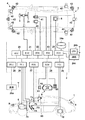
図1は、本発明の一実施形態に係る車両用制御装置のブロック図であり、車両1を制御する。図1において、車両1はその概略が平面図と側面図とで示されている。車両1は一例としてセダンタイプの四輪の乗用車である。
<First Embodiment>
[Vehicle configuration]
FIG. 1 is a block diagram of a vehicle control device according to an embodiment of the present invention, and controls the vehicle 1. In FIG. 1, the outline of the vehicle 1 is shown in a plan view and a side view. Vehicle 1 is, for example, a sedan-type four-wheeled passenger car.
図1の制御装置は、制御システム2を含む。制御システム2は車内ネットワークにより通信可能に接続された複数のECU20〜29を含む。各ECUは、CPUに代表されるプロセッサ、半導体メモリ等の記憶デバイス、外部デバイスとのインタフェース等を含むコンピュータとして機能する。記憶デバイスにはプロセッサが実行するプログラムやプロセッサが処理に使用するデータ等が格納される。各ECUはプロセッサ、記憶デバイスおよびインタフェース等を複数備えていてもよい。
The control device of FIG. 1 includes a
以下、各ECU20〜29が担当する機能等について説明する。なお、ECUの数や、担当する機能については適宜設計可能であり、本実施形態よりも細分化したり、あるいは、統合したりすることが可能である。
Hereinafter, the functions and the like that each
ECU20は、車両1の自動運転に関わる制御を実行する。自動運転においては、車両1の操舵と、加減速の少なくともいずれか一方を自動制御する。後述する制御例では、操舵と加減速の双方を自動制御する。 The ECU 20 executes control related to the automatic driving of the vehicle 1. In automatic driving, at least one of steering of the vehicle 1 and acceleration / deceleration is automatically controlled. In the control example described later, both steering and acceleration / deceleration are automatically controlled.
ECU21は、電動パワーステアリング装置3を制御する。電動パワーステアリング装置3は、ステアリングホイール31に対する運転者の運転操作(操舵操作)に応じて前輪を操舵する機構を含む。また、電動パワーステアリング装置3は操舵操作をアシストしたり、あるいは、前輪を自動操舵したりするための駆動力を発揮するモータや、操舵角を検知するセンサ等を含む。車両1の運転状態が自動運転の場合、ECU21は、ECU20からの指示に対応して電動パワーステアリング装置3を自動制御し、車両1の進行方向を制御する。また、ECU21は、車両1の停止時や操作主体の切り替え時などに舵角の維持制御を行う。
The ECU 21 controls the electric power steering device 3. The electric power steering device 3 includes a mechanism for steering the front wheels in response to a driver's driving operation (steering operation) with respect to the
ECU22および23は、車両の周囲状況を検知する検知ユニット41〜43の制御および検知結果の情報処理を行う。検知ユニット41は、車両1の前方を撮影するカメラであり(以下、カメラ41と表記する場合がある。)、本実施形態の場合、車両1のルーフ前部でフロントウィンドウの車室内側に取り付けられる。カメラ41が撮影した画像の解析により、物標の輪郭抽出や、道路上の車線の区画線(白線等)を抽出可能である。
The
検知ユニット42は、Light Detection and Ranging(LIDAR:ライダ)であり(以下、ライダ42と表記する場合がある)、車両1の周囲の物標を検知したり、物標との距離を測距したりする。本実施形態の場合、ライダ42は5つ設けられており、車両1の前部の各隅部に1つずつ、後部中央に1つ、後部各側方に1つずつ設けられている。検知ユニット43は、ミリ波レーダであり(以下、レーダ43と表記する場合がある)、車両1の周囲の物標を検知したり、物標との距離を測距したりする。本実施形態の場合、レーダ43は5つ設けられており、車両1の前部中央に1つ、前部各隅部に1つずつ、後部各隅部に一つずつ設けられている。さらに、図1には不図示であるが、車両1は、検知ユニット43と併せて、音波を用いるソナーを備えてよい。ソナーは、車両1の前方、後方、側方それぞれの物標を検知する位置に複数が設置され、例えば駐車支援制御にて利用可能である。
The
ECU22は、一方のカメラ41と、各ライダ42の制御および検知結果の情報処理を行う。ECU23は、他方のカメラ41と、各レーダ43の制御および検知結果の情報処理を行う。また、ECU22、23は、カメラ41にて取得した画像データに基づき、周辺画像を生成する。ここでの周辺画像としては、車両およびその周辺の平面視に相当する俯瞰画像や、車両およびその進行方向の周辺を情報から見た三次元画像に相当する鳥瞰画像などが挙げられる。車両の周囲状況を検知する装置を二組備えたことで、検知結果の信頼性を向上でき、また、カメラ、ライダ、レーダ、ソナーといった種類の異なる検知ユニットを備えたことで、車両の周辺環境の解析を多面的に行うことができる。
The ECU 22 controls one of the
ECU24は、ジャイロセンサ5、GPSセンサ24b、通信装置24cの制御および検知結果あるいは通信結果の情報処理を行う。ジャイロセンサ5は車両1の回転運動を検知する。ジャイロセンサ5の検知結果や、車輪速等により車両1の進路を判定することができる。GPSセンサ24bは、車両1の現在位置を検知する。通信装置24cは、地図情報や交通情報を提供するサーバと無線通信を行い、これらの情報を取得する。ECU24は、記憶デバイスに構築された地図情報のデータベース24aにアクセス可能であり、ECU24は現在地から目的地へのルート探索等を行う。
The ECU 24 controls the
ECU25は、車車間通信用の通信装置25aを備える。通信装置25aは、周辺の他車両と無線通信を行い、車両間での情報交換を行う。
The
ECU26は、パワープラント6を制御する。パワープラント6は車両1の駆動輪を回転させる駆動力を出力する機構であり、例えば、エンジンと変速機とを含む。ECU26は、例えば、アクセルペダル7Aに設けた操作検知センサ7aにより検知した運転者の運転操作(アクセル操作あるいは加速操作)に対応してエンジンの出力を制御したり、車速センサ7cが検知した車速等の情報に基づいて変速機の変速段を切り替えたりする。変速機の変速段の数や種類は特に限定するものではない。例えば、シフトポジションとしては、パーキング(P)レンジ、リバース(R)レンジ、ニュートラル(N)レンジ、ドライブ(D)レンジなどが挙げられる。車両1の運転状態が手動運転の場合、シフトポジションは、シフトレバー(不図示)の操作により切り替えが行われる。車両1の運転状態が自動運転の場合、ECU26は、ECU20からの指示に対応してパワープラント6を自動制御し、車両1の加減速を制御する。
The
ECU27は、方向指示器8(ウィンカー)を含む灯火器(ヘッドライト、テールライト等)を制御する。図1の例の場合、方向指示器8は車両1の前部、ドアミラーおよび後部に設けられている。
The
ECU28は、入出力装置9の制御を行う。入出力装置9は運転者に対する情報の出力と、運転者からの情報の入力の受け付けを行う。音声出力装置91は運転者に対して音声(文言)により情報を報知する。表示装置92は運転者に対して画像の表示により情報を報知する。表示装置92は例えば運転席正面に配置され、インストルメントパネル等を構成する。なお、ここでは、音声と表示を例示したが振動や光により情報を報知してもよい。また、音声、表示、振動または光のうちの複数を組み合わせて情報を報知してもよい。更に、報知すべき情報のレベル(例えば緊急度)に応じて、組み合わせを異ならせたり、報知態様を異ならせたりしてもよい。
The
入力装置93は運転者が操作可能な位置に配置され、車両1に対する指示を行うスイッチ群であるが、音声入力装置も含まれてもよい。入力装置93を構成するスイッチ群の構成は、車両1の機能に応じて設定されてよい。また、本実施形態では、入力装置93として、ECU22、23により生成された各種画像を表示するタッチパネルディスプレイを備える。
The
ECU29は、ブレーキ装置10やパーキングブレーキ(不図示)を制御する。ブレーキ装置10は例えばディスクブレーキ装置であり、車両1の各車輪に設けられ、車輪の回転に抵抗を加えることで車両1を減速あるいは停止させる。ECU29は、例えば、ブレーキペダル7Bに設けた操作検知センサ7bにより検知した運転者の運転操作(ブレーキ操作)に対応してブレーキ装置10の作動を制御する。車両1の運転状態が自動運転の場合、ECU29は、ECU20からの指示に対応してブレーキ装置10を自動制御し、車両1の減速および停止を制御する。ブレーキ装置10やパーキングブレーキは車両1の停止状態を維持するために作動することもできる。また、パワープラント6の変速機がパーキングロック機構を備える場合、これを車両1の停止状態を維持するために作動することもできる。
The
車両1は、車内の状態を検出する車内検出手段50を更に備える。ここでは、車内検出手段50として、撮像部としてのカメラや、重量センサ、温度検知センサなどにより構成され、その種類は特に限定するものではない。なお、車内検出手段50は、車両1に設けられた座席ごとに設けられてもよいし、車内全体を俯瞰および監視可能なように単一の構成にて設けられてもよい。 The vehicle 1 further includes an in-vehicle detecting means 50 for detecting an in-vehicle condition. Here, the vehicle interior detection means 50 includes a camera as an imaging unit, a weight sensor, a temperature detection sensor, and the like, and the type thereof is not particularly limited. The vehicle interior detection means 50 may be provided for each seat provided in the vehicle 1, or may be provided in a single configuration so that the entire interior of the vehicle can be overlooked and monitored.
[制御機能の例]
本実施形態に係る車両1の制御機能は、車両1の駆動、制動、操舵の制御に関わる走行関連機能と、運転者に対する情報の報知に関わる報知機能と、を含む。
[Example of control function]
The control function of the vehicle 1 according to the present embodiment includes a travel-related function related to control of driving, braking, and steering of the vehicle 1, and a notification function related to information notification to the driver.
走行関連機能としては、例えば、車線維持制御、車線逸脱抑制制御(路外逸脱抑制制御)、車線変更制御、前走車追従制御、衝突軽減ブレーキ制御、誤発進抑制制御、駐車支援制御を挙げることができる。報知機能としては、隣接車両報知制御、前走車発進報知制御、周辺物標報知制御を挙げることができる。また、報知機能は、音声、画像、映像などにより行われてよく、またこれらを組み合わせて行われてよい。 Examples of driving-related functions include lane keeping control, lane deviation suppression control (outside deviation suppression control), lane change control, preceding vehicle tracking control, collision mitigation braking control, false start suppression control, and parking support control. Can be done. Examples of the notification function include adjacent vehicle notification control, preceding vehicle start notification control, and peripheral target notification control. Further, the notification function may be performed by voice, an image, a video, or the like, or may be performed by combining these.
車線維持制御とは、車線に対する車両の位置の制御の一つであり、車線内に設定した走行軌道上で車両を自動的に(運転者の運転操作によらずに)走行させる制御である。車線逸脱抑制制御とは、車線に対する車両の位置の制御の一つであり、白線または中央分離帯を検知し、車両が線を超えないように自動的に操舵を行うものである。車線逸脱抑制制御と車線維持制御とはこのように機能が異なっている。 The lane keeping control is one of the control of the position of the vehicle with respect to the lane, and is the control for automatically driving the vehicle (regardless of the driving operation of the driver) on the traveling track set in the lane. The lane deviation suppression control is one of the control of the position of the vehicle with respect to the lane, and detects the white line or the median strip and automatically steers the vehicle so as not to cross the lane. Lane deviation suppression control and lane keeping control have different functions in this way.
車線変更制御とは、車両が走行中の車線から隣接車線へ車両を自動的に移動させる制御である。前走車追従制御とは、自車両の前方を走行する他車両に自動的に追従する制御である。衝突軽減ブレーキ制御とは、車両の前方の障害物との衝突可能性が高まった場合に、自動的に制動して衝突回避を支援する制御である。誤発進抑制制御は、車両の停止状態で運転者による加速操作が所定量以上の場合に、車両の加速を制限する制御であり、急発進を抑制する。 Lane change control is a control that automatically moves a vehicle from the lane in which the vehicle is traveling to an adjacent lane. The preceding vehicle tracking control is a control that automatically follows another vehicle traveling in front of the own vehicle. Collision mitigation braking control is a control that automatically brakes to support collision avoidance when the possibility of collision with an obstacle in front of the vehicle increases. The erroneous start suppression control is a control that limits the acceleration of the vehicle when the acceleration operation by the driver is a predetermined amount or more while the vehicle is stopped, and suppresses a sudden start.
駐車支援制御とは、指定された領域(停車位置)に対して、移動経路を特定し、車両1を自動的に移動させ停止状態とする制御である。本実施形態では、駐車支援制御として、走行している位置から駐車位置へ入庫する入庫制御と、駐車位置から走行可能な位置へ出庫する出庫制御の両方を対象として説明を行う。 The parking support control is a control that specifies a movement route for a designated area (stop position) and automatically moves the vehicle 1 to a stopped state. In the present embodiment, as the parking support control, both the warehousing control for entering the parking position from the traveling position and the warehousing control for leaving the parking position from the parking position to the travelable position will be described.
隣接車両報知制御とは、自車両の走行車線に隣接する隣接車線を走行する他車両の存在を運転者に報知する制御であり、例えば、自車両の側方、後方を走行する他車両の存在を報知する。前走車発進報知制御とは、自車両およびその前方の他車両が停止状態にあり、前方の他車両が発進したことを報知する制御である。周辺物標報知制御とは、自車両の周辺において、物標を検知した際に行われる報知制御である。ここでの検知範囲は、自車両の進行方向や、その時点での制御内容に応じて自車両が位置しようとする(移動しようとする)と想定される範囲に存在する物標を対象としてよい。これらの報知は上述した車内報知デバイスにより行うことができる。 The adjacent vehicle notification control is a control for notifying the driver of the existence of another vehicle traveling in the adjacent lane adjacent to the traveling lane of the own vehicle. Is notified. The preceding vehicle start notification control is a control for notifying that the own vehicle and the other vehicle in front of the own vehicle are in a stopped state and the other vehicle in front of the vehicle has started. Peripheral target notification control is notification control performed when a target is detected in the vicinity of the own vehicle. The detection range here may target a target existing in a range where the own vehicle is expected to be positioned (or to move) according to the traveling direction of the own vehicle and the control content at that time. .. These notifications can be performed by the above-mentioned in-vehicle notification device.
[表示例]
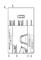
図2は、本実施形態に係る車両1が備える入力装置93に含まれるタッチパネルディスプレイにて表示される画面の構成例を示す。本実施形態では、カメラ41にて撮影された画像に基づき、ECU22、23が生成する俯瞰画像および鳥瞰画像が表示される。
[Display example]
FIG. 2 shows a configuration example of a screen displayed on the touch panel display included in the
画面200において、領域201には、メッセージが表示される。領域202には、車両1を中心とした鳥瞰画像が表示される。領域202では、進行方向(前進、後退)に応じて表示される画像が切り替えられてよい。領域203には、メッセージの他、ユーザーによる操作を受け付けるためのボタンが設けられる。本実施形態では、領域203において、駐車支援を実行させるためのボタン204が設けられている。なお、自動駐車を実行させるためのボタン204は、タッチパネルディスプレイの他、入力装置93を構成するスイッチ群の1つとして設けられてもよい。領域205には、車両1を中心とした俯瞰画像が表示される。
On the
なお、以下の説明では、走行支援制御の例として、駐車支援制御を例に挙げて説明するが、これに限定するものではない。その他の走行支援制御として、車両1(システム)側が制御主体となって行動している場合に本願発明は適用可能である。また、以下に説明する走行支援制御の中で、停止状態の維持といった動作支援制御もまとめて走行支援制御と称する。 In the following description, parking support control will be described as an example of driving support control, but the present invention is not limited to this. As other driving support control, the present invention can be applied when the vehicle 1 (system) side acts as the control subject. In addition, among the driving support controls described below, motion support control such as maintaining a stopped state is also collectively referred to as driving support control.
[動作概要]
図3は、本実施形態に係る走行支援制御の一例として駐車支援制御を行っている際の動作概要を説明するための図である。図3(a)は、車両301が駐車場などにおいて、検知ユニット41〜43による車両の周辺の検知結果に基づいて駐車位置を認識し、運転者の指示により入庫制御を開始した状態を示す。図3(a)の矢印は、入庫制御における車両1の経路を示し、これは、制御システム2により算出される。また、領域303は、入庫制御を行う際に車両301が切り返しを行う位置を示す。
[Outline of operation]
FIG. 3 is a diagram for explaining an outline of operation when parking support control is performed as an example of driving support control according to the present embodiment. FIG. 3A shows a state in which the
図3(b)は、図3(a)に示した状態から切り返し位置である領域303に移動した状態を示す。続いて、車両311は、バックにて駐車領域312への進行を開始する。このとき、移動物体である人物313と人物314がそれぞれ白抜き矢印方向に移動しているものとする。人物313がより車両311に近い位置に存在し、また、車両311の進行方向に位置する。車両311は、人物313および人物314の存在を検知ユニット41〜43の検知結果に基づき認識しているものとするが、ここでは、より近い人物313の存在により、進行を停止する。
FIG. 3B shows a state in which the state shown in FIG. 3A has been moved to the
その後、車両311は、停止状態となってから所定の時間が経過した後、進行を再開する。進行を再開した後、進行方向に再度何らかの障害物を検知した場合には、停止状態へ移行することとなる。つまり、駐車支援制御を行っている最中に、動作に対する何らかの障害物を複数検知した場合には、最初の検知に起因して停止を行い、その時点から所定の時間が経過後に、運転者の操作に拠らず再度駐車支援制御を再開するような構成とする。
After that, the
なお、車両311は、人物313の検知に起因して停止した停止状態(1回目の停止状態)と、その後、駐車支援制御を再開して再度何らかの障害物を検知して停止した停止状態(2回目の停止状態)とは、異なる制御にて停止状態を行ってよい。例えば、1回目の停止状態は、駐車支援制御における切り返し制御時の停止時間と障害物検知による停止時間との両方を考慮した停止制御であってよい。一方、2回目(さらにはそれ以降)の停止状態は、通常の衝突回避のための制動制御により行われてよい。更に、2回目(さらにはそれ以降)の停止状態は、搭乗者(例えば、運転者)が周辺監視を行っていることを前提とした制動制御により実行されてよい。具体的には、車両を停止する際に用いられる車両と障害物との距離や衝突の目安となる時間に対する閾値を、搭乗者が周辺監視を行っているものとして、小さくするように制御してもよい。
The
図3(b)の例の場合、車両311が人物313を検知したことに応じて停止状態となった場合、それから一定時間(停止時間)が経過後に自律的に駐車支援制御による進行が開始される。ここでの所定の時間とは、例えば、3秒や5秒などであってよい。このとき、再度周辺にて障害物(例えば、人物314)が検知された場合には、停止状態へと遷移する。しかしながら、人物313を検知してから一定時間内に(停止中に)人物314を検知したとしても停止時間を累積させる制御は行わない。なお、上述したように、1回目の停止状態における停止時間と、2回目(さらにはそれ以降)における停止時間とは、異なるように制御されてよい。
In the case of the example of FIG. 3B, when the
[処理フロー]
図4は、本実施形態に係る走行支援制御の際に行われる処理のフローチャートである。本処理フローは、例えば、車両1が備える各ECUが連携して処理を行うものとし、ここでは説明を簡略化するために、処理主体を走行支援システムとして動作する制御システム2として包括的に示す。本処理フローは、上述したような各種走行支援制御のいずれかが行われている際に実行される処理である。
[Processing flow]
FIG. 4 is a flowchart of processing performed during the driving support control according to the present embodiment. In this processing flow, for example, it is assumed that each ECU included in the vehicle 1 performs processing in cooperation with each other, and here, in order to simplify the explanation, the processing subject is comprehensively shown as a
S401にて、制御システム2は、検知ユニット41〜43により車両1の周辺監視を開始する。なお、周辺監視は、この構成以前から開始されていてもよい。また、実施する走行支援制御の内容に応じて、周辺監視にて利用する検知ユニットの種類や数、部位などが変化してよい。また、本実施形態において、走行支援制御が行われている際には運転者などによる周辺監視が行われているものとする。
In S401, the
S402にて、制御システム2は、走行支援制御を開始する。ここで開始される走行支援制御は運転者などの指示に基づき開始されるものとする。本実施形態では、駐車支援制御を例に挙げて説明する。
At S402, the
S403にて、制御システム2は、検知ユニット41〜43の検知結果により車両1の周辺において、走行支援制御の障害物となりうる物標を検知したか否かを判定する。障害物としては、例えば、図3にて示したような人の他、他車両(自動車や二輪車、自転車などを含む)や動物などの移動物体が挙げられる。障害物を検知した場合(S403にてYES)S406へ進み、検知していない場合(S403にてNO)S404へ進む。
In S403, the
S404にて、制御システム2は、走行支援制御が完了したか否かを判定する。例えば、走行支援制御が駐車支援制御である場合には、車両1が駐車位置に到達し、停止状態となった場合に完了したと判定される。走行支援制御が完了した場合(S404にてYES)S405へ進み、完了していない場合(S404にてNO)S403へ戻り、走行支援制御を継続する。
In S404, the
S405にて、制御システム2は、走行支援制御が完了した旨を通知する。ここでの通知方法としては、例えば、入力装置93に含まれるタッチパネルディスプレイにて表示してもよいし、音声などにより通知してもよい。そして、本処理フローを終了する。
In S405, the
S406にて、制御システム2は、検知した障害物に関する情報を運転者に報知する。ここでの報知内容については、図5を用いて後述する。
At S406, the
S407にて、制御システム2は、走行支援制御を中断し、停止状態に移行する。このとき、制御システム2は、操舵に関しては、その中断時点の状態を維持するように制御する。また、走行支援制御を中断した際の直前の制御状態の情報を保持していてもよい。また、ここでの停止状態では移動(加減速制御)は中断するものの、走行支援制御が再開した場合の動作を考慮して操舵制御は継続して実行可能であってよい。
At S407, the
S408にて、制御システム2は、S407にて停止状態に移行してから一定時間が経過したか否かを判定する。ここでの一定時間は予め定義されているものとし、例えば、3秒や5秒であってよい。一定時間が経過した場合は(S408にてYES)S409へ進み、経過していない場合は(S408にてNO)経過するまで待機する。なお、ここでは停止状態に移行したタイミングを計時の起点としたが、これに限定するものではなく、例えば、障害物を検知したタイミングを計時の起点としてもよい。また、停止制御が行われている際には、走行支援制御を再開するまでの残り時間を運転者に通知するような構成であってもよい。
In S408, the
S409にて、制御システム2は、停止状態を解除し、走行支援制御が再開可能な状態に移行する。
In S409, the
S410にて、制御システム2は、走行支援制御を再開させる。そして、S403へ戻り、走行支援制御を継続する。
At S410, the
[検知範囲例]
図5は、図4に示す処理が行われている際の、検知ユニットにより検知する範囲と車両1のシフトポジションとの関係を示す。本実施形態に係る車両1は、様々な走行支援制御を行うことが可能であり、その内容に応じてシフトポジションが切り替えられる。シフトポジションが切り替わることにより、進行方向や制御状態が切り替わるため、本実施形態では、シフトポジションに応じて検知ユニットによる検知方向を切り替える。つまり、対応する検知ユニットによる検知結果に基づき、図4のS403の障害物の検知判定が行われる。なお、上述したように本実施形態に係る車両1は、検知ユニットとして、カメラ、ライダ、レーダ、ソナーなどを備える。ここでは、少なくともカメラによる周辺検知を行うものとするが、他の検知ユニットを組み合わせて用いてよい。
[Detection range example]
FIG. 5 shows the relationship between the range detected by the detection unit and the shift position of the vehicle 1 when the process shown in FIG. 4 is being performed. The vehicle 1 according to the present embodiment can perform various driving support controls, and the shift position can be switched according to the contents thereof. Since the traveling direction and the control state are switched by switching the shift position, in the present embodiment, the detection direction by the detection unit is switched according to the shift position. That is, the obstacle detection determination in S403 of FIG. 4 is performed based on the detection result by the corresponding detection unit. As described above, the vehicle 1 according to the present embodiment includes a camera, a rider, a radar, a sonar, and the like as a detection unit. Here, at least peripheral detection by a camera is performed, but other detection units may be used in combination.
シフトポジションがドライブレンジであって、車両1が走行中である場合には、前方の監視を行う検知ユニットによる検知結果に基づいて、移動物体(障害物)の検知判定を行う。また、シフトポジションがドライブレンジであって、車両1が停車中である場合には、側方の監視を行う検知ユニットによる検知結果に基づいて、移動物体(障害物)の検知判定を行う。 When the shift position is the drive range and the vehicle 1 is traveling, the detection determination of a moving object (obstacle) is performed based on the detection result by the detection unit that monitors the front. Further, when the shift position is the drive range and the vehicle 1 is stopped, the detection determination of the moving object (obstacle) is performed based on the detection result by the detection unit that monitors the side.
シフトポジションがパーキングレンジもしくはニュートラルレンジである場合は、車両1は移動しないため、周辺監視は不要となる。 When the shift position is in the parking range or the neutral range, the vehicle 1 does not move, so peripheral monitoring becomes unnecessary.
シフトポジションがリバースレンジであって、車両1が走行中である場合には、後方の監視を行う検知ユニットによる検知結果に基づいて、移動物体(障害物)の検知判定を行う。また、シフトポジションがリバースレンジであって、車両1が停車中である場合には、側方の監視を行う検知ユニットによる検知結果に基づいて、移動物体(障害物)の検知判定を行う。 When the shift position is in the reverse range and the vehicle 1 is traveling, the detection determination of a moving object (obstacle) is performed based on the detection result by the detection unit that monitors the rear. Further, when the shift position is in the reverse range and the vehicle 1 is stopped, the detection determination of the moving object (obstacle) is performed based on the detection result by the detection unit that monitors the side.
[報知例]
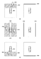
図6、図7は、図4に示す処理が行われている際に車両1の周辺にて移動物体を検知した場合の報知例を説明するための図である。ここでは、図2に示した画面200において、領域205を利用した報知方法について説明する。
[Notification example]
6 and 7 are diagrams for explaining an example of notification when a moving object is detected in the vicinity of the vehicle 1 while the process shown in FIG. 4 is being performed. Here, a notification method using the
図6(a)は、車両601の前方を検知ユニットにて監視している際に、検知領域602にて、移動物体603を検知した状況を示す。この場合、タッチパネルディスプレイ上にて検知方向を示すアイコン604が表示される。
FIG. 6A shows a situation in which a moving
図6(b)は、車両611の側方を検知ユニットにて監視している際に、検知領域612にて、移動物体613、614を検知した状況を示す。この場合、タッチパネルディスプレイ上にて検知方向を示すアイコン615が表示される。
FIG. 6B shows a situation in which moving
図6(c)は、車両621の後方を検知ユニットにて監視している際に、検知領域622にて、移動物体623を検知した状況を示す。この場合、タッチパネルディスプレイ上にて検知方向を示すアイコン624が表示される。
FIG. 6C shows a situation in which a moving
図7(a)は、車両701の周辺を検知ユニットにて監視している際に、前方および側方の領域をまたいで移動する移動物体703を検知した状態を示す。この場合、タッチパネルディスプレイ上にて前方および側方を示すアイコン704が表示される。
FIG. 7A shows a state in which a moving
図7(b)は、車両711の周辺を検知ユニットにて監視している際に、後方および側方の領域をまたいで移動する移動物体713を検知した状態を示す。この場合、タッチパネルディスプレイ上にて前方および側方を示すアイコン714が表示される。
FIG. 7B shows a state in which a moving
なお、図6および図7にて報知に用いられるアイコンは線状の表示を用いたがこれに限定するものではない。例えば、検知領域全体を示すような表示領域であってもよい。また、アイコンは、点滅や任意の色などの強調表示により運転者に明示するような構成であってもよい。また、音声などを併せて報知してもよい。 The icons used for notification in FIGS. 6 and 7 are linear displays, but the icons are not limited to these. For example, it may be a display area that shows the entire detection area. Further, the icon may be configured to be clearly shown to the driver by blinking or highlighting an arbitrary color or the like. In addition, voice or the like may also be notified.
本実施形態において、図6および図7にて示したアイコンによる報知は、図4のS4006にて行われる。また、S408にて一定時間が経過したと判定されるまで、検知した移動物体の方向に対応するアイコンは表示され続ける。なお、図4のS407〜S409の車両1が停止状態にある間に移動物体の検知方向が変化した場合には、その変化に応じてアイコンの表示を切り替えてもよい。この場合、当初検知した方向のアイコンは継続して表示し続けてもよい。 In the present embodiment, the notification by the icon shown in FIGS. 6 and 7 is performed in S4006 of FIG. Further, the icon corresponding to the direction of the detected moving object continues to be displayed until it is determined in S408 that a certain time has elapsed. If the detection direction of the moving object changes while the vehicle 1 of S407 to S409 of FIG. 4 is in the stopped state, the display of the icon may be switched according to the change. In this case, the icon in the initially detected direction may be continuously displayed.
また、図6および図7にて示した報知は、走行支援制御を行う際に表示するものであり、走行支援制御を行わずに車両上方視を表示するのみの場合には報知しなくても良い。例えば、走行支援制御のうちの駐車支援制御を行っている際には、図6および図7に示すような報知制御を行う。一方、走行支援制御を行わずに車両上方視を表示するのみの場合には、図6および図7に示すような報知制御を行わない構成であってよい。 Further, the notifications shown in FIGS. 6 and 7 are displayed when the driving support control is performed, and the notification is not required when only the vehicle upward view is displayed without the driving support control. good. For example, when the parking support control is performed among the running support controls, the notification control as shown in FIGS. 6 and 7 is performed. On the other hand, in the case where only the vehicle upward view is displayed without performing the traveling support control, the notification control as shown in FIGS. 6 and 7 may not be performed.
具体的には、タッチパネルディスプレイにおいて、走行支援制御の内容に応じて俯瞰画像と鳥瞰画像が切り替えて表示される構成が挙げられる。このような構成において、俯瞰画像が表示されている場合には、図6や図7の報知を行い、鳥瞰画像が表示されている場合には報知を行わないような構成であってもよい。 Specifically, the touch panel display may be configured to switch between a bird's-eye view image and a bird's-eye view image according to the content of the driving support control. In such a configuration, when the bird's-eye view image is displayed, the notification of FIGS. 6 and 7 may be performed, and when the bird's-eye view image is displayed, the notification may not be performed.
また、上述した停止制御は、所定の状況においてのみ実行するような構成であってもよい。例えば、図3にて示したような駐車支援制御の入庫動作において、入庫の動作開始時や切り返しが行われる最中に実行するような構成であってよい。具体的には、図3(a)や図3(b)に示すように、入庫の動作開始時や、切り返し動作時において、車両311は一旦、停止動作を行う。この場合、所定の停止時間が設けられる。この停止状態において、周辺にて障害物を検知した場合には、入庫動作開始時や切り返しによる所定の停止時間に加え、障害物を検知したことによる所定の時間(例えば、3秒)の間、停止した上で、移動を開始/再開するような構成であってよい。
Further, the above-mentioned stop control may be configured to be executed only in a predetermined situation. For example, in the parking support control warehousing operation as shown in FIG. 3, the warehousing operation may be executed at the start of the warehousing operation or during the turning back. Specifically, as shown in FIGS. 3 (a) and 3 (b), the
以上、本実施形態により、走行支援制御の動作中に移動障害物を検出した後の停車状態からシステム側での自律的な運転支援制御の動作の再開が可能となる。また、最初に検知した障害物に基づいて停止時間が規定されるため、必要以上の待ち時間が発生せず、車両の搭乗者に対する待ちのわずらわしさが低減される。更には、障害物としての移動物体を検知した際に適切に運転者に報知することが可能となり、運転者に検知した障害物に対する回避操作の促しを行うことが可能となる。 As described above, according to the present embodiment, it is possible to restart the operation of the autonomous driving support control on the system side from the stopped state after detecting the moving obstacle during the operation of the driving support control. Further, since the stop time is defined based on the obstacle detected first, the waiting time longer than necessary does not occur, and the troublesome waiting for the passengers of the vehicle is reduced. Further, when a moving object as an obstacle is detected, the driver can be appropriately notified, and the driver can be urged to perform an avoidance operation on the detected obstacle.
<実施形態のまとめ>
1.上記実施形態の走行支援システムは、車両(例えば、1)の走行支援システム(例えば、2)であって、
前記車両の周辺の情報を検出する検出手段(例えば、41〜43)と、
前記検出手段にて検出された情報に基づいて走行支援制御を行う制御手段(例えば、2)と
を有し、
前記制御手段は、前記走行支援制御を行っている際に、前記検出手段により検出された物標に起因して移動を停止した場合、当該停止を開始してから所定の時間の経過後に前記移動を再開させる。
<Summary of Embodiment>
1. 1. The traveling support system of the above embodiment is a traveling support system (for example, 2) of a vehicle (for example, 1).
A detection means (for example, 41 to 43) for detecting information around the vehicle, and
It has a control means (for example, 2) that performs driving support control based on the information detected by the detection means.
When the control means stops the movement due to the target detected by the detection means during the running support control, the movement is performed after a predetermined time has elapsed from the start of the stop. To resume.
この実施形態によれば、走行支援制御の動作中に移動障害物を検出した後の停車状態からシステム側で運転支援制御の動作の再開が可能となる。また、最初に検知した障害物に基づいて停止時間が規定されるため、必要以上の待ち時間が発生せず、車両の搭乗者に対する待ちのわずらわしさが低減される。 According to this embodiment, the operation of the driving support control can be restarted on the system side from the stopped state after detecting a moving obstacle during the operation of the driving support control. Further, since the stop time is defined based on the obstacle detected first, the waiting time longer than necessary does not occur, and the troublesome waiting for the passengers of the vehicle is reduced.
2.上記実施形態では、前記制御手段は、前記停止を行っている間に、前記検出手段により異なる物標が検出された場合でも、前記停止を開始してから前記所定の時間の経過後に前記移動を再開させる。 2. In the above embodiment, even if a different target is detected by the detection means while the stop is being performed, the control means performs the movement after the elapse of the predetermined time from the start of the stop. Resume.
この実施形態によれば、最初に検知した障害物に基づいて停止時間が規定されるため、必要以上の待ち時間が発生せず、車両の搭乗者に対する待ちのわずらわしさが低減される。 According to this embodiment, since the stop time is defined based on the obstacle detected first, the waiting time longer than necessary does not occur, and the annoyance of waiting for the passengers of the vehicle is reduced.
3.上記実施形態では、前記制御手段は、前記移動が再開された後に前記検出手段により物標が検出された場合、再度、移動を停止させる。 3. 3. In the above embodiment, the control means stops the movement again when the target is detected by the detection means after the movement is restarted.
この実施形態によれば、停止状態から移動を再開した場合でも、再度の停止が可能となる。 According to this embodiment, even when the movement is restarted from the stopped state, the movement can be stopped again.
4.上記実施形態では、前記制御手段は、前記走行支援制御において行われる停止動作の最中に、前記検出手段により物標が検出された場合、前記停止動作における停止時間に加え、前記所定の時間が経過した後、前記走行支援制御による移動を再開させる。 4. In the above embodiment, when the target is detected by the detection means during the stop operation performed in the travel support control, the control means has the predetermined time in addition to the stop time in the stop operation. After that, the movement by the traveling support control is restarted.
この実施形態によれば、走行支援制御において行われる停止動作の停止時間を考慮して、所定時間の停止状態の継続が行われ、運転者に対して周辺に存在する障害物の気づきを促すことができる。 According to this embodiment, the stop state is continued for a predetermined time in consideration of the stop time of the stop operation performed in the driving support control, and the driver is urged to notice the obstacles existing in the vicinity. Can be done.
5.上記実施形態では、前記走行支援制御は、駐車支援制御であり、
前記制御手段は、前記駐車支援制御における動作開始時または切り返し動作時に、前記検出手段により物標が検出された場合、前記動作開始時または切り返し動作時における停止時間に加え、前記所定の時間が経過した後、前記駐車支援制御による移動を開始させる。
5. In the above embodiment, the traveling support control is a parking support control.
When a target is detected by the detecting means at the time of starting the operation or at the time of turning back in the parking support control, the control means elapses the predetermined time in addition to the stop time at the time of starting the operation or at the time of turning back. After that, the movement by the parking support control is started.
この実施形態によれば、駐車支援制御において行われる停止動作の停止時間を考慮して、所定時間の停止状態の継続が行われ、運転者に対して周辺に存在する障害物の気づきを促すことができる。 According to this embodiment, in consideration of the stop time of the stop operation performed in the parking support control, the stop state is continued for a predetermined time, and the driver is urged to notice the obstacles existing in the vicinity. Can be done.
6.上記実施形態では、前記制御手段は、前記検出手段により検出された物標に起因した停止を開始してから前記移動を再開させるまでの間、操舵制御は実行可能とする。 6. In the above embodiment, the control means enables steering control to be executed from the start of the stop caused by the target detected by the detection means to the restart of the movement.
この実施形態によれば、停止状態を維持している際に操舵制御を許可することで、停止状態が解除された後の動作にスムーズに移行することが可能となる。 According to this embodiment, by permitting steering control while the stopped state is maintained, it is possible to smoothly shift to the operation after the stopped state is released.
7.上記実施形態では、前記検出手段にて物標を検出した際に報知する報知手段を更に有し、
複数の前記検出手段が備えられ、
前記報知手段は、前記物標を検知した検出手段に対応して報知を行う。
7. In the above embodiment, the detection means further includes a notification means for notifying when a target is detected.
A plurality of the detection means are provided, and the detection means is provided.
The notification means performs notification corresponding to the detection means that has detected the target.
この実施形態によれば、障害物が検出された際に、適切に報知することができる。 According to this embodiment, when an obstacle is detected, it can be appropriately notified.
8.上記実施形態では、前記複数の検出手段それぞれに対応した表示領域を含んで構成される表示手段を更に有し、
前記報知手段は、前記物標を検知した検出手段に対応する表示領域を強調表示するように前記表示手段に表示させる。
8. In the above embodiment, the display means further includes a display area corresponding to each of the plurality of detection means.
The notification means causes the display means to display a display area corresponding to the detection means that has detected the target.
この実施形態によれば、障害物が検出された際に、当該障害物を検出した検出手段に応じた適切な報知を行うことができる。 According to this embodiment, when an obstacle is detected, appropriate notification can be performed according to the detecting means for detecting the obstacle.
9.上記実施形態では、前記表示手段は、前記走行支援制御の作動によらず複数の検出手段それぞれに対応した表示領域を表示可能であり、
前記報知手段は、前記走行支援制御が行われているか否かに応じて、前記強調表示を行うか否かを切り替える。
9. In the above embodiment, the display means can display a display area corresponding to each of the plurality of detection means regardless of the operation of the travel support control.
The notification means switches whether or not to perform the highlighting depending on whether or not the traveling support control is performed.
この実施形態によれば、走行支援制御が行われているか否かに応じて報知を切り替えるため、運転者が報知によるわずらわしさを感じる程度を低減することができる。 According to this embodiment, since the notification is switched depending on whether or not the driving support control is performed, it is possible to reduce the degree to which the driver feels annoyance due to the notification.
10.上記実施形態の走行支援システムの制御方法は、車両(例えば、1)の走行支援システム(例えば、2)の制御方法であって、
前記車両の周辺の情報を検出手段(例えば、41〜43)にて検出する検出工程と、
前記検出手段にて検出された情報に基づいて走行支援制御を行う制御工程と
を有し、
前記制御工程において、前記走行支援制御を行っている際に、前記検出手段により検出された物標に起因して移動を停止した場合、当該停止を開始してから所定の時間の経過後に前記移動を再開させる。
10. The control method of the travel support system of the above embodiment is a control method of the travel support system (for example, 2) of the vehicle (for example, 1).
A detection step of detecting information around the vehicle by a detection means (for example, 41 to 43).
It has a control process that performs driving support control based on the information detected by the detection means.
In the control step, when the movement is stopped due to the target detected by the detection means during the running support control, the movement is performed after a predetermined time has elapsed from the start of the stop. To resume.
この実施形態によれば、走行支援制御の動作中に移動障害物を検出した後の停車状態からシステム側で運転支援制御の動作の再開が可能となる。また、最初に検知した障害物に基づいて停止時間が規定されるため、必要以上の待ち時間が発生せず、車両の搭乗者に対する待ちのわずらわしさが低減される。 According to this embodiment, the operation of the driving support control can be restarted on the system side from the stopped state after detecting a moving obstacle during the operation of the driving support control. Further, since the stop time is defined based on the obstacle detected first, the waiting time longer than necessary does not occur, and the troublesome waiting for the passengers of the vehicle is reduced.
本発明は上記実施の形態に制限されるものではなく、本発明の精神及び範囲から離脱することなく、様々な変更及び変形が可能である。 The present invention is not limited to the above embodiments, and various modifications and modifications can be made without departing from the spirit and scope of the present invention.
1:車両制御装置、1A:第1制御部、1B:第2制御部、20A:自動運転ECU、21A:環境認識ECU、21B:走行支援ECU、41A,41B:電動パワーステアリング装置、42A,42B:油圧装置、82:外界認識装置群、83:アクチュエータ群 1: Vehicle control device, 1A: 1st control unit, 1B: 2nd control unit, 20A: automatic driving ECU, 21A: environment recognition ECU, 21B: driving support ECU, 41A, 41B: electric power steering device, 42A, 42B : Hydraulic device, 82: External recognition device group, 83: Actuator group
Claims (9)
前記車両の周辺の情報を検出する検出手段と、
前記検出手段にて検出された情報に基づいて走行支援制御を行う制御手段と
を有し、
前記制御手段は、前記走行支援制御を行っている際に、前記検出手段により検出された物標に起因して移動を停止した場合、当該停止を行っている間に、前記検出手段により異なる物標が検出された場合でも、前記停止を開始してから所定の時間の経過後に前記移動を再開させることを特徴とする走行支援システム。 It is a vehicle driving support system
A detection means for detecting information around the vehicle and
It has a control means that performs driving support control based on the information detected by the detection means.
When the control means stops moving due to the target detected by the detection means during the running support control, the control means differs depending on the detection means during the stop. A traveling support system characterized in that even when a mark is detected, the movement is restarted after a lapse of a predetermined time from the start of the stop.
前記制御手段は、前記駐車支援制御における動作開始時または切り返し動作時に、前記検出手段により物標が検出された場合、前記動作開始時または切り返し動作時における停止時間に加え、前記所定の時間が経過した後、前記駐車支援制御による移動を開始させることを特徴とする請求項1乃至3のいずれか一項に記載の走行支援システム。 The driving support control is a parking support control.
When a target is detected by the detection means at the time of starting the operation or at the time of turning back in the parking support control, the control means elapses the predetermined time in addition to the stop time at the time of starting the operation or at the time of turning back. The traveling support system according to any one of claims 1 to 3 , wherein the movement is started by the parking support control.
複数の前記検出手段が備えられ、
前記報知手段は、前記物標を検知した検出手段に対応して報知を行うことを特徴とする請求項1乃至5のいずれか一項に記載の走行支援システム。 Further, it has a notification means for notifying when a target is detected by the detection means.
A plurality of the detection means are provided, and the detection means is provided.
The traveling support system according to any one of claims 1 to 5 , wherein the notification means performs notification in response to the detection means that has detected the target.
前記報知手段は、前記物標を検知した検出手段に対応する表示領域を強調表示するように前記表示手段に表示させることを特徴とする請求項6に記載の走行支援システム。 Further having a display means configured to include a display area corresponding to each of the plurality of detection means.
The traveling support system according to claim 6 , wherein the notification means causes the display means to display a display area corresponding to the detection means that has detected the target so as to highlight the display area.
前記報知手段は、前記走行支援制御が行われているか否かに応じて、前記強調表示を行うか否かを切り替えることを特徴とする請求項7に記載の走行支援システム。 The display means can display a display area corresponding to each of the plurality of detection means regardless of the operation of the travel support control.
The travel support system according to claim 7 , wherein the notification means switches whether or not to perform the highlighting depending on whether or not the travel support control is performed.
前記車両の周辺の情報を検出手段にて検出する検出工程と、
前記検出手段にて検出された情報に基づいて走行支援制御を行う制御工程と
を有し、
前記制御工程において、前記走行支援制御を行っている際に、前記検出手段により検出された物標に起因して移動を停止した場合、当該停止を行っている間に、前記検出手段により異なる物標が検出された場合でも、前記停止を開始してから所定の時間の経過後に前記移動を再開させることを特徴とする走行支援システムの制御方法。 It is a control method of the vehicle driving support system.
A detection process for detecting information around the vehicle by a detection means, and
It has a control process that performs driving support control based on the information detected by the detection means.
In the control step, when the movement is stopped due to the target detected by the detection means during the running support control, an object different depending on the detection means during the stop. A control method of a traveling support system, characterized in that the movement is restarted after a lapse of a predetermined time from the start of the stop even when the mark is detected.
Priority Applications (3)
| Application Number | Priority Date | Filing Date | Title |
|---|---|---|---|
| JP2019225729A JP6962996B2 (en) | 2019-12-13 | 2019-12-13 | Driving support system and its control method |
| US17/099,889 US11613252B2 (en) | 2019-12-13 | 2020-11-17 | Driving assistance system and control method thereof |
| CN202011307336.4A CN112977451B (en) | 2019-12-13 | 2020-11-20 | Driving support system and control method thereof |
Applications Claiming Priority (1)
| Application Number | Priority Date | Filing Date | Title |
|---|---|---|---|
| JP2019225729A JP6962996B2 (en) | 2019-12-13 | 2019-12-13 | Driving support system and its control method |
Publications (2)
| Publication Number | Publication Date |
|---|---|
| JP2021094907A JP2021094907A (en) | 2021-06-24 |
| JP6962996B2 true JP6962996B2 (en) | 2021-11-05 |
Family
ID=76317424
Family Applications (1)
| Application Number | Title | Priority Date | Filing Date |
|---|---|---|---|
| JP2019225729A Active JP6962996B2 (en) | 2019-12-13 | 2019-12-13 | Driving support system and its control method |
Country Status (3)
| Country | Link |
|---|---|
| US (1) | US11613252B2 (en) |
| JP (1) | JP6962996B2 (en) |
| CN (1) | CN112977451B (en) |
Families Citing this family (2)
| Publication number | Priority date | Publication date | Assignee | Title |
|---|---|---|---|---|
| JP2022139186A (en) * | 2021-03-11 | 2022-09-26 | 本田技研工業株式会社 | Information processing apparatus and program |
| JP2023105462A (en) * | 2022-01-19 | 2023-07-31 | 株式会社豊田自動織機 | engine type industrial vehicle |
Family Cites Families (8)
| Publication number | Priority date | Publication date | Assignee | Title |
|---|---|---|---|---|
| JP5939130B2 (en) * | 2012-10-31 | 2016-06-22 | トヨタ自動車株式会社 | Driving assistance device |
| JP2015009646A (en) * | 2013-06-28 | 2015-01-19 | アルパイン株式会社 | Driving support device |
| JP6544121B2 (en) * | 2015-07-31 | 2019-07-17 | アイシン精機株式会社 | Parking assistance device |
| JP2018001962A (en) * | 2016-07-01 | 2018-01-11 | 本田技研工業株式会社 | Vehicle control device |
| JP6990020B2 (en) | 2016-11-28 | 2022-01-12 | 株式会社Subaru | Vehicle follow-up start control device |
| US11230284B2 (en) * | 2017-03-17 | 2022-01-25 | Hitachi Astemo, Ltd. | Driving assistance apparatus and driving assistance method |
| JP7040098B2 (en) * | 2018-02-15 | 2022-03-23 | トヨタ自動車株式会社 | Steering support device |
| JP7126362B2 (en) * | 2018-03-22 | 2022-08-26 | 日産自動車株式会社 | AUTOMATIC VEHICLE PARKING CONTROL METHOD AND PARKING CONTROL DEVICE |
-
2019
- 2019-12-13 JP JP2019225729A patent/JP6962996B2/en active Active
-
2020
- 2020-11-17 US US17/099,889 patent/US11613252B2/en active Active
- 2020-11-20 CN CN202011307336.4A patent/CN112977451B/en active Active
Also Published As
| Publication number | Publication date |
|---|---|
| CN112977451A (en) | 2021-06-18 |
| JP2021094907A (en) | 2021-06-24 |
| US11613252B2 (en) | 2023-03-28 |
| CN112977451B (en) | 2024-04-19 |
| US20210179082A1 (en) | 2021-06-17 |
Similar Documents
| Publication | Publication Date | Title |
|---|---|---|
| JP6966489B2 (en) | Vehicle control systems, vehicle control methods, and programs | |
| JP7445028B2 (en) | Vehicle control system, vehicle control method, and program | |
| JP6936325B2 (en) | Vehicles and their control devices and control methods | |
| WO2019142284A1 (en) | Vehicle control device | |
| US11449060B2 (en) | Vehicle, apparatus for controlling same, and control method therefor | |
| JP7055043B2 (en) | Vehicle control device and vehicle | |
| US20230415735A1 (en) | Driving support apparatus, control method of vehicle, and non-transitory computer-readable storage medium | |
| JP6970215B2 (en) | Vehicle control device, vehicle with it, and control method | |
| US11794725B2 (en) | Travel support system and control method thereof | |
| JP4961592B2 (en) | Vehicle travel support device | |
| US11634129B2 (en) | Travel control apparatus, vehicle, travel control method, and non-transitory computer-readable storage medium | |
| JP6962996B2 (en) | Driving support system and its control method | |
| US11654931B2 (en) | Driving assistance device and vehicle | |
| JP2019155957A (en) | Vehicular control device and vehicle | |
| JP2023112053A (en) | Image processing device | |
| JP7138133B2 (en) | VEHICLE CONTROL DEVICE, VEHICLE, OPERATING METHOD AND PROGRAM OF VEHICLE CONTROL DEVICE | |
| US12115975B2 (en) | Parking support system and control method thereof | |
| US20210179085A1 (en) | Parking support system and control method thereof | |
| US20240101112A1 (en) | Control device and control method for vehicle | |
| JP7504958B2 (en) | Vehicle control device and control method | |
| US20230249716A1 (en) | Vehicle, control device and control method therefor | |
| JP6596047B2 (en) | Vehicle control device, vehicle, and method |
Legal Events
| Date | Code | Title | Description |
|---|---|---|---|
| A621 | Written request for application examination |
Free format text: JAPANESE INTERMEDIATE CODE: A621 Effective date: 20200831 |
|
| RD02 | Notification of acceptance of power of attorney |
Free format text: JAPANESE INTERMEDIATE CODE: A7422 Effective date: 20210103 |
|
| A521 | Request for written amendment filed |
Free format text: JAPANESE INTERMEDIATE CODE: A523 Effective date: 20210125 |
|
| A131 | Notification of reasons for refusal |
Free format text: JAPANESE INTERMEDIATE CODE: A131 Effective date: 20210730 |
|
| A521 | Request for written amendment filed |
Free format text: JAPANESE INTERMEDIATE CODE: A523 Effective date: 20210916 |
|
| TRDD | Decision of grant or rejection written | ||
| A01 | Written decision to grant a patent or to grant a registration (utility model) |
Free format text: JAPANESE INTERMEDIATE CODE: A01 Effective date: 20211004 |
|
| A61 | First payment of annual fees (during grant procedure) |
Free format text: JAPANESE INTERMEDIATE CODE: A61 Effective date: 20211014 |
|
| R150 | Certificate of patent or registration of utility model |
Ref document number: 6962996 Country of ref document: JP Free format text: JAPANESE INTERMEDIATE CODE: R150 |