JP6962816B2 - Hydropower / Fluid Power Turbines and Their Manufacturing and Usage - Google Patents
Hydropower / Fluid Power Turbines and Their Manufacturing and Usage Download PDFInfo
- Publication number
- JP6962816B2 JP6962816B2 JP2017542866A JP2017542866A JP6962816B2 JP 6962816 B2 JP6962816 B2 JP 6962816B2 JP 2017542866 A JP2017542866 A JP 2017542866A JP 2017542866 A JP2017542866 A JP 2017542866A JP 6962816 B2 JP6962816 B2 JP 6962816B2
- Authority
- JP
- Japan
- Prior art keywords
- turbine
- rotor
- accelerator shroud
- water
- center hub
- Prior art date
- Legal status (The legal status is an assumption and is not a legal conclusion. Google has not performed a legal analysis and makes no representation as to the accuracy of the status listed.)
- Active
Links
- 239000012530 fluid Substances 0.000 title claims description 85
- 238000004519 manufacturing process Methods 0.000 title description 3
- XLYOFNOQVPJJNP-UHFFFAOYSA-N water Substances O XLYOFNOQVPJJNP-UHFFFAOYSA-N 0.000 claims description 166
- 238000013461 design Methods 0.000 claims description 106
- 238000000034 method Methods 0.000 claims description 27
- 230000001133 acceleration Effects 0.000 claims description 18
- 230000008859 change Effects 0.000 claims description 14
- 238000012360 testing method Methods 0.000 claims description 12
- 238000010248 power generation Methods 0.000 claims description 6
- 230000004044 response Effects 0.000 claims description 2
- 238000004804 winding Methods 0.000 claims description 2
- 238000011144 upstream manufacturing Methods 0.000 claims 1
- 238000012423 maintenance Methods 0.000 description 20
- 238000007667 floating Methods 0.000 description 17
- 230000000694 effects Effects 0.000 description 12
- 238000004458 analytical method Methods 0.000 description 11
- 230000001965 increasing effect Effects 0.000 description 11
- 238000009434 installation Methods 0.000 description 11
- 230000008901 benefit Effects 0.000 description 10
- 230000008439 repair process Effects 0.000 description 10
- 230000002457 bidirectional effect Effects 0.000 description 9
- 230000005611 electricity Effects 0.000 description 8
- 230000007717 exclusion Effects 0.000 description 8
- RYGMFSIKBFXOCR-UHFFFAOYSA-N Copper Chemical compound [Cu] RYGMFSIKBFXOCR-UHFFFAOYSA-N 0.000 description 7
- 238000000605 extraction Methods 0.000 description 7
- 239000002131 composite material Substances 0.000 description 6
- 238000012938 design process Methods 0.000 description 6
- 230000007246 mechanism Effects 0.000 description 6
- 239000007787 solid Substances 0.000 description 6
- 230000002195 synergetic effect Effects 0.000 description 6
- 150000001875 compounds Chemical class 0.000 description 5
- 229910052802 copper Inorganic materials 0.000 description 5
- 239000010949 copper Substances 0.000 description 5
- 238000005457 optimization Methods 0.000 description 5
- 230000036961 partial effect Effects 0.000 description 5
- 238000007493 shaping process Methods 0.000 description 5
- 230000002411 adverse Effects 0.000 description 4
- 230000005540 biological transmission Effects 0.000 description 4
- 238000005339 levitation Methods 0.000 description 4
- 229910052751 metal Inorganic materials 0.000 description 4
- 239000002184 metal Substances 0.000 description 4
- 230000009286 beneficial effect Effects 0.000 description 3
- 238000004364 calculation method Methods 0.000 description 3
- 238000004590 computer program Methods 0.000 description 3
- 238000010276 construction Methods 0.000 description 3
- 238000011161 development Methods 0.000 description 3
- 230000007613 environmental effect Effects 0.000 description 3
- 230000006872 improvement Effects 0.000 description 3
- 230000008569 process Effects 0.000 description 3
- 241000894007 species Species 0.000 description 3
- 241000196324 Embryophyta Species 0.000 description 2
- 230000003373 anti-fouling effect Effects 0.000 description 2
- 238000004140 cleaning Methods 0.000 description 2
- 238000000576 coating method Methods 0.000 description 2
- 239000011162 core material Substances 0.000 description 2
- 230000003247 decreasing effect Effects 0.000 description 2
- 238000005516 engineering process Methods 0.000 description 2
- 230000003993 interaction Effects 0.000 description 2
- 239000000463 material Substances 0.000 description 2
- 239000000203 mixture Substances 0.000 description 2
- 231100000252 nontoxic Toxicity 0.000 description 2
- 230000003000 nontoxic effect Effects 0.000 description 2
- 238000004088 simulation Methods 0.000 description 2
- 238000012546 transfer Methods 0.000 description 2
- 241000251468 Actinopterygii Species 0.000 description 1
- OKTJSMMVPCPJKN-UHFFFAOYSA-N Carbon Chemical compound [C] OKTJSMMVPCPJKN-UHFFFAOYSA-N 0.000 description 1
- 229920000049 Carbon (fiber) Polymers 0.000 description 1
- 241000283153 Cetacea Species 0.000 description 1
- 240000007058 Halophila ovalis Species 0.000 description 1
- 241000282806 Rhinoceros Species 0.000 description 1
- 229910000831 Steel Inorganic materials 0.000 description 1
- 241000270666 Testudines Species 0.000 description 1
- RTAQQCXQSZGOHL-UHFFFAOYSA-N Titanium Chemical compound [Ti] RTAQQCXQSZGOHL-UHFFFAOYSA-N 0.000 description 1
- 230000006978 adaptation Effects 0.000 description 1
- 229910052782 aluminium Inorganic materials 0.000 description 1
- XAGFODPZIPBFFR-UHFFFAOYSA-N aluminium Chemical compound [Al] XAGFODPZIPBFFR-UHFFFAOYSA-N 0.000 description 1
- 238000004873 anchoring Methods 0.000 description 1
- 229920006231 aramid fiber Polymers 0.000 description 1
- 230000001174 ascending effect Effects 0.000 description 1
- 230000015572 biosynthetic process Effects 0.000 description 1
- 239000004566 building material Substances 0.000 description 1
- 229910052799 carbon Inorganic materials 0.000 description 1
- 239000004917 carbon fiber Substances 0.000 description 1
- 239000003610 charcoal Substances 0.000 description 1
- 239000011248 coating agent Substances 0.000 description 1
- 230000002301 combined effect Effects 0.000 description 1
- 230000000052 comparative effect Effects 0.000 description 1
- 230000006835 compression Effects 0.000 description 1
- 238000007906 compression Methods 0.000 description 1
- 238000012790 confirmation Methods 0.000 description 1
- 125000004122 cyclic group Chemical group 0.000 description 1
- 230000007423 decrease Effects 0.000 description 1
- 238000009826 distribution Methods 0.000 description 1
- 230000009189 diving Effects 0.000 description 1
- 238000005553 drilling Methods 0.000 description 1
- 238000009429 electrical wiring Methods 0.000 description 1
- 230000005670 electromagnetic radiation Effects 0.000 description 1
- 230000008030 elimination Effects 0.000 description 1
- 238000003379 elimination reaction Methods 0.000 description 1
- 230000002708 enhancing effect Effects 0.000 description 1
- 239000000284 extract Substances 0.000 description 1
- 239000000835 fiber Substances 0.000 description 1
- 239000011152 fibreglass Substances 0.000 description 1
- 239000006260 foam Substances 0.000 description 1
- 239000003365 glass fiber Substances 0.000 description 1
- 230000007774 longterm Effects 0.000 description 1
- 238000005259 measurement Methods 0.000 description 1
- 229910001092 metal group alloy Inorganic materials 0.000 description 1
- VNWKTOKETHGBQD-UHFFFAOYSA-N methane Chemical compound C VNWKTOKETHGBQD-UHFFFAOYSA-N 0.000 description 1
- 230000009972 noncorrosive effect Effects 0.000 description 1
- 239000003973 paint Substances 0.000 description 1
- 230000000737 periodic effect Effects 0.000 description 1
- 229920000642 polymer Polymers 0.000 description 1
- 238000005381 potential energy Methods 0.000 description 1
- 238000012113 quantitative test Methods 0.000 description 1
- 230000002829 reductive effect Effects 0.000 description 1
- 239000011347 resin Substances 0.000 description 1
- 229920005989 resin Polymers 0.000 description 1
- 230000002441 reversible effect Effects 0.000 description 1
- 230000000630 rising effect Effects 0.000 description 1
- 230000001932 seasonal effect Effects 0.000 description 1
- 239000010959 steel Substances 0.000 description 1
- 230000009044 synergistic interaction Effects 0.000 description 1
- 229920002994 synthetic fiber Polymers 0.000 description 1
- 239000010936 titanium Substances 0.000 description 1
- 229910052719 titanium Inorganic materials 0.000 description 1
- 230000007704 transition Effects 0.000 description 1
- 230000001960 triggered effect Effects 0.000 description 1
- 238000009732 tufting Methods 0.000 description 1
- 230000005641 tunneling Effects 0.000 description 1
Images


Classifications
-
- F—MECHANICAL ENGINEERING; LIGHTING; HEATING; WEAPONS; BLASTING
- F03—MACHINES OR ENGINES FOR LIQUIDS; WIND, SPRING, OR WEIGHT MOTORS; PRODUCING MECHANICAL POWER OR A REACTIVE PROPULSIVE THRUST, NOT OTHERWISE PROVIDED FOR
- F03B—MACHINES OR ENGINES FOR LIQUIDS
- F03B11/00—Parts or details not provided for in, or of interest apart from, the preceding groups, e.g. wear-protection couplings, between turbine and generator
- F03B11/02—Casings
-
- F—MECHANICAL ENGINEERING; LIGHTING; HEATING; WEAPONS; BLASTING
- F03—MACHINES OR ENGINES FOR LIQUIDS; WIND, SPRING, OR WEIGHT MOTORS; PRODUCING MECHANICAL POWER OR A REACTIVE PROPULSIVE THRUST, NOT OTHERWISE PROVIDED FOR
- F03B—MACHINES OR ENGINES FOR LIQUIDS
- F03B17/00—Other machines or engines
- F03B17/06—Other machines or engines using liquid flow with predominantly kinetic energy conversion, e.g. of swinging-flap type, "run-of-river", "ultra-low head"
- F03B17/061—Other machines or engines using liquid flow with predominantly kinetic energy conversion, e.g. of swinging-flap type, "run-of-river", "ultra-low head" with rotation axis substantially in flow direction
-
- F—MECHANICAL ENGINEERING; LIGHTING; HEATING; WEAPONS; BLASTING
- F03—MACHINES OR ENGINES FOR LIQUIDS; WIND, SPRING, OR WEIGHT MOTORS; PRODUCING MECHANICAL POWER OR A REACTIVE PROPULSIVE THRUST, NOT OTHERWISE PROVIDED FOR
- F03B—MACHINES OR ENGINES FOR LIQUIDS
- F03B3/00—Machines or engines of reaction type; Parts or details peculiar thereto
- F03B3/04—Machines or engines of reaction type; Parts or details peculiar thereto with substantially axial flow throughout rotors, e.g. propeller turbines
-
- F—MECHANICAL ENGINEERING; LIGHTING; HEATING; WEAPONS; BLASTING
- F03—MACHINES OR ENGINES FOR LIQUIDS; WIND, SPRING, OR WEIGHT MOTORS; PRODUCING MECHANICAL POWER OR A REACTIVE PROPULSIVE THRUST, NOT OTHERWISE PROVIDED FOR
- F03B—MACHINES OR ENGINES FOR LIQUIDS
- F03B3/00—Machines or engines of reaction type; Parts or details peculiar thereto
- F03B3/12—Blades; Blade-carrying rotors
- F03B3/121—Blades, their form or construction
-
- F—MECHANICAL ENGINEERING; LIGHTING; HEATING; WEAPONS; BLASTING
- F03—MACHINES OR ENGINES FOR LIQUIDS; WIND, SPRING, OR WEIGHT MOTORS; PRODUCING MECHANICAL POWER OR A REACTIVE PROPULSIVE THRUST, NOT OTHERWISE PROVIDED FOR
- F03B—MACHINES OR ENGINES FOR LIQUIDS
- F03B3/00—Machines or engines of reaction type; Parts or details peculiar thereto
- F03B3/12—Blades; Blade-carrying rotors
- F03B3/126—Rotors for essentially axial flow, e.g. for propeller turbines
-
- F—MECHANICAL ENGINEERING; LIGHTING; HEATING; WEAPONS; BLASTING
- F03—MACHINES OR ENGINES FOR LIQUIDS; WIND, SPRING, OR WEIGHT MOTORS; PRODUCING MECHANICAL POWER OR A REACTIVE PROPULSIVE THRUST, NOT OTHERWISE PROVIDED FOR
- F03B—MACHINES OR ENGINES FOR LIQUIDS
- F03B3/00—Machines or engines of reaction type; Parts or details peculiar thereto
- F03B3/16—Stators
- F03B3/18—Stator blades; Guide conduits or vanes, e.g. adjustable
-
- H—ELECTRICITY
- H02—GENERATION; CONVERSION OR DISTRIBUTION OF ELECTRIC POWER
- H02K—DYNAMO-ELECTRIC MACHINES
- H02K7/00—Arrangements for handling mechanical energy structurally associated with dynamo-electric machines, e.g. structural association with mechanical driving motors or auxiliary dynamo-electric machines
- H02K7/18—Structural association of electric generators with mechanical driving motors, e.g. with turbines
-
- F—MECHANICAL ENGINEERING; LIGHTING; HEATING; WEAPONS; BLASTING
- F05—INDEXING SCHEMES RELATING TO ENGINES OR PUMPS IN VARIOUS SUBCLASSES OF CLASSES F01-F04
- F05B—INDEXING SCHEME RELATING TO WIND, SPRING, WEIGHT, INERTIA OR LIKE MOTORS, TO MACHINES OR ENGINES FOR LIQUIDS COVERED BY SUBCLASSES F03B, F03D AND F03G
- F05B2220/00—Application
- F05B2220/70—Application in combination with
- F05B2220/706—Application in combination with an electrical generator
- F05B2220/7068—Application in combination with an electrical generator equipped with permanent magnets
-
- F—MECHANICAL ENGINEERING; LIGHTING; HEATING; WEAPONS; BLASTING
- F05—INDEXING SCHEMES RELATING TO ENGINES OR PUMPS IN VARIOUS SUBCLASSES OF CLASSES F01-F04
- F05B—INDEXING SCHEME RELATING TO WIND, SPRING, WEIGHT, INERTIA OR LIKE MOTORS, TO MACHINES OR ENGINES FOR LIQUIDS COVERED BY SUBCLASSES F03B, F03D AND F03G
- F05B2230/00—Manufacture
- F05B2230/60—Assembly methods
- F05B2230/61—Assembly methods using auxiliary equipment for lifting or holding
- F05B2230/6102—Assembly methods using auxiliary equipment for lifting or holding carried on a floating platform
-
- F—MECHANICAL ENGINEERING; LIGHTING; HEATING; WEAPONS; BLASTING
- F05—INDEXING SCHEMES RELATING TO ENGINES OR PUMPS IN VARIOUS SUBCLASSES OF CLASSES F01-F04
- F05B—INDEXING SCHEME RELATING TO WIND, SPRING, WEIGHT, INERTIA OR LIKE MOTORS, TO MACHINES OR ENGINES FOR LIQUIDS COVERED BY SUBCLASSES F03B, F03D AND F03G
- F05B2230/00—Manufacture
- F05B2230/80—Repairing, retrofitting or upgrading methods
-
- F—MECHANICAL ENGINEERING; LIGHTING; HEATING; WEAPONS; BLASTING
- F05—INDEXING SCHEMES RELATING TO ENGINES OR PUMPS IN VARIOUS SUBCLASSES OF CLASSES F01-F04
- F05B—INDEXING SCHEME RELATING TO WIND, SPRING, WEIGHT, INERTIA OR LIKE MOTORS, TO MACHINES OR ENGINES FOR LIQUIDS COVERED BY SUBCLASSES F03B, F03D AND F03G
- F05B2240/00—Components
- F05B2240/10—Stators
- F05B2240/12—Fluid guiding means, e.g. vanes
- F05B2240/124—Cascades, i.e. assemblies of similar profiles acting in parallel
-
- F—MECHANICAL ENGINEERING; LIGHTING; HEATING; WEAPONS; BLASTING
- F05—INDEXING SCHEMES RELATING TO ENGINES OR PUMPS IN VARIOUS SUBCLASSES OF CLASSES F01-F04
- F05B—INDEXING SCHEME RELATING TO WIND, SPRING, WEIGHT, INERTIA OR LIKE MOTORS, TO MACHINES OR ENGINES FOR LIQUIDS COVERED BY SUBCLASSES F03B, F03D AND F03G
- F05B2240/00—Components
- F05B2240/10—Stators
- F05B2240/13—Stators to collect or cause flow towards or away from turbines
-
- F—MECHANICAL ENGINEERING; LIGHTING; HEATING; WEAPONS; BLASTING
- F05—INDEXING SCHEMES RELATING TO ENGINES OR PUMPS IN VARIOUS SUBCLASSES OF CLASSES F01-F04
- F05B—INDEXING SCHEME RELATING TO WIND, SPRING, WEIGHT, INERTIA OR LIKE MOTORS, TO MACHINES OR ENGINES FOR LIQUIDS COVERED BY SUBCLASSES F03B, F03D AND F03G
- F05B2240/00—Components
- F05B2240/20—Rotors
- F05B2240/33—Shrouds which are part of or which are rotating with the rotor
-
- F—MECHANICAL ENGINEERING; LIGHTING; HEATING; WEAPONS; BLASTING
- F05—INDEXING SCHEMES RELATING TO ENGINES OR PUMPS IN VARIOUS SUBCLASSES OF CLASSES F01-F04
- F05B—INDEXING SCHEME RELATING TO WIND, SPRING, WEIGHT, INERTIA OR LIKE MOTORS, TO MACHINES OR ENGINES FOR LIQUIDS COVERED BY SUBCLASSES F03B, F03D AND F03G
- F05B2240/00—Components
- F05B2240/90—Mounting on supporting structures or systems
- F05B2240/91—Mounting on supporting structures or systems on a stationary structure
- F05B2240/911—Mounting on supporting structures or systems on a stationary structure already existing for a prior purpose
-
- F—MECHANICAL ENGINEERING; LIGHTING; HEATING; WEAPONS; BLASTING
- F05—INDEXING SCHEMES RELATING TO ENGINES OR PUMPS IN VARIOUS SUBCLASSES OF CLASSES F01-F04
- F05B—INDEXING SCHEME RELATING TO WIND, SPRING, WEIGHT, INERTIA OR LIKE MOTORS, TO MACHINES OR ENGINES FOR LIQUIDS COVERED BY SUBCLASSES F03B, F03D AND F03G
- F05B2240/00—Components
- F05B2240/90—Mounting on supporting structures or systems
- F05B2240/93—Mounting on supporting structures or systems on a structure floating on a liquid surface
-
- F—MECHANICAL ENGINEERING; LIGHTING; HEATING; WEAPONS; BLASTING
- F05—INDEXING SCHEMES RELATING TO ENGINES OR PUMPS IN VARIOUS SUBCLASSES OF CLASSES F01-F04
- F05B—INDEXING SCHEME RELATING TO WIND, SPRING, WEIGHT, INERTIA OR LIKE MOTORS, TO MACHINES OR ENGINES FOR LIQUIDS COVERED BY SUBCLASSES F03B, F03D AND F03G
- F05B2240/00—Components
- F05B2240/90—Mounting on supporting structures or systems
- F05B2240/97—Mounting on supporting structures or systems on a submerged structure
-
- F—MECHANICAL ENGINEERING; LIGHTING; HEATING; WEAPONS; BLASTING
- F05—INDEXING SCHEMES RELATING TO ENGINES OR PUMPS IN VARIOUS SUBCLASSES OF CLASSES F01-F04
- F05B—INDEXING SCHEME RELATING TO WIND, SPRING, WEIGHT, INERTIA OR LIKE MOTORS, TO MACHINES OR ENGINES FOR LIQUIDS COVERED BY SUBCLASSES F03B, F03D AND F03G
- F05B2250/00—Geometry
- F05B2250/20—Geometry three-dimensional
- F05B2250/23—Geometry three-dimensional prismatic
- F05B2250/232—Geometry three-dimensional prismatic conical
-
- F—MECHANICAL ENGINEERING; LIGHTING; HEATING; WEAPONS; BLASTING
- F05—INDEXING SCHEMES RELATING TO ENGINES OR PUMPS IN VARIOUS SUBCLASSES OF CLASSES F01-F04
- F05B—INDEXING SCHEME RELATING TO WIND, SPRING, WEIGHT, INERTIA OR LIKE MOTORS, TO MACHINES OR ENGINES FOR LIQUIDS COVERED BY SUBCLASSES F03B, F03D AND F03G
- F05B2250/00—Geometry
- F05B2250/70—Shape
- F05B2250/73—Shape asymmetric
-
- F—MECHANICAL ENGINEERING; LIGHTING; HEATING; WEAPONS; BLASTING
- F05—INDEXING SCHEMES RELATING TO ENGINES OR PUMPS IN VARIOUS SUBCLASSES OF CLASSES F01-F04
- F05B—INDEXING SCHEME RELATING TO WIND, SPRING, WEIGHT, INERTIA OR LIKE MOTORS, TO MACHINES OR ENGINES FOR LIQUIDS COVERED BY SUBCLASSES F03B, F03D AND F03G
- F05B2260/00—Function
- F05B2260/84—Modelling or simulation
-
- Y—GENERAL TAGGING OF NEW TECHNOLOGICAL DEVELOPMENTS; GENERAL TAGGING OF CROSS-SECTIONAL TECHNOLOGIES SPANNING OVER SEVERAL SECTIONS OF THE IPC; TECHNICAL SUBJECTS COVERED BY FORMER USPC CROSS-REFERENCE ART COLLECTIONS [XRACs] AND DIGESTS
- Y02—TECHNOLOGIES OR APPLICATIONS FOR MITIGATION OR ADAPTATION AGAINST CLIMATE CHANGE
- Y02E—REDUCTION OF GREENHOUSE GAS [GHG] EMISSIONS, RELATED TO ENERGY GENERATION, TRANSMISSION OR DISTRIBUTION
- Y02E10/00—Energy generation through renewable energy sources
- Y02E10/20—Hydro energy
-
- Y—GENERAL TAGGING OF NEW TECHNOLOGICAL DEVELOPMENTS; GENERAL TAGGING OF CROSS-SECTIONAL TECHNOLOGIES SPANNING OVER SEVERAL SECTIONS OF THE IPC; TECHNICAL SUBJECTS COVERED BY FORMER USPC CROSS-REFERENCE ART COLLECTIONS [XRACs] AND DIGESTS
- Y02—TECHNOLOGIES OR APPLICATIONS FOR MITIGATION OR ADAPTATION AGAINST CLIMATE CHANGE
- Y02E—REDUCTION OF GREENHOUSE GAS [GHG] EMISSIONS, RELATED TO ENERGY GENERATION, TRANSMISSION OR DISTRIBUTION
- Y02E10/00—Energy generation through renewable energy sources
- Y02E10/30—Energy from the sea, e.g. using wave energy or salinity gradient
-
- Y—GENERAL TAGGING OF NEW TECHNOLOGICAL DEVELOPMENTS; GENERAL TAGGING OF CROSS-SECTIONAL TECHNOLOGIES SPANNING OVER SEVERAL SECTIONS OF THE IPC; TECHNICAL SUBJECTS COVERED BY FORMER USPC CROSS-REFERENCE ART COLLECTIONS [XRACs] AND DIGESTS
- Y02—TECHNOLOGIES OR APPLICATIONS FOR MITIGATION OR ADAPTATION AGAINST CLIMATE CHANGE
- Y02P—CLIMATE CHANGE MITIGATION TECHNOLOGIES IN THE PRODUCTION OR PROCESSING OF GOODS
- Y02P70/00—Climate change mitigation technologies in the production process for final industrial or consumer products
- Y02P70/50—Manufacturing or production processes characterised by the final manufactured product
Landscapes
- Engineering & Computer Science (AREA)
- Chemical & Material Sciences (AREA)
- Combustion & Propulsion (AREA)
- Mechanical Engineering (AREA)
- General Engineering & Computer Science (AREA)
- Power Engineering (AREA)
- Hydraulic Turbines (AREA)
- Other Liquid Machine Or Engine Such As Wave Power Use (AREA)
- Soil Working Implements (AREA)
Description
本発明は、電気を発生させるために設計される流体動力タービンに関し、この種のタービンの設計および使用方法に関する。それは更に、流体動力タービンで使用される特定の要素に関する。 The present invention relates to fluid powered turbines designed to generate electricity and to the design and use of this type of turbine. It also relates to specific elements used in fluid powered turbines.
本発明によるタービンは、有効な水流が好ましくは約0.25m/sの最小速度で流れるあらゆる位置において、固定されるか、浮動するか、錨で止められるか、または曳行される構成で、水面下に配置されることを目的とする。水流または流れは、いかなるタイプまたはソースでもあり得る。但し、概して、以下のタイプの水流または流れの一つ以上から成る。
a)例えば、海流、川、または小川で見られるように、連続する水流または流れにおいて、固定されるか、浮動するか、または錨で止められる。
b)例えば、潮の流れまたは季節的な流れで見られるように、周期的にまたは不規則に方向を変えることがあり得る、変動する、交互に起こる、および/または周期的な水流または流れにおいて、固定されるか、浮動するか、または錨で止められる。
c)例えば、貯水池、湖、ダム、または閘門の充満および排出によって引き起こされる、機械的または自然に誘発されて起きる流れにおいて、固定されるか、浮動するか、または錨で止められる。
d)装置は、装置によって流れを人工的または効果的に引き起こすために、船あるいは他の装置または方法によって水中を曳行されることができる。
Turbines according to the invention are configured to be fixed, floating, anchored or towed at any position where the effective water flow preferably flows at a minimum speed of about 0.25 m / s. The purpose is to be placed below. The stream or stream can be of any type or source. However, it generally consists of one or more of the following types of water streams or streams:
a) In a continuous stream or stream, for example, as seen in ocean currents, rivers, or streams, it is fixed, floating, or anchored.
b) In a fluctuating, alternating, and / or periodic stream or stream that can change direction periodically or irregularly, as seen, for example, in a tide or seasonal stream. , Fixed, floating, or anchored.
c) Fixed, floating, or anchored, for example, in mechanically or naturally-induced flows caused by the filling and drainage of reservoirs, lakes, dams, or locks.
d) The device can be towed underwater by a ship or other device or method in order to artificially or effectively create a flow by the device.
流水の力は、多くのいろいろな目的のために様々な種類のエネルギーを発生させるために、数千年間人類によって用いられてきた。それは、穀物を粉にするために工場で機械を動かして、多くの種類の装置を機械的に駆動するベルト駆動適用のために用いられてきた。この150年間、水流は、無数のいろいろな設計および適用における発電に対して非常に効率的であると判明した。 The power of running water has been used by mankind for thousands of years to generate different types of energy for many different purposes. It has been used for belt-driven applications that run machines in factories to grind grains and mechanically drive many types of equipment. Over the last 150 years, water streams have proved to be very efficient for power generation in a myriad of different designs and applications.
電気を発生させるために永久磁石および銅コイルを使用することの基本原理は、発電機および交流発電機を駆動するために流水および水タービンを使用することを含み、今日でも多くのいろいろな形で使われている。 The basic principles of using permanent magnets and copper coils to generate electricity include the use of running water and water turbines to drive generators and alternators, and in many different ways today. It is used.
大部分の海流は、地球の回転によってもたらされるコリオリの力によって次々に生じる風によって生じる。これらの流れは、流れを変え、場合によっては流れを加速できる大陸の位置によってしばしば影響される。海流は、水塊の密度差、温度差、または水の塩分濃度における変化によって生じることもあり得る。この惑星の海流は、おそらく、存在する最大の未開発のエネルギー源である。川の流れは、非常に良好で効率的なエネルギー源としてもしばしば使われる。 Most ocean currents are created by the winds that are created one after another by the Coriolis force brought about by the rotation of the earth. These flows are often influenced by the location of the continents where they can change and in some cases accelerate the flow. Ocean currents can also be caused by changes in water mass densities, temperatures, or changes in water salinity. The planet's ocean currents are probably the largest undeveloped source of energy that exists. River flows are also often used as a very good and efficient source of energy.
技術開発の開始以来、成功および効率性の程度に違いはあれど、多くのいろいろな試みがこのエネルギーを得るために行われた。エネルギー発生のために最もアクセス可能で最も使いやすい流れは、海および川の沿岸表層流である。水流は、要求に応じて利用できる大量の水を蓄積するために、ダムを構築して貯水池をつくることによって人工的に引き起こすこともできる。 Since the beginning of technological development, many attempts have been made to obtain this energy, with varying degrees of success and efficiency. The most accessible and most accessible streams for energy generation are the coastal surface streams of oceans and rivers. Water streams can also be artificially triggered by building dams and creating reservoirs to store large amounts of water available on demand.
1882年に、世界初の水力発電所が、ウィスコンシン州アップルトンのフォックス川にあった。1889年までに、200の電気プラントが米国に建設されて、1920年までに、水力が米国の発電の25%に使われた。その使用は、1940年までに40%まで上がった。今日、米国で生じる電気のわずか6〜8%が水力に由来する。従来の石炭火力発電所を水力発電施設に置き換えることによって得られる大きな機会および重要な環境とコスト面での利点がある。水力発電所の以前の施設は、発電機を駆動する水タービンを作動するためにダムの底での圧力を使用して、ダムの中またはダムの下に大部分は位置している。 In 1882, the world's first hydroelectric power plant was on the Fox River in Appleton, Wisconsin. By 1889, 200 electric plants had been built in the United States, and by 1920, hydropower had been used for 25% of US electricity generation. Its use had risen to 40% by 1940. Today, only 6-8% of the electricity generated in the United States comes from hydropower. There are significant opportunities and significant environmental and cost benefits to replace traditional coal-fired power plants with hydropower facilities. The former facilities of hydropower plants are mostly located inside or under the dam, using the pressure at the bottom of the dam to operate the water turbines that drive the generators.
第一次世界大戦以後、今日流体力学と呼ばれる、科学の分野は大いに発達して、最新の水中翼の設計で今日使われる非常に精密な有限科学になった。水中翼(流体力学の一部でもある、エアフォイルだけでなく)は、航空学、自動車、水上技術、および流体動力タービンにおいて使用される分離された要素における大部分の設計を含む、多種多様な目的のために用いられる。 Since World War I, the field of science today, called fluid mechanics, has evolved significantly into the very precise finite science used today in the latest hydrofoil designs. Submersible airfoils (not just airfoil, which is also part of fluid dynamics) are diverse, including most designs in aeronautics, automotive, surface technology, and separated elements used in fluid powered turbines. Used for purposes.
流体動力タービンは、いろいろなカテゴリまたはタイプに分割できる。例えば、タービンは、双方向性であるかまたは一方向性であり得る。前者の場合、タービンは、それが、例えば、入って来る潮汐流によって、ならびに後退する潮汐流によっても発電するように作動するために、タービンを通って両軸方向に流れる流れによって作動できるように定義される。他方では、一方向性タービンは、単一軸方向の水の流れだけにより駆動される。流体力学観点から、双方向性タービンを製作する設計基準は、一方向性タービンの場合、すなわち、流体の流れ方向の反転に対する悪影響を発生するすべての設計基準より著しく制限される。 Fluid powered turbines can be divided into various categories or types. For example, the turbine can be bidirectional or unidirectional. In the former case, the turbine allows it to be operated by a biaxial flow through the turbine, for example to operate to generate electricity by an incoming tidal current as well as by a retreating tidal current. Defined. On the other hand, the one-way turbine is driven solely by a uniaxial stream of water. From a hydrodynamic point of view, the design criteria for making bidirectional turbines are significantly more limited than in the case of unidirectional turbines, that is, all design criteria that have an adverse effect on the reversal of the flow direction of the fluid.
流体動力タービンを分類する別の方法は、それらのハブ設計、すなわち、センターハブが閉または開であるかどうかにある。通常、大部分の流体動力タービンは、閉であるか中実であり、且つその周りをローターブレードが回転する非回転(タービン外側シュラウドに関して固定される)センターハブを備えている。例えば、実施例として以下の文書を参照。すなわち、Moutonらに付与された米国特許第3,986,787号明細書、Wellsに付与された米国特許第4,221,538号明細書、Leeに付与された米国特許第4,313,711号明細書、Heussらに付与された米国特許第4,421,990号明細書、Vauthierに付与された米国特許第6,168,373号明細書、Vauthierに付与された米国特許第6,406,251号明細書、およびSusmanらに付与された英国特許第2,408,294号明細書。いくつかの設計は、中実のセンターハブを有するが、例えば、Skendrovicに付与された米国特許第4,163,904号明細書に開示されるように、半径方向外側ローターリングとタービンシュラウドの間の軸受の周りを回転する。 Another way to classify fluid-powered turbines is in their hub design, that is, whether the center hub is closed or open. Most fluid powered turbines are typically closed or solid and have a non-rotating (fixed with respect to the turbine outer shroud) center hub around which the rotor blades rotate. For example, see the following document as an example. That is, US Pat. No. 3,986,787 granted to Mouton et al., US Pat. No. 4,221,538 granted to Wells, and US Pat. No. 4,313,711 granted to Lee. US Pat. No. 4,421,990, US Pat. No. 4,421,990, US Pat. No. 6,168,373, US Pat. No. 6,168,373, US Pat. , 251 and UK Pat. No. 2,408,294 granted to Susman et al. Some designs have a solid center hub, but, for example, between the radial outer rotor ring and the turbine shroud, as disclosed in US Pat. No. 4,163,904, granted to SKENDROVIC. Rotate around the bearings.
つい最近、ある会社は、環境上の理由のために、すなわち、安全な通路を海の生物に提供するために、開放センターハブが設けられている流体力学タービン設計を実行した。例えば、実施例として以下の文書を参照。すなわち、米国特許第6,957,947号明細書、米国特許第7,378,750号明細書、米国特許第8,308,422号明細書、および米国特許第8,466,595号明細書。これらの基本的にハブ無し設計において、ローターブレードは、内側リング部材の半径方向内側に、且つ外側リング部材の半径方向外側に通常は取り付けられ、そしていくつかの設計では、内部リング部材は全く存在しない。これらの基本的にハブ無しのタービン設計は、すべて双方向性であり、そして設計において軸方向に対称である。 Most recently, a company has implemented a hydrodynamic turbine design with an open center hub for environmental reasons, i.e. to provide safe passages for marine life. For example, see the following document as an example. That is, US Pat. No. 6,957,947, US Pat. No. 7,378,750, US Pat. No. 8,308,422, and US Pat. No. 8,466,595. .. In these essentially hubless designs, the rotor blades are usually mounted radially inside the inner ring member and radially outside the outer ring member, and in some designs the inner ring member is completely present. do not. These essentially hubless turbine designs are all bidirectional and axially symmetric in the design.
開放センター概念の適合において、上記の固定センターハブ設計であるが、センターハブの通路または開口部も含む流体動力タービンのタイプが開示される。例えば、Sireliらに付与された米国特許出願第2013/00443685号明細書、Davisらに付与された米国特許第7,471,009号明細書を参照。その両方とも一方向性タービン設計に関する。また、Stothersらに付与された米国特許第7,874,788号明細書およびDavisらに付与された米国特許出願第2010/0007148号明細書を参照。それらは、開いたセンターハブまたは、後者において、上記の関連したDavisらの009号明細書のようなハブのバイパス開口部の任意の使用を含む(両方について図7を参照)特別に構成された双方向性流体動力タービンに関する。 In the adaptation of the open center concept, the type of fluid powered turbine is disclosed, which is the fixed center hub design described above, but also includes the passage or opening of the center hub. See, for example, U.S. Patent Application 2013/00443685 granted to Sirelli et al., U.S. Pat. No. 7,471,009 granted to Davis et al. Both relate to one-way turbine design. See also U.S. Pat. No. 7,874,788, granted to Stoners et al. And U.S. Patent Application No. 2010/0007148, granted to Davis et al. They are specially configured to include an open center hub or, in the latter, any use of a hub bypass opening such as the related Davis et al. 009 specification described above (see Figure 7 for both). Regarding bidirectional fluid powered turbines.
流体動力発電は引き続き大きく注目されており、そして太陽エネルギーおよび風力とともに重要性を増しつつある。非常に高性能で効率性の高い流体動力発電タービンを設計して構築するために、大きな努力を実行する必要がある。しかしながら、タービン設計を改良する方法が多くの点で予測不可能であり、したがって時間がかかるので、残念なことに、より大きいエネルギー出力を得るために、既存のタービン設計のより大きなバージョンを単に構築する傾向があった。新しい非常に効率的なタービンは、実際に少しも環境に影響を与えずに、再生可能なソースから増加した量のエネルギーを引き出すことを可能にする。これらの理由により、この種のタービンの更なる改良が極めて望ましい。 Fluid-powered power continues to receive a great deal of attention, and is gaining in importance along with solar energy and wind. Great efforts must be made to design and build very high performance and efficient fluid powered turbines. Unfortunately, however, ways to improve the turbine design are unpredictable in many respects and therefore time consuming, so unfortunately, simply building a larger version of the existing turbine design to obtain greater energy output. Tend to do. The new highly efficient turbine makes it possible to extract increased amounts of energy from renewable sources without actually affecting the environment in any way. For these reasons, further improvements in this type of turbine are highly desirable.
本発明の一態様によれば、非対称の水中翼形状を有するセンターハブ部材から成る一体化された流体動力発生部材から基本的に成るそこに設置された構造を含む水流領域をその円筒状断面の中に画成する壁断面を有する大体円筒状のアクセラレータシュラウドと、ハブ部材に載置する複数のブレード部材とを備えた、タービンを通る水流の方向を定める水入口端および水出口端を有する一方向性流体動力タービンが提供されて、動力発生部材は、アクセラレータシュラウドの内面に回転するように載置される。好ましくは、流体動力発生部材は、ブレード先端が取り付けられて、アクセラレータシュラウド内で回転するように構成される外周を有するローター外部リングを更に含むローターアセンブリを備える。好ましくは、ハブ部材は、開いた中央部を有する大体丸いプロフィール部材を備え、開いた中央部を囲む壁部材は、非対称の水中翼形状を形成し、外輪はタービンの外側の近くにあり、そして内輪はハブの中心を向いている。また、ブレードは、好ましくは、非対称の水中翼形の断面構成を有し、ブレードは、最も好ましくは、それらの半径方向内端でコード長より大きいそれらの半径方向外端のコード長、およびそれらの半径方向内端でプロフィール厚より大きいそれらの半径方向外端のプロフィール/コード厚を有する。アクセラレータシュラウドが非対称の形状でもある壁断面を有することは、最も好ましい。 According to one aspect of the invention, a water flow region comprising a structure installed therein consisting essentially of an integrated fluid power generating member consisting of a center hub member having an asymmetric underwater wing shape of its cylindrical cross section. A roughly cylindrical accelerator shroud with a defined wall cross section and a water inlet end and a water outlet end that direct the water flow through the turbine, with a plurality of blade members mounted on the hub member. A directional fluid powered turbine is provided and the power generating member is mounted so as to rotate on the inner surface of the accelerator shroud. Preferably, the fluid powered member comprises a rotor assembly further comprising a rotor outer ring with an outer circumference configured to rotate within an accelerator shroud to which a blade tip is attached. Preferably, the hub member comprises a generally round profile member with an open center, the wall member surrounding the open center forms an asymmetric hydrofoil shape, the outer ring is near the outside of the turbine, and The inner ring faces the center of the hub. Also, the blades preferably have an asymmetric underwater airfoil cross-sectional configuration, and the blades most preferably have their radial inner ends greater than their radial inner ends and their radial outer ends cord lengths, and they. Have profile / cord thicknesses at their radial outer edges that are greater than the profile thickness at the radial inner edges of the. Most preferably, the accelerator shroud has a wall cross section that is also an asymmetrical shape.
他の好ましい実施形態によれば、一方向性流体動力タービンは、ブレードの端を過ぎて相当な距離を前後両方に伸びる長さを有するセンターハブを有し、そして好ましくは、ブレードから前方へアクセラレータシュラウドの水入口端の後方である第1の位置まで伸びて、少なくともアクセラレータシュラウドの水出口端までの位置まで後方に伸びる。センターハブは、好ましくは約50から80%まで、好ましくは約60から70%まで、そして最も好ましくはアクセラレータシュラウドの長さの約2/3だけ総距離を伸ばす。 According to another preferred embodiment, the unidirectional fluid powered turbine has a center hub having a length that extends both forward and backward a considerable distance past the end of the blade, and preferably an accelerator forward from the blade. It extends rearward to a first position behind the water inlet end of the shroud and at least to a position up to the water outlet end of the accelerator shroud. The center hub extends the total distance, preferably from about 50 to 80%, preferably from about 60 to 70%, and most preferably by about two-thirds of the length of the accelerator shroud.
他の好ましい実施形態によれば、一方向性流体動力タービンは、壁断面を有する大体円筒状のリング部材を備え、また好ましくは非対称の水中翼形状も備える環状拡散器を更に備える。環状拡散器は、アクセラレータシュラウドの直径より大きい直径を有して、タービンを通る水流の方向に、好ましくは重なり合って、主アクセラレータシュラウドの後ろに配置される。 According to another preferred embodiment, the unidirectional fluid powered turbine further comprises an annular diffuser comprising a generally cylindrical ring member having a wall cross section, and preferably also having an asymmetric hydrofoil shape. The annular diffuser has a diameter larger than the diameter of the accelerator shroud and is placed behind the main accelerator shroud, preferably overlapping in the direction of the water flow through the turbine.
本発明の別の態様によれば、非対称の水中翼形状から成る壁断面を有する大体円筒状のアクセラレータシュラウドであって、水中翼形状は大体S字形のプロフィールから成り、そこでは外面は、前部凸面部分、および前部凸面部分に移行する後部凹面部分から成り、そして内面は、後部凸面部分、およびまっすぐであるかまたは凹面であって後部凸面部分に移行する形状を有する前部分から成るアクセラレータシュラウドと、タービンを通る水流の方向と大体平行である軸の周りにアクセラレータシュラウド内に回転のために載置されるローターアセンブリであって、タービンの中心から半径方向外向きに伸びる複数のローターブレードを備えて、アクセラレータシュラウド内に回転のために載置されるローターアセンブリとを備えた、タービンを通る水流の方向を定める水入口端および水出口端を有する一方向性流体動力タービンが提供される。好ましくは、ローターアセンブリは、好ましくは水中翼プロフィールを有する大体丸いプロフィール部材を備えたセンターハブ部材を更に備えて、ローターブレードはハブ部材に取り付けられる。より好ましくは、ハブ部材は、開いた中央部を有する大体丸いプロフィール部材を備え、開いた中央部を囲む壁部材は非対称の水中翼プロフィールを形成し、外輪はタービンの外側の近くにあり、そして内輪はハブの中心を向いている。 According to another aspect of the invention, it is a roughly cylindrical accelerator shroud with a wall cross section consisting of an asymmetric underwater wing shape, where the underwater wing shape consists of a roughly S-shaped profile, where the outer surface is anterior. Accelerator shroud consisting of a convex portion and a rear concave portion transitioning to a front convex portion, and an inner surface consisting of a rear convex portion and a front portion that is straight or concave and has a shape that transitions to the rear convex portion. And a rotor assembly that is mounted for rotation in an accelerator shroud around an axis that is approximately parallel to the direction of the water flow through the turbine, with multiple rotor blades extending radially outward from the center of the turbine. Provided is a unidirectional fluid powered turbine having a water inlet end and a water outlet end that direct the flow of water through the turbine, with a rotor assembly mounted in an accelerator shroud for rotation. Preferably, the rotor assembly further comprises a center hub member with a generally round profile member, preferably having a hydrofoil profile, and the rotor blades are attached to the hub member. More preferably, the hub member comprises a generally round profile member with an open center, the wall member surrounding the open center forms an asymmetric hydrofoil profile, the outer ring is near the outside of the turbine, and The inner ring faces the center of the hub.
いくつかの好ましい実施形態において、ローター部材は、ブレード先端が取り付けられ、且つアクセラレータシュラウド内の回転のために構成される外周を有するローター外部リングを更に備える。他の好ましい実施形態では、一方向性流体動力タービンは、非対称の水中翼形状でもある壁断面を有する大体円筒状のリング部材を備えた環状拡散器を更に備え、環状拡散器は、アクセラレータシュラウドの直径より大きい直径を有して、タービンを通る水流の方向に、好ましくは重なり合って、主アクセラレータシュラウドの後ろに配置される。 In some preferred embodiments, the rotor member further comprises a rotor outer ring to which a blade tip is attached and has an outer circumference configured for rotation within the accelerator shroud. In another preferred embodiment, the unidirectional fluid powered turbine further comprises an annular diffuser with a generally cylindrical ring member having a wall cross section that is also an asymmetric underwater blade shape, wherein the annular diffuser is of an accelerator shroud. It has a diameter greater than the diameter and is located behind the main accelerator shroud, preferably overlapping in the direction of the water flow through the turbine.
本発明の別の態様によれば、非対称の水中翼形状を備えてその円筒状断面の中に流域を画成する壁断面を有する大体円筒状のアクセラレータシュラウドであって、水中翼形状は、アクセラレータシュラウドを通る水流を加速して、水流の方向に、アクセラレータシュラウドの後で負圧領域を生成するのに役立つアクセラレータシュラウドと、タービンを通る水流の方向と大体平行である軸の周りにアクセラレータシュラウド内に回転のために載置されるローターアセンブリであって、水中翼形状を備えた壁断面を有する大体細長い円筒状のセンターハブを備えるローターアセンブリと、センターハブに固定されて、それとともに回転するためにそれから半径方向外向きに伸びて、ローターブレード先端で終端する複数のローターブレードであって、非対称の水中翼形の断面構成を有するローターブレードと、ブレード先端が取り付けられて、アクセラレータシュラウド内に回転のために構成される外周を有するローター外部リングと、非対称の水中翼形状から成る壁断面を有する大体円筒状のリング部材を備える環状拡散器とを備えた、タービンを通る水流の方向を定める水入口端および水出口端を有する一方向性流体動力タービンが提供される。環状拡散器は、アクセラレータシュラウドの直径より大きい直径を有して、タービンを通る水流の方向に、好ましくは重なり合って、主アクセラレータシュラウドの後ろに配置される。それによって、環状拡散器の水中翼形状は、環状拡散器を通る水流を加速して、環状拡散器の後で負圧領域を生成し、そしてアクセラレータシュラウドの水中翼形状、水中翼形ローターハブ、およびブレードと協同して、ローターアセンブリの位置でアクセラレータシュラウドを通る水流の加速を増大させるのに役立つ。 According to another aspect of the invention, a generally cylindrical accelerator shroud having an asymmetric underwater airfoil shape with a wall cross section defining a basin within its cylindrical cross section, wherein the underwater airfoil shape is an accelerator. An accelerator shroud that helps accelerate the flow of water through the shroud and create a negative pressure region after the accelerator shroud in the direction of the water flow, and within the accelerator shroud around an axis that is roughly parallel to the direction of the water flow through the turbine. A rotor assembly that is mounted for rotation in a rotor assembly that has a roughly elongated cylindrical center hub with a wall cross section with an airfoil shape, and a rotor assembly that is fixed to the center hub and rotates with it. Multiple rotor blades that then extend radially outward and terminate at the tip of the rotor blade, with a rotor blade having an asymmetric underwater airfoil cross-section and the blade tip attached and rotating within the accelerator shroud. Water that directs the flow of water through the turbine, with a rotor outer ring having an outer circumference configured for, and an annular diffuser with a roughly cylindrical ring member having a wall cross section consisting of an asymmetric underwater airfoil. A unidirectional fluid powered turbine with an inlet end and a water outlet end is provided. The annular diffuser has a diameter larger than the diameter of the accelerator shroud and is placed behind the main accelerator shroud, preferably overlapping in the direction of the water flow through the turbine. Thereby, the hydrofoil shape of the annular diffuser accelerates the water flow through the annular diffuser to create a negative pressure region after the annular diffuser, and the hydrofoil shape of the accelerator shroud, the hydrofoil rotor hub, And in cooperation with the blades, it helps to increase the acceleration of the water flow through the accelerator shroud at the position of the rotor assembly.
一方向性流体動力タービンのいくつかの好ましい実施形態において、ブレードは、それらの半径方向内端の弦長より大きいそれらの半径方向外端の弦長を有し、そして/またはブレードは、それらの半径方向内端のプロフィール/コード厚より大きいそれらの半径方向外端のプロフィール/コード厚を有する。他の好ましい実施形態では、センターハブは、開いた中央部を有する大体丸いプロフィール部材を備え、開いた中央部を囲む壁部材は、非対称の水中翼プロフィールを形成し、外輪はタービンの外側の近くにあり、そして内輪はハブの中心を向いている。好ましくは、センターハブは、ブレードの端を過ぎて相当な距離を前後両方に伸びる長さを有し、好ましくは、センターハブは、ブレードから前方へアクセラレータシュラウドの水入口端の後方である第1の位置まで伸びて、少なくともアクセラレータシュラウドの水出口端までの位置まで後方に伸びる。センターハブは、好ましくは約50から80%まで、好ましくは約60から70%まで、そして最も好ましくはアクセラレータシュラウドの長さの約2/3だけ総距離を伸ばす。それは、アクセラレータシュラウドの後端を越えて後方に伸びることもできる。 In some preferred embodiments of unidirectional fluid powered turbines, the blades have their radial outer end chord length greater than their radial inner end chord length, and / or the blades have their radial inner end chord length. Have their radial outer edge profile / cord thickness greater than the radial inner edge profile / cord thickness. In another preferred embodiment, the center hub comprises a generally round profile member with an open center, the wall member surrounding the open center forms an asymmetric hydrofoil profile, and the outer ring is near the outside of the turbine. And the inner ring faces the center of the hub. Preferably, the center hub has a length that extends both forward and backward a considerable distance past the end of the blade, and preferably the center hub is the first behind the water inlet end of the accelerator shroud forward from the blade. It extends to the position of, and extends backward to at least the position up to the water outlet end of the accelerator shroud. The center hub extends the total distance, preferably from about 50 to 80%, preferably from about 60 to 70%, and most preferably by about two-thirds of the length of the accelerator shroud. It can also extend backwards beyond the rear edge of the accelerator shroud.
本発明の更に別の態様によれば、その円筒状断面の中に水流域を画成する大体円筒状のアクセラレータシュラウド部分と、タービンを通る水流の方向と大体平行である軸の周りにアクセラレータシュラウド内に回転のために載置されるローターアセンブリであって、ローターアセンブリは、タービンの中心から半径方向外向きに伸びる複数のローターブレードならびにアクセラレータシュラウドの水入口端に載置される野生生物および/または破片デフレクター部材を備え、デフレクターは、その前方/狭端部の方へ先細になり、且つ互いに平行であって、互いに関してそれらの全長をこえる所定の間隔で基本的に均一に配置されるデフレクターロッドのアレイを備える大体円錐形の構造を備え、それによって、所定の間隔は、デフレクターを通過できる野生生物または物体の最大サイズを定めるローターアセンブリとを備えた、タービンを通る水流の方向を定める水入口端および水出口端を有する一方向性流体動力タービンが提供される。好ましくは、野生生物および/または破片デフレクター部材は、その前方/狭端部にデフレクターロッドが取り付けられるリング部材を含み、リングは、デフレクターロッドの所定距離以下の直径を有する。他の好ましい実施形態では、リング部材および/またはデフレクターロッドの少なくとも一部、好ましくは全部は、リングおよび/またはデフレクターロッドを横切って流れる水の乱流を減らすために、水中翼形の断面を有する。 According to yet another aspect of the invention, a generally cylindrical accelerator shroud portion defining a water basin within its cylindrical cross section and an accelerator shroud around an axis that is approximately parallel to the direction of the water flow through the turbine. A rotor assembly that is mounted inward for rotation, the rotor assembly is a number of rotor blades that extend radially outward from the center of the turbine and wildlife and / or wildlife that is mounted at the water inlet edge of the accelerator shroud. Alternatively, a debris deflector member is provided in which the deflectors taper towards their anterior / narrow ends and are parallel to each other and are essentially evenly distributed at predetermined intervals over their entire length with respect to each other. Water that directs the flow of water through the turbine, with a roughly conical structure with an array of rods, thereby providing a predetermined spacing with a rotor assembly that determines the maximum size of wildlife or objects that can pass through the deflector. A unidirectional fluid powered turbine with an inlet end and a water outlet end is provided. Preferably, the wildlife and / or debris deflector member comprises a ring member to which the deflector rod is attached at its anterior / narrow end, the ring having a diameter less than or equal to a predetermined distance of the deflector rod. In another preferred embodiment, at least a portion, preferably all of the ring member and / or deflector rod has a hydrofoil cross section to reduce turbulence of water flowing across the ring and / or deflector rod. ..
本発明の別の態様によれば、主アクセラレータシュラウドを通る水流を加速して、水流の方向に、アクセラレータシュラウドの後で負圧領域を生成するのに役立つ大体非対称の水中翼形状を備えた壁断面を有し、非対称の水中翼プロフィールを有するセンターハブ部材から成る一体化された流体動力発生部材を含む水流域をその円筒状断面の中に画成する大体円筒状のアクセラレータシュラウドと、ハブ部材に載置される複数のブレード部材であって、動力発生部材がアクセラレータシュラウドの内面に回転のために載置されるブレード部材とを備えた、タービンを通る水流の方向を定める水入口端および水出口端を有する一方向性流体動力タービンが提供される。タービンは、タービンに入る水の周囲流速を、周囲流速の少なくとも約2倍、好ましくは少なくとも約2.5倍、そして最も好ましくは少なくとも約3倍であるブレード部材における流速に加速するその能力によって特徴づけられる。更にまた、タービンは、少なくとも約25%だけ、好ましくは少なくとも約50%だけ、そして最も好ましくは少なくとも約80%だけ、等しい直径の従来の流体動力タービンと比較して、動力出力の増加を提供するその能力によって特徴づけられる。 According to another aspect of the invention, a wall with a largely asymmetric underwater blade shape that helps accelerate the flow of water through the main accelerator shroud and create a negative pressure region after the accelerator shroud in the direction of the water flow. A roughly cylindrical accelerator shroud and hub member that define a water flow area within its cylindrical cross section, including an integrated fluid powered member consisting of a center hub member with a cross section and an asymmetric underwater wing profile. A water inlet end and water that direct the flow of water through the turbine and include a plurality of blade members mounted on the turbine, wherein the power generating member is mounted on the inner surface of the accelerator shroud for rotation. A unidirectional fluid powered turbine with an outlet end is provided. The turbine is characterized by its ability to accelerate the ambient flow rate of water entering the turbine to the flow velocity in the blade member which is at least about 2 times, preferably at least about 2.5 times, and most preferably at least about 3 times the ambient flow rate. Be attached. Furthermore, the turbine provides an increase in power output compared to conventional fluid powered turbines of equal diameter by at least about 25%, preferably at least about 50%, and most preferably at least about 80%. Characterized by its ability.
本発明の更に別の態様によれば、タービン中の水流の方向を定める水入口端および水出口端を有する一方向性流体動力タービンで用いるために設計されるシュラウドが提供される。アクセラレータシュラウドは、大体非対称の水中翼形状を備えた壁断面を有する大体円筒状のアクセラレータシュラウドから成り、水中翼形状は大体S字形プロフィールから成り、そこでは外面は、前部凸面部分および後部凹面部分から成り、そして内面は、後部凸面部分およびまっすぐであるかまたは凹面である形状を有する前方部分から成る。このユニークな構成は、主アクセラレータシュラウド中の水流を最適方法で加速して、水流の方向に、アクセラレータシュラウドの後ろに負圧領域を生成するのに役立つ。 According to yet another aspect of the invention, there is provided a shroud designed for use in a unidirectional fluid powered turbine having a water inlet end and a water outlet end that direct the flow of water in the turbine. The accelerator shroud consists of a roughly cylindrical accelerator shroud with a wall cross section with a generally asymmetric hydrofoil shape, where the hydrofoil shape consists of a roughly S-shaped profile, where the outer surface is the front convex and rear concave parts. The inner surface consists of a posterior convex portion and a front portion having a shape that is straight or concave. This unique configuration helps to optimally accelerate the water flow in the main accelerator shroud and create a negative pressure region behind the accelerator shroud in the direction of the water flow.
本発明の更に別の態様によれば、非対称の水中翼形状から成る壁断面を有する大体円筒状のアクセラレータシュラウドと、タービンを通る水流の方向と大体平行である軸の周りでアクセラレータシュラウド内で回転のために載置されるローターアセンブリであって、タービンの中心から半径方向外向きに伸びる複数のローターブレードおよびブレード先端がアクセラレーシュラウド内で回転のために取り付けられるローター外部リングを備えるローターアセンブリとを備えた、タービンを通る水流の方向を定める水入口端および水出口端を有する一方向性流体動力タービンが提供されて、ブレードは非対称の水中翼形の断面構成を有し、ブレードは、最も多く、それらの半径方向内端のコード長より大きいそれらの半径方向外端のコード長および/またはそれらの半径方向内端のプロフィール厚より大きいそれらの半径方向外端のプロフィール/コード厚を有する。 According to yet another aspect of the invention, a roughly cylindrical accelerator shroud with a wall cross section consisting of an asymmetric underwater airfoil and rotation within the accelerator shroud around an axis that is approximately parallel to the direction of water flow through the turbine. With a rotor assembly mounted for, with multiple rotor blades extending radially outward from the center of the turbine and a rotor outer ring with blade tips mounted for rotation within the accelerator race shroud. A unidirectional fluid powered turbine with a water inlet end and a water outlet end that directs the flow of water through the turbine is provided, the blades have an asymmetric underwater airfoil cross-sectional configuration, and the blades are the most. Often, they have their radial inner end cord length greater than their radial inner end cord length and / or their radial inner end profile thickness greater than their radial outer end profile / cord thickness.
好ましくは、ローターアセンブリは、好ましくは非対称の水中翼プロフィールを有する大体丸いプロフィール部材を備えた、センターハブ部材を更に備え、そしてローターブレードはハブ部材に取り付けられる。より好ましくは、ハブ部材は、開いた中央部を有する大体丸いプロフィール部材を備え、開いた中央部を囲む壁部材は、非対称の水中翼プロフィールを形成し、外輪はタービンの外側の近くにあり、そして内輪はハブの中心を向いている。 Preferably, the rotor assembly further comprises a center hub member, preferably with a generally round profile member having an asymmetric hydrofoil profile, and the rotor blades are attached to the hub member. More preferably, the hub member comprises a generally round profile member with an open center, the wall member surrounding the open center forms an asymmetric hydrofoil profile, and the outer ring is near the outside of the turbine. And the inner ring faces the center of the hub.
本発明の更に別の態様によれば、流体動力タービン用に設計される野生生物および/または破片デフレクター部材が提供される。野生生物および/または破片デフレクター部材は、タービンのいずれかの端または両端に載置されるように設計される。デフレクターは、一端に向けて先細りになる大体円錐形の構造を備え、そして互いに平行するデフレクターロッドのアレイを備え、そして互いに関してそれらの全長をこえる所定の間隔で基本的に均一に配置され、それによって所定の間隔は、デフレクターを通過できる野生生物または物体の最大サイズを定める。好ましくは、野生生物および/または破片デフレクター部材は、デフレクターロッドが取り付けられる第1のリング部材をそのより狭い端部に含み、第1のリングは所定距離以下の直径を有する。同様に、デフレクターは、好ましくは、デフレクターロッドが取り付けられる第2のリング部材をそのより広い端で、またはその近くに有する。他の好ましい実施形態では、デフレクターロッドおよび/またはリングの少なくとも一部、好ましくは全部は、水中翼形の断面を有する。 According to yet another aspect of the invention, wildlife and / or debris deflector members designed for fluid powered turbines are provided. Wildlife and / or debris deflector members are designed to be mounted on either end or end of the turbine. The deflectors have a roughly conical structure that tapers towards one end, and an array of deflector rods that are parallel to each other, and are essentially evenly distributed at predetermined intervals that exceed their overall length with respect to each other. The predetermined interval determines the maximum size of wildlife or object that can pass through the deflector. Preferably, the wildlife and / or debris deflector member comprises a first ring member to which the deflector rod is attached at its narrower end, the first ring having a diameter less than or equal to a predetermined distance. Similarly, the deflector preferably has a second ring member to which the deflector rod is attached at or near its wider end. In another preferred embodiment, at least a portion, preferably all, of the deflector rod and / or ring has a hydrofoil cross section.
本発明の別の態様によれば、最初の非対称の水中翼形状を備えて、流域をその円筒状断面の中に画成する壁断面を有する大体円筒状のアクセラレータシュラウドを設計することであって、水中翼形状は、アクセラレータシュラウドを通る水流を加速して、水流の方向に、アクセラレータシュラウドの後で負圧領域を生成するのに役立つように、流体力学の原理に基づいて選択されることと、タービンを通る水流の方向と大体平行である軸の周りでアクセラレータシュラウド内で回転のために載置されるローターアセンブリを設計することであって、ローターアセンブリは、(i)流体力学の原理に基づいて選択される最初の水中翼形状を備える壁断面を有する大体細長い円筒状のセンターハブ、(ii)それとともに回転するためにセンターハブ壁に固定されてそれから半径方向外向きに伸びてローター先端で終端する複数のローターブレードであって、流体力学の原理に基づいて選択される最初の非対称の水中翼形の断面構成を有するローターブレード、および(iii)ブレード先端が取り付けられて、アクセラレータシュラウド内での回転のために構成される外周を有するローター外部リングを備えることと、流体力学の原理に基づいて選択される最初の非対称の水中翼形状から成る壁断面を有する大体円筒状のリング部材を備える環状拡散器を設計することであって、環状拡散器は、アクセラレータシュラウドの直径より大きい直径を有して、タービンを通る水流の方向に、好ましくは重なり合って、主アクセラレータシュラウドの後ろに配置されることと、(a)環状拡散器を通る水流を加速して、環状拡散器の後で負圧領域を生成する能力を少なくとも強化して、好ましくは最適化し、そして(b)ローターアセンブリの位置でアクセラレータシュラウド内の水流の加速を少なくとも強化して、好ましくは最適化するために、アクセラレータシュラウドの最終的水中翼形状、ローターハブ、およびブレードと協働する、これらの構成要素の全てに最終的な水中翼形状を提供するような方法で、この種の構成要素から成るタービン設計のCFDテスト/分析に応答して、環状アクセラレータの最初の水中翼形状、センターハブ、ローターブレード、および環状拡散器を変更することとを含む、タービンを通る水流の方向を定める水入口端および水出口端を有する一方向性流体動力タービンを設計する方法が提供される。 According to another aspect of the invention is to design a generally cylindrical accelerator shroud with the first asymmetric underwater airfoil shape and a wall cross section that defines the basin within its cylindrical cross section. The underwater airfoil is selected on the basis of hydrodynamic principles to help accelerate the flow of water through the accelerator shroud and create a negative pressure region after the accelerator shroud in the direction of the water flow. To design a rotor assembly that is mounted for rotation in an accelerator shroud around an axis that is approximately parallel to the direction of the water flow through the turbine, the rotor assembly is (i) to the principles of fluid dynamics. A roughly elongated cylindrical center hub with a wall cross section with the first underwater airfoil shape selected based on (ii) fixed to the center hub wall to rotate with it and then extending radially outwards to the rotor tip. Multiple rotor blades terminating at, with the first asymmetric underwater airfoil cross-sectional configuration selected on the basis of hydrodynamic principles, and (iii) blade tips mounted within the accelerator shroud. A roughly cylindrical ring member with a wall cross section consisting of the first asymmetric airfoil shape selected on the basis of hydrodynamic principles, with a rotor outer ring having an outer circumference configured for rotation in. By designing an annular diffuser, the annular diffuser has a diameter greater than the diameter of the accelerator shroud and is located behind the main accelerator shroud, preferably overlapping in the direction of the water flow through the turbine. And (a) accelerating the water flow through the annular diffuser, at least enhancing and preferably optimizing the ability to generate a negative pressure region after the annular diffuser, and (b) the position of the rotor assembly. Ultimate to all of these components that work with the final underwater airfoil shape, rotor hub, and blades of the accelerator shroud to at least enhance and preferably optimize the acceleration of the fluid flow within the accelerator shroud. The first underwater airfoil shape of an annular accelerator, center hub, rotor blades, and annular diffuser in response to CFD testing / analysis of a turbine design consisting of this type of component in such a way as to provide a good underwater airfoil shape. Provided is a method of designing a unidirectional fluid powered turbine with a water inlet end and a water outlet end that directs the flow of water through the turbine, including modifying. Is done.
本発明の更なる特徴および利点は、図面の添付図と共に考慮されるときに、続く好ましい実施形態の詳細な説明から明らかになる。 Further features and advantages of the present invention will become apparent from the detailed description of the preferred embodiments that follow when considered with the accompanying drawings of the drawings.
以下は図面の簡単な説明であり、本明細書に記載される本発明の特定の好ましい実施形態の開示を例示するために提示され、制限する目的はない。 The following is a brief description of the drawings, presented to illustrate the disclosure of certain preferred embodiments of the invention described herein, without any limitation.
本発明による装置は、中心軸またはギアなしの固有の流れ加速システムおよび他の固有の構成要素によって特徴づけられて、これらおよび他の特徴の結果として、他の同等のタービンより高い効率レベルで作動できる。 The device according to the invention is characterized by a unique flow acceleration system and other unique components without a central axis or gears, and as a result of these and other features, operate at a higher efficiency level than other comparable turbines. can.
本発明の流体動力タービンの設計は、サイズにおいて容易にスケーラブルであり、それは、設計がいかなる特定の地理的領域およびいろいろな流速および流量に対して容易に適合されて、最適化されることができることを意味する。 The fluid powered turbine design of the present invention is readily scalable in size, which allows the design to be easily adapted and optimized for any particular geographic region and various flow rates and flow rates. Means.
本発明は、装置をあらゆるナビゲート可能な水深を伴う多くのいろいろなタイプの位置および状態における使用に適するよう、いくつかのいろいろな取付け方法を含む。 The present invention includes several different mounting methods to suit the device for use in many different types of positions and conditions with any navigable water depth.
本発明のタービンは、非常に環境配慮型であり、海洋生物、海底または河床、およびその環境に実際に影響を及ぼさないように設計される。それらは、好ましくは、野生生物および破片排除装置、小さい海洋生物を通す安全な通路または道、ならびに電磁放射(EMF)遮蔽を備えている。外部は、好ましくは、非中毒性の汚れ止めのコーティングを塗られる。 The turbines of the present invention are highly environmentally friendly and are designed so that they do not actually affect marine life, seabeds or riverbeds, and their environment. They are preferably equipped with wildlife and debris clearance devices, safe passages or paths through small marine life, and electromagnetic radiation (EMF) shielding. The exterior is preferably coated with a non-toxic antifouling coating.
固有の設計、構造に使用する材料、および塗布されるコーティングのため、これらの装置は最小の保守を必要とする。 Due to the unique design, materials used in the construction, and the coatings applied, these devices require minimal maintenance.
本発明は、一態様において、好ましくは、約0.25m/sの最小流速を有する水流において、固定であるか、浮動的であるか、錨で止められるか、または曳行される構成で、水面下に配置されることを目的とする流体動力タービンに関する。本発明は、特定のタービン構成要素に関し、この種のタービンを設計/製作する方法に、ならびにそれを使用する方法にも関する。もちろん、この装置は、より大きな流速を有するより多くのエネルギーを発生する。 The present invention, in one embodiment, is configured to be fixed, floating, anchored, or towed, preferably in a water stream having a minimum flow rate of about 0.25 m / s, on the surface of the water. With respect to a fluid powered turbine intended to be placed below. The present invention relates to a method of designing / manufacturing this type of turbine with respect to a particular turbine component, as well as a method of using it. Of course, this device produces more energy with a higher flow velocity.
これらのタービンは、あらゆる数で取り付けることができる。それらは、単一ユニットとして使うことができるか、または複数のタービンから成ることができ何百ものユニットまでもあり得る「タービンアレイ」または「タービンファーム」として設置できる。タービンは、一緒にまたは別々に電気を発生させることができる。 These turbines can be installed in any number. They can be used as a single unit or can be installed as a "turbine array" or "turbine farm" which can consist of multiple turbines and can consist of hundreds of units. The turbines can generate electricity together or separately.
これらのタービンの設計はスケーラブルであり、そしてあらゆるサイズの小さいユニットであるが、事実上、少なくとも約30cmのローター部直径として製作することができて、特定位置における特定の適用に対して実際的で適切であるあらゆるサイズのローター部直径でもあり得る。装置は、少なくとも最大約30m以上のローター部直径のあらゆるサイズの大きなユニットであり得る。 The design of these turbines is scalable and small units of all sizes, but can be manufactured as a rotor diameter of at least about 30 cm, which is practical for a particular application at a particular location. It can also be a rotor diameter of any size that is suitable. The device can be a large unit of any size with a rotor diameter of at least up to about 30 m or more.
本発明は、出願人により開発された改良型の流れ加速システムを提供する。システムは、タービンの主要構成要素の多くで、そして最も好ましくは、水がその上をまたはそれを通って流れる構成要素のほとんどまたは全てで水中翼形状を使用する。水中翼形であり得るこれらの構成要素は、ローターブレード(34)、センターハブ(36)、ローターブレードシュラウド(38)、アクセラレータシュラウド(20)、環状拡散器(40)、野生生物および破片排除装置(10、18)、尾部舵(60)、支持構造(50、52)、支持杭(54)と呼ばれる。これらの構成要素のいくつか、例えば、ローターブレードまたはアクセラレータシュラウドは、有利には、エネルギーの抽出を最適化するために水中翼形であり得る。その一方で、他の構成要素、例えば、野生生物および破片排除装置は、別の構成要素または複数の構成要素に悪影響を与える可能性のある乱流を減らすまたは除去するために水中翼形であり得る。 The present invention provides an improved flow acceleration system developed by the applicant. The system uses a hydrofoil shape in many of the main components of the turbine, and most preferably in most or all of the components in which water flows over or through it. These components, which can be hydrofoils, are rotor blades (34), center hubs (36), rotor blade shrouds (38), accelerator shrouds (20), annular diffusers (40), wildlife and debris eliminators. It is called (10, 18), tail rudder (60), support structure (50, 52), support pile (54). Some of these components, such as rotor blades or accelerator shrouds, can advantageously be hydrofoiled to optimize energy extraction. On the other hand, other components, such as wildlife and debris eliminators, are hydrofoils to reduce or eliminate turbulence that can adversely affect another or more components. obtain.
この設計に適用される流体力学の原理は、この流体動力タービンが拡大・縮小されるいかなるサイズにも、そしていかなる水の流速にも有効である。これらの水中翼形構成要素の形状の適切な変更によって、この流体動力タービンは、特定のサイトの流動条件および必要とされるタービンのサイズに適合されて、最適化されることができる。水中翼形状に対する変更は、ローターブレード、アクセラレータシュラウド、センターハブ、および/または環状拡散器の一つ以上に有利になされる。場合によっては比較的小さくなることもあり、いくつかの水中翼のコード長および/またはコード厚を増減し、そして/または水流の速度およびタービンの必要なサイズによって水中翼の迎え角/入射角を変えることから構成される。これは、互いに関連する構成要素のサイズと位置の比率および個々の部品間の位置が維持されて不変であるかまたは非常に類似している限り、本発明による特定実施形態の設計が、外観上は相対的にまたはほとんど変わり得ないが、タービンのサイズまたは水流の速度に関係なく、全く同じように機能することを意味する。 The hydrodynamic principles applied to this design are valid for any size that this fluid powered turbine is scaled up and down, and for any water flow velocity. Appropriate changes in the shape of these hydrofoil components can allow this fluid powered turbine to be adapted and optimized for the flow conditions of the particular site and the size of the turbine required. Changes to the hydrofoil shape are favored by one or more of the rotor blades, accelerator shrouds, center hubs, and / or annular diffusers. In some cases it may be relatively small, increasing or decreasing the cord length and / or cord thickness of some hydrofoils, and / or depending on the speed of the water flow and the required size of the turbine, the angle of attack / angle of attack of the hydrofoil. It consists of changing. This is because the design of the particular embodiment according to the invention is aesthetically pleasing, as long as the size-position ratio of the components associated with each other and the position between the individual parts are maintained and invariant or very similar. Means that they function in exactly the same way, regardless of the size of the turbine or the speed of the water flow, although they can be relative or almost unchanged.
タービンの出力は、ローターブレードの表面積に比例して増加する。これは、タービンがどれくらいのキロワットまたはメガワットを生じるか決定する駆動力がその直径に比例しないが、水流にさらされるローターブレードの表面積に比例することを意味する。タービンの出力は直径の二乗に比例して増大する。換言すれば、直径の大きさが2倍であるタービンは4倍の電力を出力する。設計のこの特性によって、タービンは、しばしば比較的軽微な変更である水中翼形状に対する変更によって水中で実用的で使用可能であるほとんどいかなるサイズにもスケーラブルになる。 Turbine power increases in proportion to the surface area of the rotor blades. This means that the driving force that determines how much kilowatts or megawatts a turbine produces is not proportional to its diameter, but to the surface area of the rotor blades exposed to the water stream. Turbine power increases in proportion to the square of the diameter. In other words, a turbine with twice the diameter will output four times as much power. This property of the design makes the turbine scalable to almost any size that is practical and usable in water by changes to the hydrofoil shape, which is often a relatively minor change.
水中翼部品のこれらの特定形状の設計および使用は、ローターブレードの先端渦動を排除するだけでなく、アクセラレータシュラウドが、環状拡散器と協働して、水中翼形センターハブによって好ましくは更に増幅されるタービンの出口で、またはそれの後ろで低圧の領域を生成するという事実によってタービンのローター部を通る水流も加速する。これらの構成要素は、水流を更に増加させるために相乗効果を一緒に引き起こす。入口ダクトのトンネリング効果によってタービンの入口ですでにわずかに加速された水流は、更により大きな速度で後ろからローター部を通して水を引き寄せるために吸引を生成するタービンの後でこの低圧領域によって更に加速される。部品の水中翼形状の好ましい使用の場合、本発明による設計は、水中翼形のブレードが配置されるタービンのローター部による流速の非常に大きい増加を達成する。他のいかなる周知の流体動力タービン設計も、この程度の流れ加速を達成しなかった。 The design and use of these particular geometries of the hydrofoil component not only eliminates the tip vortex of the rotor blades, but the accelerator shroud, in cooperation with the annular diffuser, is preferably further amplified by the hydrofoil center hub. The fact that it creates a low pressure region at or behind the outlet of the turbine also accelerates the flow of water through the rotor section of the turbine. These components together cause a synergistic effect to further increase the water flow. The water flow already slightly accelerated at the turbine inlet due to the tunneling effect of the inlet duct is further accelerated by this low pressure region after the turbine which produces suction to draw water from behind through the rotor section at an even higher speed. NS. For the preferred use of the hydrofoil shape of the component, the design according to the invention achieves a very large increase in flow velocity due to the rotor portion of the turbine in which the hydrofoil blades are located. No other well-known fluid-powered turbine design has achieved this degree of flow acceleration.
固有の形状およびすべての流体力学要素の組合せによって引き起こされる流れ加速は、いかなるサイズのタービンでも同一のままである。本発明による流体動力タービンの設計の計算流体力学分析により、それらがローター部中の流速をタービンの外側を囲む周囲流速の約3倍もの速度に加速するということがわかった。これは、例えば、この装置が3kn流れに置かれる場合、この装置のローター部中の流速は最高9ノットに達することを意味する。水力発電の生成に対するこの増加した流れの非常に重要な利点は、疑いなく明らかである。 The flow acceleration caused by the unique shape and combination of all hydrodynamic elements remains the same for turbines of any size. Computational fluid dynamics analysis of the design of fluid-powered turbines according to the present invention has shown that they accelerate the flow velocity in the rotor section to about three times the ambient flow velocity surrounding the outside of the turbine. This means that, for example, when the device is placed in a 3 kn stream, the flow velocity in the rotor section of the device can reach up to 9 knots. The very important advantage of this increased flow over the production of hydropower is undoubtedly clear.
各個別部品の効果ならびに互いに対する部品の相互作用/協働および関連の効果は、図面の添付図を参照して、本発明のいくつかの例示的実施形態に関連して、以下に詳細に説明される。 The effects of the individual parts as well as the interactions / collaborations and related effects of the parts on each other are described in detail below in connection with some exemplary embodiments of the invention, with reference to the accompanying drawings of the drawings. Will be done.
本発明は、好ましくは、4つの主要構成要素、a)流れアクセラレータシュラウド、b)流れアクセラレータシュラウドに続く任意の環状拡散器、c)アクセラレータシュラウドに組み込まれるが、別の部品である主ローター、およびd)一つ以上の任意の野生生物/デブリ排除装置から成る。これらの構成要素は、通常、タービンの一つの部品であるように組み立てられるいくつかの異なる下位部品から成る。更なる特徴および利点を次に説明する。これらの部品および特徴は、本発明によるタービンの改良された動作を生じるために、更に後述される方法で協働して、互いに影響を及ぼす。 The invention preferably incorporates four key components: a) a flow accelerator shroud, b) any annular diffuser following the flow accelerator shroud, c) a main rotor that is incorporated into the accelerator shroud but is a separate component. d) Consists of one or more arbitrary wildlife / debris removal devices. These components usually consist of several different subcomponents that are assembled to be one component of the turbine. Further features and advantages will be described below. These parts and features work together in a manner described below to influence each other in order to produce improved operation of the turbine according to the present invention.
環状拡散器を備えた流れアクセラレータシュラウド
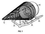
ここで図1〜5、8、および19を参照すると、流れアクセラレータシュラウド(20)は、最も複雑な水中翼形状を実現する重要な部品である。本発明の設計において用いるように、それは、タービンのローター部(30)を通る水流を加速するためにシュラウドの後ろに負圧領域を生成するために、好ましくは、非対称の水中翼形状、そして最も好ましくは、S字形/複曲水中翼形状(図5a、21)、または言い換えると大体S字形複曲形状(図9)を有する。アクセラレータシュラウドの壁の断面は、S字形複曲でないが、非常に従来の水中翼形状(図5b、24)に似ている水中翼形状でもあり得る。アクセラレータシュラウドは、アクセラレータシュラウドの外側周辺の周囲流速と比較してタービンの内部の水の流れを加速する。アクセラレータシュラウドは、好ましくは、4つの部分、すなわち、入口ダクト(22)、ステーターハウジング(24)、ローターブレードシュラウド(38)(図10)、および後部整形板(28)から成る。これらの4つの構成要素は、好ましくは、単一の形状を一緒に形成し、それは、好ましくは、アクセラレータシュラウドの非対称の水中翼であり、それは、特定の好ましい実施形態において、S字形/複曲水中翼形状を有する。4つの全ての部分は、好ましくは、内側と外側の両方で完全に滑らかな表面を形成するために一緒に平らにされて、それらの上を、水はいかなる重大な乱流も引き起こさずに流れる。
Flow Accelerator Shroud with Circular Diffuser With reference to FIGS. 1-5, 8 and 19, the flow accelerator shroud (20) is an important component for achieving the most complex hydrofoil shapes. As used in the design of the present invention, it is preferably an asymmetric hydrofoil shape, and most often, to create a negative pressure region behind the shroud to accelerate the water flow through the rotor section (30) of the turbine. Preferably, it has an S-shaped / compound hydrofoil shape (FIGS. 5a, 21), or in other words a generally S-shaped compound shape (FIG. 9). The cross section of the wall of the accelerator shroud is not an S-shaped compound, but can also be a hydrofoil shape that is very similar to the conventional hydrofoil shape (FIGS. 5b, 24). The accelerator shroud accelerates the flow of water inside the turbine compared to the ambient flow velocity around the outside of the accelerator shroud. The accelerator shroud preferably consists of four parts: an inlet duct (22), a stator housing (24), a rotor blade shroud (38) (FIG. 10), and a rear shaping plate (28). These four components preferably form a single shape together, which is preferably an asymmetric hydrofoil of an accelerator shroud, which, in certain preferred embodiments, is S-shaped / compound. It has a hydrofoil shape. All four parts are preferably flattened together to form a perfectly smooth surface, both inside and outside, over which water flows without causing any significant turbulence. ..
入口ダクト(22)は、水流をローター部(30)に送って、水流をアクセラレータシュラウドの外側のステーターハウジング(24)を越えて、そして内側のローターブレードシュラウド(38)を越えて導くのに役立つ。このステーターハウジング外面およびローターブレードシュラウド内面は、アクセラレータシュラウドの全体形状の一部である。入口ダクトは、動作の間にローター部を導く前方スラスト軸受も含む。 The inlet duct (22) serves to direct the water flow to the rotor section (30) and direct the water flow over the outer stator housing (24) of the accelerator shroud and beyond the inner rotor blade shroud (38). .. The outer surface of the stator housing and the inner surface of the rotor blade shroud are part of the overall shape of the accelerator shroud. The inlet duct also includes a front thrust bearing that guides the rotor section during operation.
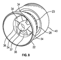
ステーターハウジング(24)は、環状発生器のステーターを備えるすべての金属、好ましくは銅コイル(25)ならびにタービンから発生する電気エネルギーを伝達する従来の電気的配線(図示せず)を含む。ステーターハウジングは、ローター部が回転する回転ローラー/玉軸受(あるいは他の軸受または低摩擦ポリマーブッシング)(26)も含む。 The stator housing (24) includes all metal with an annular generator stator, preferably a copper coil (25), as well as conventional electrical wiring (not shown) that transfers the electrical energy generated by the turbine. The stator housing also includes a rotating roller / ball bearing (or other bearing or low friction polymer bushing) (26) in which the rotor section rotates.
ローターブレードシュラウド(38)の外面は、アクセラレータシュラウドの一部をなすが、ローターブレード先端(33)に取り付けられる別の部品であり、アクセラレータシュラウド内部で主ローターによって回転する。以下に更に詳細に説明される。 The outer surface of the rotor blade shroud (38), which forms part of the accelerator shroud, is another component attached to the tip of the rotor blade (33) and is rotated by the main rotor inside the accelerator shroud. It will be described in more detail below.
ステーターハウジング(24)およびローターブレードシュラウド(38)の後ろに位置する後部整形板(28)は、水流をアクセラレータシュラウド(20)の出口に導いて、好ましくは、いかなる乱流またはドラッグも生成することを回避するために後端にそぎ端(29)を有する。後部整形板は、回転する間にローター部が押し付けられる後方/後部スラスト軸受(26)(図9)も含む。 The rear shaping plate (28), located behind the stator housing (24) and rotor blade shroud (38), directs the water flow to the outlet of the accelerator shroud (20), preferably producing any turbulence or drag. Has a peg end (29) at the rear end to avoid. The rear shaping plate also includes rear / rear thrust bearings (26) (FIG. 9) to which the rotor portion is pressed during rotation.
環状拡散器(40)は、好ましくは、非対称の水中翼形リングでもあって、好ましくは、アクセラレータシュラウド(20)より大きな直径を有する。環状拡散器(40)は、アクセラレータシュラウドの後ろに位置して、好ましくは、アクセラレータシュラウド(20)の後端といくぶん重なる。それはアクセラレータシュラウドと非常に類似の方法で動作して、タービンの後で負圧領域を更に増加させる。アクセラレータシュラウドおよび環状拡散器の協働および結果として生じる相乗効果のため、ローター部中の流速のより大きな増大がある。通常、好ましくはそぎ端である、(最終的な)環状拡散器の後縁部の後の比較的密接した(例えば、約4〜6インチ)位置に、後部野生生物および破片排除装置は取り付けられる。例えば、一方が他方の後ろに配置される、第2の環状拡散器(42)およびあるいは更に第3の環状拡散器(44)のような、一つ以上の環状拡散器を使用するために、特定の水流条件が有利であり得るいくつかの例があり得る。(図6〜7) The annular diffuser (40) is also preferably an asymmetric hydrofoil ring, preferably having a larger diameter than the accelerator shroud (20). The annular diffuser (40) is located behind the accelerator shroud and preferably overlaps somewhat with the rear end of the accelerator shroud (20). It operates in a very similar way to the accelerator shroud, further increasing the negative pressure region after the turbine. Due to the cooperation of the accelerator shroud and the cyclic diffuser and the resulting synergies, there is a greater increase in flow velocity in the rotor section. The posterior wildlife and debris eliminator is mounted at a relatively close (eg, about 4-6 inch) position behind the trailing edge of the (final) annular diffuser, which is usually preferably the end. .. For example, to use one or more annular diffusers, such as a second annular diffuser (42) and / or even a third annular diffuser (44), one placed behind the other. There may be some examples where certain water flow conditions can be advantageous. (Figs. 6-7)
ローターアセンブリ
ここで図10〜15を参照すると、本発明の流体動力タービンは、好ましくは、開いた中央部(37)を有する。一つには、ブレードがローター部の中心の近くの水中を移動して、したがって抽出する価値がある充分なリフトまたは十分なエネルギーを生成しない低速のため、これは本発明の設計において有利である。実際に、中心部は、一般に、それがより大きい濡れた表面および水中を移動するのに必要な付加的なウェイトによって生じる余分の抵抗によってローターに悪影響を及ぼす。ローターブレード(34)の先端は、より高い速度で水中を進み、したがって実質的により多くのリフトを生じて、実質的により大きなエネルギー抽出を可能にする。タービンのサイズ、装置の位置の流速、および他の部位特異的ニーズに応じて、開いた中央部とブレードおよびハブサイズ間の比率は、どこでも約40%のブレード、60%のオープンスペース〜約80%のブレード、20%のオープンスペースであり得る。本発明によるタービンは、リフトを生じるためにローター部の周辺に沿って全径の大部分、通常は約60%以上、好ましくは直径の約2/3を有利に使用する。これは、残りの小さい部分を、例えば、好ましい実施形態でセンターオープン(37)の全径の約1/3を残す。ローターの中心部を除去することは、ローターの全体の重量を減らして、中実のプロフィール部が生じさせる濡れた表面積および抵抗も減らす。したがって、本発明の設計は、より小さい重量を有する、そしてより小さい濡れた領域およびより小さい抵抗を有する、より小さいブレード領域を使用するより有効なローター部を作製する。それはより高い回転速度で回転することができて、より多くのエネルギーが抽出されることを可能にする。後述する野生生物および破片排除装置に更なる利益になる二次的な効果もある。
Rotor Assembly With reference to FIGS. 10-15, the fluid powered turbine of the present invention preferably has an open central portion (37). This is advantageous in the design of the present invention, in part because the blade moves in the water near the center of the rotor and therefore does not produce enough lift or enough energy to extract. .. In fact, the center generally adversely affects the rotor due to the extra resistance created by the larger wet surface and the additional weights it needs to move in the water. The tip of the rotor blades (34) travels underwater at a higher rate, thus producing substantially more lift and allowing substantially greater energy extraction. Depending on the size of the turbine, the flow velocity at the location of the equipment, and other site-specific needs, the ratio between the open center and the blade and hub size is about 40% blade everywhere, 60% open space to about 80. It can be% blade, 20% open space. Turbines according to the invention advantageously use most of the total diameter, usually about 60% or more, preferably about 2/3 of the diameter, along the periphery of the rotor portion to produce a lift. This leaves the remaining small portion, for example, about one-third of the total diameter of the center open (37) in a preferred embodiment. Removing the center of the rotor reduces the overall weight of the rotor and also reduces the wet surface area and resistance created by the solid profile. Therefore, the design of the present invention creates a more effective rotor section that uses a smaller blade area with less weight and less wet area and less resistance. It can rotate at higher rotational speeds, allowing more energy to be extracted. There are also secondary benefits to the wildlife and debris removal devices described below.
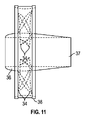
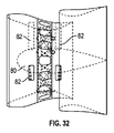
好ましくは環状であり、且つ好ましくは開いた中央部(37)を囲むセンターハブ(36、80)は、ローターブレードの付け根(39)を取り付けるためにも使われる。(図11〜12および31)中実であるセンターハブ(80)は、好ましくは、対称の水中翼形状を有するが、開いた中央部を備えたセンターハブ36は、好ましくは、非対称の水中翼形状を有し、外輪はタービンの外側の近くにあり、そして内輪はハブの中心を向いている。センターハブによって生じるリフトは、アクセラレータシュラウド(20)および環状拡散器(40)により作製されるタービンの後で負圧領域を更に増加させるのを助ける。この効果は、ローターブレード部を通る水流の加速を増大させて、相乗効果および結果として生じるより高い発電に寄与する。
Center hubs (36, 80), preferably annular and preferably surrounding an open central portion (37), are also used to attach the base (39) of the rotor blades. (FIGS. 11-12 and 31) The solid center hub (80) preferably has a symmetrical hydrofoil shape, whereas the
ローターブレードシュラウド(38)(主ローターの外部リングとも呼ばれる)は、ブレード(34)の末端/先端(33)が取り付けられるところである。(図10)このローターブレードシュラウド(38)は、アクセラレータシュラウド(20)の水中翼形状の一部をなす。それは、それがローターブレード(34)とともに回転することを可能にするアクセラレータシュラウドから分離する要素であるが、ローターブレードシュラウドの表面は、好ましくは、アクセラレータシュラウド、およびローターブレードシュラウドの両方の内面、一つの滑らかな曲線を生じるために、アクセラレータシュラウド(20)の内面に完全に合致している。ステーターハウジング(24)内面に面する、ローターブレードシュラウドの外面は、好ましくは、アクセラレータシュラウドにはめ込まれて、平坦面を有し、そこでは電気エネルギーを発生するためにステーターの銅コイル(25)を通過して回転する永久磁石(32)が設置される。ローターブレードシュラウド(38)も先端渦動を排除して、抵抗および乱流を減らして、より高い効率およびより大きなエネルギー抽出に結果としてなる。 The rotor blade shroud (38) (also called the outer ring of the main rotor) is where the end / tip (33) of the blade (34) is attached. (FIG. 10) The rotor blade shroud (38) forms part of the hydrofoil shape of the accelerator shroud (20). It is an element that separates from the accelerator shroud, which allows it to rotate with the rotor blade (34), but the surface of the rotor blade shroud is preferably the inner surface of both the accelerator shroud and the rotor blade shroud, one. It fits perfectly on the inner surface of the accelerator shroud (20) to produce two smooth curves. The outer surface of the rotor blade shroud, which faces the inner surface of the stator housing (24), is preferably fitted into the accelerator shroud and has a flat surface, where the copper coil (25) of the stator is used to generate electrical energy. A permanent magnet (32) that passes and rotates is installed. The rotor blade shroud (38) also eliminates tip vortices, reducing resistance and turbulence, resulting in higher efficiency and greater energy extraction.
ここで図11〜15を参照すると、ローターブレード(34)の効率は、後述するように、やはり好ましくは最適化される、好ましくは非対称の水中翼形状を用いて上昇する。水中翼のコードまたは断面(35)とも呼ばれる、この形状は、各ブレードの効率の上昇に結果としてなって、サイズが小さくなって、他の設計と比較してブレードの数を減少させる。より小さいローターブレード(34)は、より小さい濡れた領域を有し、従ってより小さい抵抗を発生する。水中翼形状が生成するリフトの量は、コード/断面(35)(図15)の形状、コード(74)の長さ、および水中翼のコード(76)の厚みにより決定される。(図13)本発明による設計において、コード(74)の長さおよび/またはコード(76)の厚みの一方または両方とも、好ましくは、ブレード付け根(39)とブレード先端(33)の間で変化する。これは、水中翼形状が水中を進む速度に関連してそれによって生じるリフトを最適化する。本発明による設計のローター部に配置されるブレードの数は、特定の用途におけるタービンのサイズおよび水の流速に応じて変化し得る。 Here, with reference to FIGS. 11-15, the efficiency of the rotor blades (34) is increased using a preferably optimized, preferably asymmetric hydrofoil shape, as will be described later. This shape, also called the hydrofoil cord or cross section (35), results in increased efficiency of each blade, resulting in smaller size and reduced number of blades compared to other designs. The smaller rotor blades (34) have smaller wet areas and therefore generate less resistance. The amount of lift produced by the hydrofoil shape is determined by the shape of the cord / cross section (35) (FIG. 15), the length of the cord (74), and the thickness of the hydrofoil cord (76). FIG. 13 In the design according to the invention, one or both of the length of the cord (74) and / or the thickness of the cord (76) preferably varies between the blade root (39) and the blade tip (33). do. This optimizes the lift it produces in relation to the speed at which the hydrofoil shape travels underwater. The number of blades placed in the rotor section of the design according to the invention can vary depending on the size of the turbine and the flow rate of water in a particular application.
ローターブレードが取り付けられる角度/入射角(72)(図13)は、水中を進むブレードの迎え角または入射角を最適化するために調整できる変数でもある。ブレード表面をこえる水の層流または少なくともほぼ層流を生じるために、ローターの回転数により決定される最適角度を使用することが好ましい。この流れが乱流または著しく非薄流である場合、水中翼はより小さいリフトを生じ、したがってより少ないエネルギーを抽出できる。ブレードの先端は、一回転数を完了するためにより長い距離を進むという事実によって、ブレードの付け根より速く水中を進む。したがって、ブレードの入射角は、最適角度であるために、ブレードの付け根(39)からブレードの先端(33)に有利に段階的に減少する。角度のこの変化は、ブレードのねじり(78)と呼ばれている。ねじりは、好ましくは、あらゆる断面でローターブレード最大リフトを生じて、したがって効率および動力の抽出を増加させるように設計される。 The angle at which the rotor blades are mounted / angle of incidence (72) (FIG. 13) is also a variable that can be adjusted to optimize the angle of attack or angle of attack of the blade traveling underwater. It is preferable to use the optimum angle determined by the rotation speed of the rotor in order to generate a laminar flow of water beyond the blade surface or at least almost a laminar flow. If this flow is turbulent or significantly non-thin, the hydrofoil will produce a smaller lift and thus be able to extract less energy. The tip of the blade travels underwater faster than the base of the blade due to the fact that it travels a longer distance to complete one revolution. Therefore, the angle of incidence of the blade gradually decreases from the base of the blade (39) to the tip of the blade (33) because it is the optimum angle. This change in angle is called blade twist (78). Torsion is preferably designed to produce rotor blade maximum lift in any cross section and thus increase efficiency and power extraction.
本発明による水中翼形状が、それらがいろいろな速度で水中を進むときに最適であるために、それらは、好ましくは、コード(74)のいろいろな長さおよびプロフィール/コード(76)のいろいろな厚みを有する。好ましくは、ブレードがより高い速度で水中を進行して、最も大きな量のリフトを生じる表面積を増加させるために、ブレードの厚み(76)は増加し、そして/またはコード長(74)はブレードの付け根からブレードの先端の方へ増加する。このように、ブレードは、最も好ましくは、それらがハブから放射状に伸びるにつれて、サイズおよび厚みの両方とも増加する。コード長および厚みのこれらの増大は、より高い効率およびより大きな力の抽出に結果としてなる。 They are preferably of different lengths of cords (74) and of different profiles / cords (76), as the hydrofoil shapes according to the invention are optimal when they travel underwater at different speeds. Has a thickness. Preferably, the blade thickness (76) is increased and / or the cord length (74) of the blade is increased in order for the blade to travel in water at a higher speed to increase the surface area that produces the largest amount of lift. It increases from the base to the tip of the blade. Thus, the blades most preferably increase in both size and thickness as they extend radially from the hub. These increases in cord length and thickness result in higher efficiency and greater force extraction.
ローターブレード水中翼形状(35)、コード(74)の長さ、プロフィール/コード(76)の厚み、入射角の程度(72)、および各ローターブレードのねじり(78)、およびブレードの数は、水の特定地域向けの流れ条件および他の位置的ニーズに適応するために、用途ごとに有利に変更できる。 The rotor blade hydrofoil shape (35), cord (74) length, profile / cord (76) thickness, incident angle degree (72), and each rotor blade twist (78), and number of blades It can be changed favorably on a per-use basis to accommodate specific regional flow conditions and other locational needs of water.
野生生物および破片排除装置
ここで主に図16〜18を参照すると、炭素排出ゼロで再生可能資源からエネルギーを発生する流体動力タービンは、天然資源および大気に対してだけでなく、海洋および野生生物に対しても環境配慮型でなければならない。本発明は、指定されたサイズを超えるいかなる海洋生物および浮いているかまたは水中の破片も本発明の流体動力タービンのローターからそらせて、保つ。タービンのノズル部に入ることができない海洋生物または破片のサイズは、前部および後部排除装置のデフレクターロッド(14)の間隔/距離(15)によって定められる。本発明において、デフレクターロッドは、計画的に、各々と平行して走り、そしてロッド(15)間の距離が等しいことを確実にするためにそれらの全長にわたって均一に離間する。間隔(15)の距離は、海洋野生生物のサイズおよび種、ならびに除外される、且つ動作の特定のサイトの位置的な必要に適応することになる破片のサイズにより決定される。それは、後部排除装置も使用されるときに、デフレクターロッド(14)間の隙間(15)より大きい、あらゆる海洋生物、例えば、魚、亀、海洋哺乳類、およびダイバーが、前方だけでなく後方からも流体動力タービンのローター部に入るのを防止する。
Wildlife and Debris Elimination Equipment Here, primarily referring to Figures 16-18, fluid-powered turbines that generate energy from renewable resources with zero carbon emissions are not only for natural resources and the atmosphere, but also for oceans and wildlife. It must also be environmentally friendly. The present invention keeps any marine organisms and floating or underwater debris exceeding the specified size deflected from the rotor of the fluid powered turbine of the present invention. The size of marine organisms or debris that cannot enter the nozzle of the turbine is determined by the spacing / distance (15) of the deflector rods (14) of the front and rear exclusion devices. In the present invention, the deflector rods systematically run parallel to each other and are evenly spaced over their entire length to ensure that the distances between the rods (15) are equal. The distance of the interval (15) is determined by the size and species of marine wildlife, as well as the size of debris that will be excluded and will adapt to the positional needs of the particular site of operation. It allows all marine organisms, such as fish, turtles, marine mammals, and divers, to be larger than the gap (15) between the deflector rods (14) when the rear exclusion device is also used, not only from the front but also from the rear. Prevents entry into the rotor section of fluid powered turbines.
本設計は、他の以前から知られている設計と対照をなす(例えば、米国特許第3986787号明細書、米国特許出願公開第2010/0007148(Al)号明細書、および米国特許第D614,560号明細書参照)。それらは、非平行であるデフレクターロッドによって特徴づけられる。ゆえに、ロッド間の開口部は、排除装置の一端に向ってより大きく/より広くなり、したがって海洋生物または破片の有限サイズへの侵入を制限しない。いくつかの他の従来の装置は、開口部の有限サイズを定める同心の円形デフレクターロッド(例えば、米国特許第D304,322号明細書および米国特許第5,411,224号明細書参照)として設計されるが、この種の構成は、本発明によるデフレクターロッドのようにすべての野生生物および破片を効果的に排除せず、それは流れ方向に関して斜めに整列配置される。同心の設計において、野生生物または破片は、リングの間に容易に引っかかることができる。本発明の設計において、排除される海洋生物または破片の正確なサイズは、デフレクターロッド(14)の間で選択される距離(15)によって有利に選択的に予め定めることができる。 This design contrasts with other previously known designs (eg, U.S. Pat. No. 3,986,787, U.S. Patent Application Publication No. 2010/0007148 (Al), and U.S. Pat. No. D614,560. (Refer to the specification). They are characterized by deflector rods that are non-parallel. Therefore, the openings between the rods become larger / wider towards one end of the exclusion device and thus do not limit the entry of marine organisms or debris into a finite size. Some other conventional devices are designed as concentric circular deflector rods that define a finite size of the opening (see, eg, US Pat. Nos. D304,322 and US Pat. Nos. 5,411,224). However, this type of configuration does not effectively eliminate all wildlife and debris like the deflector rods according to the invention, it is aligned diagonally with respect to the flow direction. In a concentric design, wildlife or debris can easily get caught between the rings. In the design of the present invention, the exact size of the marine organisms or debris to be excluded can be advantageously and selectively predetermined by the distance (15) selected between the deflector rods (14).
海流および川流は、多くの種類の浮いている破片を含む。この破片は、表面に浮いているかまたはいろいろな深さで水中にあり得る。したがって、タービンへの損傷を防止し、そして連続して途切れない電気出力を確実にするために、この種の破片を流体動力タービンのローター部の外に可能な限り保つことが好ましい。本発明による設計は、デフレクターロッドの間隔の指定されたサイズ(15)を超えるいかなる破片も効果的にそらせて、中に入れない。 Ocean and river currents contain many types of floating debris. This debris can be floating on the surface or in water at various depths. Therefore, it is preferable to keep this type of debris out of the rotor section of the fluid powered turbine as much as possible to prevent damage to the turbine and to ensure continuous and uninterrupted electrical output. The design according to the invention effectively deflects and does not allow any debris that exceeds the specified size (15) of deflector rod spacing.
本発明による流体動力タービンは、好ましくは、2つの野生生物および破片排除装置、タービンの入口(22)の前方に1つ(10)およびタービンの出口の後ろに1つ(18)を有する。前方の野生生物および破片排除装置(10)は、タービンの前方に設置されて、アクセラレータシュラウド(20)の入口(22)を保護し、そして好ましくはタービンの支持構造(50、52)だけでなくアクセラレータシュラウドの前部にも取り付けられる。排除装置のデフレクターロッド(14)は、小型タービンの1/4インチから非常に大きなユニットの約2インチまで、タービンのサイズに応じていろいろな直径を有する金属、ガラス繊維、または合成材料で作られる。デフレクターロッドは、好ましくは、断面が水中翼/涙滴型(14)であり(図18)、鈍端は水流に向いて、尖っている先端は後縁部である。この構成は、一つ以上の他の構成要素、例えばアクセラレータシュラウド(20)、環状拡散器(40)、および/またはローターブレード(34)の効率を妨げることがあり得る水流の乱流を回避するのに役立つ。 The fluid powered turbine according to the invention preferably has two wildlife and debris eliminators, one (10) in front of the turbine inlet (22) and one (18) behind the turbine outlet. A front wildlife and debris eliminator (10) is installed in front of the turbine to protect the inlet (22) of the accelerator shroud (20), and preferably not only the turbine support structure (50, 52). It can also be attached to the front of the accelerator shroud. The deflector rod (14) of the eliminator is made of metal, fiberglass, or synthetic material with various diameters depending on the size of the turbine, from 1/4 inch of a small turbine to about 2 inches of a very large unit. .. The deflector rod is preferably hydrofoil / teardrop-shaped (14) in cross section (FIG. 18), with a blunt end facing the water stream and a pointed tip at the trailing edge. This configuration avoids turbulence of water flow that can interfere with the efficiency of one or more other components, such as accelerator shrouds (20), annular diffusers (40), and / or rotor blades (34). Useful for.
前部排除装置(14)の前端のデフレクターロッドが大体円錐状の形状を形成するように、第1/前部の野生生物および破片排除装置(10)は好ましくは組み込まれる。前端のデフレクターロッドは、好ましくはデフレクターロッドの内部間の指定された距離(15)と同じ内径を有する小さいリング(12)に取り付けられる。後端に、デフレクターロッドは、好ましくは、環状拡散器(40)より好ましくは大きな直径である大きいリング(16)に取り付けられる。前方リング(12)とデフレクターロッド(14)が取り付けられる後方リング(16)との差によって生じる円錐状の形状の傾斜は、いろいろな環境ニーズに適応するために変えることができる。前部排除装置は、好ましくは、有限サイズの野生生物および破片が入ることができるように維持するために、デフレクターロッド間の距離(15)とほぼ同一サイズである隙間を有して環状拡散器にわずかに重なるように配置される。それは、あらゆる野生生物、破片、海草、または水の流れに浮いておりタービンに入ることがあり得るあらゆる他のものをはじいてそらすために、円錐状の形状で設計される。 The first 1 / front wildlife and debris eliminator (10) is preferably incorporated so that the deflector rod at the front end of the anterior eliminator (14) forms a generally conical shape. The front end deflector rod is preferably attached to a small ring (12) having the same inner diameter as the specified distance (15) between the interiors of the deflector rod. At the rear end, the deflector rod is preferably attached to a large ring (16), which is preferably larger in diameter than the annular diffuser (40). The conical tilt caused by the difference between the front ring (12) and the rear ring (16) to which the deflector rod (14) is attached can be varied to accommodate a variety of environmental needs. The anterior exclusion device is preferably an annular diffuser with a gap that is approximately the same size as the distance between the deflector rods (15) to keep finite size wildlife and debris in. It is arranged so that it slightly overlaps with. It is designed in a conical shape to repel and distract any wildlife, debris, seagrass, or anything else that floats in the stream of water and can enter the turbine.
第2/後部の野生生物および破片排除装置18(図16および18)は、タービン出口の後ろに設置されて、(最終的な)環状拡散器の後縁部に取り付けられる。後部排除装置は、好ましくは、前部排除装置のロッド(14)と同じ予め定められた距離だけ互いから離れている平行したロッド部材のグリルまたはメッシュからも成り、後部排除装置の場合、最も好ましい構成は大体平らなものである。後部排除装置は、水流の方向に逆らっても、または例えば上げ潮から引き潮への変化の間のような流れが無い場合でも、より大きな海洋生物が後ろからローター部に入るのを防止する。排除装置のデフレクターロッドは、指定された距離より大きなあらゆる野生生物または破片がローター部に入ることを防止するために、前部の野生生物および破片排除装置と同じ指定された距離(15)まで離間する。排除装置の両方のすべてのデフレクターロッド(14)は、好ましくは、他の構成要素、例えば、ローターブレード、アクセラレータシュラウド、環状拡散器、および/またはセンターハブの一つ以上にあり得る水中翼形状に悪影響を及ぼす乱流および渦の生成を最小化するために、水中翼形の断面を有する。 The second / rear wildlife and debris removal device 18 (FIGS. 16 and 18) is installed behind the turbine outlet and attached to the trailing edge of the (final) annular diffuser. The rear exclusion device preferably also comprises a grille or mesh of parallel rod members separated from each other by the same predetermined distance as the rod (14) of the front exclusion device, most preferably in the case of a rear exclusion device. The composition is generally flat. The rear exclusion device prevents larger marine organisms from entering the rotor from behind, even in the direction of the water stream, or even in the absence of a flow, such as during a change from rising tide to ebb tide. The deflector rod of the eliminator is separated by the same specified distance (15) as the front wildlife and debris eliminator to prevent any wildlife or debris larger than the specified distance from entering the rotor section. do. Both all deflector rods (14) of the eliminator preferably have a hydrofoil shape that can be on one or more of the other components, such as rotor blades, accelerator shrouds, annular diffusers, and / or center hubs. It has a hydrofoil cross section to minimize adverse turbulence and vortex formation.
デフレクターロッドの間隔(15)を通過できるより小さい海洋生物は、記載されたタービン実施形態の大部分に開いた中央部(37)を有する円筒状センターハブ(36)を安全に通過するための第2の経路を有利に提供される。ローター部の開いた中央部は上に記載されている。センターハブの水流速がブレードがある外側より速いので、より小さい海洋生物は、その開口部に吸引されて、無傷で出ることができる。開いた中央部の直径は、タービンの性能に著しい影響を及ぼすことなく広く変更できる。最適直径は、用途ごとに算出することができて、特定の好ましい実施形態において、通常は、ローター部の全径のほぼ1/3である。開いた中央部(37)を通る加速した水の流れは、タービンの内部を通る小さい野生生物および小さい破片を安全に搬送するのに役立つ。 Smaller marine organisms capable of passing through the deflector rod spacing (15) are the first to safely pass through a cylindrical center hub (36) having a central portion (37) open to most of the described turbine embodiments. Two routes are offered advantageously. The open central part of the rotor part is described above. Since the water flow velocity of the center hub is faster than the outside with the blade, smaller marine organisms can be sucked into its opening and exit intact. The diameter of the open central part can be widely changed without significantly affecting the performance of the turbine. The optimum diameter can be calculated for each application and, in certain preferred embodiments, is usually approximately one-third of the total diameter of the rotor portion. The accelerated flow of water through the open central part (37) helps to safely transport small wildlife and small debris through the interior of the turbine.
どの取付け方法が選択されても、本発明によるタービンは、好ましくは、それらが水流が来ている方向に常に正確に向くことを意味する、自動的に自己整列する。これは、好ましくは、固定尾部舵(60)のタービンの後の取付けにより達成される。固定尾部舵は、好ましくは水中翼形状であり、そしてユニットを水流の流れの方向にまっすぐに向ける。この特徴によって、装置は、流れが来ている方向に正確に向くことができて、その結果、タービンの水中翼形の構成要素を通過する水は、すべての水中翼形の表面を最適角度で流れる。これは、2つの側の間の圧力差を最適化して、水中翼形状の相乗効果を増加させて、水の層流を確実にするのを助ける。 Regardless of which mounting method is selected, the turbines according to the invention preferably automatically self-align, which means that they are always oriented exactly in the direction in which the water flow is coming. This is preferably achieved by mounting the fixed tail rudder (60) after the turbine. The fixed tail rudder is preferably hydrofoil shaped and directs the unit straight in the direction of the stream of water. This feature allows the device to be oriented exactly in the direction in which the flow is coming, so that water passing through the components of the hydrofoil of the turbine will be optimally angled over the surface of all hydrofoils. It flows. This helps optimize the pressure difference between the two sides, increase the synergistic effect of the hydrofoil shape, and ensure laminar flow of water.
発明の流体動力タービンの設計は、水の流れが常に同じ側から、すなわち一方向性である。これによって、タービンは、多くの非対称の水中翼形状および流体力学効果を大きく利用できる。それらは、一緒に組み合わされるときに、非常に効率的なタービンに結果としてなる。双方向性タービンは、非対称の水中翼形状を使用することができず、したがってより非効率である。 The design of the fluid powered turbine of the invention is that the water flow is always from the same side, i.e. unidirectional. This allows the turbine to take advantage of many asymmetric hydrofoil shapes and hydrodynamic effects. They result in a highly efficient turbine when combined together. Bidirectional turbines cannot use asymmetric hydrofoils and are therefore more inefficient.
発明によるタービンは、それらの一方向性流れによってヴェントゥーリ/ベルヌーイ効果を一層利用するだけでなく、それらは、好適な非対称の水中翼形のアクセラレータシュラウドおよび/または環状拡散器、ならびに/あるいは好ましくは水中翼形のセンターハブを用いて更に流速を上げる。 Turbines according to the invention not only make better use of the Venturi / Bernoulli effect by their unidirectional flow, but they are also suitable asymmetric hydrofoil accelerator shrouds and / or annular diffusers, and / or preferably underwater. Further increase the flow velocity using a wing-shaped center hub.
環状発生器の設計は、好ましくは、ローターブレードシュラウド(38)に載置する磁石(32)と好ましくはアクセラレータシュラウド(20)に設置されるステーターハウジング(24)の銅または他の金属のコイル(25)とを有する。この設計は、エネルギーを機械的に抽出して、タービンの外に伝えるギアボックスまたはトランスミッションまたは油圧装置の必要をなくす。ギアボックス、トランスミッション、および油圧装置は、タービンが発生するエネルギーの一部を消費する摩擦を生じる。環状発生器の使用によって、本発明は、これらの摩擦/伝送損失を最小化して、より効率的なタービンまたは発生器を生じる。タービン内部で直接発生する電気エネルギーは、摩擦/伝送および電力損失を削減する電線(図示せず)を通して伝えられる。発生されたエネルギーは、それから、実際的であると考えられる場合はいつでも、タービンの外側に通常は設置されるインバータ/トランスに調整のために伝送される。本発明による好適な設計は、中心軸受を有する必要もなくす。それは、それによってタービンを通る流通領域内に設置されるいかなる固定構造(例えば、軸またはハブ)の必要も全くなくす。いかなる固定構造の欠如も、支柱または他の要素がその固定構造を支持するために必要でないことを更に意味する。 The design of the annular generator is preferably a copper or other metal coil of a magnet (32) mounted on the rotor blade shroud (38) and a stator housing (24) preferably mounted on the accelerator shroud (20). 25) and. This design eliminates the need for gearboxes or transmissions or hydraulics that mechanically extract energy and transfer it out of the turbine. Gearboxes, transmissions, and hydraulics generate friction that consumes some of the energy generated by the turbine. By using an annular generator, the present invention minimizes these friction / transmission losses to result in a more efficient turbine or generator. The electrical energy generated directly inside the turbine is transmitted through wires (not shown) that reduce friction / transmission and power loss. The energy generated is then transmitted for adjustment to an inverter / transformer, which is usually installed outside the turbine, whenever it is considered practical. A suitable design according to the invention also eliminates the need to have a central bearing. It eliminates the need for any fixed structure (eg, shaft or hub) thereby installed in the distribution area through the turbine. The lack of any fixed structure further means that struts or other elements are not needed to support the fixed structure.
このタービンのアクセラレータシュラウド(20)、環状拡散器(40)、水中翼形のセンターハブ(36、80)、およびローターブレード(34)は、好ましくは、例えば、炭素繊維、アラミド繊維、ガラス繊維のような複合建材、あるいは固体繊維および樹脂またはオーバー・ストラクチュラル・フォーム・コア材料またはハネコムコア材料の類似物から構成される。ステーターハウジングのようないくつかの部品は、好ましくは、ステーターの銅コイル(25)を収容するために中空である。入口ダクト(22)、アクセラレータシュラウド(20)の後部整形板(28)、および環状拡散器(40)のような他の部品は、いくつかの好ましい実施形態において、中実またはサンドイッチ構造であり、そして内側で中空のままであり、水中に入れられるときに、水で選択的に満たされるオプションを有する。中空部品の内部の適切な(水深のための)構造支柱については、それらは、水浸しの水圧に耐えることが可能である。サンドイッチ構造の場合、利用されるこれらの複合材料は、自然に浮揚可能であって、タービンを浮かせ続ける。複合材料が、この流体動力タービンの構成に理想的に適しているけれども、装置は、特定の用途に適していると考えられる鋼、アルミニウム、チタン、または他の金属合金から造ることもできる。このタービンの全浮力は大抵正であって、バラストを使用して、それを水中に保つことができる。タービンは、中空の区画を水で満たすことができることによって、水中に沈めることもできる。適切な量のバラストの設置または特定の区画の水充填によって、いろいろな用途に対して、タービンの全浮力は、選択的にタービンを正に浮揚可能であるか、中立的に浮揚可能であるか、負に浮揚可能であるよう制御できる。 The accelerator shroud (20), annular diffuser (40), submersible blade-shaped center hubs (36, 80), and rotor blades (34) of this turbine are preferably made of, for example, carbon fiber, aramid fiber, glass fiber. Composed of such composite building materials, or analogs of solid fibers and resins or overstructural foam core materials or honeycomb core materials. Some components, such as the stator housing, are preferably hollow to accommodate the copper coil (25) of the stator. Other components such as the inlet duct (22), the rear shaping plate (28) of the accelerator shroud (20), and the annular diffuser (40) are, in some preferred embodiments, solid or sandwiched structures. It remains hollow on the inside and has the option of being selectively filled with water when submerged. For proper structural struts (for water depth) inside hollow parts, they are capable of withstanding the water pressure of flooding. In the case of sandwich structures, these composites utilized are naturally levitable and keep the turbine floating. Although composites are ideally suitable for the construction of this fluid powered turbine, the equipment can also be made from steel, aluminum, titanium, or other metal alloys that are considered suitable for a particular application. The total buoyancy of this turbine is usually positive and a ballast can be used to keep it in the water. The turbine can also be submerged by being able to fill the hollow compartment with water. With the installation of the appropriate amount of ballast or water filling in a particular compartment, for a variety of applications, the total buoyancy of the turbine can selectively levitate the turbine positively or neutrally. , Can be controlled to be negatively levitable.
装置の好適な自己整列機能によって、このタービンは一方向性流れタービンであり得る。一方向性タービンにおいて、タービンの前方から常に来ている水流の存在は、設計における非対称または一方向性水中翼形状の使用を可能にする。したがって、基本構成要素、すなわち、ローターブレード、アクセラレータシュラウド、環状拡散器、中空センターハブ、尾部舵、および/または野生生物および破片排除装置のいずれかまたは全部は、少なくともある程度まで、非対称の水中翼形状から有利に成ることができる。非対称または一方向性の水中翼形状は、対称水中翼および双方向性水中翼より非常に効率的である。 Due to the suitable self-alignment function of the device, this turbine can be a one-way flow turbine. In a one-way turbine, the presence of a stream of water always coming from the front of the turbine allows the use of asymmetric or one-way hydrofoil shapes in the design. Therefore, any or all of the basic components, namely rotor blades, accelerator shrouds, annular diffusers, hollow center hubs, tail rudders, and / or wildlife and debris eliminators, are asymmetric hydrofoils, at least to some extent. Can be advantageous from. Asymmetric or unidirectional hydrofoils are much more efficient than symmetrical and bidirectional hydrofoils.
非対称の水中翼形状、すなわち、アクセラレータシュラウド、ローターブレード、環状拡散器、中空センターハブ、および/または野生生物と破片排除装置を含むそれらの要素の関係および協働は、相互に有益な相乗効果を生じ、それは、これらの要素のより多くが非対称の水中翼プロフィールを備えるにつれて強化される。最も好ましい実施形態において、これらの要素の全5つは、互いの存在から利益を得て、一緒に組み合わされるときに、それらの効果は、それらが個々にまたは別々に生じるより非常に大きな負圧領域をタービンの後ろに生じるように増幅される。換言すれば、複数の要素の効果は、全体として、個々の複数の要素の合計より大きい。この相乗効果は、ローター部を通る流れのより大きな加速を生じ、そこでは非対称の水中翼形ブレードは、より大きな利点を得て、より大きな速度または回転数で回転することが可能である。これらの複合効果は、相互に有益であり、且つ本発明者により開発された「フローアクセラレーション技術」のおかげでより大きなエネルギー抽出を可能にする非常により高い効率をもたらす相乗効果につながる。 Asymmetric hydrofoil shapes, ie, the relationships and collaboration of those elements, including accelerator shrouds, rotor blades, annular diffusers, hollow center hubs, and / or wildlife and debris eliminators, have mutually beneficial synergies. It arises and it is strengthened as more of these elements have an asymmetric hydrofoil profile. In the most preferred embodiment, when all five of these elements benefit from the presence of each other and are combined together, their effect is a much greater negative pressure than they occur individually or separately. The region is amplified to occur behind the turbine. In other words, the effect of the elements as a whole is greater than the sum of the individual elements. This synergistic effect results in greater acceleration of the flow through the rotor section, where the asymmetric hydrofoil blade can rotate at higher speeds or speeds with greater advantage. These combined effects are mutually beneficial and lead to synergistic effects that result in much higher efficiencies that allow for greater energy extraction thanks to the "flow acceleration technology" developed by the present inventor.
図36を参照すると、表は、一つの好ましい実施形態に対して、水中翼形のアクセラレータシュラウドの存在が、どのようにして、周囲流速と比較して、ノズル部中の流速の指数関数的な加速をもたらすかを示す。 Referring to FIG. 36, the table shows, for one preferred embodiment, how the presence of an underwater blade-shaped accelerator shroud is exponential in the flow velocity in the nozzle section compared to the ambient flow velocity. Indicates whether it will bring acceleration.
図36に示すデータは、1.5メートルの直径のローターを備えた流体動力タービンの2つの異なる設計間の増加した周囲流速による出力電力の差を示す。正方形付きの線は、シュラウドを備えず、ハブおよび3つのブレードを単に備える流体動力タービンを表す(それは、世界中滴に流体動力タービンに使用される最も一般的に用いられる設計である)。三角形付きの線は、水中翼形アクセラレータシュラウド、環状拡散器、および開いたセンターハブを利用する本発明の出力を示す。これは、図35に表される水中翼形状と類似の水中翼形状を有するアクセラレータシュラウド内に含まれる同じローターアセンブリに対して同じ関係である。電力の増加が、3の次数の指数関数的電力によるということが分かる。流速の低い範囲で、(例えば、このタイプの水力タービンの適用の大多数を表す約3kn)、比較関係が流速の変化にそれほど影響されないということも分かる。したがって、この一般的な動作範囲で、出力電力の相対的増加を最大にするために、シュラウド部材(および他の構成要素および関係)の設計を最適化することは、特に重要である。 The data shown in FIG. 36 show the difference in output power due to the increased ambient flow velocity between two different designs of fluid powered turbines with rotors with a diameter of 1.5 meters. The squared wire represents a fluid powered turbine without a shroud, simply with a hub and three blades (it is the most commonly used design used in fluid powered turbines for drops worldwide). The triangular lines show the power of the invention utilizing a hydrofoil accelerator shroud, an annular diffuser, and an open center hub. This is the same relationship for the same rotor assembly contained within an accelerator shroud that has a hydrofoil shape similar to that shown in FIG. 35. It can be seen that the increase in power is due to the exponential power of the third order. It can also be seen that in the low flow rate range (eg, about 3 kn, which represents the majority of applications of this type of hydraulic turbine), the comparative relationship is less affected by changes in flow rate. Therefore, it is particularly important to optimize the design of the shroud member (and other components and relationships) in order to maximize the relative increase in output power in this general operating range.
本発明のタービンの上昇した効率を示す別の方法は、他の極めて効率的な市販のタービンとの比較にある。世界の最も成功した流体動力タービンメーカーおよび設置者の一つは、それが最も効率的なものであると主張する流体動力タービンの新規な設計を最近開発した。それは、外部シュラウドおよび開いたセンターハブを備えた16mの直径のローター部を有し、且つ2.2MWを発生することが可能であると主張する双方向性タービンである。本発明の設計方法を利用して、同じ16mの直径のローター部を有するタービンは、我々の「理論的な計算」によれば、3.88MWを発生する。これは、同一サイズのタービンに対して電気出力の76%の増加を表す。 Another way to show the increased efficiency of the turbines of the present invention is in comparison with other highly efficient commercial turbines. One of the world's most successful fluid-powered turbine manufacturers and installers has recently developed a new design for fluid-powered turbines that they claim to be the most efficient. It is a bidirectional turbine that has a 16 m diameter rotor with an external shroud and an open center hub and claims to be capable of generating 2.2 MW. Utilizing the design method of the present invention, a turbine with the same 16 m diameter rotor section will generate 3.88 MW according to our "theoretical calculation". This represents a 76% increase in electrical output for turbines of the same size.
下記は、本発明による流体動力タービン設計の出力予測のために使用する計算である。 The following are the calculations used to predict the output of a fluid powered turbine design according to the present invention.

取付け方法
本発明による流体動力タービンは、使用可能な出力を発生させるために、実際にいかなる水の運動体にも取り付けることができるか、または水中を移動できる。これらの流体動力タービンのための取付けおよび配備方法について5つの主要な方法がある。
Mounting Method The fluid-powered turbine according to the invention can be mounted on, in fact, any water moving body or can move underwater in order to generate a usable output. There are five main installation and deployment methods for these fluid powered turbines.
杭装備(図21、22):タービンのユニットまたは複数のユニットは、杭装備の装置となり得、それは、一組の回転スラスト軸受および上部(53)の圧縮回動軸受を有する海底または河床に打ち込まれる杭(52)から成る。タービンが位置する取付構造(50)に取り付けられるより大きなパイプは、その固定杭(52)および軸受(53)にスリーブでつなぐ。取付構造(50)は、パイプ(52)からかんぬきをはずすことができて、パイプ内部に保守およびタービン取り外しのために抜くことができる電気用プラグ(53)を備えている。この装置によって、タービンユニットが枢動することができて、タービンは水流の方向に正確に向くように360度自由に回転できる。この種の装置は、非常に小さい海底足跡および環境への最小の影響も有する。この取付けにおいて、電力は、ケーブルのねじりおよび旋回動作に関するいかなる制約も回避するために、スリーブ内部の一組の銅リングおよび炭ブラシ(53)により伝送される。 Pile equipment (FIGS. 21 and 22): A turbine unit or multiple units can be a pile equipment device, which is driven into a seabed or riverbed with a set of rotary thrust bearings and an upper (53) compression rotary bearing. It consists of a pile (52). Larger pipes attached to the attachment structure (50) where the turbine is located are sleeved to its fixed piles (52) and bearings (53). The mounting structure (50) includes an electrical plug (53) that can be removed from the pipe (52) and can be pulled out inside the pipe for maintenance and turbine removal. This device allows the turbine unit to be pivoted and the turbine to rotate 360 degrees freely so that it is oriented exactly in the direction of the water stream. This type of device also has very small undersea footprints and minimal impact on the environment. In this installation, power is transmitted by a set of copper rings and charcoal brushes (53) inside the sleeve to avoid any restrictions on the twisting and turning of the cable.
浮体構造装備(図23、24、25、26、27):タービンのユニットまたは複数のユニットは、あらゆる種類の浮体構造、例えば、水面を浮遊する海洋はしけ、いかだ(54)、船、または船舶に取り付けることができる。これらの装置は、海底または河床(59)に錨で固定されるか、あるいは油田掘削装置と類似のGPS位置装置に連結するかまたは海の中の、または川の中の、または岸に沿ったいかなる構造にも結ばれるスラスターによって、適当な状態に保つことができる。2種類のいかだ装備の装置があり、一方は縦枢軸(図23、24、25)にあり、そして他方は横枢軸(図26、27)にある。好ましくは、いかだ装備の装置は、タービンをデッキ上で回転させるために、デッキまたははすば歯車駆動装置に取り付けられる巻き上げ装置またはクレーンを使用する。1種類の取付けは、一つのいかだまたははしけだけを利用するが、横に装備されたシステムは、2隻のいかだまたははしけを使用し、タービンユニットはそれらの間に載置される。タービンのサイズ、場所、またはオペレータの好みに応じて、一方の種類の取付けは他方より優れることがあり得る。より大きいシステムの場合は、通常、2つのいかだまたはプラットフォームを使用して、タービンを中心横軸上の2つの間に載置する(図26、27)ことはが有利であり、そこでは、タービンは保守または修理のために水上で180度枢動できる。より小さいユニットの場合は、タービンまたは複数のタービンは、浮体構造の側部に載置されて、保守または修理のために構造のデッキに配置されるように、縦軸で枢動できる(図23、24、25)。 Floating structure equipment (Figs. 23, 24, 25, 26, 27): Turbine units or units can be used on all types of floating structures, such as marine barges, rafts (54), ships, or ships floating on the surface of the water. Can be attached. These devices are anchored to the seabed or riverbed (59), or connected to GPS positioning devices similar to oilfield drilling devices, or in the sea, in rivers, or along banks. A thruster tied to any structure can keep it in place. There are two types of raft-equipped devices, one on the vertical axis (FIGS. 23, 24, 25) and the other on the horizontal axis (FIGS. 26, 27). Preferably, the raft-equipped device uses a hoist or crane attached to the deck or helical gear drive to rotate the turbine on the deck. One type of installation utilizes only one raft or barge, while the side-mounted system uses two rafts or barges, with turbine units mounted between them. Depending on the size, location, or operator preference of the turbine, one type of mounting can be superior to the other. For larger systems, it is usually advantageous to use two rafts or platforms to place the turbine between the two on the central horizontal axis (FIGS. 26, 27), where the turbine Can be pivoted 180 degrees on the water for maintenance or repair. For smaller units, the turbine or turbines can be pivoted on the vertical axis so that they are mounted on the sides of the floating structure and placed on the deck of the structure for maintenance or repair (FIG. 23). , 24, 25).
地上構造装備(図28):タービンユニットまたは複数のタービンユニットは、堤防、海岸線のような地上構造に載置されるか、あるいは海流の流れにおいて、または川の流れにおいて設置される橋柱または他の構造に取り付けることもできる。装置は、好ましくは、少なくとも2つの異なる方法によってこれらの固定構造のいずれかに載置できる。タービンが取り付けられる支持構造は、固定構造に取り付けられる1つまたは2つのレールに載置することができて、固定構造上のユニットは水中に降ろされて、保守または修理のために水から上げられるか、またはそれは、装置が水の流れの中で枢動して、保守または修理のために水から戻ることも可能にする枢軸に載置できる。いずれの方法でも、ユニットは、ラッチング機構によって上昇位置に適当な状態に保たれるが、下降位置でそれはいくつかの端止め子に載置することができる。ケーブル接続は、好ましくは、ベース構造に、そしてそこから調整のためにトランスに進む。 Ground Structure Equipment (Fig. 28): Turbine units or multiple turbine units are mounted on ground structures such as embankments, coastlines, or bridge columns or others installed in ocean currents or in river currents. It can also be attached to the structure of. The device can preferably be mounted on any of these fixed structures by at least two different methods. The support structure to which the turbine is mounted can be mounted on one or two rails mounted on the fixed structure, and the units on the fixed structure are lowered into water and lifted from the water for maintenance or repair. Alternatively, it can be mounted on an axis that allows the device to pivot in a stream of water and also allow it to return from the water for maintenance or repair. In either method, the latching mechanism keeps the unit in a suitable position in the ascending position, but in the descending position it can be placed on several end stoppers. Cable connections preferably go to the base structure and from there to the transformer for adjustment.
浮揚可能な取付け(図29):タービンユニットまたは複数のタービンユニットは、いずれかまたはすべての部品の構成のために使用できる複合構造材料によって自然に浮揚可能になることができる。これによって、装置は、基礎/海底係留装置(59)またはスクリュー式アンカー、あるいは海底または河床のその他の固定装置に取り付けられる綱(64および66)の長さで決定されるあらゆる所与の深さでも浮くことができる。2本から成る綱は2つの目的にかなう。固定綱(64)および回転綱(66)は、装置を所望の深さで水中に沈んだ状態に保持して、電気を発電ユニットからベースに、それから岸に送ることになっている。この綱(64および66)は、2つの構成要素、すなわち、タービンからの固定長である一次固定綱(64)、およびベースに取り付けられる回転機構であって、水面とタービンが保持される所望の深さの間の距離に長さが等しい二次回転綱(66)を有する。二次綱が広げられるときに、タービンは、保守または修理のために水上に浮くことができる。装置は、流れの中に懸架されるタービンを保持するために、水中型いかだ(58)または水中の浮揚装置(58)に取り付けることもできる。同じ綱機構をこの場合に利用できる。 Floatable mounting (FIG. 29): The turbine unit or multiple turbine units can be naturally levitated by a composite structural material that can be used to construct any or all of the components. Thereby, the device has any given depth determined by the length of the foundation / seafloor mooring device (59) or screw anchor, or rope (64 and 66) attached to other anchoring devices on the seabed or riverbed. But it can float. The two ropes serve two purposes. The fixed rope (64) and the rotating rope (66) are supposed to keep the device submerged at the desired depth and send electricity from the generator unit to the base and then to the shore. The ropes (64 and 66) are two components, a primary fixed rope (64) of fixed length from the turbine, and a rotating mechanism attached to the base that is desired to hold the water surface and the turbine. It has a secondary rotating rope (66) of equal length to the distance between the depths. When the secondary rope is unfolded, the turbine can float on the water for maintenance or repair. The device can also be attached to an underwater raft (58) or an underwater levitation device (58) to hold the turbine suspended in the stream. The same rope mechanism can be used in this case.
曳行取付け(図30):タービンユニットまたは複数のタービンユニットは、装置を通る水流を人工的につくるために、移動していない水中の装置を推進する他の装置によって船の後で曳行されるかまたは水中を引きずられることもできる。牽引ケーブルは、通常、野生生物および破片排除装置の前部に取り付けられて、それによってユニットを通って前から後ろへ流れを最適に生じるようにタービンを方向付ける。タービンの出口の後ろに通常位置する単一舵の代わりに、環状拡散器の外側に取り付けられる2つまたは4つの小翼(62)と代わりになり得、各側に1つの小翼および上下に1つの小翼を備える。これらの小翼(62)は、タービンユニット自体がそれが水中を曳行されるときに回転することを防止し、それによってローター部だけが回転することを確実にする。 Towing installation (Fig. 30): Is the turbine unit or multiple turbine units towed after the ship by other equipment that propels the equipment in the underwater that is not moving in order to artificially create a stream of water through the equipment? Or it can be dragged underwater. The tow cable is typically attached to the front of the wildlife and debris eliminator, thereby directing the turbine for optimal front-to-back flow through the unit. Instead of a single rudder normally located behind the turbine outlet, it can replace two or four winglets (62) mounted on the outside of the annular diffuser, one winglet on each side and above and below. It has one winglet. These winglets (62) prevent the turbine unit itself from rotating as it is towed in the water, thereby ensuring that only the rotor section rotates.
保守手順:
構成要素の設計により、且つ好適な複合構成材料が実質的に腐食しないので、本発明の流体動力タービンは最小の保守だけを必要とする。しかしながら、特定の期間にわたる海中に沈んでいるすべてのもののように、汚れおよび海洋生物の成長が発生する。これらの流体動力タービンは、無毒の汚れ止めの塗料を塗布されているが、最適な機能および出力を確実にするために、表面の定期的な清掃を更に必要とする。これらのユニットは、それらが水中にある間に、それらを水中に維持できるダイバーによって圧力洗浄できるか、またはそれらは陸上に持ってきて、陸上要員によって圧力洗浄できる。定期的な清掃以外に、これらのユニットはごくわずかな保守しか必要としない。取付けのタイプに応じて、好適な保守手順は、後述するように変更できる。
Maintenance procedure:
The fluid powered turbines of the present invention require minimal maintenance because of the component design and because the suitable composite components are substantially non-corrosive. However, like everything submerged in the sea over a period of time, dirt and marine life growth occur. Although these fluid-powered turbines are coated with non-toxic antifouling paint, they also require regular surface cleaning to ensure optimum function and power. These units can be pressure-washed by divers who can keep them in the water while they are in the water, or they can be brought ashore and pressure-washed by land personnel. Other than regular cleaning, these units require very little maintenance. Depending on the type of mounting, suitable maintenance procedures can be modified as described below.
杭装備の取付け(図21、図22)の場合、2つの船体の間に着脱可能なデッキ、およびその着脱可能なデッキの上に取り付けられるホイストを備えた構台を有する双胴船である特別な保守船(同じく出願人により設計された)を利用することが好ましい。船は、保守を必要とするタービンより上に配置することができて、タービンユニットは、2つの船体の間のデッキの開口部を通して達して、タービンをボート上に揚げることによって持ち上げることができる。タービンを岸に接続する電線は、銅リングにつながり、そして枢動のための支持杭(52)に位置するブラシ(53)は、タービンが上に位置する保守船によって持ち上げられるときに抜くことができる防水プラグ(53)を備えている。船上で、ちょうど杭から取り外されたタービンは、片側に、船体の一方に置くことができて、他方の船体に予め位置する予備タービンは、開口部を通して降ろされて、コンセントにつながれて、第1のユニットが取り外された杭にまたボルト締めすることができる。 For pile equipment installation (FIGS. 21 and 22), a catamaran with a detachable deck between the two hulls and a gantry with a hoist mounted on top of the detachable deck. It is preferable to use a maintenance vessel (also designed by the applicant). The ship can be placed above the turbine in need of maintenance, and the turbine unit can be lifted by reaching through the opening in the deck between the two hulls and lifting the turbine onto the boat. The wires connecting the turbine to the shore are connected to a copper ring, and the brush (53) located on the support stake (52) for pivoting can be pulled out when the turbine is lifted by a maintenance vessel located above. It is equipped with a waterproof plug (53) that can be used. On board, the turbine just removed from the stakes can be placed on one side of the hull, and the spare turbine pre-located on the other hull is unloaded through the opening and plugged into an outlet, first. The unit can be bolted again to the removed stake.
いかだ装備の取付けの場合、タービンの支持構造(50)をいかだの横に長手方向に、または2つのいかだの間に横方向に取り付けることが好ましい(図23、24、25、26、27)。いずれの場合においても、軸受(55)を備えた枢着点に載置する支持構造(55)が用いられて、軸受()によって、ユニットは、長手方向に装備されたユニット(図23、24、25)の場合に270度、または横方向に装備されたユニット(図26、27)の場合に180度中央軸線の周りを枢動できる。ロック機構は、発電のために水中に入れられるときに、ならびに保守または修理のために浮上するときに、ユニットを適所に保持するために用いる。ユニットを浮上させるために、タービンの支持構造に取り付けることができる、いかだに取り付けられるクレーンまたはホイスト(56)が用いられる。一旦水中の位置においてラッチを外されると、クレーンは、ユニットをラッチ係合することによって所定の位置に固定できる保守位置にユニットを枢動させることによってユニットを水から引き抜くことができる。 For the installation of raft equipment, it is preferred to mount the turbine support structure (50) laterally to the side of the raft or laterally between the two rafts (FIGS. 23, 24, 25, 26, 27). In each case, a support structure (55) mounted at a pivot point with bearings (55) is used, and the bearings () allow the unit to be longitudinally equipped (FIGS. 23, 24). , 25) can be pivoted around the central axis by 270 degrees, or laterally equipped units (FIGS. 26 and 27) by 180 degrees. The locking mechanism is used to hold the unit in place when submerged for power generation and when surfaced for maintenance or repair. Raft-mounted cranes or hoists (56) that can be attached to the turbine support structure are used to levitate the unit. Once unlatched in an underwater position, the crane can pull the unit out of the water by pivoting the unit into a maintenance position that can be secured in place by latching the unit.
固定構造装備の取付け(図28)の場合、タービンユニットは、少なくとも2つの方法によって維持するかまたは修理できる。1つの方法は、支持構造に取付けられたタービンを固定構造のレール上で上方へ摺動させることによって、タービンが水から上げられたあとに適所に置かれる浮動的なプラットフォームまたはいかだを有するか、あるいは支持構造に取付けられたユニットを水から上方へ上昇させることである。他の手順は、タービンユニットを水から上げるための方法を変えて、それから修理のために移動できる固定構造に取り付けられるプラットフォームを有することである。 For installation of fixed structure equipment (FIG. 28), the turbine unit can be maintained or repaired in at least two ways. One method is to have a floating platform or raft where the turbine is placed in place after being lifted from the water by sliding the turbine mounted on the support structure upwards on the rails of the fixed structure. Alternatively, the unit attached to the support structure is raised upward from the water. Another procedure is to change the way the turbine unit is lifted from the water and then have a platform mounted on a fixed structure that can be moved for repair.
浮揚可能な取付けの場合、タービンユニットを修理する少なくとも2つの方法がある。牽引機構(上の装置説明に記載される)を広げて、タービンを水上に持ってくることによって長くされる回転綱(66)に取り付けられる固定綱(64)によって海底または河床に綱でつながれる浮揚可能なタービンの場合。そうすると水上で、タービンユニットは、保守または修理のために船のデッキに上げることができる。タービンユニットが水中のいかだ(58)または浮揚装置に取り付けられる場合には、回転綱(66)は、機構を引いて、浮揚可能なタービンと同様に広がって、そうすると水上で、タービンユニットは修理のためにプラットフォーム上に枢動できる。 For buoyant installations, there are at least two ways to repair the turbine unit. The traction mechanism (described in the device description above) is extended and roped to the seabed or riverbed by a fixed rope (64) attached to a rotating rope (66) that is lengthened by bringing the turbine over the water. For buoyant turbines. On the water, the turbine unit can then be raised to the deck of the ship for maintenance or repair. If the turbine unit is attached to an underwater raft (58) or levitation device, the rotating rope (66) pulls the mechanism and spreads like a levitation turbine, so that on water, the turbine unit is repaired. Can be pivoted on the platform for.
曳行される取付けの場合、タービンユニットに取り付けられる曳行線は、船と一緒に、またはその後にタービンユニットを持ってくるために引っ張られて、それは、通常は、船に載置するホイストまたはクレーンによって持ち上げられる。タービンは、それから、好ましくは、保守または修理のために船のデッキに置かれる。 In the case of towed installation, the tow line attached to the turbine unit is pulled to bring the turbine unit with or after the ship, which is usually by a hoist or crane mounted on the ship. Can be lifted. The turbine is then preferably placed on the deck of the ship for maintenance or repair.
設計の方法論
本発明のタービンユニットが設計される方法は、新規且つユニークであると思われる。流体力学の分野で働いている設計者として30年以上経験した後に、そしてプロ生活において多くのいろいろなタイプの水中翼を作製して、組み込んだ後に、出願人は、本発明によるタービンの設計の基礎をなしている基本的概念に到達した。これらの基本的な設計概念については、本発明によるタービン設計が、現在存在する他のいかなる設計も凌いで性能が優れている流体動力タービンを提供すると信じられている。
Design Methodology The method by which the turbine unit of the present invention is designed appears to be new and unique. After more than 30 years of experience as a designer working in the field of fluid mechanics, and after making and incorporating many different types of hydrofoils in professional life, the applicant is required to design the turbine according to the present invention. You have reached the basic concept that forms the basis. For these basic design concepts, it is believed that the turbine design according to the invention provides a fluid powered turbine that outperforms any other design currently in existence.
今日、反転流の流れによって特徴づけられる流体動力タービンが用いられる多くの環境があり、そしてその結果、現在の設計作業の多くは、この種の環境、主に潮流において効果的に使用できる双方向性タービンを提供することに集中している。結果的に、これらの双方向性タービンの多くは、水中翼を組み入れる構成要素を殆どまたは全く組み入れていないか、あるいはそれらが組み入れられたとしても、水中翼設計は必然的に対称形である。しかしながら、非対称または上反りの水中翼の断面リフト係数は、対称形の水中翼のそれより大きい。本発明による一方向性流体動力タービンのこの設計は、その現象を利用する。 Today, there are many environments in which fluid-powered turbines are used, which are characterized by reverse flow, and as a result, much of the current design work is bidirectional, which can be effectively used in this type of environment, primarily tidal currents. Focused on providing sex turbines. As a result, many of these bidirectional turbines have little or no components that incorporate hydrofoils, or even if they do, the hydrofoil design is necessarily symmetrical. However, the cross-sectional lift coefficient of an asymmetric or warped hydrofoil is greater than that of a symmetrical hydrofoil. This design of a unidirectional fluid powered turbine according to the present invention takes advantage of this phenomenon.
約3ノットの流れが、海流において、ならびに潮流において、更に多くの川の流れにおいて、最も一般的に発生する流れであるので、3ノットの流れに対して本発明による流体動力タービンを主に最適化することが最も道理にかなっていると決定された(例えば、図34および35に示す実施形態を参照)。例えば、急速に流れる潮流または川の流れ、あるいはまれな例では海流のような、特別な地理的特徴が存在する領域において、そしてウォータークラフト、典型的に帆船の後で水力タービンの1つを曳行する場合にも、約5ノット〜7ノットのより高い流速が一般的に見つかる位置および/または環境の例もある。これらのより高い流速状況を考慮するために、本願は、これらのより高い流れ速度を呈する環境での使用を意図するタービンを表わす、更に例証するとして、6ノットの流れのために設計された実施形態を意図する設計変更形態も記載する。したがって、本願は、これらの2つの最も多くの(すなわち、ほとんどすべて)一般的に遭遇する流速で使用するための設計を表わす実施形態を記載する。もちろん、本願の教示に基づいて、本発明によるタービンは、実際的な観点から、約1/2ノット〜約12ノットの流速の流れを含む、いかなる流速に対しても最適化できる。 The fluid powered turbine according to the invention is mainly optimal for 3 knots of flow, as the flow of about 3 knots is the most commonly occurring flow in ocean currents, as well as in tidal currents and in more river flows. It was determined that it made the most sense (see, eg, embodiments shown in FIGS. 34 and 35). Towing one of the hydraulic turbines in areas with special geographic features, such as rapidly flowing tidal or river currents, or, in rare cases, ocean currents, and after watercraft, typically sailboats. There are also examples of locations and / or environments where higher tides of about 5-7 knots are commonly found. To take into account these higher flow velocity conditions, the present application represents a turbine intended for use in these higher flow velocity environments, a practice designed for a 6 knot flow, as further illustrated. The design change form intended for the form is also described. Therefore, the present application describes embodiments that represent a design for use at these two most (ie, almost all) commonly encountered flow velocities. Of course, based on the teachings of the present application, the turbine according to the present invention can be optimized for any flow rate, including a flow rate of about 1/2 knot to about 12 knots, from a practical point of view.
水中翼の形状を算出するために流体力学において使用する多くの標準アルゴリズムがあり、そして標準テキストおよびデータベースは、この種の算出および周知の設計に関連する完全な情報およびテーブルを含む。これらは当業者に周知であるので、これらはここで説明する必要はない。しかしながら、後述のように、実施形態によっては、本発明は、水力タービン設計プロセスの第1段階のいわゆる「最初の」設計として役立つ新規な水中翼形状を設計する出発点として、新規な設計法においてこれらのアルゴリズム/データベースを利用する。 There are many standard algorithms used in fluid mechanics to calculate hydrofoil shapes, and standard texts and databases contain complete information and tables related to this type of calculation and well-known design. These need not be described here as they are well known to those of skill in the art. However, as described below, in some embodiments, the present invention provides a novel design method as a starting point for designing a novel hydrofoil shape that serves as the so-called "first" design of the first stage of the hydraulic turbine design process. Use these algorithms / databases.
1つのモードによれば、設計プロセスは、通常、従来の流体力学的な考慮点に基づいて手描きスケッチ(通常、しかし必ずしも新規でなく)によって始める。スケッチは本発明による新しい原理に基づいて選択される。選択されたスケッチは、続いて、3次元モデリングプログラムと呼ばれているタイプのコンピュータプログラム(その一例は「Rhino 3−D」または「Solid Works」と呼ばれている)に入力される。これは、「最初の」設計の第1のバージョンに結果としてなる。 According to one mode, the design process usually begins with hand-drawn sketches (usually, but not necessarily new) based on traditional hydrodynamic considerations. Sketches are selected on the basis of new principles according to the present invention. The selected sketches are then entered into a type of computer program called a 3D modeling program (an example of which is called "Rhino 3-D" or "Solid Works"). This results in the first version of the "first" design.
あるいは、「最初の」設計の第1のバージョンは、手描きスケッチを形作る際に使用される同じ従来の流体力学的な考慮点に再び基づいて、全米航空諮問委員会(NACA)の公文書のような、データベースの1つから各種のいろいろな水中翼形状を選択することによって作成できるが、また形状は、本願で教示される新しい設計上の考慮点に基づいて(膨大な数の中から)選択される。これらの第1のバージョンの形状、「最初の」直観的な水中翼形状(どのように達するかに関係なく)は、三次元モデリングソフトウェア、例えばRhino 3DまたはSolid Worksで変更されて、「Java Foil」等の二次元の流れ分析プログラム、およびこのための他の同じように市販のソフトウェア製品で分析される。この変更は、最大流速を維持すると共に、層流を維持して乱流を回避するように、選択された「最初の」プロフィールを三次元で見て、流体力学的な考慮点に基づいて有利であると考えられる変更を行うことによって進む。この第1段階の結果、本発明の原理による水中翼の新しい(新規な)且つユニークな形状を表す変更された「最初の」設計が作成されて、それは、それから、水力タービンの環境でそれらを使用するために環状またはノズルの形状にされる。 Alternatively, the first version of the "first" design resembles the National Advisory Committee for Aeronautics (NACA) official document, again based on the same conventional hydrodynamic considerations used in shaping hand-drawn sketches. It can be created by selecting a variety of different hydrofoil shapes from one of the databases, but the shapes are also selected (out of a huge number) based on the new design considerations taught in this application. Will be done. The shape of these first versions, the "first" intuitive underwater wing shape (regardless of how it is reached), has been modified with 3D modeling software such as Rhinoceros 3D or SolidWorks to "Java File". , Etc., and other similarly commercially available software products for this purpose. This change is advantageous based on hydrodynamic considerations, looking at the selected "first" profile in three dimensions to maintain maximum flow velocity while maintaining laminar flow and avoiding turbulence. Proceed by making changes that are considered to be. The result of this first step is the creation of modified "first" designs representing the new (new) and unique shapes of hydrofoils according to the principles of the present invention, which are then used in the environment of hydraulic turbines. It is in the shape of an annular or nozzle for use.
通常、単一の選択された流速、例えば3ノットのための設計を考慮すると、本発明による水力タービンのサイズは、全体構成において概して軽微な変更によって拡大または縮小できる。「最初の」水中翼形状の選択の主要な影響因子、そしてそのプロフィールの更なる変更は、タービンが配置されることになっている水流の流速である。例えば、6ノットのようなより高い流速において、水中翼形状の断面は、通常、より細長くてより平らであり(水中翼の両面のより少ない反り)、次にそれらは3ノットの流れのためのプロフィール設計にあり、そこにおいて水中翼の断面は、より湾曲してより厚い(水中翼の両面のより多くの反り)。これは図33に概して示されて、そこにおいてそれぞれの断面またはプロフィールの違いは明らかに分かる。より高い流速において、水中翼形状のコードもしばしば増加する。これは図33においても分かる。図33aで、センターハブおよびアクセラレータシュラウドのための変更された「最初の」設計は、図33bに示すように、3ノットの流れで使用するために設計される同様な構成の場合より、6ノットの流れで使用するために設計されるときにより細長い(それは、しかしながら、「最初の」設計でなく、むしろ、後述するように、設計プロセスの第2段階から生じる最終的な設計である)。これらの変更(三次元モデリングソフトウェアで実行される)は、最適リフトおよび最大の流速加速を生じるために常に行われる。上記に述べたように、プロセスの第1段階において、いくらか直観的に設計される、図33aの変更された「最初の」設計の場合は、変更された「最初の」設計がCFD分析を用いてより定量的最適化を受ける設計プロセス(後述する)の第2段階へ移動することがすぐに可能である。 Generally, considering the design for a single selected flow rate, eg 3 knots, the size of the hydraulic turbine according to the invention can be increased or decreased with generally minor changes in the overall configuration. A major influential factor in the selection of the "first" hydrofoil shape, and a further change in its profile, is the flow velocity of the water flow in which the turbine is to be placed. At higher flow rates, for example 6 knots, the hydrofoil-shaped cross sections are usually more elongated and flatter (less warpage on both sides of the hydrofoil), then they are for a 3 knot flow. In the profile design, where the hydrofoil cross section is more curved and thicker (more warpage on both sides of the hydrofoil). This is generally shown in FIG. 33, where the differences in each cross section or profile are clearly visible. At higher flow velocities, the hydrofoil-shaped cord also often increases. This can also be seen in FIG. In FIG. 33a, the modified "first" design for the center hub and accelerator shroud is 6 knots, as shown in FIG. 33b, than in the case of a similar configuration designed for use in a 3 knot flow. It is more elongated when designed for use in the flow (it is not the "first" design, however, but rather the final design that results from the second stage of the design process, as described below). These changes (performed by 3D modeling software) are always made to produce optimum lift and maximum flow velocity acceleration. As mentioned above, in the case of the modified "first" design of FIG. 33a, which is designed somewhat intuitively in the first stage of the process, the modified "first" design uses CFD analysis. It is immediately possible to move to the second stage of the design process (discussed below), which undergoes more quantitative optimization.
ローターブレード形状は、センターハブおよびアクセラレータシュラウドと同じ方法で設計される。このように、適切な「最初の」水中翼形状は、本発明の原理に従って、ローターブレードの断面に対して、スケッチされるかまたはライブラリから選択されて、それから、それが水中で移動する速度(その速度はブレードの付け根よりブレードの先端で大きい)に基づいて(流体力学の原理を利用して)変更される。したがって、ローターブレードの水中翼断面、コードの長さ、コード/プロフィールの厚み、および断面の入射角は、各々好ましくは、ブレードの付け根からブレードの先端まで好ましくは連続的に変化する。設計プロセスの第1段階の間に、できるだけ多くの変更は、変更された「最初の」設計に到達するために、流体力学的な考慮点を直観的に適用することによってなされる。当業者により理解されるように、これは、通常、例えば「Java Prop」、「QBlade」などと呼ばれているプログラムのような、この種の設計作業を支援するように設計されたソフト製品を用いて行われる。(ここに記載されているバリエーションは、通常、図34に示される「最適化された」実施形態に注目することによって視覚化することができて、それは、3ノットの流れで使用するために、ローターブレード部の1.5mの直径に対して「最適化される」(第2段階で)ローターブレード・プロフィールを表す。ブレードの水中翼形状およびその付随事象を定めるすべてのパラメータがどのようにブレードの付け根と先端の間で変化するかは明らかに分かる。) The rotor blade shape is designed in the same way as the center hub and accelerator shroud. Thus, a suitable "first" underwater wing shape is sketched or selected from the library for the cross section of the rotor blade, according to the principles of the invention, and then the speed at which it travels in water ( Its velocity is modified (using the principles of hydrodynamics) based on (greater at the tip of the blade than at the base of the blade). Therefore, the hydrofoil cross section of the rotor blades, the cord length, the cord / profile thickness, and the angle of incidence of the cross section each preferably vary continuously from the root of the blade to the tip of the blade. During the first phase of the design process, as many changes as possible are made by intuitively applying hydrodynamic considerations to reach the changed "first" design. As will be appreciated by those skilled in the art, this will be software products designed to support this type of design work, such as programs commonly referred to as "Java Prop", "QBlade", etc. It is done using. (The variations described herein can usually be visualized by focusing on the "optimized" embodiment shown in FIG. 34, which is to be used in a 3 knot stream. Represents the rotor blade profile "optimized" (in the second stage) for a diameter of 1.5 m of the rotor blade section. How the blade has all the parameters that determine the hydrofoil shape of the blade and its associated events. It is clear that it changes between the base and the tip of the knot.)
図面の図37Aおよび37Bを参照すると、前者は、ソフトウェア分析から生じる2次元速度の流れ加速を示すが、後者は、2次元圧力の流れ加速を示す関連表示である。両方の図は、本発明によって設計特徴から生じる強化された加速の領域を明らかに示す。 With reference to FIGS. 37A and 37B of the drawings, the former shows the flow acceleration of the two-dimensional velocity resulting from the software analysis, while the latter is a related representation showing the flow acceleration of the two-dimensional pressure. Both figures clearly show the area of enhanced acceleration resulting from the design features according to the present invention.
ここで開発プロセスの第2段階に戻ると、設計の第1段階において作成されるそれらの変更された「最初の」形状は、それから、最も大きな圧力差を生じる際にタービン環境において協働し且つノズルによる最大水流加速を達成するために最少の乱流を有するそれらの効率に対して分析される。これは、「最適化」ステップであり、そこにおいて最終的な最適化された形状は、水中翼構成要素ごとに決定される。この分析のために、いわゆる計算流体力学(CFD)が利用される。周知のように、このテストは、常に3次元フレームワークにおいて行われる。これらのシミュレーションは、この分野で最も先進のソフトウェアの1つである「STAR CCM+」と呼ばれるような、あらゆる周知のCFDコンピュータプログラムでも行われ得る。このソフトウェアによって、直観的に作成された水中翼形状の設計者は、実生活テストのための試作モデルを造る前に仮想環境の流れ特徴を分析して、最適化できる。 Returning here to the second phase of the development process, those modified "first" shapes created in the first phase of the design then collaborate in the turbine environment in creating the largest pressure differentials and Analyzed for their efficiency with minimal turbulence to achieve maximum water flow acceleration by the nozzle. This is the "optimization" step, where the final optimized shape is determined for each hydrofoil component. So-called Computational Fluid Dynamics (CFD) is used for this analysis. As is well known, this test is always done in a 3D framework. These simulations can also be performed on any well-known CFD computer program, such as one of the most advanced software in the field, called "STAR CCM +". The software allows intuitively created hydrofoil designers to analyze and optimize flow characteristics in virtual environments before building prototype models for real-life testing.
以下は、アクセラレータシュラウドおよびセンターハブの初期の設計に対して三次元で行われるCFD分析のソルバープログラムによる結果の例である。図38Aを参照すると、流線型を示すことによって、流れ加速の結果としてのタービン内部の圧力差が示される。これは、効率を低下させることがあり得る水流の乱流があるかどうか決定するためにも用いる。図38Bを参照すると、図38Aに示される流れ流線型から生じる圧力領域が示される。 The following is an example of the results of a solver program of CFD analysis performed in three dimensions for the initial design of the accelerator shroud and center hub. With reference to FIG. 38A, showing a streamlined shape shows the pressure difference inside the turbine as a result of flow acceleration. It is also used to determine if there is water turbulence that can reduce efficiency. With reference to FIG. 38B, the pressure region resulting from the streamlined flow shown in FIG. 38A is shown.
環状拡散器が追加された、すでに部分的に最適化されたアクセラレータシュラウドおよびセンターハブからのCFD分析のこれらの例は、非常により大きな圧力差を一緒に引き起こす要素の相乗効果を示す。 These examples of CFD analysis from an already partially optimized accelerator shroud and center hub with the addition of a ring diffuser show the synergistic effect of the factors that together cause a much larger pressure difference.
CFDにおいて、プログラムは、液量およびタービンの非常に正確な形状を何百万もの三角形から成るメッシュの形でシミュレーションするために、多面形状の精巧なメッシュを作成する。その後、この新しく作成されたモデルは、プログラムのソルバーにより実行されて、それはタービン形状(三角形メッシュ)をこえる流体/水流(多面本体)を分析して、それにより生成される流路を示す。このようにして、構成要素の最終的な最適化された形状および構成は、形状の最終的な最適な組み合わせが達成されるまで、CFD分析により提供されるテストフィードバックに基づいて変化を行って、それらの変化の結果を評価することによって達せられる。 In CFD, the program creates a multi-faceted elaborate mesh to simulate the very accurate shape of the fluid volume and turbine in the form of a mesh of millions of triangles. This newly created model is then run by the solver of the program, which analyzes the fluid / water flow (multi-faceted body) beyond the turbine shape (triangular mesh) and shows the flow path generated by it. In this way, the final optimized shape and composition of the components will change based on the test feedback provided by the CFD analysis until the final optimal combination of shapes is achieved. It can be achieved by assessing the consequences of those changes.
一旦すべての水中翼形状が最適化されて、互いと調和して動作することが示されると、潜在的なエネルギー抽出または電気出力が算出される。(ブレードの最適な形状および数を決定するために)それらが水中で回転するときローターブレードの両側(内輪および外輪)の間の圧力差を分析するためにCFDを用いて、設計の初期段階の間に開発される特定のブレード形状の分析の典型的な結果がここにある。ここで図39および40を参照すると、それらは、ローターブレードの2つの側のそれぞれの高圧ゾーンおよび低圧ゾーンを示す。 Once all hydrofoil shapes have been optimized and shown to work in harmony with each other, potential energy extraction or electrical output is calculated. Early in the design, using CFDs to analyze the pressure difference between both sides (inner and outer rings) of the rotor blades as they rotate in water (to determine the optimum shape and number of blades). Here are the typical results of the analysis of the particular blade shape developed during. With reference to FIGS. 39 and 40, they show the high pressure and low pressure zones on the two sides of the rotor blades, respectively.
プロセスの第1段階においてだけでなく第2段階においてもある程度関係する試行錯誤の要素があることが理解される。第1段階において、試行錯誤は、本願で教示される原理を適用する熟練工の技術によってだけでなく、流体力学の一般原理の直観的な適用によっても、更に重要なことに、個別構成要素の設計になされる各変更の効果を確認するために適用される様々なタイプのソフトウェアにより提供される定量的試験結果によっても知らされる。第2段階において、テストは3次元で、そして構成要素の組合せのために行われて、なすことができる変化の多くの機会が明らかにあるが、最適化はこの点で比較的分かりやすい。CFD分析から、層流および/または乱流の欠如を表す領域が検出されて、それから、これらの不必要な流れ作用を除去するために変更できる。通常、目標は、結果において最大の可能性がある改良、例えば、入って来る周囲の流速の約3倍のタービンを通る流速の増大であると理論的に考えられていることであると思われる。あるいは、タービン出力電力の特定の改良の目標は、周知の同等のサイズのタービンと比較して選択できる。これらの目標のどちらかまたは両方ともに近づいたかまたは達するときに、最適化は達成したと考えられる。例えば、図34および35で、基本的寸法は、本発明によるタービンの一つの好ましい実施形態、すなわち、以下の説明文に示すように約3ノットの速度を有する流れで使用するために最適化された1.5メートルの直径のタービンに対して示される。 It is understood that there are some elements of trial and error that are relevant not only in the first stage of the process but also in the second stage. In the first stage, trial and error is, more importantly, the design of the individual components, not only by the skill of skilled workers applying the principles taught in this application, but also by the intuitive application of the general principles of fluid mechanics. It is also informed by the quantitative test results provided by the various types of software applied to confirm the effect of each change made. In the second stage, the tests are done in three dimensions and for the combination of components, and there are clearly many opportunities for change that can be made, but the optimization is relatively straightforward in this regard. Regions representing the lack of laminar and / or turbulence are detected from CFD analysis and can then be modified to eliminate these unwanted flow effects. It seems that the goal is usually considered to be the greatest possible improvement in the results, eg, an increase in flow velocity through the turbine that is about three times the incoming ambient flow velocity. .. Alternatively, specific improvement goals for turbine output power can be selected in comparison to well-known comparable size turbines. Optimization is considered achieved when either or both of these goals are approached or reached. For example, in FIGS. 34 and 35, the basic dimensions are optimized for use in one preferred embodiment of the turbine according to the invention, i.e., a flow having a speed of about 3 knots as shown in the description below. Shown for turbines with a diameter of only 1.5 meters.
その後、設計の形状の構造態様は、CD−Adapco FEA、Scan and Solveなどのような有限要素分析プログラムで分析される。この構造工学は、決定されたプロフィールの形状が、例えば複合材料で、必要な強さを備えて実際に造ることができることを確認することである。機械的イベントシミュレーションを備えた、Solid Works、 AutoCADのような、この先利用することもできるいくつかの他のソフトウェアプログラムもあるが、それらは設計にあまり寄与しない。 The structural aspects of the shape of the design are then analyzed by a finite element analysis program such as CD-Adapto FEA, Scan and Solve. This structural engineering is to ensure that the determined profile shape can actually be made with the required strength, for example in composites. There are also some other software programs available in the future, such as SolidWorks, AutoCAD, which have mechanical event simulations, but they do not contribute much to the design.
一旦タービンの形状が、直観的な設計/スケッチ、3次元モデリングにおける形状の最適化、およびCFD分析により決定されると、開発の第3段階が始まる。この段階は、設計のすべてのパラメータをモニターして、文書化すると共に、完全に機能する試作品の物理的構築および現実の条件での試験である。これは、ローター部の回転数、タービンユニットの電気出力、(風洞の飛行機翼と類似の)全表面のタフティングによる流れ特性のビデオ録画の記録を含む。これらの試験は、アクセラレータシュラウド形状の環状拡散器およびローター部形状の様々な構成を利用して、1ノット〜6ノットの様々な異なる流速で行われる。最後に、この試験は、所与の流速および特定のタービンサイズのための設計の機能および効率の最終的な確認になる。 Once the turbine shape is determined by intuitive design / sketching, shape optimization in 3D modeling, and CFD analysis, the third phase of development begins. This stage monitors and documents all parameters of the design, as well as the physical construction of a fully functional prototype and testing under real-world conditions. This includes recording video recordings of rotor speed, turbine unit electrical output, and flow characteristics due to full surface tufting (similar to wind tunnel wing). These tests are performed at a variety of different flow rates from 1 knot to 6 knots, utilizing various configurations of accelerator shroud-shaped annular diffusers and rotor section shapes. Finally, this test is the final confirmation of the function and efficiency of the design for a given flow rate and specific turbine size.
特定地域向けの設計
更にまた、この固有の設計の方法論は、特定地域向けの設計によっていかなる所与の自然に生じる水流からも最大電力を抽出するように改善するために利用できる。特定地域向けの設計の第1段階は、指定位置または地域における特徴の流れデータ収集から成る。流速、流れ方向、流れ質量特徴(何か特定時間で流れる水量)、および所与の期間にわたる流れの変動は、音響ドップラー装置を用いて正確に測定されて、記録される。第2段階は、海洋生物のすべての種およびサイズの長期にわたるビデオ録画、潜水、およびロギングによって、設置地域のために選択される領域において海洋生物および野生生物の種類および数量を評価し、ログを取って、記録することである。水に浮いている破片の種類および量を記録することも必要である。その後、上記の設計方法論を始めることができて、特定地域向けに最適化されたタービンは、アクセラレータシュラウド、拡散器、センターハブ、およびローターブレードの水中翼形状を最初にわずかに調整し、それから局所ニーズに合わせて野生生物および破片排除装置のバーの間隔を調整することによって開発できる。これは、野生生物がタービンによって傷つけられず、タービンが浮いている破片によって損なわれず、そして最大量のエネルギー/電気を的確な場所で抽出できることを確実にする。
Designed for specific areas Furthermore, this unique design methodology can be used to improve the design for specific areas to extract maximum power from any given naturally occurring water stream. The first stage of designing for a specific area consists of collecting feature flow data at a designated location or area. Flow velocity, flow direction, flow mass characteristics (the amount of water flowing at any particular time), and flow variability over a given period of time are accurately measured and recorded using an acoustic Doppler device. The second stage assesses and logs marine and wildlife species and quantities in the area selected for the site by long-term video recording, diving, and logging of all marine species and sizes. Take and record. It is also necessary to record the type and amount of debris floating in the water. Then, the design methodology described above can be started, and the region-optimized turbine first slightly adjusts the hydrofoil shape of the accelerator shroud, diffuser, center hub, and rotor blades, and then locally. It can be developed by adjusting the bar spacing of wildlife and debris removal devices to suit your needs. This ensures that wildlife is not damaged by the turbine, that the turbine is not damaged by floating debris, and that the maximum amount of energy / electricity can be extracted in the right place.
本発明の方法論の前の説明において言及されたコンピュータプログラムの全ては、市販であり、そしてそれらの使用モードは、当業者にとって同じく周知である。 All of the computer programs mentioned in the previous description of the methodology of the present invention are commercially available, and their modes of use are also well known to those of skill in the art.
このように、出願人は、著しくより高い効率を呈する一方向性流体動力タービンを設計するために、流体動力タービンの特定の新しい設計を思いつき、多くのいろいろな分野から概念、ツール、および情報を更に得て、そして新規な方法でそれらを使用し、そして/または組み合わせた。これは、新規の非対称の水中翼特徴が使用されることになっている特定の環境のために新規な方法で微調整された、それらを実現する複数の新規なタービン構成要素の相乗的相互作用に主としてよる。「設計プロセスの新規性」は明白であり、その理由は、これまで技術者および設計者は、本発明による流体動力タービンに関連して示される非常に効果的な結果をこれまで達成することが可能でなかったことにある。これらの有効性によって、本発明のタービンが、流速が従来技術のタービンの使用ができるようにはあまりに低い多くの状況において有用に使用できる。 Thus, the applicant has come up with specific new designs for fluid-powered turbines to design unidirectional fluid-powered turbines that exhibit significantly higher efficiencies, with concepts, tools, and information from many different disciplines. Further gained and used and / or combined in new ways. This is a synergistic interaction of multiple new turbine components that enable them, fine-tuned in new ways for the particular environment in which the new asymmetric hydrofoil features are to be used. Mainly depends on. The "novelty of the design process" is clear, because engineers and designers have so far achieved the highly effective results shown in connection with fluid powered turbines according to the present invention. It wasn't possible. These effectiveness allows the turbines of the present invention to be useful in many situations where the flow rate is too low to allow the use of prior art turbines.
現在まで他のいかなる設計も、あらゆる可能な流体力学利点を組み合わせたことはないという事実のため、これらの流体動力タービンおよび/または構成要素の設計はユニークであり、新規な組み合わせで(構成要素選択、構成要素設計、およびこれらの構成要素の相互作用において一緒に)タービンの出力を最適化して、本発明のタービンで可能であるようにより多くのエネルギーを抽出するために水の流れを加速させる。流体力学原理は周知であるが、これらの原理の使用および新規な設計の組み合わせおよびこの設計で使用するすべてのいろいろな要素の効果、特に一緒に組み合わされるこれらの要素の相互に有益な相乗効果は、新規で創意に富んでいる。この設計において示されるように、どの要素もまず最初に設計されて、それからタービンの流速およびサイズに対して最適化される。したがって、最終結果は、現在まで立証された他の設計より非常に大きな出力および効率を有する流体動力タービンである。 Due to the fact that no other design has combined all possible hydrodynamic benefits to date, the designs of these fluid powered turbines and / or components are unique and in new combinations (component selection). Optimize the turbine power (together in component design, and the interaction of these components) to accelerate the flow of water to extract more energy as is possible with the turbines of the invention. Although the hydrodynamic principles are well known, the use of these principles and the combination of new designs and the effects of all the various elements used in this design, especially the mutually beneficial synergies of these elements combined together, are , New and creative. As shown in this design, every element is designed first and then optimized for the flow rate and size of the turbine. Therefore, the end result is a fluid powered turbine with much higher power and efficiency than other designs proven to date.
10 前部野生生物および破片排除装置
12 デフレクターロッドの取付けのための排除装置の前部リング
14 水中翼形デフレクターロッド
15 デフレクターロッド間の距離
16 デフレクターロッドの取付けのための排除装置の後部/後方のリング
18 後部/後方の野生生物および破片排除装置
20 完全なアクセラレータシュラウド
21 水中翼形状アクセラレータシュラウド断面のS字形/複湾曲
22 アクセラレータシュラウドの入口ダクト/前部フェアリング
23 アクセラレータシュラウドのステーターハウジング/中心部
24 非S字形水中翼形状アクセラレータシュラウド断面
25 ステーターの金属巻線
26 9つのローラー/玉軸受(前方に3つのスラスト軸受、後方に3つのスラスト軸受、3つの調芯軸受)
28 アクセラレータシュラウドの後方フェアリング/後方部分
29 アクセラレータシュラウドのそぎ端
30 水中翼形ブレード、永久磁石取付けのための凹部を備えたローターブレードシュラウド、水中翼形センターハブを備えた完全な主ローター部
32 ローター部の凹部に取り付けた永久磁石のリング
33 ローターブレードの先端
34 水中翼形のローターブレード
35 ローターブレードの水中翼形状の断面
36 水中翼形のセンターハブ
37 主ローター部の開いた中央部
38 永久磁石取付けのための凹部を備えたローターブレードシュラウド
39 ローターブレードの付け根
40 水中翼形断面を備えた環状拡散器
42 第2の環状拡散器
44 第3の環状拡散器
50 様々な取付け目的のための管状支持構造
51 タービン構成要素と支持構造間の水中翼形取付けロッド
52 枢動するための支持杭
53 杭内部で枢動するための除去、リング、およびブラシのための防水プラグ
54 浮動するいかだまたは海洋はしけ
55 いかだ/はしけ取付け上で回転するための支持構造
56 いかだ/はしけ取付け上のタービン回転のためのクレーン
58 浮揚可能な装置用の水中型いかだ
59 海底係留取付けまたはスクリュー式アンカー
60 水流の方向にタービンを向けるタービン尾部舵
62 取付けを曳行するためのタービンに取り付けた小翼
64 はしけ/いかだ装備の取付けまたは浮揚可能な取付け用の固定綱および係留装置
66 浮上するために短くするかまたは長くすることによってタービンを水中に入れる回転綱
72 水中翼ブレードの入射角/迎え角
74 水中翼のコード/コードの長さ
75 ローターブレードの長さ
76 水中翼断面/形状の厚さ
78 ローターブレードのねじり/入射角の変化
80 中実/ふくらんだセンターハブ
82 その位置中実センターハブを支持する水中翼形の羽根
83 拡散器入口の直径
84 アクセラレータシュラウド入口の直径
85 センターハブの全径
86 センターハブのプロフィール/コード厚み
87 アクセラレータシュラウドの長さ
88 拡散器の長さ
89 センターハブの長さ
90 アクセラレータシュラウドのプロフィール/コード厚み
91 拡散器のプロフィール/コード厚み
92 センターハブ出口の直径
93 アクセラレータシュラウド出口の直径
94 拡散器出口の直径
95 流れ方向
10 Front wildlife and
28 Rear fairing / rear part of accelerator shroud 29 Slip edge of accelerator shroud 30 Underwater wing blade, rotor blade shroud with recess for permanent magnet mounting, complete main rotor with underwater wing center hub 32 Permanent magnet ring attached to the recess of the rotor 33 Rotor blade tip 34 Underwater wing-shaped rotor blade 35 Underwater wing-shaped cross section of rotor blade 36 Underwater wing-shaped center hub 37 Open center of main rotor 38 Permanent Rotor blade shroud with recesses for magnet mounting 39 Rotor blade root 40 Circular diffuser with underwater blade cross section 42 Second annular diffuser 44 Third annular diffuser 50 For various mounting purposes Tubular support structure 51 Underwater wing mounting rod between turbine components and support structure 52 Support pile for pivoting 53 Waterproof plug for removal, ring, and brush for pivoting inside the pile 54 Floating raft or Marine ladder 55 Support structure for rotation on ladder mounting 56 Wing crane for turbine rotation on wing mounting 58 Underwater raft for buoyant equipment 59 Submarine mooring mounting or screw anchor 60 Direction of water flow Turbine tail steering 62 to tow the wing 64 Wings attached to the wing for towing the attachment 64 Rippers and mooring devices for attachment or levitation attachment of ladder / raft equipment 66 Shorten or lengthened to levitate Rotating rope that puts the turbine into the water 72 Incident angle / angle of incidence of underwater wing blade 74 Underwater wing cord / cord length 75 Rotor blade length 76 Underwater wing cross section / shape thickness 78 Rotor blade twist / Change in angle of incidence 80 Solid / bulging center hub 82 Its position Underwater wing-shaped blades supporting the solid center hub 83 Spreader inlet diameter 84 Accelerator shroud inlet diameter 85 Center hub overall diameter 86 Center hub profile / Cord thickness 87 Accelerator shroud length 88 Diffuser length 89 Center hub length 90 Accelerator shroud profile / Cord thickness 91 Diffuser profile / Cord thickness 92 Center hub outlet diameter 93 Accelerator wing Loud outlet diameter 94 Diffuser outlet diameter 95 Flow direction
Claims (11)
一体化された流体動力発生部材を備える構造をその中に包含する水流領域をその円筒状断面の中に画成する半径方向壁断面を形成する、半径方向内壁、および前記半径方向内壁から離れている半径方向外壁を備える円筒状のアクセラレータシュラウドであって、前記流体動力発生部材は、前記アクセラレータシュラウド内での動力発生の最中に、単一の方向の水流に応答して前記単一の方向に1つのユニットとして回転し、前記流体動力発生部材は、半径方向外壁、および半径方向内壁によって囲まれる開いた中央部を有するセンターハブを備え、前記センターハブは水中翼プロフィールを有する、アクセラレータシュラウドと、
複数のブレードであって、各ブレードは、2つの端を有しかつその半径方向内側基端から半径方向外向きに伸び、各ブレードは、前記センターハブとの回転のために前記半径方向内側基端で前記センターハブの半径方向外壁上に載置され、前記ブレードは、半径方向外側ブレード先端で終端し、前記センターハブおよび前記複数のブレードは、一体型でかつ回転するローターアセンブリを形成し、前記一体化された流体動力発生部材は、前記アクセラレータシュラウドの壁断面内で、その支持のためかつ回転のために前記半径方向外側ブレード先端で取付けられ、前記アクセラレータシュラウド、前記センターハブ、および前記ブレードのうち少なくとも1つは、非対称の水中翼プロフィールを有する、ブレードと、
を備え、
前記流体動力発生部材のローターアセンブリは、ローター外側リングを更に備え、前記ブレード先端は、前記ローター外側リングに取り付けられ、前記ローター外側リングは、前記アクセラレータシュラウドの壁断面内での回転のために構成される外周を有し、
前記ローターアセンブリのセンターハブは、前記水流の方向を横断する平面内の円形のプロフィールを有し、前記センターハブの半径方向外壁、および前記センターハブの開いた中央部を囲む半径方向内壁は、前記半径方向外壁のプロフィール長(外輪)が前記半径方向内壁のプロフィール長(内輪)より大きい、前記水流の方向に平行な断面内の非対称の水中翼プロフィールを共に形成する、一方向性流体動力タービン。 A unidirectional fluid powered turbine having a water inlet end and a water outlet end, wherein the water inlet end and the water outlet end determine the direction of water flow through the turbine.
Apart from the radial inner wall, and said radial inner wall, which forms a radial wall cross section that defines a water flow region within its cylindrical cross section that includes a structure comprising an integrated fluid power generator. A cylindrical accelerator shroud with a radial outer wall, wherein the fluid powered member responds to a water flow in a single direction during power generation within the accelerator shroud. rotate as a unit to the fluid power generation member includes a center hub to have a central portion of the open surrounded by a radial outer wall, and the radial inner wall, said center hub having a hydrofoil profile, accelerator shroud When,
A plurality of blades, each of which has two ends and extends radially outward from its radial inner base, and each blade has said radial inner base for rotation with the center hub. Mounted on the radial outer wall of the center hub at the ends, the blades terminate at the radial outer blade tips, the center hub and the plurality of blades form an integral and rotating rotor assembly. The integrated fluid power generator is mounted within the wall cross section of the accelerator shroud at the radial outer blade tip for its support and rotation, the accelerator shroud, the center hub, and the blade. At least one of the blades, which has an asymmetric underwater wing profile,
With
Rotor assembly of the fluid power generation member further comprises a rotor outer-ring, the blade tip is attached to the rotor outer ring, the rotor outer ring for rotation within the wall section of the accelerator shroud Has an outer circumference that is composed
Center hub before kilometers over coater assembly has a circular profile in a plane transverse to the direction of the water flow, radial outer wall, and the radially inner wall surrounding a central portion of the open the center hub of the center hub Unidirectional fluid power, which together form an asymmetric underwater wing profile in a cross section parallel to the direction of the water flow, where the profile length (outer ring) of the radial outer wall is greater than the profile length (inner ring) of the radial inner wall. Turbine.
最初の非対称の水中翼形状を備え、かつ流れ領域をその円筒状断面の中に画成する壁断面を有する円筒状のアクセラレータシュラウドを選択することであって、前記水中翼形状は、前記アクセラレータシュラウドを通る水の流れを加速し、かつ、水流の方向に、前記アクセラレータシュラウドの後ろに負圧領域を生じるのに役立つように流体力学の原理に基づいて選択されることと、
前記タービンを通る水流の方向に平行である軸の周りにおける前記アクセラレータシュラウド内での回転のために載置されるローターアセンブリを設計することであって、前記ローターアセンブリは、
(i)流体力学の原理に基づいて選択される最初の水中翼形状を備える壁断面を有する細長い円筒状のセンターハブと、
(ii)前記センターハブの壁に固定され、かつ前記センターハブとの回転のために前記センターハブの壁から半径方向外向きに伸び、かつローター先端で終端する複数のローターブレードであって、前記ローターブレードは、流体力学の原理に基づいて選択される最初の非対称の水中翼形の断面構成を有する、ローターブレードと、
(iii)ローター外部リングであって、ローターブレード先端が前記ローター外部リングに取り付けられ、前記ローター外部リングは、前記アクセラレータシュラウド内での回転のために構成される外周を有する、ローター外部リングと、
を備えることと、
流体力学の原理に基づいて選択される最初の非対称の水中翼形状を備える壁断面を有する円筒状のリング部材を備える環状拡散器を設計することであって、前記環状拡散器は、前記アクセラレータシュラウドの直径より大きい直径を有し、かつ、前記タービンを通る水流の方向に、主アクセラレータシュラウドの後ろに配置されるように構成されることと、
(a)前記環状拡散器を通る水の流れを加速し、かつ前記環状拡散器の後ろに負圧領域を生じる能力を少なくとも強化し、(b)前記ローターアセンブリの位置で前記アクセラレータシュラウドを通る水流の加速を少なくとも強化するために、前記アクセラレータシュラウド、ローターハブ、および前記ローターブレードの最終的な水中翼形状の間の協働を提供するこれらの構成要素の全てに最終的な水中翼形状を提供するような方法で、そのような構成要素を備えるタービン設計のCFDテストに応答して、前記アクセラレータシュラウド、前記センターハブ、前記ローターブレード、および前記環状拡散器の最初の水中翼形状を変更することと、
を備える、方法。 A method for designing a unidirectional fluid powered turbine according to claim 1, wherein the method is:
It is to select a cylindrical accelerator shroud having the first asymmetric underwater wing shape and having a wall cross section that defines the flow region within its cylindrical cross section, wherein the underwater wing shape is said to be the accelerator shroud. It is selected on the basis of hydrodynamic principles to help accelerate the flow of water through and to create a negative pressure region behind the accelerator shroud in the direction of the water flow.
To design a rotor assembly that is mounted for rotation within the accelerator shroud around an axis that is parallel to the direction of water flow through the turbine.
(I) An elongated cylindrical center hub with a wall cross section with the first hydrofoil shape selected on the basis of hydrodynamic principles,
(Ii) A plurality of rotor blades fixed to the wall of the center hub, extending radially outward from the wall of the center hub for rotation with the center hub, and terminating at the tip of the rotor. The rotor blades, with the rotor blades, have the first asymmetric hydrofoil cross-sectional configuration selected on the basis of hydrodynamic principles.
(Iii) A rotor outer ring in which a rotor blade tip is attached to the rotor outer ring, the rotor outer ring having an outer circumference configured for rotation within the accelerator shroud, and a rotor outer ring.
To prepare for
The first asymmetric underwater blade shape selected on the basis of hydrodynamic principles is to design an annular diffuser with a cylindrical ring member having a wall cross section, wherein the annular diffuser is the accelerator shroud. It has a diameter larger than that of the main accelerator shroud and is configured to be located behind the main accelerator shroud in the direction of the water flow through the turbine.
(A) Accelerate the flow of water through the annular diffuser and at least enhance the ability to create a negative pressure region behind the annular diffuser, and (b) Water flow through the accelerator shroud at the position of the rotor assembly. Provides the final hydrofoil shape for all of these components that provide cooperation between the accelerator shroud, rotor hub, and the final hydrofoil shape of the rotor blades, at least to enhance the acceleration of the rotor blades. To change the initial hydrofoil shape of the accelerator shroud, the center hub, the rotor blades, and the annular diffuser in response to a CFD test of a turbine design with such components. When,
A method.
Applications Claiming Priority (3)
| Application Number | Priority Date | Filing Date | Title |
|---|---|---|---|
| US201562115540P | 2015-02-12 | 2015-02-12 | |
| US62/115,540 | 2015-02-12 | ||
| PCT/US2016/017857 WO2016130984A2 (en) | 2015-02-12 | 2016-02-12 | Hydroelectric/hydrokinetic turbine and methods for making and using same |
Publications (3)
| Publication Number | Publication Date |
|---|---|
| JP2018509554A JP2018509554A (en) | 2018-04-05 |
| JP2018509554A5 JP2018509554A5 (en) | 2019-03-28 |
| JP6962816B2 true JP6962816B2 (en) | 2021-11-05 |
Family
ID=55949063
Family Applications (1)
| Application Number | Title | Priority Date | Filing Date |
|---|---|---|---|
| JP2017542866A Active JP6962816B2 (en) | 2015-02-12 | 2016-02-12 | Hydropower / Fluid Power Turbines and Their Manufacturing and Usage |
Country Status (13)
| Country | Link |
|---|---|
| US (4) | US10294913B2 (en) |
| EP (1) | EP3256717B1 (en) |
| JP (1) | JP6962816B2 (en) |
| KR (1) | KR102358885B1 (en) |
| CN (1) | CN107429656A (en) |
| AU (3) | AU2016219073B2 (en) |
| BR (1) | BR112017017356A2 (en) |
| CA (1) | CA2976226A1 (en) |
| DK (1) | DK3256717T3 (en) |
| MX (1) | MX2017010416A (en) |
| RU (1) | RU2742012C2 (en) |
| WO (1) | WO2016130984A2 (en) |
| ZA (1) | ZA201706028B (en) |
Families Citing this family (23)
| Publication number | Priority date | Publication date | Assignee | Title |
|---|---|---|---|---|
| CN109300353B (en) * | 2016-10-18 | 2021-07-27 | 浙江海洋大学 | Ocean engineering test platform device for simulating offshore operation working conditions |
| US9909560B1 (en) * | 2017-06-22 | 2018-03-06 | Daniel F. Hollenbach | Turbine apparatus with airfoil-shaped enclosure |
| EP3706881A4 (en) * | 2017-11-09 | 2021-06-30 | Hydrokinetic Energy Corp. | Accelerated and/or redirected flow-inducing and/or low pressure field/area-inducing arrangement their use with turbine-like devices and method for using same |
| IT201800004645A1 (en) * | 2018-04-18 | 2019-10-18 | Zupone Giacomo Francesco Lo | MODULAR KINETIC MACHINE FOR THE PRODUCTION OF ENERGY FROM FLUID CURRENTS |
| CN108644058A (en) * | 2018-07-11 | 2018-10-12 | 重庆同利实业有限公司 | A kind of extra low head hydroelectric generator |
| US11105367B2 (en) | 2019-01-18 | 2021-08-31 | Telesystem Energy Ltd. | Passive magnetic bearing and rotating machineries integrating said bearing, including energy production turbines |
| KR20210138680A (en) * | 2019-03-14 | 2021-11-19 | 텔레시스템 에너지 리미티드 | Multi-stage cowl for hydrodynamic turbines |
| KR102065550B1 (en) * | 2019-03-29 | 2020-01-13 | 김상기 | Concrete block, generator, and rotating device for generator |
| EP3959434A4 (en) * | 2019-04-22 | 2023-03-29 | Michael Scot Cummings | Continuous fluid flow power generator |
| US11111900B2 (en) * | 2019-07-03 | 2021-09-07 | Tarbiat Modares University | Wind turbine augmented by a diffuser with a variable geometry |
| US11560775B2 (en) * | 2019-10-01 | 2023-01-24 | Brandon Bullock | Catwalk fluid and ground protection recovery system |
| US20210127940A1 (en) * | 2019-11-04 | 2021-05-06 | Haier Us Appliance Solutions, Inc. | Pump assembly for a dishwashing appliance |
| WO2021112993A1 (en) * | 2019-12-04 | 2021-06-10 | Cummings Michael Scot | Reactive, reversible blade turbine for power generation and pumping water |
| CN111271206B (en) * | 2020-02-27 | 2020-12-11 | 中国科学院声学研究所 | Weak ocean current power generation system for energy supplement of deep sea submerged buoy |
| JP7335845B2 (en) | 2020-03-25 | 2023-08-30 | Ntn株式会社 | hydro power plant |
| WO2021231755A1 (en) | 2020-05-13 | 2021-11-18 | Natel Energy, Inc. | Behavioral guidance system for fish |
| CN112065639A (en) * | 2020-09-24 | 2020-12-11 | 沈荣华 | Floating power generation device for comprehensively utilizing ocean renewable energy |
| CN112796919B (en) * | 2020-12-30 | 2022-05-24 | 浙江大学 | Tidal current energy power generation device with high-efficiency double-rotor motor structure |
| EP4348038A1 (en) | 2021-05-25 | 2024-04-10 | Next Marine Solutions, Inc. | Hydrodynamic power generator and system |
| CN113482842A (en) * | 2021-07-27 | 2021-10-08 | 潍坊新力蒙水产技术有限公司 | Bidirectional ocean current power generation system |
| CN115217670B (en) * | 2022-05-24 | 2024-04-26 | 中国民用航空飞行学院 | Design method of three-duct supersonic jet pipe configuration |
| CN116039850A (en) * | 2023-02-16 | 2023-05-02 | 哈尔滨工程大学 | Independent power supply platform on water of channel |
| CN116447081B (en) * | 2023-04-14 | 2023-10-10 | 广东永光新能源设计咨询有限公司 | Renewable energy type power generation device |
Family Cites Families (65)
| Publication number | Priority date | Publication date | Assignee | Title |
|---|---|---|---|---|
| US1123491A (en) * | 1913-05-12 | 1915-01-05 | Elbert A Corbin | Power-conversion plant. |
| US1713446A (en) * | 1928-07-05 | 1929-05-14 | Peterson Gabull | Propeller guard |
| US2620635A (en) * | 1950-09-09 | 1952-12-09 | Erwin W Mautner | Cooling system and control |
| US2944631A (en) * | 1956-01-06 | 1960-07-12 | Rolls Royce | Retractable guards for air intakes |
| US3986787A (en) * | 1974-05-07 | 1976-10-19 | Mouton Jr William J | River turbine |
| US3980894A (en) * | 1974-07-02 | 1976-09-14 | Philip Vary | Flow tubes for producing electric energy |
| US4075500A (en) | 1975-08-13 | 1978-02-21 | Grumman Aerospace Corporation | Variable stator, diffuser augmented wind turbine electrical generation system |
| US4163904A (en) | 1976-03-04 | 1979-08-07 | Lawrence Skendrovic | Understream turbine plant |
| GB1595700A (en) | 1976-11-13 | 1981-08-12 | Univ Belfast | Fluid driven rotary transducer |
| GB1574379A (en) | 1977-08-24 | 1980-09-03 | English Electric Co Ltd | Turbines and like rotary machines |
| US4219303A (en) * | 1977-10-27 | 1980-08-26 | Mouton William J Jr | Submarine turbine power plant |
| CH655529B (en) | 1981-09-29 | 1986-04-30 | ||
| USD304322S (en) | 1985-04-22 | 1989-10-31 | Meier Willis A | Underwater dynamoelectric machine |
| CA2020765C (en) * | 1990-07-09 | 2000-02-22 | Hung Do | Propeller blade configuration |
| US5411224A (en) * | 1993-04-08 | 1995-05-02 | Dearman; Raymond M. | Guard for jet engine |
| US5592816A (en) | 1995-02-03 | 1997-01-14 | Williams; Herbert L. | Hydroelectric powerplant |
| JPH09177652A (en) * | 1995-12-22 | 1997-07-11 | Fujita Corp | Moving blade device |
| AU9579998A (en) * | 1997-09-24 | 1999-04-12 | Fosdick Hi-Tek Wind Turbine, Inc. | Ducted turbine |
| RU2132965C1 (en) * | 1997-12-03 | 1999-07-10 | Виктор Иванович Марченко | Hydraulic turbine |
| US6138950A (en) * | 1998-10-06 | 2000-10-31 | Northrop Grumman Corporation | Aircraft engine air intake system |
| US6086330A (en) * | 1998-12-21 | 2000-07-11 | Motorola, Inc. | Low-noise, high-performance fan |
| US6168373B1 (en) | 1999-04-07 | 2001-01-02 | Philippe Vauthier | Dual hydroturbine unit |
| US6139255A (en) | 1999-05-26 | 2000-10-31 | Vauthier; Philippe | Bi-directional hydroturbine assembly for tidal deployment |
| US6806586B2 (en) * | 1999-10-06 | 2004-10-19 | Aloys Wobben | Apparatus and method to convert marine current into electrical power |
| US6872232B1 (en) * | 1999-11-23 | 2005-03-29 | Marina Ellen Marinella Pavlatos | Engine with upstream and rotationally attached guard |
| US20020088222A1 (en) | 2000-04-06 | 2002-07-11 | Philippe Vauthier | Dual hydroturbine unit with counter-rotating turbines |
| DE10036307A1 (en) * | 2000-07-26 | 2002-02-21 | Alstom Power Nv | Device converting flowing liquid kinetic energy into current has turbine wheel in open housing with upstream inlet part with concave inner surface line, expanding downstream section |
| US6729840B2 (en) | 2001-02-06 | 2004-05-04 | Herbert L. Williams | Hydroelectric powerplant |
| GB2376986B (en) | 2001-06-28 | 2003-07-16 | Freegen Res Ltd | Duct and rotor |
| DE60204707T2 (en) * | 2001-09-17 | 2006-05-18 | Clean Current Power Systems Inc. | UNDERWATER COAT TURBINE |
| GB2408294B (en) | 2001-10-04 | 2006-07-05 | Rotech Holdings Ltd | Power generator and turbine unit |
| DE10208588A1 (en) * | 2002-02-27 | 2003-09-11 | Kbe Windpower Gmbh | Wind power generator for generating electricity, has stator windings arranged in cowling and magnet elements arranged in radially outer regions of rotor blades |
| AU2003903645A0 (en) | 2003-07-11 | 2003-07-31 | Davidson, Aaron | Extracting energy from fluids |
| US6957947B2 (en) | 2003-08-05 | 2005-10-25 | Herbert Lehman Williams | Hydroelectric turbine |
| CA2640643C (en) * | 2004-09-17 | 2011-05-31 | Clean Current Power Systems Incorporated | Flow enhancement for underwater turbine generator |
| US7190087B2 (en) * | 2005-07-20 | 2007-03-13 | Williams Herbert L | Hydroelectric turbine and method for producing electricity from tidal flow |
| US7378750B2 (en) | 2005-07-20 | 2008-05-27 | Openhybro Group, Ltd. | Tidal flow hydroelectric turbine |
| CN101389853A (en) * | 2006-03-21 | 2009-03-18 | 国际壳牌研究有限公司 | Turbine assembly and generator |
| ATE538304T1 (en) | 2006-07-14 | 2012-01-15 | Openhydro Group Ltd | UNDERWATER HYDROELECTRIC TURBINES WITH FLOATS |
| EP1879280B1 (en) * | 2006-07-14 | 2014-03-05 | OpenHydro Group Limited | A hydroelectric turbine |
| US20110135460A1 (en) * | 2007-03-23 | 2011-06-09 | Presz Jr Walter M | Fluid turbine with ejector shroud |
| US8376686B2 (en) * | 2007-03-23 | 2013-02-19 | Flodesign Wind Turbine Corp. | Water turbines with mixers and ejectors |
| US20110085901A1 (en) * | 2007-03-23 | 2011-04-14 | Presz Jr Walter M | Shrouded wind turbine with scalloped lobes |
| US8021100B2 (en) | 2007-03-23 | 2011-09-20 | Flodesign Wind Turbine Corporation | Wind turbine with mixers and ejectors |
| US20100270802A1 (en) * | 2007-03-23 | 2010-10-28 | Flodesign Wind Turbine Corporation | Wind turbine |
| US8622688B2 (en) | 2007-03-23 | 2014-01-07 | Flodesign Wind Turbine Corp. | Fluid turbine |
| US8714923B2 (en) * | 2007-03-23 | 2014-05-06 | Ogin, Inc. | Fluid turbine |
| GB2463176B (en) * | 2007-05-05 | 2013-03-13 | Gordon David Sherrer | System and method for extracting power from fluid |
| GB2455784B (en) | 2007-12-21 | 2012-10-24 | Tidal Energy Ltd | Tidal flow power generation |
| WO2009129309A2 (en) * | 2008-04-15 | 2009-10-22 | Sonic Blue Aerospace, Inc. | Superconducting turbine wind ring generator |
| RU2459109C2 (en) * | 2008-04-16 | 2012-08-20 | Флоудизайн Винд Тербин Корпорейшн | Hydraulic turbine system |
| USD614560S1 (en) | 2009-02-25 | 2010-04-27 | Alexander Charles R | Foreign object deflector |
| EP2564054A1 (en) * | 2010-04-30 | 2013-03-06 | Clean Current Limited Partnership | Unidirectional hydro turbine with enhanced duct, blades and generator |
| WO2011145762A1 (en) * | 2010-05-20 | 2011-11-24 | (주)이지펙스 | Counter/contra-rotating device for fluid machinery |
| DE102010046901A1 (en) | 2010-09-29 | 2012-03-29 | Smart Hydro Power Gmbh | Power management module for distribution of power generated by e.g. water turbine to water heater, has user current bus connected with output of current transmission device, where bus comprises user current interfaces |
| WO2012051382A1 (en) * | 2010-10-13 | 2012-04-19 | Houvener Robert C | Hydrokinetic energy transfer device and method |
| FR2986279B1 (en) * | 2012-01-27 | 2016-07-29 | Converteam Tech Ltd | HYDRAULIC ROTOR BLADE, HYDROLIAN ROTOR COMPRISING SUCH A BLADE, HYDROLENE ASSOCIATED, AND METHOD OF MANUFACTURING SUCH BLADE |
| FR2986386B1 (en) * | 2012-02-01 | 2015-02-27 | Bernard Perriere | ROTOR AND ELECTROMAGNETIC MACHINE COMPRISING A TURBINE |
| US20130266446A1 (en) | 2012-04-10 | 2013-10-10 | Flodesign Wind Turbine Corp. | Ringed airfoil with mixing elements |
| CN102767458B (en) * | 2012-06-26 | 2014-10-15 | 浙江大学宁波理工学院 | Tidal current energy generator |
| WO2014194348A1 (en) * | 2013-06-04 | 2014-12-11 | Elemental Energy Technologies Limited | An ejector for a power generator and a power generator assembly |
| DE102013107122A1 (en) | 2013-07-05 | 2015-01-08 | Smart Hydro Power Gmbh | Hydropower turbine for use in a flowing water |
| TWI573935B (en) * | 2013-11-22 | 2017-03-11 | 國立臺灣海洋大學 | Ocean current power generating apparatus using dual-duct with boundary layer control effect |
| DE102014119253A1 (en) | 2014-12-19 | 2016-06-23 | Smart Hydro Power Gmbh | Hydropower turbine for use in a flowing water |
| EP3332115B1 (en) | 2015-05-21 | 2020-04-08 | Helios Gem | Device for producing electricity from flows of liquid fluid |
-
2016
- 2016-02-12 KR KR1020177024271A patent/KR102358885B1/en active IP Right Grant
- 2016-02-12 WO PCT/US2016/017857 patent/WO2016130984A2/en active Application Filing
- 2016-02-12 JP JP2017542866A patent/JP6962816B2/en active Active
- 2016-02-12 EP EP16721272.9A patent/EP3256717B1/en active Active
- 2016-02-12 AU AU2016219073A patent/AU2016219073B2/en active Active
- 2016-02-12 DK DK16721272.9T patent/DK3256717T3/en active
- 2016-02-12 RU RU2017130693A patent/RU2742012C2/en active
- 2016-02-12 CA CA2976226A patent/CA2976226A1/en active Pending
- 2016-02-12 MX MX2017010416A patent/MX2017010416A/en unknown
- 2016-02-12 BR BR112017017356A patent/BR112017017356A2/en active Search and Examination
- 2016-02-12 CN CN201680013145.2A patent/CN107429656A/en active Pending
-
2017
- 2017-09-05 ZA ZA2017/06028A patent/ZA201706028B/en unknown
- 2017-09-06 US US15/697,401 patent/US10294913B2/en active Active
-
2019
- 2019-05-03 US US16/403,472 patent/US11174829B2/en active Active
-
2020
- 2020-08-17 AU AU2020220064A patent/AU2020220064A1/en not_active Abandoned
-
2021
- 2021-11-16 US US17/528,022 patent/US11879424B2/en active Active
-
2022
- 2022-09-29 AU AU2022241572A patent/AU2022241572A1/en active Pending
-
2024
- 2024-01-23 US US18/420,689 patent/US20240287956A1/en active Pending
Also Published As
| Publication number | Publication date |
|---|---|
| US11174829B2 (en) | 2021-11-16 |
| US11879424B2 (en) | 2024-01-23 |
| DK3256717T3 (en) | 2021-03-15 |
| JP2018509554A (en) | 2018-04-05 |
| KR20170117097A (en) | 2017-10-20 |
| WO2016130984A3 (en) | 2016-10-27 |
| AU2020220064A1 (en) | 2020-09-03 |
| AU2016219073B2 (en) | 2020-09-03 |
| RU2742012C2 (en) | 2021-02-01 |
| US20180087484A1 (en) | 2018-03-29 |
| AU2016219073A1 (en) | 2017-08-17 |
| EP3256717B1 (en) | 2021-01-06 |
| RU2017130693A (en) | 2019-03-12 |
| US10294913B2 (en) | 2019-05-21 |
| MX2017010416A (en) | 2018-06-15 |
| CN107429656A (en) | 2017-12-01 |
| US20240287956A1 (en) | 2024-08-29 |
| KR102358885B1 (en) | 2022-02-08 |
| NZ734223A (en) | 2023-09-29 |
| AU2022241572A1 (en) | 2022-10-27 |
| US20220074380A1 (en) | 2022-03-10 |
| US20190264647A1 (en) | 2019-08-29 |
| RU2017130693A3 (en) | 2019-07-29 |
| WO2016130984A2 (en) | 2016-08-18 |
| EP3256717A2 (en) | 2017-12-20 |
| ZA201706028B (en) | 2021-08-25 |
| CA2976226A1 (en) | 2016-08-18 |
| BR112017017356A2 (en) | 2018-04-10 |
Similar Documents
| Publication | Publication Date | Title |
|---|---|---|
| JP6962816B2 (en) | Hydropower / Fluid Power Turbines and Their Manufacturing and Usage | |
| US8633609B2 (en) | Sub sea central axis turbine with rearwardly raked blades | |
| EP2304225B1 (en) | Blade for a water turbine | |
| NO328222B1 (en) | Underwater ducted turbine. | |
| AU2013230686B2 (en) | Cross flow turbine with straight vertical and helical slanted blades | |
| JP2016502034A (en) | Spiral turbine blade | |
| Bolin | Ocean stream power generation: unlocking a source of vast, continuous, renewable energy | |
| EP2896822B1 (en) | Submersible generator | |
| CA2694150A1 (en) | The helical pathway system and method for harvesting electrical power from water flows using oval helical turbines | |
| NZ734223B2 (en) | Hydroelectric/hydrokinetic turbine and methods for making and using same | |
| KR101183378B1 (en) | Multy Screw Type Hydraulic Turbine | |
| RU2782079C1 (en) | Method and apparatus for generating electricity from surface waves | |
| KR20230163314A (en) | Multi-helical sail variable wing turbine for tidal current power generation | |
| CN106939873B (en) | A kind of diving tide ocean current power station |
Legal Events
| Date | Code | Title | Description |
|---|---|---|---|
| A521 | Request for written amendment filed |
Free format text: JAPANESE INTERMEDIATE CODE: A523 Effective date: 20190208 |
|
| A621 | Written request for application examination |
Free format text: JAPANESE INTERMEDIATE CODE: A621 Effective date: 20190208 |
|
| A977 | Report on retrieval |
Free format text: JAPANESE INTERMEDIATE CODE: A971007 Effective date: 20200124 |
|
| A131 | Notification of reasons for refusal |
Free format text: JAPANESE INTERMEDIATE CODE: A131 Effective date: 20200218 |
|
| A601 | Written request for extension of time |
Free format text: JAPANESE INTERMEDIATE CODE: A601 Effective date: 20200512 |
|
| A601 | Written request for extension of time |
Free format text: JAPANESE INTERMEDIATE CODE: A601 Effective date: 20200714 |
|
| A521 | Request for written amendment filed |
Free format text: JAPANESE INTERMEDIATE CODE: A523 Effective date: 20200804 |
|
| A02 | Decision of refusal |
Free format text: JAPANESE INTERMEDIATE CODE: A02 Effective date: 20201215 |
|
| A521 | Request for written amendment filed |
Free format text: JAPANESE INTERMEDIATE CODE: A523 Effective date: 20210412 |
|
| C60 | Trial request (containing other claim documents, opposition documents) |
Free format text: JAPANESE INTERMEDIATE CODE: C60 Effective date: 20210412 |
|
| A521 | Request for written amendment filed |
Free format text: JAPANESE INTERMEDIATE CODE: A821 Effective date: 20210412 |
|
| C11 | Written invitation by the commissioner to file amendments |
Free format text: JAPANESE INTERMEDIATE CODE: C11 Effective date: 20210608 |
|
| A911 | Transfer to examiner for re-examination before appeal (zenchi) |
Free format text: JAPANESE INTERMEDIATE CODE: A911 Effective date: 20210825 |
|
| C21 | Notice of transfer of a case for reconsideration by examiners before appeal proceedings |
Free format text: JAPANESE INTERMEDIATE CODE: C21 Effective date: 20210831 |
|
| TRDD | Decision of grant or rejection written | ||
| A01 | Written decision to grant a patent or to grant a registration (utility model) |
Free format text: JAPANESE INTERMEDIATE CODE: A01 Effective date: 20210928 |
|
| A61 | First payment of annual fees (during grant procedure) |
Free format text: JAPANESE INTERMEDIATE CODE: A61 Effective date: 20211014 |
|
| R150 | Certificate of patent or registration of utility model |
Ref document number: 6962816 Country of ref document: JP Free format text: JAPANESE INTERMEDIATE CODE: R150 |