JP6962384B2 - Optical amplifier and optical signal amplification method - Google Patents
Optical amplifier and optical signal amplification method Download PDFInfo
- Publication number
- JP6962384B2 JP6962384B2 JP2019555985A JP2019555985A JP6962384B2 JP 6962384 B2 JP6962384 B2 JP 6962384B2 JP 2019555985 A JP2019555985 A JP 2019555985A JP 2019555985 A JP2019555985 A JP 2019555985A JP 6962384 B2 JP6962384 B2 JP 6962384B2
- Authority
- JP
- Japan
- Prior art keywords
- optical
- excitation
- laser
- power
- coupling
- Prior art date
- Legal status (The legal status is an assumption and is not a legal conclusion. Google has not performed a legal analysis and makes no representation as to the accuracy of the status listed.)
- Active
Links
Images


Classifications
-
- H—ELECTRICITY
- H01—ELECTRIC ELEMENTS
- H01S—DEVICES USING THE PROCESS OF LIGHT AMPLIFICATION BY STIMULATED EMISSION OF RADIATION [LASER] TO AMPLIFY OR GENERATE LIGHT; DEVICES USING STIMULATED EMISSION OF ELECTROMAGNETIC RADIATION IN WAVE RANGES OTHER THAN OPTICAL
- H01S3/00—Lasers, i.e. devices using stimulated emission of electromagnetic radiation in the infrared, visible or ultraviolet wave range
- H01S3/09—Processes or apparatus for excitation, e.g. pumping
- H01S3/091—Processes or apparatus for excitation, e.g. pumping using optical pumping
- H01S3/094—Processes or apparatus for excitation, e.g. pumping using optical pumping by coherent light
- H01S3/094061—Shared pump, i.e. pump light of a single pump source is used to pump plural gain media in parallel
-
- H—ELECTRICITY
- H01—ELECTRIC ELEMENTS
- H01S—DEVICES USING THE PROCESS OF LIGHT AMPLIFICATION BY STIMULATED EMISSION OF RADIATION [LASER] TO AMPLIFY OR GENERATE LIGHT; DEVICES USING STIMULATED EMISSION OF ELECTROMAGNETIC RADIATION IN WAVE RANGES OTHER THAN OPTICAL
- H01S3/00—Lasers, i.e. devices using stimulated emission of electromagnetic radiation in the infrared, visible or ultraviolet wave range
- H01S3/05—Construction or shape of optical resonators; Accommodation of active medium therein; Shape of active medium
- H01S3/06—Construction or shape of active medium
- H01S3/063—Waveguide lasers, i.e. whereby the dimensions of the waveguide are of the order of the light wavelength
- H01S3/067—Fibre lasers
- H01S3/06754—Fibre amplifiers
-
- H—ELECTRICITY
- H01—ELECTRIC ELEMENTS
- H01S—DEVICES USING THE PROCESS OF LIGHT AMPLIFICATION BY STIMULATED EMISSION OF RADIATION [LASER] TO AMPLIFY OR GENERATE LIGHT; DEVICES USING STIMULATED EMISSION OF ELECTROMAGNETIC RADIATION IN WAVE RANGES OTHER THAN OPTICAL
- H01S3/00—Lasers, i.e. devices using stimulated emission of electromagnetic radiation in the infrared, visible or ultraviolet wave range
- H01S3/09—Processes or apparatus for excitation, e.g. pumping
- H01S3/091—Processes or apparatus for excitation, e.g. pumping using optical pumping
- H01S3/094—Processes or apparatus for excitation, e.g. pumping using optical pumping by coherent light
- H01S3/09408—Pump redundancy
-
- H—ELECTRICITY
- H01—ELECTRIC ELEMENTS
- H01S—DEVICES USING THE PROCESS OF LIGHT AMPLIFICATION BY STIMULATED EMISSION OF RADIATION [LASER] TO AMPLIFY OR GENERATE LIGHT; DEVICES USING STIMULATED EMISSION OF ELECTROMAGNETIC RADIATION IN WAVE RANGES OTHER THAN OPTICAL
- H01S3/00—Lasers, i.e. devices using stimulated emission of electromagnetic radiation in the infrared, visible or ultraviolet wave range
- H01S3/10—Controlling the intensity, frequency, phase, polarisation or direction of the emitted radiation, e.g. switching, gating, modulating or demodulating
- H01S3/10007—Controlling the intensity, frequency, phase, polarisation or direction of the emitted radiation, e.g. switching, gating, modulating or demodulating in optical amplifiers
- H01S3/1001—Controlling the intensity, frequency, phase, polarisation or direction of the emitted radiation, e.g. switching, gating, modulating or demodulating in optical amplifiers by controlling the optical pumping
-
- H—ELECTRICITY
- H01—ELECTRIC ELEMENTS
- H01S—DEVICES USING THE PROCESS OF LIGHT AMPLIFICATION BY STIMULATED EMISSION OF RADIATION [LASER] TO AMPLIFY OR GENERATE LIGHT; DEVICES USING STIMULATED EMISSION OF ELECTROMAGNETIC RADIATION IN WAVE RANGES OTHER THAN OPTICAL
- H01S3/00—Lasers, i.e. devices using stimulated emission of electromagnetic radiation in the infrared, visible or ultraviolet wave range
- H01S3/10—Controlling the intensity, frequency, phase, polarisation or direction of the emitted radiation, e.g. switching, gating, modulating or demodulating
- H01S3/13—Stabilisation of laser output parameters, e.g. frequency or amplitude
- H01S3/1301—Stabilisation of laser output parameters, e.g. frequency or amplitude in optical amplifiers
- H01S3/13013—Stabilisation of laser output parameters, e.g. frequency or amplitude in optical amplifiers by controlling the optical pumping
-
- H—ELECTRICITY
- H01—ELECTRIC ELEMENTS
- H01S—DEVICES USING THE PROCESS OF LIGHT AMPLIFICATION BY STIMULATED EMISSION OF RADIATION [LASER] TO AMPLIFY OR GENERATE LIGHT; DEVICES USING STIMULATED EMISSION OF ELECTROMAGNETIC RADIATION IN WAVE RANGES OTHER THAN OPTICAL
- H01S3/00—Lasers, i.e. devices using stimulated emission of electromagnetic radiation in the infrared, visible or ultraviolet wave range
- H01S3/23—Arrangements of two or more lasers not provided for in groups H01S3/02 - H01S3/22, e.g. tandem arrangements of separate active media
- H01S3/2383—Parallel arrangements
-
- H—ELECTRICITY
- H01—ELECTRIC ELEMENTS
- H01S—DEVICES USING THE PROCESS OF LIGHT AMPLIFICATION BY STIMULATED EMISSION OF RADIATION [LASER] TO AMPLIFY OR GENERATE LIGHT; DEVICES USING STIMULATED EMISSION OF ELECTROMAGNETIC RADIATION IN WAVE RANGES OTHER THAN OPTICAL
- H01S5/00—Semiconductor lasers
- H01S5/02—Structural details or components not essential to laser action
- H01S5/026—Monolithically integrated components, e.g. waveguides, monitoring photo-detectors, drivers
- H01S5/0261—Non-optical elements, e.g. laser driver components, heaters
-
- H—ELECTRICITY
- H01—ELECTRIC ELEMENTS
- H01S—DEVICES USING THE PROCESS OF LIGHT AMPLIFICATION BY STIMULATED EMISSION OF RADIATION [LASER] TO AMPLIFY OR GENERATE LIGHT; DEVICES USING STIMULATED EMISSION OF ELECTROMAGNETIC RADIATION IN WAVE RANGES OTHER THAN OPTICAL
- H01S5/00—Semiconductor lasers
- H01S5/04—Processes or apparatus for excitation, e.g. pumping, e.g. by electron beams
- H01S5/041—Optical pumping
-
- H—ELECTRICITY
- H01—ELECTRIC ELEMENTS
- H01S—DEVICES USING THE PROCESS OF LIGHT AMPLIFICATION BY STIMULATED EMISSION OF RADIATION [LASER] TO AMPLIFY OR GENERATE LIGHT; DEVICES USING STIMULATED EMISSION OF ELECTROMAGNETIC RADIATION IN WAVE RANGES OTHER THAN OPTICAL
- H01S5/00—Semiconductor lasers
- H01S5/40—Arrangement of two or more semiconductor lasers, not provided for in groups H01S5/02 - H01S5/30
- H01S5/4025—Array arrangements, e.g. constituted by discrete laser diodes or laser bar
-
- H—ELECTRICITY
- H01—ELECTRIC ELEMENTS
- H01S—DEVICES USING THE PROCESS OF LIGHT AMPLIFICATION BY STIMULATED EMISSION OF RADIATION [LASER] TO AMPLIFY OR GENERATE LIGHT; DEVICES USING STIMULATED EMISSION OF ELECTROMAGNETIC RADIATION IN WAVE RANGES OTHER THAN OPTICAL
- H01S5/00—Semiconductor lasers
- H01S5/50—Amplifier structures not provided for in groups H01S5/02 - H01S5/30
- H01S5/5009—Amplifier structures not provided for in groups H01S5/02 - H01S5/30 the arrangement being polarisation-insensitive
- H01S5/5018—Amplifier structures not provided for in groups H01S5/02 - H01S5/30 the arrangement being polarisation-insensitive using two or more amplifiers or multiple passes through the same amplifier
-
- H—ELECTRICITY
- H04—ELECTRIC COMMUNICATION TECHNIQUE
- H04B—TRANSMISSION
- H04B10/00—Transmission systems employing electromagnetic waves other than radio-waves, e.g. infrared, visible or ultraviolet light, or employing corpuscular radiation, e.g. quantum communication
- H04B10/25—Arrangements specific to fibre transmission
- H04B10/2581—Multimode transmission
-
- H—ELECTRICITY
- H04—ELECTRIC COMMUNICATION TECHNIQUE
- H04B—TRANSMISSION
- H04B10/00—Transmission systems employing electromagnetic waves other than radio-waves, e.g. infrared, visible or ultraviolet light, or employing corpuscular radiation, e.g. quantum communication
- H04B10/29—Repeaters
- H04B10/291—Repeaters in which processing or amplification is carried out without conversion of the main signal from optical form
- H04B10/293—Signal power control
- H04B10/2931—Signal power control using AGC
-
- G—PHYSICS
- G02—OPTICS
- G02B—OPTICAL ELEMENTS, SYSTEMS OR APPARATUS
- G02B6/00—Light guides; Structural details of arrangements comprising light guides and other optical elements, e.g. couplings
- G02B6/02—Optical fibres with cladding with or without a coating
- G02B6/02042—Multicore optical fibres
-
- H—ELECTRICITY
- H01—ELECTRIC ELEMENTS
- H01S—DEVICES USING THE PROCESS OF LIGHT AMPLIFICATION BY STIMULATED EMISSION OF RADIATION [LASER] TO AMPLIFY OR GENERATE LIGHT; DEVICES USING STIMULATED EMISSION OF ELECTROMAGNETIC RADIATION IN WAVE RANGES OTHER THAN OPTICAL
- H01S3/00—Lasers, i.e. devices using stimulated emission of electromagnetic radiation in the infrared, visible or ultraviolet wave range
- H01S3/05—Construction or shape of optical resonators; Accommodation of active medium therein; Shape of active medium
- H01S3/06—Construction or shape of active medium
- H01S3/063—Waveguide lasers, i.e. whereby the dimensions of the waveguide are of the order of the light wavelength
- H01S3/067—Fibre lasers
- H01S3/06708—Constructional details of the fibre, e.g. compositions, cross-section, shape or tapering
- H01S3/06729—Peculiar transverse fibre profile
- H01S3/06737—Fibre having multiple non-coaxial cores, e.g. multiple active cores or separate cores for pump and gain
-
- H—ELECTRICITY
- H01—ELECTRIC ELEMENTS
- H01S—DEVICES USING THE PROCESS OF LIGHT AMPLIFICATION BY STIMULATED EMISSION OF RADIATION [LASER] TO AMPLIFY OR GENERATE LIGHT; DEVICES USING STIMULATED EMISSION OF ELECTROMAGNETIC RADIATION IN WAVE RANGES OTHER THAN OPTICAL
- H01S3/00—Lasers, i.e. devices using stimulated emission of electromagnetic radiation in the infrared, visible or ultraviolet wave range
- H01S3/09—Processes or apparatus for excitation, e.g. pumping
- H01S3/091—Processes or apparatus for excitation, e.g. pumping using optical pumping
- H01S3/094—Processes or apparatus for excitation, e.g. pumping using optical pumping by coherent light
- H01S3/094003—Processes or apparatus for excitation, e.g. pumping using optical pumping by coherent light the pumped medium being a fibre
- H01S3/094007—Cladding pumping, i.e. pump light propagating in a clad surrounding the active core
-
- H—ELECTRICITY
- H01—ELECTRIC ELEMENTS
- H01S—DEVICES USING THE PROCESS OF LIGHT AMPLIFICATION BY STIMULATED EMISSION OF RADIATION [LASER] TO AMPLIFY OR GENERATE LIGHT; DEVICES USING STIMULATED EMISSION OF ELECTROMAGNETIC RADIATION IN WAVE RANGES OTHER THAN OPTICAL
- H01S3/00—Lasers, i.e. devices using stimulated emission of electromagnetic radiation in the infrared, visible or ultraviolet wave range
- H01S3/09—Processes or apparatus for excitation, e.g. pumping
- H01S3/091—Processes or apparatus for excitation, e.g. pumping using optical pumping
- H01S3/094—Processes or apparatus for excitation, e.g. pumping using optical pumping by coherent light
- H01S3/0941—Processes or apparatus for excitation, e.g. pumping using optical pumping by coherent light of a laser diode
- H01S3/09415—Processes or apparatus for excitation, e.g. pumping using optical pumping by coherent light of a laser diode the pumping beam being parallel to the lasing mode of the pumped medium, e.g. end-pumping
-
- H—ELECTRICITY
- H01—ELECTRIC ELEMENTS
- H01S—DEVICES USING THE PROCESS OF LIGHT AMPLIFICATION BY STIMULATED EMISSION OF RADIATION [LASER] TO AMPLIFY OR GENERATE LIGHT; DEVICES USING STIMULATED EMISSION OF ELECTROMAGNETIC RADIATION IN WAVE RANGES OTHER THAN OPTICAL
- H01S3/00—Lasers, i.e. devices using stimulated emission of electromagnetic radiation in the infrared, visible or ultraviolet wave range
- H01S3/10—Controlling the intensity, frequency, phase, polarisation or direction of the emitted radiation, e.g. switching, gating, modulating or demodulating
- H01S3/10007—Controlling the intensity, frequency, phase, polarisation or direction of the emitted radiation, e.g. switching, gating, modulating or demodulating in optical amplifiers
- H01S3/10015—Controlling the intensity, frequency, phase, polarisation or direction of the emitted radiation, e.g. switching, gating, modulating or demodulating in optical amplifiers by monitoring or controlling, e.g. attenuating, the input signal
-
- H—ELECTRICITY
- H01—ELECTRIC ELEMENTS
- H01S—DEVICES USING THE PROCESS OF LIGHT AMPLIFICATION BY STIMULATED EMISSION OF RADIATION [LASER] TO AMPLIFY OR GENERATE LIGHT; DEVICES USING STIMULATED EMISSION OF ELECTROMAGNETIC RADIATION IN WAVE RANGES OTHER THAN OPTICAL
- H01S3/00—Lasers, i.e. devices using stimulated emission of electromagnetic radiation in the infrared, visible or ultraviolet wave range
- H01S3/10—Controlling the intensity, frequency, phase, polarisation or direction of the emitted radiation, e.g. switching, gating, modulating or demodulating
- H01S3/10069—Memorized or pre-programmed characteristics, e.g. look-up table [LUT]
-
- H—ELECTRICITY
- H01—ELECTRIC ELEMENTS
- H01S—DEVICES USING THE PROCESS OF LIGHT AMPLIFICATION BY STIMULATED EMISSION OF RADIATION [LASER] TO AMPLIFY OR GENERATE LIGHT; DEVICES USING STIMULATED EMISSION OF ELECTROMAGNETIC RADIATION IN WAVE RANGES OTHER THAN OPTICAL
- H01S3/00—Lasers, i.e. devices using stimulated emission of electromagnetic radiation in the infrared, visible or ultraviolet wave range
- H01S3/14—Lasers, i.e. devices using stimulated emission of electromagnetic radiation in the infrared, visible or ultraviolet wave range characterised by the material used as the active medium
- H01S3/16—Solid materials
- H01S3/1601—Solid materials characterised by an active (lasing) ion
- H01S3/1603—Solid materials characterised by an active (lasing) ion rare earth
- H01S3/1608—Solid materials characterised by an active (lasing) ion rare earth erbium
Description
本発明は、光増幅装置および光信号増幅方法に関し、特に、複数の利得媒体を用いる光増幅装置および光信号増幅方法に関する。 The present invention relates to an optical amplifier and an optical signal amplification method, and more particularly to an optical amplifier and an optical signal amplification method using a plurality of gain media.
光ファイバリンクにおける投資を最適化するためには、光ファイバリンクの容量を増加させることが望ましい。これは、光ファイバリンクを通して伝送される信号のスペクトル効率(SE;spectral efficiency)を増加させることにより達成することができる。 In order to optimize the investment in fiber optic links, it is desirable to increase the capacity of the fiber optic links. This can be achieved by increasing the spectral efficiency (SE) of the signal transmitted over the fiber optic link.
スペクトル効率SEの増加を達成する一般的な方法は、伝送される情報に対してより効率的な変調フォーマットを用いることである。これは、波長分割多重(WDM;wavelength division multiplexing)システムと併せて用いることが可能である。 A common way to achieve increased spectral efficiency SE is to use a more efficient modulation format for the information being transmitted. It can be used in conjunction with wavelength division multiplexing (WDM) systems.
さらに、長距離伝送の可能性を維持しつつ単一のファイバによる伝送容量を増加させるために、空間分割多重(SDM;space division multiplexing)システムが用いられる。 In addition, space division multiplexing (SDM) systems are used to increase the transmission capacity of a single fiber while maintaining the potential for long-distance transmission.
空間分割多重SDMシステムは、マルチコアファイバ(MCF;multi−core fiber)と、マルチコア(MC;multicore)エルビウム添加ファイバ増幅器(EDFA;erbium doped fiber amplifier)により実現することができる。MCFは、光信号を伝搬させる数個のコアを同一ファイバ内に含む。MC−EDFAは、利得媒体としてのMCFを有するファイバ増幅器である(例えば、特許文献1を参照)。MC−EDFAは、直接コア励起方式により個別の励起用レーザーを用いて、単一のMCF利得媒体であるコアを個別に励起する。MC−EDFAシステムは、システム容量をMCFのコア数だけ増大させる可能性を示している。MCFを用いることによって、各コアにおけるWDMに加えて、信号を空間的に多重化するためにコアの多重度を利用することができ、伝送距離を犠牲にすることなくファイバを通して伝送される容量を増加させることが可能である。 The spatial division multiplex SDM system can be realized by a multi-core fiber (MCF; multi-core fiber) and a multi-core (MC; multi-core) erbium-added fiber amplifier (EDFA). The MCF contains several cores in the same fiber that propagate the optical signal. The MC-EDFA is a fiber amplifier having an MCF as a gain medium (see, for example, Patent Document 1). The MC-EDFA individually excites the core, which is a single MCF gain medium, by using an individual excitation laser by a direct core excitation method. The MC-EDFA system shows the possibility of increasing the system capacity by the number of MCF cores. By using MCF, in addition to WDM in each core, the multiplicity of cores can be utilized to spatially multiplex the signal, and the capacitance transmitted through the fiber without sacrificing transmission distance. It is possible to increase.
これに加えて、光増幅の電力消費を低減することが積極的に進められている。増幅器における電力消費の低減は、大容量に拡張可能なシステムにとって、また、消費電力の低減による運用支出(OPEX)の低減にとって最も重要である。 In addition to this, reduction of the power consumption of optical amplification is being actively promoted. Reducing power consumption in amplifiers is of paramount importance for large capacity expandable systems and for reducing operating expenditure (OPEX) by reducing power consumption.
標準的なWDMシステムや、空間多重度を活用したSDM技術を用いたシステムに対しても、いくつかの方式が提案されている。 Several methods have also been proposed for standard WDM systems and systems using SDM technology utilizing spatial multiplexing.
特許文献2(PTL2)には、励起光分配部、ゲインブロック部、およびノード装置制御部を有する光増幅システムが開示されている。 Patent Document 2 (PTL2) discloses an optical amplification system having an excitation light distribution unit, a gain block unit, and a node device control unit.
励起光分配部は、励起レーザー光源部、可変分岐部、および励起光分配制御部を有する。可変分岐部は、励起レーザー光源部によって出力される励起光を分岐し、分岐された光をゲインブロック部に分配する。 The excitation light distribution unit includes an excitation laser light source unit, a variable branching unit, and an excitation light distribution control unit. The variable branching section branches the excitation light output by the excitation laser light source section, and distributes the branched light to the gain block section.
各ゲインブロック部は、可変分岐部から分配された励起光と、対応するルートから入力された光信号とをカプラーを用いて結合し、次に増幅媒体で光信号を増幅する。各ゲインブロック部は、エルビウム添加ファイバ(EDF)などの能動ファイバ、アイソレータ、光検出器、可変光減衰器(VOA)、個別ゲインブロック制御部、および光カプラーを備える。 Each gain block unit combines the excitation light distributed from the variable branching unit with the optical signal input from the corresponding route using a coupler, and then amplifies the optical signal with an amplification medium. Each gain block includes an active fiber such as an erbium-added fiber (EDF), an isolator, a photodetector, a variable optical attenuator (VOA), an individual gain block control, and an optical coupler.
個別ゲインブロック制御部は、それぞれのセクションにおける光検出器のモニタ情報に基づいてVOAを制御する。VOAを制御することにより、各ゲインブロック内の個別ゲインブロック制御部は、能動ファイバに入力される励起光パワーを変化させることができる。 The individual gain block control unit controls the VOA based on the monitor information of the photodetector in each section. By controlling the VOA, the individual gain block control unit in each gain block can change the excitation light power input to the active fiber.
PTL2の光増幅システムは、各ゲインブロックに励起光源を備える必要がなく、励起光源を集約することにより、配置される励起光源の数を減らすことができる。その結果、PTL2の光増幅システムは、光増幅器を備えた光増幅システムのコストと電力消費を低減する効果をもたらすとされている。 The PTL2 optical amplification system does not need to include an excitation light source in each gain block, and the number of excitation light sources arranged can be reduced by aggregating the excitation light sources. As a result, the optical amplification system of PTL2 is said to bring about the effect of reducing the cost and power consumption of the optical amplification system including the optical amplifier.
SDMシステムのもう一つの例が特許文献3(PTL3)に記載されている。PTL3に記載されたファイバ型の光増幅器は、2つの増幅媒体と2つの励起光源を含む冗長構成を有する。 Another example of an SDM system is described in Patent Document 3 (PTL3). The fiber-type optical amplifier described in PTL3 has a redundant configuration including two amplification media and two excitation light sources.
PTL3に記載されたファイバ型の光増幅器では、励起光源が出力する励起光波は偏波制御器によって偏光され、互いに直交する偏波状態で合分波器に入力される。上記励起光波は、偏波合成後に分配され、波長多重合分波器を通して希土類添加光ファイバに入力される。 In the fiber type optical amplifier described in PTL3, the excitation light wave output from the excitation light source is polarized by the polarization controller and input to the duplexer in a polarization state orthogonal to each other. The excitation light wave is distributed after polarization synthesis and is input to the rare earth-added optical fiber through a wavelength polypolymerization demultiplexer.
PTL3に記載されたファイバ型光増幅器によれば、2つの励起光の合成によって生じるレベル変動のないファイバ型光増幅器を構成することが可能になるとされている。 According to the fiber-type optical amplifier described in PTL3, it is possible to construct a fiber-type optical amplifier without level fluctuation caused by the synthesis of two excitation lights.
複数のEDFA間で共通の励起を用いることによって光増幅の電力消費を低減することは困難である。主な困難さは、増幅器の構成、および必要な励起パワーのEDFA間の相違を考慮することにある。例えば、必要な励起パワーのEDFA間の相違は、異なる装置トレランス、または増幅器若しくは増幅器が接続される伝送ラインの経年劣化に起因する可能性がある。加えて、必要な励起パワーのEDFA間の相違は、異なる光帯域幅または異なるEDFAによって増幅されるWDMチャネルの数に起因する可能性がある。さらに、動的な帯域幅再構成の経年劣化に伴う現象を考慮すると、EDFA間の必要な励起パワーのレベルは、増幅器の耐用期間の間に変化する。 It is difficult to reduce the power consumption of optical amplification by using a common excitation among a plurality of EDFAs. The main difficulty lies in the configuration of the amplifier and the differences between the EDFAs in the required excitation power. For example, the difference in required excitation power between EDFAs can be due to different device tolerances, or due to aging of the amplifier or the transmission line to which the amplifier is connected. In addition, the difference in required excitation power between EDFAs can be due to different optical bandwidths or the number of WDM channels amplified by different EDFAs. Furthermore, considering the phenomenon associated with aging of dynamic bandwidth reconstruction, the level of excitation power required between EDFAs varies during the life of the amplifier.
上述したように、PTL3に記載されたファイバ型光増幅器は、固定比の光カプラーを用いてEDFA間で励起パワーを分割する励起共有技術を用いている。しかしながら、EDFAのファイバ増幅体または伝送ファイバが経年劣化するか、または伝送ファイバがスプライシングによって現場で修復されると、EDFA間の必要な励起パワーは変化する。このような構成は、EDFA間の光励起パワーの分配を変更することはできない。したがって、必要な励起パワーの最大値と同じパワーがEDFA間で分配され、より少ないパワーを必要とするEDFAの出力パワーはその後に低下させる必要がある。このことが、非効率的なパワーと追加の電力消費の原因となる。同じ現象が、あるEDFAが別のEDFAよりも著しく多くのWDMチャネルを増幅している場合に発生する。これは、EDFAによって増幅された光信号が伝送される異なる伝送ルートで発生する。 As described above, the fiber type optical amplifier described in PTL3 uses an excitation sharing technique that divides the excitation power between EDFAs using a fixed ratio optical coupler. However, if the fiber amplifier or transmission fiber of the EDFA deteriorates over time or the transmission fiber is repaired in the field by splicing, the required excitation power between the EDFAs changes. Such a configuration cannot change the distribution of photoexcited power between EDFAs. Therefore, the same power as the maximum value of the required excitation power is distributed among the EDFAs, and the output power of the EDFA, which requires less power, needs to be subsequently reduced. This causes inefficient power and additional power consumption. The same phenomenon occurs when one EDFA amplifies significantly more WDM channels than another. This occurs on different transmission routes through which the optical signal amplified by the EDFA is transmitted.
加えて、PTL3に記載されたファイバ型光増幅器には、2つの増幅器と2つの励起レーザーを有する。励起レーザーの出力光は偏波合成された後に、2つのファイバ増幅器間で分割される。2つの励起レーザーの出力光は、それらの干渉が最小となるように、結合される前に偏波を制御される。しかしながら、結合された出力光の偏波は制御することができない。その結果、レーザーダイオードのそれぞれのレベルのみが制御可能である。ファイバ増幅器に供給される励起パワーは、独立して調整することはできない。そのため、増幅器の電力消費を低減することができない。 In addition, the fiber-type optical amplifier described in PTL3 has two amplifiers and two excitation lasers. The output light of the excitation laser is polarized and synthesized and then split between the two fiber amplifiers. The output lights of the two excitation lasers are polarized before they are coupled so that their interference is minimized. However, the polarization of the combined output light cannot be controlled. As a result, only each level of the laser diode can be controlled. The excitation power supplied to the fiber amplifier cannot be adjusted independently. Therefore, the power consumption of the amplifier cannot be reduced.
PTL2に開示された光増幅システムにおいて、能動ファイバに入力される励起光パワーは、上述したように、可変光減衰器(VOA)を制御することにより各ゲインブロックにおいて変化させることができる。しかしながら、VOAを使用すると、励起レーザー光源部によって生成される不要な光を生じることになる。 In the optical amplification system disclosed in PTL2, the excitation light power input to the active fiber can be changed in each gain block by controlling the variable optical attenuator (VOA) as described above. However, the use of VOA will generate unwanted light produced by the excitation laser light source section.
上述したように、複数の光増幅器の間で必要な励起パワーに相違がある場合には、複数の光増幅器の電力消費を低減する必要があるという問題があった。 As described above, when there is a difference in the required excitation power among the plurality of optical amplifiers, there is a problem that it is necessary to reduce the power consumption of the plurality of optical amplifiers.
本発明の典型的な目的は、複数の光増幅器の間で必要な励起パワーに相違がある場合には、複数の光増幅器の電力消費を低減する必要がある、という上述した問題を解決する、光増幅装置および光信号増幅方法を提供することである。 A typical object of the present invention solves the above-mentioned problem that it is necessary to reduce the power consumption of a plurality of optical amplifiers when there is a difference in the required excitation power among the plurality of optical amplifiers. It is to provide an optical amplifier and an optical signal amplification method.
本発明の典型的な一の側面による光増幅装置は、複数の光信号を増幅する複数の光増幅手段と、複数の光増幅手段のそれぞれは利得媒体を含み、複数のレーザー光を生成する複数のレーザー光生成手段と、結合係数に従って可変的に複数のレーザー光を結合し、複数の励起光を出力する少なくとも1つの光結合手段と、複数の励起光のそれぞれは利得媒体を励起し、結合係数と、複数のレーザー光生成手段のそれぞれの出力パワーとを制御する制御手段、を有する。 The optical amplification device according to a typical aspect of the present invention includes a plurality of optical amplification means for amplifying a plurality of optical signals, and each of the plurality of optical amplification means includes a gain medium to generate a plurality of laser beams. The laser light generating means of the above, at least one photocoupling means that variably couples a plurality of laser lights according to the coupling coefficient and outputs a plurality of excitation lights, and each of the plurality of excitation lights excites and combines the gain medium. It has a control means for controlling a coefficient and the output power of each of the plurality of laser light generation means.
本発明の典型的な一の側面による光信号増幅方法は、複数のレーザー光を生成し、結合係数に従って可変的に複数のレーザー光を結合し、複数の励起光を生成し、複数の励起光によって、複数の光信号が通過する複数の利得媒体を励起し、結合係数と、複数のレーザー光のそれぞれの出力パワーとを制御する。 The optical signal amplification method according to a typical aspect of the present invention generates a plurality of laser lights, variably combines a plurality of laser lights according to a coupling coefficient, generates a plurality of excitation lights, and generates a plurality of excitation lights. Excites a plurality of gain media through which a plurality of optical signals pass, and controls the coupling coefficient and the output power of each of the plurality of laser beams.
本発明による典型的な利点は、複数の光増幅器の間で必要な励起パワーに相違がある場合であっても、複数の光増幅器の電力消費を低減することができることである。 A typical advantage of the present invention is that the power consumption of a plurality of optical amplifiers can be reduced even if there is a difference in the required excitation power among the plurality of optical amplifiers.
以下に、本発明の実施形態について図面を参照して説明する。図面における矢印の向きは、方向の一例を表示するものであり、ブロック間の信号の向きを限定するものではない。
<第1の実施形態>
Hereinafter, embodiments of the present invention will be described with reference to the drawings. The direction of the arrow in the drawing indicates an example of the direction, and does not limit the direction of the signal between blocks.
<First Embodiment>
図1は、本発明の第1の実施形態による光増幅装置の構成を示すブロック図である。光増幅装置10は、複数の光増幅器(光増幅手段)20、複数のレーザー光源(レーザー光生成手段)30、少なくとも1つの光結合装置(光結合手段)40、および制御器(制御手段)50を有する。 FIG. 1 is a block diagram showing a configuration of an optical amplifier according to the first embodiment of the present invention. The optical amplifier 10 includes a plurality of optical amplifiers (optical amplification means) 20, a plurality of laser light sources (laser light generation means) 30, at least one optical coupling device (optical coupling means) 40, and a controller (control means) 50. Has.
複数の光増幅器20は、複数の光信号を増幅する。複数の光増幅器20のそれぞれは、利得媒体を含む。複数のレーザー光源30は、複数のレーザー光線を生成する。
The plurality of
少なくとも1つの光結合装置40は、結合係数に従って可変的に複数のレーザー光を結合し、複数の励起光を出力する。複数の励起光のそれぞれは利得媒体を励起する。制御器50は、結合係数、および複数のレーザー光源30のそれぞれの出力パワーを制御する。
At least one
上述したように、本実施形態による光増幅装置10は、複数のレーザー光源30を有し、光増幅装置10が備える光結合装置40は、結合係数に従って可変的に複数のレーザー光を結合する。その結果、複数の光増幅器の間で必要な励起パワーに相違がある場合であっても、複数の光増幅器の電力消費を低減することができる。
As described above, the optical amplifier 10 according to the present embodiment has a plurality of
少なくとも1つの光結合装置40は、複数の光結合装置を含むこととしてもよい。この場合、制御器50は、複数の光結合装置のそれぞれの結合係数を制御する。
At least one
利得媒体は、マルチコアファイバに含まれるコアとすることができる。この場合、複数のレーザー光源30のそれぞれは、複数の励起光のそれぞれによって利得媒体を直接励起することができる。
The gain medium can be a core contained in a multi-core fiber. In this case, each of the plurality of
あるいは、利得媒体は、マルチコアファイバとすることができる。この場合、複数のレーザー光源30のそれぞれは、マルチコアファイバのクラッドを励起することにより利得媒体を励起することができる。複数の励起光のそれぞれは、マルチモード光とすることができる。
Alternatively, the gain medium can be a multi-core fiber. In this case, each of the plurality of
さらに、正の整数Nで表される複数の光増幅器20の個数、正の整数Mで表される少なくとも1つの光結合装置40の個数、および、正の整数Lで表される複数のレーザー光源30の個数は、次の関係式を満たすことができる。

この場合、L=N=M2/4という関係式を満たすことができる。あるいは、L=N=M/2という関係式を満たすことができる。 In this case, it is possible to satisfy the relational expression L = N = M 2/4 . Alternatively, the relational expression L = N = M / 2 can be satisfied.
次に、本実施形態による光信号増幅方法について説明する。 Next, the optical signal amplification method according to the present embodiment will be described.
光信号増幅方法において、複数のレーザー光が生成される。複数のレーザー光は、結合係数に従って可変的に結合され、それによって複数の励起光が生成される。複数の励起光により、複数の光信号が通過する複数の利得媒体が励起される。 In the optical signal amplification method, a plurality of laser beams are generated. The plurality of laser lights are variably coupled according to the coupling coefficient, whereby a plurality of excitation lights are generated. The plurality of excitation lights excite a plurality of gain media through which the plurality of optical signals pass.
さらに、結合係数と、複数のレーザー光のそれぞれの出力パワーが制御される。 Furthermore, the coupling coefficient and the output power of each of the plurality of laser beams are controlled.
上述したように、本実施形態の光増幅装置10および光信号増幅方法によれば、複数の光増幅器の間で必要な励起パワーに相違がある場合であっても、複数の光増幅器の電力消費を低減することができる。
<第2の実施形態>
As described above, according to the optical amplification device 10 and the optical signal amplification method of the present embodiment, even if there is a difference in the required excitation power among the plurality of optical amplifiers, the power consumption of the plurality of optical amplifiers is consumed. Can be reduced.
<Second embodiment>
次に、本発明の第2の実施形態について説明する。 Next, a second embodiment of the present invention will be described.
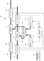
図2は、本発明の第2の実施形態による光増幅装置100の構成を示すブロック図である。光増幅装置100は、2つの光増幅器を有する。2つの光増幅器は、それぞれの利得媒体110および利得媒体111から構成される。利得媒体110および利得媒体111のそれぞれは、エルビウム添加シングルモードファイバで構成されてもよい。光増幅器は、アイソレータ、WDMカプラー、および等化フィルタを備えてもよい。
FIG. 2 is a block diagram showing a configuration of an
利得媒体110は、光ファイバ101を通して供給され、パワーモニタ141を通過した光信号を増幅する。パワーモニタ141は、光ファイバ101からの光の小部分を取りだし、フォトダイオードを用いてそれを電気モニタ信号に変換する。典型的には、パワーモニタ141は、生成した電気モニタ信号によって入ってくる光パワーをモニタするために、利得媒体110に入力される光の1%を取り出すこととしてもよい。同様に、パワーモニタ148は、利得媒体110の出力光パワーに応じた電気モニタ信号を生成する。利得媒体110によって増幅され、モニタ148によってモニタされた光信号は、光ファイバ108に出力される。
The
同じように、利得媒体111は、光ファイバ102から入力され、パワーモニタ142によってモニタされた光信号を増幅する。利得媒体111によって増幅された光信号は、パワーモニタ149によってモニタされ、光ファイバ109に出力される。
Similarly, the
それぞれの利得媒体110および利得媒体111による光増幅のための励起光は、それぞれのファイバ133およびファイバ134を通して供給される。励起光は、可変結合装置130から出力される。可変結合装置130は、それぞれのファイバ133およびファイバ134が接続される2つの入力ポートを有する。ファイバ131およびファイバ132は、それぞれの励起レーザー120および励起レーザー121の出力に接続される。
The excitation light for optical amplification by the
それぞれのファイバ131、132、133、および134におけるそれぞれの光パワーは、P131、P132、P133、およびP134と表される。可変結合装置130の結合係数をCで表わし、透過率をTで表わすと、パワー間の関係は典型的には以下のようになる。
透過率Tは低損失デバイスでは高く、典型的には0.98を上回る。結合係数Cは、可変結合装置130に対して制御され、0と1との間に調整される。パワーP131およびP132は、励起レーザー120および励起レーザー121のそれぞれの出力パワーである。利得媒体110および利得媒体111に供給される励起パワーは、それぞれパワーP133およびP134である。
The transmittance T is high in low-loss devices and typically exceeds 0.98. The coupling coefficient C is controlled with respect to the
制御装置140は、可変結合装置130の結合係数Cだけではなく、励起レーザー120および励起レーザー121も制御する。この制御は、インタフェース150によって提供される増幅器設定パラメータに従って、励起レーザー120および励起レーザー121の動作情報に従って、およびパワーモニタ141、142、148、149によって提供されるパワーモニタ情報に従って行われる。
The
モニタ148およびモニタ149の出力パワーに応じた制御は、2つの利得媒体110および111に対して個別に行われる。励起レーザー120および励起レーザー121の制御は、モニタ値および増幅器設定パラメータに応じて個別に行われる。その結果、励起レーザーの1つがオフにされることがある。この場合、制御装置140は更新された動作値を格納し、オフにされた励起レーザーに対して最後に格納された値に従って制御が実行される。
Control according to the output power of the
あるいは、制御装置140は、インタフェース150によって提供される増幅器設定パラメータに従って、励起レーザー120および励起レーザー121の動作情報に従って、そしてパワーモニタ148およびパワーモニタ149によって提供されるパワーモニタ情報に従って、独自に制御を行うこととしてもよい。この場合、パワーモニタ141およびパワーモニタ142によって提供される情報は、制御のためには使用されない。
Alternatively, the
2つの利得媒体110、111を含み、制御装置140によって制御される2つの増幅器は、典型的には同じ場所に配置されるので、短距離ファイバによって励起パワーを伝送するための損失は無視できる。入力用のそれぞれの光ファイバ101、102、および出力用のそれぞれの光ファイバ108、109を有する2つのファイバは、一方向の態様で構成されることとしてもよい。
Since the two amplifiers, including the two
あるいは、ファイバは双方向の態様で構成されていてもよく、これらのうち光ファイバ101、109はそれぞれ入力用ファイバであり、光ファイバ108、102はそれぞれ出力用のファイバである。この場合、パワーモニタ142は利得媒体111の出力パワーをモニタし、パワーモニタ149は同じ利得媒体への入力パワーをモニタする。利得媒体と、アイソレータやWDMカプラーなどのそれに取り付けられた構成部品は、光信号の伝搬方向に従って構成される。
Alternatively, the fibers may be configured in a bidirectional manner, of which the
制御装置140による制御に応じて、励起レーザー120および励起レーザー121の励起光は、可変結合装置130によって分けられる。励起レーザー120および励起レーザー121の出力は、励起レーザー120および励起レーザー121の最小電力消費に向けて設定される。
The excitation light of the
制御装置140による制御によれば、利得媒体110および利得媒体111による増幅のために、必要以上の励起パワーを用いることはない。このような制御は、光ファイバ101および光ファイバ102の入力信号が低減したとき、または必要な出力パワーが増加したときでも有効である。
According to the control by the
本実施形態によれば、利得媒体110、111を有する2つの光増幅器の電力消費は、増幅器の耐用期間の間に低減する。電力消費の低減は、これらの増幅器が異なる帯域幅で使用される場合、またはネットワークの耐用期間にわたって帯域幅が変化する場合に、必要な光励起パワーの相違の原因となるシステムの経年劣化に対して効果がある。
According to this embodiment, the power consumption of the two optical amplifiers having the
図2に示した構成において、励起レーザー120および励起レーザー121はそれぞれ同一種類のレーザーである。それらの特性は類似している。利得媒体110および利得媒体111に必要な合計の励起パワーが中程度である場合、制御装置140はいずれかをオフにし、他方を使用して総励起パワーを生成し、利得媒体110と利得媒体111との間で励起光を適切に分けるように可変結合装置130を構成する。例えば、励起レーザー120がオンであり、励起レーザー121がオフとなる。レーザー120の特性が経年劣化によって低下した場合、使用されていないレーザー121の効率の方が優れることになる。その結果、制御装置140は徐々にレーザー121をオン状態とし、レーザー121からのより多くのパワーを用いる。それらの相対的な効率、および利得媒体110と利得媒体111に対して必要な励起パワーに応じて、励起レーザー120をオフとしてもよいし、レーザー121によってのみ励起パワーを生成することとしてもよい。制御装置140は、可変結合装置130を適切に制御する。
In the configuration shown in FIG. 2, the
あるいは、励起レーザー120は、非常に高い励起パワーを出力することができるレーザーであり、励起レーザー121は、中程度のレーザーパワーだけを出力することができるレーザーである。すなわち、励起レーザー120と励起レーザー121は複数種類のレーザーであり、異なる仕様を有する。例えば、レーザー120は冷却された励起レーザーであってもよく、レーザー121は冷却されていない励起レーザーであってもよい。パッケージおよびチップ構造に応じて、レーザー121の効率はよくなる。
Alternatively, the
利得媒体110および利得媒体111によって増幅される光信号の帯域幅が制限されている場合、低い励起パワーだけが必要となる。この場合、制御装置140は励起レーザー121のみをオンとし、励起レーザー120はオフにされる。可変結合装置130は、制御装置140によって適切に構成される。
If the bandwidth of the optical signal amplified by the
増幅される光信号の帯域幅が拡大すると、より多くの励起パワーが必要となる。励起レーザー121のパワーが限界に達し、したがって効率がゼロになった場合、制御装置140はより多くの励起パワーを供給するために励起レーザー120をオンにし、励起レーザー120および励起レーザー121を最小電力消費設定に設定し、可変結合装置130の結合係数を適切に調整する。
As the bandwidth of the amplified optical signal increases, more excitation power is required. When the power of the
図2に示した構成において、利得媒体110および利得媒体111を有する増幅器は、自動パワー制御方式で用いられる。制御装置140による制御は、インタフェース150によって提供される増幅器設定パラメータに従い、励起レーザー120および励起レーザー121の動作情報に従い、そしてパワーモニタ148およびパワーモニタ149によって提供されるパワーモニタ情報に従って行われる。パワーモニタ141およびパワーモニタ142によって提供される情報は使用されない。
In the configuration shown in FIG. 2, the
あるいは、利得媒体110および利得媒体111を有する増幅器は、自動ゲイン制御方式で用いられる。制御装置140による制御は、インタフェース150によって提供される増幅器設定パラメータに従い、励起レーザー120および励起レーザー121の動作情報に従い、そしてパワーモニタ141、142、148、および149によって提供されるパワーモニタ情報に従って行われる。パワーモニタ141のパワーモニタ148に対する比率についての情報は、利得媒体110による利得に関する情報を提供する。同じように、パワーモニタ142のパワーモニタ149に対する比率についての情報は、利得媒体111による利得に関する情報を提供する。
Alternatively, the amplifier having the
あるいは、利得媒体110および利得媒体111を含む増幅器は、自動電流制御方式で用いられる。制御装置140による制御は、インタフェース150によって提供される増幅器設定パラメータに従い、そして励起レーザー120および励起レーザー121の動作情報に従って行われる。パワーモニタ141、142、148、および149によって提供される情報は、制御には使用されない。増幅の目標値は、励起レーザー120および励起レーザー121の駆動電流の合計を用いて設定される。
Alternatively, the amplifier including the
あるいは、増幅の目標値は、結合係数Cとその補完である(1−C)を考慮して、励起レーザー120および励起レーザー121の駆動電流の合計を用いて設定される。
Alternatively, the amplification target value is set using the sum of the drive currents of the
Nを正の整数としたときの2N個の増幅器を制御する場合、図2に示した構成を並列して用いることができることは明らかである。この場合、それぞれが図2に記載した装置と同様であるN個の増幅システムが用いられる。 When controlling 2N amplifiers when N is a positive integer, it is clear that the configurations shown in FIG. 2 can be used in parallel. In this case, N amplification systems, each similar to the apparatus described in FIG. 2, are used.
図3は、図2に示した可変結合装置130として用いることができる可変光カプラー200の構成を示すブロック図である。可変光カプラー200は、2つの入力ファイバ201および202と、2つの出力ファイバ203および204を有する。可変光カプラー200は、そのコアがエバネッセント結合しうる2本の結合ファイバ210および211を備える。
FIG. 3 is a block diagram showing a configuration of a variable
結合係数は、外部信号によって作動する制御器220によって調整される。可変光カプラー200が図2に示した可変結合装置130として用いられる場合、制御器220は図2の制御装置140によって作動させられる。制御器220は、結合ファイバ210および211を変位させるステップモータによって構成することができる。このようなファイバは典型的には0.1dBのオーダの非常に低い挿入損失を有する。結合係数の制御は、結合係数を変更する場合のみに、非常に低い電力消費を必要とする。
The coupling coefficient is adjusted by a
図4は、図2に示した可変結合装置130として用いることができる可変結合器300の構成を示すブロック図である。可変結合器300は、偏光ビーム結合器310、偏光制御器311、および偏光ビームスプリッタ312を有する。可変結合器300は、偏光ビーム結合器310の入力である2つの入力ファイバ301と302とを有する。可変結合器300は、偏光ビームスプリッタ312の出力ファイバである2本の出力ファイバ303と304とを有する。
FIG. 4 is a block diagram showing a configuration of a
2つの直線偏光は、偏光ビーム結合器310によって直交して結合される。可変結合器300が図2に示した可変結合装置130として用いられる場合、入力ファイバ301と302は偏波保持ファイバであり、そのため励起レーザー120と励起レーザー121の直線偏光出力は保持され、その後に結合される。可変結合器300の結合係数は、外部信号によって作動させられる偏光制御器311によって調整される。可変結合器300が図2に示した可変結合装置130として用いられる場合、偏光制御器311は図2の制御装置140によって作動させられる。偏光制御器311は、偏光ビーム結合器310の出力光の偏光を、偏光ビームスプリッタ312の軸に対して回転させる。その結果、2つの入力光を結合させた結果生じる光は、偏光ビームスプリッタ312の2つの直交偏光軸上にマッピングされる。
The two linearly polarized lights are orthogonally coupled by the
図5は、マッハ・ツェンダー干渉計400の構成を示すブロック図であり、マッハ・ツェンダー干渉計400は図2に示した可変結合装置130として用いることができる。マッハ・ツェンダー干渉計400は、2つの入力ファイバ401、402と、強め合う干渉および弱め合う干渉の出力が伝搬する2つの出力ファイバ403、404を有する。マッハ・ツェンダー干渉計400は、干渉計構造410、および干渉計構造410の片方のアームに配置されたヒータ411を有する。干渉計構造410は、挿入損失を低減するために、ファイバで作られたものでもよい。結合係数は制御器412によって調整される。制御器412は、外部信号によって作動させられ、それに応じてヒータ411を制御する。ヒータ411の設定に応じて、干渉計構造410の両アーム間に位相差が現れる。
FIG. 5 is a block diagram showing the configuration of the Mach-
マッハ・ツェンダー干渉計400が図2に示した可変結合装置130として用いられる場合、制御器412は図2の制御装置140によって作動させられる。この場合、励起レーザー120および励起レーザー121は、それらの波長が互いに異なるように選択される。制御を容易にするために、波長間隔が干渉計のフリースペクトルレンジの半分より大きくなるように波長を設定することができる。ヒータ411によって調整された位相差に応じて、2つの入力パワーの結合されたものが、強め合う干渉出力として出力ファイバ403を通して出力され、その相補成分が弱め合う干渉出力として出力ファイバ404を通して出力される。
When the Mach-
図6は、図2に示した励起レーザー120および励起レーザー121のいずれかとして用いることができるレーザー装置500の構成を示すブロック図である。レーザー装置500は、2つの励起レーザーダイオード520および521を有する。励起レーザーダイオード520および励起レーザーダイオード521の出力光は、偏光ビーム結合器522によって結合され、ファイバ530を通して出力される。制御器510は、外部信号に従って励起レーザーダイオード520および励起レーザーダイオード521の両方の出力を制御し、励起レーザーダイオード520および励起レーザーダイオード521のモニタ値を外部制御システムに戻す。
FIG. 6 is a block diagram showing a configuration of a
制御器510および偏光ビーム結合器522だけでなく、励起レーザーダイオード520、521もパッケージ501に集積することとしてもよい。レーザー装置500が図2に示した励起レーザー120として用いられる場合、制御器510は、図2の制御装置140による制御に従って励起レーザーダイオード520および励起レーザーダイオード521の両方を駆動する。このようにして、冗長構成とした励起レーザーダイオードを本実施形態における単一のレーザーとして制御することができ、これによって図2の光増幅装置100の信頼性も高められる。
Not only the
図7は、図2に示した可変結合装置130だけではなく励起レーザー120および励起レーザー121の代わりにも用いることができる励起装置600の構成を示すブロック図である。励起装置600は、2つのレーザーダイオードチップ610、611、および可変結合装置620を有する。励起装置600は、パッケージ603内に取り付けられる。励起装置600は、2つの出力601、602を備え、これらが可変結合装置620の出力である。
FIG. 7 is a block diagram showing a configuration of an
レーザーダイオードチップ610およびレーザーダイオードチップ611は外部制御システムによって駆動される。レーザーダイオードチップ610およびレーザーダイオードチップ611の駆動条件は、外部制御システムによって設定される。可変結合装置もまた、励起装置600の外部から制御される。例えば、可変結合装置620は可変カプラーで実現することができるが、可変カプラーはレーザーダイオードチップ610およびレーザーダイオードチップ611と集積することができ、外部制御システムからの電流によって作動させられる。
The
励起装置600が、図2の可変結合装置130だけでなく励起レーザー120および励起レーザー121の代わりに用いられる場合、可変結合装置620だけでなくレーザーダイオードチップ610およびレーザーダイオードチップ611も、制御装置140によって同じように制御される。レーザーダイオードチップ610およびレーザーダイオードチップ611の駆動状態は、制御装置140によってモニタされる。励起装置600を用いることにより、増幅器を制御することによる電力削減に加えて、集積化によるコスト低減を図ることができる。
When the
上述したように、本実施形態の光増幅装置100によれば、複数の光増幅器の間で必要な励起パワーに相違がある場合であっても、複数の光増幅器の電力消費を低減することができる。
<第3の実施形態>
As described above, according to the
<Third embodiment>
次に、本発明の第3の実施形態について説明する。図8は、本発明の第3の実施形態による光増幅装置700の構成を示すブロック図である。
Next, a third embodiment of the present invention will be described. FIG. 8 is a block diagram showing a configuration of an
光増幅装置700は、710、711、712、および713と表示された4つの受動利得ブロックを有する。これらの受動利得ブロック710から713のそれぞれは、利得媒体110が図2に示したパワーモニタ141および148と集積された装置と同様である。受動利得ブロックのそれぞれは、シングルモードファイバ入力とシングルモードファイバ出力を有する。各受動利得ブロックのパワーモニタは制御装置740に備えられている。
The
制御装置740は、制御装置140と同様の態様で制御を実行する。しかしながら、制御装置740はより多くの受動利得ブロック、励起レーザー、および可変結合装置とともに動作するように構成されている。制御装置740は、受動利得ブロック710から713を用いる増幅器を設定するためのパラメータをも所持している。
The
受動利得ブロック710および711に対する光励起は、可変結合装置732の2つの出力によって提供される。受動利得ブロック712および713に対する光励起は、可変結合装置733の2つの出力によって提供される。可変結合装置732の2つの入力は、可変結合装置730の1つの出力と可変結合装置731の1つの出力に接続されている。可変結合装置733の2つの入力は、可変結合装置730の1つの出力と可変結合装置731の1つの出力に接続されている。可変結合装置730の2つの入力は、励起レーザー720および721に接続されている。可変結合装置731の2つの入力は、励起レーザー722および723に接続されている。
Photoexcitation to the passive gain blocks 710 and 711 is provided by the two outputs of the
励起レーザー720から723は、図2に示した励起レーザー120および121と同じである。可変結合装置730から733は、図2の可変結合装置130と同じである。
The
制御装置740は、可変結合装置730から733の結合係数Cだけでなく、励起レーザー720から723も制御する。この制御は、制御装置740の内部に備えられた増幅器設定パラメータに従い、励起レーザー720から723の動作情報に従い、そして受動利得ブロック710から713によって提供されるパワーモニタ情報に従って実行される。出力パワーに応じた制御は、4つの受動利得ブロック710から713に対して個別に実行される。
The
励起レーザー720から723の制御は、モニタ値および増幅器設定パラメータに応じて個別に行われる。励起レーザーの少なくとも1つはオフにされてもよい。この場合、制御装置740は更新された動作値を格納し、オフにされた励起レーザーに対して最後に格納された値に従って制御を行う。
The control of the
4つの励起レーザー720から723の励起光は、可変結合装置の2x2の交差構造によって、4つの受動利得ブロック710から713のそれぞれに分配される。図8に記載したものと同じ構造を、2N個の受動利得ブロックに適用することができる。ここで、Nは正の整数であり、2N個のレーザーと、N個の可変結合装置をN列に格子状に構成したN2個の可変結合装置とを有する。
The excitation light of the four
あるいは、コスト低減のために、励起レーザー720から723のうち最大3個のレーザーを、図8に示した構成から取り除いてもよい。この場合、このような構成としても、4個の受動利得ブロック710から713に対して励起光を正しく提供することが可能である。
Alternatively, for cost reduction, up to three of the
制御装置740による制御に従って、励起レーザー720から723の励起光は、可変結合装置によって分けられる。励起レーザー720から723の各出力は、励起レーザーの電力消費が最小になるように設定される。
According to the control by the
制御装置740による制御によれば、受動利得ブロック710から713の増幅のために、必要以上の励起パワーを必要としない。入力光ファイバの入力信号が減少したとき、または必要な出力パワーが増加したときでも、このような制御は有効である。
According to the control by the
本実施形態の光増幅装置700によれば、受動利得ブロックを含む4つの光増幅器の電力消費が、増幅器の耐用期間の間に低減する。電力消費の低減は、増幅器が種々の帯域幅で使用される場合、または帯域幅がネットワークの耐用期間にわたって変化する場合に、必要な光励起パワーの相違の原因となるシステムの経年劣化に対して有効である。
According to the
上述したように、本実施形態の光増幅装置700によれば、複数の光増幅器の間で必要な励起パワーに相違がある場合であっても、複数の光増幅器の電力消費を低減することができる。
<第4の実施形態>
As described above, according to the
<Fourth Embodiment>
次に、本発明の第4の実施形態について説明する。図9は、本発明の第4の実施形態による光増幅装置800の構成を示すブロック図である。
Next, a fourth embodiment of the present invention will be described. FIG. 9 is a block diagram showing a configuration of an
光増幅装置800は、C01からC07と表示された7コアを備えたマルチコアエルビウム添加ファイバ(MC−EDF)810を有する。各コアは、個別の利得媒体であり、同じファイバ810に含まれる。入力信号は、コアC01からC07に対して801から807と表示されている。それぞれの出力信号は891から897と表示されている。
The
7コアを有するパワーモニタ841は、MC−EDF810への入力信号のパワーを個別にモニタする。モニタ信号は、パワーモニタ841によって入力コア毎に個別に生成される。7コアを有するパワーモニタ842は、MC−EDF810からの出力信号のパワーを個別にモニタする。モニタ信号は、パワーモニタ842によって出力コア毎に個別に生成される。パワーモニタの情報は、制御装置840に提供される。
The
制御装置840は、図8に示した制御装置740と同様の方法で制御を実行するが、より多くの利得ブロック、励起レーザー、および可変結合装置と共に動作するように構成されている。制御装置840は、コアC01からC07を含む増幅器を設定するためのパラメータも所持している。
The
MC−EDF810は個別コア励起方式で励起される。コアC01からC07の光励起は、可変結合装置833、834、835、および836によって提供される。他の3つの可変結合装置830から832は、820から822と表示された3つの励起レーザーによって生成された励起光を結合して分配するために、可変結合装置833から836と組み合わせて用いられる。
The MC-EDF810 is excited by an individual core excitation method. Photoexcitation of cores C01 to C07 is provided by
各励起レーザーは、可変結合装置の入力に接続される。各可変結合装置830、832および833は、励起レーザーまたは他の可変結合装置の出力のいずれかに接続される2つの入力ポートを有する。各可変結合装置831、834、835、および836は、励起レーザーまたは別の可変結合装置の出力のいずれかに接続される1つの入力ポートを有しているが、他方の入力ポートは非接続のままである。830から836と表示された可変結合装置の各出力ポートは、MC−EDF810のコアまたは別の可変結合装置の入力ポートのいずれかに接続される。
Each excitation laser is connected to the input of a variable coupling device. Each
ここで、励起レーザーの個数(3)は1より大きいが、個々の利得媒体の個数(7)よりも小さい。可変結合装置の個数(7)は利得媒体の個数の半分(3.5)より大きいが、その二乗(49)よりは小さい。 Here, the number of excitation lasers (3) is greater than 1, but smaller than the number of individual gain media (7). The number of variable coupling devices (7) is larger than half the number of gain media (3.5), but smaller than its square (49).
制御装置840は、830から836と表示された可変結合装置の結合係数Cだけでなく、820から822と表示された励起レーザーも制御する。この制御は、制御装置840に内部に備えられた増幅器設定パラメータに従い、励起レーザー820から822の動作情報に従い、そして、パワーモニタ841および842によって提供されるパワーモニタ情報に従って実行される。MC−EDF810の7個の利得媒体C01からC07に対して、出力パワーに応じた制御が個別に行われる。820から822と表示された励起レーザーの制御は、モニタ値および増幅器設定パラメータに応じて個別に行われる。励起レーザーの少なくとも1つはオフにされてもよい。この場合、制御装置840は更新された動作値を格納し、オフにされる励起レーザーに対して最後に格納された値に従って制御を実行する。
The
制御装置840による制御に応じて、820から822と表示された励起レーザーの励起光は、可変結合装置によって分けられる。励起レーザー820から822の出力は、励起レーザーの最小電力消費に設定される。制御装置840による制御によれば、MC−EDF810のコアC01からC07の増幅のために、必要以上の励起パワーを必要としない。入力ファイバの入力信号が減少したとき、または必要な出力パワーが増加したときでも、このような制御は有効である。
Depending on the control by the
本実施形態によれば、MCF光増幅器の電力消費が、増幅器の耐用期間の間に低減する。電力消費の低減は、増幅器が種々の帯域幅で使用される場合、またはネットワークの耐用期間にわたって帯域幅が変化する場合に、必要な光励起パワーの相違の原因となるシステムの経年劣化に対して有効である。 According to this embodiment, the power consumption of the MCF optical amplifier is reduced during the useful life of the amplifier. Reduced power consumption is effective against aging of the system, which causes differences in the required photoexcited power when the amplifier is used in different bandwidths or when the bandwidth changes over the life of the network. Is.
上述したように、本実施形態の光増幅装置800によれば、複数の光増幅器の間で必要な励起パワーに相違がある場合であっても、複数の光増幅器の電力消費を低減することができる。
<第5の実施形態>
As described above, according to the
<Fifth Embodiment>
次に、本発明の第5の実施形態について説明する。図10は、本発明の第5の実施形態による光増幅装置900の構成を示すブロック図である。
Next, a fifth embodiment of the present invention will be described. FIG. 10 is a block diagram showing a configuration of an
光増幅装置900は、910および911と表示された2個のマルチコアエルビウム添加ファイバ(MC−EDF)を有する。例えば、MC−EDFは10個のコアを有することとしてもよい。MC−EDF910および911は、入力信号と出力信号のパワーを個別にモニタするマルチコア・パワーモニタを備える。パワーモニタに関する情報は制御装置940に提供される。制御装置940は、第4の実施形態の制御装置840と同様の方法で制御を実行する。
The
MC−EDF910および911は、共通クラッド励起方式で励起される。クラッド励起のためのマルチモード光励起は、可変結合装置930によって提供される。可変結合装置930は、マルチモード励起レーザー920および921に接続される2つの入力ポートを備える。
MC-EDF910 and 911 are excited by a common clad excitation method. Multimode photoexcitation for clad excitation is provided by the
制御装置940は、可変結合装置930の結合係数Cだけでなく、マルチモード励起レーザー920および921も制御する。この制御は、制御装置940の内部に備えられた増幅器設定パラメータに従い、マルチモード励起レーザー920および921に関する動作情報に従い、そしてMC−EDF910および911内に集積されたパワーモニタによって提供されるパワーモニタ情報に従って実行される。出力パワーに応じた制御が、MC−EDF910および911に対して実行される。
The
マルチモード励起レーザー920および921の制御は、モニタ値および増幅器設定パラメータに応じて個別に行われる。したがって、マルチモード励起レーザーの1つはオフにされてもよい。この場合、制御装置940は更新された動作値を格納し、オフにされたマルチモード励起レーザーに対して最後に格納された値に従って制御を行う。制御装置940による制御によれば、マルチモード励起レーザー920および921の励起光は、可変結合装置930によって分けられ、マルチモード励起レーザー920および921の出力は、マルチモード励起レーザーの電力消費が最小になるように設定される。
Control of the
本実施形態の光増幅装置900によれば、上述した実施形態と同様に、複数の光増幅器の間で必要な励起パワーに相違がある場合であっても、複数の光増幅器の電力消費を低減することができる。
<第6の実施形態>
According to the
<Sixth Embodiment>
次に、本発明の第6の実施形態について説明する。本実施形態では、第2の実施形態による図2の光増幅装置100の動作例を、図11に示したフローチャートを参照して説明する。
Next, a sixth embodiment of the present invention will be described. In the present embodiment, an operation example of the
図11は、光増幅装置100を用いた光信号増幅方法を示すフローチャートである。
FIG. 11 is a flowchart showing an optical signal amplification method using the
制御装置140は、まず、パワーモニタ148、149によって提供されるモニタ情報を用い、それらのモニタ情報を、インタフェース150によって提供される自動パワー制御目標とそれぞれ比較する。制御装置140は、両方のパワーモニタに対して、モニタされたパワーの目標パワーに対する比率を算出する(ステップ1001)。
The
2つの算出された比率が等しい場合(ステップ1001/Yes)、制御装置140はステップ1003に直接進む。算出された比率が等しくない場合(ステップ1001/No)、制御装置140は、比率を等しくするために、可変結合装置130の結合係数Cを制御する(ステップ1002)。この時点では、比率が等しいかどうかをさらにチェックする必要はなく、制御装置140はステップ1003に直接進むことができる。パワー制御目標の1つがゼロである場合、ゼロでない目標を有するパワーモニタに基づいて、制御後にC=0およびC=1である結合係数の値だけが可能である。
If the two calculated ratios are equal (
制御装置140は、その電力消費効率に応じて励起レーザー120および121をランク付けする(ステップ1003)。この効率は、励起レーザー120および121内に集積されたモニタフォトダイオードにより制御装置140に提供されたモニタ出力パワーの、励起レーザー120および121に供給される駆動動作電流に対する比率として算出されることとしてもよい。あるいは、モニタ出力パワーを動作電流と励起電流の合計で、またはそれらの二乗値の合計で割ることによって、励起レーザーに対してこの比率を算出することとしてもよい。
The
オフにされた励起レーザーに対しては、励起レーザーの最後の動作値の保存されている値を用いて、効率を算出する。その結果、励起レーザー120および121の1つが最も高いランクを有し、他の1つが低いランクを有することになる。
For the excited laser turned off, the stored value of the last operating value of the excited laser is used to calculate the efficiency. As a result, one of the
次に、パワーモニタ148によって提供されたモニタパワー情報を、インタフェース150によって提供されるその目標値と比較する(ステップ1004)。モニタ値が目標値よりも大きい場合(ステップ1004/Yes)、効率が最も低い励起レーザーにより出力されるパワーを低下させる(ステップ1005)。最も低いランクの励起レーザーの動作電流がゼロに達した場合、それはオフにされ、その最後の効率値は制御装置140に記憶される。ランクが最も低い励起レーザーが既にオフになっている場合、代わりに次に高いランクのレーザーを制御して、その出力パワーを低下させる。
Next, the monitor power information provided by the
次に、パワーモニタ148によって提供されたモニタパワー情報を、インタフェース150によって提供されるその目標値と再び比較する(ステップ1006)。モニタ値が目標値より小さい場合(ステップ1006/Yes)、最も効率が高い励起レーザーにより出力されるパワーを増加させる(ステップ1007)。最高ランクの励起レーザーの動作電流が上限に達した場合、代わりに次に高いランクのレーザーを制御して、その出力パワーを増加させる。
The monitor power information provided by the
次に、パワーモニタ148によって提供されたモニタパワー情報を、インタフェース150によって提供されたその目標値と再び比較する(ステップ1008)。両者の値が等しい場合(ステップ1008/Yes)、制御ループはステップ1001に戻る。両者の値が等しくないか、または許容範囲外である場合(ステップ1008/No)、制御ループはステップ1004に戻る。
The monitor power information provided by the
このようにして、図2の制御装置140は、3つのパラメータ、すなわち、可変結合装置130の結合係数C、励起レーザー120の出力、および励起レーザー121の出力を、2つのパワーモニタ148および149に従って制御することができる。これにより、パワーモニタ148および149の出力の目標値と実際の値だけを用いているにもかかわらず、電力消費の低減を実現し維持することができる。
In this way, the
上記の説明では、励起レーザーの出力パワーを低下させるステップ(ステップ1005)、および励起レーザーの出力パワーを増加させるステップ(ステップ1007)を、モニタパワーの目標パワーに対する比率を算出するステップ(ステップ1001)、およびこの比率を等しくするために結合係数Cを制御するステップ(ステップ1002)の後に実行することとした。しかしながら、出力パワーを低下させるステップ(ステップ1005)および出力パワーを増加させるステップ(ステップ1007)を、比率を算出するステップ(ステップ1001)および結合係数Cを制御するステップ(ステップ1002)の前に実行することとしてもよい。 In the above description, the step of reducing the output power of the excitation laser (step 1005) and the step of increasing the output power of the excitation laser (step 1007) are steps of calculating the ratio of the monitor power to the target power (step 1001). , And the step of controlling the coupling coefficient C to equalize this ratio (step 1002). However, the step of decreasing the output power (step 1005) and the step of increasing the output power (step 1007) are executed before the step of calculating the ratio (step 1001) and the step of controlling the coupling coefficient C (step 1002). You may do it.
図8に示した第3の実施形態による制御装置740に対しても、同様の制御方法を適用することができる。この場合、ステップ1001およびステップ1002は、730から733の各可変結合装置について繰り返される。各可変結合装置について、目標値とモニタ値の比率を、制御される可変結合装置の出力が接続される利得媒体の異なる組と比較する。
The same control method can be applied to the
N個の利得媒体に対して最大でN2個の可変結合装置が存在するため、比較可能な可変結合装置の十分な数のペアが存在する。同じケースでは、励起レーザー120から123の全てがステップ1003でランク付けされる。その結果、4つのランクが作成される。同じモニタ情報を用いて、最高ランクおよび最低ランクのLDを制御することができる。
Since there are up to N 2 variable coupling devices for N gain media, there are a sufficient number of pairs of comparable variable coupling devices. In the same case, all of the excitation lasers 120-123 are ranked in
最高ランクの効率を有するレーザーにより出力される光パワーを増加させ、最低ランクの効率を有するレーザーにより出力される光パワーを同じ比率で低下させる追加ステップを、ステップ1008とステップ1001との間に追加することができる。この追加ステップの効果は、光増幅装置の電力消費の低減を効果的に早めることである。
An additional step was added between
次に、図2の第2の実施形態の光増幅装置100の別の動作例を、図12に示したフローチャートを参照して説明する。
Next, another operation example of the
図12は、光増幅装置100を用いた光信号増幅方法を示すフローチャートである。
FIG. 12 is a flowchart showing an optical signal amplification method using the
まず、ステップ1101は図11のステップ1001と同一である。2つの算出された比率が等しい場合(ステップ1101/Yes)、制御装置140はステップ1103に直接進む。算出された比率が等しくない場合(ステップ1101/No)、制御装置140は、その比率を等しくするために、可変結合装置130の結合係数Cを制御する(ステップ1102)。ステップ1101およびステップ1102は、ステップ1101で算出された比率が等しくなるまで繰り返される。
First,
ステップ1103、1104、1105、1106、および1107は、図11のそれぞれのステップ1003、1004、1005、1005、1006、および1007と同じである。しかしながら、ステップ1105およびステップ1107の後に、制御ループはステップ1101にジャンプする。ステップ1106の後に、制御ループはステップ1101にジャンプする。
このようにして、図2の制御装置140は3つのパラメータ、すなわち、可変結合装置130の結合係数C、励起レーザー120の出力、および励起レーザー121の出力を、2つのパワーモニタ148および149に従って制御することができる。これにより、パワーモニタ148および149の出力の目標値と実際の値だけを用いているにもかかわらず、電力消費の低減を実現し、維持することができる。
In this way, the
図11に示した制御方法と同じく、図12に示した制御方法を、図8、図9、および図10に示した制御装置740、840、および940にそれぞれ適用することができる。
Similar to the control method shown in FIG. 11, the control method shown in FIG. 12 can be applied to the
最高ランクの効率を有するレーザーにより出力される光パワーを増加させ、最低ランクの効率を有するレーザーにより出力される光パワーを同じ比率で低下させる追加ステップを、ステップ1106とステップ1101との間に追加することができる。この追加ステップの効果は、光増幅装置の電力消費の低減を効果的に早めることである。
An additional step was added between
図13Aは、図2の励起レーザー120の電力消費のシミュレーション結果を示す図であり、出力光励起パワーに対してプロットしたものである。しきい値効果が存在することが明らかである。このことは、利得媒体の光励起に必要なハイパワーが達成される前に、ある程度のエネルギーが消費される必要があることを意味している。したがって、いくつかの利得媒体の間で同じレーザーダイオードを共有することにより、光増幅の電力低減がもたらされる。
FIG. 13A is a diagram showing a simulation result of power consumption of the
図13Bは、ネットワークにおけるトラフィックの進展をシミュレーションした結果を示す図である。このシミュレーションにおいては、図8に示した第3の実施形態による光増幅装置700を用いた。
FIG. 13B is a diagram showing the result of simulating the progress of traffic in the network. In this simulation, the
各曲線1211、1212、1213、および1214は、ネットワークの耐用期間の間に各受動利得ブロック710、711、712、および713を通過するトラフィックを表す。最初は、トラフィックは通常程度である。その結果、利用可能なWDM波長の一部のみが受動利得ブロック710を通過する。時間が経過するに従ってトラフィックは増加し、より多くの波長が使用される。すなわち、受動利得ブロック710に加えて、受動利得ブロック711、712、および713によって増幅される波長が徐々に用いられる。
The
図13Cは、図8に示した第3の実施形態による光増幅装置700の電力消費をシミュレーションした結果を示す図である。シミュレーションは、図13Bに示したトラフィック条件の下で行った。
FIG. 13C is a diagram showing the result of simulating the power consumption of the
曲線1223は、図11に記載したものと同様の制御方法によって制御した、図8の光増幅装置に対するシミュレーション結果を示す。比較のために、曲線1221が同じグラフ上にプロットされているが、これは、各受動利得ブロックが専用の励起レーザーを備えている従来の増幅と同一条件の下における電力消費を表わしている。比較のためにまた、曲線1222は、固定比の光カプラーを用いた光増幅器の同一条件の下での電力消費を表す。
曲線1223は曲線1221および1222よりも常に低いことからわかるように、実施形態の光増幅装置によって、光信号が増幅されるファイバ間でトラフィックが変化する場合であっても、ネットワークの耐用期間にわたって光増幅の電力消費を効率よく低減することが可能になる。
<第7の実施形態>
As can be seen from the fact that the
<7th Embodiment>
次に、本発明の第7の実施形態について説明する。図14は、本発明の第7の実施形態による光増幅装置を用いたネットワークシステム1300の構成を示すブロック図である。
Next, a seventh embodiment of the present invention will be described. FIG. 14 is a block diagram showing a configuration of a
ネットワークシステム1300は、トランスポンダが集約されているノード装置を有する。ノード装置1310のトランスポンダは、光信号を波長で多重化し、また4本のファイバ線によって空間的にも多重化しており、トランスポンダが集約されている別のノード装置1311と連結している。ノード装置1310とノード装置1311との間には、エルビウム添加ファイバ増幅器(EDFA)の2つのグループ1321と1322が光ファイバのスパン間に配置されている。
The
EDFA1321および1322のそれぞれは、図8に示した光増幅装置700と同様の構成としてもよい。あるいは、EDFA1321および1322のそれぞれは、図2に示した光増幅装置100を2セット並列に用いるのと同様の構成としてもよい。また、ノード装置1310とノード装置1311の間の光ファイバはマルチコアファイバであり、EDFA1321および1322は、図9に示した光増幅装置800を4セット並列に用いるのと同様の構成としてもよい。あるいは、ノード装置1310とノード装置1311との間の光ファイバはマルチコアファイバであり、EDFA1321および1322は、図10に示した光増幅装置900を2セット並列に用いるのと同様の構成としてもよい。
Each of the
ノード装置1310および1311に集約されているトランスポンダによって伝送されるトラフィックの変動に応じて、EDFA1321、1322、それらの励起レーザー、および可変結合装置の設定が変更される。図11に記載した制御方法に従って、この設定を変更してもよい。あるいは、図12に記載した制御方法に従って、この設定を変更してもよい。ネットワークシステムにおける光増幅の電力消費は、それに応じて低減される。
The settings of EDFA1321, 1322, their excitation lasers, and the variable coupling device are changed according to the fluctuation of the traffic transmitted by the transponders aggregated in the
さらに、EDFA1321とEDFA1322の間の光ファイバの一部は修復やスプライスされることがあるが、それによって、さらなるスパン損失が生じる。この場合、EDFAの設定を、図11または図12に記載した制御方法に従って再び変更することとしてもよい。ネットワークシステムにおける光増幅の電力消費は、それに応じて低減される。 In addition, some of the optical fibers between EDFA1321 and EDFA1322 may be repaired or spliced, resulting in additional span loss. In this case, the EDFA setting may be changed again according to the control method described in FIG. 11 or FIG. The power consumption of optical amplification in network systems is reduced accordingly.
図15は、図14のネットワークシステム1300をセットアップするために必要な時間をシミュレーションした結果を示す図である。このシミュレーションでは、EDFA1321およびEDFA1322のそれぞれは、図8に示した第3の実施形態の光増幅装置700と同様である。セットアップ時間は、ノード装置1310および1311のトランスポンダの波長情報を導入してから、EDFA1321および1322が安定化するまでの経過時間を意味する。
FIG. 15 is a diagram showing the result of simulating the time required to set up the
棒グラフ1410は、EDFA1321および1322を図11に記載した手順によって制御するのに必要な時間を表す。参考のために示した棒グラフ1411は、ネットワークシステムの同じ条件に対して必要となる時間を表すが、この場合のEDFA1321および1322のセットアップ値は、図8の可変結合装置とレーザーダイオードの値を、動作を開始する前に取り得る値にわたってスキャンすることによって決定される。本実施形態によって、ネットワークシステムの増幅器をより迅速に設定することができることがわかる。
上述したように、第7の実施形態による光増幅装置を用いたネットワークシステム1300によれば、いくつかの光増幅器を用いたネットワークの設定時間を短縮することができる。すなわち、ネットワークの設置から光信号の実際の伝送までの時間を短縮することができる。
As described above, according to the
上記の実施形態の一部又は全部は、以下の付記のようにも記載されうるが、以下には限られない。 Some or all of the above embodiments may also be described, but not limited to:
(付記1)複数の光信号を増幅する複数の光増幅手段と、前記複数の光増幅手段のそれぞれは利得媒体を含み、複数のレーザー光を生成する複数のレーザー光生成手段と、結合係数に従って可変的に前記複数のレーザー光を結合し、複数の励起光を出力する少なくとも1つの光結合手段と、前記複数の励起光のそれぞれは前記利得媒体を励起し、前記結合係数と、前記複数のレーザー光生成手段のそれぞれの出力パワーとを制御する制御手段、を有する光増幅装置。 (Appendix 1) A plurality of optical amplification means for amplifying a plurality of optical signals, each of the plurality of optical amplification means includes a gain medium, and a plurality of laser light generation means for generating a plurality of laser lights, according to a coupling coefficient. At least one photocoupling means that variably couples the plurality of laser beams and outputs the plurality of excitation lights, and each of the plurality of excitation lights excites the gain medium, and the coupling coefficient and the plurality of excitation lights. An optical amplification device having a control means for controlling each output power of the laser light generation means.
(付記2)付記1に記載した光増幅装置であって、前記少なくとも1つの光結合手段は、複数の光結合手段を含み、前記制御手段は、前記複数の光結合手段のそれぞれの前記結合係数を制御する。
(Appendix 2) In the optical amplification device according to
(付記3)付記1または2に記載した光増幅装置であって、前記利得媒体は、マルチコアファイバに含まれるコアであり、前記複数のレーザー光生成手段のそれぞれは、前記複数の励起光のそれぞれによって前記利得媒体を直接励起する。
(Appendix 3) In the optical amplification device according to
(付記4)付記1または2に記載した光増幅装置であって、前記利得媒体はマルチコアファイバであり、前記複数のレーザー光生成手段のそれぞれは、前記マルチコアファイバのクラッドを励起することによって前記利得媒体を励起し、前記複数の励起光のそれぞれはマルチモード光である。
(Appendix 4) In the optical amplification device according to
(付記5)付記1から4のいずれか一項に記載した光増幅装置であって、正の整数Nで表される前記複数の光増幅手段の個数、正の整数Mで表される前記少なくとも1つの光結合手段の個数、および、正の整数Lで表される前記複数のレーザー光生成手段の個数は、
(付記6)付記5に記載した光増幅装置であって、L=N=M2/4という関係式が満たされる。 (Supplementary Note 6) The optical amplifying apparatus according to Additional 5, relational expression L = N = M 2/4 is satisfied.
(付記7)付記5に記載した光増幅装置であって、L=N=M/2という関係式が満たされる。 (Appendix 7) The optical amplifier according to Appendix 5, which satisfies the relational expression L = N = M / 2.
(付記8)付記1から7のいずれか一項に記載した光増幅装置であって、前記少なくとも1つの光結合手段は可変光カプラーであり、前記可変光カプラーは、2本の入力ファイバと、2本の出力ファイバと、コアがエバネッセント結合を行うように構成された2本の結合ファイバ、とを有し、前記制御手段は、前記2本の結合ファイバを変位させることによって前記結合係数を制御する。
(Appendix 8) The optical amplification device according to any one of
(付記9)付記1から7のいずれか一項に記載した光増幅装置であって、前記少なくとも1つの光結合手段は、直線偏光を有する前記複数のレーザー光を直交して結合させるように構成された偏光ビーム結合器と、前記偏光ビーム結合器によって出力された光の偏光を回転させるように構成された偏光制御器と、前記偏光制御器によって出力された光を分割するように構成された偏光ビームスプリッタ、とを備え、前記制御手段は、前記偏光制御器を制御することによって前記結合係数を制御する。
(Appendix 9) The optical amplification device according to any one of
(付記10)付記1から7のいずれか一項に記載した光増幅装置であって、前記少なくとも1つの光結合手段はマッハ・ツェンダー干渉計を有し、前記マッハ・ツェンダー干渉計は、干渉計構造と、前記干渉計構造の一方のアームに配置され、前記干渉計構造の両アーム間の位相差を調整するヒータ、とを有し、前記制御手段は、前記ヒータを制御することによって前記結合係数を制御する。
(Appendix 10) The optical amplification device according to any one of
(付記11)付記1から10のいずれか一項に記載した光増幅装置であって、前記複数のレーザー光生成手段のそれぞれは、同一種類のレーザー光源である。
(Appendix 11) The optical amplifier according to any one of the
(付記12)付記1から10のいずれか一項に記載した光増幅装置であって、前記複数のレーザー光生成手段は、複数種類のレーザー光源であり、異なる仕様を有する。
(Appendix 12) The optical amplifier according to any one of
(付記13)複数のレーザー光を生成し、結合係数に従って可変的に前記複数のレーザー光を結合し、複数の励起光を生成し、前記複数の励起光によって、複数の光信号が通過する複数の利得媒体を励起し、前記結合係数と、前記複数のレーザー光のそれぞれの出力パワーとを制御する光信号増幅方法。 (Appendix 13) A plurality of laser lights are generated, the plurality of laser lights are variably coupled according to a coupling coefficient to generate a plurality of excitation lights, and a plurality of optical signals are passed by the plurality of excitation lights. An optical signal amplification method that excites the gain medium of the above and controls the coupling coefficient and the output power of each of the plurality of laser beams.
(付記14)付記13に記載した光信号増幅方法であって、前記結合係数と前記出力パワーとを前記制御することは、前記複数の利得媒体のそれぞれを通過した光信号の出力レベルをモニタし、前記出力レベルの目標値に対する比率を算出し、前記複数の利得媒体のうちの一の利得媒体に対する前記比率を、前記複数の利得媒体のうちの別の利得媒体に対する前記比率と等しくするように、前記結合係数を制御することを含む。 (Appendix 14) In the optical signal amplification method described in Appendix 13, controlling the coupling coefficient and the output power monitors the output level of the optical signal that has passed through each of the plurality of gain media. , The ratio of the output level to the target value is calculated so that the ratio to one gain medium among the plurality of gain media is equal to the ratio to the other gain medium among the plurality of gain media. , Including controlling the coupling coefficient.
(付記15)付記14に記載した光信号増幅方法であって、前記結合係数と前記出力パワーとを前記制御することは、前記複数のレーザー光のそれぞれを生成するための効率を評価し、前記出力レベルが前記目標値よりも大きい場合、前記複数のレーザー光のなかで最低の前記効率を有するレーザー光の光パワーを減少させ、前記出力レベルが前記目標値よりも小さい場合、前記複数のレーザー光のなかで最高の前記効率を有するレーザー光の光パワーを増加させることを含む。 (Appendix 15) In the optical signal amplification method described in Appendix 14, controlling the coupling coefficient and the output power evaluates the efficiency for generating each of the plurality of laser beams, and the above-mentioned When the output level is larger than the target value, the optical power of the laser light having the lowest efficiency among the plurality of laser lights is reduced, and when the output level is smaller than the target value, the plurality of lasers are used. It involves increasing the optical power of the laser beam having the highest efficiency of the light.
(付記16)付記15に記載した光信号増幅方法であって、前記光パワーを減少させること、および前記光パワーを増加させることは、前記比率を算出すること、および前記結合係数を制御することの後に実行される。 (Appendix 16) In the optical signal amplification method according to Appendix 15, reducing the optical power and increasing the optical power means calculating the ratio and controlling the coupling coefficient. Is executed after.
(付記17)付記15に記載した光信号増幅方法であって、前記光パワーを前記減少させること、および前記光パワーを前記増加させることは、前記比率を前記算出すること、および前記結合係数を前記制御することの前に実行される。 (Appendix 17) In the optical signal amplification method according to Appendix 15, reducing the optical power and increasing the optical power means calculating the ratio and determining the coupling coefficient. It is executed before the control.
(付記18)付記13から17のいずれか一項に記載した光信号増幅方法であって、前記複数の利得媒体は、前記複数の利得媒体のそれぞれから出力される出力信号パワーに従って、自動パワー制御方式で制御される。 (Appendix 18) The optical signal amplification method according to any one of the items 13 to 17, wherein the plurality of gain media are automatically controlled according to the output signal power output from each of the plurality of gain media. It is controlled by the method.
(付記19)付記13から17のいずれか一項に記載した光信号増幅方法であって、前記複数の利得媒体は、前記複数の利得媒体のそれぞれに入力される入力信号パワー、および前記複数の利得媒体のそれぞれから出力される出力信号パワーに従って、自動利得制御方式で制御される。 (Appendix 19) The optical signal amplification method according to any one of the items 13 to 17, wherein the plurality of gain media includes input signal power input to each of the plurality of gain media, and the plurality of gain media. It is controlled by an automatic gain control method according to the output signal power output from each of the gain media.
(付記20)付記13から17のいずれか一項に記載した光信号増幅方法であって、前記複数の利得媒体は、前記複数のレーザー光を生成する電流に従って、自動電流制御方式で制御される。 (Supplementary Note 20) The optical signal amplification method according to any one of Supplementary note 13 to 17, wherein the plurality of gain media are controlled by an automatic current control method according to currents that generate the plurality of laser beams. ..
以上、実施形態を参照して本願発明を説明したが、本願発明は上記実施形態に限定されるものではない。本願発明の構成や詳細には、本願発明のスコープ内で当業者が理解し得る様々な変更をすることができる。 Although the invention of the present application has been described above with reference to the embodiment, the invention of the present application is not limited to the above embodiment. Various changes that can be understood by those skilled in the art can be made within the scope of the present invention in terms of the structure and details of the present invention.
10、100、700、800、900 光増幅装置
20 光増幅器
30 レーザー光源
40 光結合装置
50 制御器
101、102、108、109 光ファイバ
110、111 利得媒体
120、121、720から723、820から822 励起レーザー
130、620、730から733、830から836、930 可変結合装置
131、132、133、134、530 ファイバ
140、740、840、940 制御装置
141、142、148、149、841、842 パワーモニタ
150 インタフェース
200 可変光カプラー
201、202、301、302、401、402 入力ファイバ
203、204、303、304、403、404 出力ファイバ
210、211 結合ファイバ
220、412 制御器
300 可変結合器
310 偏光ビーム結合器
311 偏光制御器
312 偏光ビームスプリッタ
400 マッハ・ツェンダー干渉計
410 干渉計構造
411 ヒータ
500 レーザー装置
501 パッケージ
510 制御器
520、521 励起レーザーダイオード
522 偏光ビーム結合器
600 励起装置
601、602 出力
603 パッケージ
610、611 レーザーダイオードチップ
710、711、712、713 受動利得ブロック
801から807 入力信号
810、910、911 マルチコアエルビウム添加ファイバ
891から897 出力信号
920、921 マルチモード励起レーザー
1300 ネットワークシステム
1310、1311 ノード装置
1321,1322 エルビウム添加ファイバ増幅器
10, 100, 700, 800, 900
Claims (8)
複数のレーザー光を生成する複数のレーザー光生成手段と、
結合係数に従って可変的に前記複数のレーザー光を結合し、複数の励起光を出力する少なくとも1つの光結合手段と、前記複数の励起光のそれぞれは前記利得媒体を励起し、
前記結合係数と、前記複数のレーザー光生成手段のそれぞれの出力パワーとを制御する制御手段、を有し、
前記制御手段は、前記複数のレーザー光生成手段を最小電力消費設定に設定し、前記光結合手段の前記結合係数を調整し、
前記少なくとも1つの光結合手段は可変光カプラーであり、
前記可変光カプラーは、
2本の入力ファイバと、
2本の出力ファイバと、
コアがエバネッセント結合を行うように構成された2本の結合ファイバ、とを有し、
前記制御手段は、前記2本の結合ファイバを変位させることによって前記結合係数を制御する
光増幅装置。 A plurality of optical amplification means for amplifying a plurality of optical signals and each of the plurality of optical amplification means include a gain medium.
Multiple laser light generation means that generate multiple laser lights,
At least one optical coupling means that variably couples the plurality of laser lights according to the coupling coefficient and outputs the plurality of excitation lights, and each of the plurality of excitation lights excites the gain medium.
It has a control means for controlling the coupling coefficient and the output power of each of the plurality of laser light generation means.
The control means sets the plurality of laser light generating means to the minimum power consumption setting, adjusts the coupling coefficient of the optical coupling means, and adjusts the coupling coefficient.
The at least one optical coupling means is a variable optical coupler.
The variable optical coupler
Two input fibers and
Two output fibers and
The core has two coupling fibers, which are configured to make an evanescent coupling, and
The control means controls the coupling coefficient by displacing the two coupling fibers.
Optical amplifier .
複数のレーザー光を生成する複数のレーザー光生成手段と、
結合係数に従って可変的に前記複数のレーザー光を結合し、複数の励起光を出力する少なくとも1つの光結合手段と、前記複数の励起光のそれぞれは前記利得媒体を励起し、
前記結合係数と、前記複数のレーザー光生成手段のそれぞれの出力パワーとを制御する制御手段、を有し、
前記制御手段は、前記複数のレーザー光生成手段を最小電力消費設定に設定し、前記光結合手段の前記結合係数を調整し、
前記少なくとも1つの光結合手段は、
直線偏光を有する前記複数のレーザー光を直交して結合させるように構成された偏光ビーム結合器と、
前記偏光ビーム結合器によって出力された光の偏光を回転させるように構成された偏光制御器と、
前記偏光制御器によって出力された光を分割するように構成された偏光ビームスプリッタ、とを備え、
前記制御手段は、前記偏光制御器を制御することによって前記結合係数を制御する
光増幅装置。 A plurality of optical amplification means for amplifying a plurality of optical signals and each of the plurality of optical amplification means include a gain medium.
Multiple laser light generation means that generate multiple laser lights,
At least one optical coupling means that variably couples the plurality of laser lights according to the coupling coefficient and outputs the plurality of excitation lights, and each of the plurality of excitation lights excites the gain medium.
It has a control means for controlling the coupling coefficient and the output power of each of the plurality of laser light generation means.
The control means sets the plurality of laser light generating means to the minimum power consumption setting, adjusts the coupling coefficient of the optical coupling means, and adjusts the coupling coefficient.
The at least one photocoupling means
A polarized beam coupler configured to orthogonally couple the plurality of laser beams having linearly polarized light,
A polarization controller configured to rotate the polarization of the light output by the polarization beam coupler,
A polarization beam splitter configured to split the light output by the polarization controller.
The control means controls the coupling coefficient by controlling the polarization controller.
Optical amplifier .
前記少なくとも1つの光結合手段は、複数の光結合手段を含み、
前記制御手段は、前記複数の光結合手段のそれぞれの前記結合係数を制御する。 The optical amplifier according to claim 1 or 2.
The at least one photocoupling means includes a plurality of photocoupling means.
The control means controls the coupling coefficient of each of the plurality of optical coupling means.
前記利得媒体は、マルチコアファイバに含まれるコアであり、
前記複数のレーザー光生成手段のそれぞれは、前記複数の励起光のそれぞれによって前記利得媒体を直接励起する。 The optical amplifier according to any one of claims 1 to 3.
The gain medium is a core contained in a multi-core fiber, and is a core.
Each of the plurality of laser light generating means directly excites the gain medium by each of the plurality of excitation lights.
前記利得媒体はマルチコアファイバであり、
前記複数のレーザー光生成手段のそれぞれは、前記マルチコアファイバのクラッドを励起することによって前記利得媒体を励起し、
前記複数の励起光のそれぞれはマルチモード光である。 The optical amplifier according to any one of claims 1 to 3.
The gain medium is a multi-core fiber.
Each of the plurality of laser light generating means excites the gain medium by exciting the cladding of the multi-core fiber.
Each of the plurality of excitation lights is multimode light.
正の整数Nで表される前記複数の光増幅手段の個数、正の整数Mで表される前記少なくとも1つの光結合手段の個数、および、正の整数Lで表される前記複数のレーザー光生成手段の個数は、
The number of the plurality of optical amplification means represented by the positive integer N, the number of the at least one optical coupling means represented by the positive integer M, and the plurality of laser beams represented by the positive integer L. The number of generation means is
L=N=M2/4という関係式が満たされる。 The optical amplifier according to claim 6.
L = N = M relational expression 2/4 is satisfied.
L=N=M/2という関係式が満たされる。 The optical amplifier according to claim 6.
The relational expression L = N = M / 2 is satisfied.
Applications Claiming Priority (1)
| Application Number | Priority Date | Filing Date | Title |
|---|---|---|---|
| PCT/JP2017/015919 WO2018193587A1 (en) | 2017-04-20 | 2017-04-20 | Optical amplifying apparatus and method of amplifying optical signal |
Publications (2)
| Publication Number | Publication Date |
|---|---|
| JP2020513162A JP2020513162A (en) | 2020-04-30 |
| JP6962384B2 true JP6962384B2 (en) | 2021-11-05 |
Family
ID=63855754
Family Applications (1)
| Application Number | Title | Priority Date | Filing Date |
|---|---|---|---|
| JP2019555985A Active JP6962384B2 (en) | 2017-04-20 | 2017-04-20 | Optical amplifier and optical signal amplification method |
Country Status (4)
| Country | Link |
|---|---|
| US (1) | US11374377B2 (en) |
| EP (1) | EP3613112A4 (en) |
| JP (1) | JP6962384B2 (en) |
| WO (1) | WO2018193587A1 (en) |
Families Citing this family (3)
| Publication number | Priority date | Publication date | Assignee | Title |
|---|---|---|---|---|
| US20210249834A1 (en) * | 2018-06-28 | 2021-08-12 | Nec Corporation | Light source device and optical amplifier |
| BR112022005222A2 (en) * | 2019-09-19 | 2022-08-16 | Ofs Fitel Llc | O-BAND PARALLEL AMPLIFIER |
| CN117375724B (en) * | 2023-12-06 | 2024-03-19 | 华海通信技术有限公司 | Underwater equipment and communication system |
Family Cites Families (16)
| Publication number | Priority date | Publication date | Assignee | Title |
|---|---|---|---|---|
| JPH043029A (en) * | 1990-04-20 | 1992-01-08 | Fujitsu Ltd | Method for driving pumping light source for optical amplification |
| JP3137391B2 (en) | 1991-11-08 | 2001-02-19 | ケイディディ株式会社 | Fiber optical amplifier |
| US5546484A (en) * | 1994-10-14 | 1996-08-13 | Kaptron, Inc. | Fiber optic switch using polished-type directional coupler |
| US5740288A (en) * | 1995-02-22 | 1998-04-14 | E-Tek Dynamics, Inc. | Variable polarization beam splitter, combiner and mixer |
| US6603596B2 (en) * | 1998-03-19 | 2003-08-05 | Fujitsu Limited | Gain and signal level adjustments of cascaded optical amplifiers |
| JP4003029B2 (en) * | 1999-07-22 | 2007-11-07 | 村田機械株式会社 | Automatic warehouse |
| JP3949503B2 (en) | 2002-04-23 | 2007-07-25 | 古河電気工業株式会社 | Optical amplifier and optical communication system using the amplifier |
| US8233214B2 (en) * | 2008-02-13 | 2012-07-31 | Maxim Bolshtyansky | Optical fiber amplifier and a control method therefor |
| EP2131509B1 (en) | 2008-06-06 | 2014-08-06 | Xieon Networks S.à.r.l. | Optical amplifier arrangement |
| US9083142B2 (en) | 2010-10-22 | 2015-07-14 | Nec Corporation | Excitation light distribution device, excitation light distribution method, optical amplification system and node device |
| JP5767147B2 (en) * | 2011-11-07 | 2015-08-19 | 日本電信電話株式会社 | Optical amplifier system and optical amplification method |
| JP6102943B2 (en) * | 2012-12-13 | 2017-03-29 | 富士通株式会社 | Optical device |
| JP2015167158A (en) * | 2014-03-03 | 2015-09-24 | 日本電信電話株式会社 | multi-core fiber amplifier |
| JP5728614B1 (en) | 2014-09-24 | 2015-06-03 | 株式会社石原産業 | Optical coupler and optical branching method using the optical coupler |
| EP3029860A1 (en) | 2014-12-05 | 2016-06-08 | Alcatel Lucent | Optical amplification system |
| CN108141283B (en) * | 2015-09-29 | 2020-07-28 | 日本电气株式会社 | Optical repeater and control method of optical repeater |
-
2017
- 2017-04-20 US US16/606,290 patent/US11374377B2/en active Active
- 2017-04-20 EP EP17906389.6A patent/EP3613112A4/en active Pending
- 2017-04-20 WO PCT/JP2017/015919 patent/WO2018193587A1/en unknown
- 2017-04-20 JP JP2019555985A patent/JP6962384B2/en active Active
Also Published As
| Publication number | Publication date |
|---|---|
| US11374377B2 (en) | 2022-06-28 |
| WO2018193587A1 (en) | 2018-10-25 |
| US20210194218A1 (en) | 2021-06-24 |
| JP2020513162A (en) | 2020-04-30 |
| EP3613112A1 (en) | 2020-02-26 |
| EP3613112A4 (en) | 2020-04-22 |
Similar Documents
| Publication | Publication Date | Title |
|---|---|---|
| US11463190B2 (en) | Optical repeater and control method for optical repeater | |
| JP7160680B2 (en) | Optical amplifier, optical network, and amplification method | |
| JP6962384B2 (en) | Optical amplifier and optical signal amplification method | |
| EP3547469A1 (en) | Optical communication device, and device supplying excitation light for optical amplification | |
| JP2015167158A (en) | multi-core fiber amplifier | |
| WO2020137820A1 (en) | Optical amplifier, optical amplifier equalizing method, and transmission system | |
| CN102130416B (en) | Laser apparatus | |
| JP7342993B2 (en) | optical amplifier | |
| JP7188085B2 (en) | Multi-core optical fiber amplifier and optical amplification method using multi-core optical fiber amplification medium | |
| JP7192849B2 (en) | OPTICAL FIBER AMPLIFIER, CONTROL METHOD OF OPTICAL FIBER AMPLIFIER, AND TRANSMISSION SYSTEM | |
| JP5662375B2 (en) | Excitation light source for optical circuit and optical amplifier | |
| EP3547470A1 (en) | Optical amplification device, excitation light supply method, and circuit | |
| JP2006294819A (en) | Component for optical amplification, optical amplifier, and optical communication system | |
| JP7294518B2 (en) | MONITORING DEVICE, MONITORING METHOD, OPTICAL AMPLIFIER, AND OPTICAL TRANSMISSION SYSTEM | |
| JP2004193244A (en) | Ase light source | |
| JP2010256527A (en) | Wavelength dispersion compensator | |
| JP2003195373A (en) | Raman amplifier, raman amplifying method and wavelength division multiplexing optical communication system using them | |
| JP2007088326A (en) | Light amplifier |
Legal Events
| Date | Code | Title | Description |
|---|---|---|---|
| A521 | Request for written amendment filed |
Free format text: JAPANESE INTERMEDIATE CODE: A523 Effective date: 20191011 |
|
| A621 | Written request for application examination |
Free format text: JAPANESE INTERMEDIATE CODE: A621 Effective date: 20191011 |
|
| A131 | Notification of reasons for refusal |
Free format text: JAPANESE INTERMEDIATE CODE: A131 Effective date: 20200818 |
|
| A521 | Request for written amendment filed |
Free format text: JAPANESE INTERMEDIATE CODE: A523 Effective date: 20201012 |
|
| A131 | Notification of reasons for refusal |
Free format text: JAPANESE INTERMEDIATE CODE: A131 Effective date: 20210224 |
|
| A521 | Request for written amendment filed |
Free format text: JAPANESE INTERMEDIATE CODE: A523 Effective date: 20210422 |
|
| TRDD | Decision of grant or rejection written | ||
| A01 | Written decision to grant a patent or to grant a registration (utility model) |
Free format text: JAPANESE INTERMEDIATE CODE: A01 Effective date: 20210914 |
|
| A61 | First payment of annual fees (during grant procedure) |
Free format text: JAPANESE INTERMEDIATE CODE: A61 Effective date: 20210927 |
|
| R150 | Certificate of patent or registration of utility model |
Ref document number: 6962384 Country of ref document: JP Free format text: JAPANESE INTERMEDIATE CODE: R150 |