JP6960936B2 - Image curvature correction display - Google Patents
Image curvature correction display Download PDFInfo
- Publication number
- JP6960936B2 JP6960936B2 JP2018545961A JP2018545961A JP6960936B2 JP 6960936 B2 JP6960936 B2 JP 6960936B2 JP 2018545961 A JP2018545961 A JP 2018545961A JP 2018545961 A JP2018545961 A JP 2018545961A JP 6960936 B2 JP6960936 B2 JP 6960936B2
- Authority
- JP
- Japan
- Prior art keywords
- display panel
- electronic display
- display
- light
- image light
- Prior art date
- Legal status (The legal status is an assumption and is not a legal conclusion. Google has not performed a legal analysis and makes no representation as to the accuracy of the status listed.)
- Active
Links
Images


Classifications
-
- G—PHYSICS
- G02—OPTICS
- G02B—OPTICAL ELEMENTS, SYSTEMS OR APPARATUS
- G02B27/00—Optical systems or apparatus not provided for by any of the groups G02B1/00 - G02B26/00, G02B30/00
- G02B27/01—Head-up displays
- G02B27/017—Head mounted
- G02B27/0172—Head mounted characterised by optical features
-
- G—PHYSICS
- G02—OPTICS
- G02B—OPTICAL ELEMENTS, SYSTEMS OR APPARATUS
- G02B27/00—Optical systems or apparatus not provided for by any of the groups G02B1/00 - G02B26/00, G02B30/00
- G02B27/0081—Optical systems or apparatus not provided for by any of the groups G02B1/00 - G02B26/00, G02B30/00 with means for altering, e.g. enlarging, the entrance or exit pupil
-
- G—PHYSICS
- G02—OPTICS
- G02B—OPTICAL ELEMENTS, SYSTEMS OR APPARATUS
- G02B27/00—Optical systems or apparatus not provided for by any of the groups G02B1/00 - G02B26/00, G02B30/00
- G02B27/0093—Optical systems or apparatus not provided for by any of the groups G02B1/00 - G02B26/00, G02B30/00 with means for monitoring data relating to the user, e.g. head-tracking, eye-tracking
-
- G—PHYSICS
- G02—OPTICS
- G02B—OPTICAL ELEMENTS, SYSTEMS OR APPARATUS
- G02B27/00—Optical systems or apparatus not provided for by any of the groups G02B1/00 - G02B26/00, G02B30/00
- G02B27/01—Head-up displays
- G02B27/0101—Head-up displays characterised by optical features
-
- G—PHYSICS
- G02—OPTICS
- G02B—OPTICAL ELEMENTS, SYSTEMS OR APPARATUS
- G02B5/00—Optical elements other than lenses
- G02B5/30—Polarising elements
-
- G—PHYSICS
- G02—OPTICS
- G02B—OPTICAL ELEMENTS, SYSTEMS OR APPARATUS
- G02B6/00—Light guides; Structural details of arrangements comprising light guides and other optical elements, e.g. couplings
- G02B6/0001—Light guides; Structural details of arrangements comprising light guides and other optical elements, e.g. couplings specially adapted for lighting devices or systems
- G02B6/0005—Light guides; Structural details of arrangements comprising light guides and other optical elements, e.g. couplings specially adapted for lighting devices or systems the light guides being of the fibre type
- G02B6/0008—Light guides; Structural details of arrangements comprising light guides and other optical elements, e.g. couplings specially adapted for lighting devices or systems the light guides being of the fibre type the light being emitted at the end of the fibre
-
- G—PHYSICS
- G02—OPTICS
- G02B—OPTICAL ELEMENTS, SYSTEMS OR APPARATUS
- G02B6/00—Light guides; Structural details of arrangements comprising light guides and other optical elements, e.g. couplings
- G02B6/04—Light guides; Structural details of arrangements comprising light guides and other optical elements, e.g. couplings formed by bundles of fibres
- G02B6/06—Light guides; Structural details of arrangements comprising light guides and other optical elements, e.g. couplings formed by bundles of fibres the relative position of the fibres being the same at both ends, e.g. for transporting images
- G02B6/08—Light guides; Structural details of arrangements comprising light guides and other optical elements, e.g. couplings formed by bundles of fibres the relative position of the fibres being the same at both ends, e.g. for transporting images with fibre bundle in form of plate
-
- G—PHYSICS
- G03—PHOTOGRAPHY; CINEMATOGRAPHY; ANALOGOUS TECHNIQUES USING WAVES OTHER THAN OPTICAL WAVES; ELECTROGRAPHY; HOLOGRAPHY
- G03B—APPARATUS OR ARRANGEMENTS FOR TAKING PHOTOGRAPHS OR FOR PROJECTING OR VIEWING THEM; APPARATUS OR ARRANGEMENTS EMPLOYING ANALOGOUS TECHNIQUES USING WAVES OTHER THAN OPTICAL WAVES; ACCESSORIES THEREFOR
- G03B21/00—Projectors or projection-type viewers; Accessories therefor
- G03B21/10—Projectors with built-in or built-on screen
-
- G—PHYSICS
- G03—PHOTOGRAPHY; CINEMATOGRAPHY; ANALOGOUS TECHNIQUES USING WAVES OTHER THAN OPTICAL WAVES; ELECTROGRAPHY; HOLOGRAPHY
- G03B—APPARATUS OR ARRANGEMENTS FOR TAKING PHOTOGRAPHS OR FOR PROJECTING OR VIEWING THEM; APPARATUS OR ARRANGEMENTS EMPLOYING ANALOGOUS TECHNIQUES USING WAVES OTHER THAN OPTICAL WAVES; ACCESSORIES THEREFOR
- G03B21/00—Projectors or projection-type viewers; Accessories therefor
- G03B21/14—Details
- G03B21/147—Optical correction of image distortions, e.g. keystone
-
- G—PHYSICS
- G03—PHOTOGRAPHY; CINEMATOGRAPHY; ANALOGOUS TECHNIQUES USING WAVES OTHER THAN OPTICAL WAVES; ELECTROGRAPHY; HOLOGRAPHY
- G03B—APPARATUS OR ARRANGEMENTS FOR TAKING PHOTOGRAPHS OR FOR PROJECTING OR VIEWING THEM; APPARATUS OR ARRANGEMENTS EMPLOYING ANALOGOUS TECHNIQUES USING WAVES OTHER THAN OPTICAL WAVES; ACCESSORIES THEREFOR
- G03B21/00—Projectors or projection-type viewers; Accessories therefor
- G03B21/14—Details
- G03B21/28—Reflectors in projection beam
-
- G—PHYSICS
- G02—OPTICS
- G02B—OPTICAL ELEMENTS, SYSTEMS OR APPARATUS
- G02B17/00—Systems with reflecting surfaces, with or without refracting elements
- G02B17/08—Catadioptric systems
- G02B17/0804—Catadioptric systems using two curved mirrors
- G02B17/0812—Catadioptric systems using two curved mirrors off-axis or unobscured systems in which all of the mirrors share a common axis of rotational symmetry
-
- G—PHYSICS
- G02—OPTICS
- G02B—OPTICAL ELEMENTS, SYSTEMS OR APPARATUS
- G02B27/00—Optical systems or apparatus not provided for by any of the groups G02B1/00 - G02B26/00, G02B30/00
- G02B27/01—Head-up displays
- G02B27/0101—Head-up displays characterised by optical features
- G02B2027/011—Head-up displays characterised by optical features comprising device for correcting geometrical aberrations, distortion
-
- G—PHYSICS
- G02—OPTICS
- G02B—OPTICAL ELEMENTS, SYSTEMS OR APPARATUS
- G02B27/00—Optical systems or apparatus not provided for by any of the groups G02B1/00 - G02B26/00, G02B30/00
- G02B27/01—Head-up displays
- G02B27/0101—Head-up displays characterised by optical features
- G02B2027/013—Head-up displays characterised by optical features comprising a combiner of particular shape, e.g. curvature
-
- G—PHYSICS
- G02—OPTICS
- G02B—OPTICAL ELEMENTS, SYSTEMS OR APPARATUS
- G02B27/00—Optical systems or apparatus not provided for by any of the groups G02B1/00 - G02B26/00, G02B30/00
- G02B27/01—Head-up displays
- G02B27/0101—Head-up displays characterised by optical features
- G02B2027/0132—Head-up displays characterised by optical features comprising binocular systems
-
- G—PHYSICS
- G02—OPTICS
- G02B—OPTICAL ELEMENTS, SYSTEMS OR APPARATUS
- G02B27/00—Optical systems or apparatus not provided for by any of the groups G02B1/00 - G02B26/00, G02B30/00
- G02B27/0025—Optical systems or apparatus not provided for by any of the groups G02B1/00 - G02B26/00, G02B30/00 for optical correction, e.g. distorsion, aberration
-
- G—PHYSICS
- G02—OPTICS
- G02B—OPTICAL ELEMENTS, SYSTEMS OR APPARATUS
- G02B27/00—Optical systems or apparatus not provided for by any of the groups G02B1/00 - G02B26/00, G02B30/00
- G02B27/28—Optical systems or apparatus not provided for by any of the groups G02B1/00 - G02B26/00, G02B30/00 for polarising
- G02B27/283—Optical systems or apparatus not provided for by any of the groups G02B1/00 - G02B26/00, G02B30/00 for polarising used for beam splitting or combining
-
- G—PHYSICS
- G02—OPTICS
- G02B—OPTICAL ELEMENTS, SYSTEMS OR APPARATUS
- G02B5/00—Optical elements other than lenses
- G02B5/30—Polarising elements
- G02B5/3083—Birefringent or phase retarding elements
Description
本開示は、一般的には、光学収差に対する補正に関し、特に瞳の泳ぎ(pupil swim)に対する補正に関する。 The present disclosure relates generally to corrections for optical aberrations, especially to corrections for pupil swims.
ヘッドマウントディスプレイ(head-mounted display : HMD)内で、ユーザの眼は、一般的にアイボックス(eyebox)と称される空間領域を占有する(典型的には、ユーザの左右の眼に対してそれぞれのアイボックスが存在する)。HMDは、コンテンツを表示し、アイボックスに向ける。しかし、ユーザがアイボックス内で眼を動かすとともにHMDの位置がユーザの頭の位置に対して変わるか、または、ユーザがアイボックス内で眼を動かすかもしくはHMDの位置がユーザの頭の位置に対して変わると、アイボックス内でのユーザの眼の位置が変わる。アイボックス内での眼の位置の変化は、ユーザに提示されているコンテンツ内に歪みを生じさせる。この影響は瞳の泳ぎとして知られており、例えば、より困難な較正や、垂直ずれを伴う問題に起因する動揺病などの様々な理由でHMDに対する問題となる可能性がある。瞳の泳ぎを抑制するための従来の方法は、HMDをより複雑にする。例えば、1つの解決策は、瞳の位置に対してHMDを連続的に再較正するアイトラッキングユニットを含む。 Within a head-mounted display (HMD), the user's eyes occupy a spatial area commonly referred to as the eyebox (typically for the user's left and right eyes). Each eyebox exists). The HMD displays the content and points it at the eyebox. However, as the user moves his eyes in the eyebox, the position of the HMD changes with respect to the position of the user's head, or the user moves his eyes in the eyebox, or the position of the HMD becomes the position of the user's head. On the other hand, when it changes, the position of the user's eye in the eye box changes. Changes in eye position within the eyebox cause distortion in the content presented to the user. This effect is known as pupil swimming and can be a problem for HMDs for a variety of reasons, including, for example, more difficult calibration and motion sickness due to problems with vertical misalignment. Conventional methods for suppressing pupil swimming complicate the HMD. For example, one solution includes an eye tracking unit that continuously recalibrates the HMD with respect to the position of the pupil.
本発明による実施形態は、システムを対象とする添付の請求項で特に開示され、ある請求項のカテゴリ、例えばシステムで述べられた任意の特徴は、別の請求項のカテゴリ、例えば方法、記憶媒体またはコンピュータプログラム製品でも同様に請求されることができる。添付の請求項の従属性または後方参照は、形式上の理由でのみ選択されている。しかし、任意の先行請求項への意図的な後方参照から生じる任意の主題(特に多項従属)は同様に請求されることができるので、添付の請求項で選ばれた従属性に関係なく、請求項およびその特徴の任意の組合せが開示され、請求されることができる。請求することのできる主題は、添付の請求項に記載される特徴の組合せだけでなく、請求項の特徴の任意の他の組合せも含み、請求項で述べられる各特徴は請求項の任意の他の特徴または他の特徴の組合せと組み合わせることができる。さらに、本明細書で記述または示される実施形態および特徴のいずれも、個別の請求項で、および/または、本明細書で記述もしくは示される任意の実施形態もしくは特徴または添付の請求項の特徴のいずれかとの任意の組合せで請求することができる。 Embodiments according to the invention are specifically disclosed in the accompanying claims that cover the system, and any claim category, eg, any feature described in the system, may be in another claim category, eg, a method, storage medium. Alternatively, computer program products can be billed as well. Dependencies or back references in the attached claims are selected for formal reasons only. However, any subject matter (especially polymorphic subordination) that results from an intentional back reference to any prior claim can be claimed as well, regardless of the dependency chosen in the attached claim. Any combination of terms and features thereof may be disclosed and claimed. The subject matter that can be claimed includes not only the combination of features described in the attached claims, but also any other combination of the features of the claims, and each feature described in the claims is any other of the claims. Can be combined with a combination of features or other features. In addition, any of the embodiments and features described or shown herein are in the individual claims and / or any embodiment or feature described or shown herein or the features of the accompanying claims. It can be claimed in any combination with any of them.
本発明による実施形態において、ヘッドマウントディスプレイ(HMD)は、
HMDのユーザの眼に出力された画像内の像面湾曲に対する補正を行うように構成された像面湾曲補正(FC : field curvature corrected)ディスプレイを含み、
FCディスプレイは、
画像光を出力するように構成された表示ブロックと、
HMDのユーザの眼の位置に対応して、像面湾曲に対する補正を行った画像光を、HMDの射出瞳に光学的に向けるように構成された光学ブロックと、を含み、
表示ブロックおよび光学ブロックのうちの少なくとも1つが像面湾曲に対して画像光を光学的に補正する。
In the embodiment according to the present invention, the head mounted display (HMD) is
Includes a field curvature corrected (FC) display configured to make corrections for curvature of field in the image output to the eyes of the HMD user.
FC display
A display block configured to output image light,
Includes an optical block configured to optically direct image light corrected for curvature of field to the exit pupil of the HMD in response to the position of the HMD's user's eye.
At least one of the display block and the optical block optically corrects the image light for curvature of field.
表示ブロックは電子表示パネルをさらに含み、FCディスプレイは、
取付面および表示面を含むファイバテーパをさらに含み、
取付面は、電子表示パネルからの画像光を受光するように、電子表示パネルの表面に形成され、かつ取り付けられ、
表示面は、電子表示パネルから受光した画像光内の像面湾曲に対して補正された画像光を出力するように構成された形状を有している。
The display block further includes an electronic display panel, and the FC display
Further includes a fiber taper including a mounting surface and a display surface,
The mounting surface is formed and mounted on the surface of the electronic display panel so as to receive the image light from the electronic display panel.
The display surface has a shape configured to output image light corrected for curvature of field in the image light received from the electronic display panel.
ファイバテーパの表示面は球面凹状であり得る。
ファイバテーパの取付面は平坦であり得る。
ファイバテーパの取付面は円筒曲げ形状であり得る。
The display surface of the fiber taper can be spherically concave.
The mounting surface of the fiber taper can be flat.
The mounting surface of the fiber taper can be cylindrically bent.
電子表示パネルのカバーガラスは光ファイバフェースプレートであり得る。
電子表示パネルのカバーガラスは、光学ブロックによって生成された像面湾曲を補う形状を有する光ファイバフェースプレートであり得る。
The cover glass of the electronic display panel can be an optical fiber face plate.
The cover glass of the electronic display panel can be an optical fiber face plate having a shape that compensates for the curvature of field generated by the optical block.
表示ブロックは、プロジェクタとディフューザとを含み、ディフューザは、プロジェクタからの画像光を受光するように構成され、ディフューザは、像面湾曲に対して補正された画像光を出力するように構成された形状を有している。 The display block includes a projector and a diffuser, the diffuser is configured to receive image light from the projector, and the diffuser is configured to output image light corrected for curvature of field. have.
表示ブロックは、
反射面と、反射面に結合された1/4波長板とを含む電子表示パネルをさらに含み得、FCディスプレイは、
電子表示パネルから放射された1つの偏光の画像光を反射し、電子表示パネルの反射面から反射され、1/4波長板を通過する別の偏光の画像光を透過させるように構成された反射偏光子をさらに含み、反射偏光子は、電子表示パネルから受光した画像光内の像面湾曲に対して補正された画像光を出力するように構成された形状を有している。
The display block is
The FC display may further include an electronic display panel comprising a reflective surface and a quarter wave plate coupled to the reflective surface.
Reflection configured to reflect one polarized image light emitted from the electronic display panel, reflected from the reflective surface of the electronic display panel, and transmit another polarized image light that passes through the 1/4 wavelength plate. Further including a polarizer, the reflected polarizer has a shape configured to output the image light corrected for the image plane curvature in the image light received from the electronic display panel.
電子表示パネルの反射面は、電子表示パネルの、光を放射しない領域上の反射器であり得る。
表示ブロックは、
電子表示パネルと、
電子表示パネルの表面上の電子表示パネルの反射面と、をさらに含み、
FCディスプレイは、
第1の1/4波長板と、
第2の1/4波長板と、
反射偏光子と、をさらに含み、反射偏光子は、
電子表示パネルから放射され、第1の1/4波長板を1度通過し、第2の1/4波長板を1度通過する1つの偏光の画像光を反射し、
第1の1/4波長板を1度通過し、第2の1/4波長板を1度通過した後に、表示パネルの表面上の電子表示パネルの反射面から反射した別の偏光の画像光を透過させ、反射された光は、第2の1/4波長板によって透過させられ、
電子表示パネルから受光した画像光内の像面湾曲に対して補正された画像光を出力するように構成された形状を有するように構成されている。
The reflective surface of the electronic display panel can be a reflector on the non-light emitting region of the electronic display panel.
The display block is
Electronic display panel and
Further including, with and from the reflective surface of the electronic display panel on the surface of the electronic display panel,
FC display
The first quarter wave plate and
With the second 1/4 wave plate,
Further including a reflection polarizer, the reflection polarizer is
It reflects one polarized image light that is emitted from the electronic display panel, passes through the first quarter wave plate once, and passes through the second quarter wave plate once.
Another polarized image light reflected from the reflective surface of the electronic display panel on the surface of the display panel after passing once through the first 1/4 wave plate and once through the second 1/4 wave plate. The reflected light is transmitted by the second 1/4 wave plate.
It is configured to have a shape configured to output image light corrected for curvature of field in image light received from an electronic display panel.
電子表示パネルの反射面は、電子表示パネルの、光を放射しない領域上の反射器であり得る。
表示ブロックは、透明電子表示パネルと、1/4波長板と、反射器と、をさらに含み、FCディスプレイは、反射偏光子をさらに含み、
反射偏光子は、
透明電子表示パネルから放射された1つの偏光の画像光を反射し、
反射器から反射され、かつ1/4波長板を2度通過した別の偏光の画像光を透過させ、
透明電子表示パネルから受光した画像光内の像面湾曲に対して補正された画像光を出力するように構成された形状を有するように構成され得る。
The reflective surface of the electronic display panel can be a reflector on the non-light emitting region of the electronic display panel.
The display block further includes a transparent electronic display panel, a quarter wave plate, and a reflector, and the FC display further includes a reflective polarizer.
The reflection polarizer is
Reflects one polarized image light emitted from a transparent electronic display panel,
It transmits another polarized image light that is reflected from the reflector and has passed through the 1/4 wave plate twice.
It may be configured to have a shape configured to output image light corrected for curvature of field in the image light received from the transparent electronic display panel.
本発明による実施形態において、ヘッドマウントディスプレイ(HMD)は、
HMDのユーザの眼に出力された画像内の像面湾曲に対する補正を行うように構成された像面湾曲補正(FC)ディスプレイを含み得、FCディスプレイは、
画像光を出力する電子表示パネルと、画像光を直線偏光するように構成された直線偏光子と、
パンケーキ状レンズアセンブリと、を含み、パンケーキ状レンズアセンブリは、
第1の波長板面と第1の鏡面とを含む第1の光学要素であって、第1の波長板面は、直線偏光子からの光を受光して画像光の偏光を偏移するように構成された1/4波長板であり、第1の鏡面は、画像光の一部を透過させるように構成された部分反射鏡である、第1の光学要素と、
第2の波長板面と第2の鏡面とを含む第2の光学要素であって、第2の波長板面は、第1の光学要素からの画像光を受光して第2の波長板面によって透過された画像光の偏光を偏移するように構成された1/4波長板であり、第2の鏡面は偏光反射器であり、第2の鏡面は第1の偏光の画像光を第2の波長板面に向かって反射して、HMDのユーザの眼の位置に対応して、像面湾曲に対する補正を行った第2の偏光の画像光を、HMDの射出瞳に透過させるように構成された、第2の光学要素と、
を含む。
In the embodiment according to the present invention, the head mounted display (HMD) is
The FC display may include an image curvature correction (FC) display configured to make corrections for curvature of field in the image output to the user's eye of the HMD.
An electronic display panel that outputs image light, a linear polarizer configured to linearly polarize the image light, and
The pancake-like lens assembly, including the pancake-like lens assembly,
It is a first optical element including a first wave plate surface and a first mirror surface, and the first wave plate surface receives light from a linear polarizer and shifts the polarization of image light. The first optical element, which is a 1/4 wave plate configured in the above, and the first mirror surface is a partial reflecting mirror configured to transmit a part of image light.
A second optical element including a second wave plate surface and a second mirror surface, the second wave plate surface receives image light from the first optical element and receives image light from the first optical element to receive the second wave plate surface. It is a 1/4 wave plate configured to shift the polarization of the image light transmitted by, the second mirror surface is a polarization reflector, and the second mirror surface is the first polarized image light. The second polarized light, which is reflected toward the wave plate surface of 2 and corrected for the image plane curvature corresponding to the position of the HMD user's eye, is transmitted to the ejection pupil of the HMD. The constructed second optical element and
including.
第1の光学要素および第2の光学要素のうちの1つ以上の表面は、電子表示パネルから受光した画像光内の像面湾曲に対する補正を行った画像光を出力するように構成された形状を有し得る。 One or more surfaces of the first optical element and the second optical element have a shape configured to output image light corrected for curvature of field in the image light received from the electronic display panel. Can have.
形状は球面凹状であり得る。
第1の鏡面は第1の曲率半径を有し得、第2の鏡面は、第1の曲率半径の閾値範囲内である第2の曲率半径を有している。
The shape can be spherically concave.
The first mirror surface may have a first radius of curvature, and the second mirror surface may have a second radius of curvature that is within the threshold range of the first radius of curvature.
本発明による実施形態において、ヘッドマウントディスプレイ(HMD)は、
HMDのユーザの眼に出力された画像内の像面湾曲に対する補正を行うように構成された像面湾曲補正(FC)ディスプレイを含み得、FCディスプレイは、
画像光を出力するように構成された表示ブロックと、
HMDのユーザの眼の位置に対応して、像面湾曲に対する補正を行った画像光を、HMDの射出瞳に光学的に向けるように構成された光学ブロックと、を含み、光学ブロックは第1および第2のレンズを含み、第1のレンズは表示ブロックからの画像光を受光するように構成され、第2のレンズは、第1のレンズから出力された画像光を、HMDのユーザの眼の位置に対応して、HMDの射出瞳に光学的に向けるように構成されている。
In the embodiment according to the present invention, the head mounted display (HMD) is
The FC display may include an image curvature correction (FC) display configured to make corrections for curvature of field in the image output to the user's eye of the HMD.
A display block configured to output image light,
The optical block includes an optical block configured to optically direct image light corrected for image plane curvature to the exit pupil of the HMD according to the position of the user's eye of the HMD. And a second lens, the first lens is configured to receive the image light from the display block, and the second lens receives the image light output from the first lens into the eyes of the HMD user. Corresponding to the position of, it is configured to be optically oriented toward the exit pupil of the HMD.
表示ブロックはさらに電子表示パネルを含むように構成され得、第1のレンズは、2つの部分を含むダブレットであり、2つの部分のうちの1つは負要素である。
表示ブロックはさらに電子表示パネルを含むように構成され得、光学ブロックは、2つの異なるタイプのプラスチックで作成されている。
The display block may be further configured to include an electronic display panel, the first lens being a doublet containing two parts, one of which is a negative element.
The display block may be further configured to include an electronic display panel, the optical block being made of two different types of plastic.
本発明のさらなる実施形態において、コンピュータ実装方法は、本発明または上述の実施形態のいずれかによるシステムを使用する。
本発明による実施形態において、1つ以上のコンピュータ可読非一時的記憶媒体は、本発明または上述の実施形態のいずれかによる方法を実施するように実行されたときに動作可能なソフトウェアを具現化し得る。
In a further embodiment of the invention, the computer mounting method uses a system according to either the invention or the embodiments described above.
In embodiments according to the invention, one or more computer-readable non-temporary storage media may embody software that is operational when executed to implement the method according to either the invention or the embodiments described above. ..
本発明による実施形態において、システムは、1つ以上のプロセッサと、プロセッサに結合されてプロセッサによって実行可能な命令を含む少なくとも1つのメモリと、を含み得、プロセッサは、本発明または上述の実施形態のいずれかによる方法を実施するための命令を実行するときに動作可能である。 In embodiments according to the invention, the system may include one or more processors and at least one memory that includes instructions coupled to the processor and executed by the processor, the processor being the present invention or the embodiment described above. It is operational when executing an instruction to implement one of the methods.
本発明による実施形態において、好ましくはコンピュータ可読非一時的記憶媒体を含むコンピュータプログラム製品は、本発明または上述の実施形態のいずれかによる方法を実施するためのデータ処理システム上で実行されるときに動作可能であり得る。 In embodiments according to the invention, preferably when a computer program product, including a computer-readable non-temporary storage medium, is run on a data processing system for carrying out the method according to either the invention or the embodiments described above. It can be operational.
HMDは、ユーザの眼に出力された画像内の像面湾曲を軽減する像面湾曲補正(FC)ディスプレイを含む。FCディスプレイは、画像光を生成する要素および画像光から像面湾曲を軽減する要素を含む。 The HMD includes an image curvature correction (FC) display that reduces curvature of field in the image output to the user's eye. The FC display includes an element that generates image light and an element that reduces curvature of field from the image light.
一実施形態において、FCディスプレイは、表示ブロックと、像面湾曲に対する補正を行った画像光をHMDの射出瞳に光学的に向けるように構成された光学ブロックとを含み、表示ブロックおよび光学ブロックのうちの少なくとも1つは像面湾曲に対して画像光を光学的に補正する。 In one embodiment, the FC display comprises a display block and an optical block configured to optically direct image light corrected for curvature of field to the exit pupil of the HMD, of the display block and the optical block. At least one of them optically corrects the image light for curvature of field.
いくつかの実施形態において、表示ブロックは電子表示パネルを含み、FCディスプレイは、取付面および表示面を含むファイバテーパをさらに含む。取付面は、電子表示パネルからの画像光を受光するように、電子表示パネルの表面に形成され、かつ取り付けられている。表示面は、電子表示パネルから受光した画像光内の像面湾曲に対して補正された画像光を出力するように構成された形状を有している。 In some embodiments, the display block includes an electronic display panel, and the FC display further includes a fiber taper that includes a mounting surface and a display surface. The mounting surface is formed and mounted on the surface of the electronic display panel so as to receive the image light from the electronic display panel. The display surface has a shape configured to output image light corrected for curvature of field in the image light received from the electronic display panel.
いくつかの実施形態において、表示ブロックは、プロジェクタと、プロジェクタからの画像光を受光するように構成されたディフューザとを含み、ディフューザは、像面湾曲に対して補正された画像光を出力するように構成された形状を有している。 In some embodiments, the display block comprises a projector and a diffuser configured to receive image light from the projector so that the diffuser outputs image light corrected for curvature of field. It has a shape configured in.
いくつかの実施形態において、表示ブロックは、電子表示パネルと、電子表示パネルの反射面と、電子表示パネルの表面上の1/4波長板とを含み、FCディスプレイは反射偏光子をさらに含み、反射偏光子は、電子表示パネルから受光した画像光内の像面湾曲に対して補正された画像光を出力するように構成された形状を有している。反射偏光子は、電子表示パネルから放射された1つの偏光の画像光を反射し、電子表示パネルの反射面から反射され、電子表示パネルの表面上の1/4波長板を通過する別の偏光の画像光を透過させるように構成され得る。 In some embodiments, the display block comprises an electronic display panel, a reflective surface of the electronic display panel, and a quarter wave plate on the surface of the electronic display panel, and the FC display further comprises a reflective polarizer. The reflection polarizer has a shape configured to output image light corrected for image plane curvature in the image light received from the electronic display panel. The reflective polarizer reflects one polarized image light emitted from the electronic display panel, is reflected from the reflective surface of the electronic display panel, and passes through a quarter wave plate on the surface of the electronic display panel. It may be configured to transmit the image light of.
いくつかの実施形態において、表示ブロックは、電子表示パネルおよび電子表示パネルの反射面を含み、FCディスプレイは、1/4波長板および反射偏光子をさらに含み、反射偏光子は、電子表示パネルから受光した画像光内の像面湾曲に対して補正された画像光を出力するように構成された形状を有している。反射偏光子は、電子表示パネルから放射され、1/4波長板を通過する1つの偏光の画像光を反射し、電子表示パネルの表面上の電子表示パネルの反射面から反射され、1/4波長板を通過する別の偏光の画像光を透過させるように構成されている。 In some embodiments, the display block includes an electronic display panel and a reflective surface of the electronic display panel, the FC display further comprises a 1/4 wave plate and a reflective polarizer, and the reflective polarizer is from the electronic display panel. It has a shape configured to output image light corrected for image plane curvature in the received image light. The reflective polarizer is emitted from the electronic display panel, reflects one polarized image light that passes through the 1/4 wave plate, is reflected from the reflective surface of the electronic display panel on the surface of the electronic display panel, and is 1/4. It is configured to transmit another polarized image light that passes through the wave plate.
いくつかの実施形態において、表示ブロックは、透明電子表示パネル、1/4波長板、および反射器を含み、FCディスプレイは反射偏光子をさらに含み、反射偏光子は、透明電子表示パネルから受光した画像光内の像面湾曲に対して補正された画像光を出力するように構成された形状を有している。反射偏光子は、透明電子表示パネルから放射された1つの偏光の画像光を反射し、反射器から反射され、1/4波長板を通過する別の偏光の画像光を透過させるように構成されている。 In some embodiments, the display block comprises a transparent electronic display panel, a quarter wave plate, and a reflector, the FC display further comprises a reflective polarizer, and the reflective polarizer receives light from the transparent electronic display panel. It has a shape configured to output image light corrected for image plane curvature in image light. A reflective polarizer is configured to reflect one polarized image light emitted from a transparent electronic display panel, reflect it from a reflector, and transmit another polarized image light that passes through a 1/4 wave plate. ing.
いくつかの実施形態において、HMDは、画像光を出力する電子表示パネル、画像光を直線偏光するように構成された直線偏光子、およびパンケーキ状レンズアセンブリを含むFCディスプレイを含む。パンケーキ状レンズアセンブリは、第1の光学要素と第2の光学要素とを含む。第1の光学要素は、第1の波長板面と第1の鏡面とを含む。第1の波長板面は、直線偏光子からの光を受光して画像光の偏光を偏移するように構成された1/4波長板である。第1の鏡面は、画像光の一部を透過させるように構成された部分反射鏡である。第2の光学要素は、第2の波長板面と第2の鏡面とを含む。第2の波長板面は、第1の光学要素からの画像光を受光して第2の波長板面によって透過された画像光の偏光を偏移するように構成された1/4波長板である。第2の鏡面は偏光反射器であり、第1の偏光の画像光を第2の波長板面に向かって反射して、HMDのユーザの眼の位置に対応して、像面湾曲に対する補正を行った第2の偏光の画像光を、HMDの射出瞳に透過させるように構成されている。第1の光学要素および第2の光学要素のうちの1つ以上の表面は、表示パネルから受光した画像光内の像面湾曲に対する補正を行った画像光を出力するように構成された形状を有し得る。この形状は球面凹状であり得る。第1の鏡面は第1の曲率半径を有し得、第2の鏡面は、第1の曲率半径の閾値範囲内である第2の曲率半径を有している。 In some embodiments, the HMD includes an electronic display panel that outputs image light, a linear polarizer configured to linearly polarize the image light, and an FC display that includes a pancake-like lens assembly. The pancake-like lens assembly includes a first optical element and a second optical element. The first optical element includes a first wave plate surface and a first mirror surface. The first wave plate surface is a 1/4 wave plate configured to receive light from a linear polarizer and shift the polarization of image light. The first mirror surface is a partial reflecting mirror configured to transmit a part of image light. The second optical element includes a second wave plate surface and a second mirror surface. The second wave plate surface is a 1/4 wave plate configured to receive the image light from the first optical element and shift the polarization of the image light transmitted by the second wave plate surface. be. The second mirror surface is a polarizing reflector, which reflects the image light of the first polarization toward the second wave plate surface to correct the image plane curvature according to the position of the HMD user's eye. It is configured to transmit the second polarized image light performed through the ejection pupil of the HMD. The surface of one or more of the first optical element and the second optical element has a shape configured to output image light corrected for curvature of field in the image light received from the display panel. Can have. This shape can be spherically concave. The first mirror surface may have a first radius of curvature, and the second mirror surface may have a second radius of curvature that is within the threshold range of the first radius of curvature.
いくつかの実施形態において、ヘッドマウントディスプレイ(HMD)は、画像光を出力するように構成された表示ブロックと、HMDのユーザの眼の位置に対応して、像面湾曲に対する補正を行った画像光を、HMDの射出瞳に光学的に向けるように構成された光学ブロックとを含む像面湾曲補正(FC)ディスプレイを含む。表示ブロックは電子表示パネルを含み、FCディスプレイは第1のレンズおよび第2のレンズをさらに含む。第1のレンズは、2つの部分を含むダブレットであり得、2つの部分のうちの1つは負要素である。光学ブロックは、2つの異なるタイプのプラスチックで作成され得る。 In some embodiments, the head-mounted display (HMD) is a display block configured to output image light and an image that has been corrected for curvature of field in response to the position of the HMD's user's eyes. It includes an image curvature correction (FC) display that includes an optical block configured to optically direct light to the exit pupil of the HMD. The display block includes an electronic display panel, and the FC display further includes a first lens and a second lens. The first lens can be a doublet containing two parts, one of the two parts being a negative element. Optical blocks can be made of two different types of plastic.
図面は、例示のみの目的のために、本開示の実施形態を示す。当業者は、本明細書に例示の構造および方法の代替実施形態が、本明細書に記載の開示の原理または利点から逸脱することなく採用され得ることを、以下の説明から容易に認識するであろう。 The drawings show embodiments of the present disclosure for purposes of illustration only. Those skilled in the art will readily recognize from the following description that alternative embodiments of the structures and methods exemplified herein can be adopted without departing from the disclosure principles or advantages described herein. There will be.
像面湾曲は、平坦な物を、フレーム全体にわたり均一に鮮明である代わりに、フレームの特定の部分においてのみ鮮明に見えるようにする光学収差である。より一般的には、像面湾曲は、光学系の焦点距離が焦点面上のすべての点に完全には整列しないことの結果である。このことは、平坦な電子表示パネルから放射された光を透過させる光学素子が像面湾曲誤差を透過光に引き起こすため、平坦なパネルディスプレイにとって特に問題である。 Field curvature is an optical aberration that makes a flat object appear sharp only in certain parts of the frame, instead of being uniformly sharp throughout the frame. More generally, curvature of field is the result of the focal length of the optics not being perfectly aligned with all points on the focal plane. This is particularly problematic for flat panel displays because the optical element that transmits the light emitted from the flat electronic display panel causes curvature of field error in the transmitted light.
瞳の泳ぎは、アイボックス内でのユーザの眼の位置の変化がユーザに提示されているコンテンツ内に歪みをもたらす場合の影響である。像面湾曲の補正は、瞳の泳ぎを軽減する。像面湾曲補正ディスプレイは、ヘッドマウントディスプレイ(HMD)の一部である。HMDは、例えば、バーチャルリアリティ(「VR」)および拡張現実(「AR : augmented reality」)システム環境の一部、またはVRもしくはARシステム環境の一部であり得る。像面湾曲補正(FC : field curvature corrected)ディスプレイは、ユーザの眼に出力された画像内の像面湾曲を軽減して瞳の泳ぎを低減する。FCディスプレイは一般的に、画像光を生成する要素および画像光からの像面湾曲を軽減する要素を含む。例えば、FCディスプレイは、レンズを有する電子表示パネル、ファイバテーパを有する電子ディスプレイ、湾曲したディフューザ(diffuser)を有するプロジェクタ、反射偏光子および反射面を有する電子表示パネル、または像面湾曲を軽減するように構成された他の光学要素を含み得る。いくつかの実施形態において、FCディスプレイは、1/4波長板、反射鏡、および偏光反射鏡を有する偏光ディスプレイを含むパンケーキ状レンズ構成を有し得る。 Eye swimming is an effect when changes in the position of the user's eyes within the eyebox cause distortion in the content presented to the user. Correction of curvature of field reduces pupil swimming. The field curvature correction display is a part of a head mounted display (HMD). The HMD can be, for example, part of a virtual reality (“VR”) and augmented reality (“AR”) system environment, or part of a VR or AR system environment. The field curvature corrected (FC) display reduces the curvature of field in the image output to the user's eyes and reduces the swimming of the eyes. FC displays generally include elements that generate image light and elements that reduce curvature of field from image light. For example, the FC display may be an electronic display panel with a lens, an electronic display with a fiber taper, a projector with a curved diffuser, an electronic display panel with a reflective polarizer and a reflective surface, or to reduce curvature of field. It may include other optical elements configured in. In some embodiments, the FC display may have a pancake-like lens configuration that includes a polarizing display with a quarter wave plate, a reflector, and a polarizing reflector.
システムの概観
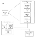
図1は、バーチャルリアリティ(VR : virtual reality)コンソール110が動作するVRシステム環境100のブロック図である。図1に示すシステム環境100は、それぞれVRコンソール110に結合される、VRヘッドセット105、撮像デバイス135、およびVR入力インタフェース140を含む。図1は、1つのVRヘッドセット105、1つの撮像デバイス135、および1つのVR入力インタフェース140を含む例示的なシステム100を示すが、他の実施形態では、システム100に任意の数のこれらの構成要素が含まれ得る。例えば、それぞれが関連するVR入力インタフェース140を有し、1つ以上の撮像デバイス135によって監視される複数のVRヘッドセット105が存在し、各VRヘッドセット105、VR入力インタフェース140、および撮像デバイス135は、VRコンソール110と通信する。代替的な構成では、異なる構成要素およびさらなる構成要素の両方または一方がシステム環境100に含まれ得る。さらに、いくつかの実施形態では、VRシステム100は、ARシステム環境などの他のシステム環境を含むように修正され得る。
Overview of the system FIG. 1 is a block diagram of a
VRヘッドセット105は、ユーザにメディアを提示するヘッドマウントディスプレイである。VRヘッドセットによって提示されるメディアの例としては、1つ以上の画像、映像、音声またはそれらの何らかの組合せが含まれる。いくつかの実施形態では、音声は、VRヘッドセット105、VRコンソール110、またはその両方からの音声情報を受信して、音声情報に基づいて音声データを提示する外部デバイス(例えば、スピーカおよびヘッドフォンの両方または一方)を介して提供される。VRヘッドセット105の実施形態は、図2Aおよび図2Bと併せて以下にさらに説明する。VRヘッドセット105は、互いに対して堅固にまたは非堅固に結合される1つ以上の剛体を含み得る。剛体を堅固に結合することにより、結合された剛体は単一の剛性体として機能する。これに対して、剛体を非堅固に結合することにより、剛体は互いに対して可動となる。いくつかの実施形態では、VRヘッドセット105は、ARヘッドセットとしても機能し得る。これらの実施形態では、VRヘッドセット105は、コンピュータ生成の要素(例えば、画像、映像、音声など)で、物理的実世界環境の視界を増強させる。
The VR headset 105 is a head-mounted display that presents media to the user. Examples of media presented by a VR headset include one or more images, video, audio or any combination thereof. In some embodiments, the audio receives audio information from the VR headset 105, the
VRヘッドセット105は、像面湾曲補正(FC)ディスプレイ115、1つ以上のロケータ(locator)120、1つ以上の位置センサ125、および慣性計測ユニット(IMU : inertial measurement unit)130を含む。
The VR headset 105 includes an image curvature correction (FC)
FCディスプレイ115は、VRコンソール110から受信したデータに従ってユーザに画像を表示する。いくつかの実施形態では、FCディスプレイ115は、表示ブロックと光学ブロックとを含む。表示ブロックは電子ディスプレイ(例えば、OLED)を含み、光学ブロックは、表示ブロックからユーザの眼に画像を送る1つ以上の光学要素を含む。いくつかの実施形態では、表示ブロックのいくつかまたはすべての機能は光学ブロックの一部であり、またはその逆も同様である。図2B〜図7に関して以下に詳しく説明するように、FCディスプレイ115のブロックは像面湾曲を軽減するように構成されている。例えば、FCディスプレイ115は、電子ディスプレイに結合されたファイバテーパ(fiber taper)を含み、その形状は、ファイバテーパから出力された画像光が像面湾曲に対して補正されるようになっている。別の実施形態では、FCディスプレイ115は、ディフューザを有するプロジェクタであり、ディフューザは、出力された光が像面湾曲に対して補正されるような形状(例えば、湾曲形状)を有している。FCディスプレイ115は、異なる構成によって瞳の泳ぎのための補正を行い得る。可能なFCディスプレイの詳細な構成については、図3〜図7に関して以下に説明する。
The
ロケータ120は、互いに対して、およびVRヘッドセット105上の特定の基準点に対して、VRヘッドセット105上の特定の位置に配置された物体である。ロケータ120は、発光ダイオード(LED)、コーナーキューブリフレクタ(corner cube reflector)、反射マーカー、VRヘッドセット105が動作する環境に対してコントラストをもたらすタイプの光源、またはそれらの何らかの組合せであり得る。ロケータ120が能動的(すなわち、LEDまたは他のタイプの発光デバイス)である実施形態では、ロケータ120は、可視光域内(約380nmから750nm)、赤外(IR)域内(約750nmから1mm)、紫外域内(10nmから380nm)、電磁スペクトルの他の部分、またはそれらの何らかの組合せの光を放射し得る。
The
いくつかの実施形態では、ロケータ120は、VRヘッドセット105の外面の下方に配置され、外面は、ロケータ120が放射もしくは反射した光の波長に対して透過性を有するか(transparent)、またはロケータ120が放射もしくは反射した光の波長を実質的に減衰しないのに十分な薄さである。さらに、いくつかの実施形態では、VRヘッドセット105の外面または他の部分は、光の波長の可視光域内で不透過性を有する(opaque)。したがって、ロケータ120は、IR域内では透過性を有するが可視光域内では不透過性を有する外面下方にIR光域内の光を放射し得る。
In some embodiments, the
IMU130は、1つ以上の位置センサ125から受信した測定信号に基づいて高速較正データを生成する電子デバイスである。位置センサ125は、VRヘッドセット105の動きに応答して1つ以上の測定信号を生成する。位置センサ125の例としては、1つ以上の加速度計、1つ以上のジャイロスコープ、1つ以上の磁力計、動きを検出する他の適切なタイプのセンサ、IMU130の誤差補正に使用されるタイプのセンサ、またはそれらの何らかの組合せが含まれる。位置センサ125は、IMU130の外側、IMU130の内側、またはそれらの何らかの組合せに配置され得る。
The
1つ以上の位置センサ125からの1つ以上の測定信号に基づいて、IMU130は、VRヘッドセット105の初期位置に対するVRヘッドセット105の推定位置を示す高速較正データを生成する。例えば、位置センサ125は、並進運動(前方/後方、上方/下方、左方/右方)を測定するための複数の加速度計および回転運動(例えば、ピッチ、ヨー、ロール)を測定するための複数のジャイロスコープを含む。いくつかの実施形態では、IMU130は、測定信号を迅速にサンプリングし、サンプリングしたデータからVRヘッドセット105の推定位置を計算する。例えば、IMU130は、速度ベクトルを推定するために一定期間、加速度計から受信した測定信号を積分し、VRヘッドセット105上の基準点の推定位置を判定するために一定期間、速度ベクトルを積分する。あるいは、IMU130は、サンプリングした測定信号をVRコンソール110に提供し、それにより高速較正データを判定する。基準点は、VRヘッドセット105の位置を示すために使用される点である。基準点は、一般的に空間内の点として画定されるが、実際には、基準点はVRヘッドセット105内の点(例えば、IMU130の中心)として画定される。
Based on one or more measurement signals from one or
IMU130は、VRコンソール110から1つ以上の較正パラメータを受信する。以下にさらに説明するように、1つ以上の較正パラメータは、VRヘッドセット105のトラッキングを維持するために使用される。受信した較正パラメータに基づいて、IMU130は、1つ以上のIMUパラメータ(例えば、サンプルレート)を調整し得る。いくつかの実施形態において、特定の較正パラメータは、IMU130に、基準点の次の較正点に対応するように、基準点の初期位置を更新させる。基準点の次の較正点として基準点の初期位置を更新することは、判定された推定位置に関連する蓄積された誤差の削減に役立つ。ドリフト誤差とも称される蓄積された誤差は、基準点の推定位置を、基準点の実際の位置から経時的に「ドリフト」させる。
The
撮像デバイス135は、VRコンソール110から受信した較正パラメータに従って低速較正データを生成する。低速較正データは、撮像デバイス135によって検出可能なロケータ120の観測位置を示す1つ以上の画像を含む。撮像デバイス135は、1つ以上のカメラ、1つ以上のビデオカメラ、1つ以上のロケータ120を含む画像を取り込み可能な任意の他のデバイス、またはそれらの何らかの組合せを含み得る。さらに、撮像デバイス135は、(例えば、信号対雑音比を増加させるために使用される)1つ以上のフィルタを含み得る。撮像デバイス135は、撮像デバイス135の視野内のロケータ120から放射または反射された光を検出するように構成されている。ロケータ120が受動要素(例えば、再帰反射器)を含む実施形態では、撮像デバイス135は、いくつかのまたはすべてのロケータ120を照らす光源を含み、それにより光を撮像デバイス135内の光源に向けて再帰反射する。低速較正データは、撮像デバイス135からVRコンソール110へ通信され、撮像デバイス135は、VRコンソール110から1つ以上の較正パラメータを受信して、1つ以上の撮像パラメータ(例えば、焦点距離、焦点、フレームレート、ISO、センサ温度、シャッター速度、アパーチャなど)を調整する。
The
VR入力インタフェース140は、ユーザがアクション要求をVRコンソール110に送信することを可能にするデバイスである。アクション要求は、特定のアクションを実施するための要求である。例えば、アクション要求は、アプリケーションの開始または終了を行うこと、またはアプリケーション内の特定のアクションを実施することであり得る。VR入力インタフェース140は、1つ以上の入力デバイスを含み得る。入力デバイスの例としては、キーボード、マウス、ゲームコントローラ、またはアクション要求を受信して受信したアクション要求をVRコンソール110に通信するのに適した任意の他のデバイスが含まれ得る。VR入力インタフェース140によって受信されたアクション要求は、VRコンソール110に通信され、それによりアクション要求に対応するアクションを実施する。いくつかの実施形態において、VR入力インタフェース140は、VRコンソール110から受信された命令に従ってユーザに触覚フィードバックを提供し得る。例えば、触覚フィードバックは、アクション要求を受信したときに提供されるか、あるいはVRコンソール110は、VRコンソール110がアクションを実施するときに、VR入力インタフェース140に触覚フィードバックを生成させる命令をVR入力インタフェース140に通信する。
The VR input interface 140 is a device that allows the user to send an action request to the
VRコンソール110は、VRヘッドセット105に、撮像デバイス135、VRヘッドセット105、およびVR入力インタフェース140のうちの1つ以上から受信した情報に従ってユーザに提示するためのメディアを提供する。図1に示す例では、VRコンソール110は、アプリケーションストア145、トラッキングモジュール150、およびバーチャルリアリティ(VR)エンジン155を含む。VRコンソール110のいくつかの実施形態は、図1に関連して説明するものとは異なるモジュールを有している。同様に、以下にさらに説明する機能は、VRコンソール110の複数の構成要素の間で、本明細書で説明するものとは異なる方法で分散され得る。
The
アプリケーションストア145は、VRコンソール110によって実行される1つ以上のアプリケーションを記憶している。アプリケーションは、プロセッサによって実行されたときにユーザに提示するためのコンテンツを生成する命令群である。アプリケーションによって生成されたコンテンツは、HRヘッドセット105またはVR入力インタフェース140の動きを介してユーザから受信した入力に応答する。アプリケーションの例としては、ゲームアプリケーション、会議アプリケーション、ビデオ再生アプリケーション、または他の適切なアプリケーションが含まれる。
The
トラッキングモジュール150は、1つ以上の較正パラメータを使用してVRシステム100を較正し、VRヘッドセット105の位置の判定の誤差を削減するために1つ以上の較正パラメータを調整し得る。例えば、トラッキングモジュール150は、撮像デバイス135の焦点を調節して、VRヘッドセット105上の観測されたロケータのより正確な位置を取得する。さらに、トラッキングモジュール150によって実施される較正は、IMU130から受信した情報も考慮に入れる。また、VRヘッドセット105のトラッキングが失われた場合は(例えば、撮像デバイス135がロケータ120の少なくとも閾値数の視線を失う場合)、トラッキングモジュール140は、システム環境100の一部または全部を再較正する。
The
トラッキングモジュール150は、撮像デバイス135からの低速較正情報を使用してVRヘッドセット105の動きをトラッキングする。トラッキングモジュール150は、低速較正情報からの観測されたロケータおよびVRヘッドセット105のモデルを使用して、VRヘッドセット105の基準点の位置を判定する。トラッキングモジュール150はまた、高速較正情報からの位置情報を使用してVRヘッドセット105の基準点の位置を判定する。さらに、いくつかの実施形態では、トラッキングモジュール150は、ヘッドセット105の将来の位置を予測するために、高速較正情報、低速較正情報、またはそれらの何らかの組合せの一部を使用し得る。トラッキングモジュール150は、VRヘッドセット105の推定または予測された将来の位置をVRエンジン155に提供する。
The
VRエンジン155は、システム環境100内でアプリケーションを実行し、トラッキングモジュール150から、VRヘッドセット105の位置情報、加速度情報、速度情報、予測された将来の位置、またはそれらの何らかの組合せを受信する。受信した情報に基づいて、VRエンジン155は、ユーザへの提示用にVRヘッドセット105に提供するコンテンツを判定する。例えば、受信した情報が、ユーザが左を見たことを示す場合、VRエンジン155は、仮想環境でユーザの動きをミラーリングする、VRヘッドセット105のためのコンテンツを生成する。また、VRエンジン155は、VR入力インタフェース140から受信したアクション要求に応答してVRコンソール110上で実行するアプリケーション内でアクションを実施し、アクションが実施されたというフィードバックをユーザに提供する。提供されるフィードバックは、VRヘッドセット105を介した視覚的もしくは聴覚的フィードバック、またはVR入力インタフェース140を介した触覚フィードバックであり得る。
The VR engine 155 runs an application within the
図2Aは、一実施形態による、バーチャルリアリティ(VR)ヘッドセット200の図である。VRヘッドセット200は、VRヘッドセット105の一実施形態であり、前方剛体205およびバンド210を含む。前方剛体205は、像面湾曲補正ディスプレイ115の1つ以上の電子表示要素(図2Aには図示せず)、IMU130、1つ以上の位置センサ125、およびロケータ120を含む。図2Aに示す実施形態では、位置センサ125は、IMU130内に配置され、IMU130も位置センサ125もユーザには見えない。
FIG. 2A is a diagram of a virtual reality (VR)
1つ以上のロケータ120は、互いに対しておよび基準点215に対して前方剛体205上の固定位置に配置されている。図2Aの例では、基準点215は、IMU130の中心に配置されている。1つ以上のロケータ120はそれぞれ、撮像デバイス135によって検出可能な光を放射する。1つ以上のロケータ120、または1つ以上のロケータ120の一部は、図2Aの例の前方剛体205の前方側220A、上面側220B、底面側220C、右側220D、および左側220Eに配置されている。VRヘッドセット200は、ARヘッドセットとして機能するように修正され得ることに留意されたい。
One or
図2Bは、図2Aに示すVRヘッドセット200の実施形態の前方剛体205の断面図225である。図2Bに示すように、前方剛体205は、変更された画像光を射出瞳250に提供するFCディスプレイ115を含む。FCディスプレイ115は、表示ブロック228および光学ブロック218を含む。射出瞳250は、ユーザの眼245が配置された前方剛体205の位置である。説明の目的のために、図2Bは、片方の眼245に関する断面図225を示しているが、FCディスプレイ115とは別個のもう1つのFCディスプレイが、ユーザのもう片方の眼に、変更された画像光を提供する。
FIG. 2B is a
表示ブロック228は、画像光を生成する。いくつかの実施形態では、光が、像面湾曲および他の収差の両方または一方に対して補正される。FCディスプレイ115は、VRコンソール110から受信したデータに従ってユーザに画像を表示する。様々な実施形態において、FCディスプレイ115は、単一の電子ディスプレイまたは複数の電子ディスプレイ(例えば、ユーザのそれぞれの眼に対して1つのディスプレイ)を含み得る。電子ディスプレイの例としては、液晶ディスプレイ(LCD)、有機発光ダイオード(OLED)ディスプレイ、アクティブマトリクス有機発光ダイオードディスプレイ(AMOLED)、透明有機発光ダイオードディスプレイ(TOLED)、他の何らかのディスプレイ、プロジェクタ、またはそれらの何らかの組合せが含まれる。FCディスプレイ115はまた、瞳の泳ぎを最小化するために表示ブロックの光学要素も含み得る。表示ブロックの光学要素は、アパーチャ、フレネルレンズ、凸レンズ、凹レンズ、フィルタ、偏光子、ディフューザ、ファイバテーパ、または電子ディスプレイから放射された画像光に影響を与える他の任意の適切な光学要素であり得る。いくつかの実施形態では、1つ以上の表示ブロックの光学要素は、反射防止コーティングなどの1つ以上のコーティングを有し得る。
The display block 228 generates image light. In some embodiments, the light is corrected for curvature of field and / or other aberrations. The
光学ブロック218は、表示ブロック228から受光した光を拡大し、画像光に関連する光学収差を補正し、補正された画像光が、VRヘッドセット105のユーザに提示される。光学要素は、アパーチャ、フレネルレンズ、凸レンズ、凹レンズ、フィルタ、または表示ブロック228から放射された画像光に影響を与える他の任意の適切な光学要素であり得る。さらに、光学ブロック218は、異なる光学要素の組合せを含み得る。いくつかの実施形態において、光学ブロック218内の1つ以上の光学要素は、反射防止コーティングなどの1つ以上のコーティングを有し得る。光学ブロック218による画像光の拡大により、表示ブロック228の要素を物理的に小型化し、軽量化し、より大きなディスプレイよりも消費電力を削減することが可能となる。また、拡大により、表示メディアの視野が広がり得る。例えば、表示メディアの視野は、ユーザの視野のほぼすべて(例えば、斜め方向110度)、また、いくつかの場合にはすべてを使用して、表示メディアが提示されるというものである。いくつかの実施形態では、光学ブロック218は、その有効焦点距離が、表示ブロック228に対する間隔よりも大きくなるように構成されており、それにより表示ブロック228によって投影された画像光を拡大する。また、いくつかの実施形態では、拡大量は、光学要素を追加または削除することによって調整され得る。 The optical block 218 magnifies the light received from the display block 228, corrects the optical aberration associated with the image light, and presents the corrected image light to the user of the VR headset 105. The optical element can be an aperture, a Fresnel lens, a convex lens, a concave lens, a filter, or any other suitable optical element that affects the image light emitted from the display block 228. Further, the optical block 218 may include a combination of different optical elements. In some embodiments, the one or more optical elements within the optical block 218 may have one or more coatings, such as an antireflection coating. The enlargement of the image light by the optical block 218 makes it possible to physically reduce the size and weight of the elements of the display block 228 and reduce the power consumption as compared with the larger display. In addition, the field of view of the display medium can be expanded by enlarging. For example, the field of view of the display medium is such that the display medium is presented using almost all of the user's field of view (eg, 110 degrees in the oblique direction) and, in some cases, all. In some embodiments, the optical block 218 is configured such that its effective focal length is greater than the spacing with respect to the display block 228, thereby enlarging the image light projected by the display block 228. Also, in some embodiments, the amount of magnification can be adjusted by adding or removing optical elements.
表示ブロック228および光学ブロック218は、FCディスプレイ115内で異なる構成を有し得る。異なる構成については、図3A〜図7Bに関して以下に説明する。
図3Aは、一実施形態による、FCディスプレイ315の断面図300である。いくつかの実施形態では、FCディスプレイ315は、VRヘッドセット105のFCディスプレイ115の一部である。他の実施形態では、FCディスプレイ315は、例えば、ARディスプレイ、HMD、VRディスプレイ、デジタル顕微鏡などの他の電子ディスプレイの一部である。FCディスプレイ315は、表示ブロック328および光学ブロック318を含む。FCディスプレイ315は、例えば、光学系(例えば、光学ブロック318)の焦点面と一致する形状に画像光を放射することにより、像面湾曲に対する補正を行う(およびそれにより瞳の泳ぎを軽減する)。射出瞳350は、ユーザの眼345が配置される位置である。説明の目的のために、図3Aは、片方の眼345に関するFCディスプレイ315の断面図を示しているが、FCディスプレイ315とは別個のもう1つのFCディスプレイが、ユーザのもう片方の眼に、変更された画像光を提供する。FCディスプレイ315のいくつかの実施形態は、本明細書に記載するものとは異なる構成要素を有している。同様に、いくつかの場合、機能は、その構成要素間で、本明細書で説明するものとは異なる方法で分散されることができる。表示ブロック328は、電子表示パネル330およびファイバテーパ(fiber taper)340を含む。電子表示パネル330は、電子信号からの視覚的情報を提示する。電子ディスプレイパネル330の例としては、液晶ディスプレイ(LCD)、有機発光ダイオード(OLED)ディスプレイ、アクティブマトリクス有機発光ダイオードディスプレイ(AMOLED)、何らかのタイプのフレキシブルディスプレイ、またはそれらの何らかの組合せが含まれる。
The display block 228 and the optical block 218 may have different configurations within the
FIG. 3A is a
ファイバテーパ340は、テーパ形状の光ファイバプレートである。光ファイバプレートは光ファイバの束でできており、その入力面からその出力面へ光を直接的に示す。テーパ形状の光ファイバプレートは典型的に、光ファイバフェースプレート(fiber optic faceplate)上に熱処理を用いて作成され、出力面に対する入力面の大きさの比率を変更する。ファイバテーパは、電子表示パネル330の拡大を可能にするために使用され、ファイバテーパ340の表示面342は、光ファイバフェースプレートと同様の湾曲した表示面になるように研磨されることができる。
The
ファイバテーパ340の取付面344は、電子表示パネル330の表面に形成され、かつ取り付けられている。ファイバテーパ340は、取付面344を介して表示パネル330から光を受光し、受光した光を、出力された画像光が像面湾曲に対して補正されるような形状の表示面342を介して出力する複数の光ファイバを含む。本実施形態では、表示面342は、球面凹状(例えば、球形の一部)に形成される。しかし、他の実施形態では、表示面342は、球面凸状、回転対称球面、非球面、自由形状、または像面湾曲および他の光学収差を軽減する何らかの他の形状であり得る。いくつかの実施形態では、表示面342の形状は、例えば場依存収差などの他の形態の光学収差に対する補正をさらに行うように構成され得る。
The mounting surface 344 of the
本実施形態では、電子表示パネル330は平坦な表面を有しており、したがって、ファイバテーパ340の取付面344も平坦である。あるいは、図示しないが、電子表示パネル330は円筒状に湾曲しているか、または何らかの他の形状を有し得る。取付面344は、ファイバテーパ340の取付面344が電子表示パネル330の表面に固定されるように、電子表示パネル330の表面と一致するように形成されている。例えば、電子表示パネルの表面が平坦である場合、取付面344は平坦であり、電子表示パネルの表面が円筒状に凸状である場合は、取付面344は円筒状に凹状である。電子表示パネル330および取付面344は、ディスプレイからの光がファイバテーパ340に入る前に拡散して近傍画素と混合する(クロストーク(optical cross talk))ことを防止するために、取付面344と電子表示パネルのカバーガラスとの間にエアギャップまたは分離がないように結合され得る。一実施形態では、電子表示パネル330のカバーガラスは光ファイバフェースプレートであり、これは、表示パネル330から出た光の、ファイバテーパ340に入る前の光学的なクロストークを防止することを支援するためにファイバテーパ340と組み合わせて使用され得る。別の実施形態では、電子表示パネル330のカバーガラスは、表示パネル330から出た光の、ファイバテーパ340に入る前の光学的なクロストークを削減するための、画素ピッチよりも小さい厚みの一片の封止フィルムである。また、ファイバテーパ340のファイバの直径は、近傍画素からの光との混合を防止するために、電子表示パネル330の画素ピッチと同じか、またはそれよりも小さいサイズである。像面湾曲に対する補正を行うためにファイバテーパを使用する本実施形態の1つの利点は、この技術によって、平坦なパネルのディスプレイを使用できることである。平坦なパネルのディスプレイは、一般的に、湾曲したディスプレイよりも安価であり作成が容易である。
In this embodiment, the
別の実施形態では、図3Aには図示しないが、ファイバテーパ340は光ファイバフェースプレートであることができ、電子表示パネル330は湾曲したディスプレイであることができる。別の実施形態では、電子表示パネル330のカバーガラスは、ファイバテーパ340に代わる光ファイバフェースプレートであり得る。この光ファイバフェースプレートは、拡大または画像サイズの変更を提供する必要はないが、結像面の形状を変更し得る。この形状は、光学ブロック318から生成されたネットフィールド湾曲によって判定され得る。例えば、光学ブロック318が正屈折レンズ要素で構成されている場合、これらの要素からの像面湾曲は凹状結像面を生成し、光ファイバフェースプレートの表面は、光学ブロック318によって生成された像面湾曲を補うように凹状の結像面を作成する形状とすることができる。異なる例では、光学ブロック318が反射正レンズ要素で構成されている場合、これらの要素からの像面湾曲は凸状結像面を生成し、光ファイバフェースプレートの表面はそれに応じて補うような形状とすることができる。光ファイバフェースプレートの開口数は、光が空気と光ファイバフェースプレートとの間の境界面で屈折して光学ブロック318を通過した後にアイボックスが満たされるような大きさである。
In another embodiment, although not shown in FIG. 3A, the
光学ブロック318は、表示ブロックから受光した光を拡大し、画像光に関する光学収差を補正する。光学ブロック318は、光学ブロック218と同様の機能を有している。光学ブロック318は、レンズホルダ320によって結合されたレンズ321およびレンズ322で構成されている。光学ブロック318内のレンズは、反射防止コーティングなどの1つ以上のコーティングを有し得る。
The
図3Bは、一実施形態による、図3Aに示すFCディスプレイ315を含むディスプレイアセンブリ340の斜視図である。本実施形態では、FCディスプレイアセンブリ340は、各ディスプレイがユーザのそれぞれの眼に対応する、2つのFCディスプレイ要素315で構成されている。FCディスプレイアセンブリ340は、2つの表示ブロック328aおよび328bと、2つの対応する光学ブロック318aおよび318bとを含み、それらは、図3Aに示す表示ブロック328および光学ブロック318と同じである。
FIG. 3B is a perspective view of the
図4は、一実施形態による、投影型表示ブロック428を含むFCディスプレイ415の実施形態の断面図400である。いくつかの実施形態では、FCディスプレイ415は、VRヘッドセット105のFCディスプレイ115の一部である。他の実施形態では、これは、例えば、ARディスプレイ、HMD、VRディスプレイ、デジタル顕微鏡など、何らかの他の電子ディスプレイの一部である。FCディスプレイ415は、表示ブロック428および光学ブロック418を含む。FCディスプレイ415は、表示ブロック428に、光学系(例えば、光学ブロック418)の湾曲した焦点面と一致する湾曲面に画像光を放射させることによって、像面湾曲に対する補正を行う。射出瞳450は、ユーザの眼445が配置される位置である。説明の目的のために、図4は、片方の眼445に関するFCディスプレイ415の断面図を示しているが、FCディスプレイ415とは別個のもう1つのFCディスプレイが、ユーザのもう片方の眼に、変更された画像光を提供する。FCディスプレイ415のいくつかの実施形態は、本明細書に記載するものとは異なる構成要素を有している。同様に、いくつかの場合、機能は、その構成要素間で、本明細書で説明するものとは異なる方法で分散されることができる。
FIG. 4 is a
表示ブロック428は、プロジェクタ430およびディフューザ440を含む。プロジェクタ430は、レーザプロジェクタ、ピコプロジェクタ、またはデジタルミラーデバイス(DMD)を用いたものなど他のタイプのプロジェクタであり得る。ディフューザ440は、プロジェクタ430から投影された光を放散する。ディフューザ440の形状は、出力された画像光が、光学ブロック418の焦点面に対応する湾曲した画像面に沿っており、それに応じて像面湾曲に対する補正が行われるようになっている。本実施形態では、ディフューザ440は、球面凹状(例えば、球形の一部)に形成されている。しかし、他の実施形態では、ディフューザ440は、球面凸状、回転対称球面、自由形状、または像面湾曲を軽減する何らかの他の形状であり得る。いくつかの実施形態では、ディフューザ440の形状は、他の形態の光学収差に対する補正をさらに行うように構成され得る。ディフューザ440の粒径(grain size)は、例えばVRヘッドセット105内で使用された場合など、視聴者が見たときに好ましくない画面の乱れ(スクリーンアーティファクト)を有することを避けるために、画素ピッチよりも桁違いに小さい粒径を有し得る。本実施形態では、プロジェクタ430は、ユーザの眼445に対してディフューザ440の背面側に配置される。代替的な実施形態では、図示しないが、プロジェクタ430は、ユーザの眼445に対してディフューザ440の正面側に配置される可能性があり、ディフューザ440は反射面である可能性がある。
The display block 428 includes a
光学ブロック418は、図3Aの光学ブロック318と同様である。光学ブロック418は、レンズ421およびレンズ422の2つのレンズを収容している。これらのレンズは、図示しないが、レンズホルダで結合される可能性がある。光学ブロックは、表示ブロックから受光した光を拡大し、画像光に関する光学収差を補正する。
The
図5Aは、一実施形態による、湾曲した反射偏光子を含むFCディスプレイ505の実施形態の断面図500である。いくつかの実施形態では、FCディスプレイ505は、VRヘッドセット105のFCディスプレイ115の一部である。他の実施形態では、これは、例えば、ARディスプレイ、HMD、VRディスプレイ、デジタル顕微鏡など、何らかの他の電子ディスプレイの一部である。FCディスプレイ505は、表示ブロック510および光学ブロック515を含む。射出瞳518は、ユーザの眼520が配置される位置である。説明の目的のために、図5Aは、片方の眼520に関するFCディスプレイ505の断面図を示しているが、FCディスプレイ505とは別個のもう1つのFCディスプレイが、ユーザのもう片方の眼に、変更された画像光を提供する。FCディスプレイ505のいくつかの実施形態は、本明細書に記載するものとは異なる構成要素を有している。同様に、いくつかの場合、機能は、その構成要素間で、本明細書で説明するものとは異なる方法で分散されることができる。
FIG. 5A is a
表示ブロック510は、像面湾曲に対する補正を行った光を放射する。表示ブロック510は、電子表示パネル、反射偏光子、1つ以上の1/4波長板、1つ以上の鏡面反射器、1つ以上の直線偏光子、またはそれらの何らかの組合せを含み得る。いくつかの実施形態では、電子表示パネルは部分的に反射し、例えばブラックマトリクスなどの画素領域の外側の領域内、または、ディスプレイの光を放射しない領域内で反射する。他の実施形態では、電子表示パネルは、透明電子表示パネルであることができる。透明電子表示パネルは、例えば、透明有機発光ダイオードディスプレイ(TOLED)、他の何らかの透明の電子ディスプレイ、またはそれらの何らかの組合せであり得る。
The
反射偏光子は、像面湾曲に対する補正を行い、かつ光を偏光するような形状の湾曲した光学要素である。反射偏光子は、x方向に直線偏光された光を反射し、y方向に直線偏光された光を透過させるよう構成され得る(またはその逆もあり得る)。反射偏光子は、負のペッツバル湾曲を提供するために球面凹状(例えば、球形の一部)に形成され得る。しかし、他の実施形態では、反射偏光子は、球面凸状、回転対称非球面、自由形状、または像面湾曲を軽減する何らかの他の形状であり得る。いくつかの実施形態では、反射偏光子の形状は、他の形態の光学収差に対する補正をさらに行うように構成され得る。反射偏光子要素の機能については、図5B〜図5Dに関して以下に詳細に説明する。 The reflection polarizer is a curved optical element having a shape that corrects curvature of field and polarizes light. The reflection polarizer may be configured to reflect light linearly polarized in the x direction and transmit light linearly polarized in the y direction (or vice versa). Reflective polarizers can be formed in a spherical concave shape (eg, part of a sphere) to provide a negative Petzval curve. However, in other embodiments, the reflective polarizer can be spherically convex, rotationally symmetric aspherical, free-form, or any other shape that reduces curvature of field. In some embodiments, the shape of the reflected polarizer may be configured to further correct for other forms of optical aberration. The function of the reflective polarizer element will be described in detail below with reference to FIGS. 5B-5D.
表示ブロック510には、1つ以上の1/4波長板要素が含まれる。1/4波長板は偏光軸を含む。偏光軸は、y方向(垂直方向の直線偏光された光の方向)に対して45度(または90度)偏移されている。同様に、1/4波長板は、円偏光された光を直線偏光された光に変換する。直線偏光された入射光に対する1/4波長板軸の向きは、放射された、円偏光された光の巻き方(handedness)(時計回りまたは反時計回り)を制御する。1/4波長板要素の機能については、図5B〜図5Dに関して以下に詳細に説明する。
The
光学ブロック515は、図3Aの光学ブロック318と同様である。光学ブロック515は、レンズ521およびレンズ522の2つのレンズを収容している。これらのレンズは、図示しないが、レンズホルダで結合される可能性がある。光学ブロックは、表示ブロック510から受光した光を拡大し、画像光に関する光学収差を補正する。光学ブロック内のレンズ要素の数およびレンズの設計(形状、屈折/反射、材料、屈折/回析)は、様々とすることができる。
The
図5Bは、一実施形態による、図5Aの表示ブロック510の断面図525である。電子表示パネル526は、円偏光子を含まないOLEDディスプレイ(例えば、直線偏光子および1/4波長板はディスプレイの画素を覆って配置される)であり得る。いくつかの場合、OLEDディスプレイは、ディスプレイ表面からの環境照明の削減およびディスプレイのコントラストの増大を支援するために円偏光子を収容している。しかし、いくつかの場合、OLEDディスプレイがHMD内で使用される場合は、円偏光子は含まれなくともよく、これは、HMDの場合は環境照明がすでにユーザから遮蔽されているためである。電子表示パネル526は、複数の画素群528を含んでいる。各画素群528は、画素530、ブラックマトリクス532、直線偏光子534、鏡面反射器536、および1/4波長板538を含む。画素530は、基板539上に形成されている。ブラックマトリクス532は、画素530を、他の画素群528内の隣接する画素530から分離する。代替的な実施形態では、画素群は、異なるまたはさらなる要素(例えば、複数画素530)を含み得る。
FIG. 5B is a
直線偏光子534は、画素530を覆って配置されている。直線偏光子534は、画素530から放射された光を直線偏光する。偏光子は、直線偏光された光が第1の方向を指向する方向に向けられている。直線偏光子534は、例えば、吸収型偏光子、薄膜偏光子、または光を直線偏光する何らかの他のタイプの偏光子であり得る。
The
鏡面反射器536は、入射光を反射する。鏡面反射器536は、画素530によって放射された波長で光を反射する材料(例えば、アルミニウム、銀)である。鏡面反射器536は、電子表示パネル526のブラックマトリクス532を覆って配置されている。
The
湾曲した反射偏光子540は、図5Aのものと同様であり、電子表示パネル526から放射された光を受光するように配置されている。同様に、1/4波長板538は、図5Aに示すものと同様である。
The curved
所定の画素群528に対して、画素530から放射された光541は、直線偏光子534によって第1の方向に直線偏光される。この直線偏光された光542は、湾曲した反射偏光子540上に入射し、電子表示パネル526に向かって反射し戻される。これは、第1の方向が反射偏光子540の伝達軸に直交しているためである。反射された光543の一部は、1/4波長板538上に入射する。光544は、1/4波長板538を通過し、特定の巻き方(例えば、時計回り)の円偏光された光として出射する。円偏光された光は、鏡面反射器536で反射して、反対の巻き方(例えば、反時計回り)の円偏光された光545になる。反射された光は、1/4波長板538を通過し、直線偏光された光546として1/4波長板538から出射する。光546は、反射偏光子540の伝達軸と整合するように、第1の方向に直交する偏光を有する。光546は、反射偏光子540によって伝達される。図5Cは、一実施形態による、二次1/4波長板551を含む表示ブロック510の断面図550である。表示ブロック510は、電子表示パネル552と湾曲した反射偏光子540との間の二次1/4波長板551を含む。湾曲した反射偏光子540は、図5Aのものと同様である。平坦であるように図示されているが、二次1/4波長板551は、湾曲していることができる。電子表示パネル552は、複数の画素群554を含む。画素群554は、画素556、ブラックマトリクス558、直線偏光子560、1/4波長板562、および鏡面反射器563を含む。画素556は、基板564上に形成されている。ブラックマトリクス558は、画素556を、他の画素群554内の隣接する画素556から分離する。代替的な実施形態では、画素群は、異なるまたはさらなる要素(例えば、複数画素556)を含み得る。
The light 541 emitted from the
直線偏光子560および1/4波長板562は、画素556を覆って配置される円偏光子をともに形成し、鏡面反射器563は、ブラックマトリクス558を覆って配置される。電子表示パネル552の一部として図示されているが、円偏光子および鏡面反射器563は、電子表示パネル552から分離され得る。鏡面反射器563は、図5Cでは分離した層として図示されているが、ブラックマトリクス558は、鏡面反射器であり、同じ層であり得る。
The
所定の画素群554に対して、画素556から放射された光565は、直線偏光子560によって第1の方向に直線偏光され、1/4波長板562は、直線偏光された光566を円偏光された光567に変換する。円偏光された光567は、二次1/4波長板551を通過し、第1の方向に直線偏光された光568になる。光568は、第1の方向が反射偏光子の伝達軸に直交しているため、反射偏光子540によって反射される。二次1/4波長板551は、直線偏光された光569を、円偏光された光570に変換する。円偏光された光570は、特定の巻き方(例えば、時計回りまたは反時計回り)を有する。円偏光された光570の一部571は、鏡面反射器556によって反射される。反射された光571は円偏光されるが、巻き方は、570のそれと反対である。反射された光は、二次1/4波長板551を通過し、直線偏光された光572として二次1/4波長板551から出射する。光572は、反射偏光子540の伝達軸と整合するように、第1の方向に直交する偏光を有する。光572は、反射偏光子540によって伝達される。
The light 565 emitted from the
図5Dは、一実施形態による、透明電子表示パネル576を含む図5Aの表示ブロック510の断面図575である。本実施形態では、電子表示パネル576は、湾曲した反射偏光子540と1/4波長板577との間に配置された透明のディスプレイである。1/4波長板577は、鏡面反射器578を覆って配置されている。湾曲した反射偏光子540は、図5Aのものと同様である。
FIG. 5D is a
電子表示パネル576は、複数の画素群580を含む。画素群は、画素581および直線偏光子582を含む。直線偏光子582は、画素581を覆って配置されているが、画素581の間の領域は覆っていない。画素581は、基板585上に形成されている。基板585、画素580、および直線偏光子582は、実質的に透明である。
The
所定の画素群580に対して、画素581から放射された光591は、直線偏光子582によって第1の方向に直線偏光される。この直線偏光された光592は、反射偏光子540上に入射し、光593として反射される。これは、第1の方向が反射偏光子540の伝達軸に直交しているためである。光593は、透明の基板585を通って伝播し、1/4波長板577上に入射する。光594は、1/4波長板577を通過し、特定の巻き方(例えば、時計回り)の円偏光された光として出射する。円偏光された光は、鏡面反射器578で反射して、反対の巻き方(例えば、反時計回り)の円偏光された光595になる。反射された光は、1/4波長板577を通過し、直線偏光された光596として1/4波長板577から出射する。光596は、反射偏光子540の伝達軸と整合するように、第1の方向に直交する偏光を有する。光596は、基板585を通って伝播し、反射偏光子540によって伝達される。
The light 591 emitted from the
図5A〜図5Dの実施形態の像面湾曲に対する補正のいくつかの利点は、以下に図6に示す実施形態と比較して、特に画素のフィルファクタが低い場合に、より多い光のスループットを有していることを含む。これは、光が表示パネルの複数の画素の間の領域で反射して、部分反射鏡などの構成要素を多数回通過する必要が無いためである。 Some advantages of the correction for curvature of field of the embodiments of FIGS. 5A-5D are higher light throughput, especially when the pixel fill factor is lower, as compared to the embodiments shown below. Including having. This is because the light is reflected in the region between the plurality of pixels of the display panel and does not need to pass through a component such as a partial reflector many times.
図6は、一実施形態による、パンケーキ状レンズアセンブリ620を含むFCディスプレイ615の実施形態の断面図600である。いくつかの実施形態では、FCディスプレイ615は、VRヘッドセット105のFCディスプレイ115の一部である。他の実施形態では、これは、例えば、ARディスプレイ、HMD、VRディスプレイ、デジタル顕微鏡など、何らかの他の電子ディスプレイの一部である。FCディスプレイ615は、電子表示パネル630、偏光子632、およびパンケーキ状レンズアセンブリ620で構成されている。射出瞳650は、ユーザの眼645が配置される位置である。説明の目的のために、図6は、片方の眼645に関するFCディスプレイ615の断面図600を示しているが、FCディスプレイ615とは別個のもう1つのFCディスプレイが、ユーザのもう片方の眼に、変更された画像光を提供する。FCディスプレイ615のいくつかの実施形態は、本明細書に記載するものとは異なる構成要素を有している。同様に、いくつかの場合、機能は、その構成要素間で、本明細書で説明するものとは異なる方法で分散されることができる。
FIG. 6 is a
電子表示パネル630は、図3Aの電子表示パネル330と同様である。図6では、電子表示パネル630とは別個として図示されているが、直線偏光子632は、電子表示パネル630の一部であり得る。電子表示パネル630から放射された光は、直線偏光子632を通ってディスプレイから出射し、それにより、1つの偏光の光をもたらす。
The
パンケーキ状レンズアセンブリ620は、部分反射鏡634および偏光反射鏡638を含む。図6において、部分反射鏡634は、電子表示パネル630の近傍に配置され、偏光反射鏡638は、ユーザの眼645の近傍に配置される。しかし、いくつかの実施形態では、部分反射鏡634は、ユーザの眼645の近傍に配置され、偏光反射鏡638は、電子表示パネル630の近傍に配置され得る。
The
部分反射鏡634および偏光反射鏡638の1つ以上の表面は、像面湾曲に対する補正を行うような形状にされている。部分反射鏡634の1つ以上の表面は、球面凹状(例えば、球形の一部)、球面凸状、回転対称非球面、自由形状、または像面湾曲を軽減する何らかの他の形状に形成され得る。いくつかの実施形態では、部分反射鏡634および偏光反射鏡638の1つ以上の表面の形状は、他の形態の光学収差に対する補正をさらに行うように構成され得る。いくつかの実施形態では、パンケーキ状レンズアセンブリ620内の1つ以上の光学要素は、ゴースト像を削減してコントラストを増強するために、反射防止コーティングなどの1つ以上のコーティングを有し得る。
One or more surfaces of the
部分反射鏡634は、波長板面(wave plate surface)633および鏡面635を含む。波長板面633は、受光した光の偏光を偏移する1/4波長板である。1/4波長板は、偏光軸を含む。偏光軸は、1/4波長板が、直線偏光された光を円偏光された光に変換するように、直線偏光された入射光に対して45度偏移されている。同様に、1/4波長板は、円偏光された光を直線偏光された光に変換する。鏡面635は、受光した光の一部を反射するように構成された部分反射鏡である。いくつかの実施形態では、鏡面635は、入射光の50%を透過させ、入射光の50%を反射するように構成されている。
The
偏光反射鏡638は、波長板面637および反射偏光子面639を含む。波長板面637は、1/4波長板である。反射偏光子面639は、1つの偏光の光を反射し(偏光遮断)、受光した光の第2の偏光(直交する偏光)の光を透過させるように構成された部分反射鏡である。例えば、反射偏光子面639は、x方向に直線偏光された光を反射し、y方向に直線偏光された光を透過させるように構成され得る。
The polarizing reflector 638 includes a wave plate surface 637 and a reflecting
パンケーキ状レンズアセンブリ620は、像面湾曲を軽減して、それに従って瞳の泳ぎを低減するように機能する。また、パンケーキ状レンズアセンブリ620は、像面湾曲を取り除くように設計された他の光学システムと比べて、フォームファクタが小さく、比較的低重量である。
The pancake-
電子表示パネル630から出射する光は、固有的に偏光されているか、直線偏光子632を通過した後に第1の方向に直線偏光された光になるかのいずれかである。直線偏光された光は、波長板面633上に入射し、円偏光された光になる。円偏光された光の一部は、部分反射鏡634の鏡面635を通過する。この円偏光された光は、波長板面637を通過し、第1の方向に直線偏光される。反射偏光子面639は、第1の方向が反射偏光子面639の偏光軸に直交するため、この直線偏光された光を反射する。反射された光は、波長板面637を通して伝播して戻り、光は円偏光される。円偏光された光は、鏡面635上に入射する。円偏光された光の一部は、鏡面635によって反射され、反対の巻き方の円偏光された光になる。反射された円偏光された光は、波長板面637を通過して、第1の方向に直交する第2の方向に偏光された、直線偏光された光になる。第2の方向は、反射偏光子面639の偏光軸と整合する。反射偏光子面639は、直線偏光された光をユーザの眼645に透過させる。
The light emitted from the
像面湾曲に対する補正を行うためにパンケーキ状レンズアセンブリを使用するこの実施形態のいくつかの利点には、小さいフォームファクタ、低重量、および、この技術で平面ディスプレイを使用する能力、を有することが含まれる。 Some advantages of this embodiment of using a pancake-like lens assembly to make corrections for curvature of field are a small form factor, low weight, and the ability to use a flat display in this technique. Is included.
図7Aは、一実施形態による、3つのレンズを含むFCディスプレイ715の別の実施形態の断面図700である。いくつかの実施形態では、FCディスプレイ715は、VRヘッドセット105のFCディスプレイ115の一部である。他の実施形態では、これは、例えば、ARディスプレイ、HMD、VRディスプレイ、デジタル顕微鏡など、何らかの他の電子ディスプレイの一部である。FCディスプレイ715は、表示ブロック728および光学ブロック718を含む。射出瞳750は、ユーザの眼745が配置される位置である。説明の目的のために、図7Aは、片方の眼745に関するFCディスプレイ715の断面図を示しているが、FCディスプレイ715とは別個のもう1つのFCディスプレイが、ユーザのもう片方の眼に、変更された画像光を提供する。FCディスプレイ715のいくつかの実施形態は、本明細書に記載するものとは異なる構成要素を有している。同様に、いくつかの場合、機能は、その構成要素間で、本明細書で説明するものとは異なる方法で分散されることができる。
FIG. 7A is a
表示ブロック728は、電子表示パネル730で構成されている。電子表示パネル730は、図3Aの電子表示パネル330と同様である。
光学ブロック718は、図3Aの光学ブロック318と同様である。光学ブロック718は、レンズ721、レンズ722、およびレンズ723の3つのレンズを収容している。本実施形態では、レンズ723は、球面凹状(例えば、球形の一部)に形成された複合レンズである。しかし、他の実施形態では、レンズ723は、球面凸状、回転対称球面、自由形状、または像面湾曲を軽減する何らかの他の形状であり得る。いくつかの実施形態では、レンズ723の形状は、他の形態の光学収差に対する補正をさらに行うように構成され得る。これらのレンズは、図示しないが、レンズホルダで結合される可能性がある。光学ブロックは、表示ブロック728から受光した光を拡大し、画像光に関する光学収差を補正する。
The display block 728 is composed of an
The
図7Bは、一実施形態による、2つのレンズを有するFCディスプレイ755の別の実施形態の断面図751である。いくつかの実施形態では、FCディスプレイ755は、VRヘッドセット105のFCディスプレイ115の一部である。他の実施形態では、これは、例えば、ARディスプレイ、HMD、VRディスプレイ、デジタル顕微鏡など、何らかの他の電子ディスプレイの一部である。FCディスプレイ755は、表示ブロック728および光学ブロック758を含む。射出瞳750は、ユーザの眼745が配置される位置である。説明の目的のために、図7Bは、片方の眼745に関するFCディスプレイ755の断面図を示しているが、FCディスプレイ755とは別個のもう1つのFCディスプレイが、ユーザのもう片方の眼に、変更された画像光を提供する。FCディスプレイ755のいくつかの実施形態は、本明細書に記載するものとは異なる構成要素を有している。同様に、いくつかの場合、機能は、その構成要素間で、本明細書で説明するものとは異なる方法で分散されることができる。本実施形態では、光学ブロック758は、2つの異なる種類のプラスチックを用いた全プラスチック設計であり、「逆ケルナー(reversed Kellner)」アイピース設計(eyepiece design)の変形例である。光学ブロック758は、レンズ761およびレンズ762の2つのレンズを含み、レンズ762はダブレットである。この設計は、大きな視野(80度以上の全視野)および適正なアイレリーフ(eye relief)を提供することができる。
FIG. 7B is a
図7Aおよび図7Bに示す実施形態では、像面湾曲に対する補正を行うために少なくとも1つの負要素が使用されている。例えば、図7Aでは、レンズ721とレンズ723の一部とが負要素である。図7Bでは、レンズ762の一部762bが負要素である。レンズは、ガラス、プラスチック、またはガラスとプラスチックとの組合せで設計され作成されることができる。プラスチックは、その軽量さ、および低コストの作成方法の可用性により、材料として好ましいものであり得る。異なる分散パラメータを有する異なる材料を使用することにより、軸上および横方向の色収差に対する補正が支援される。個々のレンズ面は、球面、非球面、または自由形状の表面とすることができる。
In the embodiments shown in FIGS. 7A and 7B, at least one negative element is used to make corrections for curvature of field. For example, in FIG. 7A, the
追加構成情報
本開示の実施形態の前述の説明は、例示の目的のために提示されており、網羅的であること、または、開示された正確な形態に本開示を限定することを意図するものではない。関連技術の当業者は、上記の開示に照らして多くの修正および変形が可能であることを理解することができる。
Additional Configuration Information The aforementioned description of embodiments of this disclosure is presented for illustrative purposes and is intended to be exhaustive or to limit this disclosure to the exact form disclosed. is not it. One of ordinary skill in the art of the art can appreciate that many modifications and modifications are possible in light of the above disclosure.
本明細書で使用される言語は、主として読みやすさおよび説明を目的として選択されており、本発明の主題を線引きまたは画定するように選択されていない可能性がある。したがって、本開示の範囲は、この詳細な説明によってではなく、むしろ、これに基づいて本願について発行される任意の特許請求の範囲によって限定されるものである。したがって、開示された実施形態は、特許権の範囲を例示することを意図しているが、以下の特許請求の範囲に規定される開示の範囲を限定するものではない。 The language used herein has been selected primarily for readability and description purposes and may not have been selected to delineate or delineate the subject matter of the invention. Therefore, the scope of the present disclosure is not by this detailed description, but rather by the scope of any claims issued for the present application on the basis of this. Therefore, the disclosed embodiments are intended to illustrate the scope of patent rights, but do not limit the scope of disclosure specified in the following claims.
Claims (7)
前記ヘッドマウントディスプレイのユーザの眼に出力された画像内の像面湾曲に対する補正を行うように構成された像面湾曲補正(FC)ディスプレイを含み、
前記像面湾曲補正ディスプレイは、表示ブロックと光学ブロックとを含み、前記表示ブロックは、
画像光を出力するように構成された電子表示パネルと、
前記電子表示パネルから前記画像光を受光するように構成された反射偏光子であって、修正された画像光を出力して像面湾曲に対する補正を行うための形状を有する反射偏光子と、を含み、
前記光学ブロックは、前記修正された画像光を前記表示ブロックの前記反射偏光子から受光し、像面湾曲に対する補正を行った画像光を、前記ヘッドマウントディスプレイのユーザの眼の位置に対応する前記ヘッドマウントディスプレイの射出瞳に光学的に向けるように構成され、
前記表示ブロックおよび前記光学ブロックのうちの少なくとも1つが、像面湾曲に対して前記画像光を光学的に補正する、ヘッドマウントディスプレイ。 It is a head-mounted display (HMD)
The head-mounted display includes an image curvature correction (FC) display configured to correct for curvature of field in an image output to the user's eye.
The curvature-field correction display includes a display block and an optical block, and the display block includes a display block and an optical block.
An electronic display panel configured to output image light,
A reflective polarizing element configured to receive the image light from the electronic display panel and having a shape for outputting the corrected image light and correcting for curvature of field. Including
The optical block receives the modified image light from the reflected polarizer of the display block, and corrects the image plane curvature for the image light corresponding to the position of the user's eye of the head-mounted display. It is configured to be optically oriented toward the exit pupil of the head-mounted display.
A head-mounted display in which at least one of the display block and the optical block optically corrects the image light for curvature of field.
前記電子表示パネルの反射面と、
前記反射面に結合された1/4波長板とをさらに含み、
前記反射偏光子は、前記電子表示パネルから放射された1つの偏光の前記画像光を反射し、前記電子表示パネルの前記反射面から反射され、前記電子表示パネルの前記反射面上の前記1/4波長板を通過する別の偏光の前記画像光を透過させるように構成されている、請求項1に記載のヘッドマウントディスプレイ。 The display block is
The reflective surface of the electronic display panel and
Further comprising a quarter-wave plate coupled to the reflective surface,
The reflected polarizer reflects the image light of one polarized light emitted from the electronic display panel, is reflected from the reflective surface of the electronic display panel, and is reflected from the reflective surface of the electronic display panel, and the 1/1 on the reflective surface of the electronic display panel. The head-mounted display according to claim 1, which is configured to transmit the image light of another polarized light passing through a four-wavelength plate.
前記像面湾曲補正ディスプレイは、第1の1/4波長板をさらに含み、
前記反射偏光子は、
前記電子表示パネルから放射され、前記第1の1/4波長板を通過する1つの偏光の前記画像光を反射し、
前記第1の1/4波長板を通過した後に、前記電子表示パネルの前記表面上の前記電子表示パネルの前記反射面から反射した別の偏光の前記画像光を透過させる
ように構成されている、請求項1に記載のヘッドマウントディスプレイ。 The display block further comprises a pre-Symbol the reflecting surface of the electronic display panel on the surface of the electronic display panel,
The curvature correction display further comprises a first quarter wave plate,
The reflected polarizer is
The emitted from the electronic display panel, and reflecting the image light of one polarization you through the first quarter-wave plate,
After over through the first quarter-wave plate is configured to Ru is transmitted through the image light of another polarization reflected from said reflective surface of the electronic display panel on the surface of the electronic display panel The head-mounted display according to claim 1.
前記反射偏光子は、 The reflected polarizer is
前記電子表示パネルから放射され、前記第1の1/4波長板を1度通過し、前記第2の1/4波長板を1度通過する1つの偏光の前記画像光を反射し、 Reflects the one polarized image light emitted from the electronic display panel, passing once through the first quarter wave plate and once passing through the second quarter wave plate.
前記第1の1/4波長板を1度通過し、前記第2の1/4波長板を1度通過した後に、前記電子表示パネルの前記表面上の前記電子表示パネルの前記反射面から反射した別の偏光の前記画像光を透過させ、反射された当該画像光は、前記第2の1/4波長板によって透過させられる After passing through the first 1/4 wave plate once, passing through the second 1/4 wave plate once, and then reflecting from the reflective surface of the electronic display panel on the surface of the electronic display panel. The image light of another polarized light is transmitted, and the reflected image light is transmitted by the second 1/4 wave plate.
ように構成されている、請求項4に記載のヘッドマウントディスプレイ。 The head-mounted display according to claim 4, which is configured as described above.
前記反射偏光子は、
前記透明電子表示パネルから放射された1つの偏光の前記画像光を反射し、
前記反射器から反射され、前記1/4波長板を通過した別の偏光の前記画像光を透過させる
ように構成されている、請求項1に記載のヘッドマウントディスプレイ。 The electronic display panel is a transparent electronic display panel, the display block further includes a 1/4 wavelength plate, a reflector, a,
Before Symbol reflective polarizer,
Reflecting the one polarized image light emitted from the transparent electronic display panel,
It said reflected from the reflector, wherein is configured to quarter-wave plate on another <br/> so that Ru is transmitted through the image light polarization spent through head mounted display according to claim 1.
Priority Applications (1)
| Application Number | Priority Date | Filing Date | Title |
|---|---|---|---|
| JP2021167377A JP2022023860A (en) | 2016-03-02 | 2021-10-12 | Field curvature corrected display |
Applications Claiming Priority (5)
| Application Number | Priority Date | Filing Date | Title |
|---|---|---|---|
| US201662302675P | 2016-03-02 | 2016-03-02 | |
| US62/302,675 | 2016-03-02 | ||
| US15/441,738 US10571692B2 (en) | 2016-03-02 | 2017-02-24 | Field curvature corrected display |
| US15/441,738 | 2017-02-24 | ||
| PCT/US2017/020261 WO2017151809A1 (en) | 2016-03-02 | 2017-03-01 | Field curvature corrected display |
Related Child Applications (1)
| Application Number | Title | Priority Date | Filing Date |
|---|---|---|---|
| JP2021167377A Division JP2022023860A (en) | 2016-03-02 | 2021-10-12 | Field curvature corrected display |
Publications (2)
| Publication Number | Publication Date |
|---|---|
| JP2019510267A JP2019510267A (en) | 2019-04-11 |
| JP6960936B2 true JP6960936B2 (en) | 2021-11-05 |
Family
ID=59723577
Family Applications (2)
| Application Number | Title | Priority Date | Filing Date |
|---|---|---|---|
| JP2018545961A Active JP6960936B2 (en) | 2016-03-02 | 2017-03-01 | Image curvature correction display |
| JP2021167377A Pending JP2022023860A (en) | 2016-03-02 | 2021-10-12 | Field curvature corrected display |
Family Applications After (1)
| Application Number | Title | Priority Date | Filing Date |
|---|---|---|---|
| JP2021167377A Pending JP2022023860A (en) | 2016-03-02 | 2021-10-12 | Field curvature corrected display |
Country Status (6)
| Country | Link |
|---|---|
| US (2) | US10571692B2 (en) |
| EP (1) | EP3308213A4 (en) |
| JP (2) | JP6960936B2 (en) |
| KR (2) | KR102391561B1 (en) |
| CN (2) | CN112987310A (en) |
| WO (1) | WO2017151809A1 (en) |
Families Citing this family (55)
| Publication number | Priority date | Publication date | Assignee | Title |
|---|---|---|---|---|
| KR102626690B1 (en) * | 2016-09-30 | 2024-01-17 | 엘지디스플레이 주식회사 | Display device, method for manufacturing the same, and head mounted display including the same |
| WO2018093562A1 (en) * | 2016-11-16 | 2018-05-24 | Google Llc | Freeform projected display |
| US11181731B1 (en) * | 2017-01-02 | 2021-11-23 | Kopin Corporation | Wide field of view (WFOV) optical system and method |
| JPWO2018151097A1 (en) * | 2017-02-15 | 2019-02-21 | ナルックス株式会社 | Diffusion element |
| US10712485B1 (en) * | 2017-02-28 | 2020-07-14 | Facebook Technologies, Llc | Composite optical coating on a curved optical surface |
| CN106932954A (en) * | 2017-05-12 | 2017-07-07 | 京东方科技集团股份有限公司 | Display device and preparation method thereof |
| US10345600B1 (en) * | 2017-06-08 | 2019-07-09 | Facebook Technologies, Llc | Dynamic control of optical axis location in head-mounted displays |
| US10520734B1 (en) | 2017-06-22 | 2019-12-31 | Apple Inc. | Optical system |
| US10338400B2 (en) | 2017-07-03 | 2019-07-02 | Holovisions LLC | Augmented reality eyewear with VAPE or wear technology |
| US10859834B2 (en) | 2017-07-03 | 2020-12-08 | Holovisions | Space-efficient optical structures for wide field-of-view augmented reality (AR) eyewear |
| US10739586B1 (en) | 2017-08-07 | 2020-08-11 | Facebook Technologies, Llc | Reflective polarizer for augmented reality and virtual reality display |
| JP7027748B2 (en) * | 2017-09-14 | 2022-03-02 | セイコーエプソン株式会社 | Virtual image display device |
| JP2019061199A (en) * | 2017-09-28 | 2019-04-18 | セイコーエプソン株式会社 | Virtual image display device |
| CN108227208B (en) * | 2017-09-30 | 2024-03-05 | 北京蚁视科技有限公司 | Reflective hybrid display device |
| JP7182438B2 (en) * | 2017-12-21 | 2022-12-02 | 信越化学工業株式会社 | ANTI-REFLECTING FILM, METHOD FOR MANUFACTURING ANTI-REFLECTING FILM, AND GLASS-TYPE DISPLAY |
| CN107861247B (en) * | 2017-12-22 | 2020-08-25 | 联想(北京)有限公司 | Optical component and augmented reality device |
| TWI646356B (en) * | 2018-01-05 | 2019-01-01 | 宏碁股份有限公司 | Head mounted display |
| US11084271B1 (en) * | 2018-02-09 | 2021-08-10 | Facebook Technologies, Llc | Laminating planar films onto curved surfaces |
| US10585294B2 (en) | 2018-02-19 | 2020-03-10 | Microsoft Technology Licensing, Llc | Curved display on content in mixed reality |
| US10712569B2 (en) * | 2018-03-25 | 2020-07-14 | Intel Corporation | Technologies for efficient head-mounted display with pancake lenses |
| US10636340B2 (en) * | 2018-04-16 | 2020-04-28 | Facebook Technologies, Llc | Display with gaze-adaptive resolution enhancement |
| US10670861B2 (en) * | 2018-06-04 | 2020-06-02 | Facebook Technologies, Llc | Optical assembly with waveplate configuration for ghost image reduction |
| US11002955B2 (en) | 2018-06-07 | 2021-05-11 | Facebook Technologies, Llc | Reverse-order crossed pancake lens with index gradient structure |
| US20200041790A1 (en) * | 2018-08-02 | 2020-02-06 | Google Llc | Catadioptric freeform head mounted display |
| US10996463B2 (en) | 2018-08-10 | 2021-05-04 | Valve Corporation | Head-mounted display (HMD) with spatially-varying retarder optics |
| US10778963B2 (en) * | 2018-08-10 | 2020-09-15 | Valve Corporation | Head-mounted display (HMD) with spatially-varying retarder optics |
| JP7154878B2 (en) * | 2018-08-22 | 2022-10-18 | キヤノン株式会社 | Observation optical system and observation device having the same |
| US11885959B1 (en) * | 2018-08-31 | 2024-01-30 | Apple Inc. | Optical system with ghost image mitigation |
| US11899214B1 (en) | 2018-09-18 | 2024-02-13 | Apple Inc. | Head-mounted device with virtually shifted component locations using a double-folded light path |
| US11086161B2 (en) * | 2018-09-26 | 2021-08-10 | Facebook Technologies, Llc | Active alignment of pancake lens based display assemblies |
| US20200125169A1 (en) * | 2018-10-18 | 2020-04-23 | Eyetech Digital Systems, Inc. | Systems and Methods for Correcting Lens Distortion in Head Mounted Displays |
| US11372239B1 (en) * | 2018-11-01 | 2022-06-28 | Facebook Technologies, Llc | Enabling eye tracking in pancake lens optics |
| US10838214B2 (en) * | 2018-12-14 | 2020-11-17 | Facebook Technologies, Llc | Angle compensating lens and display |
| CN109491049B (en) * | 2018-12-26 | 2023-08-29 | 歌尔光学科技有限公司 | Projection optical system and augmented reality glasses with same |
| US11686935B2 (en) * | 2019-01-29 | 2023-06-27 | Meta Platforms Technologies, Llc | Interferometric structured illumination for depth determination |
| US10768442B1 (en) * | 2019-03-18 | 2020-09-08 | Brelyon Inc. | Display system providing concentric light field and monocular-to-binocular hybridization |
| CN110095868A (en) * | 2019-03-19 | 2019-08-06 | 北京灵犀微光科技有限公司 | Eliminate the optical projection system and wearable device of the curvature of field |
| US10579111B1 (en) * | 2019-05-03 | 2020-03-03 | Facebook Technologies, Llc | Heat management device for eyecup assemblies of head mounted displays |
| US11778856B2 (en) * | 2019-05-15 | 2023-10-03 | Apple Inc. | Electronic device having emissive display with light recycling |
| US11340466B2 (en) * | 2019-07-22 | 2022-05-24 | Apple Inc. | Optical assembly for head-mountable device |
| US11586024B1 (en) | 2019-08-05 | 2023-02-21 | Meta Platforms Technologies, Llc | Peripheral see-through pancake lens assembly and display device with same |
| US11579425B1 (en) | 2019-08-05 | 2023-02-14 | Meta Platforms Technologies, Llc | Narrow-band peripheral see-through pancake lens assembly and display device with same |
| US11467332B2 (en) | 2019-09-10 | 2022-10-11 | Meta Platforms Technologies, Llc | Display with switchable retarder array |
| US11726336B2 (en) | 2019-09-10 | 2023-08-15 | Meta Platforms Technologies, Llc | Active zonal display illumination using a chopped lightguide |
| US11391948B2 (en) | 2019-09-10 | 2022-07-19 | Facebook Technologies, Llc | Display illumination using a grating |
| US11372247B2 (en) * | 2019-09-17 | 2022-06-28 | Facebook Technologies, Llc | Display device with diffusive display and see-through lens assembly |
| US11300833B1 (en) * | 2019-09-19 | 2022-04-12 | Facebook Technologies, Llc | Polarization sensitive optical diffuser |
| US11360308B2 (en) | 2020-01-22 | 2022-06-14 | Facebook Technologies, Llc | Optical assembly with holographic optics for folded optical path |
| US11719936B2 (en) * | 2020-03-23 | 2023-08-08 | Apple Inc. | Optical system for head-mounted display |
| US11852817B2 (en) * | 2020-07-14 | 2023-12-26 | Mercury Mission Systems, Llc | Curved waveguide for slim head up displays |
| US11740471B2 (en) | 2020-12-04 | 2023-08-29 | Meta Platforms Technologies, Llc | Display device with transparent illuminator |
| WO2022120253A1 (en) * | 2020-12-04 | 2022-06-09 | Facebook Technologies, Llc | Display device with transparent illuminator |
| JP2022156074A (en) * | 2021-03-31 | 2022-10-14 | セイコーエプソン株式会社 | Optical module and head-mounted display device |
| TWI805207B (en) * | 2022-01-27 | 2023-06-11 | 國立陽明交通大學 | Pancake lens assembly |
| WO2023164131A1 (en) * | 2022-02-25 | 2023-08-31 | Meta Platforms Technologies, Llc | Efficient pancake lens for peripheral view in virtual reality headsets |
Family Cites Families (52)
| Publication number | Priority date | Publication date | Assignee | Title |
|---|---|---|---|---|
| GB2222923B (en) * | 1988-09-14 | 1992-09-23 | Marconi Gec Ltd | Display apparatus |
| US5081885A (en) | 1989-12-28 | 1992-01-21 | Consulier Industries, Inc. | Drive with oscillator-coupled transversely moving gear elements |
| US5303085A (en) | 1992-02-07 | 1994-04-12 | Rallison Richard D | Optically corrected helmet mounted display |
| US5293271A (en) * | 1992-04-15 | 1994-03-08 | Virtual Reality, Inc. | Retrocollimator optical system |
| JPH06319092A (en) * | 1993-03-10 | 1994-11-15 | Olympus Optical Co Ltd | Head part fitting type display |
| JP3300143B2 (en) * | 1993-03-09 | 2002-07-08 | オリンパス光学工業株式会社 | Head mounted video display |
| US5757544A (en) | 1993-03-09 | 1998-05-26 | Olympus Optical Co., Ltd. | Image display apparatus |
| JP3212784B2 (en) * | 1993-12-21 | 2001-09-25 | オリンパス光学工業株式会社 | Visual display device |
| JPH07193827A (en) * | 1993-12-27 | 1995-07-28 | Sony Corp | Optical system and multi-board camera using same |
| US5642221A (en) | 1994-03-09 | 1997-06-24 | Optics 1, Inc. | Head mounted display system |
| WO1996007947A1 (en) * | 1994-08-31 | 1996-03-14 | Virtual I/O, Inc. | Personal display system |
| US5581271A (en) * | 1994-12-05 | 1996-12-03 | Hughes Aircraft Company | Head mounted visual display |
| JPH09182112A (en) * | 1995-12-22 | 1997-07-11 | Sharp Corp | Projector device using small optical system |
| EP0886802B1 (en) | 1996-03-15 | 2001-11-21 | Retinal Display Cayman Ltd. | Method of and apparatus for viewing an image |
| JP3647598B2 (en) * | 1996-05-13 | 2005-05-11 | 株式会社クラレ | Light diffusion sheet, projection screen using the same, and liquid crystal display device |
| US6215593B1 (en) | 1996-11-13 | 2001-04-10 | Ian A. Bruce | Portable wide-field optical system with microlenses and fiber-optic image transfer element |
| JP3716625B2 (en) * | 1997-09-18 | 2005-11-16 | コニカミノルタホールディングス株式会社 | Video observation apparatus, camera, and video observation system |
| JPH11133316A (en) * | 1997-10-31 | 1999-05-21 | Sony Corp | Ocular and virtual image providing device |
| WO2001002893A1 (en) | 1999-07-02 | 2001-01-11 | Koninklijke Philips Electronics N.V. | Head-mounted display |
| US6400493B1 (en) | 1999-10-26 | 2002-06-04 | Agilent Technologies, Inc. | Folded optical system adapted for head-mounted displays |
| US6522474B2 (en) | 2001-06-11 | 2003-02-18 | Eastman Kodak Company | Head-mounted optical apparatus for stereoscopic display |
| JP2004151675A (en) * | 2002-09-06 | 2004-05-27 | Oki Electric Ind Co Ltd | Picture display device, projection screen, and its manufacturing method |
| JP3994896B2 (en) * | 2002-09-25 | 2007-10-24 | コニカミノルタホールディングス株式会社 | Video display device |
| US6853491B1 (en) | 2003-11-26 | 2005-02-08 | Frank Ruhle | Collimating optical member for real world simulation |
| US6940645B2 (en) | 2003-04-22 | 2005-09-06 | Eastman Kodak Company | Monocentric autostereoscopic optical apparatus with a spherical gradient-index ball lens |
| JP2005134867A (en) | 2003-10-08 | 2005-05-26 | Nikon Corp | Image display device |
| WO2005076869A2 (en) | 2004-02-04 | 2005-08-25 | Displaytech, Inc. | Compact electronic viewfinder |
| CN100451729C (en) * | 2005-10-12 | 2009-01-14 | 中国科学院长春光学精密机械与物理研究所 | Eyes-shielded hemlet display system |
| US8009949B1 (en) * | 2006-07-25 | 2011-08-30 | Rockwell Collins, Inc. | Fiber bundle head up display |
| JP2008176092A (en) * | 2007-01-19 | 2008-07-31 | Seiko Epson Corp | Electro-optical device and electronic equipment |
| JP2009014962A (en) * | 2007-07-04 | 2009-01-22 | Victor Co Of Japan Ltd | Image display device |
| WO2010035607A1 (en) * | 2008-09-26 | 2010-04-01 | コニカミノルタオプト株式会社 | Image display device, head-mounted display and head-up display |
| JP4341724B2 (en) * | 2009-04-13 | 2009-10-07 | ソニー株式会社 | Virtual image observation optical device |
| GB0909126D0 (en) | 2009-05-27 | 2009-07-01 | Qinetiq Ltd | Eye tracking apparatus |
| US9091851B2 (en) | 2010-02-28 | 2015-07-28 | Microsoft Technology Licensing, Llc | Light control in head mounted displays |
| US20140246982A1 (en) * | 2011-04-22 | 2014-09-04 | Sharp Kabushiki Kaisha | Display device, and display device control method |
| JP5370427B2 (en) * | 2011-07-24 | 2013-12-18 | 株式会社デンソー | Head-up display device |
| JP5851157B2 (en) * | 2011-08-25 | 2016-02-03 | リコー光学株式会社 | Eyepiece lens system and image observation apparatus |
| US9316834B2 (en) | 2011-11-24 | 2016-04-19 | Panasonic Intellectual Property Management Co., Ltd. | Head-mounted display device with foveated pixels |
| JP5942467B2 (en) * | 2012-02-22 | 2016-06-29 | ソニー株式会社 | Display device |
| US20130258487A1 (en) * | 2012-03-30 | 2013-10-03 | Exelis, Inc. | Low mass warpage free eyepiece |
| JP2014081481A (en) * | 2012-10-16 | 2014-05-08 | Olympus Corp | Observation optical system and observation device using the same |
| DE112015002814B4 (en) * | 2014-06-13 | 2022-04-07 | Mitsubishi Electric Corporation | Virtual image display device |
| US9581821B2 (en) | 2014-06-24 | 2017-02-28 | Fakespace Labs, Inc. | Head mounted augmented reality display |
| CN104090354B (en) * | 2014-06-28 | 2016-09-07 | 青岛歌尔声学科技有限公司 | The helmet wide-angle interior focusing camera lens of a kind of no color differnece and helmet |
| US9507066B2 (en) | 2014-06-30 | 2016-11-29 | Microsoft Technology Licensing, Llc | Eyepiece for near eye display system |
| CN106575045B (en) * | 2014-08-18 | 2020-06-09 | 索尼公司 | Image display device and display apparatus |
| CN106405819B (en) * | 2014-12-26 | 2019-04-30 | 歌尔科技有限公司 | A kind of eyepiece camera lens and wear optical system |
| CN104808342B (en) * | 2015-04-30 | 2017-12-12 | 杭州映墨科技有限公司 | The optical lens structure of the wearable virtual implementing helmet of three-dimensional scenic is presented |
| KR20170056016A (en) | 2015-09-03 | 2017-05-22 | 쓰리엠 이노베이티브 프로퍼티즈 컴파니 | Method of making optical films and stacks |
| US10445860B2 (en) | 2015-12-08 | 2019-10-15 | Facebook Technologies, Llc | Autofocus virtual reality headset |
| US10816795B2 (en) | 2016-11-28 | 2020-10-27 | Amalgamated Vision, Llc | Wearable display for near-to-eye viewing |
-
2017
- 2017-02-24 US US15/441,738 patent/US10571692B2/en active Active
- 2017-03-01 KR KR1020187025881A patent/KR102391561B1/en active IP Right Grant
- 2017-03-01 CN CN202110240452.7A patent/CN112987310A/en active Pending
- 2017-03-01 JP JP2018545961A patent/JP6960936B2/en active Active
- 2017-03-01 WO PCT/US2017/020261 patent/WO2017151809A1/en active Application Filing
- 2017-03-01 KR KR1020227013642A patent/KR20220059553A/en not_active Application Discontinuation
- 2017-03-01 EP EP17760743.9A patent/EP3308213A4/en active Pending
- 2017-03-01 CN CN201780016203.1A patent/CN108713159B/en active Active
-
2020
- 2020-01-09 US US16/738,770 patent/US11327311B2/en active Active
-
2021
- 2021-10-12 JP JP2021167377A patent/JP2022023860A/en active Pending
Also Published As
| Publication number | Publication date |
|---|---|
| KR20180112816A (en) | 2018-10-12 |
| US10571692B2 (en) | 2020-02-25 |
| CN112987310A (en) | 2021-06-18 |
| JP2022023860A (en) | 2022-02-08 |
| US20170255015A1 (en) | 2017-09-07 |
| CN108713159A (en) | 2018-10-26 |
| KR20220059553A (en) | 2022-05-10 |
| US11327311B2 (en) | 2022-05-10 |
| US20200150438A1 (en) | 2020-05-14 |
| JP2019510267A (en) | 2019-04-11 |
| WO2017151809A1 (en) | 2017-09-08 |
| EP3308213A4 (en) | 2019-07-24 |
| EP3308213A1 (en) | 2018-04-18 |
| CN108713159B (en) | 2021-02-23 |
| KR102391561B1 (en) | 2022-04-29 |
Similar Documents
| Publication | Publication Date | Title |
|---|---|---|
| JP6960936B2 (en) | Image curvature correction display | |
| US10416461B2 (en) | Pancake lens with large FOV | |
| US11933975B2 (en) | Eye tracking based on waveguide imaging | |
| US10345517B2 (en) | Curved electronic display element | |
| US10845606B1 (en) | Eye tracking for a head mounted display including a pancake lens block | |
| US10429647B2 (en) | Focus adjusting virtual reality headset | |
| US20210199873A1 (en) | Dual-side antireflection coatings for broad angular and wavelength bands | |
| US20180101020A1 (en) | Head mounted display including pancake lens block | |
| US9910282B2 (en) | Increasing field of view of head-mounted display using a mirror | |
| US11624922B2 (en) | Optical assemblies having polarization volume gratings for projecting augmented reality content | |
| US11619817B1 (en) | Pancake lenses using Fresnel surfaces | |
| US10209412B2 (en) | Display with multilayer diffractive optical elements | |
| US10942320B2 (en) | Dispersion compensation for light coupling through slanted facet of optical waveguide | |
| TW202340643A (en) | Display systems with gratings oriented to reduce appearances of ghost images | |
| US20230209032A1 (en) | Detection, analysis and correction of disparities in a display system utilizing disparity sensing port | |
| US11927758B1 (en) | Multi-laser illuminated mixed waveguide display with volume Bragg grating (VBG) and mirror | |
| US11366260B1 (en) | Optical system with polarization volume hologram | |
| US20230258938A1 (en) | Display systems with waveguide configuration to mitigate rainbow effect |
Legal Events
| Date | Code | Title | Description |
|---|---|---|---|
| RD02 | Notification of acceptance of power of attorney |
Free format text: JAPANESE INTERMEDIATE CODE: A7422 Effective date: 20190517 |
|
| A621 | Written request for application examination |
Free format text: JAPANESE INTERMEDIATE CODE: A621 Effective date: 20191218 |
|
| A977 | Report on retrieval |
Free format text: JAPANESE INTERMEDIATE CODE: A971007 Effective date: 20201111 |
|
| A131 | Notification of reasons for refusal |
Free format text: JAPANESE INTERMEDIATE CODE: A131 Effective date: 20210105 |
|
| A521 | Request for written amendment filed |
Free format text: JAPANESE INTERMEDIATE CODE: A523 Effective date: 20210401 |
|
| TRDD | Decision of grant or rejection written | ||
| A01 | Written decision to grant a patent or to grant a registration (utility model) |
Free format text: JAPANESE INTERMEDIATE CODE: A01 Effective date: 20210914 |
|
| A61 | First payment of annual fees (during grant procedure) |
Free format text: JAPANESE INTERMEDIATE CODE: A61 Effective date: 20211012 |
|
| R150 | Certificate of patent or registration of utility model |
Ref document number: 6960936 Country of ref document: JP Free format text: JAPANESE INTERMEDIATE CODE: R150 |
|
| S533 | Written request for registration of change of name |
Free format text: JAPANESE INTERMEDIATE CODE: R313533 |
|
| R350 | Written notification of registration of transfer |
Free format text: JAPANESE INTERMEDIATE CODE: R350 |