JP6959660B2 - Cooling system control and protection device - Google Patents
Cooling system control and protection device Download PDFInfo
- Publication number
- JP6959660B2 JP6959660B2 JP2019503795A JP2019503795A JP6959660B2 JP 6959660 B2 JP6959660 B2 JP 6959660B2 JP 2019503795 A JP2019503795 A JP 2019503795A JP 2019503795 A JP2019503795 A JP 2019503795A JP 6959660 B2 JP6959660 B2 JP 6959660B2
- Authority
- JP
- Japan
- Prior art keywords
- temperature difference
- compressor
- temperature
- cooling system
- ntd
- Prior art date
- Legal status (The legal status is an assumption and is not a legal conclusion. Google has not performed a legal analysis and makes no representation as to the accuracy of the status listed.)
- Active
Links
- 238000001816 cooling Methods 0.000 title claims description 44
- 239000003507 refrigerant Substances 0.000 claims description 42
- 238000013021 overheating Methods 0.000 claims description 30
- 239000007788 liquid Substances 0.000 claims description 28
- 238000001514 detection method Methods 0.000 claims description 7
- 230000006870 function Effects 0.000 claims description 7
- 230000006835 compression Effects 0.000 claims description 3
- 238000007906 compression Methods 0.000 claims description 3
- 230000002950 deficient Effects 0.000 claims description 3
- 230000000977 initiatory effect Effects 0.000 claims description 2
- 238000010257 thawing Methods 0.000 claims description 2
- 239000003921 oil Substances 0.000 description 20
- 238000011144 upstream manufacturing Methods 0.000 description 17
- 238000012544 monitoring process Methods 0.000 description 10
- 230000007257 malfunction Effects 0.000 description 7
- 238000005259 measurement Methods 0.000 description 7
- 238000004378 air conditioning Methods 0.000 description 6
- 238000004804 winding Methods 0.000 description 6
- WBEJYOJJBDISQU-UHFFFAOYSA-N 1,2-Dibromo-3-chloropropane Chemical compound ClCC(Br)CBr WBEJYOJJBDISQU-UHFFFAOYSA-N 0.000 description 5
- 238000001704 evaporation Methods 0.000 description 5
- 230000008020 evaporation Effects 0.000 description 5
- 238000000034 method Methods 0.000 description 5
- 238000012360 testing method Methods 0.000 description 5
- 230000008859 change Effects 0.000 description 4
- 238000009833 condensation Methods 0.000 description 4
- 230000005494 condensation Effects 0.000 description 4
- 238000010438 heat treatment Methods 0.000 description 3
- 239000000203 mixture Substances 0.000 description 3
- 238000009825 accumulation Methods 0.000 description 2
- 230000008901 benefit Effects 0.000 description 2
- 238000009529 body temperature measurement Methods 0.000 description 2
- 230000007547 defect Effects 0.000 description 2
- 238000013461 design Methods 0.000 description 2
- 239000012530 fluid Substances 0.000 description 2
- 238000002347 injection Methods 0.000 description 2
- 239000007924 injection Substances 0.000 description 2
- 230000002159 abnormal effect Effects 0.000 description 1
- 238000010521 absorption reaction Methods 0.000 description 1
- 230000009471 action Effects 0.000 description 1
- 239000003990 capacitor Substances 0.000 description 1
- 238000005119 centrifugation Methods 0.000 description 1
- 239000010725 compressor oil Substances 0.000 description 1
- 239000002826 coolant Substances 0.000 description 1
- 238000000354 decomposition reaction Methods 0.000 description 1
- 238000010586 diagram Methods 0.000 description 1
- 230000008713 feedback mechanism Effects 0.000 description 1
- 238000005187 foaming Methods 0.000 description 1
- 238000007710 freezing Methods 0.000 description 1
- 230000008014 freezing Effects 0.000 description 1
- 230000009474 immediate action Effects 0.000 description 1
- 230000007774 longterm Effects 0.000 description 1
- 238000005461 lubrication Methods 0.000 description 1
- 238000012423 maintenance Methods 0.000 description 1
- 230000007246 mechanism Effects 0.000 description 1
- 230000002265 prevention Effects 0.000 description 1
- 230000008569 process Effects 0.000 description 1
- 230000001681 protective effect Effects 0.000 description 1
- 230000009993 protective function Effects 0.000 description 1
- 239000010726 refrigerant oil Substances 0.000 description 1
- 230000008439 repair process Effects 0.000 description 1
- 238000011160 research Methods 0.000 description 1
- 230000004044 response Effects 0.000 description 1
- 229920006395 saturated elastomer Polymers 0.000 description 1
- 238000009491 slugging Methods 0.000 description 1
- XLYOFNOQVPJJNP-UHFFFAOYSA-N water Substances O XLYOFNOQVPJJNP-UHFFFAOYSA-N 0.000 description 1
Images


Classifications
-
- F—MECHANICAL ENGINEERING; LIGHTING; HEATING; WEAPONS; BLASTING
- F25—REFRIGERATION OR COOLING; COMBINED HEATING AND REFRIGERATION SYSTEMS; HEAT PUMP SYSTEMS; MANUFACTURE OR STORAGE OF ICE; LIQUEFACTION SOLIDIFICATION OF GASES
- F25B—REFRIGERATION MACHINES, PLANTS OR SYSTEMS; COMBINED HEATING AND REFRIGERATION SYSTEMS; HEAT PUMP SYSTEMS
- F25B49/00—Arrangement or mounting of control or safety devices
- F25B49/02—Arrangement or mounting of control or safety devices for compression type machines, plants or systems
- F25B49/022—Compressor control arrangements
-
- F—MECHANICAL ENGINEERING; LIGHTING; HEATING; WEAPONS; BLASTING
- F25—REFRIGERATION OR COOLING; COMBINED HEATING AND REFRIGERATION SYSTEMS; HEAT PUMP SYSTEMS; MANUFACTURE OR STORAGE OF ICE; LIQUEFACTION SOLIDIFICATION OF GASES
- F25B—REFRIGERATION MACHINES, PLANTS OR SYSTEMS; COMBINED HEATING AND REFRIGERATION SYSTEMS; HEAT PUMP SYSTEMS
- F25B3/00—Self-contained rotary compression machines, i.e. with compressor, condenser and evaporator rotating as a single unit
-
- F—MECHANICAL ENGINEERING; LIGHTING; HEATING; WEAPONS; BLASTING
- F25—REFRIGERATION OR COOLING; COMBINED HEATING AND REFRIGERATION SYSTEMS; HEAT PUMP SYSTEMS; MANUFACTURE OR STORAGE OF ICE; LIQUEFACTION SOLIDIFICATION OF GASES
- F25B—REFRIGERATION MACHINES, PLANTS OR SYSTEMS; COMBINED HEATING AND REFRIGERATION SYSTEMS; HEAT PUMP SYSTEMS
- F25B31/00—Compressor arrangements
- F25B31/02—Compressor arrangements of motor-compressor units
-
- F—MECHANICAL ENGINEERING; LIGHTING; HEATING; WEAPONS; BLASTING
- F25—REFRIGERATION OR COOLING; COMBINED HEATING AND REFRIGERATION SYSTEMS; HEAT PUMP SYSTEMS; MANUFACTURE OR STORAGE OF ICE; LIQUEFACTION SOLIDIFICATION OF GASES
- F25B—REFRIGERATION MACHINES, PLANTS OR SYSTEMS; COMBINED HEATING AND REFRIGERATION SYSTEMS; HEAT PUMP SYSTEMS
- F25B49/00—Arrangement or mounting of control or safety devices
- F25B49/005—Arrangement or mounting of control or safety devices of safety devices
-
- F—MECHANICAL ENGINEERING; LIGHTING; HEATING; WEAPONS; BLASTING
- F25—REFRIGERATION OR COOLING; COMBINED HEATING AND REFRIGERATION SYSTEMS; HEAT PUMP SYSTEMS; MANUFACTURE OR STORAGE OF ICE; LIQUEFACTION SOLIDIFICATION OF GASES
- F25B—REFRIGERATION MACHINES, PLANTS OR SYSTEMS; COMBINED HEATING AND REFRIGERATION SYSTEMS; HEAT PUMP SYSTEMS
- F25B2400/00—General features or devices for refrigeration machines, plants or systems, combined heating and refrigeration systems or heat-pump systems, i.e. not limited to a particular subgroup of F25B
- F25B2400/01—Heaters
-
- F—MECHANICAL ENGINEERING; LIGHTING; HEATING; WEAPONS; BLASTING
- F25—REFRIGERATION OR COOLING; COMBINED HEATING AND REFRIGERATION SYSTEMS; HEAT PUMP SYSTEMS; MANUFACTURE OR STORAGE OF ICE; LIQUEFACTION SOLIDIFICATION OF GASES
- F25B—REFRIGERATION MACHINES, PLANTS OR SYSTEMS; COMBINED HEATING AND REFRIGERATION SYSTEMS; HEAT PUMP SYSTEMS
- F25B2500/00—Problems to be solved
- F25B2500/26—Problems to be solved characterised by the startup of the refrigeration cycle
-
- F—MECHANICAL ENGINEERING; LIGHTING; HEATING; WEAPONS; BLASTING
- F25—REFRIGERATION OR COOLING; COMBINED HEATING AND REFRIGERATION SYSTEMS; HEAT PUMP SYSTEMS; MANUFACTURE OR STORAGE OF ICE; LIQUEFACTION SOLIDIFICATION OF GASES
- F25B—REFRIGERATION MACHINES, PLANTS OR SYSTEMS; COMBINED HEATING AND REFRIGERATION SYSTEMS; HEAT PUMP SYSTEMS
- F25B2500/00—Problems to be solved
- F25B2500/28—Means for preventing liquid refrigerant entering into the compressor
-
- F—MECHANICAL ENGINEERING; LIGHTING; HEATING; WEAPONS; BLASTING
- F25—REFRIGERATION OR COOLING; COMBINED HEATING AND REFRIGERATION SYSTEMS; HEAT PUMP SYSTEMS; MANUFACTURE OR STORAGE OF ICE; LIQUEFACTION SOLIDIFICATION OF GASES
- F25B—REFRIGERATION MACHINES, PLANTS OR SYSTEMS; COMBINED HEATING AND REFRIGERATION SYSTEMS; HEAT PUMP SYSTEMS
- F25B2600/00—Control issues
- F25B2600/02—Compressor control
- F25B2600/025—Compressor control by controlling speed
- F25B2600/0251—Compressor control by controlling speed with on-off operation
-
- F—MECHANICAL ENGINEERING; LIGHTING; HEATING; WEAPONS; BLASTING
- F25—REFRIGERATION OR COOLING; COMBINED HEATING AND REFRIGERATION SYSTEMS; HEAT PUMP SYSTEMS; MANUFACTURE OR STORAGE OF ICE; LIQUEFACTION SOLIDIFICATION OF GASES
- F25B—REFRIGERATION MACHINES, PLANTS OR SYSTEMS; COMBINED HEATING AND REFRIGERATION SYSTEMS; HEAT PUMP SYSTEMS
- F25B2600/00—Control issues
- F25B2600/23—Time delays
-
- F—MECHANICAL ENGINEERING; LIGHTING; HEATING; WEAPONS; BLASTING
- F25—REFRIGERATION OR COOLING; COMBINED HEATING AND REFRIGERATION SYSTEMS; HEAT PUMP SYSTEMS; MANUFACTURE OR STORAGE OF ICE; LIQUEFACTION SOLIDIFICATION OF GASES
- F25B—REFRIGERATION MACHINES, PLANTS OR SYSTEMS; COMBINED HEATING AND REFRIGERATION SYSTEMS; HEAT PUMP SYSTEMS
- F25B2600/00—Control issues
- F25B2600/25—Control of valves
- F25B2600/2513—Expansion valves
-
- F—MECHANICAL ENGINEERING; LIGHTING; HEATING; WEAPONS; BLASTING
- F25—REFRIGERATION OR COOLING; COMBINED HEATING AND REFRIGERATION SYSTEMS; HEAT PUMP SYSTEMS; MANUFACTURE OR STORAGE OF ICE; LIQUEFACTION SOLIDIFICATION OF GASES
- F25B—REFRIGERATION MACHINES, PLANTS OR SYSTEMS; COMBINED HEATING AND REFRIGERATION SYSTEMS; HEAT PUMP SYSTEMS
- F25B2700/00—Sensing or detecting of parameters; Sensors therefor
- F25B2700/21—Temperatures
- F25B2700/2115—Temperatures of a compressor or the drive means therefor
- F25B2700/21151—Temperatures of a compressor or the drive means therefor at the suction side of the compressor
Landscapes
- Engineering & Computer Science (AREA)
- Physics & Mathematics (AREA)
- Mechanical Engineering (AREA)
- Thermal Sciences (AREA)
- General Engineering & Computer Science (AREA)
- Control Of Positive-Displacement Pumps (AREA)
- Devices That Are Associated With Refrigeration Equipment (AREA)
Description
本発明は、冷却システムを、液体冷媒のコンプレッサへの戻り、コンプレッサクランクケースヒータの誤動作、および過度の過熱から保護して制御することを意図するものである。 The present invention is intended to protect and control the cooling system from the return of liquid refrigerant to the compressor, malfunction of the compressor crankcase heater, and excessive overheating.
ほぼ全ての冷却コンプレッサには、コンプレッサを冷媒液のフラッディング(戻り、溢れ)またはクランクケースヒータの誤動作から保護することができる信頼性の高い制御システムが設置されていない。 Almost all cooling compressors do not have a reliable control system that can protect the compressor from refrigerant fluid flooding (return, overflow) or crankcase heater malfunction.
しかしながら、市販されている一部の大型コンプレッサには、液体冷媒のフラッディングに対する保護がコンプレッサの隣の吸込管に設置されている(例えば、HB Products製のモデルHBCP)。この保護は、コンデンサとして作用する2つのプレートに基づき、冷媒液滴が2つのプレート間を通るとキャパシタンス(静電容量)が変わる。このシステムは、高精度の電子機器を必要とし、製造業者次第では、較正および定期的な保全および毎年の再較正を必要とする。 However, some large compressors on the market have protection against flooding of the liquid refrigerant installed in the suction pipe next to the compressor (eg, model HBCP from HB Products). This protection is based on two plates that act as capacitors, and the capacitance changes as the refrigerant droplets pass between the two plates. This system requires high precision electronics and, depending on the manufacturer, requires calibration and regular maintenance and annual recalibration.
さらに、このようなシステムは、コンプレッサの上流の過熱を検出するだけである。したがって、密閉型または半密閉型コンプレッサの場合、これらは、コンプレッサに戻る液滴が存在すれば、それが電動機を通る流路中およびコンプレッサ本体中で蒸発する可能性があること、および、この特別な場合、コンプレッサを停止する必要がないことを考慮していない。 Moreover, such a system only detects overheating upstream of the compressor. Therefore, in the case of closed or semi-closed compressors, these can evaporate in the flow path through the motor and in the compressor body if droplets return to the compressor are present, and this special If so, it does not take into account that it is not necessary to stop the compressor.
また、従来技術は、いわゆる吸引アキュムレータを設置することによりコンプレッサを液体サージから保護するシステムも含む。この保護は、起動サージの防止には優れているが、液体がその蓄積容量を超えた場合(例えば、膨張弁が故障した場合、またはヒートポンプマシンに突然の逆転が生じた場合)に、コンプレッサを停止させる吸引アキュムレータが装備されていない。 The prior art also includes a system that protects the compressor from liquid surges by installing a so-called suction accumulator. This protection is good at preventing start-up surges, but if the liquid exceeds its storage capacity (for example, if the expansion valve fails or if the heat pump machine suddenly reverses), the compressor Not equipped with a suction accumulator to stop.
他の実験システムは、電動機電流を分析して、波形変動の検出を試行することを選択し(例えば、電流のスパイクは、シリンダ内部の液体のノッキングを示している可能性がある)、一方で、他のシステムは、電力吸収に依存して、その実際の運転状態でコンプレッサが消費すべき理論上の電力とコンプレッサが消費する実際の電力とを比較することを選択している。これらのタイプのシステムは、何れも、高度な電子コントローラを必要とする。これらのシステムは、実験的であるか、ほとんど使用されないか、のいずれかである。 Other experimental systems choose to analyze the motor current and attempt to detect waveform fluctuations (for example, current spikes may indicate knocking of liquid inside the cylinder), while Other systems, depending on power absorption, choose to compare the theoretical power that the compressor should consume in its actual operating conditions with the actual power that the compressor consumes. All of these types of systems require sophisticated electronic controllers. These systems are either experimental or rarely used.
非特許文献1。この研究によれば、検出は、コンプレッサに流れ込む電流を分析し、かつコンプレッサシリンダ内の液体の存在により引き起こされるモータへの負荷の変化を識別することによって行われる。この研究は、「これらの欠陥検出方法が当該分野において信頼性の高い結果をもたらし得ることを保証するためには、安定な欠陥検出方法および広範なフィールド試験の開発に対する追加的な研究が必要である」と結論づけている。 Non-Patent Document 1. According to this study, detection is performed by analyzing the current flowing into the compressor and identifying changes in the load on the motor caused by the presence of liquid in the compressor cylinder. This study states, "To ensure that these defect detection methods can provide reliable results in the field, additional research is needed to develop stable defect detection methods and extensive field testing. There is. "
従来技術には、異なる動作概念による高度なシステムである、ボックコンプレッサ管理BCM2000と称する保護システムも含まれる。クランクケースヒータについて、これは、油温が25℃を超えることを確認した上で、ヒータが正常に作動しているとみなす。しかしながら、周囲温度が25℃を超えていれば、クランクケースヒータに欠陥があったとしても、油温は、25℃を超える。この場合、蒸発器の温度がクランクケースの温度より高ければ、冷媒の移動が生じる可能性があり、冷媒は、油と混ざる。 The prior art also includes a protection system called the Bock Compressor Management BCM2000, which is an advanced system with different operating concepts. Regarding the crankcase heater, this considers that the heater is operating normally after confirming that the oil temperature exceeds 25 ° C. However, if the ambient temperature exceeds 25 ° C., the oil temperature will exceed 25 ° C. even if the crankcase heater is defective. In this case, if the temperature of the evaporator is higher than the temperature of the crankcase, the movement of the refrigerant may occur, and the refrigerant mixes with the oil.
以下は、本発明の分野の関連特許の開示である。 The following is a disclosure of related patents in the field of the present invention.
特許文献1は、冷却システム内のコンプレッサの動作を監視し、かつ監視された状態が異常であれば、コンプレッサを自動停止させるマイクロプロセッサベースのデバイスについて記述している。冷却システム内のセンサは、冷媒の圧力および温度、過熱、油圧およびモータ電流の引き込み等の状態を検出する。検出された状態が安全範囲外であって、タイムアウト時間に渡ってその状態のままであれば、アラーム状態が指示され、デバイスは、アラーム信号を生成してコンプレッサを停止する。取り外し可能なディスプレイモジュールは、フィールドプログラミングを実行するためのキーパッドと、冷媒状態およびプログラミングプロンプトおよびコマンドを表示するためのLCD画面とを含む。リセットボタンは、修理サービスの依頼電話が必要になる前の2回のリセットを可能にする。このデバイスは、非常に精緻であって、高価であり、線間電圧の変動に対して高感受性である。 Patent Document 1 describes a microprocessor-based device that monitors the operation of a compressor in a cooling system and automatically shuts down the compressor if the monitored state is abnormal. Sensors in the cooling system detect conditions such as refrigerant pressure and temperature, overheating, oil pressure and motor current draw. If the detected condition is out of the safe range and remains in that condition for the timeout period, an alarm condition is signaled and the device generates an alarm signal to shut down the compressor. The removable display module includes a keypad for performing field programming and an LCD screen for displaying refrigerant status and programming prompts and commands. The reset button allows two resets before a repair service request call is needed. This device is very delicate, expensive, and highly sensitive to fluctuations in line voltage.
特許文献2は、最低吸込温度、温度変化速度およびその持続時間、最小過熱、過熱変化速度およびその持続時間、のいずれかを使用する、冷媒システムのフラッドバック検出器について記述している。このデバイスも精緻かつ高価であって、あらゆるコンプレッサモデルに対する広範な試験を必要とする。
特許文献3は、冷却システムのコンプレッサの溢れ開始を制御するためのシステムおよび方法について記述している。温度センサは、コンプレッサ温度および周囲温度の少なくとも一方に対応する温度データを生成する。制御モジュールは、温度データを受信し、コンプレッサが最後にオンであったときからのオフタイム時間を決定し、温度データおよびオフタイム時間に基づいて、コンプレッサ内に存在する液体の量を決定し、この液体の量を既定のしきい値と比較し、液体の量が既定のしきい値より大きい場合には、コンプレッサを、コンプレッサがオンである第1の時間期間と、コンプレッサがオフである第2の時間期間とを含む少なくとも1つのサイクルに従って動作させる。上記のように、このデバイスも精緻かつ高価であって、あらゆるコンプレッサモデルに対する広範な試験を必要とする。
特許文献4。この開示によれば、冷却ユニット内の溢れたコンプレッサが運転を開始すると、オイルに吸収されている冷媒が突然放出され、クランクケースが冷媒とオイルとの泡立った混合体で満たされる。次に、この混合体は、冷却システムへと圧送して出されることに加えて、吸気マニホールド、シリンダおよびコンプレッサヘッドへ引き込まれる。モバイル冷却ユニットにおける溢れたコンプレッサの始動状態が検出されると、コンプレッサは、システム内およびコンプレッサヘッド上のオイルがコンプレッサオイルサンプに戻れるだけの指定された時間期間に渡って停止され、その後、コンプレッサが再始動される。溢れたコンプレッサ状態は、吸込過熱、吐出過熱および吸込圧力が、全て、コンプレッサ始動後の指定された時間期間に渡って指定された動作パラメータ内であるかどうかを確認することによって決定される。上記のように、このデバイスは、コンプレッサモデル毎に広範な試験を必要とする。
特許文献5は、コンプレッサの始動に先立って十分なオイルおよび過剰な冷媒が存在するかどうかを決定するための、コンプレッサのオイルサンプにおいて検出される2つの液体レベル、および必要に応じて講じられる適切なステップについて記述している。しかしながら、監視対象は、クランクケース内のオイル量のみである。 U.S. Pat. Steps are described. However, the monitoring target is only the amount of oil in the crankcase.
特許文献6は、一体型マイクロプロセッサに幾つかの冷媒の蒸気圧/温度モデルを記憶し、適切な冷媒を選択し、所望されるシステム温度および圧力を観察し、選択される冷媒の飽和温度を計算し、かつ観測される温度から計算される温度を差し引くための装置および方法を規定している。欠点は、精密なセンサが必要であること、冷媒毎に表入力が必要であること、フラッディングの検出場所がコンプレッサ入口であること、およびクランクケースヒータの誤動作の保護を同時に提供しないこと、にある。これは、コンプレッサの始動時に監視をバイパスするためのタイマを必要とする。
特許文献1。吸込過熱を含む多くの動作パラメータを観察することにより、そのパラメータの許容範囲を確立し、かつ観察されたパラメータのうちの1つ以上が予め確立された限界を外れている場合にコンプレッサを停止させる。この開示は、一連のデータポイントの記憶と「傾向」の提示を示唆しているが、観察される傾向に対して特定の措置を講じることを示唆するものではなく、具体的に、任意の特定の速度関数に対して講じられる即時的措置を示唆するものでもない。欠点は、精密なセンサが必要であること、冷媒毎に表を入力する必要であること、フラッディングの検出場所がコンプレッサ入口であること、およびクランクケースヒータの誤動作の保護を同時に提供しないこと、にある。これは、コンプレッサの始動時に監視をバイパスするためのタイマを必要とする。 Patent Document 1. By observing many operating parameters, including suction overheating, establish tolerances for those parameters and stop the compressor if one or more of the observed parameters are outside the pre-established limits. .. This disclosure suggests the memory of a set of data points and the presentation of "trends", but does not suggest taking any particular action against the observed tendencies, specifically any particular. It does not imply immediate action to be taken against the velocity function of. The disadvantages are that a precise sensor is required, a table must be entered for each refrigerant, the flooding is detected at the compressor inlet, and it does not provide protection against crankcase heater malfunction at the same time. be. This requires a timer to bypass monitoring when the compressor starts.
全ての既存システムの欠点は、その複雑さにある。これらは、液体冷媒のフラッディング、コンプレッサクランクケースヒータの誤動作および過度の過熱に対する同時的なコンプレッサ保護に直接対処するものではない。これらの使用は、明らかに、そのコスト高によって、大型で高価なコンプレッサに限定される。 The drawback of all existing systems lies in their complexity. They do not directly address simultaneous compressor protection against liquid refrigerant flooding, compressor crankcase heater malfunction and excessive overheating. Their use is clearly limited to large and expensive compressors due to their high cost.
本発明の目的は、液体冷媒のフラッディング、コンプレッサクランクケースヒータの誤動作および過度の過熱に対して冷却システムを制御しかつ保護するための高信頼性かつ低コストのデバイスを提供することにある。 An object of the present invention is to provide a reliable and low cost device for controlling and protecting a cooling system against flooding of liquid refrigerant, malfunction of compressor crankcase heater and excessive overheating.
本発明は、以下のように配置される2つの温度センサから成る。
−圧縮直前の温度を測定する、下流温度センサと称される温度センサ。
−吸込ラインにおける温度を測定する、上流温度センサと称される別の温度センサ。
−2つのセンサ間の温度差を測定し、この温度差が所定の、または想定された温度差まで降下すると、コンプレッサを停止するデバイス。
The present invention comprises two temperature sensors arranged as follows.
-A temperature sensor called a downstream temperature sensor that measures the temperature immediately before compression.
-Another temperature sensor called an upstream temperature sensor that measures the temperature at the suction line.
-A device that measures the temperature difference between two sensors and stops the compressor when the temperature difference drops to a given or expected temperature difference.
コンプレッサが作動していないとき、またはクランクケースヒータが焼損しているか、もしくは誤動作している場合、(クランクケースヒータの近くに設置された)下流温度センサは、(コンプレッサの吸込ライン上に設置された)上流温度センサと同じ温度になる。故に、2つのセンサ間に温度差がない場合に、デバイスは、コンプレッサの運転を防止する。 If the compressor is not working, or if the crankcase heater is burnt or malfunctioning, the downstream temperature sensor (located near the crankcase heater) will be installed (on the compressor suction line). The temperature becomes the same as that of the upstream temperature sensor. Therefore, when there is no temperature difference between the two sensors, the device prevents the compressor from running.
コンプレッサの運転前に、通常推奨されているような所定の時間に渡るクランクケースヒータの通電が行われていない場合にも、デバイスは、下流温度センサと上流温度センサとの温度差が10℃以上でない限り、コンプレッサの運転を防止する。温度差の設定は、ヒータの熱出力およびコンプレッサ周りの周囲温度に依存する。 Even if the crankcase heater is not energized for a predetermined time as normally recommended before the compressor is running, the device will still have a temperature difference of 10 ° C or greater between the downstream temperature sensor and the upstream temperature sensor. Unless otherwise, prevent the compressor from running. The setting of the temperature difference depends on the heat output of the heater and the ambient temperature around the compressor.
本発明によるデバイスは、アラーム、2桁過熱温度デジタルディスプレイ、正常運転状態インジケータ、除霜サイクル起動リレーも含み得る。 The device according to the invention may also include an alarm, a double digit overheat temperature digital display, a normal operating condition indicator, and a defrost cycle start relay.
本発明によるデバイスには、上述の2つのセンサの温度差を監視することによって電気膨張弁を制御するためのPID調整器が統合されてもよい。 The device according to the invention may be integrated with a PID regulator for controlling the electroexpansion valve by monitoring the temperature difference between the two sensors described above.
定義 Definition
「コンプレッサ」という用語は、単独または組合せにより、遠心式、往復式、スクロール式、スクリュー式、回転式といったあらゆる種類の冷却コンプレッサを意味する。 The term "compressor" means all types of cooling compressors, alone or in combination, including centrifugal, reciprocating, scrolling, screwing and rotary.
「下流温度センサ」という用語は、単独または組合せにより、また「上流温度センサ」と共に、コンプレッサ本体に、またはウェル内に固定されてクランクケースヒータの近くに設置されるセンサを意味する。 The term "downstream temperature sensor" means a sensor that is fixed to the compressor body or in a well and installed near the crankcase heater, either alone or in combination, or together with the "upstream temperature sensor".
「上流温度センサ」という用語は、単独または組合せにより、また「下流温度センサ」と共にコンプレッサ本体に、またはウェル内に固定されてピストン吸込ガス入口近くのコンプレッサ吸込側に、便宜上設置されるセンサを意味する。しかしながら、最良の結果を得るために、また、開放型コンプレッサの場合、これは、図3に示すように吸込熱交換器よりも前に設置され得る。 The term "upstream temperature sensor" means a sensor that is conveniently installed alone or in combination with the "downstream temperature sensor" on the compressor body or on the compressor suction side near the piston suction gas inlet fixed in the well. do. However, for best results, and in the case of open compressors, this can be installed prior to the suction heat exchanger as shown in FIG.
「クランクケースヒータ」または「オイルヒータ」という用語は、単独または組合せにより、主として冷媒がオイル内で希釈されることを防止するための、コンプレッサのオイルサンプ(油だめ)における電気抵抗を意味する。 The term "crankcase heater" or "oil heater" means the electrical resistance in the oil sump of a compressor, either alone or in combination, primarily to prevent the refrigerant from being diluted in the oil.
「差動サーモスタット」という用語は、単独または組合せにより、2つの温度センサを有するデバイスを意味する。 The term "differential thermostat" means a device having two temperature sensors, either alone or in combination.
「液体フラッドバック」という用語は、単独または組合せにより、完全に乾いた状態の冷媒ガスのみがコンプレッサに入るべきところで、液体冷媒がコンプレッサへ戻される状態を意味する。 The term "liquid floodback" means that the liquid refrigerant is returned to the compressor where only the completely dry refrigerant gas should enter the compressor, either alone or in combination.
「吸込ガス熱交換器」という用語は、単独または組合せにより、液体フラッドバックを最小限に抑えかつシステム性能を向上させるために使用されるデバイスを意味する。 The term "suction gas heat exchanger" means a device used alone or in combination to minimize liquid floodback and improve system performance.
「熱膨張弁」という用語は、単独または組合せにより、冷却および空調システムにおいて、蒸発器への冷媒流量を制御して蒸発器出口における過熱を制御する構成要素を意味する。 The term "thermal expansion valve" means a component in a cooling and air conditioning system that controls the flow of refrigerant to the evaporator and controls overheating at the evaporator outlet, either alone or in combination.
「正常運転状態」という用語は、冷却システムが設計された蒸発圧力および設計された凝縮圧力で冷却システムが作動しているときの状態を意味する。 The term "normal operating condition" means the condition when the cooling system is operating at the designed evaporation pressure and the designed condensation pressure.
(NTD)と称される「正常運転温度差」という用語は、冷却システムの正常運転状態において測定される、上流温度センサと下流温度センサとの温度差を意味する。この温度差は、冷却またはヒートポンプシステムを作動させ、温度および圧力がシステムの動作点で安定するまで待つことにより、記録することができる。 The term "normal operating temperature difference", referred to as (NTD), means the temperature difference between the upstream temperature sensor and the downstream temperature sensor, which is measured in the normal operating state of the cooling system. This temperature difference can be recorded by operating the cooling or heat pump system and waiting for the temperature and pressure to stabilize at the operating point of the system.
(UTD)と称される「安全でない温度差」という用語は、コンプレッサを稼動させ続けるためにかろうじて安全であるとされる最小温度差を意味する。理論上、この温度は、ゼロであるが、実際には、少なくともセンサおよびコンパレータ(比較器)の最大誤差より大きいものであるべきである。低温で作動する半密閉型および密閉型コンプレッサの場合、この設定は、圧縮後のガスの排気温度を最低にするために、約10度に設定され得る。 The term "unsafe temperature difference", referred to as (UTD), means the minimum temperature difference that is barely safe to keep the compressor running. Theoretically, this temperature is zero, but in practice it should be at least greater than the maximum error of the sensor and comparator. For semi-closed and closed compressors that operate at low temperatures, this setting can be set to about 10 degrees to minimize the exhaust temperature of the compressed gas.
(DTTD)と称される「除霜起動温度差」という用語は、空気の流れまたは冷却される冷却媒体の流れを制限することにより蒸発器の容量を減少させる量の氷を蒸発器が蓄積すると到達する温度差を意味する。この設定値を見つける1つの方法は、蒸発器に蓄積される霜の量を目視して、その量が過剰と考えられるときの温度差を記録することである。空気対空気ヒートポンプでは、これは、氷が空気の流れを制限しているときに到達される。 The term "defrosting start-up temperature difference", referred to as (DTTD), refers to the accumulation of ice in an amount that reduces the capacity of the evaporator by limiting the flow of air or the flow of cooling medium to be cooled. It means the temperature difference that reaches. One way to find this setting is to visually check the amount of frost accumulated in the evaporator and record the temperature difference when the amount is considered excessive. In air-to-air heat pumps, this is reached when ice limits the flow of air.
(ATD)と称される「アラーム温度差」という用語は、(DTTD)と(UTD)との間で設定される最小温度差を意味する。 The term "alarm temperature difference", referred to as (ATD), means the minimum temperature difference set between (DTTD) and (UTD).
(OTD)と称される「過熱温度差」は、正常温度差より大きい温度差であって、排気ガス温度が機械の長期的故障またはオイル分解を引き起こすのに十分高いと考えられる温度差を意味する。これは、凝縮温度を上昇させ、同時に蒸発をその許容限界まで減少させることによって記録され得る。この状態は、通常使用において最高の排気温度状態を生成する。 The "superheated temperature difference", referred to as (OTD), means a temperature difference that is greater than the normal temperature difference and is considered to be high enough for the exhaust gas temperature to cause long-term machine failure or oil decomposition. do. This can be recorded by raising the condensation temperature and at the same time reducing evaporation to its permissible limits. This condition produces the highest exhaust temperature condition in normal use.
(MTBD)と称される「2つの除霜サイクル間の最小時間」という用語は、2つの除霜サイクルの間で最小と考えられる時間を意味する。概して、冷蔵倉庫および冷凍室の場合、これは、数時間であり、空気対空気ヒートポンプでは、1時間未満であり得る。本発明では、このパラメータを用いて、2つの連続する除霜サイクルを防止する。 The term "minimum time between two defrost cycles", referred to as (MTBD), means the minimum time considered between two defrost cycles. In general, for refrigerated warehouses and freezer rooms this can be several hours and for air-to-air heat pumps it can be less than an hour. In the present invention, this parameter is used to prevent two consecutive defrost cycles.
「正常温度差」の段落で定義した(NTD)の追加の定義には、冷却システムの安全な作動範囲である、(DTTD)と(OTD)との間の温度差範囲という意味がある。 The additional definition of (NTD) defined in the "Normal Temperature Difference" paragraph means the temperature difference range between (DTTD) and (OTD), which is the safe operating range of the cooling system.
(TSLD)と称される「最終除霜サイクルからの時間」という用語は、最後の除霜サイクルの終了から経過した時間を意味する。これは、除霜信号の終了時点で算出される。 The term "time from the last defrost cycle", referred to as (TSLD), means the time elapsed since the end of the last defrost cycle. This is calculated at the end of the defrost signal.
(DT)と称される「温度差」という用語は、本発明によるデバイスにより測定される、上流温度センサと下流温度センサとの温度差を意味する。これは、蒸発器の過熱または総過熱とは区別されるべき、2つのセンサ間の過熱の尺度である。 The term "temperature difference", referred to as (DT), means the temperature difference between the upstream temperature sensor and the downstream temperature sensor as measured by the device according to the invention. This is a measure of overheating between the two sensors that should be distinguished from evaporator overheating or total overheating.
「MTDC」と称される「クランクケースヒータの最小温度差」という用語は、コンプレッサを始動できるようにするために、本発明によるデバイスにより検出されるべき上流および下流センサ間の最小温度差を意味する。この温度差は、2つのセンサの位置に依存し、一般的な値は、摂氏15度であり得る。これは、クランクケースのオイルヒータが通電されていて、コンプレッサが最も冷たい周囲温度にある間の、コンプレッサが少なくとも1時間はオフであるときに測定されるべきものである。 The term "minimum temperature difference of crankcase heater" referred to as "MTDC" means the minimum temperature difference between upstream and downstream sensors to be detected by the device according to the invention in order to be able to start the compressor. do. This temperature difference depends on the position of the two sensors, and a typical value can be 15 degrees Celsius. This should be measured when the crankcase oil heater is energized and the compressor is off for at least an hour while the compressor is at the coldest ambient temperature.
(EHT)と称される「余分な加熱時間」という用語は、(DT)が(MTDC)値に達した後にコンプレッサを始動させるための時間遅延を意味する。この遅延は、オイル内で希釈された冷媒が完全に蒸発されたことを保証するために、数秒から1時間まで変わり得る。 The term "extra heating time", referred to as (EHT), means a time delay for starting the compressor after (DT) reaches the (MTDC) value. This delay can vary from a few seconds to an hour to ensure that the refrigerant diluted in the oil has completely evaporated.
(DBCP)と称される「パラメータチェックまでの遅延」という用語は、本発明によるデバイスによって、(UTD)パラメータを除くパラメータのチェックを開始するための時間遅延を意味する。(UTD)は、コンプレッサが始動するとチェックされ、遅延の対象ではない。(DBCP)時間遅延は、コンプレッサがその定常状態温度に達していることを保証するために使用される。この時間遅延は、システム構成に従って数秒から数分まで設定することができる。これは、冷却システムを稼働しかつ全てのパラメータが安定するまで待つことによって取得することができる。 The term "delay until parameter check", referred to as (DBCP), means a time delay for the device according to the invention to start checking parameters other than the (UTD) parameter. (UTD) is checked when the compressor starts and is not subject to delay. The (DBCP) time delay is used to ensure that the compressor has reached its steady state temperature. This time delay can be set from a few seconds to a few minutes depending on the system configuration. This can be obtained by running the cooling system and waiting for all parameters to stabilize.
(UOTD)と称される「安全でない過熱温度差」という用語は、吐出温度が許容可能な最大値に近い場合に到達される温度差を意味する。概して、この温度は、低温がその設計された最小値にありかつ凝縮温度がその設計された最大値にある特定の冷却システムに対して設定される。 The term "unsafe superheated temperature difference", referred to as (UOTD), means the temperature difference reached when the discharge temperature is close to the maximum acceptable value. Generally, this temperature is set for a particular cooling system where the low temperature is at its designed minimum and the condensation temperature is at its designed maximum.
(PID)という用語は、産業用制御システムにおいて通常使用される制御ループフィードバック機構(コントローラ)である。(PID)コントローラは、誤差値を、所望される設定値と測定されたプロセス変数との差として継続的に算出する。 The term (PID) is a control loop feedback mechanism (controller) commonly used in industrial control systems. The (PID) controller continuously calculates the error value as the difference between the desired set value and the measured process variable.
以下、明細書本文、特許請求の範囲および図面を参照して、本発明の様々な特徴およびその達成方法をより詳細に説明する。諸図を通じて、適切であれば、参照数字を再使用して、参照するアイテム間の対応づけを示す。 Hereinafter, various features of the present invention and methods for achieving the present invention will be described in more detail with reference to the text of the specification, the scope of claims and the drawings. Throughout the diagrams, if appropriate, the reference numbers are reused to show the association between the referenced items.
本発明は、単に例示として行なう以下の説明によってさらに理解されるであろう。本発明は、例えば図1、図2または図3に示すように配置された2つのセンサから成る。 The present invention will be further understood by the following description provided solely by way of illustration. The present invention comprises two sensors arranged, for example, as shown in FIG. 1, FIG. 2 or FIG.
−圧縮直前の温度を測定する、下流温度センサと称される温度センサ。
−吸込ラインにおける温度を測定する、上流温度センサと称される別の温度センサ。
−2つのセンサ間の温度差(DT)を監視し、温度差が既定の設定値(UTD)まで降下すると、コンプレッサを停止するデバイス。
-A temperature sensor called a downstream temperature sensor that measures the temperature immediately before compression.
-Another temperature sensor called an upstream temperature sensor that measures the temperature at the suction line.
-A device that monitors the temperature difference (DT) between two sensors and stops the compressor when the temperature difference drops to the default set value (UTD).
冷媒ガスの温度差の監視は、ガスが流れるときに行われる。
−半密閉型または密閉型コンプレッサの場合、温度差(DT)の監視は、冷媒ガスがコンプレッサの電動機を通ってかつコンプレッサケーシングの内部を通る際に行われる。コンプレッサがガス熱交換器を装備している場合、監視は、これらの双方を通して行われる。
−開放型コンプレッサの場合、温度差(DT)の監視は、吸込ガス熱交換器を通して行われる。
Monitoring of the temperature difference of the refrigerant gas is performed when the gas flows.
-For semi-closed or closed compressors, temperature difference (DT) monitoring is performed as the refrigerant gas passes through the compressor motor and inside the compressor casing. If the compressor is equipped with a gas heat exchanger, monitoring is done through both of these.
-For open compressors, temperature difference (DT) monitoring is done through a suction gas heat exchanger.
上述の2つのケースにおいて、正常運転における2つのセンサ間の温度上昇は、密閉型および半密閉型コンプレッサで35℃を超え(図8および図11参照)、吸込ガス熱交換器で10℃を超え得る(図12参照)。この温度上昇は、システムの動作範囲、電動機効率および冷却成分の選択に依存する。 In the two cases described above, the temperature rise between the two sensors during normal operation exceeds 35 ° C for closed and semi-closed compressors (see FIGS. 8 and 11) and exceeds 10 ° C for suction gas heat exchangers. Obtain (see FIG. 12). This temperature rise depends on the operating range of the system, motor efficiency and the choice of cooling components.
コンプレッサへの液体フラッドバックの場合、2つのセンサ間の温度差(DT)は、ゼロまで降下する。これは、ガス流へ加えられる熱は、ガスを加熱する代わりに液滴を蒸発させる、という事実に起因する。ガス流内に液滴が存在する限り、ガス温度は、2つのセンサ間で上昇しない。所望の乾燥した冷媒ガス状態と液体のフラッドバック状態(すなわち、コンプレッサへの非蒸発液体を含む湿った冷媒ガス状態)との間で生じる、30℃以上にもなるこの実質的な温度変化は、2つの状態間の劇的な温度変化に起因して容易に検出可能である。 In the case of liquid floodback to the compressor, the temperature difference (DT) between the two sensors drops to zero. This is due to the fact that the heat applied to the gas stream evaporates the droplets instead of heating the gas. As long as droplets are present in the gas stream, the gas temperature will not rise between the two sensors. This substantial temperature change, up to 30 ° C., that occurs between the desired dry refrigerant gas state and the liquid floodback state (ie, the wet refrigerant gas state containing the non-evaporative liquid to the compressor) It is easily detectable due to the dramatic temperature change between the two states.
全ての実施形態は、共通して、好ましくはシステムに固有の実質的な熱源により分離される2つのセンサを有する。温度差(DT)は、本発明によるデバイスにより、下流センサにおけるガスの飽和状態を検出するために監視される。このセンサは、コンプレッサの内部吸込ポートの近くに設置される。 All embodiments have in common two sensors, preferably separated by a substantial heat source inherent in the system. The temperature difference (DT) is monitored by the device according to the invention to detect the saturation of the gas in the downstream sensor. This sensor is installed near the internal suction port of the compressor.
第1の実施形態は、温度差(DT)が(UTD)値まで降下するとコンプレッサを停止させるリレーを含む、1つの温度差レベルを有するデバイスから成る。これは、最も単純な実施形態である。 The first embodiment comprises a device having one temperature difference level, including a relay that stops the compressor when the temperature difference (DT) drops to a (UTD) value. This is the simplest embodiment.
第2の実施形態は、温度差(DT)が(ATD)値まで降下するとアラームを送信するリレーを含む、第2の温度差レベルを追加する。 The second embodiment adds a second temperature difference level, including a relay that sends an alarm when the temperature difference (DT) drops to the (ATD) value.
第3の実施形態は、温度差(DT)が(OTD)値に到達するとアラームを送信するリレーを含む、第3の温度差レベルを追加する。この過剰な過熱は、概して、低冷媒注入、熱膨張弁の誤動作または冷媒回路の任意の制限を示す可能性もある。 A third embodiment adds a third temperature difference level, including a relay that sends an alarm when the temperature difference (DT) reaches the (OTD) value. This excessive overheating can also generally indicate low refrigerant injection, thermal expansion valve malfunction or any limitation of the refrigerant circuit.
第4の実施形態は、温度差(DT)が(DTTD)値へ到達すると除霜サイクルを開始するリレーを含む、第4の温度差レベルを追加する。この実施形態は、冷却システムおよびヒートポンプシステムにおいて有用である。 A fourth embodiment adds a fourth temperature difference level, including a relay that initiates a defrost cycle when the temperature difference (DT) reaches the (DTTD) value. This embodiment is useful in cooling systems and heat pump systems.
第5の実施形態は、温度差(DT)が(DTTD)値と(OTD)値との間にあるとコンプレッサの安全動作を伝達するリレーを含む、第5の温度差レベルを追加する。 A fifth embodiment adds a fifth temperature difference level, including a relay that transmits the safe operation of the compressor when the temperature difference (DT) is between the (DTTD) and (OTD) values.
第6の実施形態は、温度差(DT)が(UOTD)へ到達するとコンプレッサを停止するリレーを含む、第6の温度差レベルを追加する。 A sixth embodiment adds a sixth temperature difference level, including a relay that stops the compressor when the temperature difference (DT) reaches (UOTD).
クランクケースおよびオイルヒータを備える開放型コンプレッサについては、図3を参照されたい。本発明によるものと同じデバイスを使用できるようにするためには、電動機により放散される熱に代わる加熱源が必要である。通常、吸込ガス熱交換器は、運転設計状態において、吸込ガス温度を少なくとも5℃上昇させることができる。図13および図12を参照されたい。 See FIG. 3 for an open compressor with a crankcase and an oil heater. In order to be able to use the same device as according to the invention, a heating source is needed to replace the heat dissipated by the motor. Generally, the suction gas heat exchanger can raise the suction gas temperature by at least 5 ° C. in the operation design state. See FIGS. 13 and 12.
(外部オイルセパレータおよびオイルタンクおよび外部オイルヒータを備える開放型スクリューコンプレッサのような)クランクケースのない開放型コンプレッサの場合、一端部に下流温度センサおよび小型ヒータ、他端部に上流温度センサを備える、予め配線された吸込ガス熱交換器を使用することができる。図4を参照されたい。この小型ヒータは、コンプレッサを始動できるようにするために必要な温度差を提供する。これは、最終的には、本発明によるデバイスに埋め込まれるコントローラを所定の時間(DBCP、コンプレッサの始動後に、2つのセンサ間の温度がその正常運転値に達することを保証するための時間)の間バイパスするためのタイマによって置換されることが可能である。タイマは、潤滑不良の場合に冷却コンプレッサを保護するためのオイルディファレンシャルコントローラ(オイル差動式コントローラ)において使用されるものと同じ機能を有する。ヒータの選択肢は、タイマより良い結果をもたらす、なぜなら、コンプレッサへの液体フラッドバックが存在する場合、温度が急速に降下してコントローラが遅滞なくコンプレッサを停止させるからである。タイマが使用される場合、コントローラは、タイマの終了まで待ってコンプレッサを停止しなければならない。 An open compressor without a crankcase (such as an open screw compressor with an external oil separator and oil tank and an external oil heater) has a downstream temperature sensor and small heater at one end and an upstream temperature sensor at the other end. , A pre-wired suction gas heat exchanger can be used. See FIG. This small heater provides the temperature difference required to allow the compressor to start. This is ultimately the controller embedded in the device according to the invention for a given amount of time (DBCP, the time to ensure that the temperature between the two sensors reaches its normal operating value after the compressor is started). It can be replaced by a timer for inter-bypassing. The timer has the same function as that used in an oil differential controller (oil differential controller) to protect the cooling compressor in the event of poor lubrication. The heater option gives better results than the timer, because in the presence of liquid floodback to the compressor, the temperature drops rapidly and the controller shuts down the compressor without delay. If a timer is used, the controller must wait for the timer to expire before stopping the compressor.
この実施形態は、吸込ガス熱交換器の使用に起因する追加の過熱が推奨されない冷却システム(すなわち、車の冷却システム)に使用することが可能である。車のコンプレッサは、高い蒸発および凝縮温度にさらされる。この制限を克服するために、主吸込ガス管に並行してバイパスを設置することができる。図5を参照されたい。これは、フルフロー吸込ガス熱交換器と比較して過熱を低下させ、本発明の実施形態の使用が可能になる。上述のように始動タイマの使用を回避するのに十分な温度差を生成するために、下流センサの隣に電気抵抗が設置されることに留意されたい。 This embodiment can be used in cooling systems where additional overheating due to the use of suction gas heat exchangers is not recommended (ie, car cooling systems). Car compressors are exposed to high evaporation and condensation temperatures. To overcome this limitation, a bypass can be installed in parallel with the main suction gas pipe. See FIG. This reduces overheating as compared to a full-flow suction gas heat exchanger, allowing the use of embodiments of the present invention. Note that an electrical resistor is installed next to the downstream sensor to create a temperature difference sufficient to avoid the use of a start timer as described above.
コンプレッサを停止させる第1の実施形態を除く上述の全ての実施形態で、各実施形態に1つのタイマを、または全ての実施形態に1つの汎用タイマを追加することが好ましい。このタイマの目的は、温度差(DT)の監視を中断するために、コンプレッサ始動後に遅延を提供することにある。これにより、システムが正常運転状態で稼働しているときに、他の全ての実施形態で監視が始まることが保証される。各タイマは、冷却システムの構成に依存して、数秒から数分まで調整可能であり得る。これは、シーメンス社製Logo8シリーズ等のマイクロコントローラの使用することにより、極めて簡単に実行できる。図7を参照されたい。このアルゴリズムでは、1つの汎用タイマが使用される。 In all of the above embodiments except the first embodiment of stopping the compressor, it is preferable to add one timer to each embodiment or one general purpose timer to all embodiments. The purpose of this timer is to provide a delay after the compressor is started in order to interrupt the monitoring of the temperature difference (DT). This ensures that monitoring begins in all other embodiments when the system is operating in normal operating conditions. Each timer can be adjustable from seconds to minutes, depending on the configuration of the cooling system. This can be done very easily by using a microcontroller such as the Siemens Logo8 series. See FIG. 7. One general purpose timer is used in this algorithm.
より高度なコントローラ応答の例は、次の通りである。
−温度差(DT)がコンプレッサ遮断の設定温度(UTD)に達していないが、温度が高速(例えば、毎秒1度)で低下している場合、コンプレッサを停止する。
−温度差(DT)が(UTD)の近くで長時間(例えば、設定温度よりも5%高い温度において5分間)持続していれば、コンプレッサを停止する。
Examples of more advanced controller responses are:
-If the temperature difference (DT) has not reached the set temperature (UTD) for shutting off the compressor, but the temperature is dropping at a high speed (eg, 1 degree per second), the compressor is stopped.
-If the temperature difference (DT) persists near (UTD) for a long time (eg, 5 minutes at a
これは、シーメンス社製Logo8シリーズ等のマイクロコントローラ、またはデバイスに内蔵されるOEMマイクロコントローラを用いて容易にプログラムすることが可能である。これらのパラメータは全て、特定の冷却範囲内で動作する特定のコンプレッサモデル用に調整可能である。 This can be easily programmed using a microcontroller such as the Siemens Logo8 series or an OEM microcontroller built into the device. All of these parameters are adjustable for a particular compressor model operating within a particular cooling range.
図4に示すクランクケースのないコンプレッサ用の吸込ガス熱交換器のセットアップには、単一の蒸発器システム内の膨張弁を制御するための付加的な実施形態を包含することができる。本発明によるデバイスには、2つのセンサの間の温度差を(NTD)(本デバイスにわたる正常温度差)に近い値に維持することにより膨張弁を制御するために、2つの同じ温度センサを用いる(PID)回路を追加することができる。 The setup of the suction gas heat exchanger for the compressor without the crankcase shown in FIG. 4 can include additional embodiments for controlling the expansion valve in a single evaporator system. The device according to the invention uses two identical temperature sensors to control the expansion valve by keeping the temperature difference between the two sensors close to (NTD) (normal temperature difference across the device). (PID) circuits can be added.
吸込熱交換器を横切るガス流の極めて低い圧力降下は、膨張弁の制御に関して、蒸発器入口および蒸発器出口に各々1つ存在する2つの熱センサを用いる、蒸発器を横切る過熱の測定よりも良好な結果をもたらす。蒸発器を横切る大きい圧力降下は、蒸発器過熱の読取り精度を低下させる。 The extremely low pressure drop of the gas flow across the suction heat exchanger is more than the measurement of overheating across the evaporator using two thermal sensors, one at the evaporator inlet and one at the evaporator outlet, for controlling the expansion valve. Good results. A large pressure drop across the evaporator reduces the reading accuracy of the evaporator overheating.
これは、電気膨張弁を制御すべく蒸発器を横切る過熱を正確に決定するために、圧力センサが通常、蒸発器出口における温度センサの近くで使用されるか、または機械的な熱膨張弁の場合には均圧管ラインが使用される、理由である。 This is because a pressure sensor is typically used near the temperature sensor at the evaporator outlet or in a mechanical thermal expansion valve to accurately determine the overheating across the evaporator to control the electroexpansion valve. That is why pressure equalizing tube lines are used in some cases.
上述の実施形態は全て、単一の電源と、2つのアナログ入力を有するマイクロコントローラであって、各熱センサ用の入力と、選択される実施形態用の多出力のための入力との2つのアナログ入力を有するマイクロコントローラと、を備える1つのデバイスに統合されることが可能である。また、本デバイスには、温度差(DT)を表示する2桁LEDディスプレイも取り付けることができる。マイクロコントローラによって、一連の全てのパラメータおよびアラーム状態を示すように、より高度な表示をプログラムすることができる。また、全ての最後のイベントのログも、タイムスタンプ付きでスクロールまたはダウンロードすることができる。 All of the above embodiments are microcontrollers with a single power supply and two analog inputs, two inputs for each thermal sensor and one for multiple outputs for the selected embodiment. It can be integrated into a single device with a microcontroller with analog inputs. A two-digit LED display that displays the temperature difference (DT) can also be attached to the device. The microcontroller allows you to program a more sophisticated display to show the entire set of parameters and alarm states. Logs of all last events can also be scrolled or downloaded with a time stamp.
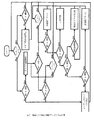
図7は、提案する発明の制御アルゴリズムの一例を示す。プログラマブルコントローラは、まず、コンプレッサがオフであるかどうかをチェックする。この場合、本発明によるデバイスは、温度差(DT)(測定された温度差)が(MTDC)(コンプレッサが稼働していないとき、運転中のクランクケースヒータが2つのセンサ間にもたらすべき最小温度差)より高いかどうかをチェックする。 FIG. 7 shows an example of the control algorithm of the proposed invention. The programmable controller first checks to see if the compressor is off. In this case, the device according to the invention has a temperature difference (DT) (measured temperature difference) of (MTDC) (the minimum temperature that a crankcase heater in operation should bring between two sensors when the compressor is not running. Check if it is higher than the difference).
温度差(DT)が(MTDC)以下であれば、モータを停止させるためのリレーが、所定時間、すなわち10分間に渡ってそのオフポジションに保持される。(DT)が(MTDC)より大きければ、コントローラプログラムは、プログラム開始へと指令される。 If the temperature difference (DT) is less than or equal to (MTDC), the relay for stopping the motor is held in its off position for a predetermined time, i.e. 10 minutes. If (DT) is greater than (MTDC), the controller program is instructed to start the program.
コンプレッサが始動していれば、コントローラは、直ちに温度差(DT)が(UTD)より大きいかどうかのチェックを開始し、大きくなければ、コントローラは、直ちにコンプレッサを所定の時間、すなわち5分間に渡って停止する。(DT)が(UTD)より大きければ、コントローラは、(DBCP)遅延タイマを開始し、かつこのタイマが終了するのを待つ。一方で、コントローラは、(DT)>(UTD)であるかどうかのチェックを続ける。 If the compressor is started, the controller immediately starts checking if the temperature difference (DT) is greater than (UTD), otherwise the controller immediately puts the compressor on for a given time, i.e. 5 minutes. And stop. If (DT) is greater than (UTD), the controller starts the (DBCP) delay timer and waits for this timer to end. On the other hand, the controller continues to check if (DT)> (UTD).
(DBCP)タイマが終了すると、コントローラは、(DT)が(OTD)より大きいかどうかをチェックし、大きければ、コントローラは、高過熱アラームを信号出力し、かつ必要に応じて、モータを停止することもできる。(DT)が(OTD)より小さければ、コントローラは、(DT)が(DTTD)(除霜トリガ温度差)より大きいかどうかをチェックする。(TDT)が(OTD)より小さい場合、コントローラは、システムが正常に動作していることを示す。 When the (DBCP) timer expires, the controller checks if (DT) is greater than (OTD), and if so, the controller signals a high overheat alarm and shuts down the motor if necessary. You can also do it. If (DT) is less than (OTD), the controller checks if (DT) is greater than (DTTD) (defrost trigger temperature difference). If (TDT) is less than (OTD), the controller indicates that the system is operating normally.
温度差(DT)が(DTTD)より小さければ、コントローラは、(DT)が(ATD)(アラーム温度差)より大きいかどうかをチェックし、大きければ、(TSLD)(最終除霜からの時間)が(MTBD)(連続する2つの除霜サイクル間の最小時間)より大きいかどうかをチェックし、大きければ、新しい除霜サイクルを起動する。 If the temperature difference (DT) is less than (DTTD), the controller checks if (DT) is greater than (ATD) (alarm temperature difference), and if so, (TSLD) (time since final defrost). Checks if is greater than (MTBD) (minimum time between two consecutive defrost cycles), and if so, initiates a new defrost cycle.
温度差(DT)が(ATD)(アラーム温度差)より小さければ、コントローラは、(DT)が(危険なほど低い過熱を示す)(UTD)より大きいかどうかをチェックする。大きければ、コントローラは、危険なほど低い過熱を示すアラームを起動する。大きくなければ、コントローラは、コンプレッサを停止する。 If the temperature difference (DT) is less than (ATD) (alarm temperature difference), the controller checks if (DT) is greater than (UTD) (indicating dangerously low overheating). If it is large, the controller will trigger an alarm indicating a dangerously low overheating. If not large, the controller will stop the compressor.
全てのパラメータは、コンプレッサのタイプ、動作範囲および温度センサの位置に依存して調整可能である。温度差(DT)は、上流温度センサにより測定される流入ガス温度の関数として設定することができる。パラメータの設定をより容易にするために、本発明によるデバイスには、測定された温度差を示すための2桁ディスプレイを追加することができる。冷却システムがその正常運転状態に達すると、その温度は、記録され、かつ図6の凡例に示すような全ての設定値の設定に使用され得る。 All parameters can be adjusted depending on the type of compressor, the operating range and the position of the temperature sensor. The temperature difference (DT) can be set as a function of the inflow gas temperature measured by the upstream temperature sensor. To make it easier to set the parameters, the device according to the invention can be added with a two digit display to show the measured temperature difference. Once the cooling system reaches its normal operating condition, its temperature can be recorded and used to set all the settings as shown in the legend of FIG.
先の段落で定義したような異なる温度(UTD)、(DTTD)、(ATD)の設定値を調整する近道は、各設定間のギャップを最大にするために、(NTD)を等しい4つの部分に分けることである。(UTD)は、(NTD)値の25%に、(ATD)は、(NTD)値の50%に、(DTTD)は、(NTD)値の75%に設定することができる。 The shortcut to adjusting different temperature (UTD), (DTTD), and (ATD) settings as defined in the previous paragraph is to have four parts equal to (NTD) to maximize the gap between each setting. It is to divide into. (UTD) can be set to 25% of the (NTD) value, (ATD) can be set to 50% of the (NTD) value, and (DTTD) can be set to 75% of the (NTD) value.
冷却システムが除霜サイクル用に装備されない場合、(NTD)は、等しい3つの部分に分けることができる。(UTD)は、(NTD)の33%に、(ATD)は、(NTD)の66%に設定することができる。 If the cooling system is not equipped for the defrost cycle, (NTD) can be divided into three equal parts. (UTD) can be set to 33% of (NTD) and (ATD) can be set to 66% of (NTD).
同じ論理により、(OTD)は、(NTD)値の125%に設定することができ、(UOTD)は、(NTD)値の150%に設定することができる。 By the same logic, (OTD) can be set to 125% of the (NTD) value and (UOTD) can be set to 150% of the (NTD) value.
システム観測によって、これらのパーセント値は、製造業者により、先の段落で説明したような設定推奨事項に従って微調整されてもよい。 By system observation, these percentages may be fine-tuned by the manufacturer according to the configuration recommendations as described in the previous paragraph.
さらに、(UTD)および(UOTD)は、対応するアラーム(ATD)および(OTD)が5分間持続すればコンプレッサを停止するタイマで置換することができる。 In addition, (UTD) and (UOTD) can be replaced by a timer that stops the compressor if the corresponding alarms (ATD) and (OTD) last for 5 minutes.
図8は、異なる電動機効率を備える半密閉型コンプレッサを用いた、異なる範囲(空調、冷蔵庫、冷凍庫)で論考した全てのパラメータ設定を纏めたものである。最適なパフォーマンスのためには、なおも冷却マシンのベンチテストによってこれらの値をチェックすべきである。 FIG. 8 summarizes all the parameter settings discussed in different ranges (air conditioning, refrigerator, freezer) using semi-sealed compressors with different motor efficiencies. For optimal performance, these values should still be checked by bench testing of the cooling machine.
大型コンプレッサの調整をより良くするためには、(空調範囲、冷蔵庫範囲または冷凍室範囲)と等価であるコンプレッサの動作範囲(高圧、中圧または低圧)を規定する吸込圧力に従って設定値を変更するために、低精度の圧力センサを追加することができる。 For better adjustment of large compressors, change the set value according to the suction pressure that defines the operating range (high pressure, medium pressure or low pressure) of the compressor, which is equivalent to (air conditioning range, refrigerator range or freezer range). Therefore, a low precision pressure sensor can be added.
使用するセンサが温度センサであるか、圧力センサであるかに関わらず、何れの場合も、その主たる機能は、コンプレッサが、高い温度差が予想される冷凍室範囲で動作しているか、中程度の温度差が予想される冷蔵庫範囲で動作しているか、最小の温度差が予想される空調範囲で動作しているかを検出することにある。 Regardless of whether the sensor used is a temperature sensor or a pressure sensor, its main function is whether the compressor is operating in the freezer range where high temperature differences are expected, or moderate. The purpose is to detect whether the temperature difference is operating in the expected refrigerator range or the minimum temperature difference is expected to be in the air conditioning range.
いずれの場合も、全ての設定値は、設計温度で動作する冷却システムの実際の測定値に基づくものであるべきである。 In either case, all settings should be based on actual measurements of the cooling system operating at the design temperature.
温度差は、特に密閉型コンプレッサの場合、ガス流通路およびコンプレッサの内部構造に起因して予測が困難である。各コンプレッサモデルは、正常運転状態で試験されるべきであり、正常運転温度差が記録されるべきである。 Temperature differences are difficult to predict due to the gas flow path and the internal structure of the compressor, especially in the case of closed compressors. Each compressor model should be tested under normal operating conditions and the normal operating temperature difference should be recorded.
さらに、特に下流温度センサが工場出荷時にピストン入口弁の近くに設置済みであり得る密閉型コンプレッサでは、コンプレッサ上のセンサの位置も、コンプレッサモデルに依存して最適化することができる。 Further, the position of the sensor on the compressor can also be optimized depending on the compressor model, especially in closed compressors where the downstream temperature sensor may have been installed near the piston inlet valve at the factory.
信頼性の高い非ドリフト測定システムを得るために、温度差は、1つのホイートストンブリッジ構成で接続される2つの温度センサにより、または直列に接続される2つの熱電対を用いて測定されることが可能である。 To obtain a reliable non-drift measurement system, the temperature difference can be measured by two temperature sensors connected in one Wheatstone bridge configuration or by two thermocouples connected in series. It is possible.
先行技術と比較した利点 Advantages compared to prior art
全ての熱生成コンポーネント(すなわち、密閉型および半密閉型コンプレッサの場合の電動機、密閉型コンプレッサの場合のピストン本体、および開放型コンプレッサの場合の吸込ガス熱交換器)の下流の冷媒ガスにおける液体を検出することによる、液体のフラッディングの防止。これらの熱生成コンポーネントは全て、大量の液体を蒸発させることができ、ガス流内にさほど液体がない場合にコンプレッサを保護する。これは、コンプレッサの上流のガス状態をチェックするシステムと比較して、重要でない頻繁なコンプレッサの停止を防止する。 Liquids in the refrigerant gas downstream of all heat generating components (ie, motors for closed and semi-closed compressors, piston bodies for closed compressors, and suction gas heat exchangers for open compressors). Prevention of liquid flooding by detection. All of these heat-generating components can evaporate large amounts of liquid and protect the compressor when there is not much liquid in the gas stream. This prevents frequent, insignificant compressor outages compared to systems that check the gas status upstream of the compressor.
1つのコンパレータと1つのリレーとを備える2つの温度センサから成るデバイスによる、液体フラッドバックの簡単かつ正確な検出。高度な電子機器および起動タイマは、不要である。非常に低コストであり得ることから、最も安価な小型コンプレッサにも設置することができる。 Easy and accurate detection of liquid floodback with a device consisting of two temperature sensors with one comparator and one relay. No advanced electronics and start-up timers are required. Since it can be very low cost, it can be installed even in the cheapest small compressor.
主たる測定は、2つの熱電対または単一のホイートストンブリッジに設置される任意の2つの熱センサを用いることによる、示差的な測定である。示差測定は、時間によるドリフトを生じにくい。 The main measurement is a differential measurement using two thermocouples or any two thermal sensors installed on a single Wheatstone bridge. The differential measurement is less likely to cause drift over time.
圧力センサおよび温度センサを用いて冷媒ガスの過熱が測定される場合、圧力センサは、時間によるドリフトなしに、0.1バールの精度で測定可能であるべきであり、しかも20バールまでの圧力および−40〜+20℃の可変温度に耐えることが可能であるべきである。全誤差は、圧力センサから生じる誤差、温度測定から生じる誤差および圧力温度飽和表または圧力温度飽和関数から生じる誤差の合計である。 When overheating of the refrigerant gas is measured using pressure and temperature sensors, the pressure sensor should be able to measure with an accuracy of 0.1 bar without drift over time, and pressures up to 20 bar and It should be able to withstand variable temperatures of -40 to + 20 ° C. The total error is the sum of the error from the pressure sensor, the error from the temperature measurement and the error from the pressure temperature saturation table or the pressure temperature saturation function.
定期的較正は不要。本発明によるデバイスにおいて、主たる温度測定は、時間に対して極めて安定していることが知られている温度差である。 No regular calibration required. In the device according to the invention, the main temperature measurement is the temperature difference known to be extremely stable over time.
高価な温度センサ、または高価な電子コンパレータは不要。測定における摂氏1度または2度の誤差は、デバイスの保護機能の有効性を減じない。 No need for expensive temperature sensors or expensive electronic comparators. An error of 1 or 2 degrees Celsius in the measurement does not diminish the effectiveness of the protective function of the device.
本発明によるデバイスは、冷媒飽和圧力−温度表または冷媒飽和圧力−温度関数を入力する必要なしに、異なる冷媒により動作する。これは、温度差(DT)がゼロであれば、飽和状態が示される、という事実に起因する。これは、単一成分であれ、混合物であれ、あらゆる冷媒について当てはまる。 Devices according to the invention operate with different refrigerants without the need to enter a refrigerant saturation pressure-temperature table or refrigerant saturation pressure-temperature function. This is due to the fact that if the temperature difference (DT) is zero, a saturated state is indicated. This is true for any refrigerant, single component or mixture.
本発明によるデバイスは、クランクケースヒータが故障している場合にコンプレッサが作動することを防止する。ある保護デバイスは、その最も単純な実施形態においてでさえも、コンプレッサへの液体の戻り、およびクランクケースヒータの故障からコンプレッサを保護する。2つのセンサを慎重に設置することにより、かつクランクケースヒータの故障によりコンプレッサが作動していないときに2つのセンサ間に温度差がない場合、本デバイスは、コンプレッサの運転を防止する。 The device according to the invention prevents the compressor from operating if the crankcase heater is out of order. Some protective devices, even in their simplest embodiments, protect the compressor from the return of liquid to the compressor and failure of the crankcase heater. By carefully installing the two sensors, and if there is no temperature difference between the two sensors when the compressor is not operating due to a crankcase heater failure, the device will prevent the compressor from running.
トラファグ(Trafag)製DTS391に使用されている機械的機構のような機械的差動サーモスタットを使用し、かつこれをコンプレッサ内部に埋め込むことも可能である。この場合、デバイスを作動させるための電力は、不要である。これは、電動機コイルを保護するためにほとんどのコンプレッサに設置される機械的熱保護に類似するものであり、一部の単相コンプレッサにおいて、電気接点は、電動機コイルと直列であって、全てがコンプレッサ内部に配線される。 It is also possible to use a mechanical differential thermostat such as the mechanical mechanism used in the Trafag DTS391 and to embed it inside the compressor. In this case, no power is required to operate the device. This is similar to the mechanical thermal protection installed in most compressors to protect the motor coil, and in some single-phase compressors the electrical contacts are in series with the motor coil, all in series. It is wired inside the compressor.
本発明によるデバイスは、氷の蓄積結果を監視していることから、除霜サイクルを遙かに効率的に起動するために使用することができる。通常、除霜サイクルは、下記のように起動される。
−システム状態とは無関係に、クロック(時計)による。この場合、多くの除霜サイクルは早期に起動されるか、または起動されるのが遅すぎる。クロックまたは固定タイマは、冷蔵庫および冷凍室において高頻度で使用される。
−必ずしも除霜サイクル開始の目印(兆候)ではない低圧に基づく低蒸発圧力圧力スイッチ(pressostat)による。低圧は、蒸発器を介する低い流体温度、または少ない冷媒注入に起因する可能性があるからである。
−氷の厚さコントローラによる。氷の厚さは、不均一である可能性もあり、氷の厚さは、除霜サイクルを起動する誤った目印(兆候)となり得ることが分かっている。
Since the device according to the invention monitors the result of ice accumulation, it can be used to initiate the defrost cycle much more efficiently. Normally, the defrost cycle is started as follows.
-Depends on the clock, regardless of system state. In this case, many defrost cycles are started early or too late. Clocks or fixed timers are frequently used in refrigerators and freezer compartments.
-By a low evaporative pressure pressure switch (pressostat) based on low pressure, which is not necessarily a sign of the start of the defrost cycle. The low pressure can be due to low fluid temperature through the evaporator, or low refrigerant injection.
-Depends on the ice thickness controller. Ice thickness can also be non-uniform, and it has been found that ice thickness can be a false indicator (sign) of initiating a defrost cycle.
本発明によるデバイスは、過剰な過熱状態を検出することができ、かつアラームを送信する、または必要に応じてコンプレッサを停止することもできる。コンプレッサの停止は、アラームの設定値より高い過熱状態で設定することができ、または、アラーム状態が、ある所定時間(すなわち、5分)を超えて持続する場合タイマを用いることによって設定することができる。 Devices according to the invention can detect excessive overheating conditions and can also send alarms or shut down the compressor if necessary. The compressor stop can be set in an overheated state higher than the alarm set value, or can be set by using a timer if the alarm state persists for more than a predetermined time (ie, 5 minutes). can.
これは、ほぼ全てのコンプレッサにおいて固定設定で設置される、吐出温度およびモータ巻線温度の保護に対する追加的な保護である。設定は、コンプレッサ吐出弁、冷媒オイルまたは電動機巻線のいずれかが許容できる最高温度で固定される。本発明によるデバイスにおいて、(OTD)値は、冷却システムの設計された動作温度に従って調整される。ほとんどの場合、冷却システムの設計された動作温度は、コンプレッサの最高動作温度より低い。システムの設計された動作温度のパラメータの使用は、アラームを送信する機会、または、吐出弁もしくは電動機巻線において過剰温度に達する前に、コンプレッサを停止する機会さえも与える。例えば、同じ半密閉型コンプレッサを、冷凍システムおよびチラーシステムにおいて使用することができる。吐出温度および電動機巻線保護は、製造業者により、冷凍庫の動作温度、概して120℃超、に設定される。コンプレッサがチラーとして使用される場合、吐出温度を、100℃未満に設定することが可能であり、温度が100℃を超える場合、これは、システムに何らかの問題があることを意味し、システムは、チェックされるべきである。 This is an additional protection against discharge temperature and motor winding temperature protection, which is installed in a fixed setting on almost all compressors. The setting is fixed at the maximum temperature that either the compressor discharge valve, the refrigerant oil or the motor windings can tolerate. In the device according to the invention, the (OTD) value is adjusted according to the designed operating temperature of the cooling system. In most cases, the designed operating temperature of the cooling system is lower than the maximum operating temperature of the compressor. The use of the system's designed operating temperature parameters gives the opportunity to send an alarm, or even stop the compressor before the excess temperature is reached in the discharge valve or motor winding. For example, the same semi-sealed compressor can be used in freezing and chiller systems. The discharge temperature and motor winding protection are set by the manufacturer to the operating temperature of the freezer, generally above 120 ° C. When the compressor is used as a chiller, the discharge temperature can be set below 100 ° C, and if the temperature exceeds 100 ° C, this means that there is something wrong with the system, the system Should be checked.
本発明によるデバイスは、コンプレッサ、特に密閉型および半密閉型コンプレッサ、の低い温度範囲を拡大することができる。コンプレッサが低い蒸発温度で、ひいては低い蒸発圧力および低減された冷媒質量の流れ(電動機を冷却するため)で動作しているとき、高い過熱が吐出温度および電動機巻線温度を危険なほどに高める。ピストンの入口弁近くの過熱を制御することによって、過熱を最小限に抑えることができる。低い過熱は、吐出温度および電動機巻線温度を下げる。この特徴の利益を得るために、膨張弁を制御するためのPIDを備える実施形態が利用されるべきである。 The device according to the invention can extend the low temperature range of compressors, especially closed and semi-closed compressors. When the compressor is operating at a low evaporation temperature, and thus with a low evaporation pressure and a reduced flow of refrigerant mass (to cool the motor), high overheating can dangerously increase the discharge temperature and the motor winding temperature. Overheating can be minimized by controlling overheating near the inlet valve of the piston. Low overheating lowers the discharge temperature and the motor winding temperature. In order to benefit from this feature, embodiments with a PID for controlling the expansion valve should be utilized.
産業上の用途 Industrial use
本発明は、主として冷却およびヒートポンプシステムにおいて使用することができる。冷却システムの例は、次の通りである。
−冷蔵庫
−スプリットシステムの空調、冷房およびヒートポンプ
−チラー
−冷蔵倉庫および冷凍室
−ブラストクーラおよびブラストフリーザ
−ウォータークーラおよび製氷機
−カーエアコンシステム
The present invention can be used primarily in cooling and heat pump systems. An example of a cooling system is as follows.
-Refrigerator-Split system air conditioning, cooling and heat pump-Chiller-Refrigerator and freezer room-Blast cooler and blast freezer-Water cooler and ice machine-Car air conditioning system
説明した本発明の特定の実施形態が、本発明の原理の所定の用途を単に例示するものであることは、理解されるべきである。本明細書に記述されている本発明の計装および方法に対しては、本発明の精神および範囲を逸脱することなく、多くの変更が行われてもよい。 It should be understood that the particular embodiments of the invention described merely illustrate certain uses of the principles of the invention. Many changes may be made to the instrumentation and methods of the invention described herein without departing from the spirit and scope of the invention.
Claims (9)
Applications Claiming Priority (2)
| Application Number | Priority Date | Filing Date | Title |
|---|---|---|---|
| US201662319335P | 2016-04-07 | 2016-04-07 | |
| PCT/GR2017/000015 WO2017175014A1 (en) | 2016-04-07 | 2017-03-24 | Refrigeration system control and protection device |
Publications (3)
| Publication Number | Publication Date |
|---|---|
| JP2019533792A JP2019533792A (en) | 2019-11-21 |
| JP2019533792A5 JP2019533792A5 (en) | 2020-04-30 |
| JP6959660B2 true JP6959660B2 (en) | 2021-11-02 |
Family
ID=58994955
Family Applications (1)
| Application Number | Title | Priority Date | Filing Date |
|---|---|---|---|
| JP2019503795A Active JP6959660B2 (en) | 2016-04-07 | 2017-03-24 | Cooling system control and protection device |
Country Status (6)
| Country | Link |
|---|---|
| US (1) | US10876778B2 (en) |
| EP (1) | EP3446053B1 (en) |
| JP (1) | JP6959660B2 (en) |
| KR (1) | KR102319725B1 (en) |
| DK (1) | DK3446053T3 (en) |
| WO (1) | WO2017175014A1 (en) |
Families Citing this family (8)
| Publication number | Priority date | Publication date | Assignee | Title |
|---|---|---|---|---|
| US10782057B2 (en) | 2017-12-29 | 2020-09-22 | Johnson Controls Technology Company | Motor temperature control technique with temperature override |
| WO2021030169A1 (en) | 2019-08-09 | 2021-02-18 | Carrier Corporation | Cooling system and method of operating a cooling system |
| CN111578442B (en) * | 2020-05-12 | 2022-06-17 | 宁波奥克斯电气股份有限公司 | Liquid return prevention control method and device for compressor and air conditioner |
| JP7505919B2 (en) | 2020-05-29 | 2024-06-25 | 日鉄テックスエンジ株式会社 | Factory equipment monitoring system, factory equipment monitoring method and program |
| IT202100007316A1 (en) * | 2021-03-25 | 2022-09-25 | Ariston S P A | METHOD FOR MANAGING A HEAT PUMP OPERATING WITH AN OPERATING FLUID WITH LOW ENVIRONMENTAL IMPACT |
| CN113758048B (en) * | 2021-08-12 | 2024-04-19 | 深圳市派沃新能源科技股份有限公司 | Air source heat pump low temperature protection system |
| US20230064936A1 (en) * | 2021-08-26 | 2023-03-02 | Charles Cluff | Method of operating a heat pump system |
| CN115046364A (en) * | 2022-05-13 | 2022-09-13 | 浙江劳达制冷科技有限公司 | Cold and hot accuse temperature unit of new forms of energy motor test |
Family Cites Families (19)
| Publication number | Priority date | Publication date | Assignee | Title |
|---|---|---|---|---|
| DE3413535C1 (en) | 1984-04-11 | 1985-11-14 | Danfoss A/S, Nordborg | Measuring device for determining a proportion of liquid in the refrigerant |
| US5209076A (en) | 1992-06-05 | 1993-05-11 | Izon, Inc. | Control system for preventing compressor damage in a refrigeration system |
| US5666815A (en) | 1994-11-18 | 1997-09-16 | Cooper Instrument Corporation | Method and apparatus for calculating super heat in an air conditioning system |
| JP3706445B2 (en) * | 1996-09-26 | 2005-10-12 | 三洋電機株式会社 | Air conditioner control device |
| US6578373B1 (en) | 2000-09-21 | 2003-06-17 | William J. Barbier | Rate of change detector for refrigerant floodback |
| KR100405986B1 (en) * | 2001-02-26 | 2003-11-15 | 엘지전자 주식회사 | Air conditioning system and method |
| US6539734B1 (en) | 2001-12-10 | 2003-04-01 | Carrier Corporation | Method and apparatus for detecting flooded start in compressor |
| US6886354B2 (en) | 2003-04-04 | 2005-05-03 | Carrier Corporation | Compressor protection from liquid hazards |
| JP4459776B2 (en) | 2004-10-18 | 2010-04-28 | 三菱電機株式会社 | Heat pump device and outdoor unit of heat pump device |
| WO2010143343A1 (en) * | 2009-06-12 | 2010-12-16 | パナソニック株式会社 | Refrigeration cycle device |
| EP2524829B1 (en) * | 2010-01-15 | 2017-09-13 | Mitsubishi Heavy Industries, Ltd. | Vehicle air-conditioning system and driving control method therefor |
| WO2012027241A1 (en) | 2010-08-23 | 2012-03-01 | Carrier Corporation | Electric expansion valve control for a refrigeration system |
| CN104797893B (en) | 2012-11-21 | 2016-08-24 | 三菱电机株式会社 | Conditioner |
| JP2014119157A (en) | 2012-12-14 | 2014-06-30 | Sharp Corp | Heat pump type heating device |
| US9194393B2 (en) * | 2013-04-12 | 2015-11-24 | Emerson Climate Technologies, Inc. | Compressor with flooded start control |
| WO2015045129A1 (en) * | 2013-09-27 | 2015-04-02 | 三菱電機株式会社 | Oil surface detection device and refrigerating air conditioner equipped with same |
| JP6297817B2 (en) * | 2013-11-08 | 2018-03-20 | 東日本旅客鉄道株式会社 | Maintenance time determination method for vehicle air conditioner |
| EP3115717A4 (en) * | 2014-02-18 | 2018-02-28 | Toshiba Carrier Corporation | Refrigeration cycle device |
| JP6492358B2 (en) * | 2014-11-26 | 2019-04-03 | 三菱重工サーマルシステムズ株式会社 | Control device, air conditioner and control method |
-
2017
- 2017-03-24 EP EP17727682.1A patent/EP3446053B1/en active Active
- 2017-03-24 US US16/091,158 patent/US10876778B2/en active Active
- 2017-03-24 KR KR1020187032259A patent/KR102319725B1/en active IP Right Grant
- 2017-03-24 DK DK17727682.1T patent/DK3446053T3/en active
- 2017-03-24 WO PCT/GR2017/000015 patent/WO2017175014A1/en active Application Filing
- 2017-03-24 JP JP2019503795A patent/JP6959660B2/en active Active
Also Published As
| Publication number | Publication date |
|---|---|
| US20200200458A1 (en) | 2020-06-25 |
| KR102319725B1 (en) | 2021-11-03 |
| US10876778B2 (en) | 2020-12-29 |
| EP3446053A1 (en) | 2019-02-27 |
| WO2017175014A4 (en) | 2017-11-09 |
| WO2017175014A1 (en) | 2017-10-12 |
| KR20180132838A (en) | 2018-12-12 |
| JP2019533792A (en) | 2019-11-21 |
| EP3446053B1 (en) | 2024-05-08 |
| DK3446053T3 (en) | 2024-07-08 |
Similar Documents
| Publication | Publication Date | Title |
|---|---|---|
| JP6959660B2 (en) | Cooling system control and protection device | |
| US8109104B2 (en) | System and method for detecting decreased performance in a refrigeration system | |
| KR101137740B1 (en) | System and method for calibrating parameters for a refrigeration system with a variable speed compressor | |
| US10627146B2 (en) | Liquid slugging detection and protection | |
| US20090090117A1 (en) | System and method for monitoring overheat of a compressor | |
| EP3273179B1 (en) | Heat pump | |
| US10156396B2 (en) | System for operating an HVAC system having tandem compressors | |
| US20160238332A1 (en) | Heat Exchanger Fault Diagnostic | |
| CN106766444B (en) | The liquid impact prevention control method and control device and air-conditioning system of air-conditioning system | |
| JP6177218B2 (en) | Air conditioner | |
| RU2409794C1 (en) | Refrigerator | |
| CN110836519B (en) | Air conditioner refrigerant leakage detection method and detection system | |
| JP5541945B2 (en) | Gas leak detection method | |
| US9829229B2 (en) | System and method for detecting low refrigerant charge in a refrigeration system | |
| JP6587131B2 (en) | Refrigeration system | |
| CA2885449C (en) | System for controlling operation of an hvac system having tandem compressors | |
| CN110345705B (en) | Optimal control method and device for temperature control valve of refrigeration system and refrigeration system | |
| JPH10103833A (en) | Refrigerator for store | |
| JP6610998B2 (en) | Refrigeration system | |
| JPS5842845Y2 (en) | Gas leak detector for refrigeration equipment |
Legal Events
| Date | Code | Title | Description |
|---|---|---|---|
| A521 | Request for written amendment filed |
Free format text: JAPANESE INTERMEDIATE CODE: A821 Effective date: 20181129 |
|
| RD01 | Notification of change of attorney |
Free format text: JAPANESE INTERMEDIATE CODE: A7426 Effective date: 20181129 |
|
| A521 | Request for written amendment filed |
Free format text: JAPANESE INTERMEDIATE CODE: A523 Effective date: 20190828 |
|
| A521 | Request for written amendment filed |
Free format text: JAPANESE INTERMEDIATE CODE: A523 Effective date: 20200323 |
|
| A621 | Written request for application examination |
Free format text: JAPANESE INTERMEDIATE CODE: A621 Effective date: 20200323 |
|
| A131 | Notification of reasons for refusal |
Free format text: JAPANESE INTERMEDIATE CODE: A131 Effective date: 20210323 |
|
| A521 | Request for written amendment filed |
Free format text: JAPANESE INTERMEDIATE CODE: A523 Effective date: 20210611 |
|
| TRDD | Decision of grant or rejection written | ||
| A01 | Written decision to grant a patent or to grant a registration (utility model) |
Free format text: JAPANESE INTERMEDIATE CODE: A01 Effective date: 20210907 |
|
| A61 | First payment of annual fees (during grant procedure) |
Free format text: JAPANESE INTERMEDIATE CODE: A61 Effective date: 20211001 |
|
| R150 | Certificate of patent or registration of utility model |
Ref document number: 6959660 Country of ref document: JP Free format text: JAPANESE INTERMEDIATE CODE: R150 |