JP6958790B2 - Mammography interpretation device and mammography interpretation method - Google Patents
Mammography interpretation device and mammography interpretation method Download PDFInfo
- Publication number
- JP6958790B2 JP6958790B2 JP2019075004A JP2019075004A JP6958790B2 JP 6958790 B2 JP6958790 B2 JP 6958790B2 JP 2019075004 A JP2019075004 A JP 2019075004A JP 2019075004 A JP2019075004 A JP 2019075004A JP 6958790 B2 JP6958790 B2 JP 6958790B2
- Authority
- JP
- Japan
- Prior art keywords
- image
- simulated
- screen
- mammography
- luminance
- Prior art date
- Legal status (The legal status is an assumption and is not a legal conclusion. Google has not performed a legal analysis and makes no representation as to the accuracy of the status listed.)
- Active
Links
- 238000009607 mammography Methods 0.000 title claims description 106
- 238000000034 method Methods 0.000 title claims description 39
- 235000019557 luminance Nutrition 0.000 claims description 59
- 230000003902 lesion Effects 0.000 claims description 50
- 210000000481 breast Anatomy 0.000 claims description 33
- 230000015572 biosynthetic process Effects 0.000 claims description 29
- 238000003786 synthesis reaction Methods 0.000 claims description 29
- 230000008569 process Effects 0.000 claims description 21
- 238000012545 processing Methods 0.000 claims description 15
- 230000002194 synthesizing effect Effects 0.000 claims description 8
- 238000003672 processing method Methods 0.000 claims description 7
- 210000005075 mammary gland Anatomy 0.000 description 42
- 239000002131 composite material Substances 0.000 description 25
- 206010028980 Neoplasm Diseases 0.000 description 14
- 230000006870 function Effects 0.000 description 13
- 238000010521 absorption reaction Methods 0.000 description 9
- 206010006187 Breast cancer Diseases 0.000 description 8
- 208000026310 Breast neoplasm Diseases 0.000 description 8
- PEDCQBHIVMGVHV-UHFFFAOYSA-N Glycerine Chemical compound OCC(O)CO PEDCQBHIVMGVHV-UHFFFAOYSA-N 0.000 description 7
- 230000005540 biological transmission Effects 0.000 description 6
- 238000010586 diagram Methods 0.000 description 6
- 238000003384 imaging method Methods 0.000 description 6
- 238000007689 inspection Methods 0.000 description 6
- 238000012216 screening Methods 0.000 description 6
- 210000001519 tissue Anatomy 0.000 description 6
- 238000004891 communication Methods 0.000 description 4
- 230000000694 effects Effects 0.000 description 4
- 210000000577 adipose tissue Anatomy 0.000 description 3
- 239000003550 marker Substances 0.000 description 3
- 230000004044 response Effects 0.000 description 3
- 230000000007 visual effect Effects 0.000 description 3
- 230000006835 compression Effects 0.000 description 2
- 238000007906 compression Methods 0.000 description 2
- 230000034994 death Effects 0.000 description 2
- 231100000517 death Toxicity 0.000 description 2
- 238000001514 detection method Methods 0.000 description 2
- 238000005516 engineering process Methods 0.000 description 2
- 230000007246 mechanism Effects 0.000 description 2
- 238000002360 preparation method Methods 0.000 description 2
- 230000005856 abnormality Effects 0.000 description 1
- 230000003416 augmentation Effects 0.000 description 1
- 238000004364 calculation method Methods 0.000 description 1
- 238000012790 confirmation Methods 0.000 description 1
- 238000007796 conventional method Methods 0.000 description 1
- 238000012937 correction Methods 0.000 description 1
- 230000003247 decreasing effect Effects 0.000 description 1
- 238000012850 discrimination method Methods 0.000 description 1
- 229940079593 drug Drugs 0.000 description 1
- 239000003814 drug Substances 0.000 description 1
- 230000006872 improvement Effects 0.000 description 1
- 230000001788 irregular Effects 0.000 description 1
- 210000004072 lung Anatomy 0.000 description 1
- 238000002156 mixing Methods 0.000 description 1
- 239000000203 mixture Substances 0.000 description 1
- 230000002093 peripheral effect Effects 0.000 description 1
- 230000009467 reduction Effects 0.000 description 1
- 230000009291 secondary effect Effects 0.000 description 1
- 238000004904 shortening Methods 0.000 description 1
- 238000004088 simulation Methods 0.000 description 1
- 210000003625 skull Anatomy 0.000 description 1
- 210000002784 stomach Anatomy 0.000 description 1
- 230000009466 transformation Effects 0.000 description 1
- 238000010626 work up procedure Methods 0.000 description 1
Images


Landscapes
- Image Processing (AREA)
- Apparatus For Radiation Diagnosis (AREA)
Description
本発明は、X線マンモグラフィによって収集された乳房のマンモグラフィ画像を読影するための表示器と入力器とを備えたワークステーションに関する。 The present invention relates to a workstation equipped with an indicator and an input device for interpreting a mammographic image of a breast collected by X-ray mammography.
近年富に、X線マンモグラフィによる乳がん検診の重要性が増している。それは、日本のみならず、世界的にも乳癌罹患率および死亡数は増加傾向にあり、女性の30歳から64歳では乳がんが死亡原因のトップとなっているからである。 In recent years, the importance of breast cancer screening by X-ray mammography has increased. This is because the prevalence of breast cancer and the number of deaths are increasing not only in Japan but also in the world, and breast cancer is the leading cause of death among women aged 30 to 64 years.
この中で、欧米では乳がんの罹患率は増加しているが死亡率は減少してきており、これはマンモグラフィによる乳がん検診の導入と60〜80%という高い検診率による乳がんの早期発見が寄与していると考えられている。一方、日本では国が定期的な検診受診を推奨しているものの、乳がん検診受診率は低く、年々死亡率は増加傾向にある。 Among these, in Europe and the United States, the morbidity rate of breast cancer is increasing, but the mortality rate is decreasing, which is contributed by the introduction of breast cancer screening by mammography and the early detection of breast cancer by the high screening rate of 60 to 80%. It is believed that there is. On the other hand, in Japan, although the national government recommends regular screening, the breast cancer screening rate is low and the mortality rate is increasing year by year.
日本人は欧米人に比べて高濃度乳腺の割合が高く、近年のマンモグラフィによる乳がん検診の普及に伴い、高濃度乳腺の問題、即ち、病変が高濃度乳腺に隠れてしまい、腫瘤病変の発見し難くなるという問題がクローズアップされている。つまり、マンモグラフィでは乳腺の構成(脂肪性、乳腺散在、不均一高濃度、きわめて高濃度)により病変が正常乳腺に隠されてしまう危険性が異なり、特に石灰化病変に比べ腫瘤病変はその危険性が高くなる。 Compared to Westerners, Japanese have a higher proportion of high-concentration mammary glands, and with the spread of breast cancer screening by mammography in recent years, the problem of high-concentration mammary glands, that is, lesions are hidden by high-concentration mammary glands, and mass lesions are discovered. The problem of difficulty is highlighted. In other words, in mammography, the risk of lesions being hidden in normal mammary glands differs depending on the composition of the mammary glands (fatty, scattered mammary glands, heterogeneous high concentration, extremely high concentration), especially tumor lesions compared to calcified lesions. Will be higher.
近年ではトモシンセシスに対応した撮影装置が登場し、乳腺の重なりが少ない断層画像が得られるようになり、より精度が高く正常乳腺なのかどうかの判定が可能となっている。しかしながら、トモシンセシス対応の装置は高価な上に、撮影時間や被ばく量の増加など患者への負担も増え、さらに生成される断層画像の枚数が多く読影医への読影作業の負担も高い。 In recent years, an imaging device compatible with tomosynthesis has appeared, and it has become possible to obtain tomographic images with less overlap of mammary glands, and it is possible to determine whether or not the mammary glands are normal with higher accuracy. However, a device compatible with tomosynthesis is expensive, and the burden on the patient increases due to an increase in imaging time and exposure dose, and the number of tomographic images generated is large, which imposes a heavy burden on the image interpreting doctor.
このような状況において、マンモグラフィ画像の読影作業の効率化を図ることを目的として、特許文献1に記載の医用画像表示装置及びマンモグラフィ装置が提案されている。この特許文献1の医用画像表示装置は、マンモグラフィ装置に一体に装備されている。これにより、マンモグラフィ装置は、断層画像ごとの断層位置と乳腺量との対応関係を表すグラフ情報を表示し、表示された断層画像の断層位置を表すグラフマーカGMをグラフ情報G1に重畳表示する。このため、読影医等の画像参照者は、グラフマーカGMが表示された位置を視認して、表示された断層画像の乳腺量を容易に把握しながら読影を行うことができる。これにより、読影効率の向上を図らんとするものである。
In such a situation, the medical image display device and the mammography device described in
しかしながら、上述した特許文献1に記載の医用画像表示装置では、表示された断層画像の断層位置を表すグラフマーカGMをグラフ情報G1に重畳表示するものの、読影医が、乳腺の影に腫瘤や腫瘍等の病変が紛れ込んでいないか、または隠れていないかという観点からマンモグラフィ画像を1枚ごとに目視観察する読影の効率化及び容易化には何ら関与しない。
However, in the medical image display device described in
勿論、ここで言う「読影の効率化及び容易化」とは、単に読影作業の短時間化を図るだけではなく、より小さいサイズの病変まで確実に読影して診断精度の向上に繋げることを言う。このため、「少なくともこれ以上のサイズの病変」を見逃さないようにするためのマーキングの仕組みも併せ持つことが望まれる。このため、より高い読影精度を確保可能な仕組みを持つと共に、読影作業のスループットを上げて読影医の読影作業の労力負担を軽減することが望まれる。 Of course, "improving and facilitating image interpretation" here means not only shortening the image interpretation work, but also reliably interpreting even smaller lesions and improving diagnostic accuracy. .. For this reason, it is desirable to also have a marking mechanism so as not to overlook "lesions of at least larger size". Therefore, it is desired to have a mechanism capable of ensuring higher image interpretation accuracy, increase the throughput of the image interpretation work, and reduce the labor burden of the image interpretation work of the image interpretation doctor.
そこで、本発明は、上述した従来のマンモグラフィ画像の読影作業が抱える状況に鑑みて、より高い読影精度を確保することができ、且つ、読影医にとっても読影作業のスループットを上げることができると共に読影作業の労力負担を軽減することができるマンモグラフィ用の読影装置及び読影方法を提供する、ことをその目的とする。 Therefore, in view of the situation of the conventional mammography image interpretation work described above, the present invention can secure higher image interpretation accuracy, increase the throughput of the image interpretation work for the image interpretation doctor, and interpret the image. An object of the present invention is to provide an image interpretation device and an image interpretation method for mammography that can reduce the labor burden of work.
上記目的を達成するため、本発明に係るマンモグラフィ読影装置は、
モニタと、
X線マンモグラフィ装置により撮影された人体の乳房の2次元のX線画像を前記モニタの画面に表示する画像表示手段と、
前記画像表示手段により前記X線画像が表示された前記モニタの前記画面に、特定の形状及びサイズを有し且つ想定した病変部を模擬的に示す模擬領域を当該画面上で移動可能な状態で設定し表示する模擬領域設定表示手段と、
前記画面上で前記模擬領域を形成する複数の画素を特定する画素特定手段と、
前記画素特定手段により特定された前記複数の画素の少なくとも一部の複数の原輝度と、当該少なくとも一部の複数の画素に、前記模擬領域の広がりを特徴付ける処理を施して得た輝度とを合成する輝度合成手段と、
前記輝度合成手段により合成された輝度を有する前記模擬領域を、前記X線画像に重畳して表示可能なように前記モニタの前記画面に表示する重畳表示手段と、
を備えたことを特徴とする。
In order to achieve the above object, the mammography image interpretation device according to the present invention is
With a monitor
An image display means for displaying a two-dimensional X-ray image of the human breast taken by an X-ray mammography apparatus on the screen of the monitor, and an image display means.
On the screen of the monitor on which the X-ray image is displayed by the image display means, a simulated area having a specific shape and size and simulating an assumed lesion portion is movable on the screen. a simulated area setting display device for setting display,
Pixel specifying means for specifying a plurality of pixels forming the simulated area on the screen, and
A combination of a plurality of original luminances of at least a part of the plurality of pixels specified by the pixel specifying means and a luminance obtained by subjecting the at least a part of the plurality of pixels to a process for characterizing the spread of the simulated area. Luminance synthesis means and
The simulated area, and table Shimesuru superimposed display means to the screen of the monitor so as to be displayed superimposed on the X-ray image with a synthesized luminance by the luminance synthesizing unit,
It is characterized by being equipped with.
このように、病変を模した模擬領域が乳房のX線画像に、その模擬領域の広がりを特徴付けた輝度で重畳表示可能になる。このため、ユーザ(読影医など)は、そのように重畳表示された模擬領域を関心ある部位まで移動させることで、その部位において、模擬領域の広がり、即ち、腫瘤等の病変の見逃したくないサイズ(広がり)と乳腺組織の関心部位の広がりとを比較して観察してみることができる。具体的には、病変が乳腺組織の一部の関心部位に隠れてしまっていないか、物差しを当てたのと同等の状態を画像上で容易に且つ迅速に得られる。このため、マンモグラフィ画像の読影をより精度良くかつ迅速に行うことができ、読影スループット向上に貢献でき、また読影者の読影作業の労力軽減にも寄与可能になる。
In this way, the simulated area that imitates the lesion can be superimposed and displayed on the X-ray image of the breast with the brightness that characterizes the extent of the simulated area. For this reason, the user (such as an image interpreter) moves the simulated area superposed in this way to a site of interest, so that the simulated area expands at that site, that is, a size that does not want to overlook a lesion such as a tumor. It is possible to compare and observe (spread) with the spread of the site of interest in the mammary gland tissue. Specifically, the lesion is not hidden in a part of the mammary gland tissue of interest, or a state equivalent to that of a ruler can be easily and quickly obtained on the image. Therefore, the interpretation of the mammography image can be performed more accurately and quickly, which can contribute to the improvement of the interpretation throughput and also contribute to the reduction of the labor of the interpretation work of the interpreter.
好適な一例として、前記模擬領域は、オペレータが前記X線画像上で病変の見過しを防止するように予め設定された所望サイズに設定されている。
As a preferred example, the simulated area is set to a desired size preset so that the operator prevents the lesion from being overlooked on the X-ray image.
また、別の好適な一例として、前記模擬領域設定手段は、前記モニタの画面上に表示する前記模擬領域のサイズ及び形状のうちの少なくとも一方を変更可能な領域変更手段を備える。
Further, as another preferable example, the simulated area setting means includes an area changing means capable of changing at least one of the size and shape of the simulated area displayed on the screen of the monitor.
また、本発明に係るマンモグラフィ読影方法は、X線マンモグラフィ装置により撮影された人体の乳房の2次元のX線画像をモニタの画面に表示し、前記X線画像が表示された前記モニタの前記画面に、特定の形状を有し且つ想定した病変部の大きさ(及び広がり)を模擬的に示す模擬領域を、当該X線画像を探索するために当該画面上で移動可能なように設定して表示し、前記模擬領域を形成する複数の画素を特定し、前記特定された前記複数の画素の少なくとも一部の複数の原輝度と、当該少なくとも一部の複数の画素に、前記模擬領域の広がりを特徴付ける処理を施して得た輝度とを合成し、前記合成された輝度を有する前記模擬領域を、前記X線画像に重畳して表示可能なように前記モニタの前記画面に表示する、
ことを特徴とする。
Further, in the mammography interpretation method according to the present invention, a two-dimensional X-ray image of a human breast taken by an X-ray mammography apparatus is displayed on a monitor screen, and the screen of the monitor on which the X-ray image is displayed is displayed. in the simulated area showing simulated the size of and assumed lesion has a specific shape (and spread), the set Mr. so as to be movable on the screen in order to explore the X-ray image display Te, and the identifying a plurality of pixels forming the simulated region, a plurality of original brightness of at least some of said plurality of pixels said identified, to the at least a portion of the plurality of pixels, the simulated area synthesizing the luminance obtained by applying the process of characterizing the spread, the simulated area, displayed on the screen of the monitor so as to be displayed superimposed on the X-ray image with the synthesized intensity,
It is characterized by that.
この読影方法によっても、上述した読影装置が提供できる作用効果と同等の作用効果を発揮することができる。
なお、上述したマンモグラフィ読影装置及びマンモグラフィ読影方法に係る特徴を機能的になす構成は、マンモグラフィ読影用のプログラムを予め記録可能な記録媒体、及び、そのプログラムとしても同様に提供できる。
This image interpretation method can also exert an effect equivalent to the effect that the above-mentioned image interpretation device can provide.
It should be noted that the above-described mammography interpretation apparatus and mammography interpretation method-related features can be functionally provided as a recording medium on which a mammography interpretation program can be recorded in advance and the program thereof.
添付図面において、
以下、添付図面に従って、本発明の実施形態に係るマンモグラフィ読影装置及びマンモグラフィ読影方法を説明する。 Hereinafter, the mammography image interpretation device and the mammography image interpretation method according to the embodiment of the present invention will be described with reference to the accompanying drawings.
[第1の実施形態]
図1〜図10、図13を参照して、第1の実施形態に係るマンモグラフィ読影装置及びマンモグラフィ読影方法を説明する。
[First Embodiment]
The mammography image interpretation device and the mammography image interpretation method according to the first embodiment will be described with reference to FIGS. 1 to 10 and 13.
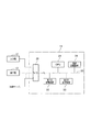
このマンモグラフィ読影装置及びマンモグラフィ読影方法は、図1に示すように、マンモグラフィ装置1により撮影されたマンモグラフィ画像を画像サーバ2を介して受信する読影用ワークステーション(以下、単にワークステーションと呼ぶ)3により実施されている。
As shown in FIG. 1, the mammography image interpretation device and the mammography image interpretation method are performed by an image interpretation workstation (hereinafter, simply referred to as a workstation) 3 that receives a mammography image taken by the
このワークステーション3は、コンピュータによる各種の既定プログラムの演算を行う演算装置11と、この演算装置11に通信可能に接続された、マンマシンインターフェースとして機能する入力器12及び表示器13とを備える。
The
マンモグラフィ装置1は、従来よく知られている構成を有し、人体の乳房を圧迫板で圧迫した状態で、その圧迫方向においてX線照射及びX線検出を行って得たX線透過画像を収集するように構成されている。このX線透過画像は、乳房内の各種組織が呈するX線の減弱度合を例えばグレイレベルの階調で表現した2次元画像である。このX線透過画像には単純撮影された2次元画像のみならず、トモシンセシス撮影(乳房が圧迫された状態で異なるX線の入射角で複数回撮影)で収集された複数のフレームデータをシフト加算法(shift and add)やフィルタ逆投影法(Filtered Back Projection)などの手法を使って再構成し、その位置にある一定の断層厚さの領域を焦点化した再構成画像も含まれる。
The
このマンモグラフィ撮影は、一般的には、乳房のブラインドエリアを極力少なくするため、MLO(Medio‐Lateral Oblique)とCC(Cranio‐Caudal)の2方向で実施することが多い。2方向撮影の場合、乳腺組織を圧迫して広げる方向が異なるため、読影時に、病変部位が乳腺組織に隠されてしまい、見逃してしまう可能性をある程度低減できる。また、読影時には、左右の乳腺構造の比較によっても異常を検知できる。 In general, this mammography is often performed in two directions, MLO (Mediao-Lateral Skull) and CC (Cranio-Caudal), in order to minimize the blind area of the breast. In the case of two-way imaging, since the direction in which the mammary gland tissue is compressed and expanded is different, the possibility that the lesion site is hidden by the mammary gland tissue during image interpretation and is overlooked can be reduced to some extent. In addition, at the time of image interpretation, an abnormality can be detected by comparing the left and right mammary gland structures.
このマンモグラフィ装置1により撮影されたマンモグラフィ画像は、一例として、通信網CM1(インターネット等)を介して検査情報(患者名、患者ID、撮影日時、撮影条件など)と共に画像サーバ2に送られ、画像サーバ2に保管される。この画像サーバ2は、例えばPACS(画像保管・伝送システム(picture archiving and communication system)として構成されている。この画像サーバ2には、1つ又は複数の医療施設から同様に検査情報及びマンモグラフィ画像が送信されている。この送信及び保管には、一例として、DICOM(Digital Imaging and Communications in Medicine)規格が採用されている。
The mammography image taken by the
また、ワークステーション3は、通信網CM2(例えばインターネット)を介して上記画像サーバ2に通信可能に接続されている。このため、ワークステーション3は、検索条件を画像サーバ2に送信することで、その画像サーバ2からその検索条件に合致したマンモグラフィ画像を検査情報と共にダウンロードすることができる。
Further, the
さらに、ワークステーション3において、その演算装置11は、具体的には、図2に示すように、コンピュータの中心構成を成す、CPU(中央演算装置)21、不揮発性を有する(ROM(read-only memory)などで構成される第1の記憶装置22、揮発性を有するRAM(random access memory)等で構成される第2の記憶装置23、及び、患者情報、検査情報などの検査情報と画像データとを保管する専用の画像記憶装置24が、バス25を介して相互に通信可能に接続されている。バス25には入出力インターフェース(I/O)26が接続されており、この入出力インターフェース26はまた、前述したように、オペレータ(読影医など)が操作する入力器12及び読影観察用の表示器13、並びに、画像サーバ2に通信可能に接続されている。
Further, in the
CPU21は、第1の記憶装置22に予め格納されているアプリケーションプログラムを自分のワークエリアに呼び出し、そのプログラムのステップに沿って、その命令を順次、実行することができ、また、必要に応じて入出力インターフェース26を介して外部と通信できるように構成されている。第2の記憶装置23は、CPU21の動作に伴うデータの一時的な書込み及び読出しに使用される。
The
ここで、第1の記憶装置22は、非一時的コンピュータ読出し可能な記録媒体(non-transitory computer-readable recoding medium)として提供されている。このため、演算装置11(具体的にはCPU21)が第1の記憶装置22に予め記憶させている読影用プログラムを実行することによって、機能的に、領域設定部11A,画素特定部11B,輝度合成部11C,表示制御部11D,及び移動制御部11Eが得られる。これらの機能部は、後述する図10のフローチャートの説明により明らかになる。
Here, the
入力器12は、オペレータ(読影医など。以下、単にオペレータと呼ぶ)が操作するマウス、キーボード等のデバイスで構成される。表示器13は、一例として、通常カラーモニタ及び高精細モニタで構成される。
The
このため、オペレータの要求により画像サーバ2に保管されている検査情報にアクセスし、カラーモニタ上で検査情報の一覧を表示可能に構成されている。また、オペレータは、表示された検査情報一覧上で所望の検査情報を選択することにより、その検査のマンモグラフィ画像のデータを画像サーバ2から取得し、表示器13の高精細モニタに表示可能に構成されている。
Therefore, the inspection information stored in the
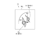
このワークステーション3では、図3に模式的に示す如く、マンモグラフィ装置1によって収集された2次元のマンモグラフィ画像IMmを表示器13(特に、高精細モニタ:以下、表示器と呼ぶ)に表示するときに、そのマンモグラフィ画像IMmに、特定形状の領域Rspをオペレータの希望に従った位置に重畳して表示させることを第1の特徴とする。
In this
さらに、その特定形状Rspの領域を成す複数の画素Pnそれぞれの輝度(即ち、画素値)について、その原輝度(オリジナルの輝度:収集したマンモグラフィ画像そのままの輝度)と、その原輝度の広がりを特徴付ける処理を規定した(又は、予めデフォルトで決定されている)合成パターンから求められた輝度とを合成し、その合成された輝度に従ってマンモグラフィ画像IMmに上記特定形状の領域Rspを重畳表示する、ことを更なる第2の特徴とする。 Further, for the brightness (that is, pixel value) of each of the plurality of pixels Pn forming the region of the specific shape R sp , the original brightness (original brightness: the brightness of the collected mammography image as it is) and the spread of the original brightness are displayed. The brightness obtained from the composite pattern that defines the characterizing process (or is determined in advance by default) is combined, and the region R sp of the specific shape is superimposed and displayed on the mammography image IM m according to the combined brightness. This is a second feature.
この表示により、マンモグラフィ画像IMm上に、特別に加工処理した特定形状の領域Rspが重畳表示されることになる。この特定形状の領域Rspは、オペレータの入力器12を経由した指示に応じて表示器13の画面上で自在に移動可能になっている。マンモグラフィ画像IMmは画面上で固定表示されるので、特定形状の領域Rspのみをその移動指示に沿って移動させ、その移動先の画素の基に合成輝度が演算されて、表示器13の表示同期に沿って更新・表示させることができる。
By this display, the specially processed region R sp of a specific shape is superimposed and displayed on the mammography image IM m. The region R sp having a specific shape can be freely moved on the screen of the
<本実施形態の特徴>
ここで、本実施形態に係るワークステーション3で実施される読影作業に有用な特徴を説明する。
<Characteristics of this embodiment>
Here, features useful for the image interpretation work performed on the
<第1の特徴について>
この特定形状の領域Rspの形状は、例えば円形として設定されるが、円形でなくてもよく、他の様々な形状を採ることができる。例えば、この領域Rspは5角形、6角形などの多角形であってもよいし、楕円形であってもよい。この形状の変形例については、後述する。
<About the first feature>
The shape of the region R sp of this specific shape is set as, for example, a circle, but it does not have to be a circle, and various other shapes can be adopted. For example, this region R sp may be a polygon such as a pentagon or a hexagon, or may be an ellipse. A modified example of this shape will be described later.
オペレータは、この領域Rspをマンモグラフィ画像上の病変が疑われる部位に当てて、その部位に病変が隠れることができるかどうかを判断するために使用できる。マンモグラフィ画像上で、例えば、乳腺の構造物の一部の表示輝度が高いため、目視では腫瘤のように見える部分がある場合、その部分に特定形状の領域Rspを当てる。これは、その局所的な領域Rspが病変を隠すことができる大きさか否かを確認するためである。つまり、この領域Rspを当てることは、かかる疑わしい部分の大きさを確認するための物差しによる判定であるので、以下、特定形状の領域Rspをその機能面から「模擬領域Rsp」と呼ぶことにする。なお、この「模擬領域Rsp」は、読影医からみれば、関心領域(ROI)であるとも言える。 The operator can apply this region R sp to a suspected lesion on the mammography image to determine if the lesion can be hidden at that site. On the mammography image, for example, when there is a part that looks like a tumor visually because the display brightness of a part of the mammary gland structure is high, a region R sp of a specific shape is applied to that part. This is to confirm whether the local region R sp is large enough to hide the lesion. That is, since applying this region R sp is a judgment by a ruler for confirming the size of the suspicious portion, the region R sp having a specific shape is hereinafter referred to as a "simulated region R sp" from the functional aspect. I will decide. It should be noted that this "simulated area R sp " can be said to be an area of interest (ROI) from the perspective of an image interpreter.
この「模擬領域Rsp」の使用の一例として、マンモグラフィ画像IMmの画面上で「模擬領域Rsp」を当てる場合、その初期位置から又はいま判定した部分から、オペレータの入力器12を介した指示に応じて、次の見たい(疑わしい)部分へ「模擬領域Rsp」を移動させることになる。
As an example of the use of this "simulated area R sp ", when the "simulated area R sp " is applied on the screen of the mammography image IM m , the operator's
この模擬領域Rspは、第1義的には、上述のように物差し機能を持つため、その模擬領域Rspのサイズは極めて重要である。このサイズは、読影において発見しようとする病変(例えば腫瘤)の、「これ以上大きいものを見逃してはいけない」という最小値に設定されることが望ましい。更に言えば、模擬領域Rspのサイズは、発見が要求される病変の最小サイズでもある。 Since this simulated region R sp primarily has a ruler function as described above, the size of the simulated region R sp is extremely important. It is desirable that this size be set to the minimum value of "don't miss a larger one" of the lesion (eg, mass) to be found in the interpretation. Furthermore, the size of the simulated region R sp is also the minimum size of the lesion required to be detected.
このため、一例として、模擬領域Rspは直径1cmの円形領域として設定される。この例の場合、乳腺構造内に径1cmの腫瘤病変が隠れることができるか否かを目視で判定でき、読影をサポートできる。 Therefore, as an example, the simulated region R sp is set as a circular region having a diameter of 1 cm. In the case of this example, it is possible to visually determine whether or not a tumor lesion having a diameter of 1 cm can be hidden in the mammary gland structure, and it is possible to support interpretation.
これを模式的に表すと、図4(A)の場合、乳腺構造NSの一部分は模擬領域Rspよりも小さいので、この部分には1cm以上の径の腫瘤病変は隠れることができないと判定できる。反対に、同図(B)に示すように、模擬領域Rspを当てた乳腺構造NSの別の一部分は、その領域Rspよりも大きいので、そこの部分には腫瘤病変が輝度的に隠れて存在している又は存在する可能性があると判定できる。このため、オペレータは同図(A)から同図(B)へと模擬領域Rspを移動させ、各移動先の位置において腫瘤病変が無いか否か、またそこで乳腺構造NSに隠れてしまっていないか等に注意を払いながら、読影を行うことができる。 Representing this schematically, in the case of FIG. 4A, since a part of the mammary gland structure NS is smaller than the simulated area R sp, it can be determined that a tumor lesion having a diameter of 1 cm or more cannot be hidden in this part. .. On the contrary, as shown in FIG. 3B, another part of the mammary gland structure NS to which the simulated area R sp is applied is larger than the area R sp , so that the tumor lesion is brightly hidden in that part. It can be determined that it exists or may exist. For this reason, the operator moves the simulated area R sp from the figure (A) to the figure (B), and whether or not there is a tumor lesion at each destination position, and where it is hidden by the mammary gland structure NS. You can read the image while paying attention to whether or not it is present.
<第2の特徴について>
マンモグラフィ画像IMmの画面上で「模擬領域Rsp」を関心がある局所部分に当てて(設定して)、後述する合成処理を指示した場合、輝度合成パターンによって、その局所部分の輝度の合成処理がなされる。これにより、上述した物差し機能に加え、模擬領域Rspを成す画素の原輝度(マンモグラフィ画像のオリジナルの画素値)をその特性に応じた合成輝度に置換することができる。このため、原輝度の特性に応じた模擬領域Rspがマンモグラフィ画像IMmに重畳した状態で表示器13に表示される。この表示も、表示器13の画面表示に同期して更新される。
<About the second feature>
When the "simulated area R sp " is applied (set) to the local part of interest on the screen of the mammography image IM m and the compositing process described later is instructed, the brightness of the local part is synthesized by the brightness compositing pattern. Processing is done. Thereby, in addition to the above-mentioned ruler function, the original luminance (original pixel value of the mammography image) of the pixels forming the simulated region R sp can be replaced with the composite luminance according to the characteristics. Therefore, the simulated region R sp corresponding to the characteristics of the original luminance is displayed on the
上記合成処理は、オペレータが選択可能な又はデフォルト設定で決められている1つ又は複数の合成パターン(輝度合成モード)に従ってなされる。この合成処理は、模擬領域Rspを成す画素の原輝度が呈する特性に基づいて、当該模擬領域Rspに相当する病変部が乳腺組織に隠れていないか否かを視覚的に明示しようとする処理である。このため、隠れ判定の対象である病変部は模擬領域Rspに相当するので、この模擬領域Rspを満月に例えると、乳腺組織は満月に映る雲であると想定できる。このため、満月を雲が覆ってしまうと、雲の裏側にある満月は見えないことになる、この隠れ状態を目視的に明示するために、本実施形態では4種類の合成パターン(輝度合成モード)に基づく処理が選択可能に用意されている。 The compositing process is performed according to one or more compositing patterns (luminance compositing mode) that can be selected by the operator or determined by default settings. The synthesis process is based on the properties exhibited by the original brightness of the pixels constituting the simulated region R sp, lesion corresponding to the simulated region R sp is to visually demonstrate whether or not hidden mammary tissue It is a process. Therefore, since the lesion is hidden determination of the target corresponding to the simulated region R sp, likened the simulated area R sp full moon, mammary tissue can be assumed that a cloud reflected in the full moon. Therefore, if the cloud covers the full moon, the full moon behind the cloud cannot be seen. In order to visually clarify this hidden state, four types of composite patterns (brightness composite mode) are used in the present embodiment. ) Is available for selection.
<4種類の合成パターン>
・第1の合成パターン
第1の合成パターンは、模擬領域Rspの辺縁画素のみ輝度を合成し、内部はマンモグラフィ画像自体の画素値、即ち、オリジナルの画素値で出力する。この第1の合成パターンは、模擬領域Rspの内部のオリジナルの画素値を正確にチェックしたい場合に有効である。
<4 types of synthetic patterns>
-First composite pattern In the first composite pattern, the brightness is synthesized only at the marginal pixels of the simulated area R sp , and the inside is output with the pixel value of the mammography image itself, that is, the original pixel value. This first composite pattern is effective when it is desired to accurately check the original pixel value inside the simulated region R sp.
辺縁画素の出力輝度を合成する場合、一定の輝度で出力してもよいし、周囲の表示輝度に埋もれないように、オリジナルの輝度と中間輝度とをXORした値を出力値としてもよい。 When synthesizing the output brightness of the peripheral pixels, the output may be output at a constant brightness, or the value obtained by XORing the original brightness and the intermediate brightness may be used as the output value so as not to be buried in the surrounding display brightness.
図5に、この第1の合成パターンによる模擬領域Rspの一例を示す。同図に示すように、模擬領域Rspの辺縁を示す線Lspのみが描出されている。 FIG. 5 shows an example of the simulated region R sp based on this first synthetic pattern. As shown in the figure, only the line L sp indicating the edge of the simulated region R sp is drawn.
この第1の合成パターンによる合成処理であっても、マンモグラフィ画像IMmにおいて、腫瘤部位に模擬的に相当させた模擬領域Rspが乳腺領域に隠れてしまわないか否かを判断する乳腺構造の読影に有効である。 Even in the synthetic process using this first synthetic pattern, in the mammography image IM m , it is determined whether or not the simulated region R sp simulated to correspond to the tumor site is hidden in the mammary gland region. Effective for interpretation.
・第2の合成パターン
第2の合成パターンは、模擬領域Rspの領域内の画素について、オリジナルの輝度をアルファ値として用いて、オリジナル輝度と特定値をアルファブレンドして出力する。これにより、輝度に対応した透け感で領域内を表現できる。
-Second composite pattern The second composite pattern uses the original brightness as an alpha value for the pixels in the region of the simulated area R sp , and outputs the original brightness and the specific value by alpha blending. As a result, the inside of the region can be expressed with a sense of sheerness corresponding to the brightness.
この第2の合成パターンを使用する場合、その合成式は下記1,2の2通りで提供できる。 When this second synthetic pattern is used, the synthetic formula can be provided in the following two ways, 1 and 2.
合成式(1):out=r*org+(1-r)*a
合成式(2):our=r*org+(1-r)*a*δi,j
ここで、
Org:画素の原輝度、
r=org/階調幅、
a:定数(例えばa=128)
δi,j:模擬領域Rspの位置(i,j)に依存した、球体のグラデーションを模擬した係数である。これにより、合成式(1)に基づいて、例えば図6(A)に示すように、マンモグラフィ画像IMmに模擬領域Rspが重畳表示され、合成式(2)に基づいて、例えば図6(B)に示すように、マンモグラフィ画像IMmに模擬領域Rspが重畳表示される。
Synthesis formula (1): out = r * org + (1-r) * a
Synthesis formula (2): our = r * org + (1-r) * a * δ i, j
here,
Org: Pixel original brightness,
r = org / gradation width,
a: Constant (eg a = 128)
δ i, j : A coefficient that simulates the gradation of a sphere, depending on the position (i, j) of the simulated region R sp. As a result, based on the composite formula (1), for example, as shown in FIG. 6 (A), the simulated region R sp is superimposed and displayed on the mammography image IM m , and based on the composite formula (2), for example, FIG. 6 ( As shown in B), the simulated region R sp is superimposed and displayed on the mammography image IM m.
・第3の合成パターン
模擬領域Rspを構成する各画素について、その原輝度が閾値未満であるか閾値以上であるかに応じて、2通りの合成式を切り換えて合成輝度を演算する。閾値は、画素の原輝度が256階調で表されるときに、例えば108に設定される。この閾値は変更可能である。
-Third synthesis pattern For each pixel constituting the simulated region R sp , the composite brightness is calculated by switching between two synthesis formulas depending on whether the original brightness is less than or equal to the threshold value. The threshold is set to, for example, 108 when the original luminance of the pixel is represented by 256 gradations. This threshold can be changed.
一例として、各画素の原輝度が閾値未満である場合、
合成式(3):out=(1-ru)*org+ru*192+128
ru=org/255
を使用し、各画素の原輝度が閾値以上である場合、

Synthesis formula (3): out = (1-r u ) * org + r u * 192 + 128
r u = org / 255
If the original brightness of each pixel is greater than or equal to the threshold
この第3の合成パターンで用いられる閾値の設定は、合成輝度の表示結果に与える影響は大きい。本機能は乳腺構造に腫瘤病変が隠れることができるかどうかの判定をサポートすることが主目的であるので、その閾値は乳腺組織と脂肪組織を分離する値が初期値として指定されるようになっている。勿論、この閾値はオペレータが事前に又は読影途中で変更可能になっている。 The setting of the threshold value used in this third composite pattern has a great influence on the display result of the composite brightness. Since the main purpose of this function is to support the determination of whether a mass lesion can be hidden in the mammary gland structure, the threshold value for separating the mammary gland tissue and the adipose tissue is specified as the initial value. ing. Of course, this threshold can be changed by the operator in advance or during interpretation.
このため、本実施形態では、この第3の合成パターンに用いる閾値初期値は、乳房領域内のヒストグラムに基づく2値化判別手法である大津の手法(Otsu method)を用いて自動的に決定されるように構成されている。この手法で決定された閾値は、概ね乳腺組織と脂肪組織を分離する値に設定される。勿論、そのように自動設定された閾値は、オペレータの操作(マウスホイール操作など)により変更可能に構成されている。 Therefore, in the present embodiment, the initial threshold value used for this third synthetic pattern is automatically determined by using the Otsu method, which is a binarization discrimination method based on the histogram in the breast region. It is configured to. The threshold determined by this method is generally set to a value that separates mammary gland tissue and adipose tissue. Of course, such an automatically set threshold value is configured to be changeable by an operator's operation (mouse wheel operation, etc.).
図7に、自動設定された閾値に基づく模擬領域Rspを重畳表示させたマンモグラフィ画像IMm(同図(A))から、その閾値を小さくした場合の同様のマンモグラフィ画像IMm(同図(B))と、その閾値を大きくした場合の同様のマンモグラフィ画像IMm(同図(C))とを対して例示している。閾値を大きくすることで、合成式(3)で演算される画素がより増えるので、閾値未満の輝度を持つ原画素の表示輝度がより高くなり、その視覚的効果が強まる(同図(C))。 FIG. 7 shows a similar mammography image IM m when the threshold value is reduced from the mammography image IM m (Fig. (A)) in which the simulated region R sp based on the automatically set threshold value is superimposed and displayed (Fig. 7 (Fig. 7)). B)) and a similar mammography image IM m (FIG. 3C) when the threshold value is increased are illustrated. By increasing the threshold value, the number of pixels calculated by the composite formula (3) increases, so that the display brightness of the original pixel having a brightness lower than the threshold value becomes higher and the visual effect is strengthened (Fig. (C)). ).
なお、図8(A),(B)には、合成式(3)及び(4)に基づく入力輝度(原輝度:原輝度=108=閾値)に対する出力輝度(合成輝度)及び擬似病変(擬似領域)の画素の輝度それぞれの特性例を示す。 In addition, in FIGS. 8A and 8B, the output luminance (synthetic luminance) and the pseudo lesion (pseudo-lesion) with respect to the input luminance (original luminance: original luminance = 108 = threshold value) based on the synthetic formulas (3) and (4) are shown. An example of the characteristics of each of the brightness of the pixels in the area) is shown.
これにより、例えば図7に示すように、マンモグラフィ画像IMmに模擬領域Rspが重畳表示され、雲間から顔を出して見える満月の一部(腫瘤部分を模擬した一部)は、所定の閾値未満の輝度を有するため、その閾値未満であることが明確に描出されように高い輝度値で表示される。これに対し、雲(乳腺組織)が覆う満月の残り部分は、閾値以上の輝度を有する画素である。このため、上記合成式(4)に基づいて、シグモイド関数を用いられ、高輝度になるほど出力値が収束するような疑似病変の項が、原輝度に足し合わせられる。これにより乳腺構造(雲)の裏側に病変(模擬領域Rsp)が存在するように合成輝度が演算され、表示される。 As a result, for example, as shown in FIG. 7, the simulated region R sp is superimposed and displayed on the mammography image IM m, and the part of the full moon (the part simulating the mass part) that appears to appear from between the clouds has a predetermined threshold value. Since it has a brightness of less than that, it is displayed at a high brightness value so that it is clearly defined that it is below the threshold value. On the other hand, the rest of the full moon covered by the cloud (mammary gland tissue) is a pixel having a brightness equal to or higher than the threshold value. Therefore, based on the above synthetic formula (4), the sigmoid function is used, and the term of the pseudo-lesion in which the output value converges as the brightness increases is added to the original brightness. As a result, the synthetic brightness is calculated and displayed so that the lesion (simulated area R sp ) exists on the back side of the mammary gland structure (cloud).
この結果、満月が雲の後ろに隠れるような透け感を描出させることができ、乳腺構造の濃淡を奥行き感のある見え方に変換する視覚的効果を発揮できる。 As a result, it is possible to create a sense of sheerness in which the full moon is hidden behind the clouds, and it is possible to exert a visual effect of converting the shading of the mammary gland structure into a deep appearance.
・第4の合成パターン
第4の合成パターンでは、模擬領域Rspの各画素の原輝度から当該画素の平均線吸収係数を推定し、擬似病変を模擬したモデル(模擬領域)を埋め込んだ場合の合成線吸収係数を算出して、それらの輝度を合成し出力する。
-Fourth synthetic pattern In the fourth synthetic pattern, the average line absorption coefficient of each pixel in the simulated area R sp is estimated from the original brightness of each pixel, and a model (simulated area) simulating a simulated lesion is embedded. The combined line absorption coefficient is calculated, and their brightness is combined and output.
具体的には、模擬領域Rspを成す各画素における原輝度から推定した平均線吸収係数と腫瘤の線吸収係数を合成した値を演算し、その値をパラメータとして合成輝度を演算する。 Specifically, a value obtained by combining the average line absorption coefficient estimated from the original brightness of each pixel forming the simulated region R sp and the line absorption coefficient of the tumor is calculated, and the combined brightness is calculated using that value as a parameter.
図9(A),(B),及び(C)は擬似病変のモデルを埋め込み且つ脂肪/乳腺の割合を変えたファントムのマンモグラフィ画像の例を示す。同図(A),(B),(C)に示すように、脂肪組織(脂肪100%)から、平均的な乳房組織(脂肪50%、乳腺50%)、及び、dense breastな乳房組織(一例として脂肪30%、乳腺70%)へと、乳腺の割合が多くなるにつれて、擬似病変の合成成分が小さくなり、乳腺領域により溶け込んで表示される。 9 (A), (B), and (C) show an example of a mammography image of a phantom in which a model of a pseudo-lesion is implanted and the fat / mammary gland ratio is changed. As shown in FIGS. (A), (B), and (C), from adipose tissue (100% fat) to average breast tissue (50% fat, 50% mammary gland) and dense breast tissue (100% fat). As an example, as the proportion of the mammary gland increases to 30% fat and 70% mammary gland), the synthetic component of the pseudo-lesion becomes smaller and is displayed as being more integrated into the mammary gland region.
このため、疑似病変を埋め込んで合成した線吸収係数を逆変換して出力輝度として用い、疑似病変の出力を求める。逆変換はある特定の表示輝度と線吸収係数の組み合わせから近似された指数関数となる。このため、撮影装置の違いや画像処理の違いによる画質のばらつきに適切に対応する必要がある。 Therefore, the line absorption coefficient synthesized by embedding the pseudo-lesion is inversely transformed and used as the output brightness to obtain the output of the pseudo-lesion. The inverse transformation is an exponential function approximated by a combination of a particular display luminance and the line absorption coefficient. Therefore, it is necessary to appropriately cope with the variation in image quality due to the difference in the photographing device and the difference in the image processing.
撮影装置の違いや画像処理の違いによる画質のばらつきに対応するため、合成された線吸収係数をパラメータとして疑似病変の合成成分を算出してオリジナルの表示輝度に加算し、出力輝度を合成する。 In order to deal with variations in image quality due to differences in imaging equipment and image processing, the composite component of the pseudo-lesion is calculated using the combined line absorption coefficient as a parameter and added to the original display brightness to synthesize the output brightness.
合成された線吸収係数を0〜1.0の正規化されたパラメータに変換して、疑似病変の合成成分の算出式に適用し、出力輝度を算出する。 The synthesized line absorption coefficient is converted into a normalized parameter of 0 to 1.0 and applied to the calculation formula of the synthetic component of the pseudo-lesion to calculate the output brightness.
乳房厚みよる疑似病変の合成成分への影響は、指数関数のオフセット量を調整して軽減する。また、疑似病変の球体陰影を模擬するには、合成された線吸収係数は厚み均一の円柱形状で算出し、合成成分の表示補正量に球体形状のパラメータを適用して実現する。 The effect of breast thickness on the synthetic components of pseudolesions is mitigated by adjusting the amount of exponential offset. Further, in order to simulate the spherical shadow of the pseudo lesion, the synthesized line absorption coefficient is calculated by a cylindrical shape having a uniform thickness, and the parameter of the spherical shape is applied to the display correction amount of the synthetic component.
なお、本実施形態に係るワークステーション3では、上記第4の合成パターンを省略して実施し、前述した第1〜第3の合成パターンのみを採用し、この第1〜第3の合成パターンを適宜、選択又は切替え可能に構成してもよい。
In the
次に、図10を参照して、ワークステーション3で実行される読影処理の一例を説明する。この読影処理は演算装置11のCPU21によって実行される。
Next, an example of the image interpretation process executed on the
CPU21は、ステップS10において、オペレータとの間でインターラクティブに、インターフェース26を介して画像サーバ2に患者情報や検査情報を画像送信要求と共に送る。これに応えて、画像サーバ2から、対応するマンモグラフィ画像が送信されてくるので、この画像データを例えば専用の画像記憶装置24に保存する。
In step S10, the
次いで、CPU21は、ステップS11にて、受信したマンモグラフィ画像の表示モードをオペレータとの間でインターラクティブに決定する。この表示モードとしては、1つのマンモグラフィ画像(左右の乳房の何れかの単独表示、または、左右の乳房を並置表示(この並置表示の場合、左右のペア画像を同方向にて並置する表示モード、左右対称に並置する表示モードを選択)などがある。
Next, in step S11, the
次いで、CPU21は、ステップS12にて、決定された表示モードでマンモグラフィ画像を表示器13に表示させる。いま、左右何れかの乳房のマンモグラフィ画像が単独で表示器13の画面に表示されているものとする。
Next, in step S12, the
この表示が済むと、CPU21は、表示器13の表示画面を見ているオペレータ(医師など)の指令によって、又は、画像認識演算に基づく自動設定によって、前述した模擬領域Rspの初期位置を決定する(ステップS13)。
After this display is completed, the
さらに、CPU21は、その模擬領域Rspの形状及び/又はサイズを、オペレータからの指令に応じてインターラクティブに決定する(ステップS14)。このため、このステップS14は、機能的に領域変更手段を担う。
Further, the
例えば、模擬領域Rspとしては、乳腺組織に隠れてしまい、目視で発見できないという状況を回避せんがために、画面上での乳腺組織の幅、大きさや、見逃すことなく読影したい腫瘤などの病変部の形状及び/又はサイズを考慮して選択・設定可能に構成されている。それら形状及び/又はサイズは、一例としては、予めテーブル(例えば第1の記憶装置22)に保存されているので、オペレータはそれを参照して選択すればよい。勿論、オペレータがその場で任意のサイズを指定するようにしてもよい。
例えば、形状としては、模擬領域Rspに持たせる物差し機能を第1に考えると、図13に示すように、形(round)の模擬領域Rsp-1が適当である(図13(A)参照)。これに、病変部の形状まで追加的に考慮する読影を考えると、楕円形(oval)の模擬領域Rsp-2(図13(B)参照)、多角形(polygonal)の模擬領域Rsp-3(図13(C)参照)、分葉形(lobular)の模擬領域Rsp-4(図13(D)参照)、不整形(irregular)の模擬領域Rsp-5(図13(E)参照)のうちの1つ又は複数の形状を選択可能に設定しておいてもよい。これらの模擬領域は、「マンモグラフィガイドライン、第3判増補版、編集(社)日本医学放射線学会/(社)日本放射線技術学会、発行 医学書院」、「第6章 マンモグラム所見用語、40頁、図6−1 腫瘤の形状のシェーマ」に基づく基本的な形状領域である。実際には、この基本形状が崩れて変形し、さらには、周辺からspiculaが飛び出ているものもある。
本発明では、これらの多様な形状の模擬領域Rsp(Rsp-1、Rsp-2、Rsp-3、Rsp-4、Rsp-5)であっても、その例えば一番長い径を既知のサイズとして(円形の場合には直径R1)保有しておけばよく(図13中の径R2、R3、R4、R5を参照)、これにより物差し機能も得られる。
このため、これらの模擬領域Rspはその形状毎に及び/又はサイズ(径)毎に、例えば予め第1の記憶装置22に、その形状及び/サイズを示すデータとして保存されている。この場合、サイズ(径)については、読影者が読影時に任意の値をインターラクティブに設定できるようにしてもよい。
勿論、円形の模擬領域Rsp-1だけを設定可能に保持し、そのサイズ(直径)のみを一定範囲(例えば5mm〜15mm)で連続的に又は段階的に変更可能に設定してもよい。
For example, in order to avoid the situation where the simulated area R sp is hidden by the mammary gland tissue and cannot be visually detected, the width and size of the mammary gland tissue on the screen and lesions such as a mass that should be read without being overlooked. It is configured to be selectable and set in consideration of the shape and / or size of the part. As an example, these shapes and / or sizes are stored in a table (for example, the first storage device 22) in advance, so that the operator may refer to and select them. Of course, the operator may specify an arbitrary size on the spot.
For example, as a shape, the ruler function to be provided in the simulated region R sp is considered first, and as shown in FIG. 13, the simulated region R sp-1 of the shape (round) is suitable (FIG. 13 (A)). reference). Considering the interpretation that additionally considers the shape of the lesion, the elliptical (oval) simulated area R sp-2 (see Fig. 13 (B)) and the polygonal (polygonal) simulated area R sp- 3 (see Fig. 13 (C)), polygonal simulated area R sp-4 (see Fig. 13 (D)), irregular simulated area R sp-5 (see Fig. 13 (E)). One or more of the shapes (see) may be set to be selectable. These simulated areas are described in "Mammography Guidelines, 3rd Size Augmentation, Editing (Japanese Society of Radiological Technology) / Japanese Society of Radiological Technology, Igaku-Shoin", "Chapter 6 Mammogram Finding Terms, page 40, Figure". It is a basic shape area based on "6-1 Shamer of mass shape". In reality, this basic shape collapses and deforms, and in some cases, spicula protrudes from the periphery.
In the present invention, even these variously shaped simulated regions R sp (R sp-1 , R sp-2 , R sp-3 , R sp-4 , R sp-5 ) are, for example, the longest. It suffices to keep the diameter as a known size (diameter R1 in the case of a circle) (see diameters R2, R3, R4, R5 in FIG. 13), whereby a ruler function can also be obtained.
Therefore, these simulated regions R sp are stored in advance in the
Of course, only the circular simulated region R sp-1 may be held in a settable manner, and only the size (diameter) thereof may be set to be continuously or stepwise changeable within a certain range (for example, 5 mm to 15 mm).
例えば、そのような形状及びサイズとして、実際の乳房内での物理的な(実空間で)ディメンジョンとして直径1cmの円形の模擬領域Rspが設定される。勿論、形状やサイズは、これ以外のものであってもよい。サイズを小さく、即ち、より小さい病変を読影しようとして、例えば直径8mm、5mmの円形、多角形を設定してよい。模擬領域Rspを実空間で小さく設定するほど、それによって模擬される病変のサイズも小さいことを意味しているので、どの位の形状及びサイズを選択するかについては、読影作業量などとのバランスを考慮してオペレータにより決められる。 For example, as such a shape and size, a circular simulated region R sp with a diameter of 1 cm is set as a physical (in real space) dimension within the actual breast. Of course, the shape and size may be other than this. For example, a circular or polygon with a diameter of 8 mm or 5 mm may be set in an attempt to interpret a lesion having a small size, that is, a smaller lesion. The smaller the simulated area R sp is set in the real space, the smaller the size of the lesion simulated by it. It is decided by the operator in consideration of the balance.
次いで、CPU21は、上記模擬領域Rspをマンモグラフィ画像IMmに重畳表示させるときに必要な、マンモグラフィ画像IMmとの画素の輝度(画素値)の合成に使用する合成パターンを選択する(ステップS15)。例えば、この合成パターンとしては前述した第1〜第3の3種類の合成パターンが用意されているので、オペレータはこれをインターラクティブに選択することで、何れかの合成パターンを指定することができる。
Then,
なお、上述した各種の準備ステップは必ずしも例示した順番に限定されず、別の順番で行ってもよいし、所望の順番や決定内容を予めデフォルトで設定しておいてもよい。 The various preparation steps described above are not necessarily limited to the order illustrated, and may be performed in a different order, or a desired order and determination contents may be set in advance by default.
このように準備が整うと、CPU21は模擬領域Rspを指定しながら移動させて読影を行うか否かのコマンドを待つ(ステップS16)。オペレータが読影開始を指令すると(ステップS16,YES)、CPU21は最初に、模擬領域Rspがマンモグラフィ画像IMmの初期位置に置き、その初期位置において模擬領域Rspを構成しているマンモグラフィ画像IMmの複数の画素Pnを決定する(ステップS17)。この複数の画素Pnは、図3に示したように、縦横のx、y座標上の位置(i,j)によって特定される。
When the preparation is completed in this way, the
これが済むと、CPU21は、その複数の画素Pnのうちの最初の対象となる画素を座標値で指定する(ステップS18)。次いで、CPU21は、選択した第1〜第3の合成パターンの何れかによる処理法にしたがって、その対象画素における輝度の合成処理を行い、その処理結果を一時的に例えば第2の記憶装置23に保管する(ステップS19)。それぞれの合成パターンにより処理法は、前述した通りである。
When this is completed, the
この後、CPU21は、輝度合成すべき対象画素が未だ残っているか否かを判断し(ステップS20)、未だ残っていると判断したときには(ステップS20,YES)、その処理をステップS18に進めて上述したステップS19,S20の処理を繰り返す。これは、模擬領域Rspを構成している全ての対象画素の処理が済むまで繰り返される。
After that, the
このため、ステップS20でNOの判断になるときは、模擬領域Rspを構成する対象画素全ての処理が終わったことなる。このため、CPU21は、表示用のフレームデータを更新して表示データを作成する(ステップS21)。この表示データは、CPU21により、インターフェース26を介して表示器13に送られ、画面表示される(ステップS22)。
Therefore, when the determination of NO is made in step S20, it means that the processing of all the target pixels constituting the simulated area R sp has been completed. Therefore, the
これにより、表示器13にはそれまでの準備作業の画面に代えて又はその一部として、マンモグラフィ画像IMmの初期位置に模擬領域Rspが重畳して表示される(ステップS22)例えば、図5,6,7を参照)。 As a result, the simulated area R sp is superimposed and displayed on the display 13 at the initial position of the mammography image IM m in place of or as a part of the screen of the preparatory work up to that point (step S22), for example, FIG. See 5, 6 and 7).
この重畳された模擬領域Rspの各輝度(各画素)は、前述した第1〜第3の合成パターンによって原輝度を、各合成パターンの処理法によって、すくなとも一部の画素は合成処理(変調)されたものであり、単に、領域全体を別の輝度の画素で置換したり上書きしたりしたものではない。つまり、模擬領域Rspは、原画素の輝度情報を少なくとも一部を持ちながら、腫瘤等の病変を模擬した領域情報を持ち合わせている。 Each brightness (each pixel) of the superimposed simulated region R sp is the original brightness by the above-mentioned first to third composite patterns, and at least a part of the pixels are composited by the processing method of each composite pattern. It is modulated) and does not simply replace or overwrite the entire area with pixels of different brightness. That is, the simulated region R sp has region information simulating a lesion such as a tumor while having at least a part of the luminance information of the original pixel.
CPU21は更に、オペレータがマンモグラフィ画像IMm上で模擬領域Rspを移動させたか否かを判断する(ステップS23)。さらに、この判断結果がNOとなるときには、終了指示があるまで模擬領域Rspの移動を判断しながら待機し、終了指示があれば、読影を終了する(ステップS24)。これに対し、ステップS23でYESの判断になるときには、その処理をステップS17まで戻し、更新された模擬領域位置における画素決定から合成処理、表示までを行う(ステップS17〜S22)。これにより、例えば図4における(A)の模擬領域Rspの状態から、同(B)の模擬領域Rspの状態に移動して上述した処理が行われる。この一連の処理は、オペレータが模擬領域Rspの移動を止め且つ読影終了の指令を出すまで繰り返される。
The
なお、読影の途中の任意のタイミングにおいて表示モード、模擬領域の形状及びサイズ、使用する合成パターン(つまり、輝度合成モード)等を任意に切り替えることができるようにCPU21で実行する処理手順を組むこと勿論できる。
It should be noted that a processing procedure to be executed by the
ここで、機能的には、ステップS14が領域設定部11Aに相当し、ステップS17が画素特定部11Bに相当し、ステップS18〜S20が輝度合成部11Cに相当し、ステップS21が表示制御部11Dに相当し、ステップS23が移動制御部11Eに相当し、さらに、ステップS11が連動制御部11Fの一部を担う。
Here, functionally, step S14 corresponds to the
また、機能的に、ステップS22が画像表示手段に相当し、ステップS15が選択手段を構成し、さらに、ステップS23が領域移動手段を構成している。 Functionally, step S22 corresponds to the image display means, step S15 constitutes the selection means, and step S23 constitutes the area moving means.
以上のように、本実施形態に係るワークステーション3によれば、オペレータ(医師等)は、用意された複数の合成パターンの中から所望の合成パターンを決定できる。このため、その合成パターンで定めている処理法に基づいて模擬領域Rspの少なくとも一部の画素の輝度(画素値)が変調され、その変調された輝度が元の原輝度に合成されて表示用の模擬領域Rspが作成される。この作成された模擬領域Rspは、オペレータが指定した、マンモグラフィ画像IMm上の所望位置において同画像に重畳して表示される。この重畳表示は、オペレータが模擬領域Rspを移動させる度に、この移動に伴う変更された位置にてなされる。
As described above, according to the
図5,6,及び7に例示したシミュレーション画像から判るように、オペレータは表示器13に表示されたマンモグラフィ画像IMmの画面を目視しながら読影することになる。この画面によれば、マンモグラフィ画像IMmの所望の位置に、模擬領域Rspが丸い満月状の領域として表示され、しかも、少なくともその辺縁が描出される。第2及び第3の合成パターンによれば、模擬領域Rspの辺縁のみならず、その内側の領域も輝度値が処理されて表示される。さらに、その模擬領域Rspに該当する、マンモグラフィ画像IMm上の画素が作っていた全部又は部分的な乳腺組織の輝度情報も少なくとも部分的に残している。これにより、腫瘤等の病変を模した模擬領域Rspとそれ以外の例えば乳腺組織とが適宜に重畳して表示される。 As can be seen from the simulation images illustrated in FIGS. 5, 6 and 7, the operator visually interprets the screen of the mammography image IM m displayed on the display 13. According to this screen , the simulated region R sp is displayed as a round full moon-shaped region at a desired position in the mammography image IM m , and at least the edges thereof are drawn. According to the second and third composite patterns, not only the edge of the simulated region R sp but also the region inside the simulated region R sp is processed and displayed with the luminance value. Furthermore, the luminance information of all or part of the mammary gland tissue formed by the pixels on the mammography image IM m corresponding to the simulated region R sp is also left at least partially. As a result, the simulated region R sp that imitates a lesion such as a tumor and other, for example, mammary gland tissue are appropriately superimposed and displayed.
つまり、この模擬領域Rspが病変の形状及びサイズを模しているので、乳腺組織の一部に、この模擬領域Rspが隠れて見えない場合、その乳腺組織の一部には腫瘤等の病変が隠れている可能性がある。つまり、オペレータは、模擬領域Rspを移動させながら関心のある(疑いのある)部位に当てることで、その部分が病変を隠してしまう箇所か否かを迅速に判断できる。つまり、オペレータは、この模擬領域Rsp、即ち病変を輝度的に隠してしまう又は見難くしてしまうような部位を、その直感をも参酌しながら探索する物差し機能を得ることができる。 That is, since this simulated region R sp imitates the shape and size of the lesion, if this simulated region R sp is hidden and invisible in a part of the mammary gland tissue, a tumor or the like is formed in a part of the mammary gland tissue. The lesion may be hidden. That is, the operator can quickly determine whether or not the simulated region R sp is a portion that hides the lesion by hitting the region of interest (suspected) while moving the simulated region R sp. That is, the operator can obtain a ruler function for searching the simulated region R sp , that is, a portion that brightly hides or makes it difficult to see the lesion, taking into consideration its intuition.
したがって、オペレータは模擬領域Rspを関心部位へ移動させながら、その部位の大きさや広がり状態を迅速に判定することができる。勿論、模擬領域Rspが隠れてしまう部位を見つけた場合、別の手法でその部位に病変が有るか否かを確認・診断することになる。このような物差し機能を持つ模擬領域Rspを使わない従来法に比べて、本実施形態の場合、模擬領域Rspのよる補助手段によって読影作業が格段に迅速化し、スループットが上がることを期待できる。加えて、オペレータの読影作業の軽減化も図ることできる。 Therefore, the operator can quickly determine the size and spread state of the simulated region R sp while moving the simulated region R sp to the region of interest. Of course, when a site where the simulated area R sp is hidden is found, it is necessary to confirm and diagnose whether or not there is a lesion in that site by another method. Compared with the conventional method that does not use the simulated area R sp having such a ruler function, in the case of the present embodiment, it can be expected that the image interpretation work will be remarkably speeded up and the throughput will be increased by the auxiliary means by the simulated area R sp. .. In addition, it is possible to reduce the operator's interpretation work.
さらに、この模擬領域Rspを関心部位に移動させることで、オペレータの目視観察時の注意力をその部位に注中させ易いという、言わば、指差し確認的な副次効果も得られる。 Further, by moving the simulated region R sp to the region of interest, it is easy to focus the operator's attention during visual observation on the region, so to speak, a secondary effect of pointing confirmation can be obtained.
[第2の実施形態]
続いて、図11及び図12、並びに、前述した図10を参照して第2の実施形態に係るワークステーションを説明する。この第2の実施形態に置いて、第1の実施形態と同一又は同様の構成要素には同一の符号を用いて、その説明を省略又は簡略化する。
[Second Embodiment]
Subsequently, the workstation according to the second embodiment will be described with reference to FIGS. 11 and 12, and FIG. 10 described above. In this second embodiment, the same reference numerals are used for the same or similar components as those in the first embodiment, and the description thereof will be omitted or simplified.
この第2のワークステーションは、図11に示すように、演算装置11のCPU21が与えられた読影処理のプログラム処理によって、連動制御部11Fを有する。
As shown in FIG. 11, the second workstation has an interlocking
この連動制御を説明すると、疑似病変である模擬領域の位置を、図12(A),(B)に模式的に示すように、同方向のペア画像では同一位置に、左右対のペア画像では左右対称の位置に初期表示させる。この後、オペレータの操作に従って、その初期の位置関係を維持しながら、ペア画像上で連動して更新表示させる。この機能は、図10のステップS13,S16〜S22それぞれにおいて、それらの処理がペア画像それぞれに併行して実施されるころで得られる。このため、ステップS13,S16〜S23は機能的に、図11に示す連動制御部に相当する。 Explaining this interlocking control, as schematically shown in FIGS. 12A and 12B, the positions of the simulated regions that are pseudo-lesions are at the same position in the pair images in the same direction, and in the pair images of the left and right pairs. Initially display at symmetrical positions. After that, according to the operation of the operator, the update display is interlocked on the pair image while maintaining the initial positional relationship. This function is obtained in each of steps S13, S16 to S22 of FIG. 10 when those processes are performed in parallel with each pair of images. Therefore, steps S13 and S16 to S23 functionally correspond to the interlocking control unit shown in FIG.
具体的には、X線マンモグラフィ装置1により左右の乳房を撮影して収集された2つマンモグラフィ画像IMmを表示器13の画面に左右対称に(図12(A)参照)又は同方向に(図12(B)参照)並置して表示される。さらに、表示されている2つのマンモグラフィ画像IMmそれぞれに、模擬領域Rsp(Rsp(L),Rsp(R))が、左右対称の又は前記同方向における同一の位置関係を持つ初期位置に設定される。
Specifically, the two mammography images IM m collected by photographing the left and right breasts with the
さらに、2つのマンモグラフィ画像IMmにおいて、画像間で、輝度合成された2つの模擬領域が互いに、前記左右対称の又は前記同方向における同一の位置関係を保持しながら連動して移動し且つ表示される。 Further, in the two mammography images IM m , the two simulated regions whose brightness is combined move and are displayed in conjunction with each other while maintaining the same positional relationship in the symmetrical or the same direction. NS.
これにより、左右対のマンモグラフィ画像上で模擬領域を左右対称に配置して表示される。このため、前述した第1の実施形態で享受される作用効果に加え、局所的非対称性陰影(FAD)の評価を実施する際に、対側の同領域の表示輝度の比較を模擬領域の位置および大きさを基準にして判断できる。この結果、読影精度をより一層向上させることが期待できる。 As a result, the simulated areas are symmetrically arranged and displayed on the left and right pair of mammography images. Therefore, in addition to the effects enjoyed in the first embodiment described above, when evaluating the local asymmetric shadow (FAD), the position of the simulated region is compared with the display brightness of the same region on the opposite side. And can be judged based on the size. As a result, it can be expected that the interpretation accuracy will be further improved.
なお、前述した実施形態においては、本発明としてマンモグラフィ画像の読影について実施した例を示したが、本発明の要旨を、患者のほかの部位、例えば肺野、胃部を撮影したX線画像を読影する装置及び方法に展開することも可能である。 In the above-described embodiment, an example in which the interpretation of a mammography image is performed is shown as the present invention, but the gist of the present invention is an X-ray image obtained by photographing other parts of the patient, such as the lung field and the stomach. It is also possible to develop into a device and a method for interpreting images.
1 マンモグラフィ装置
3 読影用ワークステーション
11 演算装置
11A 領域設定部
11B 画素特定部
11C 輝度合成部
11D 表示制御部
11E 移動制御部
11F 連動制御部
12 入力器
13 表示器
Rsp(Rsp−1…Rsp−5) 病変を模擬した模擬領域
IMm マンモグラフィ画像
NS 乳腺組織
1
Claims (12)
X線マンモグラフィ装置により撮影された人体の乳房の2次元のX線画像を前記モニタの画面に表示する画像表示手段と、
前記画像表示手段により前記X線画像が表示された前記モニタの前記画面に、予め想定した病変部を検出するために設定した最小サイズ、及び、特定の形状を有する模擬領域を、前記画面に表示される前記乳房の輝度画像に移動可能に設定する模擬領域設定手段と、
前記画面上で前記模擬領域を形成する複数の画素を特定する画素特定手段と、
前記画素特定手段により特定された前記複数の画素の少なくとも一部の複数の原輝度と、当該少なくとも一部の複数の画素に、前記模擬領域の内部に描出される前記乳房の構造物の陰影と当該模擬領域の前記原輝度とに基づいて当該陰影の少なくとも形状、濃淡、又は広がりの状態を目視で判定可能に特徴付ける所定の処理を施した輝度とを合成する輝度合成手段と、
前記輝度合成手段により合成された輝度を有する前記模擬領域を前記モニタに表示されている画面を重畳して表示する重畳表示手段と、
を備えたことを特徴とするマンモグラフィ読影装置。 With a monitor
An image display means for displaying a two-dimensional X-ray image of the human breast taken by an X-ray mammography apparatus on the screen of the monitor, and an image display means.
On the screen of the monitor on which the X-ray image is displayed by the image display means, a minimum size set for detecting a lesion portion assumed in advance and a simulated area having a specific shape are displayed on the screen. A simulated area setting means for setting the brightness image of the breast so as to be movable, and
Pixel specifying means for specifying a plurality of pixels forming the simulated area on the screen, and
The plurality of original luminances of at least a part of the plurality of pixels identified by the pixel identifying means, and the shadow of the breast structure drawn inside the simulated area on the at least a part of the plurality of pixels. and luminance combining means for combining at least a shape, brightness subjected shading, or the determination can characterize certain processing conditions spread visually of the shadow on the basis of said original luminance of the simulated area,
A superimposed display means for displaying the simulated area having the brightness synthesized by the luminance combining means by superimposing the screen displayed on the monitor.
A mammography interpretation device characterized by being equipped with.
前記少なくとも一部の複数の画素の前記原輝度と、当該少なくとも一部の複数の画素の当該原輝度を前記所定の処理で処理した輝度とを画素毎に合成することにより前記輝度の合成を行うように構成されている、
ことを特徴とする請求項1に記載のマンモグラフィ読影装置。 The luminance synthesis means
Wherein the original brightness of a plurality of pixels of said at least part, the synthesis of the by the said at least part of the original brightness of a plurality of pixels and processed in the processing of the plant constant brightness synthesized for each pixel brightness Configured to do,
The mammography image interpretation device according to claim 1.
前記輝度合成手段は、前記複数種の処理法それぞれに応じた複数の輝度合成モードで稼働可能に構成され、
前記読影装置は、
前記複数の輝度合成モードをユーザが任意に選択可能な選択手段と、
前記選択手段により任意の輝度合成モードが選択されたときに、前記ユーザは前記選択された輝度合成モードに応じた前記模擬領域を前記画面上で任意の位置に移動可能な領域移動手段と、を備え、
前記重畳表示手段は、前記領域移動手段により移動される前記模擬領域を前記X線画像と共に前記モニタに更新表示するように構成された、
ことを特徴とする請求項2に記載のマンモグラフィ読影装置。 Said predetermined process includes a plurality of kinds of Disposal Law prepared in advance,
The luminance combining means, operable to be composed of a plurality of the luminance synthesizing mode corresponding to the plurality of kinds of Disposal Law,
The interpretation device is
A selection means that allows the user to arbitrarily select the plurality of luminance synthesis modes, and
When an arbitrary luminance synthesis mode is selected by the selection means, the user can move the simulated region according to the selected luminance synthesis mode to an arbitrary position on the screen. Prepare,
The superimposed display means is configured to update and display the simulated area moved by the area moving means on the monitor together with the X-ray image.
The mammography image interpretation device according to claim 2.
前記模擬領域の辺縁の複数の画素のみの原輝度を、当該模擬領域の辺縁を示す輝度で置換する第1の輝度合成パターンに基づく処理法と、
前記模擬領域の内部の前記各画素の原輝度を、当該原輝度をアルファ値として採用して原輝度と与えられた特定値とをアルファブレンドする第2の輝度合成パターンに基づく処理法と、
前記模擬領域の内部の前記各画素の原輝度を所定の閾値による弁別結果に基づいて前記合成のための処理を切り換える第3の輝度合成パターンに基づく処理法と、
を少なくとも有する、
ことを特徴とする請求項3に記載のマンモグラフィ読影装置。 The plurality of treatment methods are
A processing method based on the first luminance synthesis pattern in which the original luminance of only a plurality of pixels at the edge of the simulated region is replaced with the luminance indicating the edge of the simulated region.
A processing method based on a second luminance synthesis pattern in which the original luminance of each pixel inside the simulated region is alpha-blended with the original luminance by adopting the original luminance as an alpha value, and
A processing method based on a third luminance synthesis pattern that switches the process for the synthesis based on the discrimination result of the original brightness of each pixel inside the simulated region based on a predetermined threshold value, and
Have at least
The mammography image interpretation device according to claim 3.
ことを特徴とする請求項1〜4の何れか一項に記載のマンモグラフィ読影装置。 The simulated area is set to the specific shape and the minimum size set by the operator to prevent oversight of lesions on the X-ray image.
The mammography image interpretation device according to any one of claims 1 to 4.
前記模擬領域を前記画面上で移動させる模擬領域移動手段と、
を備える、
ことを特徴とする請求項1〜5の何れか一項に記載のマンモグラフィ読影装置。 The simulated area setting means includes an initial display setting means that initially displays the simulated area on the screen of the monitor .
A simulated area moving means for moving the simulated area on the screen,
To prepare
The mammography image interpretation device according to any one of claims 1 to 5.
ことを特徴とする請求項1〜6の何れか一項に記載のマンモグラフィ読影装置。 The simulated area setting means includes an area changing means for giving an instruction capable of changing at least one of the minimum size of the simulated area and the specific shape displayed on the screen of the monitor.
The mammography image interpretation device according to any one of claims 1 to 6, wherein the mammography image interpretation device is characterized.
前記模擬領域設定手段は、前記モニタの画面に表示されている前記2つX線画像それぞれに、前記模擬領域を、前記左右対称の又は前記同方向における同一の位置関係を持つ初期位置に設定するように構成され、
前記重畳表示手段は、前記2つX線画像において、前記画像毎に前記輝度合成手段により輝度合成された2つの前記模擬領域を互いに、前記左右対称の又は前記同方向における同一の位置関係を保持しながら連動して表示させるように構成された、
ことを特徴とする請求項1〜7の何れか一項に記載のマンモグラフィ読影装置。 The image display means is configured to display two X-ray images collected by photographing the left and right breasts with the X-ray mammography apparatus symmetrically or juxtaposed in the same direction on the screen of the monitor. ,
The simulated area setting means sets the simulated area in each of the two X-ray images displayed on the screen of the monitor at an initial position having the same positional relationship in the symmetrical or the same direction. Is configured as
In the two X-ray images, the superimposed display means maintains the same positional relationship between the two simulated regions whose brightness is synthesized by the brightness combining means for each image, symmetrically or in the same direction. It was configured to be displayed in conjunction with each other.
The mammography image interpretation device according to any one of claims 1 to 7.
前記X線画像が表示された前記モニタの前記画面に、予め想定した病変部を検出するために設定した最小サイズ、及び、特定の形状を有する模擬領域を、前記画面に表示される前記乳房の輝度画像に移動可能に設定し、
前記模擬領域を形成する複数の画素を特定し、
前記特定された前記複数の画素の少なくとも一部の複数の原輝度と、当該少なくとも一部の複数の画素に、前記模擬領域の内部に描出される前記乳房の構造物の陰影と当該模擬領域の前記原輝度とに基づいて当該陰影の少なくとも形状、濃淡、又は広がりの状態を目視で判定可能に特徴付ける処理を施した輝度とを合成し、
前記合成された輝度を有する前記模擬領域を前記モニタに表示されている画面を重畳して表示する、
ことを特徴とするマンモグラフィ読影方法。 A two-dimensional X-ray image of the human breast taken by an X-ray mammography device is displayed on the monitor screen.
On the screen of the monitor on which the X-ray image is displayed , a simulated area having a minimum size set for detecting a lesion portion assumed in advance and a specific shape is displayed on the screen of the breast. Set to be movable to the brightness image,
A plurality of pixels forming the simulated area are identified, and
The shadow of the breast structure and the shadow of the simulated area drawn inside the simulated area on the at least a part of the plurality of original luminances of the specified plurality of pixels and the plurality of pixels of the simulated area. Based on the original brightness, at least the shape, shading, or spreading state of the shadow is combined with the brightness that has been subjected to a process for visually determining the state.
The simulated area having the combined brightness is displayed by superimposing the screen displayed on the monitor.
A mammography interpretation method characterized by this.
ことを特徴とする請求項9に記載のマンモグラフィ読影方法。 The simulated area is set to the specific shape and the minimum size set by the operator to prevent oversight of lesions on the X-ray image.
The mammography interpretation method according to claim 9.
前記記録媒体に記録された前記プログラムを前記コンピュータが読み出して実行することにより当該コンピュータは:
前記X線マンモグラフィ装置により撮影された人体の乳房の2次元のX線画像を前記モニタの画面に表示する画像表示手段と、
前記画像表示手段により前記X線画像が表示された前記モニタの前記画面に、予め想定した病変部を検出するために設定した最小サイズ、及び、特定の形状を有する模擬領域を、前記画面に表示される前記乳房の輝度画像に移動可能に設定する模擬領域設定手段と、
前記画面上で前記模擬領域を形成する複数の画素を特定する画素特定手段と、
前記画素特定手段により特定された前記複数の画素の少なくとも一部の複数の原輝度と、当該少なくとも一部の複数の画素に、前記模擬領域の内部に描出される前記乳房の構造物の陰影と当該模擬領域の前記原輝度とに基づいて当該陰影の少なくとも形状、濃淡、又は広がりの状態を目視で判定可能に特徴付ける処理を施した輝度とを合成する輝度合成手段と、
前記輝度合成手段により合成された輝度を有する前記模擬領域を前記モニタに表示されている画面を重畳して表示する重畳表示手段と、
を機能的に提供することを特徴とする記録媒体。 A mammography interpretation device equipped with a computer that can display a two-dimensional X-ray image of the human breast taken by an X-ray mammography device on the screen of a monitor and give input information from an input device to the screen display. A recording medium capable of pre-recording a mammography interpretation program that can be read and executed by the computer.
When the computer reads and executes the program recorded on the recording medium, the computer:
An image display means for displaying a two-dimensional X-ray image of a human breast taken by the X-ray mammography apparatus on the screen of the monitor, and an image display means.
On the screen of the monitor on which the X-ray image is displayed by the image display means, a minimum size set for detecting a lesion portion assumed in advance and a simulated area having a specific shape are displayed on the screen. A simulated area setting means for setting the brightness image of the breast so as to be movable, and
Pixel specifying means for specifying a plurality of pixels forming the simulated area on the screen, and
The plurality of original luminances of at least a part of the plurality of pixels identified by the pixel identifying means, and the shadow of the breast structure drawn inside the simulated area on the at least a part of the plurality of pixels. A luminance synthesizing means for synthesizing at least the shape, shading, or spreading state of the shadow based on the original luminance of the simulated region, and the luminance having been subjected to a process for visually determining the state of spreading.
A superimposed display means for displaying the simulated area having the brightness synthesized by the luminance combining means by superimposing the screen displayed on the monitor.
A recording medium characterized by functionally providing.
前記コンピュータが前記記録媒体から前記プログラムを読み出して実行することにより当該コンピュータは:
前記X線マンモグラフィ装置により撮影された人体の乳房の2次元のX線画像をモニタの画面に表示する画像表示手段と、
前記画像表示手段により前記X線画像が表示された前記モニタの前記画面に、
予め想定した病変部を検出するために設定した最小サイズ、及び、特定の形状を有する模擬領域を、前記画面に表示される前記乳房の輝度画像に移動可能に設定する模擬領域設定手段と、
前記画面上で前記模擬領域を形成する複数の画素を特定する画素特定手段と、
前記画素特定手段により特定された前記複数の画素の少なくとも一部の複数の原輝度と、当該少なくとも一部の複数の画素に、前記模擬領域の内部に描出される前記乳房の構造物の陰影と当該模擬領域の前記原輝度とに基づいて当該陰影の少なくとも形状、濃淡、又は広がりの状態を目視で判定可能に特徴付ける処理を施した輝度とを合成する輝度合成手段と、
前記輝度合成手段により合成された輝度を有する前記模擬領域を前記モニタに表示されている画面に重畳して表示する重畳表示手段と、
を機能的に提供することを特徴とするプログラム。
A pre-recording medium that can be read and executed by a computer that can display a two-dimensional X-ray image of the human breast taken by an X-ray mammography device on the screen of a monitor and can give input information to the screen display. In the mammography interpretation program recorded in
When the computer reads the program from the recording medium and executes the program, the computer:
An image display means for displaying a two-dimensional X-ray image of a human breast taken by the X-ray mammography apparatus on a monitor screen, and an image display means.
On the screen of the monitor on which the X-ray image is displayed by the image display means,
A simulated area setting means for setting a minimum size set for detecting a lesion portion assumed in advance and a simulated area having a specific shape so as to be movable on a brightness image of the breast displayed on the screen.
Pixel specifying means for specifying a plurality of pixels forming the simulated area on the screen, and
The plurality of original luminances of at least a part of the plurality of pixels identified by the pixel identifying means, and the shadow of the breast structure drawn inside the simulated area on the at least a part of the plurality of pixels. A luminance synthesizing means for synthesizing at least the shape, shading, or spreading state of the shadow based on the original luminance of the simulated region, and the luminance having been subjected to a process for visually determining the state of spreading.
A superimposed display means that superimposes and displays the simulated area having the brightness synthesized by the luminance combining means on the screen displayed on the monitor.
A program characterized by providing functionally.
Applications Claiming Priority (2)
| Application Number | Priority Date | Filing Date | Title |
|---|---|---|---|
| JP2018076438 | 2018-04-11 | ||
| JP2018076438 | 2018-04-11 |
Publications (3)
| Publication Number | Publication Date |
|---|---|
| JP2019181204A JP2019181204A (en) | 2019-10-24 |
| JP2019181204A5 JP2019181204A5 (en) | 2020-03-26 |
| JP6958790B2 true JP6958790B2 (en) | 2021-11-02 |
Family
ID=68338617
Family Applications (1)
| Application Number | Title | Priority Date | Filing Date |
|---|---|---|---|
| JP2019075004A Active JP6958790B2 (en) | 2018-04-11 | 2019-04-10 | Mammography interpretation device and mammography interpretation method |
Country Status (1)
| Country | Link |
|---|---|
| JP (1) | JP6958790B2 (en) |
Families Citing this family (1)
| Publication number | Priority date | Publication date | Assignee | Title |
|---|---|---|---|---|
| CN111415332B (en) * | 2020-03-05 | 2023-10-24 | 北京深睿博联科技有限责任公司 | Mammary gland X-ray image linkage method and device |
Family Cites Families (5)
| Publication number | Priority date | Publication date | Assignee | Title |
|---|---|---|---|---|
| JP2004222776A (en) * | 2003-01-20 | 2004-08-12 | Fuji Photo Film Co Ltd | Abnormal shadow candidate detector |
| JP4380176B2 (en) * | 2003-02-28 | 2009-12-09 | コニカミノルタホールディングス株式会社 | MEDICAL IMAGE PROCESSING DEVICE AND METHOD FOR DISPLAYING DETECTION RESULT OF ANOTHER SHAPE CANDIDATE |
| JP3930472B2 (en) * | 2003-10-14 | 2007-06-13 | 東芝医用システムエンジニアリング株式会社 | Mammography equipment |
| US20130249903A1 (en) * | 2010-10-13 | 2013-09-26 | Hitachi, Ltd. | Medical image display device, medical information management server |
| JP5885234B2 (en) * | 2011-06-21 | 2016-03-15 | 国立大学法人東京農工大学 | Image analysis method in disease determination apparatus and ultrasonic image forming apparatus |
-
2019
- 2019-04-10 JP JP2019075004A patent/JP6958790B2/en active Active
Also Published As
| Publication number | Publication date |
|---|---|
| JP2019181204A (en) | 2019-10-24 |
Similar Documents
| Publication | Publication Date | Title |
|---|---|---|
| JP2023165034A (en) | System and method for navigating x-ray guided breast biopsy | |
| CN101478917B (en) | Spatially varying 2D image processing based on 3D image data | |
| JP5371949B2 (en) | Medical image display device, medical image photographing device, and medical image display method | |
| US20150287188A1 (en) | Organ-specific image display | |
| JP4786307B2 (en) | Image processing device | |
| KR101405997B1 (en) | Ophthalmic-image processing apparatus and method therefor | |
| DE102004056783A1 (en) | Method and device for segmenting structures in CT angiography | |
| CN102763137A (en) | System and method for generating a 2d image from a tomosynthesis data set | |
| CN104240271B (en) | Medical image-processing apparatus | |
| JP5717377B2 (en) | Image processing apparatus, image processing method, program, and program recording medium | |
| JP2013103023A (en) | Image diagnostic support device and image diagnostic support method | |
| JP4653938B2 (en) | Volume rendering image processing method, volume rendering image processing apparatus, and program | |
| JP6958790B2 (en) | Mammography interpretation device and mammography interpretation method | |
| US9123163B2 (en) | Medical image display apparatus, method and program | |
| JP6564075B2 (en) | Selection of transfer function for displaying medical images | |
| JP6533687B2 (en) | MEDICAL IMAGE PROCESSING APPARATUS, MEDICAL IMAGE PROCESSING METHOD, AND MEDICAL IMAGE PROCESSING PROGRAM | |
| JP2005118510A (en) | Program for measurement and observation of bleeding, tumor, bruise, etc of brain | |
| JP2008119252A (en) | Medical image generating apparatus, method, and program | |
| JP2008086658A (en) | Image display device, and image display program | |
| JP4570383B2 (en) | Medical image display device | |
| JP2001087228A (en) | Image reading support device | |
| US11222421B2 (en) | Medical image display method and imaging apparatus | |
| JP2019181204A5 (en) | ||
| JP2009028431A (en) | Gray-scale image display system | |
| Güçin et al. | Detection and evaluation of skin disorders by one of photogrammetric image analysis methods |
Legal Events
| Date | Code | Title | Description |
|---|---|---|---|
| A521 | Request for written amendment filed |
Free format text: JAPANESE INTERMEDIATE CODE: A523 Effective date: 20200212 |
|
| A621 | Written request for application examination |
Free format text: JAPANESE INTERMEDIATE CODE: A621 Effective date: 20200212 |
|
| A977 | Report on retrieval |
Free format text: JAPANESE INTERMEDIATE CODE: A971007 Effective date: 20201210 |
|
| A131 | Notification of reasons for refusal |
Free format text: JAPANESE INTERMEDIATE CODE: A131 Effective date: 20201222 |
|
| A601 | Written request for extension of time |
Free format text: JAPANESE INTERMEDIATE CODE: A601 Effective date: 20210209 |
|
| A521 | Request for written amendment filed |
Free format text: JAPANESE INTERMEDIATE CODE: A523 Effective date: 20210419 |
|
| TRDD | Decision of grant or rejection written | ||
| A01 | Written decision to grant a patent or to grant a registration (utility model) |
Free format text: JAPANESE INTERMEDIATE CODE: A01 Effective date: 20210915 |
|
| A61 | First payment of annual fees (during grant procedure) |
Free format text: JAPANESE INTERMEDIATE CODE: A61 Effective date: 20210924 |
|
| R150 | Certificate of patent or registration of utility model |
Ref document number: 6958790 Country of ref document: JP Free format text: JAPANESE INTERMEDIATE CODE: R150 |
|
| R250 | Receipt of annual fees |
Free format text: JAPANESE INTERMEDIATE CODE: R250 |