JP6957891B2 - Reflective screen, video display device - Google Patents
Reflective screen, video display device Download PDFInfo
- Publication number
- JP6957891B2 JP6957891B2 JP2017023126A JP2017023126A JP6957891B2 JP 6957891 B2 JP6957891 B2 JP 6957891B2 JP 2017023126 A JP2017023126 A JP 2017023126A JP 2017023126 A JP2017023126 A JP 2017023126A JP 6957891 B2 JP6957891 B2 JP 6957891B2
- Authority
- JP
- Japan
- Prior art keywords
- screen
- light
- layer
- reflective
- image
- Prior art date
- Legal status (The legal status is an assumption and is not a legal conclusion. Google has not performed a legal analysis and makes no representation as to the accuracy of the status listed.)
- Active
Links
Images


Landscapes
- Optical Elements Other Than Lenses (AREA)
- Projection Apparatus (AREA)
- Transforming Electric Information Into Light Information (AREA)
- Overhead Projectors And Projection Screens (AREA)
Description
本発明は、投射された映像光を反射して表示する反射スクリーンと、これを備える映像表示装置とに関するものである。 The present invention relates to a reflective screen that reflects and displays projected video light, and a video display device including the reflective screen.
従来、映像源から投射された映像光を反射して表示する反射スクリーンとして、様々なものが開発されている(例えば、特許文献1参照)。なかでも、透明性を有する半透過型の反射スクリーンは、スクリーンの向こう側の景色を見ることができ、意匠性の高さ等から需要が高まっている。 Conventionally, various reflective screens have been developed that reflect and display the image light projected from the image source (see, for example, Patent Document 1). Among them, the translucent reflective screen, which has transparency, allows the scenery on the other side of the screen to be seen, and the demand for it is increasing due to its high design.
しかし、このような半透過型の反射スクリーンは、光を拡散する作用を有する拡散粒子等を含有する光拡散層を備えていると、スクリーンの向こう側の景色が白っぽくぼやけて観察され、意匠性の低下を招くため、透明性の向上が課題となっていた。また、各種スクリーンにおいて、薄型化や、コントラストの高い良好な映像を表示することは、常々求められることである。
上述の特許文献1には、透過型、反射型の両方に使用することができるスクリーンが提案されており、背面側からの光を透過することが可能である。しかし、この特許文献1には、透明性の向上に関する対策に関しては、なんら開示されていない。
However, if such a transflective reflective screen is provided with a light diffusing layer containing diffusing particles or the like having a function of diffusing light, the scenery on the other side of the screen is observed whitish and blurred, and has a design property. Therefore, improvement of transparency has been an issue. In addition, it is always required to reduce the thickness of various screens and display good images with high contrast.
The above-mentioned Patent Document 1 proposes a screen that can be used for both a transmissive type and a reflective type, and can transmit light from the back surface side. However, Patent Document 1 does not disclose any measures for improving transparency.
本発明の課題は、透明性が高く、良好な映像を表示できる反射スクリーンと、これを備える映像表示装置とを提供することである。 An object of the present invention is to provide a reflective screen having high transparency and capable of displaying a good image, and an image display device including the reflective screen.
本発明は、以下のような解決手段により、前記課題を解決する。なお、理解を容易にするために、本発明の実施形態に対応する符号を付して説明するが、これに限定されるものではない。
第1の発明は、映像源から投射された映像光の一部を反射して映像を表示し、一部を透過する反射スクリーンであって、該反射スクリーン内に位置し、スクリーン面に沿って複数配列され、入射した光の一部を拡散反射し、入射したその他の光の少なくとも一部を透過する機能を有する反射層(13)を備え、前記反射層は、その両面が不規則な凹凸形状を有する粗面であり、該反射スクリーンの厚み方向において、前記反射層から該反射スクリーンの映像源側表面までの領域が有する光の拡散作用は、前記反射層から該反射スクリーンの背面側表面までの領域が有する光の拡散作用よりも大きいこと、を特徴とする反射スクリーン(10)である。
第2の発明は、第1の発明の反射スクリーンにおいて、該反射スクリーンの厚み方向において、映像源側から入射した光が前記反射層(13)で反射して映像源側へ出射した反射光における拡散反射率は、背面側から入射した光が前記反射層で反射して背面側へ出射した反射光における拡散反射率よりも大きいこと、を特徴とする反射スクリーン(10)である。
第3の発明は、映像源から投射された映像光の一部を反射して映像を表示し、一部を透過する反射スクリーンであって、該反射スクリーン内に位置し、スクリーン面に沿って複数配列され、入射した光の一部を拡散反射し、入射したその他の光の少なくとも一部を透過する機能を有する反射層(13)を備え、前記反射層は、その両面が不規則な凹凸形状を有する粗面であり、該反射スクリーンの厚み方向において、映像源側から入射した光が前記反射層で反射して映像源側へ出射した反射光における拡散反射率は、背面側から入射した光が前記反射層で反射して背面側へ出射した反射光における拡散反射率よりも大きいこと、を特徴とする反射スクリーン(10)である。
第4の発明は、第1の発明から第3の発明までのいずれかの反射スクリーンにおいて、前記反射層(13)は、金属薄膜により形成されていること、を特徴とする反射スクリーン(10)である。
第5の発明は、第1の発明から第4の発明までのいずれかの反射スクリーンにおいて、光透過性を有し、映像光が入射する第1の面(121a)とこれに対向する第2の面(121b)とを有する単位光学形状(121)が、背面側の面に複数配列された第1光学形状層(12)と、光透過性を有し、前記第1光学形状層よりも背面側に設けられ、前記単位光学形状の逆型となる単位光学形状が映像源側の面に複数配列された第2光学形状層(14)と、を備え、前記反射層(13)は、前記第1光学形状層と前記第2光学形状層との間であって、少なくとも前記単位光学形状の前記第1の面の一部に位置すること、を特徴とする反射スクリーン(10)である。
第6の発明は、第5の発明の反射スクリーンにおいて、前記第1光学形状層(12)は、ガラス転移温度Tgが50〜100℃である樹脂により形成されていること、を特徴とする反射スクリーン(10)である。
第7の発明は、第1の発明から第6の発明までのいずれかの反射スクリーンにおいて、光を拡散する作用を有する拡散粒子を含有する光拡散層を備えていないこと、を特徴とする反射スクリーン(10)である。
第8の発明は、第1の発明から第7の発明までのいずれかの反射スクリーン(10)と、前記反射スクリーンに映像光を投射する映像源(LS)と、を備える映像表示装置(1)である。
The present invention solves the above problems by the following solutions. In addition, in order to facilitate understanding, the description will be given with reference numerals corresponding to the embodiments of the present invention, but the present invention is not limited thereto.
The first invention is a reflective screen that reflects a part of the image light projected from the image source to display the image and transmits a part of the image light, which is located in the reflective screen and along the screen surface. A plurality of reflective layers (13) are provided, which have a function of diffusing and reflecting a part of incident light and transmitting at least a part of other incident light, and the reflective layer has irregular irregularities on both sides thereof. It is a rough surface having a shape, and the light diffusing action of the region from the reflective layer to the image source side surface of the reflective screen in the thickness direction of the reflective screen is a light diffusing action from the reflective layer to the back surface of the reflective screen. The reflective screen (10) is characterized in that it is larger than the light diffusing action of the regions up to.
A second invention relates to the reflected light of the first invention , in which light incident from the image source side is reflected by the reflection layer (13) and emitted to the image source side in the thickness direction of the reflection screen. The diffuse reflectance is a reflection screen (10 ) characterized in that the light incident from the back surface side is larger than the diffuse reflectance in the reflected light emitted to the back surface side by being reflected by the reflection layer.
A third invention is a reflective screen that reflects a part of the image light projected from the image source to display the image and transmits the part, and is located in the reflective screen and along the screen surface. A plurality of reflective layers (13) are provided, which have a function of diffusing and reflecting a part of incident light and transmitting at least a part of other incident light, and the reflective layer has irregular irregularities on both sides thereof. It is a rough surface having a shape, and in the thickness direction of the reflection screen, the diffuse reflectance of the reflected light that is reflected by the reflection layer from the image source side and emitted to the image source side is incident from the back surface side. The reflection screen (10) is characterized in that the light is reflected by the reflection layer and is larger than the diffuse reflectance of the reflected light emitted to the back surface side.
A fourth invention is a reflective screen (10), wherein in any of the reflective screens from the first invention to the third invention , the reflective layer (13) is formed of a metal thin film. Is.
A fifth invention is a second surface (121a) facing the first surface (121a) which has light transmission and is incident with image light in any of the reflective screens from the first invention to the fourth invention. The unit optical shape (121) having the surface (121b) has light transmittance with the first optical shape layer (12) arranged on the back surface side, and is more than the first optical shape layer. A second optical shape layer (14) provided on the back surface side and having a plurality of unit optical shapes arranged on a surface on the image source side, which is an inverse of the unit optical shape, is provided, and the reflective layer (13) is provided. The reflective screen (10) is between the first optical shape layer and the second optical shape layer and is located at least on a part of the first surface of the unit optical shape. ..
A sixth aspect of the present invention is the reflection screen of the fifth aspect, wherein the first optical shape layer (12) is formed of a resin having a glass transition temperature Tg of 50 to 100 ° C. The screen (10).
The seventh invention is characterized in that, in any of the reflection screens from the first invention to the sixth invention , the reflection screen does not include a light diffusion layer containing diffuse particles having an action of diffusing light. The screen (10).
The eighth invention is an image display device (1) including any one of the reflective screens (10) from the first invention to the seventh invention, and an image source (LS) for projecting image light onto the reflective screen. ).
本発明によれば、透明性が高く、良好な映像を表示できる反射スクリーンと、これを備える映像表示装置とを提供できる。 According to the present invention, it is possible to provide a reflective screen having high transparency and capable of displaying a good image, and an image display device including the reflective screen.
以下、図面等を参照して、本発明の実施形態について説明する。なお、図1を含め、以下に示す各図は、模式的に示した図であり、各部の大きさ、形状は、理解を容易にするために、適宜誇張している。
本明細書中において、形状や幾何学的条件を特定する用語、例えば、平行や直交等の用語については、厳密に意味するところに加え、同様の光学的機能を奏し、平行や直交と見なせる程度の誤差を有する状態も含むものとする。
本明細書中において、記載する各部材の寸法等の数値及び材料名等は、実施形態としての一例であり、これに限定されるものではなく、適宜選択して使用してよい。
Hereinafter, embodiments of the present invention will be described with reference to the drawings and the like. It should be noted that each of the figures shown below, including FIG. 1, is a diagram schematically shown, and the size and shape of each part are exaggerated as appropriate for easy understanding.
In the present specification, terms that specify a shape or a geometric condition, for example, terms such as parallel and orthogonal, have the same optical function in addition to their strict meanings, and can be regarded as parallel or orthogonal. It shall also include the state having the error of.
In the present specification, numerical values such as dimensions of each member and material names described are examples of embodiments, and the present invention is not limited to these, and may be appropriately selected and used.
本明細書中において、板、シート等の言葉を使用している。一般的に、厚さの厚い順に、板、シート、フィルムの順で使用されており、本明細書中でもそれに倣って使用している。しかし、このような使い分けには、技術的な意味は無いので、これらの文言は、適宜置き換えることができるものとする。
本明細書中において、スクリーン面とは、スクリーン全体として見たときにおける、スクリーンの平面方向となる面を示すものであり、スクリーンの画面(表示面)に平行であるとする。
In this specification, terms such as board and sheet are used. Generally, the plates, sheets, and films are used in the order of thickness, and are used in the same manner in the present specification. However, since there is no technical meaning in such proper use, these words can be replaced as appropriate.
In the present specification, the screen surface indicates a surface in the plane direction of the screen when viewed as the entire screen, and is assumed to be parallel to the screen (display surface) of the screen.
(実施形態)
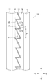
図1は、本実施形態の映像表示装置1を示す図である。図1(a)では、映像表示装置1の斜視図であり、図1(b)は、映像表示装置1を側面から見た図である。
映像表示装置1は、スクリーン10、映像源LS等を有している。本実施形態のスクリーン10は、映像源LSから投影された映像光Lを反射して、その映像源側の画面(表示面)に映像を表示可能である。このスクリーン10の詳細に関しては、後述する。
(Embodiment)
FIG. 1 is a diagram showing a video display device 1 of the present embodiment. FIG. 1A is a perspective view of the image display device 1, and FIG. 1B is a side view of the image display device 1.
The image display device 1 has a
ここで、理解を容易にするために、図1を含め以下に示す各図において、適宜、XYZ直交座標系を設けて示している。この座標系では、スクリーン10の画面左右方向(水平方向)をX方向、画面上下方向(鉛直方向)をY方向とし、スクリーン10の厚み方向をZ方向とする。スクリーン10の画面は、XY面に平行であり、スクリーン10の厚み方向(Z方向)は、スクリーン10の画面に直交する。
また、スクリーン10の映像源側の正面方向に位置する観察者O1から見て画面左右方向の右側に向かう方向を+X方向、画面上下方向の上側に向かう方向を+Y方向、厚み方向において背面側(裏面側)から映像源側に向かう方向を+Z方向とする。
さらに、以下の説明中において、画面上下方向、画面左右方向、厚み方向とは、特に断りが無い場合、このスクリーン10の使用状態における画面上下方向(鉛直方向)、画面左右方向(水平方向)、厚み方向(奥行き方向)であり、それぞれ、Y方向、X方向、Z方向に平行であるとする。
Here, in order to facilitate understanding, in each of the following figures including FIG. 1, an XYZ Cartesian coordinate system is appropriately provided and shown. In this coordinate system, the screen horizontal direction (horizontal direction) of the
Further, when viewed from the observer O1 located in the front direction of the image source side of the
Further, in the following description, the screen vertical direction, the screen horizontal direction, and the thickness direction are the screen vertical direction (vertical direction), the screen horizontal direction (horizontal direction), and the screen vertical direction (vertical direction) in the usage state of the
映像源LSは、映像光Lをスクリーン10へ投影する映像投射装置(プロジェクタ)である。本実施形態の映像源LSは、短焦点型のプロジェクタである。
この映像源LSは、映像表示装置1の使用状態において、スクリーン10の画面(表示領域)を映像源側(+Z側)の正面方向(スクリーン面の法線方向)から見た場合に、スクリーン10の画面左右方向の中央であって、スクリーン10の画面よりも鉛直方向下方側(−Y側)に位置している。
映像源LSは、奥行き方向(Z方向)において、スクリーン10の映像源側(+Z側)の表面からの距離が従来の汎用プロジェクタに比べて大幅に近い位置から、斜めに映像光Lを投影できる。したがって、従来の汎用プロジェクタに比べて、映像源LSは、スクリーン10までの投射距離が短く、投射された映像光がスクリーン10に入射する入射角度が大きく、入射角度の変化量(最小値から最大値までの変化量)も大きい。
The image source LS is an image projection device (projector) that projects the image light L onto the
This image source LS is a
The image source LS can project the image light L diagonally from a position in the depth direction (Z direction) where the distance from the surface of the
スクリーン10は、映像源LSが投射した映像光Lの一部を映像源側(+Z側)に位置する観察者O1側へ向けて反射して映像を表示する反射スクリーンであり、かつ、映像光を投射しない不使用時等において、スクリーン10の向こう側の景色を観察できる透明性を有する半透過型の反射スクリーンである。
スクリーン10の画面(表示領域)は、使用状態において、映像源側(+Z側)の観察者O1側から見て長辺方向が画面左右方向となる略矩形状である。
スクリーン10は、その画面サイズが対角40〜100インチ程度であり、画面の横縦比が16:9である。なお、これに限らず、スクリーン10は、例えば、画面サイズを40インチ以下としてもよく、使用目的や使用環境等に応じて、その大きさや形状は適宜選択できるものとする。
The
The screen (display area) of the
The screen size of the
一般的に、スクリーン10は、樹脂製の薄い層の積層体等であり、それ単独では平面性を維持するだけの十分な剛性を有していない場合が多い。そのため、本実施形態のスクリーン10は、その背面側に光透過性を有する不図示の接合層を介して不図示の支持板に一体に接合(あるいは部分固定)され、画面の平面性を維持する形態としてもよい。
このような支持板は、光透過性を有し、剛性が高い平板状の部材であり、アクリル樹脂やPC樹脂等の樹脂製、ガラス製等の板状の部材を用いることができる。また、これに限らず、スクリーン10は、不図示の枠部材等によってその四辺等が支持され、その平面性を維持する形態としてもよい。
本実施形態の映像表示装置1は、例えば、店舗等のショーウィンドウに適用される。このとき、スクリーン10は、ショーウィンドウの窓ガラス(ガラス板)を上記支持板として固定される形態とすることが好適である。
In general, the
Such a support plate is a flat plate-shaped member having light transmittance and high rigidity, and a plate-shaped member made of resin such as acrylic resin or PC resin or made of glass can be used. Further, the
The video display device 1 of the present embodiment is applied to, for example, a show window of a store or the like. At this time, it is preferable that the
図2は、本実施形態のスクリーン10の層構成を説明する図である。図2では、スクリーン10の映像源側(+Z側)の画面中央(画面の幾何学的中心)となる点A(図1参照)を通り、画面上下方向(Y方向)に平行であって、スクリーン面に垂直(厚み方向であるZ方向に平行)な断面の一部を拡大して示している。
図3は、本実施形態の第1光学形状層12を背面側(−Z側)から見た図である。理解を容易にするために、スクリーン10の反射層13や第2光学形状層14、保護層15等を省略して示している。
スクリーン10は、図2に示すように、その映像源側(+Z側)から順に、基材層11、第1光学形状層12、反射層13、第2光学形状層14、保護層15を備えている。
FIG. 2 is a diagram illustrating a layer structure of the
FIG. 3 is a view of the first
As shown in FIG. 2, the
基材層11は、光透過性を有するシート状の部材である。基材層11は、その背面側(裏面側,−Z側)に、第1光学形状層12が一体に形成されている。この基材層11は、第1光学形状層12を形成する基材(ベース)となる層である。
基材層11は、例えば、高い光透過性を有するPET(ポリエチレンテレフタレート)等のポリエステル樹脂、アクリル樹脂、スチレン樹脂、アクリルスチレン樹脂、PC(ポリカーボネート)樹脂、脂環式ポリオレフィン樹脂、TAC(トリアセチルセルロース)樹脂等により形成される。
また、基材層11は、スクリーン10の画面サイズ等に応じてその厚さを変更可能である。
The
The
Further, the thickness of the
第1光学形状層12は、基材層11の背面側(−Z側)に形成された光透過性を有する層である。第1光学形状層12の背面側の面には、単位光学形状(単位レンズ)121が複数配列されて設けられている。
単位光学形状121は、図3に示すように、第1光学形状層12をスクリーン面の法線方向背面側から見たときに、真円の一部形状(円弧状)であり、スクリーン10の画面(表示領域)外に位置する点Cを中心として、同心円状に複数配列されている。即ち、第1光学形状層12は、点Cを中心(フレネルセンター)とする、いわゆるオフセット構造のサーキュラーフレネルレンズ形状を背面側に有している。
この点Cは、図3に示すように、画面左右方向の中央であって画面下方に位置している。したがって、スクリーン10を正面方向から見た場合、点Cと点Aとは、画面上下方向(Y方向)に平行な同一直線上に位置している。
The first
As shown in FIG. 3, the unit
As shown in FIG. 3, this point C is located at the center in the left-right direction of the screen and at the lower side of the screen. Therefore, when the
単位光学形状121は、図2に示すように、スクリーン面に直交する方向(Z方向)に平行であって、単位光学形状121の配列方向に平行な断面における断面形状が、略三角形形状である。
この単位光学形状121は、背面側(−Z側)に凸であり、映像光が入射する第1斜面(レンズ面)121aと、これに対向する第2斜面(非レンズ面)121bとを有している。
図2に示す断面では、1つの単位光学形状121において、第2斜面121bは、頂点tを挟んで第1斜面121aの下側(−Y側)に位置している。
第1斜面121aがスクリーン面に平行な面となす角度は、θ1である。第2斜面121bがスクリーン面に平行な面となす角度は、θ2である。角度θ1,θ2は、θ2>θ1という関係を満たしている。
単位光学形状121の第1斜面121a及び第2斜面121bは、その表面に微細かつ不規則な凹凸形状を有する粗面である。この微細な凹凸形状は、凸形状と凹形状とが2次元方向に不規則に配列されて形成されており、凸形状及び凹形状は、その大きさや形状、高さ等は不規則である。
As shown in FIG. 2, the unit
The unit
In the cross section shown in FIG. 2, in one unit
The angle formed by the
The
単位光学形状121の配列ピッチは、Pであり、単位光学形状121の高さ(厚み方向における頂点tから単位光学形状121間の谷底となる点vまでの寸法)は、hである。
理解を容易にするために、図2では、単位光学形状121の配列ピッチP、角度θ1,θ2は、単位光学形状121の配列方向において一定である例を示している。しかし、本実施形態の単位光学形状121は、実際には、配列ピッチPは一定であるが、角度θ1が単位光学形状121の配列方向においてフレネルセンターとなる点Cから離れるにつれて次第に大きくなっている。
角度θ1,θ2、配列ピッチP等は、映像源LSからの映像光の投射角度(スクリーン10への映像光の入射角度)や、映像源LSの画素(ピクセル)の大きさ、スクリーン10の画面サイズ、各層の屈折率等に応じて、適宜設定してよい。例えば、単位光学形状121の配列方向に沿って、配列ピッチPが変化し、角度θ1,θ2が変化する形態としてもよい。
The arrangement pitch of the unit
For ease of understanding, FIG. 2 shows an example in which the arrangement pitch P and the angles θ1 and θ2 of the unit
The angles θ1 and θ2, the arrangement pitch P, and the like are the projection angle of the image light from the image source LS (angle of the image light incident on the screen 10), the size of the pixels of the image source LS, and the screen of the
第1光学形状層12は、光透過性の高いウレタンアクリレート系、ポリエステルアクリレート系、エポキシアクリレート系、ポリエーテルアクリレート系、ポリチオール系、ブタジエンアクリレート系等の紫外線硬化型樹脂により形成されている。
なお、本実施形態では、第1光学形状層12を構成する樹脂として、紫外線硬化型樹脂を例に挙げて説明するが、これに限らず、例えば、電子線硬化型樹脂等の他の電離放射線硬化型樹脂により形成してもよい。
The first
In the present embodiment, the ultraviolet curable resin will be described as an example of the resin constituting the first
また、本実施形態の第1光学形状層12は、ガラス転移温度Tgが50〜100℃である樹脂により形成されることが、第1光学形状層12と後述する反射層13との密着を高め、かつ、映像源側へ反射層13が反射する光へ十分な拡散反射作用を実現する観点から好ましい。また、第1光学形状層12を形成する樹脂のガラス転移温度Tgを上述の範囲とすることにより、後述する反射層13を単位光学形状121上に成膜する際に、単位光学形状121の表面が荒れ、反射層13の第1光学形状層12側の面、第2光学形状層14側の面でのヘイズ差を容易に付与することができ、スクリーン10の厚み方向において反射層13からスクリーン10の映像源側の表面までの領域が有する光の拡散作用を、反射層13からスクリーン10の背面側の表面までの領域が有する拡散作用よりも大きくすることができる。
Further, the first
なお、本実施形態では、第1光学形状層12の背面側(−Z側)の面には、サーキュラーフレネルレンズ形状が形成される例を示したが、これに限らず、第1光学形状層12の背面側の面には、単位光学形状121が画面左右方向(X方向)を長手方向とし、画面上下方向(Y方向)に配列されたリニアフレネルレンズ形状が形成される形態としてもよい。
In the present embodiment, an example in which a circular Frenel lens shape is formed on the back surface (−Z side) of the first
反射層13は、光を反射する機能を有する層であり、単位光学形状121上(第1斜面121a及び第2斜面121b上)に形成されている。
反射層13は、入射した光の一部を反射し、入射したその他の光の少なくとも一部を透過する半透過型の反射層、いわゆるハーフミラーである。
前述のように、第1斜面121a及び第2斜面121bには、微細かつ不規則な凹凸形状が形成されており、反射層13は、この凹凸形状に追従して形成され、第1斜面121a及び第2斜面121bの凹凸形状が維持されたまま成膜されている。そのため、反射層13の第1光学形状層12側(映像源側)の面及び第2光学形状層14側(背面側)の面は、微細かつ不規則な凹凸形状を有する粗面となっている。
この反射層13は、入射した光の一部を微細かつ不規則な凹凸形状により拡散反射し、入射したその他の光の少なくとも一部を拡散しないで透過するという機能を有する。
The
The
As described above, the
The
反射層13の反射率及び透過率は、所望する光学性能に合わせて適宜に設定できるが、映像光を良好に反射させるとともに、映像光以外の光(例えば、太陽光等の外界からの光)を良好に透過させる観点から、透過率が約30〜80%、反射率が約5〜60%の範囲であることが望ましい。
The reflectance and transmittance of the
反射層13は、光反射性の高い金属、例えば、アルミニウム、銀、ニッケル等により形成された薄膜である。本実施形態の反射層13は、アルミニウムを蒸着することにより形成されている。
なお、反射層13は、これに限らず、例えば、光反射性の高い金属をスパッタリングする等により形成されてもよい。また、反射層13は、誘電体多層膜を蒸着する等により形成されてもよい。
The
The
第2光学形状層14は、第1光学形状層12及び反射層13よりも背面側(−Z側)に設けられた光透過性を有する層である。第2光学形状層14は、第1光学形状層12の背面側の面を平坦にするために設けられており、単位光学形状121間の谷部を埋めるように形成されている。したがって、第2光学形状層14の映像源側(+Z側)の面は、第1光学形状層12の単位光学形状121の略逆型となる単位光学形状が複数配列されて形成されている。
このような第2光学形状層14を設けることにより、反射層13を保護でき、スクリーン10の背面側の面に保護層15等を積層しやすくなり、また、支持板等への接合も容易となる。
The second
By providing such a second
第2光学形状層14の屈折率は、第1光学形状層12の屈折率と等しい、又は、略等しい(等しいとみなせる程度に屈折率差が小さい)ことが望ましい。また、第2光学形状層14は、前述の第1光学形状層12と同じ紫外線硬化型樹脂を用いて形成することが好ましいが、異なる材料により形成してもよい。
本実施形態の第2光学形状層14は、前述の第1光学形状層12と同じ材料により形成され、その屈折率が第1光学形状層12の屈折率に等しい。
It is desirable that the refractive index of the second
The second
保護層15は、第2光学形状層14の背面側(−Z側)に形成された光透過性を有する層であり、このスクリーン10の背面側を保護する機能を有している。
保護層15は、光透過性の高い樹脂製のシート状の部材が用いられる。保護層15は、例えば、前述の基材層11と同様の材料を用いて形成されたシート状の部材を用いてもよい。
上述のように、本実施形態のスクリーン10は、光を拡散する拡散作用を有する粒子等の拡散材を含有した光拡散層を備えておらず、映像光等は、反射層13での反射時に、その表面の微細かつ不規則な凹凸形状によって拡散される。
The
As the
As described above, the
本実施形態のスクリーン10は、例えば、以下のような製造方法により製造される。
基材層11を用意し、その一方の面に、単位光学形状121を賦形する成形型に紫外線硬化型樹脂を充填した状態で積層し、紫外線を照射して紫外線硬化型樹脂を硬化させるUV成形法により第1光学形状層12を形成する。このとき、単位光学形状121を賦形する成形型の第1斜面121a及び第2斜面121bを賦形する面には、微細かつ不規則な凹凸形状が形成されている。この微細かつ不規則な凹凸形状は、成形型の第1斜面121a及び第2斜面121bを賦形する面に、表面加工を複数回行うことにより形成できる。この表面加工は、例えば、めっき加工や、エッチング加工、ブラスト加工等である。また、表面加工は、各種条件等を変更して複数回行ってもよい。
第1光学形状層12を基材層11の一方の面に形成した後、第1斜面121a及び第2斜面121bに、アルミニウムを蒸着することにより、反射層13を形成する。
The
A
After forming the first
その後、反射層13の上から、単位光学形状121による凹凸の谷部を充填して平面状となるように紫外線硬化型樹脂を塗布し、保護層15を積層し、紫外線を照射して紫外線硬化型樹脂を硬化させ、第2光学形状層14及び保護層15を一体に形成する。その後、所定の大きさに裁断する等により、スクリーン10が完成する。
なお、基材層11及び保護層15は、枚葉状としてもよいし、ウェブ状としてもよい。
After that, an ultraviolet curable resin is applied from above the
The
反射層13の表面に微細かつ不規則な凹凸形状を形成する方法として、例えば、第1斜面121a,第2斜面121b上に拡散粒子等を塗布してその上から反射層13を形成したり、第1光学形状層12を形成後に第1斜面121a,第2斜面121bにブラスト加工を行った後に、反射層13を形成したりする方法等が従来知られている。しかし、このような製法では、個々のスクリーン10での拡散特性や品質等のばらつきが大きく、安定した製造が行えない。
これに対して、上述のように、単位光学形状121の第1斜面121a,第2斜面121bの微細かつ不規則な凹凸形状を成形型によって賦形した後、反射層13を成膜することにより、多数のスクリーン10を製造する場合にも、品質のばらつきが少なく、安定して製造できる。
As a method of forming a fine and irregular uneven shape on the surface of the
On the other hand, as described above, the fine and irregular uneven shapes of the
図4は、本実施形態のスクリーン10での映像光及び外光の様子を示す図である。図4では、スクリーン10の画面中央となる点A(図1参照)を通り、単位光学形状121の配列方向(Y方向)及びスクリーンの厚み方向(Z方向)に平行な断面での断面の一部を拡大して示している。また、図4では、理解を容易にするために、スクリーン10内の各層の界面における屈折率差はないものとして示している。
スクリーン10の下方に位置する映像源LSから投射され、スクリーン10に入射した映像光L1のうち、一部の映像光L2は、その単位光学形状121の第1斜面121aに入射し、反射層13によって拡散反射され、観察者O1側へ出射する。
FIG. 4 is a diagram showing the state of image light and external light on the
Of the image light L1 projected from the image source LS located below the
第1斜面121aに入射した映像光のうち反射しなかった他の映像光L3は、反射層13を透過し、スクリーン10の背面側(−Z側)から出射する。このとき、映像光L3は、スクリーン10の上方へと出射し、スクリーン10の背面側の正面方向に位置する観察者O2には到達しない。
また、映像源LSから投射された映像光L1うち、一部の映像光L4は、スクリーン10の表面で反射するが、スクリーン10上方へ向かうので、観察者O1には届かず、映像の視認の妨げにはならない。
なお、本実施形態では、映像源LSがスクリーン10よりも下方に位置し、映像光L1がスクリーン10の下方から投射され、かつ、第2斜面121bの角度θ2(図2参照)がスクリーン10の画面上下方向の各点における映像光の入射角度よりも大きいので、映像光が第2斜面121bに直接入射することはなく、第2斜面121bは、映像光の反射にはほとんど影響しない。
Of the video light incident on the
Further, of the image light L1 projected from the image source LS, a part of the image light L4 is reflected on the surface of the
In the present embodiment, the image source LS is located below the
次に、背面側(−Z側)又は映像源側(+Z側)からスクリーン10に入射する映像光以外の太陽光等の外界からの光(以下、外光という)について説明する。
図4に示すように、スクリーン10に上方から入射する外光G1,G5のうち、一部の外光G2,G6は、スクリーン10の表面で反射し、スクリーン下方側へ向かう。また、一部の外光G3,G7は、反射層13で反射する。そして、例えば、外光G3の一部は、スクリーン10の映像源側(+Z側)の表面で全反射してスクリーン10内下方へ向かい、外光G3の他の一部(不図示)は、スクリーン10の下方へ向けて出射する。また、外光G7は、背面側(−Z側)のスクリーン外上方側へ出射する。また、反射層13で反射しなかった他の外光G4,G8は、反射層13を透過して、それぞれ背面側、映像源側へ出射する。このとき、映像源側へ出射する外光G2,G3,G8は、観察者O1には到達しないので、映像のコントラスト低下を抑制できる。
Next, light from the outside world such as sunlight (hereinafter referred to as external light) other than the image light incident on the
As shown in FIG. 4, of the external light G1 and G5 incident on the
また、スクリーン10に入射した外光の一部は、スクリーン10の映像源側及び背面側の表面で全反射して、スクリーン内部下方側へ向かい、減衰する。
また、スクリーン10に小さな入射角度で入射する外光G9,G10は、反射層13を透過して、それぞれ背面側、映像源側へ出射する。スクリーン10は、光を拡散する拡散粒子を含有する光拡散層を備えていないので、このスクリーン10を透過する外光G9,G10は、拡散されない。したがって、スクリーン10を通して、スクリーン10の向こう側の景色を観察した場合に、スクリーン10の向こう側の景色がぼやけたり、白くにじんだりすることなく、高い透明性を有して観察することができる。
Further, a part of the external light incident on the
Further, the external lights G9 and G10 incident on the
光を拡散する作用を有する拡散粒子等を含有する光拡散層を備えた従来の半透過型の反射スクリーンでは、映像光は、反射層での反射前後の2回拡散されるので、良好な視野角が得られる一方で映像の解像度が低下するという問題がある。また、拡散粒子等によって外光も拡散されるため、スクリーンの向こう側の景色がぼやけたり、白くにじんだりして観察され、透明性が低下する。 In a conventional semi-transmissive reflective screen provided with a light diffusing layer containing diffusing particles having a function of diffusing light, image light is diffused twice before and after reflection by the reflective layer, so that a good field of view is obtained. There is a problem that the resolution of the image is lowered while the corners are obtained. In addition, since external light is also diffused by diffused particles and the like, the scenery on the other side of the screen is observed to be blurred or bleeding white, and the transparency is lowered.
しかし、本実施形態のスクリーン10は、拡散粒子等を含有する光拡散層を備えておらず、映像光は、反射層13の表面が微細かつ不規則な凹凸形状により、反射時のみ拡散される。また、本実施形態のスクリーン10では、反射層13で反射する光のみが拡散され、透過光は拡散されない。
したがって、本実施形態のスクリーン10は、上述のように、良好な視野角及び解像度を有する映像を表示でき、かつ、スクリーン10の向こう側の景色が白くにじんだり、ぼけたりすることがなく観察者O1に良好に視認され、高い透明性を実現できる。また、本実施形態のスクリーン10では、スクリーン10に映像光が投射された状態においても、観察者O1が、スクリーン10の向こう側(背面側)の景色を一部視認することが可能である。さらに、本実施形態のスクリーン10では、背面側に位置する観察者O2は、映像光の投射の有無に関わらず、スクリーン10越しに映像源側(+Z側)の景色を高い透明性を有して良好に視認することができる。
However, the
Therefore, as described above, the
ここで、本実施形態のスクリーン10の光学特性についてさらに説明する。
本実施形態のスクリーン10は、厚み方向において、反射層13から背面側(−Z側)の表面までの領域が有する光の拡散作用が、反射層13から映像源側(+Z側)の表面までの領域が有する光の拡散作用よりも大きい。即ち、スクリーン10において、映像源側から入射した光が反射層13で反射して映像源側へ出射する場合に受ける拡散作用が、背面側から入射して反射層13で反射して背面側へ出射する場合に受ける拡散作用に比べて大きい。
したがって、スクリーン10の映像源側(+Z側)から入射して反射層13で反射して映像源側へ出射した反射光の拡散反射率(映像源側での拡散反射率)が、スクリーン10の背面側(−Z側)から入射して反射層13で反射して背面側へ出射した反射光の拡散反射率(背面側での拡散反射率)よりも大きい。
Here, the optical characteristics of the
In the
Therefore, the diffuse reflectance (diffuse reflectance on the image source side) of the reflected light incident from the image source side (+ Z side) of the
このような形態とすることにより、反射層13で反射する映像光を十分拡散でき、映像源側に位置する観察者O1に対して良好な視野角を有する映像を表示できる。また、映像源側上方からの外光に関しては、反射層13で拡散反射してもスクリーン10の下方へ向かい観察者O1に届かないので、映像のコントラストの低下を抑制できる。また、背面側上方からの外光に関しては、一部は反射層13によって拡散反射されるが、スクリーン10の上方へ出射する等して、背面側の観察者O2には届かないことに加え、拡散作用が映像源側に比べて小さいので、背面側から観察した場合のスクリーン10の透明性も維持できる。
With such a form, the image light reflected by the
本実施形態のスクリーン10の実施例及び比較例に相当するスクリーンを用意し、その映像の見えや透明性に関して評価した。
実施例のスクリーンは、映像源側でのヘイズが、背面側でのヘイズよりも大きい。即ち、実施例のスクリーンでは、映像源側から入射した場合の反射光の拡散反射率が9.2%であり、背面側から入射した場合の反射光の拡散反射率が5.8%であり、映像源側での拡散反射率の方が、背面側での拡散反射率よりも大きい。
また、比較例のスクリーンは、実施例のスクリーンと略同様の形態であるが、映像源側のヘイズと背面側のヘイズとが略等しい点が、実施例のスクリーンとは異なる。即ち、比較例のスクリーンでは、映像源側から入射した場合の反射光の拡散反射率が5.5%であり、背面側から入射した場合の反射光の拡散反射率が5.2%であり、背面側での拡散反射率と映像源側での拡散反射率が略同等である。
Screens corresponding to the examples and comparative examples of the
In the screen of the embodiment, the haze on the image source side is larger than the haze on the back side. That is, in the screen of the embodiment, the diffuse reflectance of the reflected light when incident from the image source side is 9.2%, and the diffuse reflectance of the reflected light when incident from the back surface side is 5.8%. , The diffuse reflectance on the image source side is larger than the diffuse reflectance on the back side.
Further, the screen of the comparative example has substantially the same form as the screen of the embodiment, but differs from the screen of the embodiment in that the haze on the image source side and the haze on the back side are substantially equal to each other. That is, in the screen of the comparative example, the diffuse reflectance of the reflected light when incident from the image source side is 5.5%, and the diffuse reflectance of the reflected light when incident from the back surface side is 5.2%. , The diffuse reflectance on the back side and the diffuse reflectance on the image source side are almost the same.
拡散反射率は、比較例及び実施例のスクリーンの画面中央となる点Aに対して画面上下方向において下側から入射角度8°で光を入射させた場合の反射光中における拡散反射光の割合を、ヘイズメーター(村上色彩製 HR−100)により、測定したものである。
映像の見えやスクリーンの透明性については、各測定例のスクリーンを明室環境下(照明はスクリーン中央部で約600ルクス程度)に配置し、映像源LSから映像光を投射し、スクリーンの正面方向3mの位置からその映像の見えや、スクリーンの透明性等を目視で観察し、評価した。
The diffuse reflectance is the ratio of diffuse reflected light in the reflected light when light is incident on the point A at the center of the screen of the screens of Comparative Examples and Examples from the lower side in the vertical direction of the screen at an incident angle of 8 °. Was measured with a haze meter (HR-100 manufactured by Murakami Color Co., Ltd.).
Regarding the appearance of the image and the transparency of the screen, the screen of each measurement example is placed in a bright room environment (lighting is about 600 lux in the center of the screen), the image light is projected from the image source LS, and the front of the screen. The appearance of the image and the transparency of the screen were visually observed and evaluated from a position of 3 m in the direction.
実施例のスクリーンは、明るく良好な映像が観察され、その視野角も十分であった。また、映像源側、背面側からスクリーンを観察した場合のスクリーンの透明性も高く、スクリーンの向こう側の景色が白く濁ることもなかった。
一方、比較例のスクリーンは、映像源側や背面側から観察した場合のスクリーンの透明性や映像の明るさ等は十分であったが、映像源側から観察した場合の視野角が小さく、スクリーンとしての使用には適さなかった。
On the screen of the example, a bright and good image was observed, and the viewing angle was sufficient. In addition, the transparency of the screen when observing the screen from the image source side and the back side was high, and the scenery on the other side of the screen did not become cloudy.
On the other hand, the screen of the comparative example had sufficient transparency and brightness of the screen when observed from the image source side or the back side, but the viewing angle when observed from the image source side was small, and the screen. It was not suitable for use as.
以上のことから、本実施形態のスクリーン10では、反射層13から映像源側の表面までの領域が有する光の拡散作用が、反射層13から背面側の表面までの領域が有する光の拡散作用よりも大きいので、透明性を維持しながら明るく、十分な視野角を有する良好な映像を表示できる。
また、本実施形態によれば、第1光学形状層12は、フレネルセンターとなる点Cが、表示領域外であって映像源LS側に位置しており、いわゆるオフセット構造のサーキュラーフレネルレンズ形状を有しているので、短焦点型のプロジェクタである映像源LSから投射された入射角度の大きい映像光Lであっても、画面左右方向の映像が暗くなることがなく、明るさの面均一性の高い良好な映像を表示することができる。
From the above, in the
Further, according to the present embodiment, in the first
(変形形態)
以上説明した実施形態に限定されることなく、種々の変形や変更が可能であって、それらも本発明の範囲内である。
(1)実施形態において、スクリーン10の映像源側(+Z側)の面に、傷つき防止を目的としたハードコート層を設けてもよい。ハードコート層は、例えば、スクリーン10の映像源側の面(基材層11の映像源側の面)に、ハードコート機能を有する紫外線硬化型樹脂(例えば、ウレタンアクリレート等)を塗布して形成する等により、形成される。
また、ハードコート層に限らず、スクリーン10の使用環境や使用目的等に応じて、例えば、反射防止機能、紫外線吸収機能、防汚機能、帯電防止機能等、適宜必要な機能を有する層を1つ又は複数選択して設けてもよい。さらに、基材層11の映像源側(+Z側)にタッチパネル層等を設けてもよい。
例えば、スクリーン10の映像源側の表面に反射防止層を設けた場合には、スクリーン10表面での反射を低減してスクリーン10への入射光量を増大させ、映像の明るさを向上させる効果に加え、反射層13で反射した光の一部が、映像源側表面で反射して背面側から出射することにより、背面側の観察者O2に映像が一部見えてしまうことを防止できる。
(Transformed form)
Not limited to the embodiments described above, various modifications and changes are possible, and these are also within the scope of the present invention.
(1) In the embodiment, a hard coat layer may be provided on the image source side (+ Z side) surface of the
Further, not limited to the hard coat layer, one layer having appropriately necessary functions such as antireflection function, ultraviolet absorption function, antifouling function, antistatic function, etc., depending on the usage environment and purpose of use of the
For example, when an antireflection layer is provided on the surface of the
(2)実施形態において、反射層13よりも映像源側(+Z側)に、光を透過するが、黒や灰色等の暗色系の着色材等で着色され、光吸収性を有する光吸収層を備える形態とし、映像の黒輝度の低減や映像源側からの外光吸収を図り、映像のコントラスト向上を図ってもよい。
また、実施形態において、反射層13よりも背面側に、上述のような光吸収層を設けて、背面側から入射する外光を吸収し、映像のコントラスト向上を図ってもよい。
なお、上述の光吸収層は、着色材を含有せず、透明な層であって光吸収作用を有する層としてもよい。
(2) In the embodiment, a light absorption layer that transmits light to the image source side (+ Z side) of the
Further, in the embodiment, the light absorption layer as described above may be provided on the back side of the
The light absorbing layer described above may be a transparent layer that does not contain a coloring material and has a light absorbing action.
(3)実施形態において、単位光学形状121の第1斜面121a及び第2斜面121bは、平面により形成される例を示したが、これに限らず、例えば、曲面と平面とが組み合わされた形態としてもよいし、折れ面状としてもよい。
また、単位光学形状121は、3つ以上の複数の面によって形成される多角形形状としてもよい。
また、反射層13は、第1斜面121a及び第2斜面121bに形成される例を示したが、これに限らず、例えば、第1斜面121aの少なくとも一部に形成される形態としてもよい。
また、第1斜面121a及び第2斜面121bは、微細な凹凸形状を有する例を示したが、これに限らず、第1斜面121aのみ微細な凹凸形状を有する形態としてもよい。
(3) In the embodiment, the
Further, the unit
Further, although the example in which the
Further, although the
(4)実施形態において、映像源LSは、スクリーン10の画面左右方向の中央であって画面外の下方に位置する例を挙げて説明したが、これに限らず、例えば、スクリーン10の斜め下側等に配置され、スクリーン10に対して画面左右方向において斜め方向光から映像光を投射する形態としてもよい。
この場合、第1光学形状層12のサーキュラーフレネルレンズ形状のフレネルセンターとなる点Cは、映像源LSの位置に合わせてずらして配置する。このような形態とすることにより、映像源LSの位置等を自由に設定することができる。
(4) In the embodiment, the image source LS has been described with reference to an example in which the image source LS is located at the center of the
In this case, the point C, which is the Fresnel center of the circular Fresnel lens shape of the first
(5)実施形態において、スクリーン10は、第1光学形状層12及び第2光学形状層14が十分な厚みや剛性等を有している場合には、基材層11及び保護層15を備えない形態としてもよいし、どちらか一方を備えない形態としてもよい。
また、スクリーン10は、基材層11及び保護層15の少なくとも一方を、ガラス板等の光透過性を有する板状の部材としてもよい。このとき、粘着剤層等を介して第1光学形状層12等がガラス板等に接合される形態としてもよい。
(5) In the embodiment, the
Further, in the
(6)実施形態において、映像源LSは、例えば、P波の偏光成分を有する映像光を投射するものとしてもよい。
このとき、映像源LSは、映像光が入射角φでスクリーン10へ投射されるように位置及び角度が設定されている。この入射角φは、スクリーン10へ投射された映像光(P波)の反射率がゼロとなる入射角(ブリュースター角)をφb(°)とした場合、(φb−10)°以上85°以下の範囲に設定される。例えば、スクリーン10へ投射された映像光の反射率がゼロとなる入射角φbが60°である場合、映像光の入射角φは、50〜85°の範囲に設定される。
(6) In the embodiment, the image source LS may project, for example, image light having a polarization component of a P wave.
At this time, the position and angle of the image source LS are set so that the image light is projected onto the
このように、P波の偏光成分を有する映像光を投射する映像源LSを用いることにより、スクリーン10への入射角φが大きい場合にも、スクリーン10の表面における鏡面反射を抑制することができ、映像源LSの設置位置等、投射系の設計の自由度を上げることができる。また、このような映像源LSを用いることにより、スクリーン10に入射する際にスクリーン表面での映像光の反射を低減でき、映像の明るさ、鮮明さの向上を図ることができる。
なお、角度φb(ブリュースター角)は、映像光が投射されるスクリーン10表面の材質により異なる。
また、このような形態の場合、基材層11及び保護層15としては、TAC製のシート状の部材が好適である。
In this way, by using the image source LS that projects the image light having the polarization component of the P wave, it is possible to suppress the specular reflection on the surface of the
The angle φb (Brewster's angle) differs depending on the material of the surface of the
Further, in such a form, a TAC sheet-like member is suitable as the
(7)実施形態において、映像表示装置1は、店舗等のショーウィンドウに適用される例を示したが、これに限らず、例えば、室内用のパーテーションや、展示会等における映像表示等にも適用できる。また、スクリーン10をフロントガラスに貼り合わせる等し、映像表示装置1を自動車のヘッドアップディスプレイ(HUD:HEAD−Up Display)に適用してもよいし、自動車以外の乗り物に適用してもよい。
(7) In the embodiment, the image display device 1 is applied to a show window of a store or the like, but the present invention is not limited to this, and is not limited to this, for example, for indoor partitions, image display at exhibitions, and the like. Applicable. Further, the image display device 1 may be applied to a head-up display (HUD: HEAD-Up Display) of an automobile by attaching the
なお、本実施形態及び変形形態は、適宜組み合わせて用いることもできるが、詳細な説明は省略する。また、本発明は以上説明した実施形態等によって限定されることはない。 Although the present embodiment and the modified form can be used in combination as appropriate, detailed description thereof will be omitted. Further, the present invention is not limited to the embodiments described above.
1 映像表示装置
10 スクリーン
11 基材層
12 第1光学形状層
121 単位光学形状
121a 第1斜面
121b 第2斜面
13 反射層
14 第2光学形状層
15 保護層
LS 映像源
1
Claims (8)
該反射スクリーン内に位置し、スクリーン面に沿って複数配列され、入射した光の一部を拡散反射し、入射したその他の光の少なくとも一部を透過する機能を有する反射層を備え、
前記反射層は、その両面が不規則な凹凸形状を有する粗面であり、
該反射スクリーンの厚み方向において、前記反射層から該反射スクリーンの映像源側表面までの領域が有する光の拡散作用は、前記反射層から該反射スクリーンの背面側表面までの領域が有する光の拡散作用よりも大きいこと、
を特徴とする反射スクリーン。 A reflective screen that reflects a part of the image light projected from the image source to display the image and transmits a part of it.
A reflective layer located within the reflective screen, arranged in plurality along the screen surface, having a function of diffuse-reflecting a part of incident light and transmitting at least a part of other incident light is provided.
The reflective layer is a rough surface having an irregular uneven shape on both sides thereof.
In the thickness direction of the reflective screen, the light diffusing action of the region from the reflective layer to the image source side surface of the reflective screen is the light diffusing effect of the region from the reflective layer to the back surface of the reflective screen. Greater than action,
A reflective screen featuring.
該反射スクリーンの厚み方向において、映像源側から入射した光が前記反射層で反射して映像源側へ出射した反射光における拡散反射率は、背面側から入射した光が前記反射層で反射して背面側へ出射した反射光における拡散反射率よりも大きいこと、
を特徴とする反射スクリーン。 In the reflective screen according to claim 1,
In the thickness direction of the reflective screen, the light incident from the image source side is reflected by the reflection layer and the diffuse reflectance of the reflected light emitted to the image source side is such that the light incident from the back surface side is reflected by the reflection layer. It is larger than the diffuse reflectance of the reflected light emitted to the back side.
A reflective screen featuring.
該反射スクリーン内に位置し、スクリーン面に沿って複数配列され、入射した光の一部を拡散反射し、入射したその他の光の少なくとも一部を透過する機能を有する反射層を備え、A reflective layer located within the reflective screen, arranged in plurality along the screen surface, having a function of diffuse-reflecting a part of incident light and transmitting at least a part of other incident light is provided.
前記反射層は、その両面が不規則な凹凸形状を有する粗面であり、The reflective layer is a rough surface having an irregular uneven shape on both sides thereof.
該反射スクリーンの厚み方向において、映像源側から入射した光が前記反射層で反射して映像源側へ出射した反射光における拡散反射率は、背面側から入射した光が前記反射層で反射して背面側へ出射した反射光における拡散反射率よりも大きいこと、In the thickness direction of the reflective screen, the light incident from the image source side is reflected by the reflection layer and the diffuse reflectance of the reflected light emitted to the image source side is such that the light incident from the back surface side is reflected by the reflection layer. It is larger than the diffuse reflectance of the reflected light emitted to the back side.
を特徴とする反射スクリーン。A reflective screen featuring.
前記反射層は、金属薄膜により形成されていること、
を特徴とする反射スクリーン。 In the reflective screen according to any one of claims 1 to 3.
The reflective layer is formed of a metal thin film.
A reflective screen featuring.
光透過性を有し、映像光が入射する第1の面とこれに対向する第2の面とを有する単位光学形状が、背面側の面に複数配列された第1光学形状層と、
光透過性を有し、前記第1光学形状層よりも背面側に設けられ、前記単位光学形状の逆型となる単位光学形状が映像源側の面に複数配列された第2光学形状層と、
を備え、
前記反射層は、前記第1光学形状層と前記第2光学形状層との間であって、少なくとも前記単位光学形状の前記第1の面の一部に位置すること、
を特徴とする反射スクリーン。 In the reflective screen according to any one of claims 1 to 4.
A first optical shape layer having a plurality of unit optical shapes having light transmission and having a first surface on which image light is incident and a second surface facing the first surface and a second surface facing the first surface are arranged on the back surface side.
A second optical shape layer having light transmission, provided on the back side of the first optical shape layer, and having a plurality of unit optical shapes arranged on the surface on the image source side, which is the reverse of the unit optical shape. ,
With
The reflective layer is located between the first optical shape layer and the second optical shape layer and at least on a part of the first surface of the unit optical shape.
A reflective screen featuring.
前記第1光学形状層は、ガラス転移温度Tgが50〜100℃である樹脂により形成されていること、The first optical shape layer is formed of a resin having a glass transition temperature Tg of 50 to 100 ° C.
を特徴とする反射スクリーン。A reflective screen featuring.
光を拡散する作用を有する拡散粒子を含有する光拡散層を備えていないこと、
を特徴とする反射スクリーン。 In the reflective screen according to any one of claims 1 to 6.
Not having a light diffusing layer containing diffusing particles that have the effect of diffusing light,
A reflective screen featuring.
前記反射スクリーンに映像光を投射する映像源と、
を備える映像表示装置。 The reflective screen according to any one of claims 1 to 7.
An image source that projects image light onto the reflective screen,
A video display device comprising.
Priority Applications (1)
| Application Number | Priority Date | Filing Date | Title |
|---|---|---|---|
| JP2017023126A JP6957891B2 (en) | 2017-02-10 | 2017-02-10 | Reflective screen, video display device |
Applications Claiming Priority (1)
| Application Number | Priority Date | Filing Date | Title |
|---|---|---|---|
| JP2017023126A JP6957891B2 (en) | 2017-02-10 | 2017-02-10 | Reflective screen, video display device |
Publications (2)
| Publication Number | Publication Date |
|---|---|
| JP2018128636A JP2018128636A (en) | 2018-08-16 |
| JP6957891B2 true JP6957891B2 (en) | 2021-11-02 |
Family
ID=63172846
Family Applications (1)
| Application Number | Title | Priority Date | Filing Date |
|---|---|---|---|
| JP2017023126A Active JP6957891B2 (en) | 2017-02-10 | 2017-02-10 | Reflective screen, video display device |
Country Status (1)
| Country | Link |
|---|---|
| JP (1) | JP6957891B2 (en) |
Families Citing this family (1)
| Publication number | Priority date | Publication date | Assignee | Title |
|---|---|---|---|---|
| JP6848501B2 (en) * | 2017-02-14 | 2021-03-24 | 大日本印刷株式会社 | Reflective screen, video display device |
Family Cites Families (6)
| Publication number | Priority date | Publication date | Assignee | Title |
|---|---|---|---|---|
| JPH09114003A (en) * | 1995-10-19 | 1997-05-02 | Toppan Printing Co Ltd | Projection screen |
| FR2991064B1 (en) * | 2012-05-25 | 2014-05-16 | Saint Gobain | METHOD FOR PROJECTING OR RETROPROJECTING ON A GLAZING COMPRISING A TRANSPARENT LAYER ELEMENT HAVING DIFFUSED REFLECTION PROPERTIES |
| GB201304114D0 (en) * | 2013-03-07 | 2013-04-24 | The Technology Partnership Plc | Embedded diffuser structure |
| JP2015060193A (en) * | 2013-09-20 | 2015-03-30 | 大日本印刷株式会社 | Reflection type screen, and video display system |
| JP2016109894A (en) * | 2014-12-08 | 2016-06-20 | 旭硝子株式会社 | Video display transparent member, video display system, and video display method |
| JP2016151649A (en) * | 2015-02-17 | 2016-08-22 | 大日本印刷株式会社 | Reflection screen and video display system |
-
2017
- 2017-02-10 JP JP2017023126A patent/JP6957891B2/en active Active
Also Published As
| Publication number | Publication date |
|---|---|
| JP2018128636A (en) | 2018-08-16 |
Similar Documents
| Publication | Publication Date | Title |
|---|---|---|
| JP7060137B2 (en) | Reflective screen, video display device | |
| JP6812761B2 (en) | Reflective screen, video display device | |
| JP7081705B2 (en) | Reflective screen, video display device | |
| JP2017156452A (en) | Reflective screen and image display device | |
| JP2017211454A (en) | Screen and image display device | |
| JP6642043B2 (en) | Reflective screen, video display | |
| JP6790616B2 (en) | Reflective screen, video display device | |
| JP2018109687A (en) | Reflection screen and video display device | |
| JP6988070B2 (en) | Video display device | |
| JP6953728B2 (en) | Screen, video display device | |
| JP6988069B2 (en) | Reflective screen, video display device | |
| JP6593201B2 (en) | Screen, video display device | |
| JP6812757B2 (en) | Video display device | |
| JP6938872B2 (en) | Video display device | |
| JP6957891B2 (en) | Reflective screen, video display device | |
| JP6724424B2 (en) | Reflective screen, video display | |
| JP6717052B2 (en) | Reflective screen, video display | |
| JP7036247B2 (en) | Reflective screen, video display device | |
| JP2018013634A (en) | Transmission type screen, and rear surface projection type display device | |
| JP2017156696A (en) | Reflection screen and image display device | |
| JP7070613B2 (en) | Video display device | |
| JP7001132B2 (en) | Transmissive screen, rear projection display device | |
| JP7238602B2 (en) | reflective screen, video display | |
| JP7322511B2 (en) | Transmissive screen, image display device | |
| JP2017187701A (en) | Transmission type screen and rear projection type display device |
Legal Events
| Date | Code | Title | Description |
|---|---|---|---|
| A621 | Written request for application examination |
Free format text: JAPANESE INTERMEDIATE CODE: A621 Effective date: 20191225 |
|
| A977 | Report on retrieval |
Free format text: JAPANESE INTERMEDIATE CODE: A971007 Effective date: 20201218 |
|
| A131 | Notification of reasons for refusal |
Free format text: JAPANESE INTERMEDIATE CODE: A131 Effective date: 20210202 |
|
| A521 | Written amendment |
Free format text: JAPANESE INTERMEDIATE CODE: A523 Effective date: 20210317 |
|
| TRDD | Decision of grant or rejection written | ||
| A01 | Written decision to grant a patent or to grant a registration (utility model) |
Free format text: JAPANESE INTERMEDIATE CODE: A01 Effective date: 20210907 |
|
| A61 | First payment of annual fees (during grant procedure) |
Free format text: JAPANESE INTERMEDIATE CODE: A61 Effective date: 20210920 |
|
| R150 | Certificate of patent or registration of utility model |
Ref document number: 6957891 Country of ref document: JP Free format text: JAPANESE INTERMEDIATE CODE: R150 |