JP6956616B2 - Rope tester, wire rope analyzer and its control program - Google Patents
Rope tester, wire rope analyzer and its control program Download PDFInfo
- Publication number
- JP6956616B2 JP6956616B2 JP2017237676A JP2017237676A JP6956616B2 JP 6956616 B2 JP6956616 B2 JP 6956616B2 JP 2017237676 A JP2017237676 A JP 2017237676A JP 2017237676 A JP2017237676 A JP 2017237676A JP 6956616 B2 JP6956616 B2 JP 6956616B2
- Authority
- JP
- Japan
- Prior art keywords
- wire rope
- detector
- magnetization detector
- output signal
- magnetization
- Prior art date
- Legal status (The legal status is an assumption and is not a legal conclusion. Google has not performed a legal analysis and makes no representation as to the accuracy of the status listed.)
- Active
Links
Images


Classifications
-
- G—PHYSICS
- G01—MEASURING; TESTING
- G01N—INVESTIGATING OR ANALYSING MATERIALS BY DETERMINING THEIR CHEMICAL OR PHYSICAL PROPERTIES
- G01N21/00—Investigating or analysing materials by the use of optical means, i.e. using sub-millimetre waves, infrared, visible or ultraviolet light
- G01N21/84—Systems specially adapted for particular applications
- G01N21/88—Investigating the presence of flaws or contamination
- G01N21/95—Investigating the presence of flaws or contamination characterised by the material or shape of the object to be examined
- G01N21/952—Inspecting the exterior surface of cylindrical bodies or wires
-
- G—PHYSICS
- G01—MEASURING; TESTING
- G01N—INVESTIGATING OR ANALYSING MATERIALS BY DETERMINING THEIR CHEMICAL OR PHYSICAL PROPERTIES
- G01N27/00—Investigating or analysing materials by the use of electric, electrochemical, or magnetic means
- G01N27/72—Investigating or analysing materials by the use of electric, electrochemical, or magnetic means by investigating magnetic variables
- G01N27/82—Investigating or analysing materials by the use of electric, electrochemical, or magnetic means by investigating magnetic variables for investigating the presence of flaws
-
- G—PHYSICS
- G01—MEASURING; TESTING
- G01N—INVESTIGATING OR ANALYSING MATERIALS BY DETERMINING THEIR CHEMICAL OR PHYSICAL PROPERTIES
- G01N21/00—Investigating or analysing materials by the use of optical means, i.e. using sub-millimetre waves, infrared, visible or ultraviolet light
- G01N21/84—Systems specially adapted for particular applications
- G01N21/88—Investigating the presence of flaws or contamination
- G01N21/89—Investigating the presence of flaws or contamination in moving material, e.g. running paper or textiles
- G01N21/8901—Optical details; Scanning details
-
- G—PHYSICS
- G01—MEASURING; TESTING
- G01N—INVESTIGATING OR ANALYSING MATERIALS BY DETERMINING THEIR CHEMICAL OR PHYSICAL PROPERTIES
- G01N21/00—Investigating or analysing materials by the use of optical means, i.e. using sub-millimetre waves, infrared, visible or ultraviolet light
- G01N21/84—Systems specially adapted for particular applications
- G01N21/88—Investigating the presence of flaws or contamination
- G01N21/89—Investigating the presence of flaws or contamination in moving material, e.g. running paper or textiles
- G01N21/892—Investigating the presence of flaws or contamination in moving material, e.g. running paper or textiles characterised by the flaw, defect or object feature examined
-
- G—PHYSICS
- G01—MEASURING; TESTING
- G01N—INVESTIGATING OR ANALYSING MATERIALS BY DETERMINING THEIR CHEMICAL OR PHYSICAL PROPERTIES
- G01N27/00—Investigating or analysing materials by the use of electric, electrochemical, or magnetic means
- G01N27/72—Investigating or analysing materials by the use of electric, electrochemical, or magnetic means by investigating magnetic variables
- G01N27/82—Investigating or analysing materials by the use of electric, electrochemical, or magnetic means by investigating magnetic variables for investigating the presence of flaws
- G01N27/83—Investigating or analysing materials by the use of electric, electrochemical, or magnetic means by investigating magnetic variables for investigating the presence of flaws by investigating stray magnetic fields
-
- G—PHYSICS
- G01—MEASURING; TESTING
- G01N—INVESTIGATING OR ANALYSING MATERIALS BY DETERMINING THEIR CHEMICAL OR PHYSICAL PROPERTIES
- G01N21/00—Investigating or analysing materials by the use of optical means, i.e. using sub-millimetre waves, infrared, visible or ultraviolet light
- G01N21/84—Systems specially adapted for particular applications
- G01N21/88—Investigating the presence of flaws or contamination
- G01N21/8851—Scan or image signal processing specially adapted therefor, e.g. for scan signal adjustment, for detecting different kinds of defects, for compensating for structures, markings, edges
- G01N2021/8854—Grading and classifying of flaws
- G01N2021/8867—Grading and classifying of flaws using sequentially two or more inspection runs, e.g. coarse and fine, or detecting then analysing
Description
この発明はワイヤロープを検査するロープテスタに関する。またこの発明はワイヤロープ解析装置およびその制御プログラムに関する。 The present invention relates to a rope tester for inspecting wire rope. The present invention also relates to a wire rope analyzer and a control program thereof.
ワイヤロープは定期的に検査しなければならない。たとえばエレベータ用ワイヤロープの検査では,エレベータが設置されているビル等に検査員が派遣され,現場において検査員によってエレベータ用ワイヤロープが検査される。 Wire ropes must be inspected on a regular basis. For example, in the inspection of elevator wire ropes, inspectors are dispatched to buildings where elevators are installed, and the inspectors inspect the elevator wire ropes at the site.
特許文献1は,エレベータ用ワイヤロープを撮像した映像信号を用いて,素線に所定の大きさまたは所定長さの摩耗足が所定数あるか否かを検出する検査装置を開示する。
映像信号を用いて摩耗足が発生している箇所を事前に特定することができれば,その後の作業員による検査がスムーズになる。しかしながら,特許文献1では,画像処理(パターン認識)によって摩耗足があるか否かが検出されるので,ワイヤロープが汚れていると映像が不明瞭となり,画像処理に基づく摩耗足の検出が難しくなる可能性が大きい。特許文献1は映像を明瞭にするためにワイヤロープを洗浄することも記載するが,これではワイヤロープの撮像するたびに,撮像に先立ってワイヤロープを洗浄し,さらにそれを終えた後にグリース等を塗布することが必要になるので,作業負担が増大してしまう。
If the location where the worn foot is generated can be identified in advance using the video signal, the subsequent inspection by the worker will be smooth. However, in
この発明は,作業負担を増大させることなく,ワイヤロープの状況を事前に把握できるようにすることを目的とする。 An object of the present invention is to make it possible to grasp the situation of the wire rope in advance without increasing the work load.
この発明によるロープテスタは,所定速度で移動するワイヤロープを検査するためのものであって,磁力を発生する磁化器,および磁化器によって発生した磁力によって磁化される上記ワイヤロープから生じる磁気変化を検出する検出器を含む磁化検出器,上記ワイヤロープの移動方向に上記磁化検出器との間に所定間隔をあけて設けられ,上記ワイヤロープを撮影する撮影装置,ならびに上記磁化検出器および上記撮影装置に接続され,上記磁化検出器によって検出される磁気変化に基づいて上記ワイヤロープの欠陥箇所を検出し,上記欠陥箇所が上記撮影装置の設置箇所に至るタイミングに上記撮影装置を駆動する駆動信号を出力する制御器を備えている。 The rope tester according to the present invention is for inspecting a wire rope moving at a predetermined speed, and detects a magnetizer that generates a magnetic force and a magnetic change generated from the wire rope magnetized by the magnetic force generated by the magnetizer. A magnetization detector including a detector to detect, a photographing device provided at a predetermined interval from the magnetization detector in the moving direction of the wire rope, and photographing the wire rope, and the magnetization detector and the photographing. A drive signal that is connected to the device, detects a defective portion of the wire rope based on the magnetic change detected by the magnetization detector, and drives the imaging device at a timing when the defective portion reaches the installation location of the imaging device. It is equipped with a controller that outputs.
磁化検出器はたとえば磁気変化に基づく電圧値を表す出力信号を出力することができ,欠陥箇所の出力信号(電圧値)は欠陥のない箇所の出力信号(電圧値)よりも大きな値となる。制御器は典型的には所定の閾値を超える出力信号を判定することによって欠陥箇所を検出する。 The magnetization detector can output, for example, an output signal representing a voltage value based on a magnetic change, and the output signal (voltage value) at the defective portion is larger than the output signal (voltage value) at the defective portion. The controller typically detects the defect by determining an output signal that exceeds a predetermined threshold.
この発明によると,磁化検出器によって検出される磁気変化に基づいて所定速度で移動するワイヤロープの欠陥箇所が検出され,その欠陥箇所が撮影装置によって撮影される。撮影装置はワイヤロープの移動方向に磁化検出器との間に所定間隔をあけて設けられているので,ワイヤロープの欠陥箇所は,はじめに磁化検出器を通り,所定時間経過後に撮影装置に至る。制御器によって,上記欠陥箇所が上記撮影装置の設置箇所に至るタイミングで上記撮影装置が駆動されるので,上記磁化検出器によって検出される欠陥箇所を撮影装置によって正しく撮影することができる。磁化検出器によって検出される欠陥箇所をピンポイントに撮影した画像が取得されるから,ワイヤロープの状況を正しくかつ詳しく把握することができる。 According to the present invention, a defective portion of a wire rope moving at a predetermined speed is detected based on a magnetic change detected by a magnetization detector, and the defective portion is photographed by an imaging device. Since the photographing device is provided at a predetermined distance from the magnetization detector in the moving direction of the wire rope, the defective portion of the wire rope first passes through the magnetization detector and reaches the photographing device after a predetermined time elapses. Since the imaging device is driven by the controller at the timing when the defective portion reaches the installation location of the imaging device, the defective portion detected by the magnetization detector can be correctly imaged by the imaging device. Since a pinpoint image of the defect detected by the magnetization detector is acquired, the condition of the wire rope can be grasped correctly and in detail.
一実施態様では,上記制御器が,上記ワイヤロープの所定の移動速度,および上記磁化検出器と上記撮像装置の間の所定間隔を表す距離の入力を受け付ける入力部,ならびに上記入力部から受け付けられる移動速度と所定間隔を表す距離とを用いて,上記駆動信号を出力すべきタイミングを規定する遅延時間を算出する遅延時間算出手段を備えている。上記磁化検出器による欠陥検出のタイミングから算出される遅延時間を経過したタイミングに,制御装置から撮像装置の駆動信号が出力される。入力されるワイヤロープの移動速度および磁化検出器と撮像装置の間の所定間隔を表す距離に基づいて遅延時間が算出されるので,ワイヤロープの移動速度および磁化検出器と撮像装置の間の所定間隔を表す距離が異なっても(たとえばエレベータ用ワイヤロープの移動速度は,エレベータごとに異なる),欠陥箇所をピンポイントに正しく撮影するための遅延時間を算出することができる。 In one embodiment, the controller receives from an input unit that receives input of a predetermined moving speed of the wire rope and a distance representing a predetermined distance between the magnetization detector and the imaging device, and an input unit. A delay time calculation means for calculating a delay time that defines a timing at which the drive signal should be output is provided by using a moving speed and a distance representing a predetermined interval. The drive signal of the imaging device is output from the control device at the timing when the delay time calculated from the timing of defect detection by the magnetization detector has elapsed. Since the delay time is calculated based on the input wire rope movement speed and the distance representing the predetermined distance between the magnetization detector and the image pickup device, the wire rope movement speed and the predetermined distance between the magnetization detector and the image pickup device are calculated. Even if the distance representing the interval is different (for example, the moving speed of the wire rope for the elevator is different for each elevator), the delay time for correctly pinpointing the defective part can be calculated.
もっとも,磁化検出器と撮影装置の間の距離が固定距離であれば,ワイヤロープの移動速度のみを入力部に入力すれば十分であるのは言うまでもない。磁化検出器と撮影装置の間の固定距離を表すデータは,たとえばあらかじめ記憶装置に記憶させておけばよい。 However, if the distance between the magnetization detector and the imaging device is a fixed distance, it goes without saying that it is sufficient to input only the moving speed of the wire rope to the input unit. Data representing a fixed distance between the magnetization detector and the photographing device may be stored in a storage device in advance, for example.
好ましくは,上記制御器が,上記磁化検出器から出力される出力信号を所定時間間隔ごとに時系列に記憶手段に記録する第1の記録手段,および上記撮影装置から出力される画像データを撮影順番を含めて記憶手段に記録する第2の記録手段を備えている。画像データの撮影順番の記録は,記憶手段における画像データの記録順番に基づくものであってもよいし,ファイル名,ヘッダ情報等に順番を表すデータを付随させることに基づくものであってもよい。第1の記録手段によって記憶手段に記録される磁化検出器から出力される出力信号および第2の記録手段によって記憶手段に記録される画像データの両方を,ワイヤロープの状況把握に利用することができる。 Preferably, the controller captures the first recording means that records the output signal output from the magnetization detector in the storage means in time series at predetermined time intervals, and the image data output from the photographing device. It is provided with a second recording means for recording in the storage means including the order. The recording of the shooting order of the image data may be based on the recording order of the image data in the storage means, or may be based on attaching data indicating the order to the file name, header information, or the like. .. Both the output signal output from the magnetization detector recorded in the storage means by the first recording means and the image data recorded in the storage means by the second recording means can be used for grasping the situation of the wire rope. can.
この発明は,上記ロープテスタによって記録される上記磁化検出器からの出力信号および上記撮影装置からの画像データが与えられるワイヤロープ解析装置も提供する。この発明によるワイヤロープ解析装置は,横軸をワイヤロープ位置,縦軸を磁化検出器から出力される出力信号とするグラフを表示するグラフ表示手段,ならびに上記グラフ表示手段によって表示される出力信号を表すグラフのうち上記欠陥箇所を表すグラフに対応づけて,上記画像データによって表されるワイヤロープ画像を表示するワイヤロープ画像表示手段を備えている。 The present invention also provides a wire rope analysis device to which an output signal from the magnetization detector recorded by the rope tester and image data from the photographing device are given. The wire rope analyzer according to the present invention displays a graph display means in which the horizontal axis is the wire rope position and the vertical axis is the output signal output from the magnetization detector, and the output signal displayed by the graph display means. A wire rope image display means for displaying a wire rope image represented by the image data is provided in association with the graph representing the defect portion among the graphs to be represented.
磁化検出器から出力される出力信号は所定時間間隔ごとに時系列に記憶手段に記憶され,またワイヤロープは所定速度で移動するので,出力信号のそれぞれをグラフの横軸(ワイヤロープ位置)に対応づけることができる。 The output signal output from the magnetization detector is stored in the storage means in time series at predetermined time intervals, and the wire rope moves at a predetermined speed, so each output signal is on the horizontal axis (wire rope position) of the graph. Can be associated.
記憶手段に記録される画像データは欠陥箇所をピンポイントに撮影することによって作成されるものであり,また上記撮影装置から出力される画像データは撮影順番を含めて記憶手段に記録されるので,出力信号のグラフに含まれる欠陥箇所を表すグラフのそれぞれに画像データを正しく対応づけることができる(欠陥箇所を表すグラフのそれぞれについて,検査開始箇所から検査終了箇所に向けて,古い順番に画像データを対応づければよい)。出力信号のグラフからワイヤロープにおける欠陥箇所および程度(出力信号の大きさ)が把握されるのみならず,その外観も画像確認することができる。磁化検出器のみを用いた場合には把握しにくいたとえば断線間隔,断線本数といった,より具体的なワイヤロープの状況を詳細に確認することができる。 The image data recorded in the storage means is created by pinpointing the defective portion, and the image data output from the photographing device is recorded in the storage means including the shooting order. Image data can be correctly associated with each of the graphs showing the defective parts included in the graph of the output signal (for each of the graphs showing the defective parts, the image data is in chronological order from the inspection start point to the inspection end point. Should be associated). From the graph of the output signal, not only the defect location and degree (magnitude of the output signal) of the wire rope can be grasped, but also the appearance can be confirmed as an image. It is possible to confirm in detail more specific wire rope conditions such as the disconnection interval and the number of disconnections, which are difficult to grasp when only the magnetization detector is used.
この発明は,上述したワイヤロープ解析装置を制御するプログラムも提供する。 The present invention also provides a program for controlling the wire rope analyzer described above.
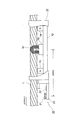
図1はロープテスタの全体構成を示す斜視図である。図2はロープテスタを構成する,以下に説明する磁化検出器および画像撮影ユニットを,側方から概略的に示すブロック図である。図2においては磁化検出器の内部構造が示されている。 FIG. 1 is a perspective view showing the overall configuration of the rope tester. FIG. 2 is a block diagram schematically showing the magnetization detector and the imaging unit described below, which constitute the rope tester, from the side. FIG. 2 shows the internal structure of the magnetization detector.
ロープテスタは,磁化検出器10,画像撮影ユニット20,制御器30,およびコンピュータ装置40を備えている。
The rope tester includes a
磁化検出器10は,検査対象であるエレベータ用ワイヤロープ1の一部を磁化してエレベータ用ワイヤロープ1の一部を含む磁気回路を形成するとともに,エレベータ用ワイヤロープ1に欠陥が存在することによって生じる磁気抵抗の変化を,磁束または磁束の変化を用いて観察するものである。
The
図1を参照して,磁化検出器10は,横断面が概略半円形の,一方向にのびるワイヤロープ通過凹部11を備えている。ワイヤロープ通過凹部11内に断面円形のワイヤロープ1が通される。磁化検出器10(ワイヤロープ通過凹部11)の長手方向の長さは,たとえば 160mm程度である。
With reference to FIG. 1, the
図2を参照して,ワイヤロープ通過凹部11の下方に,直方体状のヨーク12と,上記ヨーク12の上面の両側部に固定された1対の磁石13,14と,上記1対の磁石13,14の間に配置され,磁石13,14のそれぞれと間隔をあけて上記ヨーク12の上面に固定されたコイルベース15と,上記コイルベース15の上面に固定された検出コイル16が設けられている。検出コイル16はワイヤロープ1の外周面の大部分を検査するために,ワイヤロープ通過凹部11に沿うようにU字形に湾曲している。磁石13,14,ヨーク12,および磁石13,14によって挟まれる範囲のワイヤロープ1の一部によって,磁気回路が構成される。
With reference to FIG. 2, below the wire rope passage recess 11, a rectangular
ワイヤロープ1に損傷(欠損)があると,損傷箇所においてワイヤロープ1の断面積が減少し,磁気回路における磁気抵抗が増加する。磁気抵抗の増加は上述した磁気回路における磁束を減少させる。磁気回路を流れる磁束は検出コイル16と鎖交するので,磁束の変化にしたがって検出コイル16には起電力が生じる。検出コイル16から出力される電圧信号に基づいて,ワイヤロープ1に発生している損傷を定量的に評価することができる。
If the
また,ワイヤロープ1に鉄粉の堆積などの異物が付着していると,その箇所においても磁束が変化し,検出コイル16に起電力が生じる。鉄粉が堆積している箇所は断面積が増えるので,上述した損傷がワイヤロープ1に存在する場合に生じる起電力と極性の異なる起電力が検出コイル16に生じることになる。検出コイル16から出力される電圧信号は,ワイヤロープ1に付着している異物検出にも用いることができる。
Further, if foreign matter such as iron powder is attached to the
以下の説明において,ワイヤロープ1の損傷(欠損)およびワイヤロープ1への異物付着を,包括的に「欠陥」と呼ぶ。
In the following description, damage (deficiency) of the
画像撮影ユニット20は,台座23上に固定されたデジタルカメラ21および照明源22を備えている。デジタルカメラ21および照明源22はいずれもワイヤロープ1の方向を向いており,照明源22によって明るくされたワイヤロープ1の表面をデジタルカメラ21によって撮影することができる。
The
磁化検出器10と画像撮影ユニット20との間にはアタッチメント2が設けられており,このアタッチメント2を介して磁化検出器10と画像撮影ユニット20を一体化することができる。
An
上述した磁化検出器10,デジタルカメラ21および照明源22と,以下に説明するコンピュータ装置40とが,信号線によって制御器30に接続されている。
The
制御器30は,CPU(Central Processing Unit ),メモリ,ハードディスク,通信インターフェース(いずれも図示略)等を備えるもので,磁化検出器10(検出コイル16)から出力される電圧信号の受信および記録,上記デジタルカメラ21への電源供給および駆動(撮影指示),デジタルカメラ21から出力される画像データの受信および記録,照明源22への電源供給,コンピュータ装置40へのデータ送信を行う。
The
制御器30が備えるメモリに,磁化検出器10(検出コイル16)から出力される電圧信号,デジタルカメラ21から送信される画像データ,オペレータによって設定される設定データ(測定日時,ワイヤロープ1の移動速度(ロープスピード),ワイヤロープ1の直径,ゲイン設定値,欠陥判定のための閾値(判定レベル),検出コイル16とデジタルカメラ21の間の距離など)が記録される。設定データの入力に制御器30が備える入力装置(入力ボタン)31が用いられる。さらに,制御器30は着脱自体のメモリカードを装着するためのインターフェース(図示略)も備えており,制御器30のメモリに記憶されたデータをメモリカードに記録(転送)することもできる。
The voltage signal output from the magnetization detector 10 (detection coil 16), the image data transmitted from the
さらに,以下に詳細に説明するように,制御器30は,検出コイル16から出力される電圧信号を用いて欠陥の存在が判定された(電圧信号が閾値を超えた)ときに,警告を出力(ランプ点灯,ブザー鳴動など)することもできる。
Further, as described in detail below, the
コンピュータ装置40はCPU(Central Processing Unit ),メモリ,ハードディスク,通信装置,入力装置,表示装置等を備えるもので,制御器30から信号線を通じて送信されるデータ,または制御器30においてメモリカードに記録されるデータを用いてワイヤロープ1の解析を行うプログラムがインストールされている。コンピュータ装置40における解析プログラムによる処理(表示画面)の詳細は後述する。
The
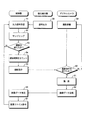
図3は,制御器30,磁化検出器10(検出コイル16),およびデジタルカメラ21の動作の流れを示すフローチャートである。
FIG. 3 is a flowchart showing the operation flow of the
ワイヤロープ1は一般に複数本のストランドを撚り合わせてつくられており,その表面にらせん状の凹凸が存在するので,構造上,その断面積が長手方向に一定ではない。このため磁化検出器10(検出コイル16)からは常に出力信号(電圧信号)が出力される。磁化検出器10からの出力信号は,上述したように信号線を通じて制御器30に与えられる(ステップ58,51)。
The
制御器30において受信された磁化検出器10からの出力信号は,制御器30において所定時間間隔ごとにたとえば1ミリ秒ごとにサンプリングされ,サンプリング値(電圧値を表すデジタルデータ)がメモリに記録される(ステップ52)。一般には磁化検出器10からの出力信号は,制御器30においてあらかじめ設定されるゲインを用いて増幅され,増幅後の出力信号がサンプリングされる。
The output signal from the
制御器30は,メモリに記録された電圧値(サンプリング値)のそれぞれを,あらかじめ定められる閾値と比較する(ステップ53)。閾値以下であれば,制御器30は特段の処理を実行しない(ステップ53でNO)。
The
ワイヤロープ1に生じている損傷の程度が大きければ大きいほど,磁化検出器10からは大きな出力信号(電圧値)が出力される。また,ワイヤロープ1に損傷は発生していないものの,ワイヤロープ1の表面にゴミが付着している,たとえばワイヤロープ1やワイヤロープ1がかけられるシーブからの鉄粉がワイヤロープ1の表面に堆積していると,この場合にも上述した磁気回路における磁気抵抗が変動し,磁化検出器10から出力される出力信号は変動する。閾値を超える電圧値が検知された場合,制御器30は,その検知タイミングから所定の遅延時間(以下に詳述する)をカウントし,遅延時間を経過したタイミングに,デジタルカメラ21に駆動信号(撮影指示信号)を送信する(ステップ53でYES ,ステップ54,55)。
The greater the degree of damage occurring in the
デジタルカメラ21は制御器30からの撮影指示を常時待機しており(ステップ59,ステップ60でNO),制御器30からの撮影指示信号を受信したタイミングで撮影を実行する(ステップ60でYES ,ステップ61)。撮影によって取得されたワイヤロープ1の一部分を表す画像データは,信号線を通じてデジタルカメラ21から制御器30に送信される(ステップ62)。
The
制御器30は,デジタルカメラ21から送信された画像データを受信すると,受信した画像データをメモリに記録(保存)する(ステップ56,57)。画像データは任意のファイル形式(jpeg,gif,rawなど)でメモリに記録することができる。
When the
メモリに記憶される画像ファイルのそれぞれには,撮影順番を特定するデータを付随させることができる。たとえば,制御器30の計時機能を利用してメモリに記録される画像ファイルのファイル名に撮影時刻を含ませることで撮影順番を特定するデータを付随してもよいし,連続する番号をメモリに記録される画像ファイルのファイル名に含ませてもよい。画像ファイルのファイル名に代えて画像ファイルのヘッダ情報中に撮影順番を特定するデータを記録してもよい。
Data that specifies the shooting order can be attached to each of the image files stored in the memory. For example, data that specifies the shooting order may be attached by including the shooting time in the file name of the image file recorded in the memory by using the timing function of the
もっとも,メモリに記録される画像ファイルの記録順番を用いることでも,メモリに記憶される画像ファイルの撮影順番を特定することは可能である。たとえば先入れ先出し(FIFO)構造を保持するように画像ファイルのそれぞれをメモリに記録すればよい。 However, it is also possible to specify the shooting order of the image files stored in the memory by using the recording order of the image files recorded in the memory. For example, each image file may be recorded in memory to retain a first-in first-out (FIFO) structure.
上述した遅延時間について図2を参照して説明する。 The delay time described above will be described with reference to FIG.
図2に示すように,ロープテスタでは,ワイヤロープ1が移動する方向を基準にして,ワイヤロープ1の移動方向の先方に画像撮影ユニット20が設けられ,後方に磁化検出器10が設けられている。固定的に設置されたロープテスタ・システムを用いて移動するワイヤロープ1が連続的に検査されるので,ワイヤロープ1の欠陥箇所は,はじめに検出コイル16を通過し,次にデジタルカメラ21の設置箇所を通過することになる。
As shown in FIG. 2, in the rope tester, the
ワイヤロープ1の移動速度をy(m/min),検出コイル16とデジタルカメラ21の間の距離をx(mm)とする。ワイヤロープ1の欠陥箇所が移動する速度はワイヤロープ1の移動速度と等しいので,欠陥箇所の移動速度は,単位をmm/sとすれば次式によって表される。
The moving speed of the
y(m/min)=1000/60・y(mm/s)・・・式1
y (m / min) = 1000/60 ・ y (mm / s) ・ ・ ・
ワイヤロープ1の欠陥箇所が検出コイル16を通過してt(s)後にデジタルカメラ21の直上に移動するとすれば,次式が成り立つ。
Assuming that the defective portion of the
1000/60・y・t=x
t=(x/y)・(60/1000)・・・式2
1000/60 ・ y ・ t = x
t = (x / y) ・ (60/1000) ・ ・ ・
たとえば,検出コイル16とデジタルカメラ21の間の距離x=100mm,ワイヤロープ1の移動速度y=16(m/min)とすると,以下の値が算出される。
For example, assuming that the distance between the
t=(100/16)・(60/1000)=0.375(s) t = (100/16) ・ (60/1000) = 0.375 (s)
すなわち,ワイヤロープ1の欠陥箇所が検出コイル16を通った後, 0.375(s)後に,その欠陥箇所はデジタルカメラ21が設置されている位置に到達する。制御器30は,設定されるワイヤロープ1の移動速度yおよび検出コイル16とデジタルカメラ21の間の距離xを用いて上述した遅延時間を算出する(あらかじめ算出してメモリに記録する)。算出された遅延時間がデジタルカメラ21に駆動信号を送信するタイミング制御に用いられる。たとえば制御器30が備えるCPUのクロック信号を用いることで,制御器30は,欠陥検出(閾値を超える出力信号の検出)から所定の遅延時間の経過後にデジタルカメラ21に駆動信号を出力することができる。
That is, 0.375 (s) after the defective portion of the
図4は,コンピュータ装置40の表示装置の画面を示すもので,コンピュータ装置40にインストールされている解析プログラムによって表示される画面例を示している。
FIG. 4 shows the screen of the display device of the
制御器30のメモリに記録された所定時間ごとの磁化検出器10(検出コイル16)からの出力信号(電圧値),およびデジタルカメラ21によって撮影されたワイヤロープ1を表す画像データを含む画像ファイルは,信号線を通じてまたは可搬のメモリカードを介して,コンピュータ装置40に与えられる。ワイヤロープ1を検査したときの測定日時,ワイヤロープ1の移動速度(ロープスピード),ロープ径,ゲイン設定値,および判定レベル(閾値)を表すデータも,信号線を通じてまたは可搬のメモリカードを介して,コンピュータ装置40に与えられる。
An image file containing an output signal (voltage value) from the magnetization detector 10 (detection coil 16) at predetermined time intervals recorded in the memory of the
コンピュータ装置40において解析プログラムが起動されると,図4に示す解析ウインドウ70がコンピュータ装置40の表示装置の表示画面上に表示される。
When the analysis program is started in the
解析ウインドウ70の右側に,測定日時表示欄74a,ロープスピード表示欄74b,ロープ径表示欄74c,ゲイン設定値表示欄74d,および判定レベル表示欄74eが設けられている。初期状態においては,これらの表示欄74a〜74eには制御器30に設定された設定値が表示される。
On the right side of the
解析ウインドウ70の左側には,横軸をワイヤロープ1の位置(m),縦軸を電圧値(V)とする2つの出力信号グラフ表示欄71,72が上下二段に表示される。
On the left side of the
出力信号グラフ表示欄71,72には,上述した磁化検出器10(検出コイル16)から出力される出力信号(電圧値)を表すグラフが,縦向きの直線の長さによって示される。上述したように,磁化検出器10からの出力信号は所定時間間隔ごとたとえば1ミリ秒ごとに順番(時系列)にサンプリングされる。またワイヤロープ1の移動速度(ロープスピード)は既知である。したがって,サンプリングされた多数の出力信号(多数の電圧値)のそれぞれを,ワイヤロープ1の位置(検査開始位置を 0.0mとしたときの検査開始位置からの距離)と対応づけることができ,これによって横軸をワイヤロープ1の位置(m),縦軸を電圧値(v)とする出力信号グラフが,解析プログラムによって作成される。
In the output signal
上段の出力信号グラフ表示欄71には,ワイヤロープ1の全検査長にわたる出力信号がグラフ表示される。図4に示す例ではワイヤロープ1の全検査長が150.8mであり,上段の出力信号グラフ表示欄71の横軸には,検査開始位置(0.0m)から全検査長である150.8mまでの範囲が示されている。他方,下段の出力信号グラフ表示欄72は,上段の出力信号グラフ表示欄71の横軸の一部の範囲を拡大して示すもので,上段の出力信号グラフ表示欄71の下方に表示される矩形のスライダ78を,入力装置(マウス等)を用いて左右に動かすことによって拡大範囲を選択することができる。拡大率(拡大幅)は可変であり,解析ウインドウ70の下方の中央部分に表示される拡大率入力欄77に拡大率が入力される。拡大率の大きさに応じて矩形のスライダ78の横幅が伸縮する。
In the output signal
出力信号グラフ表示欄71,72にはまた,閾値(判定レベル)を示す線73が,色を異ならせて(たとえば赤色で)表示され,この閾値線73を超える電圧値の出力信号を表すグラフの先端がマークされる(たとえば赤色の丸印がグラフ先端に示される)。
In the output signal
解析ウインドウ70の右側に設けられている判定ボタン75がクリックされると,閾値を越える電圧値の出力信号が検出されたワイヤロープ1の位置,すなわち欠陥位置が,リスト表示欄76に一覧に表示される。リスト表示欄76には,検出された欠陥箇所ごとに,連続する番号と,検査開始位置からの距離と,一つ前の欠陥箇所からの距離とが表示される。
When the
出力信号グラフ表示欄71,72にはさらに,閾値線73を越える電圧値の出力信号を表すグラフのそれぞれに対応するサムネイル画像80が表示される。このサムネイル画像80が,閾値を超える出力信号が検出されたときにデジタルカメラ21によって撮影されたワイヤロープ1の一部の画像である。デジタルカメラ21から出力される画像データからサムネイル画像80を表す画像データを作成する処理はコンピュータ装置40(解析プログラム)によって行われる。もちろん,デジタルカメラ21または制御器30においてサムネイル画像データを作成してもよい。
In the output signal
ワイヤロープ1はその検査開始位置から検査終了位置に向けて検査されるので,出力信号グラフ表示欄71,72に表示される多数の出力信号のグラフは,左から右に時系列に並べられたものである。また,上述したように,デジタルカメラ21によってワイヤロープ1が撮影されるのは,磁化検出器10(検出コイル16)からの出力信号に基づいて欠陥が検出された(閾値を超える電圧値が検出された)ときであり,さらに画像ファイルのそれぞれは上述したようにその撮影順番を特定するデータを含む。したがって,閾値を超える出力信号のグラフのそれぞれについて,左から右に並ぶ順番に,画像ファイルをその撮影順番の古いものから対応づけることで,閾値線73を越える電圧値の出力信号を表すグラフのそれぞれと,その電圧値の出力信号が検出された欠陥箇所のワイヤロープ1の画像80とを,正確に対応づけることができる。
Since the
サムネイル画像80がクリックされたときに,クリックされたサムネイル画像80の作成に用いられたオリジナルの画像データに基づく画像を表示画面に表示してもよい(拡大表示)。これによって,欠陥箇所の外観を,表示画面上で詳細に確認することができる。また,欠陥が損傷によるものであるか,または異物付着によるものであるかも確実に判定することができる。さらに,磁化検出器10を用いた検査結果(グラフ表示)に加えて欠陥箇所の外観画像を確認することができるので,磁化検出器10のみを用いた場合には把握しにくいたとえば断線間隔,断線本数といった,より具体的なワイヤロープ1の状況を詳細に確認することができる。これによって,現場において欠陥箇所を探すワイヤロープ1の範囲,または現場で慎重に検査すべきワイヤロープ1の範囲を大幅に狭めることができ,効率のよい現場検査を実現することができ,現場検査における欠陥の見落としも大幅に少なくすることができる。
When the
解析ウインドウ70の右側の判定レベル表示欄74eに表示される閾値を表す数値は,別の数値に代えることができる。より大きな数値を判定レベル表示欄74eに入力すると,出力信号グラフ表示欄71,72の閾値線73が上方に移動する。新たに入力された閾値を超える電圧値の出力信号を表すグラフの先端がマークされ,かつサムネイル画像80が対応づけられて表示されるので,表示されるサムネイル画像80の数は少なくなる。欠陥の程度が大きいと考えられる箇所のサムネイル画像80のみを,出力信号グラフ表示欄71,72に表示させることができる。
The numerical value indicating the threshold value displayed in the judgment
判定レベル表示欄74eの数値(閾値)をより小さい数値に代えることもできる。閾値を小さくすることによってはじめて閾値を超えることになった出力信号を表すグラフについては,撮影が行われていないので,サムネイル画像80を対応づけて表示することができないのは言うまでもない。もっとも,制御器30において設定される閾値を小さい値に設定しておくことで,より多くの箇所のワイヤロープ1が撮影されることになるのは言うまでもない。
The numerical value (threshold value) in the determination
上述した実施例では1本のワイヤロープ1を検査するためのロープテスタを示したが,磁化検出器10および画像撮影ユニット20を並列に複数並べることで,複数本のワイヤロープ1を同時に検査することもできる。この場合には,解析ウインドウ70には,複数本のワイヤロープ1のそれぞれについての出力信号グラフ表示欄71,72が表示される(ワイヤロープ1ごとの解析ウインドウ70が作成される)。
In the above-described embodiment, a rope tester for inspecting one
また上述した実施例では,1つのデジタルカメラ21を用いてワイヤロープ1を一方向から撮影する構成を示したが,複数のデジタルカメラ21を用いてワイヤロープ1の同一箇所を異なる方向から撮影してもよい。ワイヤロープ1の周方向のより広い範囲,または周方向の全範囲を,画像確認することができる。
Further, in the above-described embodiment, the configuration in which the
1 ワイヤロープ
10 磁化検出器
20 撮影ユニット
21 デジタルカメラ(撮影装置)
30 制御器
31 入力装置(入力部)
40 コンピュータ装置(ワイヤロープ解析装置)
1 wire rope
10 Magnetization detector
20 shooting unit
21 Digital camera (shooting device)
30 controller
31 Input device (input unit)
40 Computer equipment (wire rope analyzer)
Claims (5)
横軸をワイヤロープ位置,縦軸を磁化検出器から出力される出力信号とするグラフを表示するグラフ表示手段,および
上記グラフ表示手段によって表示される磁化検出器からの出力信号を表すグラフのうち上記欠陥箇所を表すグラフに対応づけて,上記画像データによって表される一または複数のワイヤロープのサムネイル画像をグラフ上に表示するワイヤロープ画像表示手段を備えている,
ワイヤロープ解析装置。 A magnetization detector including a magnetizer that generates a magnetic force and a detector that detects a magnetic change generated from a wire rope that moves at a predetermined speed and is magnetized by the magnetic force generated by the magnetizer. An imaging device that is provided at a predetermined interval between the detector and the wire rope, and is connected to the magnetization detector and the photographing device, and outputs a signal output from the magnetization detector at a predetermined time interval. Each is provided with a first recording means for recording in the storage means in chronological order and a second recording means for recording the image data output from the photographing device in the storage means including the order of photographing by the magnetization detector. A wire rope including a controller that detects a defective portion of the wire rope based on the detected magnetic change and outputs a drive signal for driving the imaging device at the timing when the defective portion reaches the installation location of the imaging device. It is a wire rope analysis device to which the output signal from the magnetization detector recorded by the rope tester for inspecting and the image data from the photographing device are given.
Of the graph display means for displaying a graph in which the horizontal axis is the wire rope position and the vertical axis is the output signal output from the magnetization detector, and the graph showing the output signal from the magnetization detector displayed by the graph display means. A wire rope image display means for displaying a thumbnail image of one or more wire ropes represented by the image data on the graph in association with the graph showing the defect location is provided.
Wire rope analyzer.
上記入力部から受け付けられる移動速度と所定間隔を表す距離とを用いて,上記駆動信号を出力すべきタイミングを規定する遅延時間を算出する遅延時間算出手段を備えている,
請求項1に記載のワイヤロープ解析装置。 The controller receives an input of a predetermined moving speed of the wire rope and a distance representing a predetermined distance between the magnetization detector and the imaging device, and a moving speed and a predetermined interval received from the input unit. It is provided with a delay time calculation means for calculating the delay time that defines the timing at which the drive signal should be output using the distance representing the above.
The wire rope analyzer according to claim 1.
請求項1または2に記載のワイヤロープ解析装置。 The controller detects a defective portion of the wire rope when the output signal output from the magnetic detector exceeds the first threshold value.
The wire rope analyzer according to claim 1 or 2.
上記ワイヤロープ画像表示手段は,上記第2の閾値を超える出力信号を表すグラフに対応づけて,上記磁化検出器から出力される出力信号が上記第2の閾値を超えることで撮影された画像データによって表されるワイヤロープ画像を表示する,
請求項3に記載のワイヤロープ解析装置。 Further provided are a threshold value display means for displaying a second threshold value equal to or higher than the first threshold value in the graph, and a threshold value input means for inputting the second threshold value.
The wire rope image display means corresponds to a graph representing an output signal exceeding the second threshold value, and image data captured when the output signal output from the magnetization detector exceeds the second threshold value. Display the wire rope image represented by,
The wire rope analysis apparatus according to claim 3.
横軸をワイヤロープ位置,縦軸を磁化検出器から出力される出力信号とするグラフを表示装置に表示し,
表示される磁化検出器からの出力信号を表すグラフのうち上記欠陥箇所を表すグラフに対応づけて,上記画像データによって表される一または複数のワイヤロープのサムネイル画像をグラフ上に表示するように,上記ワイヤロープ解析装置を制御する,
ワイヤロープ解析装置を制御するプログラム。 A magnetizer that generates a magnetic force, and a magnetization detector that includes a detector that detects a magnetic change generated from a wire rope that moves at a predetermined speed and is magnetized by the magnetic force generated by the magnetizer. An imaging device that is provided at a predetermined interval between the detector and the wire rope, and is connected to the magnetization detector and the imaging device, and outputs a signal output from the magnetization detector at a predetermined time interval. A first recording means for recording in the storage means in chronological order for each, and a second recording means for recording the image data output from the photographing device in the storage means including the order of photographing are provided by the magnetization detector. A wire rope including a controller that detects a defective portion of the wire rope based on the detected magnetic change and outputs a drive signal for driving the imaging device at a timing when the defective portion reaches the installation location of the imaging device. A program that controls a wire rope analyzer that is given an output signal from the magnetization detector and image data from the imaging device recorded by a rope tester for inspecting.
A graph with the horizontal axis as the wire rope position and the vertical axis as the output signal output from the magnetization detector is displayed on the display device.
Among the graphs representing the output signals from the displayed magnetization detector, the thumbnail images of one or more wire ropes represented by the above image data are displayed on the graph in association with the graph showing the above-mentioned defective portion. , Control the above wire rope analyzer ,
A program that controls a wire rope analyzer.
Priority Applications (6)
| Application Number | Priority Date | Filing Date | Title |
|---|---|---|---|
| JP2017237676A JP6956616B2 (en) | 2017-12-12 | 2017-12-12 | Rope tester, wire rope analyzer and its control program |
| SG11202005244QA SG11202005244QA (en) | 2017-12-12 | 2018-12-10 | Rope tester, wire rope analyzing apparatus and control program therefor |
| CN201880079372.4A CN111512147A (en) | 2017-12-12 | 2018-12-10 | Rope testing machine, metal cord analysis device, and control program therefor |
| EP18888688.1A EP3726204B1 (en) | 2017-12-12 | 2018-12-10 | Rope tester, wire rope analyzing apparatus and control program thereof |
| PCT/JP2018/045293 WO2019117079A1 (en) | 2017-12-12 | 2018-12-10 | Rope tester, wire rope analysis device and control program thereof |
| US16/896,782 US11543386B2 (en) | 2017-12-12 | 2020-06-09 | Rope tester, wire rope analyzing apparatus and control program therefor |
Applications Claiming Priority (1)
| Application Number | Priority Date | Filing Date | Title |
|---|---|---|---|
| JP2017237676A JP6956616B2 (en) | 2017-12-12 | 2017-12-12 | Rope tester, wire rope analyzer and its control program |
Publications (3)
| Publication Number | Publication Date |
|---|---|
| JP2019105507A JP2019105507A (en) | 2019-06-27 |
| JP2019105507A5 JP2019105507A5 (en) | 2020-12-17 |
| JP6956616B2 true JP6956616B2 (en) | 2021-11-02 |
Family
ID=66820339
Family Applications (1)
| Application Number | Title | Priority Date | Filing Date |
|---|---|---|---|
| JP2017237676A Active JP6956616B2 (en) | 2017-12-12 | 2017-12-12 | Rope tester, wire rope analyzer and its control program |
Country Status (6)
| Country | Link |
|---|---|
| US (1) | US11543386B2 (en) |
| EP (1) | EP3726204B1 (en) |
| JP (1) | JP6956616B2 (en) |
| CN (1) | CN111512147A (en) |
| SG (1) | SG11202005244QA (en) |
| WO (1) | WO2019117079A1 (en) |
Families Citing this family (4)
| Publication number | Priority date | Publication date | Assignee | Title |
|---|---|---|---|---|
| JP7187855B2 (en) * | 2018-07-11 | 2022-12-13 | 株式会社島津製作所 | Magnetic material inspection system, magnetic material inspection apparatus, and magnetic material inspection method |
| US11506632B2 (en) * | 2020-10-20 | 2022-11-22 | Obshchestvo s ogranichennoi otvetstvennostiu “INTRON PLIUS” | Method for predicting a residual operating life of a steel rope |
| US11480546B2 (en) | 2020-12-23 | 2022-10-25 | Shimadzu Corporation | Magnetic material inspection system, magnetic material inspection device, and magnetic material inspection method |
| CN113820274B (en) * | 2021-08-20 | 2023-06-27 | 中国电子科技集团公司第三十八研究所 | Movable hawser quality testing integrated device |
Family Cites Families (11)
| Publication number | Priority date | Publication date | Assignee | Title |
|---|---|---|---|---|
| JPH11230946A (en) * | 1998-02-10 | 1999-08-27 | Hitachi Building Systems Co Ltd | Magnetic flaw-detecting device of wire rope |
| JP3547342B2 (en) * | 1999-07-30 | 2004-07-28 | 株式会社日立ビルシステム | Magnetic flaw detector for wire rope |
| HK1122096A1 (en) * | 2006-04-04 | 2009-05-08 | Micro Motion Inc | Diagnostic apparatus and methods for a coriolis flow meter |
| JP2009012903A (en) | 2007-07-03 | 2009-01-22 | Mitsubishi Electric Building Techno Service Co Ltd | Device and method for inspecting component strand disconnection of elevator wire rope |
| JP5003351B2 (en) * | 2007-08-23 | 2012-08-15 | Jfeスチール株式会社 | Quality inspection method and apparatus for minute surface defects in magnetic metal strip |
| JP3156764U (en) * | 2009-10-30 | 2010-01-14 | 住友金属工業株式会社 | Surface flaw inspection device |
| JP5428798B2 (en) * | 2009-11-20 | 2014-02-26 | 株式会社明電舎 | Wire rope inspection device |
| WO2013145823A1 (en) * | 2012-03-28 | 2013-10-03 | 三菱電機株式会社 | Wire rope inspection device |
| CN104515777B (en) * | 2015-01-14 | 2017-03-08 | 兖州煤业股份有限公司 | The strong magnetic image joint online nondestructive inspection system of steel wire rope and method |
| CN105293242B (en) * | 2015-11-25 | 2018-07-17 | 佛山住友富士电梯有限公司 | A kind of elevator rope detection device |
| CN106018544B (en) * | 2016-06-24 | 2018-03-20 | 窦柏林 | A kind of steel wire rope Holographic test system |
-
2017
- 2017-12-12 JP JP2017237676A patent/JP6956616B2/en active Active
-
2018
- 2018-12-10 EP EP18888688.1A patent/EP3726204B1/en active Active
- 2018-12-10 SG SG11202005244QA patent/SG11202005244QA/en unknown
- 2018-12-10 WO PCT/JP2018/045293 patent/WO2019117079A1/en unknown
- 2018-12-10 CN CN201880079372.4A patent/CN111512147A/en active Pending
-
2020
- 2020-06-09 US US16/896,782 patent/US11543386B2/en active Active
Also Published As
| Publication number | Publication date |
|---|---|
| JP2019105507A (en) | 2019-06-27 |
| EP3726204A4 (en) | 2021-08-25 |
| EP3726204B1 (en) | 2023-11-29 |
| US20200300811A1 (en) | 2020-09-24 |
| US11543386B2 (en) | 2023-01-03 |
| SG11202005244QA (en) | 2020-07-29 |
| WO2019117079A1 (en) | 2019-06-20 |
| EP3726204C0 (en) | 2023-11-29 |
| EP3726204A1 (en) | 2020-10-21 |
| CN111512147A (en) | 2020-08-07 |
Similar Documents
| Publication | Publication Date | Title |
|---|---|---|
| JP6956616B2 (en) | Rope tester, wire rope analyzer and its control program | |
| US20150062328A1 (en) | Camera Based Cable Inspection System | |
| JP2009512879A (en) | Method and apparatus for inspecting running strands | |
| JP2004526179A5 (en) | ||
| JP5428798B2 (en) | Wire rope inspection device | |
| KR101187908B1 (en) | Integrated surveillance system diplaying a plural of event images and method using the same | |
| KR20140123593A (en) | Wire rope inspection device | |
| JP2019105507A5 (en) | ||
| JP6715282B2 (en) | Quality monitoring system | |
| JP5032072B2 (en) | Monitoring device | |
| JP5158993B2 (en) | Residual oxide detection and classification device in metal plate production line | |
| JP5418635B2 (en) | Worker safety inspection device | |
| JP2009237648A (en) | Operator safety testing apparatus | |
| JP4513722B2 (en) | Monitoring control apparatus and monitoring control method | |
| JP4133691B2 (en) | Road monitoring system | |
| JP7115651B2 (en) | Elevator diagnostic equipment and diagnostic analysis equipment | |
| JP3605579B2 (en) | Dust detector, dust detection system, particle detector and dust detection method for clean room | |
| JPH0360312A (en) | Image processor for inspection of overhead line | |
| JP2001201445A (en) | Displacement measuring apparatus | |
| JPH0360313A (en) | Image processor for inspection of overhead line | |
| JP3209310B2 (en) | Length measurement method for long objects | |
| JP2021145303A5 (en) | ||
| JP2021152482A (en) | Image processing device, image processing method, and program | |
| JP2002022483A (en) | Navigation system test evaluating device | |
| JP2005063303A (en) | Method for measuring number of passing object |
Legal Events
| Date | Code | Title | Description |
|---|---|---|---|
| A521 | Request for written amendment filed |
Free format text: JAPANESE INTERMEDIATE CODE: A523 Effective date: 20201029 |
|
| A621 | Written request for application examination |
Free format text: JAPANESE INTERMEDIATE CODE: A621 Effective date: 20201029 |
|
| A131 | Notification of reasons for refusal |
Free format text: JAPANESE INTERMEDIATE CODE: A131 Effective date: 20210406 |
|
| A521 | Request for written amendment filed |
Free format text: JAPANESE INTERMEDIATE CODE: A523 Effective date: 20210507 |
|
| TRDD | Decision of grant or rejection written | ||
| A01 | Written decision to grant a patent or to grant a registration (utility model) |
Free format text: JAPANESE INTERMEDIATE CODE: A01 Effective date: 20210921 |
|
| A61 | First payment of annual fees (during grant procedure) |
Free format text: JAPANESE INTERMEDIATE CODE: A61 Effective date: 20211005 |
|
| R150 | Certificate of patent or registration of utility model |
Ref document number: 6956616 Country of ref document: JP Free format text: JAPANESE INTERMEDIATE CODE: R150 |