JP6956367B2 - Lighting device - Google Patents

Lighting device Download PDF

Info

Publication number
JP6956367B2
JP6956367B2 JP2018034072A JP2018034072A JP6956367B2 JP 6956367 B2 JP6956367 B2 JP 6956367B2 JP 2018034072 A JP2018034072 A JP 2018034072A JP 2018034072 A JP2018034072 A JP 2018034072A JP 6956367 B2 JP6956367 B2 JP 6956367B2
Authority
JP
Japan
Prior art keywords
main body
installation
lighting device
shaft portion
holding member
Prior art date
Legal status (The legal status is an assumption and is not a legal conclusion. Google has not performed a legal analysis and makes no representation as to the accuracy of the status listed.)
Active
Application number
JP2018034072A
Other languages
Japanese (ja)
Other versions
JP2019149316A (en
Inventor
和英 高武
Current Assignee (The listed assignees may be inaccurate. Google has not performed a legal analysis and makes no representation or warranty as to the accuracy of the list.)
Panasonic Intellectual Property Management Co Ltd
Original Assignee
Panasonic Intellectual Property Management Co Ltd
Priority date (The priority date is an assumption and is not a legal conclusion. Google has not performed a legal analysis and makes no representation as to the accuracy of the date listed.)
Filing date
Publication date
Application filed by Panasonic Intellectual Property Management Co Ltd filed Critical Panasonic Intellectual Property Management Co Ltd
Priority to JP2018034072A priority Critical patent/JP6956367B2/en
Publication of JP2019149316A publication Critical patent/JP2019149316A/en
Application granted granted Critical
Publication of JP6956367B2 publication Critical patent/JP6956367B2/en
Active legal-status Critical Current
Anticipated expiration legal-status Critical

Links

Images

Landscapes

  • Non-Portable Lighting Devices Or Systems Thereof (AREA)

Description

本開示は、照明装置に関する。 The present disclosure relates to a lighting device.

従来、照明装置として、光源部を有する本体部と、本体部を設置台に設置する設置部材と、を備えるものが知られている(例えば、特許文献1参照)。 Conventionally, as a lighting device, a main body portion having a light source portion and an installation member for installing the main body portion on an installation stand are known (see, for example, Patent Document 1).

この特許文献1には、道路の側部に設けられた高欄の上面に設置され、道路の路面を照射することで、夜間等における車両の走行を支援する低位置照明装置が開示されている。 Patent Document 1 discloses a low-position lighting device that is installed on the upper surface of a balustrade provided on a side of a road and irradiates the road surface to support the traveling of a vehicle at night or the like.

特開2017−134620号公報JP-A-2017-134620

このように、高欄等の設置台に設置部材を介して本体部を設置する場合、設置部材による設置台への設置が解除された際に、本体部が落下してしまうのを抑制できるようにするのが好ましい。 In this way, when the main body is installed on an installation stand such as a balustrade via an installation member, it is possible to prevent the main body from falling when the installation on the installation stand by the installation member is released. It is preferable to do.

そして、本体部の落下を抑制できるようにするためには、ワイヤの一端を設置台に固定し、他端を本体部に固定することで、設置部材による設置が解除された際に、本体部がワイヤによって吊り下げられるようにすることが考えられる。 Then, in order to prevent the main body from falling, one end of the wire is fixed to the installation base and the other end is fixed to the main body, so that when the installation by the installation member is released, the main body is released. Is conceivable to be suspended by a wire.

しかしながら、ワイヤを用いて本体部の落下を抑制できるようにすると、通常の設置状態においては、撓んだワイヤが本体部からはみ出してしまう等により見栄えが悪化してしまうおそれがある。 However, if the main body can be suppressed from falling by using a wire, the appearance may be deteriorated due to the bent wire protruding from the main body in a normal installation state.

そこで、本開示は、落下を抑制しつつ、見栄えをより向上させることのできる照明装置を得ることを目的とする。 Therefore, an object of the present disclosure is to obtain a lighting device capable of further improving the appearance while suppressing the fall.

本開示にかかる照明装置は、光源部を有する本体部と、前記本体部を設置台に設置する設置部材と、前記本体部の落下を抑制する落下抑制部材と、を備えている。また、前記落下抑制部材は、前記本体部に取り付けられる本体部側取付部と、前記設置台に取り付けられる設置台側取付部と、前記本体部側取付部と前記設置台側取付部とを相対回動可能に保持する保持部材と、を備えている。 The lighting device according to the present disclosure includes a main body portion having a light source portion, an installation member for installing the main body portion on an installation table, and a fall suppression member for suppressing the fall of the main body portion. Further, the fall suppressing member is such that the main body side mounting portion attached to the main body portion, the installation base side mounting portion attached to the installation base, and the main body side mounting portion and the installation base side mounting portion are relative to each other. It includes a holding member that rotatably holds the member.

本開示によれば、落下を抑制しつつ、見栄えをより向上させることのできる照明装置を得ることができる。 According to the present disclosure, it is possible to obtain a lighting device capable of further improving the appearance while suppressing the fall.

一実施形態にかかる照明装置を道路に設置した状態を模式的に示す斜視図である。It is a perspective view which shows typically the state which the lighting device which concerns on one Embodiment is installed on the road. 一実施形態にかかる照明装置を模式的に示す斜視図である。It is a perspective view which shows typically the lighting apparatus which concerns on one Embodiment. 一実施形態にかかる照明装置を示す図であって、(a)は平面図、(b)は正面図である。It is a figure which shows the lighting apparatus which concerns on one Embodiment, (a) is a plan view, (b) is a front view. 一実施形態にかかる照明装置の断面図である。It is sectional drawing of the lighting apparatus which concerns on one Embodiment. 一実施形態にかかる照明装置の回動状態を模式的に示す側面図である。It is a side view which shows typically the rotating state of the lighting apparatus which concerns on one Embodiment. 一実施形態にかかる落下抑制部材を示す正面図である。It is a front view which shows the fall suppression member which concerns on one Embodiment. 一実施形態にかかる落下抑制部材を示す分解斜視図である。It is an exploded perspective view which shows the drop suppression member which concerns on one Embodiment. 一実施形態にかかる落下抑制部材の機能を説明する図である。It is a figure explaining the function of the fall suppression member which concerns on one Embodiment. 一実施形態にかかる照明装置の落下距離を説明する図であって、(a)は照明装置全体を示す図、(b)は落下抑制部材を示す図である。It is a figure explaining the fall distance of the lighting device which concerns on one Embodiment, (a) is a figure which shows the whole lighting device, (b) is a figure which shows the fall suppression member. 第1変形例にかかる保持部材を示す分解斜視図である。It is an exploded perspective view which shows the holding member which concerns on the 1st modification. 第2変形例にかかる保持部材を示す分解斜視図である。It is an exploded perspective view which shows the holding member which concerns on the 2nd modification. 第3変形例にかかる落下抑制部材を示す分解斜視図である。It is an exploded perspective view which shows the drop | fall suppressing member concerning the 3rd modification.

以下、本開示にかかる照明装置について、図面を参照しながら詳細に説明する。なお、以下では、照明装置として、道路の側部に設けられた高欄の上面等に設置される低位置照明装置を例示するとともに、光源としてLED光源を用いたものを例示する。 Hereinafter, the lighting device according to the present disclosure will be described in detail with reference to the drawings. In the following, as the lighting device, a low-position lighting device installed on the upper surface of a balustrade provided on the side of the road or the like will be illustrated, and an LED light source will be used as the light source.

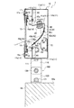
本実施形態にかかる照明装置1は、図1に示すように、道路80の側部に設けられた高欄(設置台)82の上面(設置面)82aに設置されており、道路80の路面81を照射することで、夜間等における車両90の走行を支援するものである。 As shown in FIG. 1, the lighting device 1 according to the present embodiment is installed on the upper surface (installation surface) 82a of the balustrade (installation table) 82 provided on the side of the road 80, and is installed on the road surface 81 of the road 80. By irradiating the vehicle 90, the vehicle 90 is supported to travel at night or the like.

なお、図1には、道路80として、4つの車線81aを有する4車線(片側2車線)の自動車専用道路(高速道路等)を例示している。 Note that FIG. 1 illustrates an automobile-only road (expressway, etc.) having four lanes (two lanes on each side) having four lanes 81a as the road 80.

道路80の路面81は、図1に示すように、車両90が走行する帯状の車線81aと、端側の車線81の側方に設けられた路肩81bと、車線81aを往復方向別に分離する中央帯81cと、で構成されている。 As shown in FIG. 1, the road surface 81 of the road 80 is a center that separates the strip-shaped lane 81a on which the vehicle 90 travels, the road shoulder 81b provided on the side of the lane 81 on the end side, and the lane 81a according to the reciprocating direction. It is composed of a band 81c.

図1では、端側(図1の左側)の車線81aと路肩81bとを左側の白線実線により区画しており、中央側(図1の右側)の車線81aと中央帯81cとを右側の白線実線により区画している。また、片側の2つの車線81a,81aを白線破線によって区画している。 In FIG. 1, the lane 81a on the end side (left side in FIG. 1) and the shoulder 81b are separated by a solid white line on the left side, and the lane 81a on the center side (right side in FIG. 1) and the median strip 81c are separated by a white line on the right side. It is divided by a solid line. Further, the two lanes 81a and 81a on one side are separated by a broken white line.

また、中央帯81cは、縁石81eが設けられた分離帯81dと、分離帯81dの両側に設けられた側帯81fと、を有しており、縁石81eには対向車線側の車両の進入等を抑制するガードレール81gが形成されている。 Further, the median strip 81c has a separation zone 81d provided with a curb 81e and side bands 81f provided on both sides of the separation zone 81d, and the curb 81e is used to allow vehicles on the oncoming lane to enter. 81 g of a guardrail to suppress is formed.

さらに、道路80の側部には、高欄82および遮音壁83が、道路80の延伸方向に沿って形成されている。高欄82は、例えば、コンクリートを用いて形成することができ、この高欄82によって、路肩81bの車線81a側とは反対側が区画されている。 Further, on the side of the road 80, a balustrade 82 and a sound insulation wall 83 are formed along the extending direction of the road 80. The balustrade 82 can be formed using, for example, concrete, and the balustrade 82 defines the side of the road shoulder 81b opposite to the lane 81a side.

そして、高欄82の上面82aには、複数の照明装置1が道路80の延伸方向に沿って略等間隔に配置されている。このとき、一列に配置された複数の照明装置1がケーブル(配線)61により互いに接続されており、このケーブル(配線)61を介して電力が各照明装置1に外部から供給されるようになっている。 A plurality of lighting devices 1 are arranged on the upper surface 82a of the balustrade 82 at substantially equal intervals along the extending direction of the road 80. At this time, a plurality of lighting devices 1 arranged in a row are connected to each other by a cable (wiring) 61, and electric power is supplied to each lighting device 1 from the outside via the cable (wiring) 61. ing.

本実施形態では、照明装置1は、水平方向に細長い略直方体状の本体部10を有しており、この本体部10の内部には、光源部21および反射部30が配置されている(図4参照)。そして、光源部21から出射した光L1は、反射部30にて反射されて、本体部10に形成された貫通穴(窓部)12を介して外部に照射されるようになっている。 In the present embodiment, the lighting device 1 has a substantially rectangular parallelepiped main body portion 10 elongated in the horizontal direction, and a light source portion 21 and a reflection portion 30 are arranged inside the main body portion 10 (FIG. 4). Then, the light L1 emitted from the light source unit 21 is reflected by the reflection unit 30 and is irradiated to the outside through the through hole (window portion) 12 formed in the main body portion 10.

したがって、本実施形態では、本体部10の長手方向を道路80の延伸方向に略一致させるとともに、貫通穴(窓部)12を道路80側に向けた状態で、各照明装置1を高欄82の上面82aに設置している。そして、各照明装置1の貫通穴(窓部)12を介して照射された光L1によって道路80の路面81が照射されるようにしている。 Therefore, in the present embodiment, each lighting device 1 is placed on the balustrade 82 in a state where the longitudinal direction of the main body 10 is substantially aligned with the extending direction of the road 80 and the through hole (window portion) 12 is directed toward the road 80. It is installed on the upper surface 82a. Then, the road surface 81 of the road 80 is irradiated by the light L1 emitted through the through hole (window portion) 12 of each lighting device 1.

このとき、各照明装置1は、道路80の路面81における片側の車線81a(各照明装置1と中央帯81cとの間に存在する2つの車線81a)の幅方向における全領域を照明できるような範囲に光L1を出射できるようにするのが好ましい。 At this time, each lighting device 1 can illuminate the entire area in the width direction of one lane 81a (two lanes 81a existing between each lighting device 1 and the median strip 81c) on the road surface 81 of the road 80. It is preferable to be able to emit light L1 in the range.

また、各照明装置1を、道路80を走行する小型車の平均的な運転手の目線の高さより低い高さ位置に設置するのが好ましい。目線の高さとしては、例えば、1.2mとすることができ、照明装置1の高さとしては、例えば、1.1m程度とすることができる。 Further, it is preferable to install each lighting device 1 at a height position lower than the height of the line of sight of an average driver of a small car traveling on the road 80. The height of the line of sight can be, for example, 1.2 m, and the height of the lighting device 1 can be, for example, about 1.1 m.

そして、路面81から各照明装置1の上面までの高さを、道路80を走行する小型車の平均的な運転手の目線の高さよりも低くした上で、光L1を水平よりも高く進行させないようにするのが好ましい。こうすれば、光L1が道路80を走行する車両90の運転手の目に到達してしまうのを抑制することができるようになる。 Then, the height from the road surface 81 to the upper surface of each lighting device 1 should be lower than the height of the line of sight of the average driver of a small car traveling on the road 80, and the light L1 should not travel higher than horizontal. It is preferable to set it to. In this way, it is possible to prevent the light L1 from reaching the driver's eyes of the vehicle 90 traveling on the road 80.

なお、図1に示す道路80の構造は一例に過ぎず、他の構造をした道路に照明装置1を設置することも可能である。また、高欄82の上面82aに照明装置1を設置させる必要はなく、照明装置1の設置場所は、道路の構造に応じて適宜決定することができる。 The structure of the road 80 shown in FIG. 1 is only an example, and the lighting device 1 can be installed on a road having another structure. Further, it is not necessary to install the lighting device 1 on the upper surface 82a of the balustrade 82, and the installation location of the lighting device 1 can be appropriately determined according to the structure of the road.

次に、本実施形態にかかる照明装置1の具体的な構成について、主として図2〜図5を用いて説明する。 Next, a specific configuration of the lighting device 1 according to the present embodiment will be described mainly with reference to FIGS. 2 to 5.

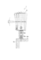
照明装置1は、図2に示すように、略直方体状をした本体部10と、本体部10を高欄82の上面82a等に設置するための設置部材50と、を備えている。 As shown in FIG. 2, the lighting device 1 includes a main body portion 10 having a substantially rectangular parallelepiped shape, and an installation member 50 for installing the main body portion 10 on the upper surface 82a or the like of the balustrade 82.

本体部10は、外郭を構成するハウジング11を有しており、このハウジング11は、例えば、アルミニウム等を含む金属材料を用いて形成することができる。 The main body 10 has a housing 11 that constitutes an outer shell, and the housing 11 can be formed by using, for example, a metal material including aluminum or the like.

本実施形態では、ハウジング11は、水平方向に細長い形状をしており、高欄82に設置した際に道路80側に配置される前壁11aと、水平方向に細長い形状をしており、高欄82に設置した際に道路80とは反対側に配置される後壁11bと、を備えている。また、前壁11aおよび後壁11bの長手方向の両側には、前壁11aと後壁11bとを連結する側壁11c,11cが、それぞれ設けられている。そして、前壁11aおよび後壁11bの上端には、前壁11aと後壁11bとを連結する天壁11dが設けられており、前壁11aおよび後壁11bの下端には、前壁11aと後壁11bとを連結する底壁11eが設けられている。 In the present embodiment, the housing 11 has an elongated shape in the horizontal direction, and has an elongated shape in the horizontal direction with the front wall 11a arranged on the road 80 side when installed on the balustrade 82. It is provided with a rear wall 11b, which is arranged on the opposite side of the road 80 when installed in. Further, on both sides of the front wall 11a and the rear wall 11b in the longitudinal direction, side walls 11c and 11c connecting the front wall 11a and the rear wall 11b are provided, respectively. A top wall 11d connecting the front wall 11a and the rear wall 11b is provided at the upper ends of the front wall 11a and the rear wall 11b, and a front wall 11a and the front wall 11a are provided at the lower ends of the front wall 11a and the rear wall 11b. A bottom wall 11e that connects the rear wall 11b is provided.

このように、ハウジング11は、長手方向を有する中空の直方体状に形成されており、道路80の延伸方向に沿う長さaと、道路80に対する水平方向の奥行きbと、高さcと、を有している。このハウジング11の各寸法は、例えば、長さaを1.3m、奥行きbを10cm、高さcを22cm程度とすることができる。 As described above, the housing 11 is formed in a hollow rectangular parallelepiped shape having a longitudinal direction, and has a length a along the extending direction of the road 80, a depth b in the horizontal direction with respect to the road 80, and a height c. Have. The dimensions of the housing 11 can be, for example, a length a of 1.3 m, a depth b of 10 cm, and a height c of about 22 cm.

そして、ハウジング11によって画成された本体部10の内部には、光源部21および反射部30が配置されている。さらに、本体部10の内部には、端子台71および電源部72等の電子部品が配置されている。 A light source unit 21 and a reflection unit 30 are arranged inside the main body portion 10 defined by the housing 11. Further, electronic components such as a terminal block 71 and a power supply portion 72 are arranged inside the main body portion 10.

また、ハウジング11の正面、すなわち、ハウジング11の前壁11aには、前後方向に貫通する貫通穴(窓部)12が形成されている。本実施形態では、この貫通穴(窓部)12は、水平方向に細長い長方形状をしており、輪郭形状が水平方向に細長い長方形の縁となる前壁11aの中央に形成されている。すなわち、ハウジング11の前壁11aの形状は、水平方向に細長い長方形の枠状をしている。 Further, a through hole (window portion) 12 penetrating in the front-rear direction is formed on the front surface of the housing 11, that is, on the front wall 11a of the housing 11. In the present embodiment, the through hole (window portion) 12 has a horizontally elongated rectangular shape, and is formed in the center of the front wall 11a whose contour shape is the edge of the horizontally elongated rectangular shape. That is, the shape of the front wall 11a of the housing 11 is a rectangular frame that is elongated in the horizontal direction.

さらに、本実施形態では、前壁11aに形成された貫通穴(窓部)12が、光源部21から出射した光L1を透過可能な透過板13によって閉塞されるようにしている。 Further, in the present embodiment, the through hole (window portion) 12 formed in the front wall 11a is blocked by the transmission plate 13 capable of transmitting the light L1 emitted from the light source portion 21.

透過板13は、透明な平板であり、貫通穴(窓部)12よりも一回り大きい長方形状をしている。この透過板13は、例えば、ガラス、樹脂材料等を用いて形成することができる。 The transmission plate 13 is a transparent flat plate and has a rectangular shape that is one size larger than the through hole (window portion) 12. The transmission plate 13 can be formed by using, for example, glass, a resin material, or the like.

そして、透過板13の周縁部を、前壁11aにおける貫通孔(窓部)12の周縁領域に外側(前側)から接触させることで、貫通穴(窓部)12が透過板13によって閉塞されるようにしている。 Then, by bringing the peripheral edge portion of the transmission plate 13 into contact with the peripheral edge region of the through hole (window portion) 12 in the front wall 11a from the outside (front side), the through hole (window portion) 12 is closed by the transmission plate 13. I am trying to do it.

さらに、透過板13は、ヒンジ17によってハウジング11に回動可能に取り付けられており、透過板13をハウジング11から取り外すことなく、貫通穴(窓部)12の開閉を行えるようにしている。 Further, the transmission plate 13 is rotatably attached to the housing 11 by a hinge 17 so that the through hole (window portion) 12 can be opened and closed without removing the transmission plate 13 from the housing 11.

本実施形態では、図3(b)に示すように、複数(本実施形態では3つ)のヒンジ17を用い、透過板13の上部をハウジング11の正面の上部(前壁11aの上部)に取り付けることで、透過板13をハウジング11に回動可能に取り付けている。このとき、各ヒンジ17は、一方がねじ17aによってハウジング11の前壁11aに固定され、他方がねじ17bによって透過板13の上部に固定されている。 In the present embodiment, as shown in FIG. 3B, a plurality of hinges 17 (three in the present embodiment) are used, and the upper part of the transmission plate 13 is placed on the upper part of the front surface of the housing 11 (the upper part of the front wall 11a). By attaching, the transmission plate 13 is rotatably attached to the housing 11. At this time, one of the hinges 17 is fixed to the front wall 11a of the housing 11 by the screw 17a, and the other is fixed to the upper part of the transmission plate 13 by the screw 17b.

かかる構成とすることで、透過板13をヒンジ17を中心として外側(前側)に回動させた際には、透過板13の下部が前方かつ上方に移動し、透過板13による貫通穴(窓部)12の閉塞が解除されて、貫通穴(窓部)12が開かれることとなる。 With this configuration, when the transmission plate 13 is rotated outward (front side) around the hinge 17, the lower portion of the transmission plate 13 moves forward and upward, and the through hole (window) formed by the transmission plate 13 is formed. The blockage of the portion) 12 is released, and the through hole (window portion) 12 is opened.

このように、本実施形態では、透過板13を、照明装置1の設置時の結線作業や照明装置1の保守管理等を行う際に、貫通穴(窓部)12を開閉するための蓋として機能させている。 As described above, in the present embodiment, the transmission plate 13 is used as a lid for opening and closing the through hole (window portion) 12 when the wiring work at the time of installing the lighting device 1 and the maintenance management of the lighting device 1 are performed. It's working.

また、本実施形態では、透過板13が貫通穴(窓部)12を閉塞した状態で、透過板13の下部を、複数(本実施形態では3つ)の固定板18によってハウジング11の正面の下部(前壁11aの下部)に固定している。具体的には、各固定板18の下部をねじ18aによってハウジング11の前壁11aの下部に固定し、各固定板18の上部をねじ18bによって透過板13の下部に固定することで、透過板13の下部をハウジング11の正面の下部に固定している。 Further, in the present embodiment, in a state where the transmission plate 13 closes the through hole (window portion) 12, the lower portion of the transmission plate 13 is formed on the front surface of the housing 11 by a plurality of (three in this embodiment) fixing plates 18. It is fixed to the lower part (lower part of the front wall 11a). Specifically, the lower part of each fixing plate 18 is fixed to the lower part of the front wall 11a of the housing 11 by the screw 18a, and the upper part of each fixing plate 18 is fixed to the lower part of the transparent plate 13 by the screw 18b. The lower part of 13 is fixed to the lower part of the front surface of the housing 11.

このように、貫通穴(窓部)12を閉塞した状態で、透過板13の下部をハウジング11の下部正面に固定することで、透過板13の意図せぬ回動(貫通穴12が開かれてしまうこと)を抑制できるようにしている。なお、ねじ18aを取り外し、各固定板18の下部と前壁11aの下部との固定を解除した状態で、透過板13を回動させれば、貫通穴(窓部)12を開くことができる。 By fixing the lower part of the transmission plate 13 to the front surface of the lower part of the housing 11 in the state where the through hole (window portion) 12 is closed in this way, the transmission plate 13 is unintentionally rotated (the through hole 12 is opened). It is possible to suppress the problem. The through hole (window portion) 12 can be opened by rotating the transmission plate 13 with the screw 18a removed and the lower portion of each fixing plate 18 and the lower portion of the front wall 11a released from being fixed. ..

また、前壁11aにおける貫通穴(窓部)12の周縁部には段部14が形成されており、この段部14には防塵用のパッキン15が形成されている。 Further, a step portion 14 is formed on the peripheral edge of the through hole (window portion) 12 in the front wall 11a, and a dustproof packing 15 is formed on the step portion 14.

また、透過板13には、光L1の透過を遮断する遮光部16が形成されている。本実施形態では、図4に示すように、上側遮光板16aを透過板13の上部に内側(後側)から取り付けるとともに、下側遮光板16bを透過板13の下部に内側(後側)から取り付けることで、遮光部16を形成している。上側遮光板16aおよび下側遮光板16bは、水平方向に延在する帯状をしており、例えば、アルミニウム等を含む金属材料の表面に黒ツヤ消し塗装を施すことで形成することができる。なお、上側遮光板16aはねじ16cによって、下側遮光板16bはねじ16dによって透過板13に取り付けられている。 Further, the transmission plate 13 is formed with a light-shielding portion 16 that blocks the transmission of light L1. In the present embodiment, as shown in FIG. 4, the upper light-shielding plate 16a is attached to the upper part of the transmission plate 13 from the inside (rear side), and the lower light-shielding plate 16b is attached to the lower part of the transmission plate 13 from the inside (rear side). By attaching, the light-shielding portion 16 is formed. The upper light-shielding plate 16a and the lower light-shielding plate 16b have a strip shape extending in the horizontal direction, and can be formed by, for example, applying a black matte coating to the surface of a metal material including aluminum or the like. The upper light-shielding plate 16a is attached to the transmission plate 13 by a screw 16c, and the lower light-shielding plate 16b is attached to the transmission plate 13 by a screw 16d.

そして、本実施形態では、上述した光源部21が、発光ダイオード(LED)ユニットとしてのランプ20に組み込まれている。 Then, in the present embodiment, the above-mentioned light source unit 21 is incorporated in the lamp 20 as a light emitting diode (LED) unit.

このようなランプ20としては、従来公知のものを用いることができる。本実施形態では、略四角柱状をしており、道路80の延伸方向に沿う長さと、奥行きと、高さと、を有するランプ20を例示している。このランプ20の各寸法は、例えば、長さを56cm、奥行きを3cm、高さを1.8cm程度とすることができる。 As such a lamp 20, a conventionally known lamp can be used. In the present embodiment, the lamp 20 which has a substantially square columnar shape and has a length, a depth, and a height along the extending direction of the road 80 is illustrated. Each dimension of the lamp 20 can be, for example, a length of 56 cm, a depth of 3 cm, and a height of about 1.8 cm.

なお、光源部21が、一方向に延伸する矩形平板状の実装基板と、発光部と、コネクタと、を備えていてもよい。 The light source unit 21 may include a rectangular flat plate-shaped mounting substrate extending in one direction, a light emitting unit, and a connector.

発光部は、例えば、実装基板の表面に配列される複数のLEDと、複数のLEDを封止する封止材と、で構成することができる。 The light emitting unit can be composed of, for example, a plurality of LEDs arranged on the surface of the mounting substrate and a sealing material for sealing the plurality of LEDs.

コネクタは、実装基板の表面に形成された配線パターンを介して発光部の複数のLEDに電気的に接続されるとともに、本体部10の内部に配置された電源部72に電気的に接続されるものである。 The connector is electrically connected to a plurality of LEDs of the light emitting unit via a wiring pattern formed on the surface of the mounting board, and is also electrically connected to the power supply unit 72 arranged inside the main body portion 10. It is a thing.

このような光源部21を用いれば、電源部72に接続されたコネクタを介して複数のLEDに電源が供給されて、複数のLEDが発光することで封止材の蛍光体が励起され、光源部21から、例えば白色の光が出射されることとなる。 When such a light source unit 21 is used, power is supplied to a plurality of LEDs via a connector connected to the power supply unit 72, and the plurality of LEDs emit light to excite the phosphor of the encapsulant, resulting in a light source. For example, white light is emitted from the unit 21.

反射部30は、光源部21からの光L1を反射させて、反射させた光L1を、透過板13(貫通穴12)を介して本体部10の外部に向けて照射させるものであり、本体部10の内部に配置されている(図4参照)。 The reflecting unit 30 reflects the light L1 from the light source unit 21 and irradiates the reflected light L1 toward the outside of the main body 10 through the transmission plate 13 (through hole 12). It is arranged inside the portion 10 (see FIG. 4).

本実施形態では、反射部30は、反射面31aが形成される反射板31を有しており、この反射板31は、水平方向に細長い長方形状の板を湾曲させた形状をしている。 In the present embodiment, the reflecting portion 30 has a reflecting plate 31 on which the reflecting surface 31a is formed, and the reflecting plate 31 has a shape in which a rectangular plate elongated in the horizontal direction is curved.

そして、反射部30は、照明装置1を高欄82の上面82aに設置した際に、反射板31の長手方向が道路80の延伸方向に略一致するとともに、反射面31aが道路80側を向くように、本体部10の内部に取り付けられている。すなわち、反射板31は、反射面31aが前面を向くように、本体部10の内部に取り付けられている。 Then, when the lighting device 1 is installed on the upper surface 82a of the balustrade 82, the reflecting portion 30 so that the longitudinal direction of the reflecting plate 31 substantially coincides with the extending direction of the road 80 and the reflecting surface 31a faces the road 80 side. It is attached to the inside of the main body 10. That is, the reflector 31 is attached to the inside of the main body 10 so that the reflecting surface 31a faces the front surface.

なお、反射板31は、長手方向の両端が一対のエンド板(図示せず)に固定されている。このように、エンド板によって反射面31aの長手方向両端を固定することで、反射面31aの長手方向両端の変形を抑制できるようにし、反射面31aの長手方向両端における歪みの発生が抑制されるようにしている。 Both ends of the reflector 31 in the longitudinal direction are fixed to a pair of end plates (not shown). By fixing both ends of the reflective surface 31a in the longitudinal direction with the end plate in this way, deformation of both ends of the reflective surface 31a in the longitudinal direction can be suppressed, and the occurrence of distortion at both ends of the reflective surface 31a in the longitudinal direction is suppressed. I am trying to do it.

そして、反射部30および光源部21(ランプ20)は、固定部材40を介してハウジング11に取り付けられている。 The reflecting unit 30 and the light source unit 21 (lamp 20) are attached to the housing 11 via the fixing member 40.

ここで、本実施形態では、光源部21および反射部30を1枚の固定部材40に固定し、光源部21および反射部30が固定された固定部材40をハウジング11に取り付けることで、光源部21および反射部30がハウジング11に固定されるようにしている。すなわち、反射部30をハウジング11に固定する固定部材としての機能と、光源部21をハウジング11に固定する固定部材としての機能と、を1枚の固定部材40に持たせている。 Here, in the present embodiment, the light source unit 21 and the reflection unit 30 are fixed to one fixing member 40, and the fixing member 40 to which the light source unit 21 and the reflection unit 30 are fixed is attached to the housing 11. The 21 and the reflecting portion 30 are fixed to the housing 11. That is, one fixing member 40 has a function as a fixing member for fixing the reflection portion 30 to the housing 11 and a function as a fixing member for fixing the light source portion 21 to the housing 11.

この固定部材40は、例えば、1枚の金属板を屈曲および湾曲させることで形成することができ、光源部21(ランプ20)が固定される光源部側固定部41と、反射部30が固定される反射部側固定部42と、を備えている。 The fixing member 40 can be formed, for example, by bending and bending one metal plate, and the light source portion side fixing portion 41 to which the light source portion 21 (lamp 20) is fixed and the reflection portion 30 are fixed. It is provided with a reflecting portion side fixing portion 42 to be formed.

光源部側固定部41は、下面に光源部21(ランプ20)が固定される光源部側固定部本体41aと、光源部側固定部本体41aの前端から上方に向けて立設された光源部側垂直片41bと、を備えている。 The light source unit side fixing portion 41 includes a light source unit side fixing unit main body 41a in which the light source unit 21 (lamp 20) is fixed on the lower surface, and a light source unit erected upward from the front end of the light source unit side fixing unit main body 41a. The side vertical piece 41b and the like are provided.

一方、反射部側固定部42は、光源部側固定部本体41aの後端に連設されて、反射板31を背面側から支持する反射部側固定部本体42aと、反射部側固定部本体42aの前端から下方に向けて垂設された反射部側垂直片42bと、を備えている。 On the other hand, the reflection portion side fixing portion 42 is continuously provided at the rear end of the light source portion side fixing portion main body 41a, and the reflection portion side fixing portion main body 42a that supports the reflector 31 from the back side and the reflection portion side fixing portion main body. A vertical piece 42b on the reflection portion side, which is vertically hung from the front end of the 42a, is provided.

そして、ランプ20を光源部側固定部本体41aの下面に固定するとともに、反射部30の反射板31を、ねじ42cを用いて反射部側固定部本体42aに固定している。こうすることで、光源部21および反射部30が、固定部材40によって一体化されることとなる。 Then, the lamp 20 is fixed to the lower surface of the light source side fixing portion main body 41a, and the reflector 31 of the reflecting portion 30 is fixed to the reflecting portion side fixing portion main body 42a by using a screw 42c. By doing so, the light source unit 21 and the reflection unit 30 are integrated by the fixing member 40.

このように、光源部21および反射部30を固定部材40によって一体化(ユニット化)させれば、固定部材40をハウジング11に取り付けるだけで、光源部21および反射部30を、本体部10の内部の所望の位置に固定することができるようになる。 In this way, if the light source unit 21 and the reflection unit 30 are integrated (unitized) by the fixing member 40, the light source unit 21 and the reflection unit 30 can be combined with the main body 10 by simply attaching the fixing member 40 to the housing 11. It becomes possible to fix it in a desired position inside.

具体的には、光源部側垂直片41bを、ハウジング11の天壁11dに形成された上側ブラケット43にねじ43aを用いて固定することで、一体化した固定部材40をハウジング11の天壁11dに固定している(図4参照)。 Specifically, by fixing the vertical piece 41b on the light source portion side to the upper bracket 43 formed on the top wall 11d of the housing 11 using screws 43a, the integrated fixing member 40 is fixed to the top wall 11d of the housing 11. It is fixed to (see FIG. 4).

そして、反射部側垂直片42bを、ハウジング11の底壁11eに形成された下側ブラケット44にねじ44aを用いて固定することで、一体化した固定部材40をハウジング11の底壁11eに固定している(図4参照)。 Then, the reflective portion side vertical piece 42b is fixed to the lower bracket 44 formed on the bottom wall 11e of the housing 11 by using a screw 44a, so that the integrated fixing member 40 is fixed to the bottom wall 11e of the housing 11. (See Fig. 4).

なお、本実施形態では、図4に示すように、光源部側固定部本体41aを後方かつ上方に傾斜させているため、ランプ20は、光L1の出射方向が後側(背面側)の下方を向くように固定されている。 In the present embodiment, as shown in FIG. 4, since the light source side fixing portion main body 41a is inclined rearward and upward, the emission direction of the light L1 of the lamp 20 is below the rear side (rear side). It is fixed so that it faces.

そして、このランプ20の下方には、反射板31が、反射面31aがランプ20と対向するように配置されている。したがって、光源部21から出射する光L1は、反射板31に向けて出射されることとなり、反射板31の反射面31aで反射した光L1が、透過板13(貫通穴12)を介して本体部10の外方(正面方向の道路の路面)に向けて照射されることとなる。 A reflector 31 is arranged below the lamp 20 so that the reflecting surface 31a faces the lamp 20. Therefore, the light L1 emitted from the light source unit 21 is emitted toward the reflector 31, and the light L1 reflected by the reflection surface 31a of the reflector 31 passes through the transmission plate 13 (through hole 12) to the main body. The light is emitted toward the outside of the portion 10 (the road surface of the road in the front direction).

設置部材50は、ハウジング11の下面に取り付けられる略L字状の本体部側ブラケット51と、本体部側ブラケット51に連結され、高欄82の上面82a等に固定される略L字状の設置面側ブラケット52と、を備えている(図2および図3参照)。この本体部側ブラケット51および設置面側ブラケット52は、例えば、金属板を直角に屈曲させることで形成することができる。 The installation member 50 has a substantially L-shaped main body side bracket 51 attached to the lower surface of the housing 11, and a substantially L-shaped installation surface connected to the main body side bracket 51 and fixed to the upper surface 82a or the like of the balustrade 82. It includes a side bracket 52 (see FIGS. 2 and 3). The main body side bracket 51 and the installation surface side bracket 52 can be formed, for example, by bending a metal plate at a right angle.

そして、本体部側ブラケット51の水平方向に延在する部位が、ねじ51aにより、ハウジング11の下面における長手方向の両端側に固定されている。 The horizontally extending portions of the main body side bracket 51 are fixed to both ends in the longitudinal direction on the lower surface of the housing 11 by the screws 51a.

また、本体部側ブラケット51および設置面側ブラケット52のそれぞれの垂直方向に延在する部位が、2種類のねじ52a,52bにより、互いに固定されている。 Further, the vertically extending portions of the main body side bracket 51 and the installation surface side bracket 52 are fixed to each other by two types of screws 52a and 52b.

そして、設置面側ブラケット52の水平方向に延在する部位が、ねじ52cにより、例えば高欄82の上面82aに固定されている。 Then, the horizontally extending portion of the installation surface side bracket 52 is fixed to, for example, the upper surface 82a of the balustrade 82 by the screw 52c.

このように、本体部側ブラケット51および設置面側ブラケット52を互いに固定し、本体部側ブラケット51をハウジング11に固定するとともに、設置面側ブラケット52を高欄82の上面82aに固定することで、照明装置1が高欄82に設置される。 In this way, the main body side bracket 51 and the installation surface side bracket 52 are fixed to each other, the main body side bracket 51 is fixed to the housing 11, and the installation surface side bracket 52 is fixed to the upper surface 82a of the balustrade 82. The lighting device 1 is installed in the balustrade 82.

なお、本実施形態では、ねじ52bをねじ52aの上方に配置するとともに、ねじ52aを中心とする円弧状となるように、ねじ52bを通すための貫通孔を形成している。このとき、ねじ52bを通すための貫通孔は、ねじ52bに対して余裕を持って形成するのが好ましい。 In the present embodiment, the screw 52b is arranged above the screw 52a, and a through hole for passing the screw 52b is formed so as to form an arc shape centered on the screw 52a. At this time, it is preferable that the through hole for passing the screw 52b is formed with a margin with respect to the screw 52b.

こうすることで、照明装置1を設置した状態で、ねじ52aを通り、道路80の延伸方向に沿う回転軸に対して所定の範囲(水平方向に対して上方に角度θ、下方に角度θの範囲)で、本体部10を回動させることができるようになる(図5参照)。なお、角度θは、例えば5°程度とすることができる。 By doing so, in the state where the lighting device 1 is installed, it passes through the screw 52a and has a predetermined range (upward angle θ and downward angle θ with respect to the horizontal direction) with respect to the rotation axis along the extending direction of the road 80. Within the range), the main body 10 can be rotated (see FIG. 5). The angle θ can be, for example, about 5 °.

このように、本実施形態では、高欄82の上面82aに設置した照明装置1の姿勢を調整することで、照明装置1による道路80の路面81への照射範囲を調整することができるようになっている。 As described above, in the present embodiment, by adjusting the posture of the lighting device 1 installed on the upper surface 82a of the balustrade 82, the irradiation range of the road 80 to the road surface 81 by the lighting device 1 can be adjusted. ing.

また、本実施形態では、上述したように、複数の照明装置1が一列に配置されており、互いに隣り合う照明装置1が1本のケーブル(配線)61によって互いに接続されている。 Further, in the present embodiment, as described above, a plurality of lighting devices 1 are arranged in a row, and the lighting devices 1 adjacent to each other are connected to each other by one cable (wiring) 61.

本実施形態では、互いに隣り合う照明装置1に設けられている端子台71に、1本のケーブル(配線)61の端部61aをそれぞれ接続(結線)させている。こうすることで、各照明装置1に設けられている端子台71がケーブル(配線)61を介して電気的に接続されて、各照明装置1に外部から電力を供給できるようになる。なお、ハウジング11の側壁11cには、ケーブル(配線)61の端部61aを引き入れるケーブル挿通部62が形成されている。 In the present embodiment, the end portions 61a of one cable (wiring) 61 are connected (connected) to the terminal blocks 71 provided in the lighting devices 1 adjacent to each other. By doing so, the terminal block 71 provided in each lighting device 1 is electrically connected via a cable (wiring) 61, and electric power can be supplied to each lighting device 1 from the outside. A cable insertion portion 62 for drawing in the end portion 61a of the cable (wiring) 61 is formed on the side wall 11c of the housing 11.

また、本実施形態では、各照明装置1に設けられた端子台71へのケーブル(配線)61の接続(結線)作業を、反射板30を取り外すことなく行えるようにしている。 Further, in the present embodiment, the connection (connection) work of the cable (wiring) 61 to the terminal block 71 provided in each lighting device 1 can be performed without removing the reflector 30.

具体的には、反射部30をハウジング11に固定した状態で、本体部10を正面から視た際に、貫通穴(窓部)12の領域内における反射部30から外れた位置に端子台71を設けるようにしている。 Specifically, when the main body 10 is viewed from the front with the reflective portion 30 fixed to the housing 11, the terminal block 71 is located outside the reflective portion 30 in the area of the through hole (window) 12. Is provided.

すなわち、透過板13をヒンジ17を中心として外側(前側)に回動させて、貫通穴(窓部)12を開いた際に、正面視で端子台71を視認できるようにしている。 That is, when the transmission plate 13 is rotated outward (front side) around the hinge 17 to open the through hole (window portion) 12, the terminal block 71 can be visually recognized from the front view.

こうすることで、反射板30を取り外さずに、端子台71へのケーブル(配線)61の接続(結線)作業を行えるようにしている。その結果、照明装置1の設置作業を行うことで、反射板30と光源部21とが位置ずれしてしまったり、反射板30が変形してしまったりするのを抑制することができ、照明装置1の照射精度が低下してしまうのを抑制することができるようになる。 By doing so, the cable (wiring) 61 can be connected (connected) to the terminal block 71 without removing the reflector 30. As a result, by performing the installation work of the lighting device 1, it is possible to prevent the reflector 30 and the light source unit 21 from being displaced from each other or being deformed, and the lighting device 30 can be prevented from being deformed. It becomes possible to suppress the decrease in the irradiation accuracy of 1.

また、端子台71を正面視で反射部30から外れた位置に配置することで、反射部の裏側に端子台71やケーブル(配線)61の設置スペースを設ける必要がなくなるため、照明装置1の厚さを薄くすることが可能となる。その結果、外側に幅狭の高欄しか設けることのできない道路等にも、照明装置1を設置することが可能となる。 Further, by arranging the terminal block 71 at a position away from the reflecting portion 30 in the front view, it is not necessary to provide an installation space for the terminal block 71 and the cable (wiring) 61 on the back side of the reflecting portion. It is possible to reduce the thickness. As a result, the lighting device 1 can be installed even on a road or the like where only a narrow balustrade can be provided on the outside.

さらに、本実施形態では、1つの照明装置1に2つの端子台71を設けている。具体的には、本体部10の長手方向の一方側における反射部30から外れた位置に1つの端子台71を設けている。 Further, in the present embodiment, one lighting device 1 is provided with two terminal blocks 71. Specifically, one terminal block 71 is provided at a position off the reflecting portion 30 on one side of the main body portion 10 in the longitudinal direction.

こうすることで、照明装置1の高さを極力低くできるようにしている。このように、照明装置1の高さを低くすれば、野外等に設置した際に照明装置1が風等の影響を受けてしまうのを抑制できるようになって、照明装置1を、道路等の野外に、より安定した状態で設置することができるようになる。 By doing so, the height of the lighting device 1 can be lowered as much as possible. By lowering the height of the lighting device 1 in this way, it is possible to prevent the lighting device 1 from being affected by wind or the like when it is installed outdoors, and the lighting device 1 can be used on a road or the like. It will be possible to install it in a more stable condition in the open air.

さらに、本体部10の長手方向の他方側における反射部30から外れた位置に他の端子台71を設けている。 Further, another terminal block 71 is provided at a position deviated from the reflecting portion 30 on the other side of the main body portion 10 in the longitudinal direction.

そして、長手方向の一方側の端子台71と長手方向の他方側の端子台71とを接続用配線(送り配線)63によって電気的に接続している。本実施形態では、接続用配線63が反射板31の裏側(後側)を通っており、かかる状態で、両端63a,63aがそれぞれ一方側の端子台71および他方側の端子台71に電気的に接続されている。すなわち、接続用配線63は、端子台71に接続される端部63aを除くほとんどの部分が反射板31の裏側に配置されている。 Then, the terminal block 71 on one side in the longitudinal direction and the terminal block 71 on the other side in the longitudinal direction are electrically connected by a connection wiring (feed wiring) 63. In the present embodiment, the connection wiring 63 passes through the back side (rear side) of the reflector 31, and in this state, both ends 63a and 63a are electrically connected to the terminal block 71 on one side and the terminal block 71 on the other side, respectively. It is connected to the. That is, most of the connection wiring 63 except for the end portion 63a connected to the terminal block 71 is arranged on the back side of the reflector 31.

こうすることで、各照明装置において、長手方向の一方側の端子台71および長手方向の他方側の端子台71にケーブル(配線)61をそれぞれ接続するだけで、互いに隣り合う照明装置1同士を結線させることができるようにしている。すなわち、照明装置1同士の結線作業をより容易に行えるようにしている。 By doing so, in each lighting device, the lighting devices 1 adjacent to each other can be connected to each other simply by connecting the cable (wiring) 61 to the terminal block 71 on one side in the longitudinal direction and the terminal block 71 on the other side in the longitudinal direction. It is possible to connect. That is, the wiring work between the lighting devices 1 can be performed more easily.

また、図3(a)に示すように、少なくとも一方の端子台71と電源部72とが配線64を介して電気的に接続されている。したがって、複数のLEDには、ケーブル(配線)61、端子台71、および電源部72を介して外部電源から電源が供給されることとなる。 Further, as shown in FIG. 3A, at least one terminal block 71 and the power supply unit 72 are electrically connected via the wiring 64. Therefore, power is supplied to the plurality of LEDs from an external power source via the cable (wiring) 61, the terminal block 71, and the power supply unit 72.

なお、一方側の端子台71および他方側の端子台71への接続用配線63の接続(結線)は、反射板30をハウジング11に固定する前に予め行っておくのが好ましい。 It is preferable that the connection (connection) of the connection wiring 63 to the terminal block 71 on one side and the terminal block 71 on the other side is performed in advance before fixing the reflector 30 to the housing 11.

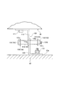
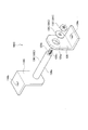
ここで、本実施形態では、図6および図7に示すように、照明装置1が、本体部10の高欄(設置台)82から路面81への落下を抑制する落下抑制部材100を備えるようにしている。 Here, in the present embodiment, as shown in FIGS. 6 and 7, the lighting device 1 is provided with a fall suppression member 100 that suppresses the fall of the main body 10 from the balustrade (installation table) 82 to the road surface 81. ing.

このように、照明装置1が落下抑制部材100を備えることで、設置部材50による本体部10の高欄(設置台)82の上面(設置面)82aへの設置が解除された際に、本体部10が高欄(設置台)82から落下してしまうのを抑制できるようにしている。なお、設置部材50による本体部10の高欄82の上面82aへの設置が解除される要因としては、設置部材50の破損や、ねじのゆるみによる各部材の固定の外れ(例えば、本体部側ブラケット51と本体部10との固定の外れ)などが考えられる。 In this way, when the lighting device 1 is provided with the fall suppression member 100, the main body portion 50 is released from the installation of the main body portion 10 on the upper surface (installation surface) 82a of the balustrade (installation table) 82. It is possible to prevent the 10 from falling from the balustrade (installation table) 82. It should be noted that the factors that cause the installation member 50 to release the installation of the main body 10 on the upper surface 82a of the balustrade 82 are the damage of the installation member 50 and the loosening of the screws to release the fixing of each member (for example, the main body side bracket). It is conceivable that the 51 and the main body 10 are not fixed).

本実施形態では、照明装置1は、2つの落下抑制部材100を備えており、各落下抑制部材100は、ハウジング11の下面(本体部10)に取り付けられる略L字状の本体部側ブラケット(本体部側取付部)110をそれぞれ備えている。また、各落下抑制部材100は、高欄82の上面82a等に固定される略L字状の設置面側ブラケット(設置台側取付部)120をそれぞれ備えている。これらの本体部側ブラケット110および設置面側ブラケット120は、例えば、金属板を直角に屈曲させることで形成することができる。 In the present embodiment, the lighting device 1 includes two fall suppression members 100, and each fall suppression member 100 is a substantially L-shaped main body side bracket (main body 10) attached to the lower surface (main body 10) of the housing 11. Main body side mounting part) 110 is provided respectively. Further, each fall suppressing member 100 includes a substantially L-shaped installation surface side bracket (installation stand side mounting portion) 120 fixed to the upper surface 82a or the like of the balustrade 82. These main body side brackets 110 and installation surface side brackets 120 can be formed, for example, by bending a metal plate at a right angle.

そして、各本体部側ブラケット110の水平方向に延在する部位には、取付孔110bがそれぞれ形成されている。そして、この取付孔110bにねじ111を挿入することで、ハウジング11の下面(本体部10)における設置部材50よりも長手方向の内側に、各本体部側ブラケット110の水平方向に延在する部位がそれぞれ固定されている(図3(b)参照)。 A mounting hole 110b is formed in each of the main body side brackets 110 extending in the horizontal direction. Then, by inserting the screw 111 into the mounting hole 110b, a portion extending in the horizontal direction of each main body side bracket 110 inside the installation member 50 on the lower surface (main body 10) of the housing 11 in the longitudinal direction. Are fixed (see FIG. 3 (b)).

一方、各設置面側ブラケット120の水平方向に延在する部位には、取付孔120bがそれぞれ形成されている。そして、この取付孔120bにねじ121を挿入することで、例えば、高欄(設置台)82の上面(設置面)82aに、各設置台側ブラケット120の水平方向に延在する部位がそれぞれ固定されている。 On the other hand, mounting holes 120b are formed in each of the installation surface side brackets 120 extending in the horizontal direction. Then, by inserting the screw 121 into the mounting hole 120b, for example, a portion extending in the horizontal direction of each mounting table side bracket 120 is fixed to the upper surface (installing surface) 82a of the balustrade (installation table) 82. ing.

また、本体部側ブラケット110および設置面側ブラケット120のそれぞれの垂直方向に延在する部位には、挿通孔110a,120aがそれぞれ形成されている。そして、設置部材50により本体部10を高欄82の上面82aに設置し、本体部側ブラケット110を本体部10に、設置面側ブラケット120を高欄82の上面82aに固定した状態で、挿通孔110a,120aが連通するようにしている。このように、本実施形態では、本体部側ブラケット110および設置面側ブラケット120の両方(本体部側ブラケット110および設置面側ブラケット120のうち少なくともいずれか一方の取付部)に、挿通孔110a,120aが形成されている。 Further, insertion holes 110a and 120a are formed in the portions extending in the vertical direction of the main body side bracket 110 and the installation surface side bracket 120, respectively. Then, the main body 10 is installed on the upper surface 82a of the balustrade 82 by the installation member 50, and the main body side bracket 110 is fixed to the main body 10 and the installation surface side bracket 120 is fixed to the upper surface 82a of the balustrade 82. , 120a communicate with each other. As described above, in the present embodiment, the insertion holes 110a, 120a is formed.

さらに、本実施形態では、落下抑制部材100は、挿通孔110a,120aに挿通される軸部と、軸部に設けられて、軸部が挿通孔110a,120aから抜けてしまうのを抑制する抜止部と、を有する保持部材130を備えている。 Further, in the present embodiment, the drop suppressing member 100 is provided on the shaft portion to be inserted into the insertion holes 110a and 120a and the shaft portion to prevent the shaft portion from coming out of the insertion holes 110a and 120a. It includes a holding member 130 having a portion and a portion.

そして、軸部を挿通孔110a,120aに挿通させ、抜止部によって軸部が挿通孔110a,120aから抜けてしまうのを抑制することで、保持部材130が、本体部側ブラケット110と設置面側ブラケット120とを相対回動可能に保持している。 Then, the shaft portion is inserted into the insertion holes 110a and 120a to prevent the shaft portion from coming out of the insertion holes 110a and 120a by the retaining portion, so that the holding member 130 can be moved to the main body side bracket 110 and the installation surface side. The bracket 120 is held so as to be relatively rotatable.

保持部材130は、図7に示すように、ボルト頭部131aとボルト軸部131bとを有するボルト131と、ボルト軸部131bに取り付けられるナット132と、を備えている。 As shown in FIG. 7, the holding member 130 includes a bolt 131 having a bolt head 131a and a bolt shaft portion 131b, and a nut 132 attached to the bolt shaft portion 131b.

本実施形態では、ボルト軸部131bの先端にねじ溝131cが形成されており、このねじ溝131cにナット132を螺合させることで、ボルト軸部131bにナット132が取り付けられる(締結される)ようになっている。なお、本実施形態では、輪郭形状が略六角形のボルト頭部131aおよびナット132を例示しているが、ボルト頭部やナットの輪郭形状は、これに限るものではなく、様々な形状(例えば略円形等)とすることができる。 In the present embodiment, a thread groove 131c is formed at the tip of the bolt shaft portion 131b, and the nut 132 is attached (fastened) to the bolt shaft portion 131b by screwing the nut 132 into the thread groove 131c. It has become like. In the present embodiment, the bolt head 131a and the nut 132 having a substantially hexagonal contour shape are illustrated, but the contour shape of the bolt head and the nut is not limited to this, and various shapes (for example, for example). It can be a substantially circular shape, etc.).

また、保持部材130は、ボルト軸部131bが挿入される貫通孔133aを有し、ボルト頭部131aとナット132とで挟持される筒状のスペーサ133を有している。本実施形態では、ワッシャ134およびワッシャ135を用いてナット132をボルト131に取り付けて(締結して)いる。すなわち、ボルト軸部131bにナット132を取り付けた(締結した)状態で、スペーサ133の軸方向の両端面がワッシャ134およびワッシャ135に接触するようにしている。このように、本実施形態では、スペーサ133は、ワッシャ134およびワッシャ135を介して、ボルト頭部131aおよびナット132によって挟持されている。 Further, the holding member 130 has a through hole 133a into which the bolt shaft portion 131b is inserted, and has a cylindrical spacer 133 sandwiched between the bolt head 131a and the nut 132. In this embodiment, the nut 132 is attached (fastened) to the bolt 131 by using the washer 134 and the washer 135. That is, with the nut 132 attached (fastened) to the bolt shaft portion 131b, both end faces in the axial direction of the spacer 133 are brought into contact with the washer 134 and the washer 135. As described above, in the present embodiment, the spacer 133 is sandwiched by the bolt head 131a and the nut 132 via the washer 134 and the washer 135.

また、本実施形態では、ボルト131は、ボルト頭部131aの外径が、スペーサ133の貫通孔133aの内径よりも大きく、ボルト軸部131bの外径が、スペーサ133の貫通孔133aの内径よりも小さくなるように形成されている。そして、ナット132は、外径がスペーサ133の貫通孔133aの内径よりも大きくなるように形成されている。 Further, in the present embodiment, the outer diameter of the bolt head 131a of the bolt 131 is larger than the inner diameter of the through hole 133a of the spacer 133, and the outer diameter of the bolt shaft portion 131b is larger than the inner diameter of the through hole 133a of the spacer 133. Is also formed to be small. The nut 132 is formed so that the outer diameter is larger than the inner diameter of the through hole 133a of the spacer 133.

また、スペーサ133の外径は、挿通孔110a,120aの連通部分に挿入することができる大きさとなっている。 The outer diameter of the spacer 133 is such that it can be inserted into the communication portions of the insertion holes 110a and 120a.

本実施形態では、挿通孔110a,120aは、内径がほぼ同径の円形に形成されている。そして、設置部材50により本体部10を高欄82の上面82aに設置し、本体部側ブラケット110を本体部10に、設置面側ブラケット120を高欄82の上面82aにそれぞれ固定した状態で、挿通孔110a,120aのほぼ全体が連通するようにしている。したがって、本実施形態では、スペーサ133は、外径が挿通孔110a,120aの内径よりも小さくなるように形成されている。 In the present embodiment, the insertion holes 110a and 120a are formed in a circular shape having substantially the same inner diameter. Then, the main body 10 is installed on the upper surface 82a of the balustrade 82 by the installation member 50, and the main body side bracket 110 is fixed to the main body 10 and the installation surface side bracket 120 is fixed to the upper surface 82a of the balustrade 82. Almost all of 110a and 120a communicate with each other. Therefore, in the present embodiment, the spacer 133 is formed so that the outer diameter is smaller than the inner diameters of the insertion holes 110a and 120a.

また、ワッシャ134およびワッシャ135の外径は、挿通孔110a,120aの連通部分への挿入が規制される大きさとなっている。すなわち、本実施形態では、ワッシャ134およびワッシャ135は、外径が挿通孔110a,120aの内径よりも大きくなるように形成されている。なお、ボルト頭部131aの外径およびナット132の外径は、挿通孔110a,120aの内径よりも大きいのが好ましいが、挿通孔110a,120aの内径以下であってもよい。 Further, the outer diameters of the washers 134 and the washer 135 have a size that restricts the insertion of the insertion holes 110a and 120a into the communication portions. That is, in the present embodiment, the washer 134 and the washer 135 are formed so that the outer diameter is larger than the inner diameter of the insertion holes 110a and 120a. The outer diameter of the bolt head 131a and the outer diameter of the nut 132 are preferably larger than the inner diameters of the insertion holes 110a and 120a, but may be smaller than the inner diameters of the insertion holes 110a and 120a.

さらに、スペーサ133は、軸方向の長さが、ボルト軸部131bの軸方向の長さよりも小さくなるようにしている。こうすることで、貫通孔133aに挿通させたボルト軸部131bの先端がスペーサ133から突出するようにしている。 Further, the spacer 133 has an axial length smaller than the axial length of the bolt shaft portion 131b. By doing so, the tip of the bolt shaft portion 131b inserted through the through hole 133a is made to protrude from the spacer 133.

また、スペーサ133は、軸方向の長さが、本体部側ブラケット110の垂直方向に延在する部位の厚さと設置面側ブラケット120の垂直方向に延在する部位の厚さとの和よりも大きくなるようにしている。こうすることで、貫通孔133aに挿通させたボルト軸部131bにナット132を取り付けた(締結した)際に、本体部側ブラケット110と設置面側ブラケット120との相対移動が保持部材130によって規制されてしまわないようにしている。 Further, the length of the spacer 133 in the axial direction is larger than the sum of the thickness of the portion extending in the vertical direction of the main body side bracket 110 and the thickness of the portion extending in the vertical direction of the installation surface side bracket 120. I am trying to be. By doing so, when the nut 132 is attached (fastened) to the bolt shaft portion 131b inserted through the through hole 133a, the relative movement between the main body side bracket 110 and the installation surface side bracket 120 is restricted by the holding member 130. I try not to be done.

このように、本実施形態では、保持部材130は、本体部側ブラケット110および設置面側ブラケット120に対して相対移動できるようにした状態で、本体部側ブラケット110と設置面側ブラケット120とを保持している。こうすることで、保持部材130が、本体部側ブラケット110と設置面側ブラケット120との相対回動を邪魔してしまうのを抑制できるようにしている。 As described above, in the present embodiment, the holding member 130 holds the main body side bracket 110 and the installation surface side bracket 120 in a state where the holding member 130 can move relative to the main body side bracket 110 and the installation surface side bracket 120. keeping. By doing so, it is possible to prevent the holding member 130 from interfering with the relative rotation between the main body side bracket 110 and the installation surface side bracket 120.

このような保持部材130は、例えば、下記のようにして組み付けることができる。 Such a holding member 130 can be assembled, for example, as follows.

まず、ボルト軸部131bをワッシャ134の貫通孔に挿入し、スペーサ133の貫通孔133aに挿通する。 First, the bolt shaft portion 131b is inserted into the through hole of the washer 134, and is inserted into the through hole 133a of the spacer 133.

次に、ボルト軸部133bが挿通されたスペーサ133を、互いに連通させた挿通孔110a,120aに挿通させる。 Next, the spacer 133 through which the bolt shaft portion 133b is inserted is inserted into the insertion holes 110a and 120a that communicate with each other.

そして、ボルト軸部131bのスペーサ133から突出した先端にワッシャ135を取り付ける。その後、ボルト軸部131bのスペーサ133から突出した先端に形成されたねじ溝131cにナット132を螺合させる。 Then, the washer 135 is attached to the tip of the bolt shaft portion 131b protruding from the spacer 133. After that, the nut 132 is screwed into the thread groove 131c formed at the tip protruding from the spacer 133 of the bolt shaft portion 131b.

こうして、挿通孔110a,120aに挿通される軸部と、軸部に設けられて、軸部が挿通孔110a,120aから抜けてしまうのを抑制する抜止部と、を有する保持部材130が組み付けられる。 In this way, the holding member 130 having a shaft portion to be inserted into the insertion holes 110a and 120a and a retaining portion provided in the shaft portion to prevent the shaft portion from coming out of the insertion holes 110a and 120a is assembled. ..

なお、保持部材130の組み付け方法は、上記の方法に限られるものではなく、様々な方法で組み付けることができる。 The method of assembling the holding member 130 is not limited to the above method, and the holding member 130 can be assembled by various methods.

また、本実施形態では、スペーサ133を、挿通孔110a,120aに挿通される軸部として機能させ、ワッシャ134およびワッシャ135を、軸部が挿通孔110a,120aから抜けてしまうのを抑制する抜止部として機能させている。すなわち、本実施形態では、スペーサ133が、互いに連通させた挿通孔110a,120aに挿通される軸部の少なくとも一部を構成している。そして、ワッシャ134およびワッシャ135が、軸部が挿通孔110a,120aから抜けてしまうのを抑制する抜止部の少なくとも一部を構成している。 Further, in the present embodiment, the spacer 133 is made to function as a shaft portion to be inserted into the insertion holes 110a and 120a, and the washer 134 and the washer 135 are removed to prevent the shaft portion from coming out of the insertion holes 110a and 120a. It is functioning as a department. That is, in the present embodiment, the spacer 133 constitutes at least a part of the shaft portion to be inserted into the insertion holes 110a and 120a communicating with each other. The washer 134 and the washer 135 form at least a part of a retaining portion that prevents the shaft portion from coming out of the insertion holes 110a and 120a.

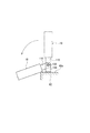
このような構成をした落下抑制部材100を設けることで、設置部材50による本体部10の高欄(設置台)82の上面(設置面)82aへの設置が解除された際には、本体部10は、例えば、図8に示すように回動することとなる。 By providing the fall suppression member 100 having such a configuration, when the installation of the main body 10 on the upper surface (installation surface) 82a of the main body 10 by the installation member 50 is released, the main body 10 is released. Will rotate, for example, as shown in FIG.

すなわち、設置部材50による本体部10の設置が解除された場合、本実施形態では、本体部10が2つの落下抑制部材100のみによって高欄82上に保持されることとなる。 That is, when the installation of the main body portion 10 by the installation member 50 is released, in the present embodiment, the main body portion 10 is held on the balustrade 82 only by the two fall suppressing members 100.

このとき、落下抑制部材100は、上述したように、本体部側ブラケット110と設置面側ブラケット120との相対移動が保持部材130によって規制されてしまわないようになっている。そして、保持部材130の軸部として機能するスペーサ133は、外径が挿通孔110a,120aの内径よりも小さくなるように形成されている。 At this time, as described above, the fall suppressing member 100 is prevented from being restricted by the holding member 130 in relative movement between the main body side bracket 110 and the installation surface side bracket 120. The spacer 133 that functions as the shaft portion of the holding member 130 is formed so that the outer diameter is smaller than the inner diameters of the insertion holes 110a and 120a.

したがって、本体部10を落下抑制部材100のみで高欄82上に保持した場合、本体部10は、自重によって、図9(a)に示すように、距離d1(挿通孔110a,120aの内径とスペーサ133の外径との差)だけ落下することになる。このとき、本体部10に固定されている本体部側ブラケット110も、距離d1(挿通孔110a,120aの内径とスペーサ133の外径との差)だけ落下することになる(図9(b)参照)。 Therefore, when the main body 10 is held on the balustrade 82 only by the fall suppressing member 100, the main body 10 has a distance d1 (inner diameters and spacers of the insertion holes 110a and 120a) due to its own weight, as shown in FIG. 9A. It will fall by the difference (difference from the outer diameter of 133). At this time, the main body side bracket 110 fixed to the main body 10 also drops by the distance d1 (the difference between the inner diameters of the insertion holes 110a and 120a and the outer diameter of the spacer 133) (FIG. 9B). reference).

さらに、保持部材130は、本体部側ブラケット110と設置面側ブラケット120とを相対回動可能に保持しているため、本体部側ブラケット110が設置面側ブラケット120に対して相対回動することとなる。このとき、本体部側ブラケット110には本体部10が取り付けられている(固定されている)ため、本体部側ブラケット110の設置面側ブラケット120に対する相対回動に伴って本体部10も回動することとなる。 Further, since the holding member 130 holds the main body side bracket 110 and the installation surface side bracket 120 so as to be relatively rotatable, the main body side bracket 110 rotates relative to the installation surface side bracket 120. It becomes. At this time, since the main body 10 is attached (fixed) to the main body side bracket 110, the main body 10 also rotates with the relative rotation of the main body side bracket 110 with respect to the installation surface side bracket 120. Will be done.

このように、本実施形態では、設置部材50による本体部10の高欄(設置台)82の上面(設置面)82aへの設置が解除された際には、本体部10が設置面側ブラケット120に対して相対回動することとなる。なお、本体部10の相対回動の方向は、図8に示す方向とは反対側となることもある。 As described above, in the present embodiment, when the installation member 50 releases the installation of the main body 10 on the upper surface (installation surface) 82a of the balustrade (installation table) 82, the main body 10 is mounted on the installation surface side bracket 120. It will rotate relative to the relative. The direction of relative rotation of the main body 10 may be opposite to the direction shown in FIG.

このような構成とすれば、設置部材50による本体部10の高欄(設置台)82の上面(設置面)82aへの設置が解除された際に、本体部10が路面81上に落下してしまうのを抑制することができる。また、本体部10が回動により傾くことになるため、設置部材50による設置が解除されていること(例えば、設置部材50が破損していることなど)を目視により確認することができる。 With such a configuration, when the installation of the main body 10 on the upper surface (installation surface) 82a of the balustrade (installation table) 82 by the installation member 50 is released, the main body 10 falls on the road surface 81. It can be suppressed from being stowed. Further, since the main body 10 is tilted by rotation, it can be visually confirmed that the installation by the installation member 50 is released (for example, the installation member 50 is damaged).

なお、本実施形態では、保持部材130は、本体部側ブラケット110および設置面側ブラケット120に対して相対移動できるようになっている。そのため、保持部材130は、挿通孔120a内を落下する際に、平行移動せずに一端が下方を向くように傾斜する場合もある。そして、保持部材130が傾斜した状態で落下した場合、本体部10および本体部側ブラケット110が距離d1以上落下する可能性もある。 In this embodiment, the holding member 130 can move relative to the main body side bracket 110 and the installation surface side bracket 120. Therefore, when the holding member 130 falls in the insertion hole 120a, the holding member 130 may incline so that one end thereof faces downward without moving in parallel. Then, when the holding member 130 falls in an inclined state, the main body portion 10 and the main body portion side bracket 110 may fall by a distance d1 or more.

しかしながら、保持部材130は、抜け止めがなされた状態で本体部側ブラケット110および設置面側ブラケット120を保持している。そのため、本実施形態にかかる落下抑制部材100を用いれば、本体部10の落下距離をスペーサ133の軸方向の長さよりも短くすることができる。 However, the holding member 130 holds the main body side bracket 110 and the installation surface side bracket 120 in a state where the holding member 130 is prevented from coming off. Therefore, if the fall suppression member 100 according to the present embodiment is used, the fall distance of the main body 10 can be made shorter than the axial length of the spacer 133.

以上説明したように、本実施形態にかかる照明装置1は、光源部21を有する本体部10と、本体部10を高欄(設置台)82に設置する設置部材50と、本体部10の落下を抑制する落下抑制部材100と、を備えている。 As described above, in the lighting device 1 according to the present embodiment, the main body 10 having the light source 21, the installation member 50 for installing the main body 10 on the balustrade (installation table) 82, and the main body 10 are dropped. It includes a fall suppressing member 100 for suppressing.

また、落下抑制部材100は、本体部10に取り付けられる本体部側ブラケット(本体部側取付部)110と、高欄(設置台)82に取り付けられる設置面側ブラケット(設置台側取付部)120と、を備えている。 Further, the fall suppression member 100 includes a main body side bracket (main body side mounting portion) 110 attached to the main body portion 10 and an installation surface side bracket (installation base side mounting portion) 120 attached to the balustrade (installation base) 82. , Is equipped.

そして、落下抑制部材100は、本体部側ブラケット(本体部側取付部)110と設置面側ブラケット(設置台側取付部)120とを相対回動可能に保持する保持部材130を備えている。 The fall suppression member 100 includes a holding member 130 that holds the main body side bracket (main body side mounting portion) 110 and the installation surface side bracket (installation base side mounting portion) 120 so as to be relatively rotatable.

こうすれば、設置部材50による本体部10の高欄(設置台)82への設置が解除された際に、本体部10が路面81上に落下してしまうのを抑制することができる。また、ワイヤを用いて吊り下げる構成とした場合のように、通常の設置状態において、撓んだワイヤが本体部からはみ出してしまうことが生じることがなくなるため、見栄えをより向上させることができる。 By doing so, it is possible to prevent the main body portion 10 from falling onto the road surface 81 when the installation of the main body portion 10 on the balustrade (installation stand) 82 by the installation member 50 is released. Further, unlike the case where the wire is used to suspend the wire, the bent wire does not protrude from the main body in the normal installation state, so that the appearance can be further improved.

このように、本実施形態によれば、高欄(設置台)82からの落下を抑制しつつ、見栄えをより向上させることのできる照明装置1を得ることができる。 As described above, according to the present embodiment, it is possible to obtain the lighting device 1 capable of further improving the appearance while suppressing the fall from the balustrade (installation table) 82.

また、本実施形態のように、本体部10の落下を抑制するために、本体部10を設置面側ブラケット120に対して相対回動させるようにすれば、ワイヤを用いて吊り下げる構成とした場合と較べて、本体部10の落下距離を小さくすることができる。すなわち、本実施形態によれば、本体部10の落下距離を比較的小さくすることができる。そのため、設置部材50による本体部10の高欄(設置台)82への設置が解除された際に、落下防止部材100に加えられる荷重が比較的小さくなる。その結果、落下抑制部材100の強度を高くしたり、落下抑制部材100の数を多くしたりする必要がなくなるため、コストの削減を図ることができる。 Further, as in the present embodiment, in order to suppress the fall of the main body portion 10, if the main body portion 10 is rotated relative to the installation surface side bracket 120, the main body portion 10 is suspended by using a wire. Compared with the case, the falling distance of the main body 10 can be reduced. That is, according to the present embodiment, the falling distance of the main body 10 can be made relatively small. Therefore, when the installation of the main body 10 on the balustrade (installation table) 82 by the installation member 50 is released, the load applied to the fall prevention member 100 becomes relatively small. As a result, it is not necessary to increase the strength of the fall suppressing member 100 or increase the number of the fall suppressing members 100, so that the cost can be reduced.

また、本実施形態では、本体部側ブラケット(本体部側取付部)110および設置面側ブラケット(設置台側取付部)120のうち少なくともいずれか一方の取付部に挿通孔110a,120aが形成されている。そして、保持部材130は、挿通孔110a,120aに挿通される軸部と、軸部に設けられ、軸部の挿通孔110a,120aからの抜けを抑制する抜止部と、を備えている。 Further, in the present embodiment, insertion holes 110a and 120a are formed in at least one of the main body side bracket (main body side mounting portion) 110 and the installation surface side bracket (installation base side mounting portion) 120. ing. The holding member 130 includes a shaft portion to be inserted into the insertion holes 110a and 120a, and a retaining portion provided on the shaft portion to prevent the shaft portion from coming out of the insertion holes 110a and 120a.

こうすれば、本体部10を回動させる落下抑制部材100の構成を簡素化させることができ、より容易に落下抑制部材100を得ることができる。 By doing so, the configuration of the fall suppressing member 100 that rotates the main body 10 can be simplified, and the falling suppressing member 100 can be obtained more easily.

また、本実施形態では、本体部側ブラケット(本体部側取付部)110および設置面側ブラケット(設置台側取付部)120に挿通孔110a,120aがそれぞれ形成されている。そして、保持部材130は、ボルト頭部131aとボルト軸部131bとを有するボルト131と、ボルト軸部131bに取り付けられるナット132と、を備えている。 Further, in the present embodiment, insertion holes 110a and 120a are formed in the main body side bracket (main body side mounting portion) 110 and the installation surface side bracket (installation base side mounting portion) 120, respectively. The holding member 130 includes a bolt 131 having a bolt head 131a and a bolt shaft portion 131b, and a nut 132 attached to the bolt shaft portion 131b.

さらに、保持部材130は、ボルト軸部131bが挿入される貫通孔133aを有し、ボルト頭部131aとナット132とで挟持される筒状のスペーサ133を備えている。そして、スペーサ133が、互いに連通させた挿通孔110a,120aに挿通される軸部の少なくとも一部を構成している。 Further, the holding member 130 has a through hole 133a into which the bolt shaft portion 131b is inserted, and includes a cylindrical spacer 133 sandwiched between the bolt head 131a and the nut 132. The spacer 133 constitutes at least a part of the shaft portion to be inserted into the insertion holes 110a and 120a that communicate with each other.

こうすれば、既存の部品を用いて落下抑制部材100を形成することができるため、コストのより一層の削減を図ることができる。 By doing so, the fall suppressing member 100 can be formed by using the existing parts, so that the cost can be further reduced.

また、本実施形態では、保持部材130が、本体部側ブラケット110および設置面側ブラケット120に対して相対移動できるようにした状態で、本体部側ブラケット110と設置面側ブラケット120とを保持している。すなわち、保持部材130、本体部側ブラケット110および設置面側ブラケット120がそれぞれ独立して他の部材に対して相対移動できるようになっている。こうすれば、保持部材130と本体部側ブラケット110とを固定する部位や保持部材130と設置面側ブラケット120とを固定する部位が形成されることがない。そのため、設置部材50による本体部10の高欄(設置台)82への設置が解除されて、保持部材130に本体部10の荷重が加えられた際に、応力集中が生じてしまうのを抑制することができる。その結果、落下抑制部材100が破損してしまうのをより確実に抑制することができる。 Further, in the present embodiment, the main body side bracket 110 and the installation surface side bracket 120 are held in a state where the holding member 130 can move relative to the main body side bracket 110 and the installation surface side bracket 120. ing. That is, the holding member 130, the main body side bracket 110, and the installation surface side bracket 120 can each independently move relative to other members. In this way, a portion for fixing the holding member 130 and the main body side bracket 110 and a portion for fixing the holding member 130 and the installation surface side bracket 120 are not formed. Therefore, the installation of the main body 10 on the balustrade (installation table) 82 by the installation member 50 is released, and when the load of the main body 10 is applied to the holding member 130, stress concentration is suppressed. be able to. As a result, it is possible to more reliably prevent the fall suppressing member 100 from being damaged.

なお、上記実施形態で示した保持部材130に替えて、図10に示す保持部材130Aを用いてもよい。 The holding member 130A shown in FIG. 10 may be used instead of the holding member 130 shown in the above embodiment.

図10に示す保持部材130Aは、ボルト頭部131aAとボルト軸部131bAとを有するボルト131Aと、ボルト軸部131bAに取り付けられるナット132と、を備えている。なお、図10では、輪郭形状が略円形のボルト頭部131aAを例示しているが、上記実施形態で示したように、輪郭形状が六角形のボルト頭部としてもよい。 The holding member 130A shown in FIG. 10 includes a bolt 131A having a bolt head 131aA and a bolt shaft portion 131bA, and a nut 132 attached to the bolt shaft portion 131bA. Although FIG. 10 illustrates a bolt head 131aA having a substantially circular contour shape, it may be a bolt head having a hexagonal contour shape as shown in the above embodiment.

また、図10では、ボルト軸部131bAは、ボルト頭部131aA側に形成される太径部131cAと、太径部131cAの先端側に同心状に連設される細径部131dAと、を備えている。さらに、図10では、細径部131dAの全体にねじ溝131eAが形成されている。そして、細径部131dAの全体に形成されたねじ溝131eAにナット132を螺合させることで、細径部131dAにナット132が取り付けられる(締結される)ようになっている。 Further, in FIG. 10, the bolt shaft portion 131bA includes a large diameter portion 131cA formed on the bolt head 131aA side and a small diameter portion 131dA concentrically connected to the tip end side of the large diameter portion 131cA. ing. Further, in FIG. 10, a thread groove 131eA is formed in the entire small diameter portion 131dA. Then, by screwing the nut 132 into the thread groove 131eA formed on the entire small diameter portion 131dA, the nut 132 is attached (fastened) to the small diameter portion 131dA.

また、図10に示す保持部材130Aにおいても、ワッシャ135が用いられており、細径部131dAにナット132を取り付けた(締結した)状態で、太径部131cAの先端面がワッシャ135に接触するようにしている。 Further, the washer 135 is also used in the holding member 130A shown in FIG. 10, and the tip surface of the large diameter portion 131cA comes into contact with the washer 135 with the nut 132 attached (fastened) to the small diameter portion 131dA. I am doing it.

また、ボルト131Aは、ボルト頭部131aAの外径が挿通孔110a,120aの連通部分への挿入が規制される大きさとなっている。具体的には、ボルト頭部131aAの外径は、太径部131cAの外径および挿通孔110a,120aの内径よりも大きくなるように形成されている。また、太径部131cAは、外径が挿通孔110a,120aの連通部分に挿入することができる大きさとなっている。すなわち、太径部131cAの外径が、挿通孔110a,120aの内径よりも小さくなるように形成されている。 Further, the bolt 131A has a size such that the outer diameter of the bolt head 131aA is restricted from being inserted into the communication portions of the insertion holes 110a and 120a. Specifically, the outer diameter of the bolt head 131aA is formed to be larger than the outer diameter of the large diameter portion 131cA and the inner diameters of the insertion holes 110a and 120a. Further, the large diameter portion 131cA has an outer diameter large enough to be inserted into the communication portions of the insertion holes 110a and 120a. That is, the outer diameter of the large diameter portion 131cA is formed to be smaller than the inner diameter of the insertion holes 110a and 120a.

また、ワッシャ135の外径は、挿通孔110a,120aの連通部分への挿入が規制される大きさとなっている。すなわち、ワッシャ135は、外径が挿通孔110a,120aの内径よりも大きくなるように形成されている。なお、ナット132の外径は、挿通孔110a,120aの内径よりも大きいのが好ましいが、挿通孔110a,120aの内径以下であってもよい。 Further, the outer diameter of the washer 135 is such that the insertion of the insertion holes 110a and 120a into the communication portion is restricted. That is, the washer 135 is formed so that the outer diameter is larger than the inner diameter of the insertion holes 110a and 120a. The outer diameter of the nut 132 is preferably larger than the inner diameter of the insertion holes 110a and 120a, but may be smaller than the inner diameter of the insertion holes 110a and 120a.

さらに、太径部131cAは、軸方向の長さが、本体部側ブラケット110の垂直方向に延在する部位の厚さと設置面側ブラケット120の垂直方向に延在する部位の厚さとの和よりも大きくなるようにしている。 Further, in the large diameter portion 131cA, the axial length is calculated from the sum of the thickness of the portion extending in the vertical direction of the main body side bracket 110 and the thickness of the portion extending in the vertical direction of the installation surface side bracket 120. Is also trying to grow.

このように、図10に示す保持部材130Aにおいては、太径部131cAを、挿通孔110a,120aに挿通される軸部として機能させている。そして、ボルト頭部131aAおよびワッシャ135を、軸部が挿通孔110a,120aから抜けてしまうのを抑制する抜止部として機能させている。 As described above, in the holding member 130A shown in FIG. 10, the large diameter portion 131cA functions as a shaft portion to be inserted into the insertion holes 110a and 120a. Then, the bolt head 131aA and the washer 135 are made to function as a retaining portion for suppressing the shaft portion from coming off from the insertion holes 110a and 120a.

このような保持部材130Aは、例えば、下記のようにして組み付けることができる。 Such a holding member 130A can be assembled, for example, as follows.

まず、ボルト軸部131bの太径部131cAを、互いに連通させた挿通孔110a,120aに挿通させる。 First, the large diameter portion 131cA of the bolt shaft portion 131b is inserted into the insertion holes 110a and 120a that communicate with each other.

そして、ボルト軸部131bの細径部131dAにワッシャ135を取り付ける。その後、ボルト軸部131bの細径部131dAに形成されたねじ溝131eAにナット132を螺合させる。 Then, the washer 135 is attached to the small diameter portion 131dA of the bolt shaft portion 131b. After that, the nut 132 is screwed into the thread groove 131eA formed in the small diameter portion 131dA of the bolt shaft portion 131b.

こうして、挿通孔110a,120aに挿通される軸部と、軸部に設けられて、軸部が挿通孔110a,120aから抜けてしまうのを抑制する抜止部と、を有する保持部材130Aが組み付けられる。 In this way, the holding member 130A having a shaft portion to be inserted into the insertion holes 110a and 120a and a retaining portion provided in the shaft portion to prevent the shaft portion from coming out of the insertion holes 110a and 120a is assembled. ..

なお、保持部材130Aの組み付け方法は、上記の方法に限られるものではなく、様々な方法で組み付けることができる。 The method of assembling the holding member 130A is not limited to the above method, and can be assembled by various methods.

このような保持部材130Aを用いても、上記実施形態とほぼ同様の作用、効果を奏することができる。 Even if such a holding member 130A is used, almost the same operation and effect as those of the above embodiment can be obtained.

また、図11に示す保持部材130Bを用いてもよい。 Further, the holding member 130B shown in FIG. 11 may be used.

図11に示す保持部材130Bは、ボルト頭部131aBとボルト軸部131bBとを有するボルト131Bと、ボルト軸部131bBに取り付けられるEリング132Bと、を備えている。なお、図11では、輪郭形状が略円形のボルト頭部131aBを例示しているが、上記実施形態で示したように、輪郭形状が六角形のボルト頭部としてもよい。 The holding member 130B shown in FIG. 11 includes a bolt 131B having a bolt head 131aB and a bolt shaft portion 131bB, and an E-ring 132B attached to the bolt shaft portion 131bB. Although FIG. 11 illustrates a bolt head 131aB having a substantially circular contour shape, it may be a bolt head having a hexagonal contour shape as shown in the above embodiment.

また、図11では、ボルト軸部131bBの先端側には、Eリング132Bが取り付けられる溝部131cBが形成されている。 Further, in FIG. 11, a groove portion 131cB to which the E-ring 132B is attached is formed on the tip end side of the bolt shaft portion 131bB.

また、ボルト131Bは、ボルト頭部131aBの外径が挿通孔110a,120aの連通部分への挿入が規制される大きさとなっている。すなわち、ボルト頭部131aBの外径が挿通孔110a,120aの内径よりも大きくなるように形成されている。また、ボルト軸部131bBは、外径が挿通孔110a,120aの連通部分に挿入することができる大きさとなっている。すなわち、ボルト軸部131bBの外径が、挿通孔110a,120aの内径よりも小さくなるように形成されている。 Further, the bolt 131B has a size such that the outer diameter of the bolt head 131aB is restricted from being inserted into the communication portions of the insertion holes 110a and 120a. That is, the outer diameter of the bolt head 131aB is formed to be larger than the inner diameter of the insertion holes 110a and 120a. Further, the bolt shaft portion 131bB has an outer diameter such that it can be inserted into the communication portions of the insertion holes 110a and 120a. That is, the outer diameter of the bolt shaft portion 131bB is formed to be smaller than the inner diameter of the insertion holes 110a and 120a.

また、Eリング132Bの外径は、挿通孔110a,120aの連通部分への挿入が規制される大きさとなっている。すなわち、Eリング132Bは、外径が挿通孔110a,120aの内径よりも大きくなるように形成されている。 The outer diameter of the E-ring 132B is such that insertion of the insertion holes 110a and 120a into the communication portion is restricted. That is, the E-ring 132B is formed so that the outer diameter is larger than the inner diameters of the insertion holes 110a and 120a.

さらに、ボルト軸部131bBは、溝部131cBよりもボルト頭部131aB側の軸方向の長さが、本体部側ブラケット110の垂直方向に延在する部位の厚さと設置面側ブラケット120の垂直方向に延在する部位の厚さとの和よりも大きくなっている。 Further, the bolt shaft portion 131bB has an axial length of the bolt head 131aB side of the groove portion 131cB in the thickness of the portion extending in the vertical direction of the main body side bracket 110 and the vertical direction of the installation surface side bracket 120. It is larger than the sum of the thickness of the extending part.

このように、図11に示す保持部材130Bにおいては、ボルト軸部131bBにおける溝部131cBよりもボルト頭部131aB側を、挿通孔110a,120aに挿通される軸部として機能させている。そして、ボルト頭部131aBおよびEリング132Bを、軸部が挿通孔110a,120aから抜けてしまうのを抑制する抜止部として機能させている。 As described above, in the holding member 130B shown in FIG. 11, the bolt head 131aB side of the bolt shaft portion 131bB is made to function as a shaft portion to be inserted into the insertion holes 110a and 120a. Then, the bolt head 131aB and the E-ring 132B are made to function as a retaining portion for suppressing the shaft portion from coming off from the insertion holes 110a and 120a.

このような保持部材130Bは、例えば、下記のようにして組み付けることができる。 Such a holding member 130B can be assembled, for example, as follows.

まず、ボルト131Bのボルト軸部131bBを、互いに連通させた挿通孔110a,120aに挿通させる。そして、ボルト軸部131bBの溝部131cBにEリング132Bを取り付ける。 First, the bolt shaft portion 131bB of the bolt 131B is inserted into the insertion holes 110a and 120a that communicate with each other. Then, the E ring 132B is attached to the groove 131cB of the bolt shaft portion 131bB.

こうして、挿通孔110a,120aに挿通される軸部と、軸部に設けられて、軸部が挿通孔110a,120aから抜けてしまうのを抑制する抜止部と、を有する保持部材130Bが組み付けられる。 In this way, the holding member 130B having a shaft portion to be inserted into the insertion holes 110a and 120a and a retaining portion provided in the shaft portion to prevent the shaft portion from coming out of the insertion holes 110a and 120a is assembled. ..

なお、保持部材130Bの組み付け方法は、上記の方法に限られるものではなく、様々な方法で組み付けることができる。 The method of assembling the holding member 130B is not limited to the above method, and can be assembled by various methods.

このような保持部材130Bを用いても、上記実施形態とほぼ同様の作用、効果を奏することができる。 Even if such a holding member 130B is used, almost the same operation and effect as those of the above embodiment can be obtained.

また、上記実施形態で示した落下抑制部材100に替えて、図12に示す落下抑制部材100Cを用いてもよい。 Further, the fall suppressing member 100C shown in FIG. 12 may be used instead of the fall suppressing member 100 shown in the above embodiment.

図12に示す落下抑制部材100Cは、ハウジング11の下面(本体部10)に取り付けられる略L字状の本体部側ブラケット(本体部側取付部)110Cを備えている。また、落下抑制部材100Cは、高欄82の上面82a等に固定される略L字状の設置面側ブラケット(設置台側取付部)120を備えている。これらの本体部側ブラケット110Cおよび設置面側ブラケット120は、例えば、金属板を直角に屈曲させることで形成することができる。 The fall suppression member 100C shown in FIG. 12 includes a substantially L-shaped main body side bracket (main body side mounting portion) 110C that is attached to the lower surface (main body portion 10) of the housing 11. Further, the fall suppression member 100C includes a substantially L-shaped installation surface side bracket (installation stand side attachment portion) 120 fixed to the upper surface 82a or the like of the balustrade 82. These main body side brackets 110C and installation surface side brackets 120 can be formed, for example, by bending a metal plate at a right angle.

また、本体部側ブラケット110Cの水平方向に延在する部位には、取付孔110bが形成されており、取付孔110bにねじ111を挿入することで、本体部側ブラケット110Cの水平方向に延在する部位がハウジング11の下面に固定されている。 Further, a mounting hole 110b is formed in a portion of the main body side bracket 110C extending in the horizontal direction, and by inserting a screw 111 into the mounting hole 110b, the main body side bracket 110C extends in the horizontal direction. The portion to be used is fixed to the lower surface of the housing 11.

一方、設置面側ブラケット120の水平方向に延在する部位には取付孔120bが形成されており、取付孔120bにねじ121を挿入することで、設置台側ブラケット120の水平方向に延在する部位が高欄82の上面82aに固定されている。 On the other hand, a mounting hole 120b is formed in a portion of the installation surface side bracket 120 extending in the horizontal direction, and by inserting a screw 121 into the mounting hole 120b, the mounting base side bracket 120 extends in the horizontal direction. The portion is fixed to the upper surface 82a of the balustrade 82.

また、本体部側ブラケット110Cおよび設置面側ブラケット120のうち少なくともいずれか一方の取付部である設置面側ブラケット120の垂直方向に延在する部位には、挿通孔120aが形成されている。 Further, an insertion hole 120a is formed in a portion extending in the vertical direction of the installation surface side bracket 120, which is an attachment portion of at least one of the main body side bracket 110C and the installation surface side bracket 120.

そして、他方の取付部である本体部側ブラケット110Cの垂直方向に延在する部位には、保持部材130Cの軸部136が一体に形成されている。保持部材130Cは、挿通孔120aに挿通される軸部136と、軸部136に設けられて、軸部136が挿通孔120aから抜けてしまうのを抑制する抜止部と、を有している。 A shaft portion 136 of the holding member 130C is integrally formed at a portion extending in the vertical direction of the main body side bracket 110C, which is the other mounting portion. The holding member 130C has a shaft portion 136 to be inserted into the insertion hole 120a, and a retaining portion provided in the shaft portion 136 to prevent the shaft portion 136 from coming out of the insertion hole 120a.

そして、軸部136を挿通孔120aに挿通させ、抜止部によって軸部136が挿通孔120aから抜けてしまうのを抑制することで、保持部材130Cが、本体部側ブラケット110Cと設置面側ブラケット120とを相対回動可能に保持している。 Then, the shaft portion 136 is inserted into the insertion hole 120a to prevent the shaft portion 136 from coming out of the insertion hole 120a by the retaining portion, so that the holding member 130C has the main body portion side bracket 110C and the installation surface side bracket 120. Is held so that it can rotate relative to each other.

図12に示す軸部136は、本体部側ブラケット110C側に形成される太径部136aと、太径部136aの先端側に同心状に連設される細径部136bと、を備えている。さらに、図12では、細径部136bの全体にねじ溝136cが形成されている。そして、細径部136bの全体に形成されたねじ溝136cにナット132を螺合させることで、細径部136bにナット132が取り付けられる(締結される)ようになっている。 The shaft portion 136 shown in FIG. 12 includes a large-diameter portion 136a formed on the main body side bracket 110C side and a small-diameter portion 136b concentrically connected to the tip end side of the large-diameter portion 136a. .. Further, in FIG. 12, a thread groove 136c is formed in the entire small diameter portion 136b. Then, the nut 132 is attached (fastened) to the small diameter portion 136b by screwing the nut 132 into the thread groove 136c formed on the entire small diameter portion 136b.

また、図12に示す保持部材130Cにおいても、ワッシャ135が用いられており、細径部136bにナット132を取り付けた(締結した)状態で、太径部136aの先端面がワッシャ135に接触するようにしている。 Further, the washer 135 is also used in the holding member 130C shown in FIG. 12, and the tip surface of the large diameter portion 136a comes into contact with the washer 135 in a state where the nut 132 is attached (fastened) to the small diameter portion 136b. I am doing it.

また、太径部136aの外径が挿通孔120aの内径よりも小さくなるように形成されており、ワッシャ135の外径が挿通孔120aの内径よりも大きくなるように形成されている。なお、ナット132の外径は、挿通孔120aの内径よりも大きいのが好ましいが、挿通孔120aの内径以下であってもよい。 Further, the outer diameter of the large diameter portion 136a is formed to be smaller than the inner diameter of the insertion hole 120a, and the outer diameter of the washer 135 is formed to be larger than the inner diameter of the insertion hole 120a. The outer diameter of the nut 132 is preferably larger than the inner diameter of the insertion hole 120a, but may be equal to or less than the inner diameter of the insertion hole 120a.

さらに、太径部136aは、軸方向の長さが、設置面側ブラケット120の垂直方向に延在する部位の厚さよりも大きくなるようにしている。 Further, the large diameter portion 136a is set so that the length in the axial direction is larger than the thickness of the portion extending in the vertical direction of the installation surface side bracket 120.

このように、図12に示す保持部材130Cにおいては、太径部136aを、挿通孔120aに挿通される軸部136として機能させ、ワッシャ135を、軸部136が挿通孔120aから抜けてしまうのを抑制する抜止部として機能させている。 As described above, in the holding member 130C shown in FIG. 12, the large diameter portion 136a functions as the shaft portion 136 to be inserted into the insertion hole 120a, and the washer 135 is pulled out from the insertion hole 120a. It functions as a retaining part that suppresses.

このような保持部材130Cは、例えば、下記のようにして組み付けることができる。 Such a holding member 130C can be assembled, for example, as follows.

まず、太径部136aを挿通孔120aに挿通させる。そして、細径部136bにワッシャ135を取り付ける。その後、細径部136bに形成されたねじ溝136cにナット132を螺合させる。 First, the large diameter portion 136a is inserted into the insertion hole 120a. Then, the washer 135 is attached to the small diameter portion 136b. After that, the nut 132 is screwed into the thread groove 136c formed in the small diameter portion 136b.

こうして、挿通孔120aに挿通される軸部136と、軸部136に設けられて、軸部136が挿通孔120aから抜けてしまうのを抑制する抜止部と、を有する保持部材130Cが組み付けられる。 In this way, the holding member 130C having the shaft portion 136 to be inserted into the insertion hole 120a and the retaining portion provided in the shaft portion 136 to prevent the shaft portion 136 from coming out of the insertion hole 120a is assembled.

なお、保持部材130Cの組み付け方法は、上記の方法に限られるものではなく、様々な方法で組み付けることができる。 The method of assembling the holding member 130C is not limited to the above method, and can be assembled by various methods.

また、本体部側ブラケット110Cを挿通孔が形成される一方の取付部とし、設置面側ブラケット120を軸部が一体に形成される他方の取付部となるようにしてもよい。 Further, the main body side bracket 110C may be used as one mounting portion on which the insertion hole is formed, and the installation surface side bracket 120 may be used as the other mounting portion on which the shaft portion is integrally formed.

このような保持部材130Cを用いても、上記実施形態とほぼ同様の作用、効果を奏することができる。 Even if such a holding member 130C is used, almost the same operation and effect as those of the above embodiment can be obtained.

以上、本開示の好適な実施形態について説明したが、上記各実施形態には限定されず、種々の変形が可能である。 Although the preferred embodiments of the present disclosure have been described above, the present invention is not limited to the above embodiments, and various modifications are possible.

例えば、上記実施形態およびその変形例では、照明装置として、道路の側部に設けられた高欄の上面等に設置される低位置照明装置を例示したが、これに限定されるものではない。例えば、台上に据え置く据置タイプの照明装置に本開示を適用することも可能である。 For example, in the above-described embodiment and its modification, as the lighting device, a low-position lighting device installed on the upper surface of a balustrade provided on a side of a road or the like has been exemplified, but the lighting device is not limited thereto. For example, the present disclosure can be applied to a stationary type lighting device that is stationary on a table.

また、上記実施形態およびその変形例では、LEDを光源として用いたものを例示したが、半導体光源等を用いることも可能である。 Further, in the above-described embodiment and its modification, an example using an LED as a light source is illustrated, but a semiconductor light source or the like can also be used.

また、上記実施形態およびその変形例では、ワッシャ134およびワッシャ135を抜止部として機能させたものを例示したが、ボルト軸部やナットを抜止部として機能させるようにしてもよい。 Further, in the above-described embodiment and its modification, the washer 134 and the washer 135 function as the retaining portion, but the bolt shaft portion and the nut may function as the retaining portion.

また、上記実施形態およびその変形例で示した構成を適宜組み合わせて落下抑制部材を形成することも可能である。 Further, it is also possible to form a fall suppressing member by appropriately combining the configurations shown in the above-described embodiment and its modified examples.

また、設置部材や本体部、その他細部のスペック(形状、大きさ、レイアウト等)も適宜に変更可能である。 In addition, the specifications (shape, size, layout, etc.) of the installation member, the main body, and other details can be changed as appropriate.

1 照明装置
10 本体部
21 光源部
50 設置部材
82 高欄(設置台)
100,100C 落下抑制部材
110,110C 本体部側ブラケット(本体部側取付部)
110a 挿通孔
120 設置面側ブラケット(設置台側取付部)
120a 挿通孔
130,130A,130B,130C 保持部材
131,131A,131B ボルト
131a,131aA,131aB ボルト頭部
131b,131bA,131bB ボルト軸部
132 ナット
133 スペーサ(軸部)
133a 貫通孔
134 ワッシャ(抜止部)
135 ワッシャ(抜止部)
136 軸部
1 Lighting device 10 Main body 21 Light source 50 Installation member 82 High column (installation stand)
100,100C Fall suppression member 110,110C Main body side bracket (main body side mounting part)
110a Insertion hole 120 Installation surface side bracket (Installation stand side mounting part)
120a Insertion holes 130, 130A, 130B, 130C Holding members 131, 131A, 131B Bolt 131a, 131aA, 131aB Bolt head 131b, 131bA, 131bB Bolt shaft part 132 Nut 133 Spacer (shaft part)
133a Through hole 134 washer (retaining part)
135 washer (retaining part)
136 shaft

Claims (4)

光源部を有する本体部と、
前記本体部を設置台に設置する設置部材と、
前記本体部の落下を抑制する落下抑制部材と、
を備え、
前記落下抑制部材は、
前記本体部に取り付けられる本体部側取付部と、
前記設置台に取り付けられる設置台側取付部と、
前記本体部側取付部と前記設置台側取付部とを相対回動可能に保持する保持部材と、
を備えることを特徴とする照明装置。
The main body having a light source and
An installation member that installs the main body on the installation table,
A fall suppression member that suppresses the fall of the main body,
With
The fall suppressing member is
The main body side mounting part to be attached to the main body, and
The mounting part on the mounting stand side that can be mounted on the mounting stand,
A holding member that rotatably holds the main body side mounting portion and the installation base side mounting portion,
A lighting device characterized by being provided with.
前記本体部側取付部および前記設置台側取付部のうち少なくともいずれか一方の取付部に挿通孔が形成されており、
前記保持部材は、
前記挿通孔に挿通される軸部と、
前記軸部に設けられ、前記軸部の前記挿通孔からの抜けを抑制する抜止部と、
を備えることを特徴とする請求項1に記載の照明装置。
An insertion hole is formed in at least one of the main body side mounting portion and the installation base side mounting portion.
The holding member is
The shaft portion to be inserted into the insertion hole and
A retaining portion provided on the shaft portion to prevent the shaft portion from coming off from the insertion hole, and a retaining portion.
The lighting device according to claim 1, further comprising.
前記本体部側取付部および前記設置台側取付部に前記挿通孔がそれぞれ形成されており、
前記保持部材は、
ボルト頭部とボルト軸部とを有するボルトと、
前記ボルト軸部に取り付けられるナットと、
前記ボルト軸部が挿入される貫通孔を有し、前記ボルト頭部と前記ナットとで挟持される筒状のスペーサと、
を備え、
前記スペーサが、互いに連通させた前記挿通孔に挿通される前記軸部の少なくとも一部を構成していることを特徴とする請求項2に記載の照明装置。
The insertion holes are formed in the main body side mounting portion and the installation base side mounting portion, respectively.
The holding member is
A bolt having a bolt head and a bolt shaft,
The nut attached to the bolt shaft and
A cylindrical spacer having a through hole into which the bolt shaft portion is inserted and sandwiched between the bolt head and the nut,
With
The lighting device according to claim 2, wherein the spacers form at least a part of the shaft portion to be inserted into the insertion holes that communicate with each other.
前記本体部側取付部および前記設置台側取付部のうち一方の取付部に挿通孔が形成されており、
前記保持部材は、
他方の取付部に一体に形成され、前記挿通孔に挿入される前記軸部と、
前記軸部の先端側に設けられ、前記軸部の前記挿通孔からの抜けを抑制する前記抜止部と、
を有することを特徴とする請求項2に記載の照明装置。
An insertion hole is formed in one of the main body side mounting portion and the installation base side mounting portion.
The holding member is
With the shaft portion integrally formed with the other mounting portion and inserted into the insertion hole,
A retaining portion provided on the tip end side of the shaft portion to prevent the shaft portion from coming out of the insertion hole, and a retaining portion.
The lighting device according to claim 2, wherein the lighting device has.
JP2018034072A 2018-02-28 2018-02-28 Lighting device Active JP6956367B2 (en)

Priority Applications (1)

Application Number Priority Date Filing Date Title
JP2018034072A JP6956367B2 (en) 2018-02-28 2018-02-28 Lighting device

Applications Claiming Priority (1)

Application Number Priority Date Filing Date Title
JP2018034072A JP6956367B2 (en) 2018-02-28 2018-02-28 Lighting device

Publications (2)

Publication Number Publication Date
JP2019149316A JP2019149316A (en) 2019-09-05
JP6956367B2 true JP6956367B2 (en) 2021-11-02

Family

ID=67850715

Family Applications (1)

Application Number Title Priority Date Filing Date
JP2018034072A Active JP6956367B2 (en) 2018-02-28 2018-02-28 Lighting device

Country Status (1)

Country Link
JP (1) JP6956367B2 (en)

Families Citing this family (2)

* Cited by examiner, † Cited by third party
Publication number Priority date Publication date Assignee Title
JP7235699B2 (en) * 2020-06-30 2023-03-08 コイト電工株式会社 lighting equipment
JP7462494B2 (en) 2020-07-03 2024-04-05 星和電機株式会社 Wall mounting structure

Family Cites Families (3)

* Cited by examiner, † Cited by third party
Publication number Priority date Publication date Assignee Title
JP5652015B2 (en) * 2010-06-17 2015-01-14 東芝ライテック株式会社 lighting equipment
JP6643670B2 (en) * 2015-04-14 2020-02-12 パナソニックIpマネジメント株式会社 lighting equipment
JP6635373B2 (en) * 2015-12-18 2020-01-22 パナソニックIpマネジメント株式会社 Lighting device and connection structure of lighting device

Also Published As

Publication number Publication date
JP2019149316A (en) 2019-09-05

Similar Documents

Publication Publication Date Title
US8371726B2 (en) Recessed luminaire with a reflector
JP6956367B2 (en) Lighting device
JP6138164B2 (en) Easy-to-install lighting fixtures and mounting arrangements
KR100937904B1 (en) Banner hanger for the street lamp
CA2570789A1 (en) Lighting fixture with smooth adjustable beam width
WO2006060392A3 (en) Hybrid optics for l.e.d. lamp
KR20160028261A (en) LED Street Lamp For Adjusting An Irradiation Angle
US20160003455A1 (en) Lighting Housing Having Self-Adjusting Hinge Mechanism
EP2020561B1 (en) Luminaire
JP5498001B2 (en) lighting equipment
JP6635373B2 (en) Lighting device and connection structure of lighting device
KR101595934B1 (en) Fluorescent light compatible lamp appratus
JP6624560B2 (en) Lighting device and method of assembling reflector
JP5473055B2 (en) lighting equipment
JP6531466B2 (en) Luminaire and method of manufacturing the same
KR101104855B1 (en) Beam-Adjustable Wall Light
CN208222235U (en) A kind of street lamp shade conducive to heat dissipation
JP6815188B2 (en) Lighting device
KR101936830B1 (en) Lighting LED lamp
EP1847764A3 (en) Column lighting device
JP2007035292A (en) Illumination device
KR101906898B1 (en) Lighting Apparatus
JP2013131299A (en) Lamp fitting
KR102263297B1 (en) housing for light device
KR20190009532A (en) Outdoor lighting apparatus for preventing light pollution

Legal Events

Date Code Title Description
A621 Written request for application examination

Free format text: JAPANESE INTERMEDIATE CODE: A621

Effective date: 20201022

A977 Report on retrieval

Free format text: JAPANESE INTERMEDIATE CODE: A971007

Effective date: 20210827

A01 Written decision to grant a patent or to grant a registration (utility model)

Free format text: JAPANESE INTERMEDIATE CODE: A01

Effective date: 20210914

A61 First payment of annual fees (during grant procedure)

Free format text: JAPANESE INTERMEDIATE CODE: A61

Effective date: 20210916