JP6955005B2 - Chemical ablation device used to treat arrhythmia - Google Patents
Chemical ablation device used to treat arrhythmia Download PDFInfo
- Publication number
- JP6955005B2 JP6955005B2 JP2019522428A JP2019522428A JP6955005B2 JP 6955005 B2 JP6955005 B2 JP 6955005B2 JP 2019522428 A JP2019522428 A JP 2019522428A JP 2019522428 A JP2019522428 A JP 2019522428A JP 6955005 B2 JP6955005 B2 JP 6955005B2
- Authority
- JP
- Japan
- Prior art keywords
- ablation
- needle
- clamp
- chemical
- reagent
- Prior art date
- Legal status (The legal status is an assumption and is not a legal conclusion. Google has not performed a legal analysis and makes no representation as to the accuracy of the status listed.)
- Active
Links
Images


Classifications
-
- A—HUMAN NECESSITIES
- A61—MEDICAL OR VETERINARY SCIENCE; HYGIENE
- A61B—DIAGNOSIS; SURGERY; IDENTIFICATION
- A61B18/00—Surgical instruments, devices or methods for transferring non-mechanical forms of energy to or from the body
- A61B18/04—Surgical instruments, devices or methods for transferring non-mechanical forms of energy to or from the body by heating
- A61B18/06—Surgical instruments, devices or methods for transferring non-mechanical forms of energy to or from the body by heating caused by chemical reaction, e.g. moxaburners
-
- A—HUMAN NECESSITIES
- A61—MEDICAL OR VETERINARY SCIENCE; HYGIENE
- A61M—DEVICES FOR INTRODUCING MEDIA INTO, OR ONTO, THE BODY; DEVICES FOR TRANSDUCING BODY MEDIA OR FOR TAKING MEDIA FROM THE BODY; DEVICES FOR PRODUCING OR ENDING SLEEP OR STUPOR
- A61M25/00—Catheters; Hollow probes
- A61M25/0067—Catheters; Hollow probes characterised by the distal end, e.g. tips
- A61M25/0082—Catheter tip comprising a tool
- A61M25/0084—Catheter tip comprising a tool being one or more injection needles
-
- A—HUMAN NECESSITIES
- A61—MEDICAL OR VETERINARY SCIENCE; HYGIENE
- A61B—DIAGNOSIS; SURGERY; IDENTIFICATION
- A61B17/00—Surgical instruments, devices or methods, e.g. tourniquets
- A61B17/28—Surgical forceps
- A61B17/2812—Surgical forceps with a single pivotal connection
-
- A—HUMAN NECESSITIES
- A61—MEDICAL OR VETERINARY SCIENCE; HYGIENE
- A61B—DIAGNOSIS; SURGERY; IDENTIFICATION
- A61B17/00—Surgical instruments, devices or methods, e.g. tourniquets
- A61B17/28—Surgical forceps
- A61B17/2812—Surgical forceps with a single pivotal connection
- A61B17/282—Jaws
-
- A—HUMAN NECESSITIES
- A61—MEDICAL OR VETERINARY SCIENCE; HYGIENE
- A61B—DIAGNOSIS; SURGERY; IDENTIFICATION
- A61B17/00—Surgical instruments, devices or methods, e.g. tourniquets
- A61B17/34—Trocars; Puncturing needles
-
- A—HUMAN NECESSITIES
- A61—MEDICAL OR VETERINARY SCIENCE; HYGIENE
- A61B—DIAGNOSIS; SURGERY; IDENTIFICATION
- A61B5/00—Measuring for diagnostic purposes; Identification of persons
- A61B5/24—Detecting, measuring or recording bioelectric or biomagnetic signals of the body or parts thereof
- A61B5/25—Bioelectric electrodes therefor
- A61B5/279—Bioelectric electrodes therefor specially adapted for particular uses
- A61B5/28—Bioelectric electrodes therefor specially adapted for particular uses for electrocardiography [ECG]
- A61B5/282—Holders for multiple electrodes
-
- A—HUMAN NECESSITIES
- A61—MEDICAL OR VETERINARY SCIENCE; HYGIENE
- A61B—DIAGNOSIS; SURGERY; IDENTIFICATION
- A61B5/00—Measuring for diagnostic purposes; Identification of persons
- A61B5/24—Detecting, measuring or recording bioelectric or biomagnetic signals of the body or parts thereof
- A61B5/316—Modalities, i.e. specific diagnostic methods
- A61B5/318—Heart-related electrical modalities, e.g. electrocardiography [ECG]
- A61B5/346—Analysis of electrocardiograms
- A61B5/349—Detecting specific parameters of the electrocardiograph cycle
- A61B5/364—Detecting abnormal ECG interval, e.g. extrasystoles, ectopic heartbeats
-
- A—HUMAN NECESSITIES
- A61—MEDICAL OR VETERINARY SCIENCE; HYGIENE
- A61B—DIAGNOSIS; SURGERY; IDENTIFICATION
- A61B5/00—Measuring for diagnostic purposes; Identification of persons
- A61B5/68—Arrangements of detecting, measuring or recording means, e.g. sensors, in relation to patient
- A61B5/6846—Arrangements of detecting, measuring or recording means, e.g. sensors, in relation to patient specially adapted to be brought in contact with an internal body part, i.e. invasive
- A61B5/6847—Arrangements of detecting, measuring or recording means, e.g. sensors, in relation to patient specially adapted to be brought in contact with an internal body part, i.e. invasive mounted on an invasive device
- A61B5/6852—Catheters
-
- A—HUMAN NECESSITIES
- A61—MEDICAL OR VETERINARY SCIENCE; HYGIENE
- A61M—DEVICES FOR INTRODUCING MEDIA INTO, OR ONTO, THE BODY; DEVICES FOR TRANSDUCING BODY MEDIA OR FOR TAKING MEDIA FROM THE BODY; DEVICES FOR PRODUCING OR ENDING SLEEP OR STUPOR
- A61M25/00—Catheters; Hollow probes
- A61M25/0067—Catheters; Hollow probes characterised by the distal end, e.g. tips
- A61M25/0068—Static characteristics of the catheter tip, e.g. shape, atraumatic tip, curved tip or tip structure
- A61M25/007—Side holes, e.g. their profiles or arrangements; Provisions to keep side holes unblocked
-
- A—HUMAN NECESSITIES
- A61—MEDICAL OR VETERINARY SCIENCE; HYGIENE
- A61M—DEVICES FOR INTRODUCING MEDIA INTO, OR ONTO, THE BODY; DEVICES FOR TRANSDUCING BODY MEDIA OR FOR TAKING MEDIA FROM THE BODY; DEVICES FOR PRODUCING OR ENDING SLEEP OR STUPOR
- A61M25/00—Catheters; Hollow probes
- A61M25/0067—Catheters; Hollow probes characterised by the distal end, e.g. tips
- A61M25/0074—Dynamic characteristics of the catheter tip, e.g. openable, closable, expandable or deformable
-
- A—HUMAN NECESSITIES
- A61—MEDICAL OR VETERINARY SCIENCE; HYGIENE
- A61B—DIAGNOSIS; SURGERY; IDENTIFICATION
- A61B17/00—Surgical instruments, devices or methods, e.g. tourniquets
- A61B17/34—Trocars; Puncturing needles
- A61B17/3478—Endoscopic needles, e.g. for infusion
-
- A—HUMAN NECESSITIES
- A61—MEDICAL OR VETERINARY SCIENCE; HYGIENE
- A61B—DIAGNOSIS; SURGERY; IDENTIFICATION
- A61B17/00—Surgical instruments, devices or methods, e.g. tourniquets
- A61B2017/00017—Electrical control of surgical instruments
-
- A—HUMAN NECESSITIES
- A61—MEDICAL OR VETERINARY SCIENCE; HYGIENE
- A61B—DIAGNOSIS; SURGERY; IDENTIFICATION
- A61B17/00—Surgical instruments, devices or methods, e.g. tourniquets
- A61B2017/00017—Electrical control of surgical instruments
- A61B2017/00022—Sensing or detecting at the treatment site
- A61B2017/00039—Electric or electromagnetic phenomena other than conductivity, e.g. capacity, inductivity, Hall effect
- A61B2017/00044—Sensing electrocardiography, i.e. ECG
- A61B2017/00048—Spectral analysis
- A61B2017/00053—Mapping
-
- A—HUMAN NECESSITIES
- A61—MEDICAL OR VETERINARY SCIENCE; HYGIENE
- A61B—DIAGNOSIS; SURGERY; IDENTIFICATION
- A61B17/00—Surgical instruments, devices or methods, e.g. tourniquets
- A61B17/00234—Surgical instruments, devices or methods, e.g. tourniquets for minimally invasive surgery
- A61B2017/00238—Type of minimally invasive operation
- A61B2017/00243—Type of minimally invasive operation cardiac
- A61B2017/00247—Making holes in the wall of the heart, e.g. laser Myocardial revascularization
-
- A—HUMAN NECESSITIES
- A61—MEDICAL OR VETERINARY SCIENCE; HYGIENE
- A61B—DIAGNOSIS; SURGERY; IDENTIFICATION
- A61B17/00—Surgical instruments, devices or methods, e.g. tourniquets
- A61B17/00234—Surgical instruments, devices or methods, e.g. tourniquets for minimally invasive surgery
- A61B2017/00238—Type of minimally invasive operation
- A61B2017/00243—Type of minimally invasive operation cardiac
- A61B2017/00256—Creating an electrical block
-
- A—HUMAN NECESSITIES
- A61—MEDICAL OR VETERINARY SCIENCE; HYGIENE
- A61B—DIAGNOSIS; SURGERY; IDENTIFICATION
- A61B17/00—Surgical instruments, devices or methods, e.g. tourniquets
- A61B2017/00535—Surgical instruments, devices or methods, e.g. tourniquets pneumatically or hydraulically operated
- A61B2017/00539—Surgical instruments, devices or methods, e.g. tourniquets pneumatically or hydraulically operated hydraulically
-
- A—HUMAN NECESSITIES
- A61—MEDICAL OR VETERINARY SCIENCE; HYGIENE
- A61B—DIAGNOSIS; SURGERY; IDENTIFICATION
- A61B17/00—Surgical instruments, devices or methods, e.g. tourniquets
- A61B2017/00535—Surgical instruments, devices or methods, e.g. tourniquets pneumatically or hydraulically operated
- A61B2017/00544—Surgical instruments, devices or methods, e.g. tourniquets pneumatically or hydraulically operated pneumatically
-
- A—HUMAN NECESSITIES
- A61—MEDICAL OR VETERINARY SCIENCE; HYGIENE
- A61B—DIAGNOSIS; SURGERY; IDENTIFICATION
- A61B17/00—Surgical instruments, devices or methods, e.g. tourniquets
- A61B2017/00743—Type of operation; Specification of treatment sites
- A61B2017/00796—Breast surgery
-
- A—HUMAN NECESSITIES
- A61—MEDICAL OR VETERINARY SCIENCE; HYGIENE
- A61B—DIAGNOSIS; SURGERY; IDENTIFICATION
- A61B17/00—Surgical instruments, devices or methods, e.g. tourniquets
- A61B17/28—Surgical forceps
- A61B17/29—Forceps for use in minimally invasive surgery
- A61B2017/2926—Details of heads or jaws
-
- A—HUMAN NECESSITIES
- A61—MEDICAL OR VETERINARY SCIENCE; HYGIENE
- A61B—DIAGNOSIS; SURGERY; IDENTIFICATION
- A61B17/00—Surgical instruments, devices or methods, e.g. tourniquets
- A61B17/34—Trocars; Puncturing needles
- A61B17/3403—Needle locating or guiding means
- A61B2017/3405—Needle locating or guiding means using mechanical guide means
- A61B2017/3409—Needle locating or guiding means using mechanical guide means including needle or instrument drives
-
- A—HUMAN NECESSITIES
- A61—MEDICAL OR VETERINARY SCIENCE; HYGIENE
- A61B—DIAGNOSIS; SURGERY; IDENTIFICATION
- A61B18/00—Surgical instruments, devices or methods for transferring non-mechanical forms of energy to or from the body
- A61B2018/00315—Surgical instruments, devices or methods for transferring non-mechanical forms of energy to or from the body for treatment of particular body parts
- A61B2018/00345—Vascular system
- A61B2018/00351—Heart
-
- A—HUMAN NECESSITIES
- A61—MEDICAL OR VETERINARY SCIENCE; HYGIENE
- A61B—DIAGNOSIS; SURGERY; IDENTIFICATION
- A61B18/00—Surgical instruments, devices or methods for transferring non-mechanical forms of energy to or from the body
- A61B2018/00571—Surgical instruments, devices or methods for transferring non-mechanical forms of energy to or from the body for achieving a particular surgical effect
- A61B2018/00577—Ablation
-
- A—HUMAN NECESSITIES
- A61—MEDICAL OR VETERINARY SCIENCE; HYGIENE
- A61B—DIAGNOSIS; SURGERY; IDENTIFICATION
- A61B2217/00—General characteristics of surgical instruments
- A61B2217/002—Auxiliary appliance
- A61B2217/005—Auxiliary appliance with suction drainage system
-
- A—HUMAN NECESSITIES
- A61—MEDICAL OR VETERINARY SCIENCE; HYGIENE
- A61M—DEVICES FOR INTRODUCING MEDIA INTO, OR ONTO, THE BODY; DEVICES FOR TRANSDUCING BODY MEDIA OR FOR TAKING MEDIA FROM THE BODY; DEVICES FOR PRODUCING OR ENDING SLEEP OR STUPOR
- A61M25/00—Catheters; Hollow probes
- A61M25/0067—Catheters; Hollow probes characterised by the distal end, e.g. tips
- A61M25/0082—Catheter tip comprising a tool
- A61M25/0084—Catheter tip comprising a tool being one or more injection needles
- A61M2025/0087—Multiple injection needles protruding laterally from the distal tip
Description
本発明は不整脈の治療、マッピングに用いる外科手術器械に関し、具体的には、ケミカル方法によって心筋組織に対してアブレーションを行うケミカルアブレーション装置に関する。 The present invention relates to a surgical instrument used for treatment and mapping of arrhythmia, and specifically to a chemical ablation apparatus that ablates myocardial tissue by a chemical method.
不整脈は、様々な原因により心臓の脈拍のリズムが不規則になる一連の疾患のことであり、その発症率が高く、健康に非常に有害である。例えば、臨床的によく見られる持続性不整脈である心房細動(Atrial fibrillation)は、様々な発症誘因により心房筋細胞の電気生理学的特性が異常に変化することにより、心房と心室が速くて不規則に収縮し、患者に動悸、息切れ、疲労感などの不快症状が現れ、そして心不全、血栓塞栓、死亡などの発生率も高まる。現在、中国における心房細動の罹患率が0.77%であることから、心房細動の総患者数が1000万人近くに達していると推算され、世界最多である。なお、心房細動は年齢が高くなるほど罹患率が顕著に高い傾向にあるため、80歳以上の年齢層の罹患率が7.5%という高い数値にも達している。高齢化の進展に伴って、心房細動の罹患率が増えつつあるため、国民の健康水準を深く影響している。また、他の例として、心室頻拍(Ventricular Tachycardia)と心室細動(Ventricular fibrillation)は、心室筋細胞の病変によって引き起こされた心室局所電気活動異常である。これによって、心室の収縮頻度が急速となり、正常血圧が維持できなくなり、さらに心臓突然死に至るケースもある。その発症時の突然性と深刻性から、国民の健康や命に対する危険性が非常に高い。 Arrhythmia is a series of diseases in which the rhythm of the pulse of the heart becomes irregular due to various causes, and its incidence is high and it is very harmful to health. For example, atrial fibrillation, a clinically common persistent arrhythmia, causes the atrial and ventricles to become fast and impaired due to abnormal changes in the electrophysiological properties of atrial muscle cells due to various triggers. It contracts regularly, causing discomfort such as palpitation, shortness of breath, and fatigue in patients, and an increased incidence of heart failure, thromboembolism, and death. Currently, the prevalence of atrial fibrillation in China is 0.77%, so it is estimated that the total number of patients with atrial fibrillation has reached nearly 10 million, which is the highest in the world. Since the morbidity rate of atrial fibrillation tends to be remarkably higher as the age increases, the morbidity rate of the age group of 80 years or older has reached a high value of 7.5%. With the aging of the population, the prevalence of atrial fibrillation is increasing, which has a profound effect on the health level of the people. Also, as another example, ventricular tachycardia and ventricular fibrillation are abnormal ventricular local electrical activity caused by lesions of ventricular muscle cells. As a result, the frequency of contraction of the ventricles becomes rapid, normal blood pressure cannot be maintained, and in some cases, sudden cardiac death occurs. Due to its suddenness and seriousness at the time of its onset, the risk to the health and life of the people is extremely high.
近年、心房細動の発症メカニズムに関する認識が深まるに連れて、大半の心房細動が肺静脈からの電気活動異常に関係していることが発見された。これに対して、肺静脈と左心房の接続部(「肺静脈前庭部」ともいう)を様々な手段により凝固壊死させることによって肺静脈と左心房とを電気的に隔離することで、大半の心房細動を停止させるか再発しないようにすることができる。また、外科手術で高周波エネルギーにより心外膜を経由して肺静脈前庭部に対するアブレーションを行うことによって、良好な治療効果も得られる。同様に、様々な手段により病変局所の心室筋細胞に対して凝固壊死させるか電気的に隔離するかによって、心室頻拍と心室細動の発生を予防することができる。 In recent years, as awareness of the pathogenic mechanism of atrial fibrillation has increased, it has been discovered that most atrial fibrillation is associated with abnormal electrical activity from the pulmonary veins. On the other hand, most of the connections between the pulmonary vein and the left atrium (also called "pulmonary vein vestibule") are coagulated and necrotic by various means to electrically isolate the pulmonary vein from the left atrium. Atrial fibrillation can be stopped or prevented from recurring. In addition, a good therapeutic effect can be obtained by ablating the pulmonary vein antrum via the epicardium with high-frequency energy in surgery. Similarly, the occurrence of ventricular tachycardia and ventricular fibrillation can be prevented by coagulation necrosis or electrical isolation of ventricular muscle cells at the lesion site by various means.
しかし、現在の外科手術で使用されている双極高周波アブレーションクランプは、肺静脈前庭部後を挟んだ後、クランプ口部の電極と接触した部位の心房組織に対してアブレーションができるが、クランプ口部の開口部及び両側のクランプ口部の底部の間において、一部の心房組織が電極に接触できないため、肺静脈前庭部に対する連続的かつ完全なアブレーションができず、高周波アブレーション手術後に、電気的隔離の「割れ目」及び新しく発生する心房性の不整脈の発生に繋がる恐れがある。従来の双極高周波アブレーションクランプは、心外膜に貼り付いて高周波エネルギーを放出するため、厚い心室壁に経壁的な損傷をさせることが困難であり、心室性不整脈に対する治療効果があまり見込めない。それに、従来の双極高周波アブレーションクランプの場合、アブレーション完了後にアブレーションが行われた部位において、連続的かつ完全なアブレーションラインが形成したか否か、割れ目が存在するか否かについてマッピングすることができないため、手術中で手術効果に対する検証が不可能であり、不整脈の再発のリスクがまた所定程度で残っている。さらに、現在使用されている双極高周波アブレーションクランプは、全部輸入品で構造が複雑であり、コストが高いのに加え、高周波エネルギー発生装置など一連の付帯設備も必要とされるため、心房細動の外科手術による治療の費用が高額になるほか、治療が行える医療機関も限られてしまう。 However, the bipolar high-frequency ablation clamp used in current surgery can ablate the atrial tissue at the site of contact with the electrode of the clamp mouth after sandwiching the posterior pulmonary vein vestibule, but the clamp mouth Between the opening of the pulmonary vein and the bottom of the clamp mouth on both sides, some atrial tissue cannot contact the electrodes, resulting in continuous and complete ablation of the pulmonary vein vestibule and electrical isolation after high frequency ablation surgery. It can lead to the development of "cracks" and new atrial arrhythmias. Since the conventional bipolar high-frequency ablation clamp adheres to the epicardium and emits high-frequency energy, it is difficult to cause transwallal damage to the thick ventricular wall, and the therapeutic effect on ventricular arrhythmia cannot be expected so much. In addition, in the case of the conventional bipolar high frequency ablation clamp, it is not possible to map whether or not a continuous and complete ablation line is formed and whether or not a crack is present at the site where the ablation is performed after the ablation is completed. It is not possible to verify the surgical effect during surgery, and the risk of recurrence of arrhythmia remains at a certain level. In addition, the bipolar high-frequency ablation clamps currently in use are all imported products, have a complicated structure, are expensive, and require a series of ancillary equipment such as a high-frequency energy generator, which causes atrial fibrillation. In addition to the high cost of surgical treatment, the number of medical institutions that can provide treatment is limited.
中国発明特許である201110429592.5には、心房細動の治療に用いるケミカルアブレーション装置が開示されているが、実際にアブレーションクランプをアブレーションの対象部位にセットして当該部位を挟む過程において、アブレーションクランプにおける注射針によって周囲の組織、ひいては心房または肺静脈壁が損傷を受けて出血する恐れがある。また、当該ケミカルアブレーション装置にもアブレーション効果に対する検証がない。 The Chinese invention patent 201110429592.5 discloses a chemical ablation device used for the treatment of atrial fibrillation. However, in the process of actually setting the ablation clamp on the target site for ablation and sandwiching the site, the ablation clamp is used. The needles in the ablation can damage the surrounding tissue and thus the atrial or pulmonary vein wall and cause ablation. In addition, there is no verification of the ablation effect in the chemical ablation apparatus.
本発明は、上記技術課題に鑑みてなされたものであり、ケミカルアブレーション装置であって、クランプ本体部と、前記クランプ本体部に取り付けられるものであって、一対のクランプ口部からなり、前記クランプ口部の相対的な移動によりアブレーションの対象組織を挟んだり緩めたりすることができるように構成されるクランプヘッド部とを含み、前記クランプ口部には、アブレーションの対象組織にアブレーション試薬を注射するための針が設けられたクリッピング部と、アブレーション試薬を移送するために前記針と流体的に接続するアブレーション試薬移送管路を含む管路部と、を含み、前記クランプ口部に設置された圧縮・回復が可能なクッションをさらに含み、前記クランプ口部がクリッピングしていないときに、前記針が前記クッション内にあり、前記クランプ口部がクリッピングしたときに、前記クッションがアブレーションの対象組織の押圧によって圧縮され、前記針が前記クッションから突き出て、アブレーションの対象組織に刺入するように構成されている。 The present invention has been made in view of the above technical problems, a the Chemical ablation device, and the clamp main body, there is attached to the clamp body portion, a pair of the clamp opening, The clamp head portion includes a clamp head portion configured so that the target tissue for ablation can be sandwiched or loosened by the relative movement of the clamp mouth portion, and the clamp mouth portion contains an ablation reagent for the target tissue for ablation. A clipping portion provided with a needle for injection and a conduit portion including an ablation reagent transfer pipeline that fluidly connects to the needle for transferring the ablation reagent are provided and installed at the clamp port portion. Further includes a cushion capable of compressing and recovering, and when the clamp opening is not clipped, the needle is inside the cushion, and when the clamp opening is clipped, the cushion is the target tissue for ablation. The needle is configured to protrude from the cushion and pierce the target tissue for ablation.
好ましくは、前記クッションは天然ゴム、シリコーンゴム、またはポリウレタンである。 Preferably, the cushion is natural rubber, silicone rubber, or polyurethane.
また、好ましくは、クランプ口部内に取り付けられ、前記針が装着されたアブレーション剤注射ヘッドと、前記針を前記クランプ口部に対して突き出したり収めたりするように制御する針伸縮制御部品と、をさらに含み、前記クランプ口部のいずれのうち、もう一つのクランプ口部と対向する側に、前記針の前記クランプ口部の内部への収めと前記クランプ口部から外部への突き出しが可能であるように、注射針穴が設けられている。Further, preferably, an ablation agent injection head mounted in the clamp opening portion and to which the needle is mounted, and a needle expansion / contraction control component for controlling the needle so as to protrude or retract with respect to the clamp opening portion. Further included, the needle can be stored inside the clamp opening and projected outward from the clamp opening on the side of the clamp opening facing the other clamp opening. As such, an injection needle hole is provided.
上記実施形態の好ましい実施態様として、前記針伸縮制御部品は、前記アブレーション試薬注射ヘッドの前記注射針穴から離れた側に設置されたエアバッグまたは液体バッグと、前記アブレーション試薬注射ヘッドと前記注射針穴との間に設置された弾性部と、を含み、In a preferred embodiment of the above embodiment, the needle expansion / contraction control component includes an air bag or a liquid bag installed on the side of the ablation reagent injection head away from the injection needle hole, and the ablation reagent injection head and the injection needle. Including the elastic part installed between the holes
前記エアバッグまたは液体バッグは、気体または液体の充填・放出によって体積を変え、前記アブレーション試薬注射ヘッドを前記注射針穴に近付くか離れる方向に移動させ、The airbag or liquid bag changes its volume by filling and releasing gas or liquid, and moves the ablation reagent injection head toward or away from the injection needle hole.
前記弾性部の弾性は、前記アブレーション試薬注射ヘッドを前記注射針穴から離れる方向に移動させる傾向がある。The elasticity of the elastic portion tends to move the ablation reagent injection head away from the injection needle hole.
好ましくは、前記針伸縮制御部品は、電子機械によって前記針を前記クランプ口部に対して突き出したり収めたりするように制御する。Preferably, the needle expansion / contraction control component controls the needle so as to protrude or retract with respect to the clamp opening portion by an electronic machine.
前記実施形態による好ましい実施態様として、前記針伸縮制御部品は、前記アブレーション試薬注射ヘッドと前記注射針穴との間に設置された電磁弾性部を含み、電流により前記電磁弾性部の長さを制御し、前記アブレーション試薬注射ヘッドを前記注射針穴に近付くか離れる方向に移動させる。As a preferred embodiment according to the embodiment, the needle expansion / contraction control component includes an electromagnetic elastic portion installed between the ablation reagent injection head and the injection needle hole, and the length of the electromagnetic elastic portion is controlled by a current. Then, the ablation reagent injection head is moved toward or away from the injection needle hole.
好ましくは、前記針伸縮制御部品は、前記クランプ口部内に設置されたモータを含み、前記モータが伝動装置によって前記アブレーション試薬注射ヘッドを前記注射針穴に近付くか離れる方向に移動させる。Preferably, the needle expansion / contraction control component includes a motor installed in the clamp opening, and the motor moves the ablation reagent injection head toward or away from the injection needle hole by a transmission device.
より好ましくは、前記伝動装置は、ねじ棒またはギアである。More preferably, the transmission is a screw rod or a gear.
好ましくは、前記アブレーション試薬移送管路は、前記アブレーション試薬注射ヘッドと接続した側がだんだん拡大するように形成されている。 Preferably, the ablation reagent transfer line is formed so that the side connected to the ablation reagent injection head gradually expands.
より好ましくは、前記アブレーション試薬移送管路の拡大部分には、前記各針における液体の圧力を均衡にするための分流板が設置されている。 More preferably, a diversion plate for balancing the pressure of the liquid in each of the needles is installed in the expanded portion of the ablation reagent transfer line.
好ましくは、前記針のいずれに対しては、少なくとも前記アブレーション試薬移送管路の前記針に近い側に独立管路が配置されており、前記独立管路がそれぞれ1本または多数本の前記針に対する供給を行う。 Preferably, for any of the needles, an independent line is arranged at least on the side of the ablation reagent transfer line near the needle, and the independent line is for one or more needles, respectively. Supply.
好ましくは、前記針は、針固定穴によって前記アブレーション試薬注射ヘッドに装着され、前記針の前記針固定穴における装着深さは必要に応じて調節することが可能である。 Preferably, the needle is attached to the ablation reagent injection head by the needle fixing hole, and the attachment depth of the needle in the needle fixing hole can be adjusted as necessary.
より好ましくは、前記装着深さの調節を実現するために、前記針の後部と前記針固定穴とは形状が嵌り合った多段階段差部構造を有する。 More preferably, in order to realize the adjustment of the mounting depth, the rear portion of the needle and the needle fixing hole have a multi-step stepped portion structure in which the shapes are fitted.
好ましくは、前記装着深さの調節を実現するために、前記針の後部と前記針固定穴とは形状が嵌り合ったねじ部を有する。 Preferably, in order to realize the adjustment of the mounting depth, the rear portion of the needle and the needle fixing hole have a threaded portion in which the shapes are fitted.
針は、前記一対のクランプ口部のうち、一方に設けられており、他方に設けられていない。The needle is provided on one of the pair of clamp openings and is not provided on the other.
好ましくは、前記針の針先部は、先端が封止され、先端の下方には側孔が形成されている。Preferably, the tip of the needle tip is sealed and a side hole is formed below the tip.
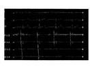
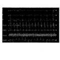
好ましくは、本発明のケミカルアブレーション装置は、心電図マッピング部をさらに備え、前記心電図マッピング部によってアブレーションの対象組織付近の心電信号及び/または外部からの電気刺激信号の伝導状況が検出される。Preferably, the chemical ablation apparatus of the present invention further includes an electrocardiogram mapping unit, and the electrocardiogram mapping unit detects the conduction state of the electrocardiographic signal and / or the electrical stimulation signal from the outside in the vicinity of the target tissue for ablation.
より好ましくは、前記心電図マッピング部は、マッピング電極と、前記マッピング電極と心電図測定装置を接続するための導線とを含み、前記心電図測定装置によって、アブレーションの対象組織付近の心電信号及び/または外部からの電気刺激信号の伝導状況が検出できる。 Yo Ri Preferably, the ECG mapping unit includes a mapping electrode, and a conductor for connecting the mapping electrode and the electrocardiogram measuring device, by the electrocardiogram measuring device, electrocardiographic signal near the target tissue ablation and / or The conduction status of the electrical stimulation signal from the outside can be detected.
より好ましくは、前記針がクッションから突き出たとき、前記マッピング電極を前記針に接近させるように、前記マッピング電極が前記クッションに設置されている。 More preferably, the mapping electrode is installed on the cushion so that the mapping electrode approaches the needle when the needle protrudes from the cushion .
好ましくは、前記クランプ口部と前記クランプ本体部との間の角度が調節できる。Preferably, the angle between the clamp opening portion and the clamp main body portion can be adjusted.
より好ましくは、前記クランプヘッド部と前記クランプ本体部とは、回転可能なダンパー部によって接続される。More preferably, the clamp head portion and the clamp body portion are connected by a rotatable damper portion.
本発明のもう一つの好ましい実施態様として、前記クランプヘッド部は、伝動装置が備えられた回転部によって前記クランプ本体部に接続され、前記伝動装置が、外力によって前記回転部の運動を制御することができる。In another preferred embodiment of the present invention, the clamp head portion is connected to the clamp main body portion by a rotating portion provided with a transmission device, and the transmission device controls the movement of the rotating portion by an external force. Can be done.
好ましくは、本発明のケミカルアブレーション装置は、プーリーをさらに含み、前記クランプヘッド部の移動に合わせるように、前記プーリーに、前記管路部及び/または前記導線が巻き付かれ、巻き数の増減によって、前記管路及び/または前記導線の前記クランプ本体部における伸縮が調節される。Preferably, the chemical ablation apparatus of the present invention further includes a pulley, and the pipeline portion and / or the lead wire is wound around the pulley so as to match the movement of the clamp head portion, and the number of turns is increased or decreased. , The expansion and contraction of the conduit and / or the lead wire in the clamp body is adjusted.
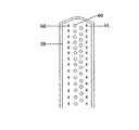
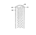
好ましくは、本発明のケミカルアブレーション装置は柵部をさらに含み、前記柵部は、前記クランプ口部における前記注射針穴の両側及び前記クランプ口部の遠端端部に設置され、かつその延びる方向が前記針と一致するように形成される。Preferably, the chemical ablation apparatus of the present invention further includes a fence portion, and the fence portion is installed on both sides of the injection needle hole in the clamp opening portion and at the far end portion of the clamp opening portion, and the extending direction thereof. Is formed so as to coincide with the needle.
具体的には、本発明のケミカルアブレーション装置は、クリッピング部と針部と管路部とを備える。 Specifically, the chemical ablation apparatus of the present invention includes a clipping portion, a needle portion, and a pipeline portion.
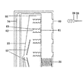
前記クリッピング部は、クランプ本体部と、前記クランプ本体部に取り付けられ、一対のクランプ口部からなるクランプヘッド部とを含み、前記クランプヘッド部とクランプ本体部とは一体化に構成されてもよく、互いに独立して着脱可能に構成されてもよく、前記クランプヘッド部が、前記クランプ口部の相対的な移動によりアブレーションの対象組織を挟んだり緩めたりすることができるように構成され、前記針部は、前記クランプ口部内に取り付けられるものであって、アブレーション試薬注射ヘッド、及びアブレーションの対象組織にアブレーション試薬を注射するための前記アブレーション試薬注射ヘッドに装着された複数の針を含む針部品と、前記針を前記クランプ口部に対して突き出したり収めたりするように制御する針伸縮制御部品とを含み、前記クランプ口部のいずれのうち、もう一つのクランプ口部と対向する側に、前記針の前記クランプ口部の内部への収めと前記クランプ口部から外部への突き出しが可能であるように、注射針穴が設けられており、前記管路部は、アブレーション試薬を移送するために前記針部品と流体的に接続するアブレーション試薬移送管路を含む。 The clipping portion includes a clamp main body portion and a clamp head portion attached to the clamp main body portion and composed of a pair of clamp mouth portions, and the clamp head portion and the clamp main body portion may be integrally configured. , The clamp head portion may be configured to be detachable independently of each other, and the clamp head portion is configured so that the target tissue for ablation can be pinched or loosened by the relative movement of the clamp mouth portion. The portion is attached to the inside of the clamp opening portion, and includes an ablation reagent injection head and a needle component including a plurality of needles attached to the ablation reagent injection head for injecting the ablation reagent into the target tissue for ablation. A needle expansion / contraction control component that controls the needle to protrude or retract with respect to the clamp opening portion is included, and the side of any of the clamp opening portions facing the other clamp opening portion, said. An injection needle hole is provided so that the needle can be stored inside the clamp opening and projected outward from the clamp opening, and the conduit is used to transfer an ablation reagent. Includes an ablation reagent transfer line that fluidly connects to the needle component.
本発明のケミカルアブレーション装置におけるクリッピング部は、クランプ本体部と、クランプ本体部に取り付けられ、一対のクランプ口部(遠側クランプ口部と近側クランプ口部)からなるクランプヘッド部とを含み、クランプヘッド部が、前記クランプ口部の相対的な移動によりアブレーションの対象組織を挟んだり緩めたりすることができるように構成される。 The clipping portion in the chemical ablation apparatus of the present invention includes a clamp main body portion and a clamp head portion attached to the clamp main body portion and composed of a pair of clamp openings (far side clamp opening portion and near side clamp opening portion). The clamp head portion is configured so that the target tissue for ablation can be sandwiched or loosened by the relative movement of the clamp opening portion.
本発明のケミカルアブレーション装置において、近側クランプ口部の内側面(遠側面)に注射針穴が設けられ、遠側クランプ口部の内側面(近側面)に注射針穴が設けられ、針が注射針穴を通じて前記クランプ口部に対して突き出たり収められたりする。近側クランプ口部と遠側クランプ口部とにおける注射針穴が、それぞれ前記アブレーション試薬移送管路の的長軸に沿って同じ間隔で、1列に配列され、または交錯するように2列か多数の列に配列され、つまり、クランプ口部から突き出た針が前記アブレーション試薬移送管路の長軸に沿って同じ間隔で、1列に配列され、または交錯するように2列か多数の列に配列されることができる。これは、ケミカルアブレーションを受けた心筋組織に「割れ目」の発生率を低減か回避させるための設計である。一般的には、隣接する針同士から注射されたケミカルアブレーション試薬による損傷領域は、それぞれちょうど境界が重なり合うのが望ましいが、損傷領域が略球体と想定しているため、配置された針の本数が少ない場合、化学試薬と接触せず、心筋が損傷できなかった「ブラインドスポット」がある恐れがあるので、隣接する2本の針による損傷領域は、所定程度、例えば1〜50%、5〜30%、10〜30%、15〜30%、1−20%、5〜20%、10〜20%などが重なることが好ましい。この観点からすると、場合によって、交錯するように2列か多数の列に配列されることが好ましい。この場合、同列において隣接する2本の針または2列において隣接する針による損傷領域は、重なる範囲が、例えば1〜30%、好ましくは1−20%、5〜20%、10〜20%など少し小さくなってもよい。しかし、交錯するように2列か多数の列に配列されるのは、必ず好ましい構造であるというわけではなく、本発明のケミカルアブレーション装置の最適化や簡素化を図る場合、または、高程度のアブレーションが求められていなく、「割れ目」や「ブラインドスポット」が存在しないだけで十分な場合は、1列の構成を採用し、アブレーション試薬供給装置の流速と圧力を制御することで、治療という目標が達成できる。したがって、上記の例は本発明を制限するものではない。 In the chemical ablation apparatus of the present invention, an injection needle hole is provided on the inner side surface (far side surface) of the near side clamp opening portion, and an injection needle hole is provided on the inner surface (near side surface) of the far side clamp opening portion. It protrudes or fits into the clamp opening through the injection needle hole. Whether the injection needle holes in the near-side clamp port and the far-side clamp port are arranged in one row at the same interval along the target long axis of the ablation reagent transfer pipeline, or in two rows so as to intersect with each other. Arranged in multiple rows, i.e., two or more rows so that the needles protruding from the clamp mouth are arranged in one row at the same spacing along the long axis of the ablation reagent transfer line, or intersect. Can be arranged in. This is designed to reduce or avoid the incidence of "cracks" in chemically ablated myocardial tissue. In general, it is desirable that the boundaries of the damaged areas of the chemical ablation reagent injected from adjacent needles overlap each other, but since the damaged areas are assumed to be approximately spherical, the number of needles arranged is large. If the amount is too small, there may be "blind spots" where the myocardium could not be damaged because it did not come into contact with chemical reagents. %, 10-30%, 15-30%, 1-20%, 5-20%, 10-20% and the like are preferably overlapped. From this point of view, it is preferable that they are arranged in two rows or a large number of rows so as to be interlaced in some cases. In this case, the area of damage caused by two adjacent needles in the same row or adjacent needles in the two rows has an overlapping range of, for example, 1 to 30%, preferably 1 to 20%, 5 to 20%, 10 to 20%, and the like. It may be a little smaller. However, it is not always a preferable structure to arrange them in two rows or a large number of rows so as to intersect with each other, and when optimizing or simplifying the chemical ablation apparatus of the present invention, or to a high degree. If ablation is not required and the absence of "cracks" or "blind spots" is sufficient, the goal of treatment is to adopt a one-row configuration and control the flow velocity and pressure of the ablation reagent supply device. Can be achieved. Therefore, the above example does not limit the present invention.
したがって、近側クランプ口部と遠側クランプ口部における針穴が同じ間隔で1列に配列されている場合、つまり、クランプ口部から突き出た針が同じ間隔で1列に配列されている場合、前記間隔は、隣接する2本の針から注射されたケミカルアブレーション試薬によってそれぞれ組織で形成された損傷領域が、少なくとも1〜40%、好ましくは5〜30%、より好ましくは10〜30%重なるように設けられる。 Therefore, when the needle holes in the near-side clamp opening and the far-side clamp opening are arranged in a row at the same interval, that is, when the needles protruding from the clamp opening are arranged in a row at the same interval. The interval overlaps at least 1-40%, preferably 5-30%, more preferably 10-30% of the damaged areas formed in the tissue by the chemical ablation reagents injected from two adjacent needles, respectively. It is provided as follows.
近側クランプ口部と遠側クランプ口部とにおける針穴がそれぞれ前記管路部の長軸に沿って交錯するように2列に配列されている場合、つまり、クランプ口部から突き出た針が前記管路部の長軸に沿って交錯するように2列に配列されている場合、同じ列において隣接する二つの針の間隔は同じであり、かつ当該列において隣接する二つの針から注射されたケミカルアブレーション試薬によって組織で形成された損傷領域が少なくとも1〜30%、好ましくは5〜20%、より好ましくは10〜20%重なるように設けられる。それに、一方の列における針から、それと隣接する他方の列における針までの間隔は同じであり、かつ前記二つの針から注射されたケミカルアブレーション試薬によって組織で形成された損傷領域が少なくとも1〜30%、5〜20%、より好ましくは10〜20%重なるように設けられる。 When the needle holes in the near side clamp port and the far side clamp port are arranged in two rows so as to intersect along the long axis of the conduit, that is, the needles protruding from the clamp port are arranged in two rows. When arranged in two rows so as to intersect along the long axis of the conduit, the distance between two adjacent needles in the same row is the same, and injection is performed from two adjacent needles in the row. The damaged area formed by the tissue by the chemical ablation reagent is provided so as to overlap at least 1 to 30%, preferably 5 to 20%, and more preferably 10 to 20%. In addition, the distance from the needle in one row to the needle in the other adjacent row is the same, and at least 1-30 damaged areas formed in the tissue by the chemical ablation reagent injected from the two needles. %, 5 to 20%, more preferably 10 to 20%.
近側クランプ口部と遠側クランプ口部とにおける注射針がそれぞれ前記管路システムの長軸にそって交錯するように多数の列に配列されている場合、つまり、クランプ口部から突き出た針が前記管路部の長軸に沿って交錯するように多数の列に配列されている場合、同じ列で隣接する二つの針の間隔は同じであり、かつ当該列において隣接する二つの針から注射されたケミカルアブレーション試薬によって組織で形成された損傷領域が少なくとも1〜30%、好ましくは5〜20%、より好ましくは10〜20%重なるように設けられる。それに、1列における針と隣接する列における隣接する針との間隔は同じであり、かつ前記二つの針から注射されたケミカルアブレーション試薬によって組織で形成された損傷領域が少なくとも1〜30%、5〜20%、より好ましくは10〜20%重なるように設けられる。 When the injection needles at the near side clamp mouth and the far side clamp mouth are arranged in a large number of rows so as to intersect along the long axis of the conduit system, that is, the needles protruding from the clamp mouth. Are arranged in a large number of rows so as to intersect along the long axis of the conduit, the distance between two adjacent needles in the same row is the same, and from two adjacent needles in the row. The damaged area formed by the tissue by the injected chemical ablation reagent is provided to overlap at least 1-30%, preferably 5-20%, more preferably 10-20%. In addition, the distance between the needles in one row and the adjacent needles in the adjacent row is the same, and at least 1-30% of the damaged area formed by the tissue by the chemical ablation reagent injected from the two needles, 5 It is provided so as to overlap by ~ 20%, more preferably 10 to 20%.
好ましい一実施形態において、近側クランプ口部と遠側クランプ口部とにおける各注射針穴の周囲に、クランプ口部に設置され、スプレー管路と吸引管路とそれぞれ接続されるスプレー小穴と吸引小穴とを備えるスプレーシステムと吸引システムとを設置してもよい。例えば、スプレー小穴から生理食塩水をスプレーし、吸引小穴が負圧によって付近の液体を吸引することにより、針によるケミカルアブレーション試薬の注射時に、ケミカルアブレーション試薬が漏れた場合、速やかに生理食塩水によって希釈され、吸引システムによって吸引されることが可能なため、周囲の心筋組織を損傷させることがない。 In a preferred embodiment, a small spray hole and suction are provided at the clamp port and connected to the spray line and the suction line, respectively, around each injection needle hole in the near side clamp port and the far side clamp port. A spray system with small holes and a suction system may be installed. For example, by spraying physiological saline from the spray small hole and sucking the nearby liquid by the suction small hole by negative pressure, if the chemical ablation reagent leaks when the chemical ablation reagent is injected with a needle, the saline solution is used immediately. It is diluted and can be aspirated by the aspiration system without damaging the surrounding myocardial tissue.
好ましい一実施形態において、遠側クランプ口部は固定されており、近側クランプ口部は遠側クランプ口部にスライドすることができる。また、スライドは、前記ケミカルアブレーション装置の遠端に押し棒を押すことによって実現可能である。 In one preferred embodiment, the far side clamp port is fixed and the near side clamp port can slide to the far side clamp port. Further, the slide can be realized by pushing a push rod to the far end of the chemical ablation device.
もう一つの好ましい実施形態において、近側クランプ口部は固定されており、遠側クランプ口部は近側クランプ口部にスライドすることができる。また、スライドは前記ケミカルアブレーション装置の近側に押し棒を引くことによって実現可能である。 In another preferred embodiment, the near clamp port is fixed and the far clamp port can slide to the near clamp port. Further, the slide can be realized by pulling a push rod near the chemical ablation device.
もう一つの好ましい実施形態において、両側のクランプ口部はいずれも、互いに近付いたり離れたりするように、スライドすることができる。また、スライドは、前記ケミカルアブレーション装置の押し棒によって実現可能である。 In another preferred embodiment, the clamp openings on both sides can all slide closer to and away from each other. Further, the slide can be realized by the push rod of the chemical ablation device.
もう一つの好ましい実施形態において、近側クランプ口部と遠側クランプ口部は、いずれも弧度が一致するまたは当てはまる弧状に形成される。このように構成すれば、二つのクランプ口部が接触するまたは近付く際、アブレーションが必要な組織を挟むことができる。 In another preferred embodiment, the near-side clamp port and the far-side clamp port are both formed in an arc shape with matching or matching radians. With this configuration, when the two clamp openings come into contact with each other or come close to each other, the tissue requiring ablation can be sandwiched.
クランプ口部の相対的な移動は、公知の技術によって制御することができる。例えば、クランプ本体部、クランプ柄部及び押し棒によって前記クランプ口部の相対的な移動を制御してもよく、その他公知の技術によってクランプ口部の移動を制御してもよい。 The relative movement of the clamp opening can be controlled by known techniques. For example, the relative movement of the clamp opening portion may be controlled by the clamp main body portion, the clamp handle portion and the push rod, or the movement of the clamp opening portion may be controlled by other known techniques.
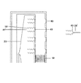
好ましい一実施形態において、両側のクランプ口部の移動と閉合は、クランプ柄部に閉合ロック装置と弾性部品(ばねなどとすることができる)を設置して、前記押し棒がクランプ柄部の近端で閉合ロック装置に接続しクランプ柄部の遠端で弾性部品に接続することによって、実現される。クランプ本体部内は、それぞれ一つのクランプ口部と接続する内軸と内溝部とを含む。この実施形態において、押し棒の移動によって、内軸が内溝部内を移動するように押され、さらに近側クランプ口部が固定された遠側クランプ口部にスライドするように押されることになる(もう一つの実施形態において、近側クランプ口部は固定され、内溝部が移動するように引かれることができ、更に遠側クランプ口部が固定された近側クランプ口部にスライドするように引かれる、または、両側のクランプ口部はいずれもスライドすることができるように構成される。以下の説明においては、特に説明しない限り、遠側クランプ口部が移動するように引かれる実施態様と両側のクランプ口部はいずれもスライドする実施態様とも含まれる)。押し棒がクランプ柄部内で所定距離を移動した後、前記閉合ロック装置は、押し棒を移動できないようにロックすることによって、遠側クランプ口部と近側クランプ口部との間の距離を固定する。ロックされた閉合ロック装置が解除されると、押し棒が弾性部品の弾性回復力によって初期位置に戻されて、遠側と近側クランプ口部とが離れることになる。また、この実施形態において、異なるアブレーション組織の厚さに適するように、押し棒の移動距離は、前記閉合ロック装置によって、複数のプリセット距離に設定される (即ち、押し棒がプリセット距離を移動したら、閉合ロック装置が自動的にロックされる)ことができる。なお、下記説明のあるように、当該移動距離は、近側クランプ口部と遠側クランプ口部から突き出た針が触れない、または両側のクランプ口部における柵部が触れないように、距離をプリセットしてもよい。押し棒の移動距離はもちろん操作者が手動で制御してもよい。 In a preferred embodiment, for the movement and closing of the clamp openings on both sides, a closing lock device and an elastic component (which may be a spring or the like) are installed on the clamp handle, and the push rod is close to the clamp handle. This is achieved by connecting to the closure lock device at the end and to the elastic component at the far end of the clamp handle. The inside of the clamp main body includes an inner shaft and an inner groove portion that are connected to one clamp port portion, respectively. In this embodiment, the movement of the push rod pushes the inner shaft so as to move in the inner groove portion, and further pushes the near side clamp opening portion so as to slide to the fixed far side clamp opening portion. (In another embodiment, the near clamp port is fixed, the inner groove can be pulled to move, and the far side clamp port slides to the fixed near clamp port. Both the clamp openings on both sides are configured to be slidable. In the following description, unless otherwise specified, the embodiment in which the far side clamp openings are pulled so as to move. The clamp openings on both sides are also included in the sliding embodiment). After the push rod has moved a predetermined distance within the clamp handle, the closing lock device locks the push rod so that it cannot move, thereby fixing the distance between the far side clamp port and the near side clamp port. do. When the locked closing lock device is released, the push rod is returned to the initial position by the elastic recovery force of the elastic component, and the far side and the near side clamp opening portion are separated from each other. Also, in this embodiment, the movement distance of the push rod is set to a plurality of preset distances by the closing lock device so as to be suitable for different ablation structure thicknesses (that is, once the push rod has moved the preset distance). , The closing lock device can be locked automatically). As described below, the moving distance is set so that the needles protruding from the near-side clamp opening and the far-side clamp opening do not touch, or the fences at the clamp openings on both sides do not touch. You may preset it. Of course, the moving distance of the push rod may be manually controlled by the operator.
両側のクランプ口部の移動と閉合は、上記に限られない様々な手段によって実現してもよい。例えば、クランプ本体部内に、それぞれ二つのクランプ口部に接続される2本の内軸があって、押し棒によって両側のクランプ口部を異なる間隔となるように相対的に移動させることができる。または、クランプ本体部内に、二つのクランプ口部と接続される1本の内軸があって、押し棒によって二つのクランプ口部を所定の相対距離となるように移動させるなどのように構成されても良い。また、クランプ柄部内に閉合ロック装置と弾性部品を設置しなく、手動で押すことによって二つのクランプ口部を所定の相対距離で固定するように移動させてもよい。 The movement and closing of the clamp openings on both sides may be realized by various means not limited to the above. For example, in the clamp main body, there are two inner shafts each connected to two clamp openings, and the clamp openings on both sides can be relatively moved at different intervals by a push rod. Alternatively, there is one inner shaft connected to the two clamp openings in the clamp main body, and the two clamp openings are moved by a push rod so as to have a predetermined relative distance. You may. Further, the closing lock device and the elastic component may not be installed in the clamp handle portion, and the two clamp mouth portions may be moved so as to be fixed at a predetermined relative distance by manually pushing the clamp handle portion.
上記実施形態において、閉合ロック装置は、例えばスナップフィット構造、ギヤロック機構など、当業者に熟知される種々の閉合ロック部、組立部品または構造であってもよく、押し棒の位置と移動をロックできれば、特に限定されない。 In the above embodiment, the closing lock device may be various closing lock portions, assembly parts or structures familiar to those skilled in the art, such as a snap-fit structure and a gear lock mechanism, as long as the position and movement of the push rod can be locked. , Not particularly limited.
本発明の好ましい一実施態様として、本発明のケミカルアブレーション装置は、クランプヘッド部とクランプ本体部との角度が調節できる。これにより、体内で操作される際、クランプ口部がより望ましい角度でアブレーションの対象組織を挟み、より望ましいアブレーションラインを形成させることが容易になる。例えば、クランプヘッド部とクランプ本体部は、回転可能なダンパー部によって接続され、当該ダンパー部がクランプヘッド部とクランプ本体部との間で所定の角度が保持されるように外力で回転することができ、それに、ロータリーダンパー部自体のダンピングによって、本発明のケミカルアブレーション装置によるクリッピングとアブレーションが行われる際に、この角度が変化しない。前記ロータリーダンパー部は、例えば、ダンパーシャフトであってもよい。あるいは、クランプヘッド部は伝動装置が備えられた回転部によって前記クランプ本体部に接続され、前記伝動装置がクランプヘッド部とクランプ本体部との間で所定の角度が保持されるように外力で前記回転部の運動を制御することができ、当該角度は、本発明のケミカルアブレーション装置によるクリッピングとアブレーションが行われる際に変化しない。前記回転部は、例えばヒンジであってもよい。前記伝動装置は、トラクションロープ、トラクションねじ棒などの伝動装置であってもよい。 As a preferred embodiment of the present invention, the chemical ablation apparatus of the present invention can adjust the angle between the clamp head portion and the clamp main body portion. This facilitates the clamp mouth portion to sandwich the target tissue for ablation at a more desirable angle and form a more desirable ablation line when operated in the body. For example, the clamp head portion and the clamp main body portion are connected by a rotatable damper portion, and the damper portion can be rotated by an external force so that a predetermined angle is maintained between the clamp head portion and the clamp main body portion. In addition, the damping of the rotary damper portion itself does not change this angle when clipping and ablation are performed by the chemical ablation apparatus of the present invention. The rotary damper portion may be, for example, a damper shaft. Alternatively, the clamp head portion is connected to the clamp main body portion by a rotating portion provided with a transmission device, and the transmission device is subjected to an external force so that a predetermined angle is maintained between the clamp head portion and the clamp main body portion. The motion of the rotating part can be controlled, and the angle does not change when clipping and ablation are performed by the chemical ablation apparatus of the present invention. The rotating portion may be, for example, a hinge. The transmission device may be a transmission device such as a traction rope or a traction screw rod.
本発明のケミカルアブレーション装置は、クランプヘッド部とクランプ本体部との角度が0〜180°であってもよく、好ましくは110〜150°である(つまり、クランプヘッド部のクランプ本体部との接続点からその最遠端までの線と、クランプ本体部の縦軸との間の角度)。 In the chemical ablation apparatus of the present invention, the angle between the clamp head portion and the clamp main body portion may be 0 to 180 °, preferably 110 to 150 ° (that is, the connection of the clamp head portion with the clamp main body portion). The angle between the line from the point to its farthest end and the vertical axis of the clamp body).
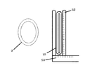
本発明のケミカルアブレーション装置の管路部は、アブレーション試薬を移送するために前記針部品と流体的に接続するアブレーション試薬移送管路を含む。前記アブレーション試薬移送管路によって、前記アブレーション試薬注射ヘッドと前記アブレーション試薬供給装置とが接続される。前記アブレーション試薬移送管路は、近側クランプ口部まで延び、近端がアブレーション試薬供給装置と接続し、遠端が近側クランプ口部の遠端まで直接に到達する第1管路と、遠側クランプ口部まで延び、近端がアブレーション試薬供給装置と接続し、遠端が遠側クランプ口部の遠端まで直接に到達する第2管路と、を含む。 The pipeline portion of the chemical ablation apparatus of the present invention includes an ablation reagent transfer pipeline that fluidly connects to the needle component for transferring the ablation reagent. The ablation reagent transfer conduit connects the ablation reagent injection head and the ablation reagent supply device. The ablation reagent transfer line extends to the near end of the clamp port, the near end is connected to the ablation reagent supply device, and the far end directly reaches the far end of the near end of the clamp port. Includes a second conduit that extends to the side clamp opening, the near end connecting to the ablation reagent supply device, and the far end directly reaching the far end of the far side clamp opening.
好ましい一実施形態において、第1管路と第2管路は、クランプ柄部内で1本のメイン管路となり、前記メイン管路がクランプ柄部から通り抜け、クランプ柄部内またはクランプ柄部外でアブレーション試薬供給装置と接続する。前記第1管路と第2管路は、クランプ柄部内またはクランプ柄部外でそれぞれ異なるアブレーション試薬供給装置と接続してもよい。このように構成すれば、異なる流速と圧力で同じ若しくは異なるケミカルアブレーション試薬を供給することができる。 In a preferred embodiment, the first and second conduits become one main conduit within the clamp handle, the main conduit passing through the clamp handle and ablation inside or outside the clamp handle. Connect with the reagent supply device. The first pipe line and the second pipe line may be connected to different ablation reagent supply devices inside the clamp handle portion or outside the clamp handle portion. With this configuration, the same or different chemical ablation reagents can be supplied at different flow rates and pressures.
もう一つの好ましい実施形態において、第1管路と第2管路において、異なる種類若しくは量のケミカルアブレーション試薬が流れる。このように構成すれば、異なる部位に対して効果の異なるアブレーションが実施される。 In another preferred embodiment, different types or amounts of chemical ablation reagents flow in the first and second conduits. With this configuration, ablation with different effects is performed on different sites.
本発明のケミカルアブレーション装置において、第1管路と第2管路は、ケミカルアブレーション試薬に耐えうる、適切な耐薬品性、耐腐食性を有する材料を採用して製造することができる。前記材料は、所定の柔軟性と硬度を有するべきである。これにより製造された管路は、アブレーション装置内で屈曲、巻曲、移動しやすいように所定の柔軟度を有するとともに、アブレーション装置内のほかの金属やリジッド部に押圧されても凹むことがなく、液体がスムーズに流れることができなくなって管路内の圧力が不均衡となることによって、針から液体が出にくくなったり、足りなかったり、各針から出た液量にバラツキがあったりすることも回避されるように、所定の硬度を有する。管路材料として、耐久性を有し、繰り返し使用に好適であるものが好ましい。前記管路の材料は直接に人体と接触しないが、生体適合性材料であることがさらに好ましい。本発明の好適な管路材料として、ポリ塩化ビニル、ポリウレタン、ポリエチレン、アクリロニトリルブタジエンスチレン共重合体(ABS)などが挙げられるが、上記要求を満たすものであれば、特に限定されない。当業者は、ほかの化学分野や、医療用材料分野に関する技術常識に基づいて、本発明の管路の製造に好適な材料を選択することができる。 In the chemical ablation apparatus of the present invention, the first pipe and the second pipe can be manufactured by using a material having appropriate chemical resistance and corrosion resistance that can withstand the chemical ablation reagent. The material should have the desired flexibility and hardness. The pipeline manufactured by this has a predetermined flexibility so that it can be easily bent, wound, and moved in the ablation device, and does not dent even when pressed by other metal or a rigid portion in the ablation device. , The liquid cannot flow smoothly and the pressure in the pipeline becomes imbalanced, which makes it difficult for the liquid to come out from the needles, is insufficient, or the amount of liquid that comes out from each needle varies. It also has a predetermined hardness so that it can be avoided. As the pipeline material, a material having durability and suitable for repeated use is preferable. The material of the pipeline does not come into direct contact with the human body, but is more preferably a biocompatible material. Suitable pipeline materials of the present invention include polyvinyl chloride, polyurethane, polyethylene, acrylonitrile-butadiene-styrene copolymer (ABS), and the like, but are not particularly limited as long as they satisfy the above requirements. One of ordinary skill in the art can select a material suitable for producing the pipeline of the present invention based on the common general technical knowledge regarding other fields of chemistry and medical materials.
好ましい一実施形態において、アブレーション試薬を各針に供給する際に、各針間の圧力差を可能な限り減少させ、アブレーション試薬を各針に均一に供給するために、アブレーション試薬移送管路は、前記アブレーション試薬注射ヘッドと接続した側がだんだん拡大するようになる。各針間の圧力差をさらに減少させるために、管路の拡大した部分において、例えば分流板などの分流装置を設置してもよい。 In a preferred embodiment, when the ablation reagent is supplied to each needle, the ablation reagent transfer line is used to reduce the pressure difference between the needles as much as possible and to supply the ablation reagent uniformly to each needle. The side connected to the ablation reagent injection head gradually expands. In order to further reduce the pressure difference between the needles, a diversion device such as a diversion plate may be installed in the expanded portion of the pipeline.
もう一つの好ましい実施形態において、各針間の圧力差を減少させるために、前記針のいずれに対しては、少なくとも前記アブレーション試薬移送管路の前記針に近い側に独立管路が配置されており、各管路がそれぞれ1本または多数本の前記針に対する供給を行う。また、異なる針に対して、異なる量若しくは異なる種類のアブレーション試薬を供給しても良く、異なる針に対してアブレーション試薬を供給するか供給しないかを選択するようにしてもいい。 In another preferred embodiment, for any of the needles, an independent line is arranged at least closer to the needle in the ablation reagent transfer line to reduce the pressure difference between the needles. Each conduit supplies one or more of the needles. Further, different amounts or different types of ablation reagents may be supplied to different needles, and it may be selected whether or not to supply the ablation reagents to different needles.
体内において、心臓の周囲に複数の隣接している器官が存在し、心臓の外面には心膜が貼り付いている。実際操作の中で、アブレーション装置がアブレーションの対象部位にセットし、当該部位を挟む過程において、アブレーション装置における針によって周囲の組織、ひいては心房または肺静脈壁が損傷を受けて出血する恐れがある。したがって、本発明のケミカルアブレーション装置の針は、伸縮可能なものであることが好ましく、ケミカルアブレーション装置が体内に入りアブレーションの対象組織にセットされ、当該組織を挟む過程において、針がクランプ口部内部に収められる状態であるが、アブレーション組織を確実に挟んだ後、針を突き出し対象心筋組織内に刺入させ、ケミカルアブレーション媒質を送り出すように制御することができる。また、針の伸縮は、様々な手段によって実現することができ、その手段としては、例えば気圧による制御、液圧による制御、電子機械による制御などが挙げられるが、これらに限らない。 In the body, there are multiple adjacent organs around the heart, and the pericardium is attached to the outer surface of the heart. In the actual operation, the ablation device sets the target site for ablation, and in the process of pinching the site, the needle in the ablation device may damage the surrounding tissue, and thus the atrium or the pulmonary vein wall, and cause bleeding. Therefore, the needle of the chemical ablation device of the present invention is preferably stretchable, and the needle enters the body and is set in the target tissue for ablation, and the needle is inside the clamp mouth in the process of sandwiching the tissue. After the ablation tissue is securely sandwiched, the needle can be pushed out and inserted into the target myocardial tissue to control the chemical ablation medium to be sent out. Further, the expansion and contraction of the needle can be realized by various means, and examples thereof include, but are not limited to, control by atmospheric pressure, control by hydraulic pressure, and control by an electronic machine.
本発明のケミカルアブレーション装置の好ましい一実施態様として、本発明のケミカルアブレーション装置の針伸縮制御部品は、気圧または液圧によって前記針を前記クランプ口部に対して突き出したり収めたりするように制御し、前記針伸縮制御部品は、前記アブレーション試薬注射ヘッドの前記注射針穴から離れた側に設置されたエアバッグまたは液体バッグと、前記アブレーション試薬注射ヘッドと前記注射針穴との間に設置された弾性部と、を含み、前記エアバッグまたは液体バッグは、気体または液体の充填・放出によって体積を変え、前記アブレーション試薬注射ヘッドを前記注射針穴に近付くか離れる方向に移動させ、前記弾性部の弾性は、前記アブレーション試薬注射ヘッドを前記注射針穴から離れる方向に移動させる傾向がある。例えば、クランプ口部内で、アブレーション試薬注射ヘッドの前記注射針穴と離れた側にエアバッグが設置され、前記アブレーション試薬注射ヘッドと前記注射針穴との間に一つ若しくは複数の弾性部が設置されてもよく、エアバッグが送気管によってケミカルアブレーション装置外のバルブに接続され、バルブが送気設備、例えばゴム球に接続され、エアバッグと弾性部との間で管路部と針部品とがセットされる。バルブを開くと、エアバッグ内の気体が排出され、圧力及びエアバッグの体積が減少し、弾性部品が弾性回復力によって針をクランプ口部内部に押し込む。バルブを閉じ、エアバッグ内に充気すると、エアバッグの体積が大きくなり、エアバッグ内の気体の圧力が弾性部品の弾性回復力を上回ると、アブレーション試薬注射ヘッドを、針がクランプ口部から突き出て所定長さが心筋組織内に刺入するまで推し進めることができる。また、液圧装置による針伸縮の制御は、前記気圧による制御と類似して、エアバッグを液体バッグに、送気管路を送液管路に、送気設備を送液設備に置き換えて、液圧による制御が行える。針のクランプ口部から突き出た長さは、エアバッグ内に充気された気体の量/液体バッグ内に送液された液体の量、若しくは針の長さによって制御することができる。 As a preferred embodiment of the chemical ablation apparatus of the present invention, the needle expansion / contraction control component of the chemical ablation apparatus of the present invention controls the needle to protrude or retract with respect to the clamp opening portion by atmospheric pressure or hydraulic pressure. The needle expansion / contraction control component is installed between an air bag or a liquid bag installed on the side of the ablation reagent injection head away from the injection needle hole, and between the ablation reagent injection head and the injection needle hole. The air bag or liquid bag includes an elastic portion, and the volume of the air bag or liquid bag is changed by filling / releasing gas or liquid, and the ablation reagent injection head is moved in a direction toward or away from the injection needle hole to move the elastic portion. Elasticity tends to move the ablation reagent injection head away from the needle hole. For example, in the clamp opening, an airbag is installed on the side of the ablation reagent injection head away from the injection needle hole, and one or more elastic portions are installed between the ablation reagent injection head and the injection needle hole. The air bag may be connected to a valve outside the chemical ablation device by an air supply tube, the valve may be connected to an air supply facility, for example a rubber ball, and between the air bag and the elastic part with a conduit and a needle part. Is set. When the valve is opened, the gas in the airbag is expelled, the pressure and the volume of the airbag are reduced, and the elastic part pushes the needle into the clamp opening by the elastic recovery force. When the valve is closed and the inside of the airbag is filled, the volume of the airbag increases, and when the pressure of the gas in the airbag exceeds the elastic recovery force of the elastic part, the ablation reagent injection head is pressed by the needle from the clamp mouth. It can be pushed forward until it protrudes and has a predetermined length inserted into the myocardial tissue. Further, the control of needle expansion and contraction by the hydraulic pressure device is similar to the control by the atmospheric pressure, and the air bag is replaced with a liquid bag, the air supply pipe line is replaced with a liquid supply pipe line, and the air supply equipment is replaced with a liquid supply equipment. It can be controlled by pressure. The length protruding from the clamp opening of the needle can be controlled by the amount of gas filled in the airbag / the amount of liquid sent into the liquid bag, or the length of the needle.
本発明のケミカルアブレーション装置のもう一つの好ましい実施態様として、本発明のケミカルアブレーション装置の針伸縮制御部品は、電子機械によって前記針を前記クランプ口部に対して突き出したり収めたりするように制御することができる。針伸縮制御部品は、例えば、前記アブレーション試薬注射ヘッドと前記注射針穴との間に設置される電磁弾性部、例えば、電磁ばねを含み、電磁弾性部は、導線によって電子制御装置に接続され、電流で前記電磁弾性部の長さを制御することによって、前記アブレーション試薬注射ヘッドを前記注射針穴に対して近付くか離れる方向に移動させる。例えば、電磁弾性部に電流が流れていない場合、針が電磁ばねの弾性回復力によってクランプ口部の内部に押し込まれる。また、電磁弾性部に電流が流れている場合、電磁弾性部が収縮し内部へ向かう引張力が発生し、アブレーション試薬注射ヘッドを注射針穴に近付く方向に、針がクランプ口部から突き出てかつ所定長さが心筋組織内に刺入するまで進める。針のクランプ口部から突き出た長さは、電流の強さ、若しくは針の長さによって制御することができる。 In another preferred embodiment of the chemical ablation apparatus of the present invention, the needle expansion / contraction control component of the chemical ablation apparatus of the present invention controls the needle so as to protrude or retract with respect to the clamp opening portion by an electronic machine. be able to. The needle expansion / contraction control component includes, for example, an electromagnetic elastic portion installed between the ablation reagent injection head and the injection needle hole, for example, an electromagnetic spring, and the electromagnetic elastic portion is connected to the electronic control device by a conducting wire. By controlling the length of the electromagnetically elastic portion with an electric current, the ablation reagent injection head is moved in a direction toward or away from the injection needle hole. For example, when no current is flowing through the electromagnetic elastic portion, the needle is pushed into the clamp opening portion by the elastic recovery force of the electromagnetic spring. In addition, when an electric current is flowing through the electromagnetic elastic part, the electromagnetic elastic part contracts and an inward tensile force is generated, and the needle protrudes from the clamp opening in the direction in which the ablation reagent injection head approaches the injection needle hole. Proceed until the predetermined length is inserted into the myocardial tissue. The length protruding from the clamp opening of the needle can be controlled by the strength of the electric current or the length of the needle.
電子機械による制御のもう一つの好ましい実施形態として、本発明のケミカルアブレーション装置の針伸縮制御部品は、前記クランプ口部内に設置されたモータを含む。前記モータは伝動装置、例えば、ねじ棒またはギアによって、前記アブレーション試薬注射ヘッドを前記注射針穴に対して近付くか離れる方向に移動させる。例えば、前記クランプ口部内側面(即ち、クランプ口部の注射針穴がある側)と隣接するクランプ口部側壁にモータを設置し、モータは導線を介して電子制御装置と接続し、前記モータには、ギアが取り付けられており、アブレーション試薬注射ヘッドのモータに近い側に、モータにおけるギアと係合するラックが設置されている。モータが一方向に運転すると、ギアはラックとの係合によってアブレーション試薬注射ヘッドを連動させて注射針穴から離れる方向に移動させて、針をクランプ口部内に収める。また、モータが逆方向に運転すると、ギアはラックとの係合によってアブレーション試薬注射ヘッドを連動させて注射針穴に近付く方向に、針がクランプ口部から突き出てかつ所定長さが心筋組織内に刺入するまで進める。針のクランプ口部から突き出た長さは、モータの運転時間、ラックの長さ若しくは針の長さによって制御することができる。または、前記クランプ口部内側面(即ちクランプ口部の注射針穴がある側)と隣接するクランプ口部側壁にラックを設置し、アブレーション試薬注射ヘッドのラックに近い側にラックと係合するギアを有するモータを設置し、上記実施形態と同様に操作することによっても、針の伸縮に対する制御を実現できる。 As another preferred embodiment of electronic machine control, the needle expansion / contraction control component of the chemical ablation apparatus of the present invention includes a motor installed in the clamp opening. The motor uses a transmission device, such as a screw rod or gear, to move the ablation reagent injection head closer to or further from the needle hole. For example, a motor is installed on the inner side surface of the clamp opening (that is, the side of the clamp opening where the injection needle hole is located) and the side wall of the clamp opening, and the motor is connected to the electronic control device via a conducting wire to the motor. Is fitted with a gear, and a rack that engages the gear in the motor is installed on the side of the ablation reagent injection head near the motor. When the motor operates in one direction, the gear engages with the rack to interlock the ablation reagent injection head and move it away from the injection needle hole to accommodate the needle in the clamp opening. In addition, when the motor operates in the opposite direction, the gear engages with the rack to interlock the ablation reagent injection head and approach the injection needle hole. Proceed until it pierces. The length protruding from the clamp opening of the needle can be controlled by the operating time of the motor, the length of the rack, or the length of the needle. Alternatively, a rack is installed on the inner side surface of the clamp opening (that is, the side of the clamp opening where the injection needle hole is located) and the side wall of the clamp opening, and a gear that engages with the rack is placed on the side of the ablation reagent injection head near the rack. Control against expansion and contraction of the needle can also be realized by installing the motor and operating it in the same manner as in the above embodiment.
電子機械による制御のもう一つの好ましい実施形態として、アブレーション試薬注射ヘッドのクランプ口部側壁に近い側にリニアステッピングモータを設置し、モータは導線を介して電子制御装置に接続され、前記リニアステッピングモータのねじ棒がクランプ口部側壁に設置されている。モータが一方向に運転すると、アブレーション試薬注射ヘッドを連動させて注射針穴から離れる方向に移動させることができ、これにより針がクランプ口部内に収められる。また、モータが逆方向に運転すると、アブレーション試薬注射ヘッドを連動させて注射針穴に近付く方向に、針がクランプ口部から突き出てかつ所定長さが心筋組織内に刺入するまで進めることができる。針のクランプ口部から突き出た長さは、モータの運転時間、ねじ棒の長さ若しくは針の長さによって制御することができる。または、アブレーション試薬注射ヘッドのクランプ口部側壁に近い側にねじ棒を設置し、クランプ口部側壁にモータを設置することによっても、同様に針の伸縮に対する制御を実現できる。 As another preferred embodiment of electronic mechanical control, a linear stepping motor is installed on the side of the ablation reagent injection head near the side wall of the clamp opening, and the motor is connected to the electronic control device via a lead wire to be connected to the linear stepping motor. The screw rod is installed on the side wall of the clamp opening. When the motor operates in one direction, the ablation reagent injection head can be interlocked and moved away from the injection needle hole, whereby the needle is housed in the clamp opening. In addition, when the motor operates in the opposite direction, the ablation reagent injection head is interlocked to advance in the direction of approaching the injection needle hole until the needle protrudes from the clamp opening and the predetermined length is inserted into the myocardial tissue. can. The length protruding from the clamp opening of the needle can be controlled by the operating time of the motor, the length of the screw rod, or the length of the needle. Alternatively, by installing a screw rod on the side of the ablation reagent injection head near the side wall of the clamp opening and installing a motor on the side wall of the clamp opening, control with respect to expansion and contraction of the needle can be similarly realized.
本発明のケミカルアブレーション装置は針の伸縮に対する制御として、ほかの手段を採用してもよい。したがって、上記の例は本発明を制限するものではない。 The chemical ablation apparatus of the present invention may employ other means as a control for expansion and contraction of the needle. Therefore, the above example does not limit the present invention.
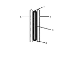
本発明のもう一つの好ましい実施形態として、本発明のケミカルアブレーション装置は、それぞれ両側のアブレーションクランプ口部にセットされる適当な厚さのクッションをさらに含む。前記クッションは前記注射針穴を覆うように構成される。クッションの厚さは、アブレーションクランプ口部における注射針が完全に突き出た場合の長さと比べて等しい、又は略上回るように設定される。このように構成すれば、アブレーションクランプ口部がアブレーションの対象組織をクリッピングし注射針が完全に突き出たとき、クッションは、両側アブレーションクランプ口部と両側アブレーションクランプ口部の間にある組織との押圧によって圧縮され、注射針は、クッションから突き出て、アブレーションの対象組織に刺入することができる。一方、アブレーションクランプ口部の、心筋組織と接触していない部分における注射針は、クッション内に収められているままとなる。この場合、ケミカルアブレーション試薬を注射したら、ケミカルアブレーション試薬の漏れによる周囲の組織の損傷が回避される。 As another preferred embodiment of the invention, the chemical ablation apparatus of the invention further comprises a cushion of appropriate thickness set at the ablation clamp openings on both sides, respectively. The cushion is configured to cover the injection needle hole. The thickness of the cushion is set to be equal to or substantially greater than the length of the injection needle at the mouth of the ablation clamp when it is fully protruded. With this configuration, when the ablation clamp mouth clips the target tissue for ablation and the injection needle completely protrudes, the cushion presses against the tissue between the bilateral ablation clamp mouth and the bilateral ablation clamp mouth. Compressed by, the needle can protrude from the cushion and pierce the target tissue for ablation. On the other hand, the injection needle in the portion of the ablation clamp mouth that is not in contact with the myocardial tissue remains contained in the cushion. In this case, if the chemical ablation reagent is injected, damage to the surrounding tissue due to leakage of the chemical ablation reagent is avoided.
アブレーションクランプ口部における注射針は伸縮不可な場合、即ち、本発明のケミカルアブレーション装置は前記針伸縮制御部品を備えない場合、本発明は、両側のクランプ口部に、圧縮・回復が可能なクッションを設置することによって、アブレーションクランプの注射針による周囲の組織の損傷を回避することもできる。この場合、クッションは、完全にアブレーションクランプ口部における注射針を包み込むことになり、クッションの厚さが注射針の長さに等しく若しくはその長さを略上回るように設定される。このように構成すれば、アブレーションクランプ口部がクリッピングしていないときに、クッションが初期状態にあり、注射針がクッション内にあることになる、これによって、アブレーションクランプを操作する際、アブレーションクランプ口部が体内を移動しながら、注射針が周囲の組織を刺して損傷させることがない。アブレーションクランプ口部がアブレーションの対象組織にセットされ、アブレーションクランプ口部がクリッピングしたとき、クッションは、両側アブレーションクランプ口部と両側アブレーションクランプ口部の間にある組織との押圧によって圧縮され、注射針は、クッションから突き出て、アブレーションの対象組織に刺入する。一方、アブレーションクランプ口部の、心筋組織と接触していない部分における注射針は、クッション内に収められているままとなる。この場合、ケミカルアブレーション試薬を注射したら、アブレーションの対象組織に刺入された針からは、ケミカルアブレーション試薬を送り出せるが、クッション内に収められているままの注射針からは、ケミカルアブレーション試薬を送り出すことができない。これによって、アブレーションクランプヘッド部の両側の、心筋組織に刺入できなかった針が、心膜または縦隔隙間内にはみ出し、ケミカルアブレーション試薬の注射時に比較的な低圧領域に位置するために生じた、一部のケミカルアブレーション試薬の漏れや、アブレーションの対象領域に対する化学試薬の送出量の降下、周囲組織の損傷が、回避される。アブレーション完了後、両側のクランプ口部が離れることになり、両側のクランプ口部と心筋組織による押圧もなくなるため、クッションが初期状態に戻り、注射針がクッション内に完全に収められるようになるため、アブレーションクランプの操作時に、アブレーションクランプ口部が体内を移動しながら、注射針が周囲の組織を損傷させることがない。 When the injection needle at the ablation clamp opening cannot be expanded or contracted, that is, when the chemical ablation device of the present invention does not include the needle expansion / contraction control component, the present invention has a cushion capable of compressing and recovering at the clamp openings on both sides. It is also possible to avoid damage to the surrounding tissue by the injection needle of the ablation clamp. In this case, the cushion will completely wrap the injection needle at the mouth of the ablation clamp, and the thickness of the cushion will be set to be equal to or substantially greater than the length of the injection needle. With this configuration, when the ablation clamp opening is not clipping, the cushion is in the initial state and the injection needle is in the cushion, so that when operating the ablation clamp, the ablation clamp opening As the part moves through the body, the needle does not pierce and damage the surrounding tissue. When the ablation clamp port is set on the target tissue for ablation and the ablation clamp port is clipped, the cushion is compressed by pressing against the tissue between the bilateral ablation clamp port and the bilateral ablation clamp port, and the injection needle Sticks out of the cushion and pierces the target tissue for ablation. On the other hand, the injection needle in the portion of the ablation clamp mouth that is not in contact with the myocardial tissue remains contained in the cushion. In this case, after injecting the chemical ablation reagent, the chemical ablation reagent can be sent out from the needle inserted into the target tissue for ablation, but the chemical ablation reagent is sent out from the injection needle still contained in the cushion. Can't. This caused the needles on both sides of the ablation clamp head that could not penetrate the myocardial tissue to protrude into the pericardium or interstitial space and be located in a comparatively low pressure region when the chemical ablation reagent was injected. , Leakage of some chemical ablation reagents, decrease in the amount of chemical reagents delivered to the target area of ablation, and damage to surrounding tissues are avoided. After the ablation is completed, the clamp openings on both sides will be separated, and there will be no pressure from the clamp openings on both sides and the myocardial tissue, so the cushion will return to the initial state and the injection needle will be completely contained in the cushion. When operating the ablation clamp, the injection needle does not damage the surrounding tissue while the ablation clamp mouth moves inside the body.
クッションの材質として、毒性がない、化学的不活性を示す、病原性がない、近くの組織を損傷させない、アレルギーを起こさないなどの性質を有するものでなければならない。よって、例えば精製した天然ゴム、シリコーンゴム、ポリウレタンなどの上記特性を有するものを採用することができる。 The material of the cushion must be non-toxic, chemically inactive, non-pathogenic, non-damaging to nearby tissues, non-allergenic, etc. Therefore, for example, purified natural rubber, silicone rubber, polyurethane, or the like having the above-mentioned characteristics can be adopted.
本発明のケミカルアブレーション装置において、近側クランプ口部と遠側クランプ口部から突き出た針は、矢状面においてそれぞれ第1管路若しくは第2管路の軸線との夾角が30〜150°であり、好ましくは90°である(即ち、垂直)。 In the chemical ablation apparatus of the present invention, the needles protruding from the near-side clamp port and the far-side clamp port have an angle of 30 to 150 ° with respect to the axis of the first or second conduit in the sagittal plane, respectively. Yes, preferably 90 ° (ie, vertical).
一実施形態において、近側クランプ口部から突き出た針は、その矢状面において第1 管路の軸線との夾角が30〜90°であり、遠側クランプ口部から突き出た針は、その矢状面において第2管路の軸線との夾角が90〜150°である。或いは、遠側クランプ口部から突き出た針は、その矢状面において第2管路の軸線との夾角が30〜90°であり、近側クランプ口部から突き出た針は、その矢状面において第1管路の軸線との夾角が90〜150°である。 In one embodiment, the needle protruding from the near clamp port has an angle of 30 to 90 ° with respect to the axis of the first pipeline in the sagittal plane, and the needle protruding from the far clamp port has its sagittal plane. The sagittal plane has an angle of 90 to 150 ° with respect to the axis of the second pipeline. Alternatively, the needle protruding from the far side clamp mouth has a sagittal plane having an angle of 30 to 90 ° with respect to the axis of the second pipeline, and the needle protruding from the near side clamp mouth has the sagittal plane. The angle of deviation from the axis of the first pipeline is 90 to 150 °.
心臓の大きさ、形が人によって少し異なり、不整脈の種類によって治療に用いられる対象となるアブレーションラインも異なるので、同じ規格のアブレーション装置が使用され、針の本数、配列長さ、配列密度が同じである場合、針の配列長さが限られているため、一部のアブレーションの対象組織は針が刺入されず、ケミカルアブレーション試薬と接触できないことによって、「割れ目」が生じてしまい、又は、針の配列が長すぎるため、アブレーションを行う必要がない一部の組織もケミカルアブレーション試薬と接触したことによって、組織が壊死してしまい、そして、針の配列が長すぎるため、一部の針が心筋組織に刺入できず、心膜腔内にはみ出すことになり、管路部にケミカルアブレーション試薬が注入される際に、心筋組織に刺入されなかった針の圧力が比較的に低いため、一部のケミカルアブレーション試薬がこれらの針から排出され、アブレーション効果に影響が出るほか、排出されたケミカルアブレーション試薬によって周囲の組織を損傷させる恐れもある。したがって、本アブレーションクランプの針は、針キャップ付きとなるように設けられてもよく、着脱可能に設けられてもよい。術前に、左房及び肺静脈の造影CTまたはその他の医用イメージング技術を利用してアブレーションが必要となる肺静脈と心房組織に対してイメージングまたは3次元再構成を行い、コンピューターデータ処理ソフトウェアまたはほかの測定方法によって肺静脈前庭部の矢状面断面の周長を測算し、クリッピングされた肺静脈前庭部の大体の長さを取得して、さらに針の配列長さと本数を確定した後、プレ測定で得られた長さに基づいて、針キャップで使用する必要のない注射針を封止する、ことができる。また、手術中にプレクリッピングを行うことによって正確に測算することもできる。プレクリッピング時に、針がクランプ口部から突き出ず、クランプ口部とクランプ柄部における目盛のそれぞれによってアブレーションが必要な組織の長さ及び所要する針の長さを測定する。または、プレクリッピング後に、クランプ口部の、心筋組織に貼り付いたマッピング電極によって伝送されてきた電気信号の範囲に基づいて、アブレーションが必要な組織の長さの範囲が確定される。 Since the size and shape of the heart differ slightly from person to person, and the ablation line used for treatment differs depending on the type of arrhythmia, the same standard ablation device is used, and the number of needles, array length, and array density are the same. In this case, due to the limited length of the needle arrangement, some ablation target tissues may not be pierced by the needle and may not come into contact with the chemical ablation reagent, resulting in "cracks" or Some tissues that do not need to be ablated because the needle arrangement is too long also come into contact with the chemical ablation reagent, causing tissue necrosis, and the needle arrangement is too long for some needles. Because it cannot penetrate into the myocardial tissue and protrudes into the pericardial space, and when the chemical ablation reagent is injected into the duct, the pressure of the needle that did not penetrate into the myocardial tissue is relatively low. Some chemical ablation reagents are ejected from these needles, affecting the ablation effect and the ejected chemical ablation reagents can damage the surrounding tissue. Therefore, the needle of the ablation clamp may be provided so as to have a needle cap, or may be provided so as to be removable. Preoperatively, imaging or three-dimensional reconstruction of pulmonary veins and atrial tissue requiring ablation using contrast CT or other medical imaging techniques of the left atrium and pulmonary veins, computer data processing software or others The circumference of the sagittal cross section of the pulmonary vein vestibule is calculated by the measurement method of, the approximate length of the clipped pulmonary vein vestibule is obtained, and the arrangement length and the number of needles are further determined, and then the pre Based on the length obtained by the measurement, the injection needle that does not need to be used in the needle cap can be sealed. It can also be accurately measured by performing pre-clipping during surgery. During pre-clipping, the needle does not protrude from the clamp opening, and the length of the tissue that requires ablation and the required needle length are measured by the scales at the clamp opening and the clamp handle, respectively. Alternatively, after preclipping, the range of tissue lengths that require ablation is determined based on the range of electrical signals transmitted by the mapping electrodes attached to the myocardial tissue at the clamp opening.
もう一つの好ましい実施形態において、本発明のケミカルアブレーション装置の針は着脱可能に設けられてもよい。クリッピング必要のある長さが確定された後、その長さに基づいて対応する長さ範囲内で単列または複数列の針を装着するほか、アブレーションが必要とされる心筋組織の厚さによって長さが異なる針を装着することもできる。そのために、アブレーション注射ヘッドには、クランプ口部に設置された注射針穴と平行して対応付けるように単列または複数列の針固定穴を設置することができる。針固定穴は、アブレーション試薬移送管路に接続され、針が装着されていないとき、ケミカルアブレーション試薬が漏れないように封止されることになる。そして、針が装着されたら、針とアブレーション試薬移送管路とが連通される。長さの異なる針が針固定穴に装着後、針先がクランプ口部外にはみ出さないように、針固定穴の深さは、プリセットされた最長の針の長さに等しい若しくはその長さを上回るように設定される。前記針の、前記針固定穴における装着深さは、必要に応じて調節可能である。例えば、針固定穴内で異なる深さで段差部構造を設け、前記針の後部に前記針固定穴の段差部構造の形状に嵌り合った段差部構造を有する。これによって、長さが異なる各針が、それぞれ異なる深さの段差部に固定されるため、注射深さの異なる針が得られるほか、針先がクランプ口部の外部にはみ出すこともない。または、針固定穴内にねじ部を設置し、前記針の後部に前記針固定穴の形状に嵌り合ったねじ部を有する。長さの異なる針が前記針固定穴内に捩じり込まれ、針の捩じり込まれた程度を調節することによって、注射深さの異なる針が得られる。この要求を満たすように上記以外の構成を採用してもよい。したがって、上記の例は本発明を制限するものではない。 In another preferred embodiment, the needle of the chemical ablation apparatus of the present invention may be detachably provided. Once the length that needs clipping is determined, single or multiple rows of needles are attached within the corresponding length range based on that length, as well as the length depending on the thickness of myocardial tissue that requires ablation. It is also possible to attach needles with different lengths. Therefore, the ablation injection head can be provided with a single row or a plurality of rows of needle fixing holes so as to correspond in parallel with the injection needle holes provided in the clamp opening portion. The needle fixing hole is connected to the ablation reagent transfer conduit and is sealed so that the chemical ablation reagent does not leak when the needle is not attached. Then, when the needle is attached, the needle and the ablation reagent transfer line are communicated with each other. The depth of the needle fixing hole is equal to or the length of the preset longest needle so that the needle tip does not protrude outside the clamp opening after the needles of different lengths are attached to the needle fixing hole. Is set to exceed. The mounting depth of the needle in the needle fixing hole can be adjusted as needed. For example, a stepped portion structure is provided in the needle fixing hole at different depths, and the rear portion of the needle has a stepped portion structure that fits the shape of the stepped portion structure of the needle fixing hole. As a result, the needles having different lengths are fixed to the stepped portions having different depths, so that needles having different injection depths can be obtained, and the needle tip does not protrude to the outside of the clamp opening portion. Alternatively, a screw portion is installed in the needle fixing hole, and the rear portion of the needle has a screw portion that fits the shape of the needle fixing hole. Needles having different lengths are screwed into the needle fixing holes, and the degree of screwing of the needles is adjusted to obtain needles having different injection depths. A configuration other than the above may be adopted so as to satisfy this requirement. Therefore, the above example does not limit the present invention.
好ましい一実施形態において、本発明のケミカルアブレーション装置の針は、より多くのアブレーションの対象組織をケミカルアブレーション試薬と接触させるために、先端に穴が一つ設けられる、または、先端に穴が一つ設けられ、側面に側孔が一つ若しくは複数設けられるように構成される。 In a preferred embodiment, the needle of the chemical ablation apparatus of the present invention is provided with one hole at the tip or one hole at the tip in order to bring more tissue to be ablated into contact with the chemical ablation reagent. It is provided so that one or more side holes are provided on the side surface.
注射針がクッションから通り抜け、または心筋組織に刺入した際、クッション若しくは心筋組織により針穴が塞がれることを回避するために、注射針は、通常の注射針、つまり細長い中空円柱状で、遠端の針先部が斜面で鋭角となる形状を採用することができる。一方、注射針がクッションから突き出た、または心筋組織に刺入した際に、クッション若しくは心筋組織により針穴が塞がれることを回避するために、通常の注射針と異なって、遠端の針先の先端が封止されている。先端の下方に、ケミカルアブレーション試薬を心筋組織に注射するための複数の側孔が開放されている。また、注射針でアブレーション試薬を注射する際に、薄い心筋組織が先端の穴から高圧で瞬間的に噴射されてきたアブレーション試薬によって押し破られ、より多いアブレーション試薬がアブレーションの対象組織内に入るのではなく、心腔に入ってしまうが、このような、先端の穴が封止された注射針によって、上記事態が回避される。 In order to prevent the needle hole from being blocked by the cushion or myocardial tissue when the injection needle passes through the cushion or is inserted into the myocardial tissue, the injection needle is a normal injection needle, that is, an elongated hollow columnar shape. It is possible to adopt a shape in which the needle tip portion at the far end has a sharp angle on a slope. On the other hand, unlike a normal injection needle, a far-end needle is used to prevent the needle hole from being blocked by the cushion or myocardial tissue when the injection needle protrudes from the cushion or is inserted into the myocardial tissue. The tip of the tip is sealed. Below the tip, multiple side holes are opened for injecting the chemical ablation reagent into the myocardial tissue. Also, when injecting an ablation reagent with an injection needle, the thin myocardial tissue is crushed by the ablation reagent that is instantaneously ejected from the hole at the tip at high pressure, and more ablation reagent enters the target tissue for ablation. Instead, it enters the heart cavity, but such an injection needle with a sealed tip hole avoids the above situation.
所要するケミカルアブレーション試薬の注入量は、次の計算式によって計算される。ケミカルアブレーション試薬の総注入量=1本の注射針による試薬注入量の閾値×注射針の本数、または試薬注入ポンプを使用した場合、ケミカルアブレーション試薬の注入時間=(1本の注射針による試薬注入量の閾値×注射針の本数)/ 試薬注入速度。前記1本の注射針によって注入される試薬量の閾値は、アブレーションが行われる組織にブラインドスポットがない(つまり、損傷を受けていない組織が存在しない)ように、注射針を球心に、注入されたケミカルアブレーション試薬によるアブレーションのターゲット組織の損傷領域(または体積)と隣接する注射針による損傷領域(または体積)とが重なる(前述の通り)ときの最小値または閾値である。実際の使用において、1本の注射針による試薬注入量は、当該閾値より等しく、または略上回るようにすべきである(一般的には、当該閾値より10〜40%程度大きくなるように制御する)。 The required injection amount of the chemical ablation reagent is calculated by the following formula. Total injection amount of chemical ablation reagent = threshold of injection amount with one injection needle x number of injection needles, or when using a reagent injection pump, injection time of chemical ablation reagent = (injection of reagent with one injection needle) Amount threshold x number of injection needles) / reagent injection rate. The threshold for the amount of reagent injected by the single needle is to inject the needle into the sphere so that there are no blind spots in the ablated tissue (ie, no undamaged tissue). This is the minimum value or threshold value when the damaged area (or volume) of the target tissue for ablation by the chemical ablation reagent and the damaged area (or volume) of the adjacent injection needle overlap (as described above). In actual use, the amount of reagent injected by one needle should be equal to or substantially above the threshold (generally controlled to be about 10-40% greater than the threshold). ).
アブレーション完了後にアブレーションラインが完全であるか否か、割れ目が存在するか否かを検証するために、本発明のケミカルアブレーション装置は、心電図マッピング部をさらに備える。前記心電図マッピング部によってアブレーションの対象組織付近の心電信号及び/または外部からの電気信号刺激の伝導状況を検出することで、アブレーション効果が判断される。前記心電図マッピング部は、マッピング電極と、前記マッピング電極と心電図測定装置を接続するための導線とを含み、前記心電図測定装置は、アブレーションの対象組織付近の心電信号及び/または外部からの電気信号刺激の伝導状況を検出することができる。前記マッピング電極は、前記クランプ口部に設置され、前記注射針穴の近く、例えば、注射針穴の外側若しくは両側(クランプ口部にクッションが設けられた場合、電極がクッションにセットされ、注射針がクッションから突き出たら、電極が前記針に近付くようになる。例えば、電極が注射針の外側か両側に位置し、かつ注射針と平行するように配列される。)に位置する。また、心電図測定装置はプロセッサ、モニタ、ポリグラフ、刺激装置などを備えることができる。前記プロセッサは、ケミカルアブレーション装置内に設けられてもよく、ケミカルアブレーション装置の外部に設けられ、導線でケミカルアブレーション装置と接続するように構成されてもよい。前記モニタは、ケミカルアブレーション装置上(表面)に設置されてもよく、ケミカルアブレーション装置の外部に設けられ、導線でケミカルアブレーション装置と接続するように構成されてもよい。前記ポリグラフと刺激装置は、ケミカルアブレーション装置の外部に設けられ、導線でケミカルアブレーション装置と接続するように構成されることができる。 The chemical ablation apparatus of the present invention further comprises an electrocardiogram mapping unit to verify whether the ablation line is complete and whether cracks are present after the ablation is completed. The ablation effect is determined by detecting the conduction state of the electrocardiographic signal and / or the electrical signal stimulus from the outside in the vicinity of the target tissue for ablation by the electrocardiogram mapping unit. The electrocardiogram mapping unit includes a mapping electrode and a lead wire for connecting the mapping electrode and the electrocardiogram measuring device, and the electrocardiogram measuring device includes an electrocardiographic signal in the vicinity of a target tissue for ablation and / or an electric signal from the outside. The conduction status of the stimulus can be detected. The mapping electrode is installed at the clamp port, and is near the injection needle hole, for example, outside or both sides of the injection needle hole (when a cushion is provided at the clamp port, the electrode is set on the cushion and the injection needle is set. Is located on the outside or both sides of the needle and is arranged parallel to the needle) as the electrode comes closer to the needle as it protrudes from the cushion. In addition, the electrocardiogram measuring device can include a processor, a monitor, a polygraph, a stimulating device, and the like. The processor may be provided inside the chemical ablation apparatus, or may be provided outside the chemical ablation apparatus and configured to be connected to the chemical ablation apparatus by a lead wire. The monitor may be installed on the chemical ablation device (surface), or may be provided outside the chemical ablation device and configured to be connected to the chemical ablation device by a lead wire. The polygraph and the stimulator are provided outside the chemical ablation device and can be configured to be connected to the chemical ablation device by a lead wire.
好ましい一実施形態において、マッピング電極は、クランプ口部の注射針穴の一側に(クランプ口部にクッションが設けられる場合、マッピング電極がクッションに設置され、注射針がクッションから突き出ると、電極が注射針の一側に位置するようになる)等間隔で複数設置され、好ましくは、注射針穴と並んで設置され、そして、導線と接続されている。また、導線は、ケミカルアブレーション装置内部にセットされ、その一端がマッピング電極に接続され、他端がプロセッサに接続される。プロセッサは、アブレーション装置内若しくはアブレーション装置外にセットされ、モニタと接続する。アブレーションの対象組織がクランプヘッド部にクリッピングされると、クランプ口部におけるマッピング電極がアブレーションの対象組織の近くの心外膜に貼り付き、心電信号を導線によってプロセッサに伝導することができる。プロセッサは、予めロードされたプログラムによる簡単な計算によって、アブレーションラインが完全であるか否か、「割れ目」が存在するか否か、及び割れ目の位置について検証できるほか、モニタによってアブレーションの対象組織の心電信号をリアルタイムで表示させて、アブレーションが完全であるか否かが表示される。 In a preferred embodiment, the mapping electrode is located on one side of the injection needle hole of the clamp opening (if the clamp opening is provided with a cushion, the mapping electrode is placed on the cushion and when the injection needle protrudes from the cushion, the electrode is It will be located on one side of the needle) at regular intervals, preferably alongside the needle hole and connected to the lead wire. Further, the conductor is set inside the chemical ablation device, one end thereof is connected to the mapping electrode, and the other end is connected to the processor. The processor is set inside or outside the ablation device and connects to the monitor. When the target tissue for ablation is clipped to the clamp head portion, the mapping electrode at the clamp port portion adheres to the epicardium near the target tissue for ablation, and the electrocardiographic signal can be conducted to the processor by the lead wire. The processor can verify whether the ablation line is complete, whether there are "cracks", and the location of the cracks by a simple calculation by a preloaded program, and the monitor can verify the ablation target tissue. The electrocardiographic signal is displayed in real time to indicate whether the ablation is complete or not.
もう一つの好ましい実施形態において、クランプ口部の注射針穴の両側にマッピング電極(クランプ口部にクッションが設けられる場合、マッピング電極がクッションに設置され、注射針がクッションから突き出ると、電極が注射針の両側に位置するようになる)を等間隔で複数設置され、好ましくは、注射針穴と並んで設置され、そして、導線と接続されている。また、導線は、ケミカルアブレーション装置内部にセットされ、その一端がマッピング電極に接続され、他端がプロセッサに接続される。プロセッサは、アブレーション装置内若しくはアブレーション装置外にセットされ、モニタと接続する。心電図マッピングシステムは、別体の刺激装置と接続してもよい。アブレーションの対象組織がクランプヘッド部にクリッピングされると、クランプ口部におけるマッピング電極がアブレーションの対象組織の近くの心外膜に貼り付き、心電信号を導線によってプロセッサに伝導することができる。プロセッサは、予めロードされたプログラムによる簡単な計算によって、アブレーションラインが完全であるか否か、「割れ目」が存在するか否か、及び割れ目の位置について検証できるほか、モニタによってアブレーションの対象組織の心電信号をリアルタイムで表示させて、アブレーションが完全であるか否かが表示される。また、心電図マッピングシステムとは別体の刺激装置によって、クランプ口部両側のマッピング電極の各々で電気刺激信号を発し、他方のマッピング電極で電気刺激信号がアブレーションの対象組織を経由して伝導できたかどうかをマッピングすることによって、アブレーションラインが連続的かつ完全であるか否か、「割れ目」が存在するか否か、そしてアブレーションの対象組織に両方向性ブロックが完成できたか否かを検証することによって、アブレーションの成否、または再度のアブレーションの必要性が判断される。 In another preferred embodiment, mapping electrodes are placed on both sides of the injection needle hole in the clamp opening (if a cushion is provided in the clamp opening, the mapping electrode is placed in the cushion, and when the injection needle protrudes from the cushion, the electrodes are injected. A plurality of (to be located on both sides of the needle) are installed at equal intervals, preferably alongside the injection needle hole and connected to the lead wire. Further, the conductor is set inside the chemical ablation device, one end thereof is connected to the mapping electrode, and the other end is connected to the processor. The processor is set inside or outside the ablation device and connects to the monitor. The electrocardiogram mapping system may be connected to a separate stimulator. When the target tissue for ablation is clipped to the clamp head portion, the mapping electrode at the clamp port portion adheres to the epicardium near the target tissue for ablation, and the electrocardiographic signal can be conducted to the processor by the lead wire. The processor can verify whether the ablation line is complete, whether there are "cracks", and the location of the cracks by a simple calculation by a preloaded program, and the monitor can verify the ablation target tissue. The electrocardiographic signal is displayed in real time to indicate whether the ablation is complete or not. Also, was the electrical stimulation signal emitted from each of the mapping electrodes on both sides of the clamp opening by a stimulation device separate from the electrocardiogram mapping system, and the electrical stimulation signal was conducted through the target tissue for ablation at the other mapping electrode? By mapping, by verifying whether the ablation lines are continuous and complete, whether there are "cracks", and whether bidirectional blocks have been completed in the target tissue for ablation. , The success or failure of the ablation, or the need for another ablation is determined.
好ましい実施形態として、本発明のケミカルアブレーション装置は、プーリーをさらに含み、前記プーリーに、前記管路部及び/または前記導線が巻き付かれ、巻き数の増減によって、前記管路及び/または前記導線の前記クランプ本体部における伸縮が調節されることで、前記クランプヘッド部の移動に合わせるようになる。本実施形態によるプーリーは、クランプ柄部内に設置されてもよく、クランプ口部の外部に設置されてもよい。 As a preferred embodiment, the chemical ablation apparatus of the present invention further includes a pulley, and the conduit portion and / or the lead wire is wound around the pulley, and the conduit and / or the lead wire is wound by increasing or decreasing the number of turns. By adjusting the expansion and contraction of the clamp main body portion, the movement of the clamp head portion is adjusted. The pulley according to the present embodiment may be installed inside the clamp handle portion or may be installed outside the clamp opening portion.
本発明のケミカルアブレーション装置は、柵部をさらに備えてもよい。前記柵部は、前記近側クランプ口部と遠側クランプ口部における針穴の両側及びクランプ口部の遠端端部に設置され、かつ針の方向に延びるように形成される。なお、前記近側クランプ口部と遠側クランプ口部が近付くと両側のクランプ口部から突き出た針が互いに触れることによって壊れることのないように、前記柵部の高さは、針の長さ方向において、針の長さより略小さく、等しく、若しくは略大きくなるように設定される。また、両側のクランプ口部がクリッピングしたとき、柵部によってアブレーションの対象心筋組織が固定され、両側の柵部内にあるアブレーションの対象心筋組織がクランプ口部側にやや突起するようにするため、針がアブレーションの対象心筋組織に刺入することをより容易にさせる。 The chemical ablation apparatus of the present invention may further include a fence portion. The fence portion is installed on both sides of the needle hole in the near side clamp port portion and the far side clamp port portion and at the far end portion of the clamp port portion, and is formed so as to extend in the direction of the needle. The height of the fence portion is the length of the needle so that the needles protruding from the clamp openings on both sides do not break when the near-side clamp opening and the far-side clamp opening come close to each other. In the direction, it is set to be substantially smaller, equal to, or approximately larger than the length of the needle. In addition, when the clamp mouths on both sides are clipped, the target myocardial tissue for ablation is fixed by the fence, and the target myocardial tissue for ablation in the fences on both sides is slightly projected toward the clamp mouth. Makes it easier to pierce the target myocardial tissue for ablation.
本発明のケミカルアブレーション装置は、ケミカルアブレーションの方法を用いて連続的かつ完全なアブレーションライン及び経壁的な損傷が実現され、心室性不整脈に対するアブレーションに用いることができる。また、生物組織を損傷させないために、針をクランプ口部内に対して突き出したり収めたりすることができるように構成されている。異なる患者の異なるアブレーション部位に応じて個別化治療を行うように、クランプ口部における針は着脱可能に構成されている。クランプ口部にクッションを設置することで、針によって生物組織を損傷させることが回避できるほか、ケミカルアブレーション試薬が、アブレーションの対象組織に刺入されなかった針から漏れ、アブレーション効果を影響して、周囲の組織を損傷させることも防止される。さらに、アブレーション完了後に、アブレーションラインに対して、まだ電気伝導ができる「割れ目」が存在するか否かについてマッピングし、アブレーションの効果を検証できる。これにより、「割れ目」が存在する場合、手術中でタイムリーにアブレーションを補充することができるため、不整脈の再発率低減につながる。同時に、アブレーション装置及び付帯設備に係るコストの低減、不整脈の外科手術による治療に係る費用の低減、及び不整脈の外科治療に関する技術的なハードル降下を実現できることで、より多くの医療機関で当該治療ができるようになると見込める。 The chemical ablation apparatus of the present invention can be used for ablation for ventricular arrhythmia by realizing continuous and complete ablation line and transmural injury using the method of chemical ablation. In addition, the needle can be projected and retracted into the clamp opening so as not to damage the biological tissue. The needle at the clamp opening is configured to be removable so that personalized treatment can be performed for different ablation sites in different patients. By installing a cushion at the clamp opening, it is possible to prevent the needle from damaging the biological tissue, and the chemical ablation reagent leaks from the needle that has not been inserted into the target tissue for ablation, affecting the ablation effect. It also prevents damage to surrounding tissue. Furthermore, after the ablation is completed, it is possible to map the ablation line to see if there are still "cracks" capable of conducting electricity, and to verify the effect of the ablation. As a result, when a "crack" is present, ablation can be replenished in a timely manner during surgery, leading to a reduction in the recurrence rate of arrhythmia. At the same time, the cost of ablation equipment and ancillary equipment can be reduced, the cost of surgical treatment for arrhythmia can be reduced, and the technical hurdles for surgical treatment of arrhythmia can be lowered. It is expected that it will be possible.
定義
遠側:本明細書において、本発明に係る装置を説明するために使用される「遠側」とは、使用者から比較的に離れた一側を意味する。
Definition Far Side: In the present specification, the "far side" used to describe the apparatus according to the present invention means one side relatively far from the user.
近側:本明細書において、本発明に係る装置を説明するために使用される「近側」とは、使用者に比較的に近い一側を意味する。 Near Side: In the present specification, the "near side" used to describe the apparatus according to the present invention means one side that is relatively close to the user.
遠端:本明細書おいて、本発明に係る装置を説明するために使用される「遠端」とは、通常使用者または本発明の装置の本体(例えば、クランプ柄部またはクランプ本体部)から比較的に離れた一端を意味する。 Far-end: In the present specification, the "far-end" used to describe the device according to the present invention is usually the user or the main body of the device of the present invention (for example, a clamp handle or a clamp main body). It means one end relatively far from.
近端:本明細書において、本発明に係る装置を説明するために使用される「近端」とは、通常使用者または本発明の装置の本体(例えば、クランプ柄部またはクランプ本体部)に比較的に近い一端を意味する。 Near-end: In the present specification, the "near-end" used to describe the device according to the present invention refers to a normal user or the main body of the device of the present invention (for example, a clamp handle or a clamp main body). It means one end that is relatively close.
矢状面:人体(またはその他の物体)の鉛直軸と縦軸とを通った平面(即ち、正中矢状面)及びそれと平行する全ての平面を、矢状面と称する。つまり、人体または物体を左右に分ける面である。 Sagittal plane: The plane passing through the vertical axis and the vertical axis of the human body (or other object) (that is, the median sagittal plane) and all planes parallel to it are referred to as sagittal planes. That is, it is a surface that divides the human body or an object into left and right.
冠状面:人体(またはその他の物体)の鉛直軸と横軸とを通った平面及びそれと並行する全ての平面を、冠状面と称する。つまり、これらの平面によって人体または物体は前部と後部に分けられる。 Coronal plane: A plane that passes through the vertical and horizontal axes of the human body (or other object) and all planes that are parallel to it are called coronal planes. That is, these planes divide the human body or object into anterior and posterior parts.
ケミカルアブレーション試薬:心筋組織を凝固壊死させる各種の化学試薬または試薬の組合せのことを指す。例えば、無水エタノール、無水プロパノール、グリセリン、イオプロミド混合液、またはこれらの混合物などである。 Chemical ablation reagent: Refers to various chemical reagents or combinations of reagents that coagulate and necrotize myocardial tissue. For example, absolute ethanol, anhydrous propanol, glycerin, a mixture of iopromides, or a mixture thereof.
1本の針によって注入される試薬量の閾値:アブレーションが行われる組織にブラインドスポットがない(つまり、損傷を受けていない組織が存在しない)ように、針を球心に、注入されたケミカルアブレーション試薬によるアブレーションのターゲット組織の損傷領域(または体積)と隣接する針による損傷領域(または体積)とが重なる(前述の通り)ときの最小値または閾値である。 Threshold for the amount of reagent injected by a single needle: Chemical ablation injected with the needle into the sphere so that there are no blind spots in the ablated tissue (ie, no undamaged tissue). This is the minimum value or threshold value when the damaged area (or volume) of the target tissue for ablation by the reagent and the damaged area (or volume) of the adjacent needle overlap (as described above).
肺静脈前庭部:肺静脈と左心房との接続部であり、図1における付与番号4に示される。
以下、本発明の好ましい実施形態を図面を参照して説明するが、図面を参照して説明される実施形態または実施例は、あくまでも本発明を実現するための最良の実施態様であり、本発明を限定することを意図するものではないことは、当業者であれば理解できるのであろう。本発明は、下記実施形態に基づいて各種の改善と変更が可能である。またこれらの改善と変更が本発明の範囲内にある。
Pulmonary vein vestibular region: The connection between the pulmonary vein and the left atrium, shown in Grant No. 4 in FIG.
Hereinafter, preferred embodiments of the present invention will be described with reference to the drawings, but the embodiments or examples described with reference to the drawings are merely the best embodiments for realizing the present invention, and the present invention Those skilled in the art will understand that it is not intended to limit. The present invention can be improved and modified in various ways based on the following embodiments. Also, these improvements and changes are within the scope of the present invention.
図1は後ろから見た場合の心臓を示す図であり、1が左心房、2が左側の肺静脈、3が右側の肺静脈、4が両側の肺静脈前庭部、即ち本発明に係るケミカルアブレーション装置のクランプヘッド部によって挟まれ、ケミカルアブレーション試薬が注入される部位である。 FIG. 1 is a diagram showing the heart when viewed from behind, where 1 is the left atrium, 2 is the left pulmonary vein, 3 is the right pulmonary vein, and 4 is the bilateral pulmonary vein vestibule, that is, the chemical according to the present invention. It is the site where the chemical ablation reagent is injected, sandwiched between the clamp heads of the ablation device.
図2は肺静脈前庭部がアブレーション装置によって挟まれた矢状面断面を模式的に示す図であり、5が両側のクランプ口部、6が肺静脈前庭部の矢状面断面、7が両クランプ口部の遠端(または頂端)の間における、クランプ口部との接触がない肺静脈前庭部の部分、8が両クランプ口部の近端(或底部)の間における、クランプ口部との接触がない肺静脈前庭部の部分である。従来の双極高周波アブレーションクランプを使用した場合、7、8の二箇所の心房組織がクランプ口部に設けられたアブレーション用の電極と接触できないため、この二箇所で心房組織を凝固壊死させることができない。その結果、肺静脈隔離の「割れ目」を生じさせ、手術後に心房性の不整脈が起きる恐れがある。これに対して、本発明に係るケミカルアブレーション装置を使用した場合には、アブレーション装置のクランプ口部に設けられた針28(図4参照)が肺静脈前庭部の組織内部までに刺入することができるため、クランプ口部が7、8二箇所の心筋組織と接触できなくても、針28がこの二箇所に到達できる。針28から注射されたケミカルアブレーション試薬によって、組織内部に球体に近い凝固壊死を起こすことができる。また、針28同士の間隔及び注入するケミカルアブレーション試薬の量を調整することによって、完全な拡大肺静脈隔離が実現でき、「割れ目」の発生を回避することができる。
FIG. 2 is a diagram schematically showing a sagittal cross section in which the pulmonary vein vestibule is sandwiched by an ablation device. The portion of the pulmonary vein vestibule that is not in contact with the clamp opening between the far ends (or apical ends) of the clamp opening, and 8 is the clamp opening between the near ends (or bottoms) of both clamp openings. The part of the pulmonary vein vestibule where there is no contact. When a conventional bipolar high-frequency ablation clamp is used, the atrial tissue at two
図3においては、9が自然状態の肺静脈前庭部の矢状面断面を模式的に示すものであり、10がアブレーション装置によって挟まれた肺静脈前庭部の矢状面断面を模式的に示すものである。これに示すように、挟まれた肺静脈前庭部は、変形するが、矢状面断面における周長が変わらない。したがって、アブレーション効果を向上させ、「割れ目」の発生率を抑制するために、手術前に、左房及び肺静脈の造影CTまたはその他の医用イメージング技術を利用してアブレーションが必要となる肺静脈と心房組織に対してイメージングまたは3次元再構成を行い、コンピューターデータ処理ソフトウェアまたはほかの測定方法によって肺静脈前庭部の矢状面断面の周長を測算し、クリッピングされた肺静脈前庭部の大体の長さを取得することができる。また、手術中にプレクリッピングを行うことによって正確に測算することもできる。この場合、クリッピングされる必要のある長さを正確に確定するために、針が付いていないまたは針がクランプ口部に収められた目盛付きのアブレーション装置を使用することができる。図に示すように、クランプ口部により肺静脈前庭部がクリッピングされた後、クランプ口部における第1目盛52によりクリッピングされた肺静脈前庭部の長さを測定することにより、必要となる針の配列長さを確定することができ、クランプ柄部における第2目盛53によりクリッピングされた肺静脈前庭部の厚さを測定することにより、必要となる注射針の刺入深度、つまり、必要となる注射針の長さを確定することができる。そして、予め測定された長さと厚さとに基づいて、所定本数と所定長さの注射針を装着する。
In FIG. 3, 9 schematically shows the sagittal plane cross section of the pulmonary vein vestibule in the natural state, and 10 schematically shows the sagittal plane cross section of the pulmonary vein vestibule sandwiched by the ablation device. It is a thing. As shown, the sandwiched pulmonary vein vestibule deforms, but the perimeter in the sagittal section does not change. Therefore, with pulmonary veins that require ablation using contrasted CT of the left atrium and pulmonary veins or other medical imaging techniques prior to surgery to improve the ablation effect and reduce the incidence of "cracks". Imaging or three-dimensional reconstruction of the atrial tissue, measuring the circumference of the sagittal cross section of the pulmonary vein vestibule using computer data processing software or other measurement methods, and roughly clipping the pulmonary vein antrum You can get the length. It can also be accurately measured by performing pre-clipping during surgery. In this case, a graduated ablation device without a needle or with the needle housed in the clamp opening can be used to accurately determine the length that needs to be clipped. As shown in the figure, after the pulmonary vein vestibule is clipped by the clamp mouth, the length of the pulmonary vein vestibule clipped by the
図4は本発明の一実施形態によるケミカルアブレーション装置100の断面図である。図に示すように、本発明のケミカルアブレーション装置は、閉合ロック装置12及びアブレーション試薬供給装置13が近端に設置されているクランプ柄部11と、クランプ柄部11においてクランプ柄部11の軸線に沿って延びるようにクランプ柄部11内に設けられ、クランプ柄部11の近端において閉合ロック装置12に接続され、クランプ柄部11の遠端において弾性部品22に接続される押し棒14と、クランプ柄部11の遠端から通り抜け、遠端が延びてコネクター16となるクランプ本体部15と、を備える。クランプヘッド部120は遠側クランプ口部17と近側クランプ口部19とが含まれ、遠側クランプ口部17がコネクター16の遠側端部に接続される。クランプ本体部15は、内壁20と内軸18と内溝部23とを含む。前記内壁20と内溝部23とによっては、前記内軸18が前記押し棒14によって前記内溝部23に沿って管腔内に往復移動されることができるように管腔が構成されている。前記内軸18は近側端部が弾性部品22を経由して押し棒14の遠側端部と接続し、遠側端部が押し棒14に押されない状態においてクランプ柄部11遠端の外部まで突出する。コネクター16は、クランプ本体部15のうち、内溝部23を形成される部分がアブレーション装置の遠端に延びて形成され、前記内溝部23が前記コネクター16内に延びてスライド溝21を形成する。遠側クランプ口部17は、弧状に形成されるようにコネクター16の遠側端部に設置される。近側クランプ口部19は、弧状に形成されるように前記内軸18の遠側端部に設置され、押し棒14による内軸の移動によって、スライド溝21に沿って遠側クランプ口部17にスライドすることができる。第1管路24は、クランプ柄部11と押し棒14と内軸18と近側クランプ口部19とを順に通るように延び、前記第1管路24の近端がクランプ柄部11外部に設置されたアブレーション試薬供給装置13と接続し、その遠端が近側クランプ口部19の遠側端部に直接に到達する。第2管路25は、クランプ柄部11とクランプ本体部15と遠側クランプ口部17とを順に通るように延び、前記第2管路25の近端がクランプ柄部11外部に設置されたアブレーション試薬供給装置13と接続し、その遠端が遠側クランプ口部17の遠側端部に直接に到達する。図4において、2本の管路は、クランプ柄部11の近端の内部で1本のメイン管路となり、同じアブレーション試薬供給装置に繋がる。本実施形態に係る針伸縮制御システムは、制御バルーン30と、送気管路31と、近側エアバッグ33、遠側エアバッグ34及び弾性部35からなる針伸縮制御部と、を備える。制御バルーン30の頂端には一方向弁が設けられ、送気管路31は、近端が制御バルーン30の一方向弁に接続され、クランプ柄部11の近端でクランプ柄部11の内部に入り、クランプ柄部11とクランプ本体部15とコネクター16とを通って近側クランプ口部19と遠側クランプ口部17とに到達し、近側クランプ口部内の近側エアバッグ33と遠側クランプ口部内の遠側エアバッグ34とにそれぞれ繋がる。近側エアバッグ33は近側クランプ口部19内において第1管路24の外側(即ち、近側)に位置し、遠側エアバッグ34は遠側クランプ口部17内において第2管路25の外側(即ち、遠側)に位置する。管路システムの第1管路24、第2管路25及び送気管路31のクランプ柄部内における部分はそれぞれプーリー37に巻き付く。クランプ本体部15とコネクター16との接続部に回転可能なロータリーダンパー部36が設けられている。クランプ柄部11の近端に導線38が取り付けられている。
FIG. 4 is a cross-sectional view of the
図5は、本発明のもう一つの実施形態によるケミカルアブレーション装置101の断面図である。図に示すように、本実施形態によれば、第1管路24と第2管路25は、それぞれクランプ柄部11の近端でクランプ柄部を通り抜け、2本のアブレーション試薬供給装置26,27のそれぞれに接続される。また、近側エアバッグ33、遠側エアバッグ34も、それぞれ第1送気管路31、第2送気管路32と接続し、2送気管路の近端がいずれも制御バルーンに接続される。その他について図4と同じである(一部の付与番号は図示しない)。
FIG. 5 is a cross-sectional view of the
非作業状態において、二つのクランプ口部17,19は、互いに離れている。アブレーションを施行する際には、このケミカルアブレーション装置を胸腔の中に置いて、二つのクランプ口部17,19が対向してアブレーションの対象組織に置かれるように、コネクター16及びロータリーダンパー部36の位置を調整する。二つのクランプ口部17,19が緊密に挟んでアブレーションの対象組織に当接することを確保するように、押し棒14が閉合ロック装置12を触発するまで押されて、この時は、押し棒14、内軸18及び近側クランプ口部19のいずれも固定されている。また、この過程において、二つのクランプ口部17,19に設けられた針28がいずれもクランプ口部17,19内に保持され、クランプ口部17,19から突き出ていないため、周囲の組織を刺して損傷することはない。制御バルーン30に設けられた一方向弁を閉じた時、制御バルーン30を用いて送気管路31、近側エアバッグ33及び遠側エアバッグ34内に充気を行うことによって両エアバッグ内の圧力を高め、両エアバッグ内の圧力が弾性部35の弾性回復力を上回ると、針がクランプ口部から突き出るように、近側エアバッグ33は、近側クランプ口部19内のアブレーション試薬注射ヘッドとそれに接続する針28とを押す。同様に、針28がクランプ口部から突き出るように、遠側エアバッグ34は遠側クランプ口部17内のアブレーション試薬注射ヘッドとそれに接続された針28を押す。二つのクランプ口部17,19に設けられた針28が互いに触れないようにアブレーションの対象組織に刺入する。
In the non-working state, the two
図4に示す実施形態によれば、単一のアブレーション試薬供給装置13によって2本の管路24,25に同時にケミカルアブレーション試薬を注入して、試薬が2本の管路24,25を経由してクランプ口部17,19に到達し、そこに設けられた針28によって心筋内に注入されて、アブレーションを行う。図5に示す実施形態において、クランプ柄部11には、それぞれ第1管路24と第2管路25とに接続されている2本のアブレーション試薬供給装置26,27が設けられている。このように構成すれば、アブレーションを施行するとき、同じ種類、同じ量のケミカルアブレーション試薬を同じ速度、圧力で2本の管路24,25に注入することができ、これにより二つのクランプ口部17,19に設けられた針28が刺入された心筋組織内で同じアブレーション効果が得られる。図5に示すように、必要に応じて、異なる種類または異なる量のケミカルアブレーション試薬を異なる速度、圧力で2本の管路24,25に注入することもでき、これにより、二つのクランプ口部17,19に設けられた針28が刺入された心筋組織内でそれぞれ異なるアブレーション効果が得られる。なお、必要に応じて、一方側のクランプ口部における針が突出し、他方側のクランプ口部における針が突出しないようにすることで、クランプ口部から突出した側の心筋組織のみに対して、ケミカルアブレーションを行うこともできる。
According to the embodiment shown in FIG. 4, the chemical ablation reagent is simultaneously injected into the two
対象組織に対するアブレーションを完了させた後、制御バルーン30に設けられた一方向弁を開き、両エアバッグ内の気体が送気管路31を通って一方向弁を経由して排出され、両エアバッグ内の圧力が低下する。エアバッグ内の圧力が弾性部35の弾性回復力を下回ると、針28がクランプ口部の内部に戻すように、二つのクランプ口部内のアブレーション試薬注射ヘッドとそれに接続する針28とが弾性部35によって逆方向に押される。閉合ロック装置12を開けばロックが解除され、弾性部品22が押し棒14を初期位置に押し戻すことができる。なお、押し棒14と内軸18と近側クランプ口部19とが互いに接続された連動装置になっているため、内軸18と近側クランプ口部19も初期位置に戻されて、二つのクランプ口部17,19が開かれてアブレーションの対象組織を緩め、アブレーションが完了する。
After completing the ablation for the target tissue, the one-way valve provided in the
本実施形態において、管路システムにおける第1管路24、第2管路25及び送気管路31のクランプ柄部内における部分は、プーリー37上に複数回巻き付いていてもよい。この場合、内軸18及び近側クランプ口部19がクランプ柄部11内とクランプ本体部15内において遠側クランプ口部17に対して動くように、押し棒14が内軸18及び近側クランプ口部19を押すか引く時に、管路システムにおける第1管路24、第2管路25及び送気管路31は、十分な長さを確保するとともに、管路の屈曲などによりスムーズに流れることができなくなることも防止できる。本実施形態において、クランプ本体部15とクランプヘッド部120との接続部に回転可能なロータリーダンパー部36が設けられている。クランプ口部を異なる解剖部位に到達させてアブレーションを行う操作のために、ロータリーダンパー部36によってクランプ本体部15とクランプヘッド部120の両クランプ口部17,19の角度を調節することができる。本実施形態において、クランプ柄部11の近端には、導線38が取り付けられている。導線38は、クランプ柄部内に入り、クランプ柄部11と、クランプ本体部15と、クランプヘッド部16とを通り、両側のクランプ口部17,19に到達し、それぞれ両側のクランプ口部に設けられたマッピング電極の各々と接続される。なお、導線の他端は、モニタ、心電図測定装置、刺激装置などの医療設備と接続し、アブレーション前、アブレーション中、及びアブレーション後に、心臓の電気活動に対してマッピングし、刺激して、アブレーションの効果を検証することができる。また、前記導線はプーリー37に巻き付いていてもよい。
In the present embodiment, the portions of the
図6は、本発明のケミカルアブレーション装置の一実施態様による遠側クランプ口部の矢状面の部分拡大図である。また、特に説明しない限り、本発明に係る近側クランプ口部の矢状面の部分拡大図は、図6と同じである。第2管路25の遠端はクランプ口部内において、アブレーション試薬注射ヘッド55と接続する側がだんだん拡大してアブレーション試薬注射ヘッド55と接続する。各針における液体の圧力をより均衡にするために、第2管路25の拡大部分に分流板57を設置してもよい。アブレーション試薬注射ヘッド55は、複数の段差部43が設けられかつ針固定穴封止部41がその末端に備えられている針固定穴42を有する。クランプ口部の内側において、各針固定穴42と平行して対応付けられるように注射針穴40が設けられている。なお、注射針穴40にも同様に注射針穴封止部が設けられている。アブレーション試薬注射ヘッド55と注射針穴側のクランプ口部内壁との間に、弾性部35が設けられている。アブレーション試薬注射ヘッド55が注射針穴から離れた側のクランプ口部外壁には、エアバッグ34が設けられている。図に示すように、本発明のケミカルアブレーション装置の一実施態様による針の構造として、針28は、一端が針先であり、他端が針の後部であり、針の後部には複数の段差部39が設けられている。また、同図において、注射針穴40と針固定穴42とのいずれにも針28が装着されていなく、この場合、アブレーションの対象組織に対するプレクリッピングが行え、クランプ口部における第1目盛52を利用してアブレーションの対象組織のアブレーションラインの長さを測定して確定することによって、針を装着する必要のある長さの範囲と本数が確定され、クランプ柄部における第2目盛53を利用してアブレーションの対象組織の厚さを測定することによって、必要とされる注射針によるアブレーションの対象組織への刺入深さ、つまり、必要とされる装着する注射針の長さが確定される。
FIG. 6 is a partially enlarged view of the sagittal plane of the far side clamp opening portion according to one embodiment of the chemical ablation apparatus of the present invention. Further, unless otherwise specified, the partially enlarged view of the sagittal plane of the near side clamp opening according to the present invention is the same as that of FIG. The far end of the
図7は本発明のケミカルアブレーション装置の一実施態様による遠側クランプ口部の矢状面の部分拡大図である。また、特に説明しない限り、本発明に係る近側クランプ口部の矢状面の部分拡大図は図7と同じである。図7に示すように、針は既に必要に応じて複数の針固定穴44,45,46に装着されている。また、針がアブレーションの対象組織内に十分な深さまで刺入できるとともに、アブレーションの対象組織を刺し貫かないことを確保するように、装着する注射針の長さをアブレーションが必要な組織の厚さによって選択することができる。図に示すように、針固定穴44において、針の後部における段差部39の全てが針固定穴の段差部43に嵌り込まれたので、露出した針の針先の長さが最短となり、針固定穴45において、針の後部における段差部39の一部が針固定穴の段差部43に嵌り込まれたので、露出した針の針先が中位の長さになり、針固定穴46において、針の本体部における段差部39が一つしか針固定穴の段差部43に嵌り込まれていないので、露出した針の針先の長さが最長となる。この方法により、針のアブレーションの対象組織に刺入される長さを調節することができる。図に示すように、針が装着された針固定穴44,45,46及びそれらに対応した注射針穴における封止部は全部開けられているのに対し、針が装着されていない針固定穴41及びそれに対応した注射針穴40における封止部はいずれも封止状態にある。必要に応じて針を装着した後、エアバッグ34が低圧状態のままで、弾性部35の弾性回復力がエアバッグ34の圧力より大きいため、第2管路25のクランプ口部内における部分がクランプ口部外壁に当接する。図に示すように、この時、装着された長さの異なる針の針先がいずれもクランプ口部の外側まで露出することがない。この場合、クランプ口部をアブレーションの対象組織に対して再度クリッピングさせることができ、クランプ口部をセットする過程において、針はクランプ口部から露出していないため、周囲の組織を損傷させることがない。
FIG. 7 is a partially enlarged view of the sagittal plane of the far side clamp opening portion according to one embodiment of the chemical ablation apparatus of the present invention. Further, unless otherwise specified, the partially enlarged view of the sagittal plane of the near side clamp opening according to the present invention is the same as that of FIG. 7. As shown in FIG. 7, the needles are already mounted in a plurality of
図8は、本発明のケミカルアブレーション装置の一実施態様による遠側クランプ口部の矢状面の部分拡大図である。特に説明しない限り、本発明に係る近側クランプ口部の矢状面の部分拡大図は図8と同じである。図8に示すように、アブレーションの対象組織がクランプ口部によってクリッピングされた後、エアバッグ34内において充気によって圧力を高めることができる。エアバッグ34内の圧力が弾性部35の弾性回復力を上回ると、アブレーション試薬注射ヘッド55及びそれにおける各針47,48,49がエアバッグ34によって押され、各針がクランプ口部の外側まで突き出る。また、前述したように、必要とされるアブレーション組織の厚さに基づいて注射針を装着することができるので、クランプ口部から突き出た針の針先は異なる長さでアブレーションの対象組織に刺入することができる。これにより、注射針の針先によるアブレーションの対象組織へ刺入深さが十分であるとともに、アブレーションの対象組織を刺し貫かないようにすることができる。ケミカルアブレーション試薬は、アブレーション試薬供給装置から第2管路25を経由してアブレーション試薬注射ヘッドにおける各針固定穴に装着された針内に移送され、針の針先によってアブレーションの対象組織内に注射される。また、注射針が装着されていない針固定穴41及びそれに対応した針穴40における封止部は閉状態にあり、これにより、ケミカルアブレーション試薬はこれら使用する必要のない針穴から漏れないことが確保される。図に示すように、管路はアブレーション試薬注射ヘッド55と接続した側がだんだん拡大するように形成されているため、注射針溝及びそれに装着された注射針の各々が受けたケミカルアブレーション試薬による圧力差を減少させることができる。各針における液体の圧力をより均衡にするために、第2管路25の拡大部分に図6に示す分流板57を設置してもよい。アブレーションが完了した後、エアバッグ34内の気体を放出して、エアバッグ34内の圧力が降下し、エアバッグ34内の圧力が弾性部35の弾性回復力を下回ると、アブレーション試薬注射ヘッド55及びそれに装着された各針が弾性部品によってクランプ口部内に押し戻され、針がアブレーションの対象組織から離れ、両側のクランプ口部を開いたら、アブレーション装置を体内から取り出すことができる。
FIG. 8 is a partially enlarged view of the sagittal plane of the far side clamp opening portion according to one embodiment of the chemical ablation apparatus of the present invention. Unless otherwise specified, the partially enlarged view of the sagittal plane of the near-side clamp opening according to the present invention is the same as that in FIG. As shown in FIG. 8, after the tissue to be ablated is clipped by the clamp opening, the pressure can be increased by filling in the
針28の針先の長さは0.2〜30.0mmであってよく、好ましくは0.8〜2.2mmである。なお、針を針固定穴に装着してから露出する針先の長さを調整してもよい。これにより、針28による対象組織への刺入深さが十分であるとともに、当該組織を刺し貫かないようにすることができる。二つのクランプ口部19,17における針28は、それぞれ矢状面において第1管路24及び第2管路25の軸線との夾角が30〜150°であるが、90°(即ち、垂直)であることが好ましい。本発明の一実施形態において、近側クランプ口部19における注射針はその矢状面において第1管路24の軸線との夾角が30〜90°であり、遠側クランプ口部17における注射針はその矢状面において第2管路25の軸線との夾角が90〜150°である。或いは、遠側クランプ口部17における注射針はその矢状面において第2管路25の軸線との夾角が30〜90°であり、近側クランプ口部19における注射針はその矢状面において第1管路24の軸線との夾角が90〜150°であってもよい。図3に示すように、クランプ口部17,19における針28の配列長さと本数は、イメージング上の方法またはプレクリッピングの方法によって確定することができる。
The length of the needle tip of the
図9は、本発明のケミカルアブレーション装置の一実施態様による遠側クランプ口部の矢状面の部分拡大図である。特に説明しない限り、本発明に係る近側クランプ口部の矢状面の部分拡大図は図9と同じである。本発明のケミカルアブレーション装置におけるアブレーション試薬注射ヘッドは、図9に示すように、ねじ部59が形成された針固定穴42’を備えていてもよい。なお、図に示すように、本発明のケミカルアブレーション装置の一実施態様による針の構造として、針28’は、一端が針先であり、他端が針の後部であり、針の後部には針固定穴42’のねじ部59の形状に合わせたねじ部60が形成されている。また、針がアブレーションの対象組織内に十分な深さまで刺入できるとともに、アブレーションの対象組織を刺し貫かないことを確保するように、装着する注射針の長さをアブレーションが必要な組織の厚さによって選択することができる。前記針の長さは、針28’のねじ部60がねじ部59内に捩じり込まれた深さによって調節される。これにより、必要とされる針によるアブレーションの対象組織への刺入長さが調節される。なお、図9では、例として、本発明のケミカルアブレーション装置に係る針伸縮制御部品も示している。図に示すように、アブレーション試薬注射ヘッドと注射針穴との間に、電磁弾性部58が設置されている。この電磁弾性部58は導線(図示せず)を介して電子制御装置(図示せず)と接続する。前述したように、電磁弾性部58に電流が流れていない場合、針が電磁ばねの弾性回復力によってクランプ口部の内部に押し込まれる。また、電磁弾性部58に電流が流れている場合、電磁弾性部が収縮し内部へ向かう引張力が発生し、アブレーション試薬注射ヘッドを注射針穴41に近付く方向に、針がクランプ口部から突き出てかつ所定長さが心筋組織内に刺入するまで進める。
FIG. 9 is a partially enlarged view of the sagittal plane of the far side clamp opening portion according to one embodiment of the chemical ablation apparatus of the present invention. Unless otherwise specified, the partially enlarged view of the sagittal plane of the near-side clamp opening according to the present invention is the same as that of FIG. As shown in FIG. 9, the ablation reagent injection head in the chemical ablation apparatus of the present invention may include a needle fixing hole 42'in which a threaded
図10は、本発明のケミカルアブレーション装置の一実施態様による遠側クランプ口部の矢状面の部分拡大図である。特に説明しない限り、本発明に係る近側クランプ口部の矢状面の部分拡大図は図10と同じである。図10において、例として本発明のケミカルアブレーション装置に係る針伸縮制御部を示している。本発明に係るケミカルアブレーション装置は、アブレーション試薬注射ヘッドとクランプ口部側壁(クランプ口部の注射針穴がある側と隣接する)に、リニアステッピングモータ61が設置されている。リニアステッピングモータ61は導線(図示せず)を介して電子制御装置(図示せず)に接続され、そのねじ棒62がクランプ口部側壁に設置されている。モータが一方向に運転すると、アブレーション試薬注射ヘッドを連動させて注射針穴41から離れる方向に移動させることができ、これにより針がクランプ口部内に収められる。また、モータが逆方向に運転すると、アブレーション試薬注射ヘッドを連動させて注射針穴41に近付く方向に、針がクランプ口部から突き出てかつ所定長さが心筋組織内に刺入するまで進めることができる。
FIG. 10 is a partially enlarged view of the sagittal plane of the far side clamp opening portion according to one embodiment of the chemical ablation apparatus of the present invention. Unless otherwise specified, the partially enlarged view of the sagittal plane of the near-side clamp opening according to the present invention is the same as that of FIG. In FIG. 10, a needle expansion / contraction control unit according to the chemical ablation apparatus of the present invention is shown as an example. In the chemical ablation apparatus according to the present invention, a
図11は、本発明のケミカルアブレーション装置の一実施態様による遠側クランプ口部の矢状面の部分拡大図である。特に説明しない限り、本発明に係る近側クランプ口部の矢状面の部分拡大図は図11と同じである。図11において、例として、本発明のケミカルアブレーション装置に係る針伸縮制御部を示している。本発明に係るケミカルアブレーション装置は、前記クランプ口部内側面(即ち、クランプ口部の注射針穴がある側)と隣接するクランプ口部側壁にモータ63が設置されている。モータ63は導線(図示せず)を介して電源(図示せず)と接続する。前記モータ63には、ギア(図示せず)が取り付けられている。なお、アブレーション試薬注射ヘッドのモータ63に近い側に、モータ63における第1ギアと係合するラック64が設置されている。モータ63が一方向に運転すると、ギアはラック64との係合によってアブレーション試薬注射ヘッドを連動させて注射針穴41から離れる方向に移動させ、針をクランプ口部内に収める。また、モータ63が逆方向に運転すると、ギアはラック64との係合によってアブレーション試薬注射ヘッドを連動させて注射針穴41に近付く方向に、針がクランプ口部から突き出てかつ所定長さが心筋組織内に刺入するまで進める。
FIG. 11 is a partially enlarged view of the sagittal plane of the far side clamp opening portion according to one embodiment of the chemical ablation apparatus of the present invention. Unless otherwise specified, the partially enlarged view of the sagittal plane of the near-side clamp opening according to the present invention is the same as that of FIG. In FIG. 11, as an example, a needle expansion / contraction control unit according to the chemical ablation apparatus of the present invention is shown. In the chemical ablation apparatus according to the present invention, the
図12aは、本発明のケミカルアブレーション装置の一実施態様による遠側クランプ口部の矢状面の部分拡大図(一部は図示せず)である。特に説明しない限り、本発明に係る近側クランプ口部の矢状面の部分拡大図は図12aと同じである。図12aに示すように、クランプ口部は、注射針穴が設けられた側に、適当な厚さのクッション65aがセットされている。クッション65aの厚さは、アブレーションクランプ口部における注射針66a,67a,68aが完全に突き出た場合の長さより略上回るように設定され、これにより、注射針は完全に突き出た場合でも、クッション65a内に収められるようになる。これによって、アブレーションクランプを操作する際、アブレーションクランプ口部が体内を移動しながら、注射針66a,67a,68aが周囲の組織を刺して損傷することがない。 FIG. 12a is a partially enlarged view (partially not shown) of the sagittal plane of the far side clamp opening portion according to one embodiment of the chemical ablation apparatus of the present invention. Unless otherwise specified, the partially enlarged view of the sagittal plane of the near-side clamp opening according to the present invention is the same as that of FIG. 12a. As shown in FIG. 12a, a cushion 65a having an appropriate thickness is set on the side where the injection needle hole is provided in the clamp mouth portion. The thickness of the cushion 65a is set to be substantially larger than the length when the injection needles 66a, 67a, 68a at the ablation clamp mouth are completely protruded, whereby the cushion 65a is set so that the injection needle is completely protruded. It will be stored inside. As a result, when operating the ablation clamp, the injection needles 66a, 67a, 68a do not pierce and damage the surrounding tissue while the ablation clamp mouth moves in the body.
図12bは、本発明のケミカルアブレーション装置の一実施態様による遠側クランプ口部の矢状面の部分拡大図(一部は図示せず)である。特に説明しない限り、本発明に係る近側クランプ口部の矢状面の部分拡大図は図12bと同じである。図12bに示すように、本発明に係るケミカルアブレーション装置の針は伸縮不可であり、クランプ口部の注射針穴が設けられた側に、適当な厚さのクッション65bがセットされている。クッション65bの厚さは、アブレーションクランプ口部における注射針の長さより略上回るように設定される。つまり、両側のクランプ口部がアブレーションの対象組織をクリッピングしていないときに、注射針66b,67b,68bが完全にクッション65b内に包み込まれることになる。これによって、アブレーションクランプを操作する際、アブレーションクランプ口部が体内を移動しながら、注射針66b,67b,68bが周囲の組織を刺して損傷することがない。
FIG. 12b is a partially enlarged view (partially not shown) of the sagittal plane of the far side clamp opening portion according to one embodiment of the chemical ablation apparatus of the present invention. Unless otherwise specified, the partially enlarged view of the sagittal plane of the near-side clamp opening according to the present invention is the same as that in FIG. 12b. As shown in FIG. 12b, the needle of the chemical ablation device according to the present invention cannot be expanded and contracted, and a
図13aは、本発明のケミカルアブレーション装置の一実施態様による、両側のクランプ口部によってアブレーションの対象組織がクリッピングされた矢状面の部分拡大図(一部は図示せず)である。図13aに示すように、クランプ口部の注射針穴が設けられた側には、適当な厚さのクッション65aがセットされている。クッション65aの厚さは、アブレーションクランプ口部における注射針66a,67a,68aが完全に突き出た場合の長さより略上回るように設定される。アブレーションクランプ口部がアブレーションの対象組織69をクリッピングし注射針が完全に突き出たとき、アブレーションの対象組織と接触しているクッション65aの部分は、両側アブレーションクランプ口部と両側アブレーションクランプ口部の間にあるアブレーションの対象組織69との押圧によって圧縮され、注射針67a,68aは、クッション65aから突き出て、アブレーションの対象組織69に刺入することができる。一方、アブレーションクランプ口部の、アブレーションの対象組織69と接触していない部分における注射針66aは、クッション65a内に収められているままとなる。この場合、ケミカルアブレーション試薬を注射したら、注射針67a,68aはケミカルアブレーション試薬を針先付近の心筋組織内に注射することができるが、注射針66aは、クッション65a内に収められているままのであるので、ケミカルアブレーション試薬を送り出すことができないため、ケミカルアブレーション試薬がここから漏れることにより、周囲の組織を損傷させたり、アブレーションの対象組織に十分なケミカルアブレーション試薬を送り出せなかったりすることが回避される。
FIG. 13a is a partially enlarged view (partially not shown) of the sagittal plane in which the target tissue for ablation is clipped by the clamp openings on both sides according to one embodiment of the chemical ablation apparatus of the present invention. As shown in FIG. 13a, a cushion 65a having an appropriate thickness is set on the side of the clamp opening where the injection needle hole is provided. The thickness of the cushion 65a is set so as to be substantially larger than the length when the injection needles 66a, 67a, 68a at the ablation clamp mouth are completely protruded. When the ablation clamp mouth clips the target tissue 69 for ablation and the injection needle completely protrudes, the portion of the cushion 65a in contact with the target tissue for ablation is between the bilateral ablation clamp mouth and the bilateral ablation clamp mouth. The injection needles 67a and 68a can protrude from the cushion 65a and be inserted into the ablation target tissue 69 by being compressed by pressing against the ablation target tissue 69. On the other hand, the
図13bは、本発明のケミカルアブレーション装置の一実施態様による、両側のクランプ口部によってアブレーションの対象組織がクリッピングされた矢状面の部分拡大図(一部は図示せず)である。図13bに示すように、本発明に係るケミカルアブレーション装置の注射針は伸縮不可であり、クランプ口部の注射針穴が設けられた側に、適当な厚さのクッション65bがセットされている。クッション65bの厚さは、アブレーションクランプ口部における注射針66b,67b,68bの長さより略上回るように設定される。つまり、両側のクランプ口部がアブレーションの対象組織をクリッピングしていないときに、注射針66b,67b,68bが完全にクッション65b内に包み込まれることになる。アブレーションクランプ口部がアブレーションの対象組織69をクリッピングしたとき、アブレーションの対象組織と接触しているクッション65bの部分は、両側アブレーションクランプ口部と両側アブレーションクランプ口部の間にあるアブレーションの対象組織69との押圧によって圧縮され、注射針67b,68bは、クッション65bから突き出て、アブレーションの対象組織69に刺入することができる。一方、アブレーションクランプ口部の、アブレーションの対象組織69と接触していない部分における注射針66bは、クッション65b内に収められているままとなる。この場合、ケミカルアブレーション試薬を注射したら、注射針67b,68bはケミカルアブレーション試薬を針先付近の心筋組織内に注射することができるが、注射針66bは、クッション65b内に収められているままのであるので、ケミカルアブレーション試薬を送り出すことができないため、ケミカルアブレーション試薬がここから漏れることにより、周囲の組織を損傷させたり、アブレーションの対象組織に十分なケミカルアブレーション試薬を送り出せなかったりすることが回避される。
FIG. 13b is a partially enlarged view (partially not shown) of the sagittal plane in which the target tissue for ablation is clipped by the clamp openings on both sides according to one embodiment of the chemical ablation apparatus of the present invention. As shown in FIG. 13b, the injection needle of the chemical ablation apparatus according to the present invention cannot be expanded and contracted, and a
図14は、本発明の一実施形態による一側のクランプ口部の冠状面の部分拡大図である。同図には、注射針穴40が等間隔で1列に配置されていることが示されている。クランプ口部に柵部29を設けることができる。前記柵部29は、前記クランプ口部における注射針穴40の両側及びクランプ口部の遠端端部に設置され、かつ装着される注射針の針先の方向に延びるように形成されている。なお、両側のクランプ口部が組織に近付いて組織をクリッピングするとき、両側のクランプ口部に装着された針の針先が互いに触れないように、前記柵部29の高さは、針の針先の長さ方向において、針の針先の長さより略大きい、等しいまたは小さいように設定される。また、クランプ口部における注射針穴の両側に、注射針穴と平行して対応付けるように近側電極50と遠側電極51とが設けられている(クランプ口部にクッションが設けられた場合、電極がクッションにセットされ、注射針がクッションから突き出たら、電極が前記針に近付くようになる。例えば、電極が注射針の外側か両側に位置し、かつ注射針と平行するように配列される)。二つのクランプ口部がアブレーションの対象組織をクリッピングしたとき、各近側電極50と各遠側電極51はいずれもアブレーションの対象組織の両側の心筋組織の表面に緊密に貼り付き、アブレーション前、アブレーション中、及びアブレーション後に、アブレーションの対象組織両側の心筋組織の電気活動に対してマッピングすることにより、アブレーション効果を検証することができる。
FIG. 14 is a partially enlarged view of the coronal plane of the clamp opening on one side according to the embodiment of the present invention. The figure shows that the needle holes 40 are arranged in a row at equal intervals. A
図15は、本発明のもう一つの実施形態による一側のクランプ口部の冠状面の部分拡大図である。同図には、注射針穴40が等間隔で交錯するように2列に配置されていることが示されている。クランプ口部に柵部29を設けることができる。前記柵部29は、前記クランプ口部における注射針穴40の両側及びクランプ口部の遠端端部に設置され、かつ装着される針の針先の方向に延びるように形成されている。なお、両側のクランプ口部が組織に近付いて組織をクリッピングするとき、両側のクランプ口部に装着された針の針先が互いに触れないように、前記柵部29の高さは、針の針先の長さ方向において、針の針先の長さより略大きい、等しいまたは小さいように設定される。また、クランプ口部における注射針穴の両側に、注射針穴と平行して対応付けるように近側電極50と遠側電極51とが設けられている(クランプ口部にクッションが設けられた場合、電極がクッションにセットされ、注射針がクッションから突き出たら、電極が前記針に近付くようになる。例えば、電極が注射針の外側か両側に位置し、かつ注射針と平行するように配列される)。二つのクランプ口部がアブレーションの対象組織をクリッピングしたとき、各近側電極50と各遠側電極51はいずれもアブレーションの対象組織の両側の心筋組織の表面に緊密に貼り付き、アブレーション前、アブレーション中、及びアブレーション後に、アブレーションの対象組織両側の心筋組織の電気活動に対してマッピングすることにより、アブレーション効果を検証することができる。
FIG. 15 is a partially enlarged view of the coronal plane of the clamp opening on one side according to another embodiment of the present invention. In the figure, it is shown that the injection needle holes 40 are arranged in two rows so as to intersect at equal intervals. A
図16は、本発明のもう一つの実施形態による一側のクランプ口部の冠状面の部分拡大図である。同図には、注射針穴40が等間隔で交錯するように3列に配置されていることが示されている。クランプ口部に柵部29を設けることができる。前記柵部29は、前記クランプ口部における注射針穴40の両側及びクランプ口部の遠端端部に設置され、かつ装着される針の針先の方向に延びるように形成されている。なお、両側のクランプ口部が組織に近付いて組織をクリッピングするとき、両側のクランプ口部に装着された針の針先が互いに触れないように、前記柵部29の高さは、針の針先の長さ方向において、針の針先の長さより略大きい、等しいまたは小さいように設定される。また、クランプ口部における注射針穴の両側に、注射針穴と平行して対応付けるように近側電極50と遠側電極51とが設けられている(クランプ口部にクッションが設けられた場合、電極がクッションにセットされ、注射針がクッションから突き出たら、電極が前記針に近付くようになる。例えば、電極が注射針の外側か両側に位置し、かつ注射針と平行するように配列される)。二つのクランプ口部がアブレーションの対象組織をクリッピングしたとき、各近側電極50と各遠側電極51はいずれもアブレーションの対象組織の両側の心筋組織の表面に緊密に貼り付き、アブレーション前、アブレーション中、及びアブレーション後に、アブレーションの対象組織両側の心筋組織の電気活動に対してマッピングすることにより、アブレーション効果を検証することができる。
FIG. 16 is a partially enlarged view of the coronal plane of the clamp opening on one side according to another embodiment of the present invention. In the figure, it is shown that the injection needle holes 40 are arranged in three rows so as to intersect at equal intervals. A
ケミカルアブレーションを受けたアブレーションの対象組織において、「割れ目」の発生率を低減か回避させるために、本発明に係るアブレーション装置において、二つのクランプ口部における注射針穴40は、それぞれ前記管路に沿うように同じ間隔で1列に配列され(図14)、交錯するように2列(図15)か多数の列(図16)に配列される。 In order to reduce or avoid the occurrence rate of "cracks" in the ablated target tissue that has undergone chemical ablation, in the ablation apparatus according to the present invention, the injection needle holes 40 at the two clamp openings are respectively provided in the conduit. They are arranged in one row at the same intervals along the lines (FIG. 14) and in two rows (FIG. 15) or in multiple rows (FIG. 16) so as to intersect.
図14に示すように、二つのクランプ口部における注射針穴40が同じ間隔で1列に配列されている場合、前記間隔は、隣接する二つの針から注射されたケミカルアブレーション試薬によって組織で形成された損傷領域が少なくとも1〜40%、好ましくは5〜30%、より好ましくは10〜30%重なるように設けられる。 As shown in FIG. 14, when the needle holes 40 at the two clamp openings are arranged in a row at the same spacing, the spacing is formed in the tissue by the chemical ablation reagent injected from the two adjacent needles. The damaged areas are provided so as to overlap at least 1-40%, preferably 5-30%, more preferably 10-30%.
図15に示すように、二つのクランプ口部における注射針穴40がそれぞれ前記管路に沿って交錯するように2列に配列されている場合、同じ列において隣接する二つの針穴の間隔は同じであり、かつ当該列において隣接する二つの針から注射されたケミカルアブレーション試薬によって組織で形成された損傷領域が少なくとも1〜30%、好ましくは5〜20%、より好ましくは10〜20%重なるように設けられる。それに、一方の列における針穴から、それと隣接する他方の列における針穴までの間隔は同じであり、かつ前記二つの針から注射されたケミカルアブレーション試薬によって組織で形成された損傷領域が少なくとも1〜30%、5〜20%、より好ましくは10〜20%重なるように設けられる。 As shown in FIG. 15, when the injection needle holes 40 in the two clamp openings are arranged in two rows so as to intersect each other along the conduit, the distance between the two adjacent needle holes in the same row is Damaged areas that are the same and are formed of tissue by chemical ablation reagents injected from two adjacent needles in the row overlap at least 1-30%, preferably 5-20%, more preferably 10-20%. It is provided as follows. In addition, the distance from the needle hole in one row to the needle hole in the other adjacent row is the same, and there is at least one damaged area formed by the tissue by the chemical ablation reagent injected from the two needles. It is provided so as to overlap by ~ 30%, 5 to 20%, more preferably 10 to 20%.
図16に示すように、二つのクランプ口部における注射針穴40がそれぞれ前記管路25に沿って交錯するように多数の列に配置されている場合、同じ列で隣接する二つの針穴の間隔は同じであり、かつ当該列において隣接する二つの針から注射されたケミカルアブレーション試薬によって組織で形成された損傷領域が少なくとも1〜30%、好ましくは5〜20%、より好ましくは10〜20%重なるように設けられる。それに、1列における針と隣接する列における隣接する針との間隔は同じであり、かつ前記二つの針から注射されたケミカルアブレーション試薬によって組織で形成された損傷領域が少なくとも1〜30%、5〜20%、より好ましくは10〜20%重なるように設けられる。
As shown in FIG. 16, when the injection needle holes 40 in the two clamp openings are arranged in a large number of rows so as to intersect along the
所要するケミカルアブレーション試薬の注入量は、次の計算式によって計算される。ケミカルアブレーション試薬の総注入量=1本の針による試薬注入量の閾値×針の本数、または試薬注入ポンプを使用した場合、ケミカルアブレーション試薬の注入時間=(1本の針による試薬注入量の閾値×針の本数)/ 試薬注入速度。前記1本の針によって注入される試薬量の閾値は、アブレーションが行われる組織にブラインドスポットがない(つまり、損傷を受けていない組織が存在しない)ように、針を球心に、注入されたケミカルアブレーション試薬によるアブレーションのターゲット組織の損傷領域(または体積)と隣接する針による損傷領域(または体積)とが重なる(前述の通り)ときの最小値または閾値である。実際の使用において、1本の針による試薬注入量は、当該閾値より等しく、または略上回るようにすべきである(一般的には、当該閾値より10〜40%程度大きくなるように制御する)。当該試薬注入量は、予め動物実験によって確定するか操作者の経験によって確定することができる。例えば、肺静脈と心外膜に対してアブレーションを行う場合、一般的には、直径が0.25mmの針毎に注入される試薬量の閾値は3mlと設定すれば、肺静脈前庭部内で、針を球心とした、直径が14mmの略球体の損傷された組織が得られる。 The required injection amount of the chemical ablation reagent is calculated by the following formula. Total injection amount of chemical ablation reagent = threshold of reagent injection amount by one needle x number of needles, or when using a reagent injection pump, injection time of chemical ablation reagent = (threshold of reagent injection amount by one needle) × Number of needles) / Reagent injection speed. The threshold for the amount of reagent injected by the single needle was that the needle was injected into the sphere so that there were no blind spots in the ablated tissue (ie, no undamaged tissue). This is the minimum value or threshold value when the damaged area (or volume) of the target tissue ablated by the chemical ablation reagent and the damaged area (or volume) of the adjacent needle overlap (as described above). In actual use, the amount of reagent injected by one needle should be equal to or substantially above the threshold (generally controlled to be about 10-40% greater than the threshold). .. The amount of the reagent injected can be determined in advance by animal experiments or by the experience of the operator. For example, when ablation is performed on the pulmonary vein and epicardium, in general, if the threshold of the amount of reagent injected for each needle having a diameter of 0.25 mm is set to 3 ml, the pulmonary vein vestibule is used. Injured tissue of a substantially sphere with a diameter of 14 mm, centered on the needle, is obtained.
図17は、本発明の一実施形態による心電図マッピングの模式図である。前述の通り、本発明に係るアブレーションクランプ口部において注射針穴の両側に、注射針穴と平行して対応付けるように複数のマッピング電極が設けられている。これらのマッピング電極はいずれも導線で接続され、クランプ柄部から通り抜け、そしてモニタ、ポリグラフ、刺激装置といった関連設備に接続可能である。同図に示したのは、アブレーションクランプ口部のマッピング電極によって得られたアブレーションの対象組織付近の心臓の電気的活動に関する図である。図に示すように、I、II、IIIは体表面心電図検出の四肢誘導の画像、P1−2、P3−4はそれぞれアブレーションクランプ口部上、近側電極P1、P2(図14)の間及びP3、P4(図14)の間で測定された心電図、D1−2、D3−4はそれぞれアブレーションクランプ口部上、遠側電極D1、D2(図14)の間及びD3、D4(図14)の間で測定された心電図である。図に示すように、アブレーション前、心房電位が近側電極の心筋を経由して遠側電極の心筋に伝導できた。 FIG. 17 is a schematic diagram of electrocardiogram mapping according to an embodiment of the present invention. As described above, in the ablation clamp mouth portion according to the present invention, a plurality of mapping electrodes are provided on both sides of the injection needle hole so as to be associated in parallel with the injection needle hole. All of these mapping electrodes are connected by conductors, pass through the clamp handle, and can be connected to related equipment such as monitors, polygraphs, and stimulators. Shown in the figure is a diagram relating to the electrical activity of the heart near the target tissue for ablation obtained by the mapping electrode at the mouth of the ablation clamp. As shown in the figure, I, II, and III are images of limb guidance for body surface electrocardiogram detection, P1-2 and P3-4 are on the ablation clamp mouth, between near electrodes P1 and P2 (FIG. 14), and respectively. The electrocardiograms D1-2 and D3-4 measured between P3 and P4 (FIG. 14) are on the ablation clamp port, between the distant electrodes D1 and D2 (FIG. 14), and D3 and D4 (FIG. 14), respectively. It is an electrocardiogram measured between. As shown in the figure, before ablation, the atrial potential could be conducted to the myocardium of the far electrode via the myocardium of the near electrode.
図18は、本発明の一実施形態による心電図マッピングの模式図である。図に示すように、I、II、IIIは体表面心電図検出の四肢誘導の画像、P1−2、P3−4はそれぞれアブレーションクランプ口部上、近側電極P1、P2の間及びP3、P4の間で測定された心電図、D1−2、D3−4はそれぞれアブレーションクランプ口部上、遠側電極D1、D2の間及びD3、D4の間で測定された心電図である。図に示すように、アブレーション中、遠側電極D1−D2、D3−D4の電位がだんだん消えていく、つまり、心房電位が近側電極の心筋を経由して遠側電極の心筋に伝導できなく、近側電極P1−P2、P3−P4と遠側電極D1−D2、D3−D4との間の心筋の電気伝導が遮断されている、つまり、ケミカルアブレーションが効いていることを示唆している。 FIG. 18 is a schematic diagram of electrocardiogram mapping according to an embodiment of the present invention. As shown in the figure, I, II, and III are images of limb guidance for body surface electrocardiogram detection, and P1-2 and P3-4 are on the ablation clamp mouth, between the near electrodes P1 and P2, and between P3 and P4, respectively. The electrocardiograms measured between D1-2 and D3-4 are electrocardiograms measured on the ablation clamp port, between the distant electrodes D1 and D2, and between D3 and D4, respectively. As shown in the figure, during ablation, the potentials of the distant electrodes D1-D2 and D3-D4 gradually disappear, that is, the atrial potential cannot be conducted to the myocardium of the distant electrode via the myocardium of the near electrode. , Suggests that the electrical conduction of the myocardium between the near electrodes P1-P2, P3-P4 and the far electrodes D1-D2, D3-D4 is blocked, that is, chemical ablation is effective. ..
図19は、本発明の一実施形態による心電図マッピングの模式図である。図に示すように、I、II、IIIは体表面心電図検出の四肢誘導の画像、P1−2、P3−4はそれぞれアブレーションクランプ口部上、近側電極P1、P2の間及びP3、P4の間で測定された心電図、D1−2、D3−4はそれぞれアブレーションクランプ口部上、遠側電極D1、D2の間及びD3、D4の間で測定された心電図である。図に示すように、近側電極P1−P2で電気刺激を与え、アブレーションラインの同側に位置する近側電極P3−P4も電気刺激に連動され、アブレーションラインの向こう側に位置する遠側電極D1−D2、D3−D4にも電気刺激がマッピングされ、近側電極P1−P2、P3−P4と遠側電極D1−D2、D3−D4との間の心筋にはまだ一部の電気伝導が存在する、つまり、アブレーションの不完全による「割れ目」が存在する可能性があり、アブレーションを補う必要があることを示唆している。 FIG. 19 is a schematic diagram of electrocardiogram mapping according to an embodiment of the present invention. As shown in the figure, I, II, and III are images of limb guidance for body surface electrocardiogram detection, and P1-2 and P3-4 are on the ablation clamp mouth, between the near electrodes P1 and P2, and between P3 and P4, respectively. The electrocardiograms measured between D1-2 and D3-4 are electrocardiograms measured on the ablation clamp port, between the distant electrodes D1 and D2, and between D3 and D4, respectively. As shown in the figure, electrical stimulation is applied by the near electrode P1-P2, and the near electrode P3-P4 located on the same side of the ablation line is also linked to the electrical stimulation, and the far side electrode located on the other side of the ablation line. Electrical stimulation is also mapped to D1-D2 and D3-D4, and some electrical conduction is still present in the myocardium between the near electrodes P1-P2 and P3-P4 and the distant electrodes D1-D2 and D3-D4. It exists, that is, there may be "cracks" due to incomplete ablation, suggesting that ablation needs to be supplemented.
図20は、本発明の一実施形態による心電図マッピングの模式図である。図に示すように、I、II、IIIは体表面心電図検出の四肢誘導の画像、P1−2、P3−4はそれぞれアブレーションクランプ口部上、近側電極P1、P2の間及びP3、P4の間で測定された心電図、D1−2、D3−4はそれぞれアブレーションクランプ口部上、遠側電極D1、D2の間及びD3、D4の間で測定された心電図である。図に示すように、遠側電極D1−D2で電気刺激を与え、アブレーションラインの同側に位置する遠側電極D3−D4も電気刺激に連動され、アブレーションラインの向こう側に位置する近側電極P1−P2、P3−P4にも電気刺激がマッピングされ、近側電極P1−P2、P3−P4と遠側電極D1−D2、D3−D4との間の心筋にはまだ一部の電気伝導が存在する、つまり、アブレーションの不完全による「割れ目」が存在する可能性があり、アブレーションを補う必要があることを示唆している。 FIG. 20 is a schematic diagram of electrocardiogram mapping according to an embodiment of the present invention. As shown in the figure, I, II, and III are images of limb guidance for body surface electrocardiogram detection, and P1-2 and P3-4 are on the ablation clamp mouth, between the near electrodes P1 and P2, and between P3 and P4, respectively. The electrocardiograms measured between D1-2 and D3-4 are electrocardiograms measured on the ablation clamp port, between the distant electrodes D1 and D2, and between D3 and D4, respectively. As shown in the figure, electrical stimulation is applied by the far side electrodes D1-D2, and the far side electrodes D3-D4 located on the same side of the ablation line are also linked to the electrical stimulation, and the near side electrodes located on the other side of the ablation line. Electrical stimulation is also mapped to P1-P2 and P3-P4, and some electrical conduction is still present in the myocardium between the near electrodes P1-P2 and P3-P4 and the distant electrodes D1-D2 and D3-D4. It exists, that is, there may be "cracks" due to incomplete ablation, suggesting that ablation needs to be supplemented.
図21は、本発明の一実施形態による心電図マッピングの模式図である。図に示すように、I、II、IIIは体表面心電図検出の四肢誘導の画像、P1−2、P3−4はそれぞれアブレーションクランプ口部上、近側電極P1、P2の間及びP3、P4の間で測定された心電図、D1−2、D3−4はそれぞれアブレーションクランプ口部上、遠側電極D1、D2の間及びD3、D4の間で測定された心電図である。図に示すように、アブレーションを補った後、近側電極P1−2で電気刺激を与え、アブレーションラインの同側に位置する近側電極P3−4が電気刺激に連動されたが、アブレーションラインの向こう側に位置する遠側電極D1−D2、D3−D4において、明らかな電気刺激がマッピングできなく、近側電極P1−P2、P3−P4と遠側電極D1−D2、D3−D4との間の心筋には電気伝導がほとんど存在しなく、アブレーションが完全であることを示唆している。 FIG. 21 is a schematic diagram of electrocardiogram mapping according to an embodiment of the present invention. As shown in the figure, I, II, and III are images of limb guidance for body surface electrocardiogram detection, and P1-2 and P3-4 are on the ablation clamp mouth, between the near electrodes P1 and P2, and between P3 and P4, respectively. The electrocardiograms measured between D1-2 and D3-4 are electrocardiograms measured on the ablation clamp port, between the distant electrodes D1 and D2, and between D3 and D4, respectively. As shown in the figure, after supplementing the ablation, electrical stimulation was applied by the near electrode P1-2, and the near electrode P3-4 located on the same side of the ablation line was linked to the electrical stimulation. At the far-side electrodes D1-D2 and D3-D4 located on the other side, a clear electrical stimulus could not be mapped, and between the near-side electrodes P1-P2 and P3-P4 and the far-side electrodes D1-D2 and D3-D4. There is almost no electrical conduction in the myocardium, suggesting complete ablation.
図22は、本発明の一実施形態による心電図マッピングの模式図である。図に示すように、I、II、IIIは体表面心電図検出の四肢誘導の画像、P1−2、P3−4はそれぞれアブレーションクランプ口部上、近側電極P1、P2の間及びP3、P4の間で測定された心電図、D1−2、D3−4はそれぞれアブレーションクランプ口部上、遠側電極D1、D2の間及びD3、D4の間で測定された心電図である。図に示すように、アブレーションを補った後、遠側電極D1−D2で電気刺激を与え、アブレーションラインの同側に位置する遠側電極D3−D4が電気刺激に連動されたが、アブレーションラインの向こう側に位置する近側電極P1−P2、P3−P4において、電気刺激がマッピングできなく、近側電極P1−P2、P3−P4と遠側電極D1−D2、D3−D4との間の心筋には電気伝導がほとんど存在しなく、アブレーションが完全であることを示唆している。 FIG. 22 is a schematic diagram of electrocardiogram mapping according to an embodiment of the present invention. As shown in the figure, I, II, and III are images of limb guidance for body surface electrocardiogram detection, and P1-2 and P3-4 are on the ablation clamp mouth, between the near electrodes P1 and P2, and between P3 and P4, respectively. The electrocardiograms measured between D1-2 and D3-4 are electrocardiograms measured on the ablation clamp port, between the distant electrodes D1 and D2, and between D3 and D4, respectively. As shown in the figure, after supplementing the ablation, electrical stimulation was applied by the far-side electrodes D1-D2, and the far-side electrodes D3-D4 located on the same side of the ablation line were linked to the electrical stimulation. Electrical stimulation cannot be mapped at the near electrodes P1-P2 and P3-P4 located on the opposite side, and the myocardium between the near electrodes P1-P2 and P3-P4 and the distant electrodes D1-D2 and D3-D4. There is almost no electrical conduction in the water, suggesting that the ablation is complete.
図23は、本発明の一実施形態による心電図マッピングの模式図である。図に示すように、I、II、IIIは体表面心電図検出の四肢誘導の画像、P1−2、P3−4はそれぞれアブレーションクランプ口部上、近側電極P1、P2の間及びP3、P4の間で測定された心電図、D1−2、D3−4はそれぞれアブレーションクランプ口部上、遠側電極D1、D2の間及びD3、D4の間で測定された心電図である。図に示すように、アブレーション完了後に、近側電極P1−P2、P3−P4において心房電位がマッピングできたが、遠側電極D1−D2、D3−D4において心房電位がマッピングできず、つまり、心房電位が近側電極P1−P2、P3−P4の心筋組織にまで伝導できるが、遠側電極D1−D2、D3−D4の心筋組織にまで伝導できなく、アブレーション完了後に、アブレーションラインが連続かつ完全であり、アブレーションラインでの心筋組織による心臓の電気的活動の伝導が遮断され、手術が成功したことを示唆している。 FIG. 23 is a schematic diagram of electrocardiogram mapping according to an embodiment of the present invention. As shown in the figure, I, II, and III are images of limb guidance for body surface electrocardiogram detection, and P1-2 and P3-4 are on the ablation clamp mouth, between the near electrodes P1 and P2, and between P3 and P4, respectively. The electrocardiograms measured between D1-2 and D3-4 are electrocardiograms measured on the ablation clamp port, between the distant electrodes D1 and D2, and between D3 and D4, respectively. As shown in the figure, after the ablation was completed, the atrial potential could be mapped on the near electrodes P1-P2 and P3-P4, but the atrial potential could not be mapped on the far electrodes D1-D2 and D3-D4, that is, the atrium. The potential can be conducted to the myocardial tissue of the near electrodes P1-P2 and P3-P4, but cannot be conducted to the myocardial tissue of the far electrodes D1-D2 and D3-D4, and the ablation line is continuous and complete after the ablation is completed. The conduction of electrical activity of the heart by the myocardial tissue at the ablation line was blocked, suggesting that the operation was successful.
心臓の電気的活動に対する分析は、複雑であるため、心臓電気生理学に関する専門的な知識が必要とされる。本発明の一実施態様によると、前記アブレーション過程における心臓の電気的活動に対するマッピング、電気刺激及び分析は、一つまたは複数のプログラムとして作成し、ソフトウェアの形で外部設備に整合することができる。一回のアブレーションが終わった後、プログラムを一回起動することによって、前記マッピング、刺激及び分析といった過程を自動的に完了させることができる。ソフトウェアによる前記過程への分析によって、アブレーションが完全であるか否か、アブレーション補充の要否などの結論が出られる。アブレーションを補充する必要がある場合、アブレーションの補充が完了すると、もう1回プログラムを再開し、アブレーションの結果を検証することができ、アブレーションが成功するまでこの操作を実行することができる。なお、前記検証プログラムは、「ワンクリック式」で簡単に起動する検証プログラムに設定することができる。検証の結果も、「アブレーション不完全、アブレーション要補充」と「アブレーション完全」などの文字形式で一目瞭然に表示してもよく、赤ランプ、青ランプなどの分かりやすい表示形式にしてもよい。 Analysis of the electrical activity of the heart is complex and requires specialized knowledge of cardiac electrophysiology. According to one embodiment of the invention, the mapping, electrical stimulation and analysis of the electrical activity of the heart during the ablation process can be created as one or more programs and matched to external equipment in the form of software. By launching the program once after one ablation is complete, the processes such as mapping, stimulation and analysis can be completed automatically. The software's analysis of the process leads to conclusions such as whether the ablation is complete and whether ablation replenishment is necessary. If the ablation needs to be replenished, once the ablation replenishment is complete, the program can be restarted again to verify the ablation results and this operation can be performed until the ablation is successful. The verification program can be set as a verification program that can be easily started by "one-click type". The verification result may also be displayed at a glance in a character format such as "ablation incomplete, ablation required replenishment" and "ablation complete", or may be displayed in an easy-to-understand display format such as a red lamp or a blue lamp.
以上、図面を参照に本発明の実施態様について詳細に説明したが、本発明は上記実施態様に限定されるものではなく、本発明の各部を任意に組み合わせて使用することができる。また、当業者が把握している知識範囲内に、本発明の趣旨を逸脱しない限りにおいて種々の変更が可能である。
Although the embodiments of the present invention have been described in detail with reference to the drawings, the present invention is not limited to the above embodiments, and each part of the present invention can be used in any combination. In addition, various changes can be made within the range of knowledge understood by those skilled in the art as long as the gist of the present invention is not deviated.
Claims (24)
アブレーション試薬を移送するために針と流体的に接続するアブレーション試薬移送管路を含む管路部と、
前記クランプ口部に設置された圧縮・回復が可能なクッションと、を備え、
前記クランプヘッド部の前記一対のクランプ口部の相対的な移動によりアブレーションの対象組織を挟んだり緩めたりすることができるように構成され、
前記クランプ口部には、アブレーションの対象組織にアブレーション試薬を注射するための針が取り付けられ、
前記クランプ口部がクリッピングしていないときに、前記針が前記クッション内にあり、前記クランプ口部がクリッピングしたときに、前記クッションがアブレーションの対象組織の押圧によって圧縮され、前記針が前記クッションから突き出て、アブレーションの対象組織に刺入するように構成されている、ケミカルアブレーション装置。 Clamp body portion and, torque lamp head portion and a including a from the clamping opening of the mounting et al is a pair to the clamp body portion, and a clipping portion,
A conduit that includes an ablation reagent transfer conduit that fluidly connects to the needle to transfer the ablation reagent ,
It is equipped with a cushion that can be compressed and recovered, which is installed at the clamp opening.
It is configured so that the target tissue for ablation can be pinched or loosened by the relative movement of the pair of clamp openings of the clamp head portion.
A needle for injecting an ablation reagent into the tissue to be ablated is attached to the clamp mouth.
When the clamp opening is not clipping, the needle is in the cushion, and when the clamp opening is clipped, the cushion is compressed by pressing the target tissue for ablation, and the needle is removed from the cushion. A chemical ablation device that is configured to stick out and pierce the target tissue for ablation.
前記一対のクランプ口部は、前記針の前記クランプ口部の内部への収めと前記クランプ口部から外部への突き出しが可能であるように、前記一対のクランプ口部が互いに対向する側に、注射針穴が設けられている、請求項1に記載のケミカルアブレーション装置。 Further includes an ablation agent injection head mounted in the clamp opening and to which the needle is mounted, and a needle expansion / contraction control component for controlling the needle to protrude or retract with respect to the clamp opening.
The pair of clamp ports are provided on the side where the pair of clamp ports face each other so that the needle can be stored inside the clamp port and protrude outward from the clamp port. The chemical ablation apparatus according to claim 1, which is provided with an injection needle hole.
前記エアバッグまたは液体バッグは、気体または液体の充填・放出によって体積を変え、前記アブレーション剤注射ヘッドを前記注射針穴に近付くか離れる方向に移動させ、
前記弾性部の弾性は、前記アブレーション剤注射ヘッドを前記注射針穴から離れる方向に移動させる傾向がある、請求項3に記載のケミカルアブレーション装置。 The needle expansion / contraction control component is an elastic bag or liquid bag installed on a side of the ablation agent injection head away from the injection needle hole, and an elasticity installed between the ablation agent injection head and the injection needle hole. Including the part
The airbag or liquid bag changes its volume by filling and releasing gas or liquid, and moves the ablation agent injection head toward or away from the injection needle hole.
The chemical ablation apparatus according to claim 3, wherein the elasticity of the elastic portion tends to move the ablation agent injection head in a direction away from the injection needle hole.
前記第1管路および第2管路が、それぞれ前記針に対する前記アブレーション試薬の供給を行う、請求項3に記載のケミカルアブレーション装置。 The ablation reagent transfer line includes a first line and a second line that are independent of each other.
The chemical ablation apparatus according to claim 3, wherein the first conduit and the second conduit each supply the ablation reagent to the needle.
前記針伸縮制御部品は、前記第1アブレーション剤注射ヘッドと前記第2アブレーション剤注射ヘッドとにそれぞれ装着された針を制御して、クランプ口部からの伸長またはクランプ口部への収縮を行う、請求項3に記載のケミカルアブレーション装置。The needle expansion / contraction control component controls the needles attached to the first ablation agent injection head and the second ablation agent injection head, respectively, to extend from the clamp opening or contract to the clamp opening. The chemical ablation apparatus according to claim 3.
A fence portion is further included, and the fence portion is installed on both sides of the needle at the clamp opening portion and at the far end portion of the clamp opening portion, and is formed so that the extending direction thereof coincides with the needle portion. The chemical ablation apparatus according to any one of claims 1 to 22.
Applications Claiming Priority (3)
| Application Number | Priority Date | Filing Date | Title |
|---|---|---|---|
| CN201610959301.6 | 2016-10-27 | ||
| CN201610959301.6A CN106422041B (en) | 2016-10-27 | 2016-10-27 | Chemical ablation device for treating arrhythmia |
| PCT/CN2017/089998 WO2018076738A1 (en) | 2016-10-27 | 2017-06-26 | Chemical ablation apparatus for treating arrhythmia |
Publications (3)
| Publication Number | Publication Date |
|---|---|
| JP2019533518A JP2019533518A (en) | 2019-11-21 |
| JP2019533518A5 JP2019533518A5 (en) | 2020-06-25 |
| JP6955005B2 true JP6955005B2 (en) | 2021-10-27 |
Family
ID=58181129
Family Applications (1)
| Application Number | Title | Priority Date | Filing Date |
|---|---|---|---|
| JP2019522428A Active JP6955005B2 (en) | 2016-10-27 | 2017-06-26 | Chemical ablation device used to treat arrhythmia |
Country Status (5)
| Country | Link |
|---|---|
| US (1) | US20210022789A1 (en) |
| EP (1) | EP3533405A4 (en) |
| JP (1) | JP6955005B2 (en) |
| CN (2) | CN110559049B (en) |
| WO (1) | WO2018076738A1 (en) |
Families Citing this family (9)
| Publication number | Priority date | Publication date | Assignee | Title |
|---|---|---|---|---|
| CN110559049B (en) * | 2016-10-27 | 2022-11-08 | 深圳市赛诺思医疗科技有限公司 | Chemical ablation device for treating arrhythmia |
| CN107049553A (en) * | 2017-05-11 | 2017-08-18 | 西安医学院 | Zoopery catheter needle |
| CN107981929A (en) * | 2017-12-20 | 2018-05-04 | 北京云峰智联医疗科技开发有限公司 | Myocardial ablation device |
| CN107970059A (en) * | 2017-12-20 | 2018-05-01 | 北京云峰智联医疗科技开发有限公司 | Myocardial ablation device |
| CN110151308A (en) * | 2018-02-11 | 2019-08-23 | 北京航空航天大学 | For treating the ablating device and system of auricular fibrillation |
| CN109044489B (en) * | 2018-08-01 | 2020-03-27 | 高桂臣 | Forceps for gynecological operation and using method thereof |
| KR102522907B1 (en) * | 2020-09-04 | 2023-04-17 | 계명대학교 산학협력단 | Biopsy Forceps |
| CN113180658B (en) * | 2021-04-26 | 2022-07-01 | 山西医科大学 | Large animal percutaneous puncture femoral artery catheterization blood sampling device |
| CN114652432B (en) * | 2022-02-16 | 2023-06-20 | 上海玮启医疗器械有限公司 | Electrode device and ablation catheter |
Family Cites Families (38)
| Publication number | Priority date | Publication date | Assignee | Title |
|---|---|---|---|---|
| US3746002A (en) * | 1971-04-29 | 1973-07-17 | J Haller | Atraumatic surgical clamp |
| WO1989009073A1 (en) * | 1988-03-28 | 1989-10-05 | Sang Don Lee | Locking needle assembly in a hypodermic syringe |
| US5005754A (en) * | 1990-04-04 | 1991-04-09 | Ethicon, Inc. | Bladder and mandrel for use with surgical stapler |
| DE4235506A1 (en) * | 1992-10-21 | 1994-04-28 | Bavaria Med Tech | Drug injection catheter |
| US5425705A (en) * | 1993-02-22 | 1995-06-20 | Stanford Surgical Technologies, Inc. | Thoracoscopic devices and methods for arresting the heart |
| US6161543A (en) * | 1993-02-22 | 2000-12-19 | Epicor, Inc. | Methods of epicardial ablation for creating a lesion around the pulmonary veins |
| US5693029A (en) * | 1995-07-10 | 1997-12-02 | World Medical Manufacturing Corporation | Pro-cell intra-cavity therapeutic agent delivery device |
| JP4476460B2 (en) * | 1999-09-10 | 2010-06-09 | 株式会社大塚製薬工場 | cap |
| US6558385B1 (en) * | 2000-09-22 | 2003-05-06 | Tissuelink Medical, Inc. | Fluid-assisted medical device |
| US6926712B2 (en) * | 2000-03-24 | 2005-08-09 | Boston Scientific Scimed, Inc. | Clamp having at least one malleable clamp member and surgical method employing the same |
| US6558382B2 (en) * | 2000-04-27 | 2003-05-06 | Medtronic, Inc. | Suction stabilized epicardial ablation devices |
| US6638246B1 (en) * | 2000-11-28 | 2003-10-28 | Scimed Life Systems, Inc. | Medical device for delivery of a biologically active material to a lumen |
| US7740623B2 (en) * | 2001-01-13 | 2010-06-22 | Medtronic, Inc. | Devices and methods for interstitial injection of biologic agents into tissue |
| US9072522B2 (en) * | 2001-12-04 | 2015-07-07 | Atricure, Inc. | Adjustable clamp systems and methods |
| EP1556103A1 (en) * | 2002-10-07 | 2005-07-27 | Novo Nordisk A/S | Needle device comprising a plurality of needles |
| US20050125013A1 (en) * | 2003-11-14 | 2005-06-09 | Alan Kessler | Safety surgical forceps |
| US20070038181A1 (en) * | 2005-08-09 | 2007-02-15 | Alexander Melamud | Method, system and device for delivering a substance to tissue |
| BRPI0619725A2 (en) * | 2005-12-06 | 2011-10-11 | St Jude Medical Atrial Fibrill | tissue ablation electrode junction evaluation |
| US20080077165A1 (en) * | 2006-02-24 | 2008-03-27 | National University Of Ireland, Galway | Minimally Invasive Intravascular Treatment Device |
| FR2912919B1 (en) * | 2007-02-22 | 2009-05-01 | Bernard Perriere | MINIATURIZED INJECTION DEVICE FOR MEDICAL USE |
| CN201019803Y (en) * | 2007-04-24 | 2008-02-13 | 李勇 | Jaw clamp for curing atrial fibrillation |
| US8226601B2 (en) * | 2008-11-12 | 2012-07-24 | Sanovas, Inc. | Resector balloon system |
| US8287532B2 (en) * | 2009-04-13 | 2012-10-16 | Biosense Webster, Inc. | Epicardial mapping and ablation catheter |
| US8585736B2 (en) * | 2010-06-02 | 2013-11-19 | Covidien Lp | Apparatus for performing an electrosurgical procedure |
| WO2011162100A1 (en) * | 2010-06-23 | 2011-12-29 | テルモ株式会社 | Medical device |
| EP4218891A1 (en) * | 2010-10-19 | 2023-08-02 | Trustees Of Tufts College | Silk fibroin-based microneedles and methods of making the same |
| JP2014519344A (en) * | 2011-03-18 | 2014-08-14 | ユニヴェルシテ リブル ドゥ ブリュッセル | Device for drilling holes in the membrane of the human or animal body |
| WO2012174161A1 (en) * | 2011-06-14 | 2012-12-20 | Aerin Medical, Inc. | Devices for treating nasal airways |
| US9056185B2 (en) * | 2011-08-24 | 2015-06-16 | Ablative Solutions, Inc. | Expandable catheter system for fluid injection into and deep to the wall of a blood vessel |
| US10849879B2 (en) * | 2011-10-19 | 2020-12-01 | Mercator Medsystems, Inc. | Localized modulation of tissues and cells to enhance therapeutic effects including renal denervation |
| CN103169510B (en) * | 2011-12-20 | 2016-07-06 | 刘兴鹏 | For treating the chemical ablation device of atrial fibrillation |
| WO2013159066A1 (en) * | 2012-04-19 | 2013-10-24 | Fractyl Laboratories, Inc. | Tissue expansion devices, system and methods |
| US9108030B2 (en) * | 2013-03-14 | 2015-08-18 | Covidien Lp | Fluid delivery catheter with pressure-actuating needle deployment and retraction |
| US10208925B2 (en) * | 2014-03-11 | 2019-02-19 | Soft Robotics, Inc. | Soft conformal laparoscopic instrument |
| CN108366822B (en) * | 2015-08-21 | 2021-02-19 | 艾凡诺医疗公司 | System and method for percutaneous arteriovenous fistulization |
| CN108882884B (en) * | 2015-10-21 | 2022-05-31 | 奥托诺米克斯医药有限公司 | Controlled and precise treatment of cardiac tissue |
| CN110559049B (en) * | 2016-10-27 | 2022-11-08 | 深圳市赛诺思医疗科技有限公司 | Chemical ablation device for treating arrhythmia |
| CN206777607U (en) * | 2016-10-27 | 2017-12-22 | 刘兴鹏 | For treating the chemical ablation device of arrhythmia cordis |
-
2016
- 2016-10-27 CN CN201910952628.4A patent/CN110559049B/en active Active
- 2016-10-27 CN CN201610959301.6A patent/CN106422041B/en active Active
-
2017
- 2017-06-26 WO PCT/CN2017/089998 patent/WO2018076738A1/en unknown
- 2017-06-26 US US16/338,095 patent/US20210022789A1/en active Pending
- 2017-06-26 JP JP2019522428A patent/JP6955005B2/en active Active
- 2017-06-26 EP EP17866206.0A patent/EP3533405A4/en active Pending
Also Published As
| Publication number | Publication date |
|---|---|
| CN110559049B (en) | 2022-11-08 |
| EP3533405A1 (en) | 2019-09-04 |
| JP2019533518A (en) | 2019-11-21 |
| US20210022789A1 (en) | 2021-01-28 |
| CN110559049A (en) | 2019-12-13 |
| EP3533405A4 (en) | 2019-11-20 |
| CN106422041A (en) | 2017-02-22 |
| CN106422041B (en) | 2020-09-08 |
| WO2018076738A1 (en) | 2018-05-03 |
Similar Documents
| Publication | Publication Date | Title |
|---|---|---|
| JP6955005B2 (en) | Chemical ablation device used to treat arrhythmia | |
| JP2019533518A5 (en) | ||
| US8308720B2 (en) | Cardiac electrosurgery | |
| US20230320773A1 (en) | High-Voltage Pulse Ablation Systems and Methods | |
| US11298184B2 (en) | Electrosurgical pericardial puncture | |
| CN104519817B (en) | The catheter in blood vessel and method extractd for carotid body | |
| US5921982A (en) | Systems and methods for ablating body tissue | |
| US9179932B2 (en) | Cardiac electrosurgery | |
| US7542807B2 (en) | Conduction block verification probe and method of use | |
| US6558382B2 (en) | Suction stabilized epicardial ablation devices | |
| US8702692B2 (en) | Cardiac electrosurgery | |
| US20220401146A1 (en) | Tissue treatment systems, devices, and methods | |
| CN112890948B (en) | Electric pulse ablation device capable of cooperatively administering medicine | |
| CN112890949A (en) | Thick myocardium ablation system | |
| CN107875503A (en) | Myocardial ablation device | |
| CN107970059A (en) | Myocardial ablation device | |
| CN208823758U (en) | Myocardial ablation device | |
| US20200352647A1 (en) | Electrosurgical Pericardial Puncture | |
| CN206777607U (en) | For treating the chemical ablation device of arrhythmia cordis | |
| CN115252078B (en) | Pericardium puncture needle | |
| CN212755835U (en) | Chemical ablation device | |
| US20210313028A1 (en) | Physiological monitoring system | |
| US20230293229A1 (en) | Using characteristics of native or evoked sensed neural activity to select denervation parameters | |
| CN115252078A (en) | Pericardium puncture needle | |
| US10588566B2 (en) | Ablation condition determination methods and systems |
Legal Events
| Date | Code | Title | Description |
|---|---|---|---|
| A521 | Request for written amendment filed |
Free format text: JAPANESE INTERMEDIATE CODE: A523 Effective date: 20200518 |
|
| A621 | Written request for application examination |
Free format text: JAPANESE INTERMEDIATE CODE: A621 Effective date: 20200518 |
|
| A131 | Notification of reasons for refusal |
Free format text: JAPANESE INTERMEDIATE CODE: A131 Effective date: 20210525 |
|
| A521 | Request for written amendment filed |
Free format text: JAPANESE INTERMEDIATE CODE: A523 Effective date: 20210819 |
|
| TRDD | Decision of grant or rejection written | ||
| A01 | Written decision to grant a patent or to grant a registration (utility model) |
Free format text: JAPANESE INTERMEDIATE CODE: A01 Effective date: 20210928 |
|
| A61 | First payment of annual fees (during grant procedure) |
Free format text: JAPANESE INTERMEDIATE CODE: A61 Effective date: 20210930 |
|
| R150 | Certificate of patent or registration of utility model |
Ref document number: 6955005 Country of ref document: JP Free format text: JAPANESE INTERMEDIATE CODE: R150 |
|
| S111 | Request for change of ownership or part of ownership |
Free format text: JAPANESE INTERMEDIATE CODE: R313113 |
|
| R350 | Written notification of registration of transfer |
Free format text: JAPANESE INTERMEDIATE CODE: R350 |
|
| S111 | Request for change of ownership or part of ownership |
Free format text: JAPANESE INTERMEDIATE CODE: R313113 |
|
| R350 | Written notification of registration of transfer |
Free format text: JAPANESE INTERMEDIATE CODE: R350 |