JP6954079B2 - Color estimator, color estimation method and color estimation program - Google Patents
Color estimator, color estimation method and color estimation program Download PDFInfo
- Publication number
- JP6954079B2 JP6954079B2 JP2017239351A JP2017239351A JP6954079B2 JP 6954079 B2 JP6954079 B2 JP 6954079B2 JP 2017239351 A JP2017239351 A JP 2017239351A JP 2017239351 A JP2017239351 A JP 2017239351A JP 6954079 B2 JP6954079 B2 JP 6954079B2
- Authority
- JP
- Japan
- Prior art keywords
- rgb
- color
- value
- chart
- average value
- Prior art date
- Legal status (The legal status is an assumption and is not a legal conclusion. Google has not performed a legal analysis and makes no representation as to the accuracy of the status listed.)
- Active
Links
- 238000000034 method Methods 0.000 title claims description 92
- 238000005259 measurement Methods 0.000 claims description 45
- 238000006243 chemical reaction Methods 0.000 claims description 41
- 230000002093 peripheral effect Effects 0.000 claims description 24
- 239000003086 colorant Substances 0.000 claims description 8
- 238000012545 processing Methods 0.000 description 21
- 238000010586 diagram Methods 0.000 description 17
- 230000006870 function Effects 0.000 description 16
- 238000007639 printing Methods 0.000 description 12
- 238000004891 communication Methods 0.000 description 6
- 230000000694 effects Effects 0.000 description 5
- 230000003595 spectral effect Effects 0.000 description 4
- 230000015654 memory Effects 0.000 description 3
- 238000005401 electroluminescence Methods 0.000 description 2
- 238000011156 evaluation Methods 0.000 description 2
- 230000012447 hatching Effects 0.000 description 2
- 238000012546 transfer Methods 0.000 description 2
- 238000012935 Averaging Methods 0.000 description 1
- 230000001419 dependent effect Effects 0.000 description 1
- 238000005516 engineering process Methods 0.000 description 1
- 239000000284 extract Substances 0.000 description 1
- 239000004973 liquid crystal related substance Substances 0.000 description 1
- 238000013507 mapping Methods 0.000 description 1
- 238000012216 screening Methods 0.000 description 1
- 239000007787 solid Substances 0.000 description 1
Images


Landscapes
- Color, Gradation (AREA)
- Image Processing (AREA)
- Facsimile Image Signal Circuits (AREA)
- Color Image Communication Systems (AREA)
Description
本発明は、色推定装置、色推定方法及び色推定プログラムに関し、特に、スキャナプロファイルにおけるフレアの影響を考慮して原稿の色を推定する色推定装置、当該色推定装置を含むシステムにおける色推定方法及び当該色推定装置を含むシステムで動作する色推定プログラムに関する。 The present invention relates to a color estimation device, a color estimation method, and a color estimation program. In particular, a color estimation device that estimates the color of a document in consideration of the influence of flare on a scanner profile, and a color estimation method in a system including the color estimation device. And a color estimation program that operates in a system including the color estimation device.
スキャナやプリンタなどのデバイスでは、当該デバイスが出力するデバイス値(RGB値やCMYK値)はデバイスに依存した値になることから、このデバイス値をデバイスに依存しない色に変換するための色変換テーブル(デバイスプロファイル)を作成し、デバイスプロファイルを用いて色変換が行われる。このデバイスプロファイルを作成する方法として、例えば、スキャナプロファイルを作成する場合は、プリンタで出力した色票(プリンタの色域全体の情報が取得できるようにパッチを配置したカラーチャート)をスキャナと測色器とで測定し、スキャナで測定して得たRGB値と測色器で測定して得たCIE 1976色空間のL*a*b*値やCIE 1931色空間のXYZ値などの測色値とを対応付けることによってスキャナプロファイルを作成することができ、このスキャナプロファイルを用いて、原稿をスキャナで読み取った色を他の色空間の色に変換することができる。 In devices such as scanners and printers, the device values (RGB values and CMYK values) output by the devices are device-dependent values, so a color conversion table for converting these device values to device-independent colors. (Device profile) is created, and color conversion is performed using the device profile. As a method of creating this device profile, for example, when creating a scanner profile, the color tag output by the printer (a color chart in which patches are arranged so that information on the entire color range of the printer can be obtained) is measured with the scanner. Color measurement values such as RGB values measured with a device and measured with a scanner and L * a * b * values in the CIE 1976 color space and XYZ values in the CIE 1931 color space obtained by measuring with a colorimeter. A scanner profile can be created by associating with and, and this scanner profile can be used to convert a color read by a scanner into a color in another color space.
ここで、カラーチャートや原稿をスキャナで読み取る際、カラーチャート内の各パッチや原稿内の各領域からの反射光のみを検出する必要があるが、実際には、各パッチや各領域からの反射光に加えて、乱反射により周辺からの反射光も混ざった色情報が取得されてしまう。この現象はフレアと呼ばれるが、フレアの影響がカラーチャートと原稿とで異なると、スキャナプロファイルを用いて原稿のRGBを測色値に変換する際の精度が劣化してしまう。 Here, when scanning a color chart or a document with a scanner, it is necessary to detect only the reflected light from each patch in the color chart or each area in the document, but in reality, the reflection from each patch or each area is required. In addition to light, diffused reflection causes color information mixed with reflected light from the surroundings to be acquired. This phenomenon is called flare, but if the effect of flare differs between the color chart and the original, the accuracy when converting RGB of the original into color measurement values using the scanner profile deteriorates.
この問題に対して、フレアの影響を均等化する方法が提案されており、例えば、下記特許文献1には、印刷部及び測色部を備える画像形成装置と、前記画像形成装置を制御する制御装置と、を含むシステムにおけるチャート作成方法であって、前記制御装置が、複数のパッチを配置したチャートの印刷画像を生成して、前記画像形成装置に前記チャートの印刷及び測色を指示し、前記画像形成装置が、前記チャートを印刷し、前記チャートの各パッチを測色する第1のチャート作成処理と、前記制御装置が、前記画像形成装置から前記チャートの各パッチの測色値を取得し、測色対象のパッチと当該パッチの周辺のパッチとからなる小パッチ群における各パッチの測色値を平均した平均測色値の、前記チャート内のバラツキが所定の範囲に収まるように、パッチを再配置する再配置処理と、前記制御装置が、パッチを再配置したチャートの印刷画像を生成し、前記画像形成装置に前記チャートの印刷及び測色を指示し、前記画像形成装置が、前記パッチを再配置したチャートを印刷し、前記チャートの各パッチを測色する第2のチャート作成処理と、を実行する構成が開示されている。 A method for equalizing the influence of flare has been proposed for this problem. For example, in Patent Document 1 below, an image forming apparatus including a printing unit and a color measuring unit and a control for controlling the image forming apparatus are proposed. A method for creating a chart in a system including the device, wherein the control device generates a printed image of a chart in which a plurality of patches are arranged, and instructs the image forming device to print and measure the color of the chart. The first chart creation process in which the image forming apparatus prints the chart and measures the color of each patch of the chart, and the control device acquires the color measurement value of each patch of the chart from the image forming apparatus. Then, so that the variation in the chart of the average color measurement value obtained by averaging the color measurement values of each patch in the small patch group consisting of the patch to be color-measured and the patches around the patch is within a predetermined range. The relocation process for rearranging the patches and the control device generate a printed image of the chart on which the patches are rearranged, and instruct the image forming device to print and measure the color of the chart. A configuration is disclosed in which a chart in which the patches are rearranged is printed, and a second chart creation process for measuring the color of each patch in the chart is executed.
上記特許文献1のパッチ配置方法を用い、パッチ周囲のRGB値が均等化されるようにパッチを並び替えることによって、どのパッチを測定した場合でも、そのパッチの周りからの乱反射の影響を一定にすることができる。しかしながら、原稿として、人物や風景などの自然画像、パッチ配置を変更出来ないチャート画像などを利用する場合は、上記のパッチ配置方法を利用することができない。 By using the patch arrangement method of Patent Document 1 and rearranging the patches so that the RGB values around the patches are equalized, the influence of diffused reflection from around the patches is made constant regardless of which patch is measured. can do. However, when a natural image such as a person or a landscape, a chart image whose patch arrangement cannot be changed, or the like is used as the manuscript, the above patch arrangement method cannot be used.
その結果、上記のパッチ配置方法を用いてパッチを並び替えたチャートに基づいて作成したスキャナプロファイルを利用したとしても、上記チャートと原稿とでフレアの影響が異なってしまい、スキャナプロファイルを用いて色変換するための、原稿の各領域のRGB値を適切に推定することができないという問題が生じる。 As a result, even if a scanner profile created based on a chart in which patches are rearranged using the above patch placement method is used, the effect of flare differs between the chart and the original, and colors are used using the scanner profile. There arises a problem that the RGB values of each region of the document for conversion cannot be estimated appropriately.
本発明は、上記問題点に鑑みてなされたものであって、その主たる目的は、人物や風景などの自然画像、パッチ配置を変更出来ないチャート画像などの原稿に対しても、原稿の各領域の色を適切に推定することができる色推定装置、色推定方法及び色推定プログラムを提供することにある。 The present invention has been made in view of the above problems, and a main object thereof is to cover each area of the manuscript even for manuscripts such as natural images such as people and landscapes and chart images whose patch arrangement cannot be changed. It is an object of the present invention to provide a color estimation device, a color estimation method, and a color estimation program capable of appropriately estimating the colors of the above.
本発明の一側面は、色推定装置であって、チャートの各パッチの第1RGB値を取得するRGB値取得部と、前記チャートの各パッチの測色値を取得する測色値取得部と、前記チャートの各パッチについて、当該パッチを含む周辺パッチのRGB値の平均である第1RGB平均値を算出し、前記各パッチの前記第1RGB値と前記第1RGB平均値とを対応付けて記憶する対応付け部と、原稿の各対象色のRGB値を推定する色推定部と、を備え、前記RGB値取得部は、前記原稿の各対象色の領域内で位置又は範囲を変えた複数の第2RGB値を取得し、前記色推定部は、前記各対象色について、各々の前記第2RGB値を取得した位置又は範囲を含む周辺領域のRGB値の平均である第2RGB平均値を算出し、算出した複数の前記第2RGB平均値の中から、当該対象色に対応する前記第1RGB値に対応付けた前記第1RGB平均値との差が予め定めた閾値以下の前記第2RGB平均値を特定し、特定した前記第2RGB平均値に対応する位置又は範囲から取得した前記第2RGB値を、前記対象色のRGB値として選択することを特徴とする。 One aspect of the present invention is a color estimation device, which includes an RGB value acquisition unit that acquires the first RGB value of each patch of the chart, a color measurement value acquisition unit that acquires the color measurement value of each patch of the chart, and the like. For each patch in the chart, the first RGB average value, which is the average of the RGB values of the peripheral patches including the patch, is calculated, and the first RGB value of each patch and the first RGB average value are stored in association with each other. The attachment unit and the color estimation unit that estimates the RGB value of each target color of the document are provided, and the RGB value acquisition unit includes a plurality of second RGB whose positions or ranges are changed within the region of each target color of the document. The value was acquired, and the color estimation unit calculated and calculated the second RGB average value, which is the average of the RGB values of the peripheral region including the position or range where the second RGB value was acquired, for each target color. From the plurality of second RGB average values, the second RGB average value whose difference from the first RGB average value associated with the first RGB value corresponding to the target color is equal to or less than a predetermined threshold value is specified and specified. The second RGB value acquired from the position or range corresponding to the second RGB average value is selected as the RGB value of the target color.
本発明の一側面は、原稿の各対象色のRGB値を推定するシステムにおける色推定方法であって、チャートの各パッチの第1RGB値を取得する第1取得処理と、前記チャートの各パッチの測色値を取得する第2取得処理と、前記チャートの各パッチについて、当該パッチを含む周辺パッチのRGB値の平均である第1RGB平均値を算出し、前記各パッチの前記第1RGB値と前記第1RGB平均値とを対応付けて記憶する対応付け処理と、前記原稿の各対象色の領域内で位置又は範囲を変えた複数の第2RGB値を取得する第3取得処理と、前記各対象色について、各々の前記第2RGB値を取得した位置又は範囲を含む周辺領域のRGB値の平均である第2RGB平均値を算出し、算出した複数の前記第2RGB平均値の中から、当該対象色に対応する前記第1RGB値に対応付けた前記第1RGB平均値との差が予め定めた閾値以下の前記第2RGB平均値を特定し、特定した前記第2RGB平均値に対応する位置又は範囲から取得した前記第2RGB値を、前記対象色のRGB値として選択する色推定処理と、を実行することを特徴とする。 One aspect of the present invention is a color estimation method in a system that estimates the RGB values of each target color of a document, that is, a first acquisition process for acquiring the first RGB values of each patch of the chart, and each patch of the chart. For the second acquisition process for acquiring the color measurement value and for each patch in the chart, the first RGB average value, which is the average of the RGB values of the peripheral patches including the patch, is calculated, and the first RGB value of each patch and the said An association process for associating and storing the first RGB average value, a third acquisition process for acquiring a plurality of second RGB values whose positions or ranges are changed within the area of each target color of the document, and each target color. The second RGB average value, which is the average of the RGB values of the peripheral region including the position or range in which the second RGB value was acquired, is calculated, and the target color is selected from the plurality of calculated second RGB average values. The second RGB average value whose difference from the first RGB average value associated with the corresponding first RGB value is equal to or less than a predetermined threshold is specified, and the second RGB average value is acquired from the position or range corresponding to the specified second RGB average value. It is characterized in that a color estimation process of selecting the second RGB value as the RGB value of the target color is executed.
本発明の一側面は、原稿の各対象色のRGB値を推定するシステム内の装置で操作する色推定プログラムであって、前記装置に、チャートの各パッチの第1RGB値を取得する第1取得処理、前記チャートの各パッチの測色値を取得する第2取得処理、前記チャートの各パッチについて、当該パッチを含む周辺パッチのRGB値の平均である第1RGB平均値を算出し、前記各パッチの前記第1RGB値と前記第1RGB平均値とを対応付けて記憶する対応付け処理、前記原稿の各対象色の領域内で位置又は範囲を変えた複数の第2RGB値を取得する第3取得処理、前記各対象色について、各々の前記第2RGB値を取得した位置又は範囲を含む周辺領域のRGB値の平均である第2RGB平均値を算出し、算出した複数の前記第2RGB平均値の中から、当該対象色に対応する前記第1RGB値に対応付けた前記第1RGB平均値との差が予め定めた閾値以下の前記第2RGB平均値を特定し、特定した前記第2RGB平均値に対応する位置又は範囲から取得した前記第2RGB値を、前記対象色のRGB値として選択する色推定処理、を実行させることを特徴とする。 One aspect of the present invention is a color estimation program operated by a device in a system that estimates the RGB values of each target color of a document, and the first acquisition of acquiring the first RGB values of each patch of the chart by the device. For each process, the second acquisition process for acquiring the color measurement value of each patch in the chart, and each patch in the chart, the first RGB average value, which is the average of the RGB values of the peripheral patches including the patch, is calculated, and the first RGB average value is calculated for each patch. A mapping process for associating and storing the first RGB value and the first RGB average value, and a third acquisition process for acquiring a plurality of second RGB values whose positions or ranges are changed within the area of each target color of the document. For each of the target colors, the second RGB average value, which is the average of the RGB values of the peripheral region including the position or range where the second RGB value was acquired, is calculated, and the calculated second RGB average value is selected from among the plurality of calculated second RGB average values. , The position corresponding to the specified second RGB average value by specifying the second RGB average value whose difference from the first RGB average value associated with the first RGB value corresponding to the target color is equal to or less than a predetermined threshold value. Alternatively, it is characterized in that a color estimation process of selecting the second RGB value acquired from the range as the RGB value of the target color is executed.
本発明の色推定装置、色推定方法及び色推定プログラムによれば、人物や風景などの自然画像、パッチ配置を変更出来ないチャート画像などの原稿に対しても、原稿の各領域の色を適切に推定することができる。 According to the color estimation device, the color estimation method, and the color estimation program of the present invention, the color of each region of the document is appropriate even for a document such as a natural image such as a person or a landscape, or a chart image whose patch arrangement cannot be changed. Can be estimated to.
その理由は、原稿の各対象色のRGB値を推定する際に、チャートの各パッチの第1RGB値及び測色値を取得し、チャートの各パッチについて、当該パッチを含む周辺パッチの第1RGB平均値を算出し、各パッチの第1RGB値と第1RGB平均値とを対応付けて記憶し、原稿の各対象色の領域内で位置又は範囲を変えた複数の第2RGB値を取得し、各対象色について、各々の第2RGB値を取得した位置又は範囲を含む周辺領域の第2RGB平均値を算出し、算出した複数の第2RGB平均値の中から、当該対象色に対応する第1RGB値に対応付けた第1RGB平均値との差が予め定めた閾値以下の第2RGB平均値を特定し、特定した第2RGB平均値に対応する位置又は範囲から取得した第2RGB値を、対象色のRGB値として選択するからである。 The reason is that when estimating the RGB value of each target color of the manuscript, the first RGB value and the color measurement value of each patch of the chart are acquired, and for each patch of the chart, the first RGB average of the peripheral patches including the patch is obtained. The value is calculated, the first RGB value of each patch and the first RGB average value are associated and stored, and a plurality of second RGB values whose positions or ranges are changed within the area of each target color of the original are acquired and each target. For the color, the second RGB average value of the peripheral region including the position or range where each second RGB value is acquired is calculated, and from the calculated plurality of second RGB average values, the first RGB value corresponding to the target color is supported. The second RGB average value whose difference from the attached first RGB average value is equal to or less than a predetermined threshold is specified, and the second RGB value obtained from the position or range corresponding to the specified second RGB average value is used as the RGB value of the target color. Because you choose.
背景技術で示したように、原稿をスキャナで読み取った色(例えば、RGB値)を他の色空間の色(例えば、CIE 1976色空間のL*a*b*値やCIE 1931色空間のXYZ値)に変換する場合、予めカラーチャートの各パッチをスキャナと測色器とで測定して作成したスキャナプロファイルが利用されるが、カラーチャートや原稿をスキャナで読み取る際、カラーチャート内の各パッチや原稿内の各領域からの反射光に加えて、周辺からの反射光も混ざった色情報が取得されてしまう。 As shown in the background technology, the color obtained by scanning the original with a scanner (for example, RGB value) is used as the color of another color space (for example, L * a * b * value in CIE 1976 color space or XYZ in CIE 1931 color space. When converting to (value), a scanner profile created by measuring each patch of the color chart with a scanner and a colorimeter in advance is used, but when scanning a color chart or original with a scanner, each patch in the color chart is used. In addition to the reflected light from each region in the original, the color information mixed with the reflected light from the surroundings is acquired.
このように、スキャナを使ってRGB値を取得する際、取得対象部の周囲からの乱反射により、本来取得されるべきRGB値とは異なるRGB値が取得されてしまう現象はフレアと呼ばれる。このフレアの影響は、スキャナプロファイルを作成する時、及び、印刷した画像をスキャナで読み取る時に生じるが、チャートや画像毎に周囲の絵が違うため、フレアの影響も変化する。例えば、図13に示すように、同じ色(L*a*b*値)のパッチを測定したとしても、チャートAとチャートBとで乱反射されるRGB値(フレアRGB値)が異なってしまい、取得されるRGB値(フレアRGB値+フレア無しRGB値)が変化する。 In this way, when an RGB value is acquired using a scanner, a phenomenon in which an RGB value different from the originally acquired RGB value is acquired due to diffused reflection from the periphery of the acquisition target portion is called flare. The effect of flare occurs when creating a scanner profile and when scanning a printed image with a scanner, but the effect of flare also changes because the surrounding picture is different for each chart and image. For example, as shown in FIG. 13, even if patches of the same color (L * a * b * value) are measured, the RGB values (flare RGB values) that are diffusely reflected between Chart A and Chart B are different. The acquired RGB value (flared RGB value + non-flared RGB value) changes.
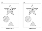
このフレアの影響を低減する方法として、特許文献1では、図14(a)に示すように、パッチ周囲のRGB値が均等化されるようにパッチを並び替えることによって、どのパッチを測定した場合でも、そのパッチの周りからの乱反射の影響が一定になるようにしているが、図14(b)に示すように、人物や風景などの自然画像、パッチ配置を変更出来ないチャート画像などの原稿では、特許文献1のパッチ配置方法は適用することができない。その結果、特許文献1のパッチ配置方法を用いてパッチを並び替えたチャートに基づいて作成したスキャナプロファイルを利用したとしても、上記チャートと原稿とでフレアの影響が異なってしまい、スキャナプロファイルを用いて色変換するための、原稿の各領域のRGB値を適切に推定することができない。 As a method of reducing the influence of this flare, in Patent Document 1, as shown in FIG. 14A, when any patch is measured by rearranging the patches so that the RGB values around the patches are equalized. However, the effect of diffused reflection from around the patch is made constant, but as shown in Fig. 14 (b), manuscripts such as natural images such as people and landscapes, and chart images whose patch arrangement cannot be changed. Then, the patch arrangement method of Patent Document 1 cannot be applied. As a result, even if a scanner profile created based on a chart in which patches are rearranged using the patch arrangement method of Patent Document 1 is used, the influence of flare differs between the chart and the manuscript, and the scanner profile is used. It is not possible to properly estimate the RGB values of each area of the document for color conversion.
そこで、本発明の一実施の形態では、事前に、スキャナプロファイル作成時に、各パッチのRGB値(第1RGB値)を取得すると共に、各パッチを含む周辺パッチのRGB値の平均値(第1RGB平均値)を算出し、第1RGB値と第1RGB平均値とを対応付けて記憶する。次に、原稿の推定対象色の領域をスキャンしてRGB値を取得する際に、各推定対象色の領域の中で取得位置又は取得範囲を変えた複数のRGB値(第2RGB値)を取得し、各々の取得位置又は取得範囲を含む周辺領域のRGB値の平均値(第2RGB平均値)を算出する。そして、算出した複数の第2RGB平均値の中から、推定対象色に対応する第1RGB値に対応付けた第1RGB平均値との差が予め定めた閾値以下となる第2RGB平均値を特定し、特定した第2RGB平均値に対応する位置又は範囲から取得した第2RGB値を、推定対象色のRGB値として選択する。その後、スキャナプロファイルを使用して、選択した第2RGB値をL*a*b*値などに変換する。 Therefore, in one embodiment of the present invention, the RGB values (first RGB values) of each patch are acquired in advance at the time of creating the scanner profile, and the average value of the RGB values of the peripheral patches including each patch (first RGB average). Value) is calculated, and the first RGB value and the first RGB average value are stored in association with each other. Next, when the area of the estimation target color of the original is scanned and the RGB values are acquired, a plurality of RGB values (second RGB values) in which the acquisition position or the acquisition range is changed in each estimation target color area are acquired. Then, the average value (second RGB average value) of the RGB values of the peripheral region including each acquisition position or acquisition range is calculated. Then, from the plurality of calculated second RGB average values, the second RGB average value in which the difference from the first RGB average value associated with the first RGB value corresponding to the estimation target color is equal to or less than a predetermined threshold value is specified. The second RGB value acquired from the position or range corresponding to the specified second RGB average value is selected as the RGB value of the estimation target color. Then, the scanner profile is used to convert the selected second RGB value into an L * a * b * value or the like.
このように、スキャナプロファイルと同様にフレアの影響に受けた推定対象色のRGB値(第2RGB値)を選択することにより、自然画像やパッチ配置を変更できないチャートなどの原稿に対しても適切な色を推定することができ、スキャナプロファイルを用いた色変換の精度を向上させることができる。 In this way, by selecting the RGB value (second RGB value) of the estimated target color affected by flare as in the scanner profile, it is appropriate for manuscripts such as natural images and charts where the patch arrangement cannot be changed. The color can be estimated, and the accuracy of color conversion using the scanner profile can be improved.
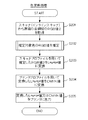
上記した本発明の一実施の形態についてさらに詳細に説明すべく、本発明の一実施例に係る色推定装置、色推定方法及び色推定プログラムについて、図1乃至図12を参照して説明する。図1乃至図3は、本実施例の印刷システムの構成例を示す模式図であり、図4は、本実施例の色推定装置の構成を示すブロック図である。また、図5は、本実施例のプリンタ(スキャナ及び測色器を含む場合)の構成例を示す模式図であり、図6は、プリンタ(色推定装置、スキャナ及び測色器を含む場合)の構成を示すブロック図である。また、図7乃至図9は、本実施例の色推定装置の動作を示すフローチャート図であり、図10乃至図12は、本実施例の色推定方法を説明する模式図である。 In order to explain one embodiment of the present invention in more detail, the color estimation device, the color estimation method, and the color estimation program according to the embodiment of the present invention will be described with reference to FIGS. 1 to 12. 1 to 3 are schematic views showing a configuration example of a printing system of this embodiment, and FIG. 4 is a block diagram showing a configuration of a color estimation device of this embodiment. Further, FIG. 5 is a schematic diagram showing a configuration example of the printer (when including a scanner and a colorimeter) of this embodiment, and FIG. 6 is a schematic diagram showing a printer (when including a color estimator, a scanner and a colorimeter). It is a block diagram which shows the structure of. 7 to 9 are flowcharts showing the operation of the color estimation device of the present embodiment, and FIGS. 10 to 12 are schematic views illustrating the color estimation method of the present embodiment.
なお、以下の説明において、スキャナプロファイルによる変換前の色をRGB値、変換後の色をL*a*b*値とする。 In the following description, the color before conversion by the scanner profile is defined as an RGB value, and the color after conversion is defined as an L * a * b * value.
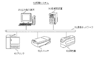
図1に示すように、本実施例の印刷システム10は、出力指示端末20と、色推定装置30と、プリンタ40と、スキャナ50と、測色器60などで構成される。これらはイーサネット(登録商標)、トークンリング、FDDI(Fiber-Distributed Data Interface)等の規格により定められるLAN(Local Area Network)やWAN(Wide Area Network)等の通信ネットワーク70を介して接続されている。なお、色推定装置30とプリンタ40、スキャナ50、測色器60とはPCI(Peripheral Component Interconnect)接続など、専用線で接続されていてもよい。 As shown in FIG. 1, the printing system 10 of this embodiment includes an output instruction terminal 20, a color estimation device 30, a printer 40, a scanner 50, a colorimeter 60, and the like. These are connected via a communication network 70 such as LAN (Local Area Network) or WAN (Wide Area Network) defined by standards such as Ethernet (registered trademark), Token Ring, and FDDI (Fiber-Distributed Data Interface). .. The color estimation device 30, the printer 40, the scanner 50, and the colorimeter 60 may be connected by a dedicated line such as a PCI (Peripheral Component Interconnect) connection.
出力指示端末20は、クライアントのコンピュータ装置であり、プリンタドライバや専用のソフトウェアを用いてジョブを発行する。 The output instruction terminal 20 is a computer device of a client, and issues a job by using a printer driver or dedicated software.
色推定装置30は、プリンタ40から出力されたカラーチャートを用いてスキャナプロファイルや必要に応じてプリンタプロファイルを作成する。また、色推定装置30は、出力指示端末20から発行されたジョブに基づいてプリンタ40から出力された原稿をスキャンして得たRGB値に対して、色変換(RGB値からL*a*b*値への色変換、必要に応じてL*a*b*値からCMYK値への色変換)を行い、色変換後の画像データをプリンタ40に転送する。上記RGB値からL*a*b*値への色変換は予め作成したスキャナプロファイルを用いて行うが、本実施例では、スキャナプロファイルにおけるフレアの影響を考慮して、原稿の各領域の色を推定し、推定した色に対して色変換を行う。この色推定装置30の詳細な構成は後述する。 The color estimation device 30 creates a scanner profile and, if necessary, a printer profile using the color chart output from the printer 40. Further, the color estimation device 30 performs color conversion (from RGB values to L * a * b) with respect to the RGB values obtained by scanning the original output from the printer 40 based on the job issued from the output instruction terminal 20. Color conversion to * value, color conversion from L * a * b * value to CMYK value if necessary) is performed, and the image data after color conversion is transferred to the printer 40. The color conversion from the RGB value to the L * a * b * value is performed using a scanner profile created in advance, but in this embodiment, the color of each area of the document is selected in consideration of the influence of flare on the scanner profile. Estimate and perform color conversion on the estimated color. The detailed configuration of the color estimation device 30 will be described later.
プリンタ40は、色推定装置30から画像データを受け取り、画像データに基づく画像を用紙上に形成して出力する。このプリンタ40の詳細な構成も後述する。 The printer 40 receives image data from the color estimation device 30, forms an image based on the image data on paper, and outputs the image. The detailed configuration of the printer 40 will also be described later.
スキャナ50は、例えば、RGBの3種類のセンサで構成され、プリンタ40から出力されたカラーチャートや原稿をスキャンし、RGB値を出力する。 The scanner 50 is composed of, for example, three types of RGB sensors, scans a color chart or a document output from the printer 40, and outputs RGB values.
測色器60は、光の波長ごとに計測可能なスペクトル方式(分光光度計)の測色器であり、プリンタ40から出力されたカラーチャートを測色し、測色値(L*a*b*値、XYZ値など)を出力する。 The colorimeter 60 is a spectral type (spectral photometric meter) colorimeter that can measure each wavelength of light, measures the color chart output from the printer 40, and measures the color (L * a * b). * Value, XYZ value, etc.) are output.
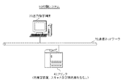
なお、図1は本実施例の印刷システムの一例であり、その構成は適宜変更可能である。例えば、図2に示すように、スキャナ50や測色器60がプリンタ40に内蔵される構成としてもよいし、図3に示すように、更に色推定装置30がプリンタ40に内蔵される構成としてもよい。以下、色推定装置30とプリンタ40について詳細に説明する。 Note that FIG. 1 is an example of the printing system of this embodiment, and its configuration can be changed as appropriate. For example, as shown in FIG. 2, the scanner 50 and the colorimeter 60 may be built in the printer 40, or as shown in FIG. 3, the color estimation device 30 may be further built in the printer 40. May be good. Hereinafter, the color estimation device 30 and the printer 40 will be described in detail.
[色推定装置]
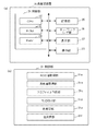
色推定装置30は、図4(a)に示すように、制御部31、記憶部35、ネットワークI/F部36、表示部37、操作部38などで構成される。
[Color estimator]
As shown in FIG. 4A, the color estimation device 30 includes a
制御部31は、CPU(Central Processing Unit)32とROM(Read Only Memory)33やRAM(Random Access Memory)34などのメモリとで構成され、CPU32は、ROM33や記憶部35に記憶した制御プログラムをRAM34に展開して実行することにより、色推定装置30全体の動作を制御する。
The
上記制御部31は、図4(b)に示すように、RGB値取得部31a、測色値取得部31b、プロファイル作成部31c、対応付け部31d、色推定部31e、色変換部31fなどとしても機能する。
As shown in FIG. 4B, the
RGB値取得部31aは、スキャナプロファイル作成時においては、スキャナ50(又は後述するプリンタ40のインラインスキャナ49a)から、カラーチャートの各パッチのRGB値(以下、RGB値1と称す。)を取得する。また、スキャナプロファイル使用時(スキャナプロファイルを用いた色変換時)においては、スキャナ50(又はインラインスキャナ49a)から、原稿の推定対象色の領域内で取得位置又は取得範囲を変えた複数のRGB値(以下、RGB値2と称す。)を取得する。その際、原稿が自然画像かチャート画像かに応じて、複数のRGB値2を取得する方法を切り替えることができる。例えば、原稿が自然画像の場合は、オブジェクト内で取得位置又は取得範囲を変えて複数のRGB値2を取得し、原稿がチャート画像の場合は、原稿の端から順に取得位置をずらして複数のRGB値2を取得することができる。また、RGB値取得部31aは、原稿からRGB値2を取得する際に、スキャナ50(又はプリンタ40のインラインスキャナ49a)の最小読取サイズ(例えば、64ピクセル)以上の領域を確保できる取得位置又は取得範囲を全て探し出し、その中から取得位置又は取得範囲を選択するようにしてもよい。また、カラーチャートと原稿とでフレアの影響を同等にするために、カラーチャートからRGB値1を取得する際の読取サイズでRGB値2を取得できるように、原稿の各推定対象色の領域を分割してもよい。
The RGB
測色値取得部31bは、スキャナプロファイル作成時においては、測色器60(又は後述するプリンタ40のインライン測色器49b)から、カラーチャートの各パッチの測色値(本実施例ではL*a*b*値)を取得する。
At the time of creating the scanner profile, the color measurement value acquisition unit 31b starts with the color measurement value 60 (or the in-line
プロファイル作成部31cは、RGB値取得部31aが取得したカラーチャートの各パッチのRGB値(RGB値1)と測色値取得部31bが取得したカラーチャートの各パッチの測色値(L*a*b*値)とを対応付ける(RGB値を測色値(L*a*b*値)に変換する)スキャナプロファイルを作成する。
The
対応付け部31dは、RGB値取得部31aが取得したカラーチャートの各パッチのRGB値(RGB値1)に基づいて、各パッチを含む周辺パッチ(各パッチを中心とした所定の範囲のパッチ、例えば、3×3のパッチ)のRGB値の平均値(例えば、RGB値の加重平均、以下、RGB平均値1と称す。)を算出し、RGB値1とRGB平均値1とを対応付けて記憶部35などに記憶する。例えば、RGB値1とRGB平均値1とを対応付けるテーブルを作成したり、プロファイル作成部31cが作成したスキャナプロファイルに、各パッチのRGB値1に対応するRGB平均値1を追加したりする。なお、カラーチャートが、パッチ周囲のRGB値が均等化されるようにパッチを並び替えたカラーチャートの場合は、チャート毎にRGB平均値1を記憶すればよく、通常のカラーチャートの場合は、パッチ毎にRGB平均値1を記憶すればよい。
The association unit 31d is a peripheral patch including each patch (a patch in a predetermined range centered on each patch, based on the RGB value (RGB value 1) of each patch of the color chart acquired by the RGB
色推定部31eは、原稿のスキャンデータを解析して、原稿に含まれる同一色の領域を抽出する。また、原稿の各推定対象色について、各々のRGB値2を取得した取得位置又は取得範囲を含む周辺領域(各々の取得位置又は取得範囲を中心とした所定の範囲(好ましくは、上述した周辺パッチと同程度の範囲)の領域)のRGB値の平均値(例えば、RGB値の加重平均、以下、RGB平均値2と称す。)を算出する。そして、算出した複数のRGB平均値2の中から、上記推定対象色に対応するRGB値1に対応付けたRGB平均値1との差が予め定めた閾値以下のRGB平均値2を特定し、特定したRGB平均値2に対応する取得位置又は取得範囲から取得したRGB値2を、推定対象色に対応するRGB値として選択する。その際に、色推定部31eは、RGB平均値1及びRGB平均値2の各RGB値の差が最小となるように、RGB平均値2を特定することができる。
The
色変換部31fは、スキャナプロファイルを用いて、原稿の各推定対象色に対して色推定部31eが選択したRGB値2をL*a*b*値に変換する。また、色変換部31fは、必要に応じて、プリンタプロファイルを用いて、変換したL*a*b*値をCMYK値に変換する。そして、色変換部31fは、L*a*b*値又はCMYK値をプリンタ40(印刷処理部49)に出力する。
The color conversion unit 31f uses the scanner profile to convert the RGB value 2 selected by the
上記RGB値取得部31a、測色値取得部31b、プロファイル作成部31c、対応付け部31d、色推定部31e、色変換部31fは、ハードウェアとして構成してもよいし、制御部31を、RGB値取得部31a、測色値取得部31b、プロファイル作成部31c、対応付け部31d、色推定部31e、色変換部31f(特に、RGB値取得部31a、測色値取得部31b、対応付け部31d、色推定部31e)として機能させる色推定プログラムとして構成し、当該色推定プログラムをCPU32に実行させる構成としてもよい。
The RGB
記憶部35は、HDD(Hard Disk Drive)やSSD(Solid State Drive)などで構成され、CPU32が各部を制御するためのプログラム、自装置の処理機能に関する情報、測色値取得部31bが取得したRGB値、測色値取得部31bが取得した測色値、プロファイル作成部31cが作成したスキャナプロファイル、対応付け部31dが作成したテーブルなどを記憶する。
The
ネットワークI/F部36は、NIC(Network Interface Card)やモデムなどで構成され、色推定装置30を通信ネットワーク70に接続し、出力指示端末20やプリンタ40、スキャナ50、測色器60とのデータ通信を可能にする。
The network I /
表示部37は、LCD(Liquid Crystal Display)や有機EL(Electro Luminescence)ディスプレイなどであり、スキャナプロファイルの作成や原稿の色変換などに関する各種画面を表示する。
The
操作部38は、マウス、キーボード、ハードスイッチなどであり、スキャナプロファイルの作成や原稿の色変換などに関する各種操作を可能にする。
The
[プリンタ]
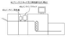
プリンタ40は、MFP(Multi-Functional Peripherals)などの画像形成装置であり、スキャナプロファイル作成用のカラーチャートや、スキャナプロファイルを用いて色変換を行う原稿(例えば、人物や風景などの自然画像やパッチ配置を変更出来ないチャート画像)などを出力する。このプリンタ40は、図6(a)に示すように、制御部41、記憶部45、ネットワークI/F部46、表示操作部47、画像処理部48、印刷処理部49などで構成される。
[Printer]
The printer 40 is an image forming apparatus such as an MFP (Multi-Functional Peripherals), and is a color chart for creating a scanner profile or a document (for example, a natural image or patch of a person or landscape) that undergoes color conversion using the scanner profile. (Chart image) whose arrangement cannot be changed) is output. As shown in FIG. 6A, the printer 40 includes a control unit 41, a
制御部41は、CPU42とROM43やRAM44などのメモリとで構成され、CPU42は、ROM43や記憶部45に記憶した制御プログラムをRAM44に展開して実行することにより、プリンタ40全体の動作を制御する。プリンタ40が色推定装置30の機能を備える場合、上記制御部41は、図6(b)に示すように、プロファイル作成部41a、対応付け部41b、色推定部41cなどとしても機能する。なお、プロファイル作成部41a、対応付け部41b、色推定部41cの機能は、色推定装置30のプロファイル作成部31c、対応付け部31d、色推定部31eと同様であるため、説明を省略する。
The control unit 41 is composed of a
記憶部45は、HDDやSSDなどで構成され、CPU42が各部を制御するためのプログラム、自装置の処理機能に関する情報、プリンタプロファイル、必要に応じて、後述するインラインスキャナ49aが取得したRGB値、インライン測色器49bが取得した測色値、プロファイル作成部41aが作成したスキャナプロファイル、対応付け部41bが作成したテーブルなどを記憶する。
The
ネットワークI/F部46は、NICやモデムなどで構成され、プリンタ40を通信ネットワーク70に接続し、色推定装置30などとのデータ通信を可能にする。
The network I /
表示操作部47は、表示部上に透明電極が格子状に配置された感圧式の操作部(タッチセンサ)を設けたタッチパネルなどであり、印刷処理に関する各種画面を表示し、印刷処理に関する各種操作を可能にする。また、プリンタ40が色推定装置30の機能を備える場合は、表示操作部47は、スキャナプロファイルの作成や原稿の色変換などに関する各種画面を表示し、スキャナプロファイルの作成や原稿の色変換などに関する各種操作を可能にする。
The
画像処理部48は、予め作成したプリンタプロファイルを用いて、原稿のL*a*b*値をCMYK値に色変換する。そして、色変換後の画像に対して、画像処理(色調整、濃度調整、サイズ調整などの処理)やスクリーニングを行い、画像処理後の画像データを印刷処理部49に転送する。なお、プリンタ40が色推定装置30の機能を備える場合は、画像処理部48は、プロファイル作成部41aが作成したスキャナプロファイルを用いて、原稿のRGB値をL*a*b*値に色変換する。
The
印刷処理部(印刷エンジン)49は、画像処理後の画像データに基づいて印刷処理を実行する。この印刷処理部49は、帯電装置により帯電された感光体ドラムに露光装置から画像に応じた光を照射して静電潜像を形成し、現像装置で帯電したトナーを付着させて現像し、そのトナー像を転写ベルトに1次転写し、転写ベルトから用紙に2次転写し、更に定着装置で用紙上のトナー像を定着させる処理を行う。また、図5に示すように、プリンタ40がスキャナ50及び測色器60の機能を備える場合、印刷処理部49は、インラインスキャナ49a及びインライン測色器49bを含む。
The print processing unit (print engine) 49 executes the print process based on the image data after the image process. The
インラインスキャナ49aは、例えば、RGBの3種類のセンサで構成され、RGBセンサで取得したRGB値を出力する。このインラインスキャナ49aは、プリンタ40が色推定装置30の機能を備える場合は、RGB値取得部として機能する。
The in-
インライン測色器49bは、例えば、外部測色器と同様に光の波長ごとに計測可能なスペクトル方式(分光光度計)の測色器であり、外部測色器と同様な精度で測色値(L*a*b*値、XYZ値など)を出力する。このインライン測色器49bは、プリンタ40が色推定装置30の機能を備える場合は、測色値取得部として機能する。
The in-
なお、図4乃至図6は、本実施例の色推定装置30及びプリンタ40の一例であり、その構成は適宜変更可能である。 4 to 6 are examples of the color estimation device 30 and the printer 40 of this embodiment, and their configurations can be changed as appropriate.
例えば、色推定装置30がスキャナプロファイルを作成する場合は、色推定装置30は、プリンタ40、スキャナ50及び測色器60(又はインラインスキャナ及びインライン測色器を備えるプリンタ40)を制御するコントローラとして機能させることができ、色推定装置30が予め作成されたスキャナプロファイルを利用する(すなわち、スキャナプロファイルの作成は行わない)場合は、色推定装置30は、スキャナ50(又はインラインスキャナを備えるプリンタ40)を制御するコントローラとして機能させることができる。 For example, when the color estimation device 30 creates a scanner profile, the color estimation device 30 serves as a controller for controlling a printer 40, a scanner 50, and a colorimeter 60 (or a printer 40 including an in-line scanner and an in-line colorimeter). If the color estimation device 30 can function and the color estimation device 30 utilizes a pre-created scanner profile (that is, does not create a scanner profile), the color estimation device 30 is a printer 50 (or a printer 40 including an in-line scanner). ) Can function as a controller to control.
以下、本実施例の色推定装置30(又は、色推定装置30の機能を備えるプリンタ40)の動作について説明する。CPU32は、ROM33又は記憶部35に記憶した色推定プログラムをRAM34に展開して実行することにより、図7乃至図9のフローチャート図に示す各ステップの処理を実行する。
Hereinafter, the operation of the color estimation device 30 (or the printer 40 having the function of the color estimation device 30) of this embodiment will be described. The
[スキャナプロファイル作成処理]
まず、スキャナプロファイルを作成する手順について、図7のフローチャート図を参照して説明する。なお、本実施例では、色推定装置30がスキャナプロファイルを作成し、作成したスキャナプロファイルを用いて後述する色変換を行うが、予め作成されたスキャナプロファイルを取得し、取得したスキャナプロファイルを用いて後述する色変換を行ってもよい。
[Scanner profile creation process]
First, the procedure for creating the scanner profile will be described with reference to the flowchart of FIG. 7. In this embodiment, the color estimation device 30 creates a scanner profile and performs color conversion described later using the created scanner profile. However, a scanner profile created in advance is acquired, and the acquired scanner profile is used. Color conversion described later may be performed.
図7に示すように、色推定装置30の制御部31は、プリンタの色域全体の情報が取得できるようにパッチを配置したカラーチャートの画像データを生成してプリンタ40に送信し、プリンタ40にカラーチャートを出力させる(S101)。その際、特許文献1の技術を利用して、パッチ周囲のRGB値が均等化されるようにパッチを並び替えたカラーチャートを出力させてもよい。
As shown in FIG. 7, the
次に、制御部31(RGB取得部31a)は、スキャナ50(若しくはプリンタ40のインラインスキャナ49a)から上記カラーチャートの各パッチのRGB値(RGB値1)を取得する(S102)。
Next, the control unit 31 (
次に、制御部31(測色値取得部31b)は、測色器60(若しくはプリンタ40のインライン測色器49b)から上記カラーチャートの各パッチの測色値(L*a*b*値)を取得する(S103)。
Next, the control unit 31 (color measurement value acquisition unit 31b) starts with the color measurement device 60 (or the in-line
次に、制御部31(プロファイル作成部31c)は、チャートの各パッチのRGB値1と測色値(L*a*b*値)とを対応付ける色変換テーブル(スキャナプロファイル)を作成し、記憶部35などに記憶する(S104)。
Next, the control unit 31 (
次に、制御部31(対応付け部31d)は、カラーチャートの各パッチを含む周辺パッチのRGB平均値1を算出し(S105)、RGB値1とRGB平均値1とを対応付けて記憶する(S106)。例えば、RGB値1とRGB平均値1とを対応付けるテーブルを作成したり、スキャナプロファイルのRGB値1にRGB平均値1を対応付けてスキャナプロファイルを修正したりする。なお、カラーチャートが、パッチ周囲のRGB値が均等化されるようにパッチを並び替えたカラーチャートの場合は、チャート毎にRGB平均値1を記憶すればよく、通常のカラーチャートの場合は、パッチ毎にRGB平均値1を記憶すればよい。 Next, the control unit 31 (correspondence unit 31d) calculates the RGB average value 1 of the peripheral patches including each patch of the color chart (S105), and stores the RGB value 1 and the RGB average value 1 in association with each other. (S106). For example, a table for associating the RGB value 1 with the RGB average value 1 is created, or the scanner profile is modified by associating the RGB value 1 of the scanner profile with the RGB average value 1. If the color chart is a color chart in which the patches are rearranged so that the RGB values around the patches are equalized, the RGB average value 1 may be stored for each chart, and in the case of a normal color chart, the RGB values may be stored. The RGB average value 1 may be stored for each patch.
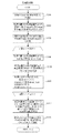
[色変換処理]
次に、原稿のRGB値を測色値(L*a*b*値)に変換する手順について、図8及び図9のフローチャート図を参照して説明する。
[Color conversion process]
Next, the procedure for converting the RGB value of the document into the color measurement value (L * a * b * value) will be described with reference to the flowcharts of FIGS. 8 and 9.
図8に示すように、制御部31(RGB取得部31a)は、スキャナ50(若しくはプリンタ40のインラインスキャナ49a)から、原稿の各領域のRGB値(RGB値2)を取得する(S201)。
As shown in FIG. 8, the control unit 31 (
次に、制御部31(色推定部31e)は、原稿の推定対象色のRGB値を推定する(S202)。
Next, the control unit 31 (
図9はこのステップの詳細を示しており、制御部31(色推定部31e)は、推定対象色として任意のCMYK値を選択する(S301)。
FIG. 9 shows the details of this step, and the control unit 31 (
次に、制御部31(色推定部31e)は、取得位置又は取得範囲を変えた複数(n個)のRGB値2及びRGB平均値2を取得する方法を決定する(S302)。具体的には、原稿が自然画像かチャート画像かに応じて、複数のRGB値2及びRGB平均値2を取得する方法を選択する。例えば、原稿が自然画像の場合は、オブジェクト内で取得位置又は取得範囲を変えて複数のRGB値2を取得し、原稿がチャート画像の場合は、原稿の端から順に取得位置をずらして複数のRGB値2を取得する。
Next, the control unit 31 (
次に、制御部31(色推定部31e)は、n個の取得位置又は取得範囲毎のRGB値2と、取得位置又は取得範囲を含む周辺領域(取得位置又は取得範囲を中心とした所定の範囲の領域)のRGB平均値2と、を格納する箱(記憶領域、RGB_BOX[n][2])を用意する(S303)。
Next, the control unit 31 (
次に、制御部31(色推定部31e)は、以下のS304〜306のステップをn回ループして実行する。具体的には、原稿のスキャンデータを解析して推定対象色の領域を抽出し、その領域に対して取得位置又は取得範囲を変えてRGB値2(Block_RGB)を取得し(S304)、その取得位置又は取得範囲を含む周辺領域のRGB平均値2(PeripheryAve_RGB)を取得する(S305)。そして、取得したデータをそれぞれRGB_BOXへ代入する(S306)。すなわち、RGB_BOX[n][0]にBlock_RGBを代入し、RGB_BOX[n][1]にPeripheryAve_RGBを代入する。
Next, the control unit 31 (
次に、制御部31(色推定部31e)は、記憶部35などに記憶したテーブルや修正したスキャナプロファイルを参照して、推定対象色に対応するRGB値1に対応付けたRGB平均値1を読み出し、このRGB平均値1と上記n個のRGB平均値2とを比較し、RGB平均値1との差が予め定めた閾値以下のRGB平均値2を特定する(S307)。
Next, the control unit 31 (
そして、制御部31(色推定部31e)は、上記S307で特定したRGB平均値2に対応する取得位置又は取得範囲から取得したRGB値2を、S301で選択した推定対象色に対応するRGB値として選択する(S308)。
Then, the control unit 31 (
図8に戻って、制御部31(色変換部31f)は、図7のS104で作成したスキャナプロファイルを用いて、S202で推定したRGB値(選択したRGB値2)をL*a*b*値に変換する(S203)。 Returning to FIG. 8, the control unit 31 (color conversion unit 31f) uses the scanner profile created in S104 of FIG. 7 to obtain the RGB value (selected RGB value 2) estimated in S202 by L * a * b *. Convert to a value (S203).
次に、制御部31(色変換部31f)は、必要に応じて、プリンタプロファイルを用いて、S203で変換したL*a*b*値をCMYK値に変換する(S204)。 Next, the control unit 31 (color conversion unit 31f) converts the L * a * b * value converted in S203 into a CMYK value using the printer profile, if necessary (S204).
次に、制御部31(色変換部31f)は、S203で変換したL*a*b*値、又は、S204で変換したCMYK値をプリンタ40に出力して印刷を指示する(S205)。 Next, the control unit 31 (color conversion unit 31f) outputs the L * a * b * value converted in S203 or the CMYK value converted in S204 to the printer 40 to instruct printing (S205).
以下、本実施例の色推定方法について具体例を挙げて説明する。 Hereinafter, the color estimation method of this embodiment will be described with reference to specific examples.
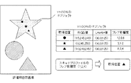
図10は、本実施例の色推定方法を説明する模式図である。図の左側のように、星形、円形、三角形の3つのオブジェクト(オブジェクトの色の違いをハッチングの種類を変えて表現している。)を含む評価用自然画像において、星形のオブジェクトがY100%のオブジェクトの場合、図の右側の表の「L*a*b*値」の欄に示すように、そのオブジェクト内の3つの取得位置(黒塗りの丸、星、三角)におけるL*a*b*値は同じ値であっても、「RGB値」の欄に示すように、スキャナで測定するRGB値はフレアの影響により変化する。ここで、ある位置のRGB値とその位置の周辺のRGB平均値との差分をフレア影響度と定義する。スキャナプロファイルのY100%のオブジェクトのフレア影響度が(7,2,4)の場合、その値と「フレア影響度」の欄に示す各々の取得位置のフレア影響度とを比較し、スキャナプロファイルのフレア影響度に最も近い三角を取得位置に決定し、決定した取得位置におけるRGB値(10,240,245)をY100%のオブジェクトのRGB値として選択する。 FIG. 10 is a schematic diagram illustrating the color estimation method of this embodiment. As shown on the left side of the figure, in the evaluation natural image including three objects of star shape, circle, and triangle (the difference in the color of the object is expressed by changing the type of hatching), the star shape object is Y100. In the case of% object, as shown in the "L * a * b * value" column of the table on the right side of the figure, L * a at the three acquisition positions (black circle, star, triangle) in the object. Even if the * b * values are the same, as shown in the "RGB value" column, the RGB value measured by the scanner changes due to the influence of flare. Here, the difference between the RGB value at a certain position and the RGB average value around that position is defined as the flare influence degree. If the flare impact of an object with Y100% of the scanner profile is (7,2,4), compare that value with the flare impact of each acquisition position shown in the "flare impact" column, and compare the flare impact of the scanner profile. The triangle closest to the flare influence degree is determined as the acquisition position, and the RGB value (10,240,245) at the determined acquisition position is selected as the RGB value of the Y100% object.
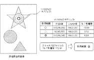
図11は、本実施例の色推定方法の他の例を説明する模式図である。図10と同様に、図の左側のように、星形、円形、三角形の3つのオブジェクトを含む評価用自然画像において、星形のオブジェクトがY100%のオブジェクトの場合、図の右側の表の「L*a*b*値」の欄に示すように、そのオブジェクト内の3つの取得範囲(細い実線、細い破線、太い実線)におけるL*a*b*値は同じ値であっても、「RGB値」の欄に示すように、スキャナで測定するRGB値はフレアの影響により変化する。ここで、スキャナプロファイルのフレア影響度が(7,2,4)の場合、その値と「フレア影響度」の欄に示す各々の取得範囲のフレア影響度とを比較し、スキャナプロファイルのフレア影響度に最も近い太い実線を取得範囲に決定し、決定した取得範囲におけるRGB値(10,240,245)をY100%のオブジェクトのRGB値として選択する。 FIG. 11 is a schematic diagram illustrating another example of the color estimation method of this embodiment. Similar to FIG. 10, in the evaluation natural image including three objects of star shape, circle, and triangle as shown on the left side of the figure, when the star shape object is an object of Y100%, the table on the right side of the figure shows " As shown in the "L * a * b * value" column, even if the L * a * b * values in the three acquisition ranges (thin solid line, thin broken line, and thick solid line) in the object are the same value, "L * a * b * value" As shown in the "RGB value" column, the RGB value measured by the scanner changes due to the influence of flare. Here, when the flare influence degree of the scanner profile is (7,2,4), the value is compared with the flare influence degree of each acquisition range shown in the "flare influence degree" column, and the flare influence degree of the scanner profile is compared. The thick solid line closest to the degree is determined as the acquisition range, and the RGB values (10,240,245) in the determined acquisition range are selected as the RGB values of the Y100% object.
なお、図10及び図11では、オブジェクトが均一の色(Y100%)の場合について記載したが、オブジェクト内で色が変化する場合もある。例えば、図12に示すように、星形のオブジェクトの色がオブジェクト内部で変化している(オブジェクトの色の変化をハッチングの種類を変えて表現している。)場合は、取得位置又は取得範囲を設定する際に、対象のオブジェクトの中の同じ色の領域(RGB値が近い領域)の中から複数の取得位置又は取得範囲を設定することが好ましい。 Although FIGS. 10 and 11 have described the case where the object has a uniform color (Y100%), the color may change within the object. For example, as shown in FIG. 12, when the color of the star-shaped object changes inside the object (the change in the color of the object is expressed by changing the type of hatching), the acquisition position or the acquisition range. It is preferable to set a plurality of acquisition positions or acquisition ranges from the same color area (areas having similar RGB values) in the target object.
このように、スキャナプロファイルにおけるフレアの影響を考慮して、推定対象色のRGB値の取得位置又は取得範囲を決定し、その取得位置又は取得範囲のRGB値を選択することにより、自然画像やパッチ配置を変更できないチャートなどの原稿に対しても、適切に色を推定することができ、スキャナプロファイルを用いた色変換の精度を向上させることができる。 In this way, the acquisition position or acquisition range of the RGB value of the estimation target color is determined in consideration of the influence of flare on the scanner profile, and the RGB value of the acquisition position or acquisition range is selected to obtain a natural image or patch. Colors can be estimated appropriately even for documents such as charts whose arrangement cannot be changed, and the accuracy of color conversion using the scanner profile can be improved.
なお、本発明は上記実施例に限定されるものではなく、本発明の趣旨を逸脱しない限りにおいて、システムや各装置の構成や制御は適宜変更可能である。 The present invention is not limited to the above embodiment, and the configuration and control of the system and each device can be appropriately changed as long as the gist of the present invention is not deviated.
例えば、上記実施例では、測色値としてCIE 1976色空間のL*a*b*値を例示したが、CIE 1931色空間のXYZ値としてもよいし、CIECAM02などの色の見えモデルなどとしてもよく、特に制限されない。 For example, in the above embodiment, the L * a * b * value in the CIE 1976 color space is illustrated as the color measurement value, but it may be the XYZ value in the CIE 1931 color space, or it may be used as a color appearance model such as CIECAM02. Well, there are no particular restrictions.
また、上記実施例では、色推定装置30がスキャナプロファイルの作成及びスキャナプロファイルを用いた色変換を行う場合について記載したが、プリンタ40がスキャナプロファイルの作成及びスキャナプロファイルを用いた色変換を行う場合においても、本発明の色推定方法を同様に適用することができる。 Further, in the above embodiment, the case where the color estimation device 30 creates the scanner profile and performs the color conversion using the scanner profile has been described, but the case where the printer 40 creates the scanner profile and performs the color conversion using the scanner profile. In the same manner, the color estimation method of the present invention can be applied.
本発明は、スキャナプロファイルにおけるフレアの影響を考慮して原稿の色を推定する色推定装置、当該色推定装置を含むシステムにおける色推定方法、当該色推定装置を含むシステムで動作する色推定プログラム及び当該色推定プログラムを記録した記録媒体に利用可能である。 The present invention relates to a color estimation device that estimates the color of a document in consideration of the influence of flare on a scanner profile, a color estimation method in a system including the color estimation device, a color estimation program operating in the system including the color estimation device, and a color estimation device. It can be used as a recording medium on which the color estimation program is recorded.
10 印刷システム
20 出力指示端末
30 色推定装置
31 制御部
31a RGB値取得部
31b 測色値取得部
31c プロファイル作成部
31d 対応付け部
31e 色推定部
31f 色変換部
32 CPU
33 ROM
34 RAM
35 記憶部
36 ネットワークI/F部
37 表示部
38 操作部
40 プリンタ
41 制御部
41a プロファイル作成部
41b 対応付け部
41c 色推定部
42 CPU
43 ROM
44 RAM
45 記憶部
46 ネットワークI/F部
47 表示操作部
48 画像処理部
49 印刷処理部
49a インラインスキャナ
49b インライン測色器
50 スキャナ
60 測色器
70 通信ネットワーク
10 Printing system 20 Output instruction terminal 30
33 ROM
34 RAM
35
43 ROM
44 RAM
45
Claims (24)
前記チャートの各パッチの測色値を取得する測色値取得部と、
前記チャートの各パッチについて、当該パッチを含む周辺パッチのRGB値の平均である第1RGB平均値を算出し、前記各パッチの前記第1RGB値と前記第1RGB平均値とを対応付けて記憶する対応付け部と、
原稿の各対象色のRGB値を推定する色推定部と、を備え、
前記RGB値取得部は、前記原稿の各対象色の領域内で位置又は範囲を変えた複数の第2RGB値を取得し、
前記色推定部は、前記各対象色について、各々の前記第2RGB値を取得した位置又は範囲を含む周辺領域のRGB値の平均である第2RGB平均値を算出し、算出した複数の前記第2RGB平均値の中から、当該対象色に対応する前記第1RGB値に対応付けた前記第1RGB平均値との差が予め定めた閾値以下の前記第2RGB平均値を特定し、特定した前記第2RGB平均値に対応する位置又は範囲から取得した前記第2RGB値を、前記対象色のRGB値として選択する、
ことを特徴とする色推定装置。 The RGB value acquisition unit that acquires the first RGB value of each patch of the chart,
A color measurement value acquisition unit that acquires the color measurement value of each patch in the chart,
For each patch in the chart, the first RGB average value, which is the average of the RGB values of the peripheral patches including the patch, is calculated, and the first RGB value of each patch and the first RGB average value are stored in association with each other. With the patch
It is equipped with a color estimation unit that estimates the RGB values of each target color of the document.
The RGB value acquisition unit acquires a plurality of second RGB values whose positions or ranges are changed within the region of each target color of the document.
For each of the target colors, the color estimation unit calculates a second RGB average value which is an average of the RGB values of the peripheral region including the position or range where the second RGB value is acquired, and the calculated second RGB values. From the average values, the second RGB average value whose difference from the first RGB average value associated with the first RGB value corresponding to the target color is equal to or less than a predetermined threshold is specified, and the specified second RGB average is specified. The second RGB value acquired from the position or range corresponding to the value is selected as the RGB value of the target color.
A color estimation device characterized by the fact that.
前記スキャナプロファイルを用いて、前記原稿の各対象色のRGB値として選択された前記第2RGB値を前記測色値に変換する色変換部と、を更に備える、
ことを特徴とする請求項1に記載の色推定装置。 A profile creation unit that creates a scanner profile that associates the first RGB value with the color measurement value,
A color conversion unit that converts the second RGB value selected as the RGB value of each target color of the document into the color measurement value by using the scanner profile is further provided.
The color estimation device according to claim 1.
ことを特徴とする請求項1又は2に記載の色推定装置。 The color estimation unit specifies the second RGB average value so that the difference between the first RGB average value and the second RGB average value is minimized.
The color estimation device according to claim 1 or 2.
前記対応付け部は、チャート毎に前記第1RGB平均値を記憶する、
ことを特徴とする請求項1乃至3のいずれか一に記載の色推定装置。 The chart is a chart in which patches are rearranged so that the first RGB average value becomes a constant value in the chart.
The association unit stores the first RGB average value for each chart.
The color estimation device according to any one of claims 1 to 3, wherein the color estimation device is characterized.
ことを特徴とする請求項1乃至3のいずれか一に記載の色推定装置。 The association unit stores the first RGB average value for each patch.
The color estimation device according to any one of claims 1 to 3, wherein the color estimation device is characterized.
ことを特徴とする請求項1乃至5のいずれか一に記載の色推定装置。 The RGB value acquisition unit switches a method of acquiring a plurality of the second RGB values depending on whether the original is a natural image or a chart image.
The color estimation device according to any one of claims 1 to 5, wherein the color estimation device is characterized.
ことを特徴とする請求項1乃至6のいずれか一に記載の色推定装置。 When acquiring the second RGB value from the original, the RGB value acquisition unit searches for all positions or ranges in which an area equal to or larger than the minimum reading size can be secured.
The color estimation device according to any one of claims 1 to 6, wherein the color estimation device is characterized.
ことを特徴とする請求項1乃至7のいずれか一に記載の色推定装置。 The RGB value acquisition unit divides a region of each target color of the document so that the second RGB value can be acquired by the reading size when the first RGB value is acquired from the chart.
The color estimation device according to any one of claims 1 to 7, wherein the color estimation device is characterized.
チャートの各パッチの第1RGB値を取得する第1取得処理と、
前記チャートの各パッチの測色値を取得する第2取得処理と、
前記チャートの各パッチについて、当該パッチを含む周辺パッチのRGB値の平均である第1RGB平均値を算出し、前記各パッチの前記第1RGB値と前記第1RGB平均値とを対応付けて記憶する対応付け処理と、
前記原稿の各対象色の領域内で位置又は範囲を変えた複数の第2RGB値を取得する第3取得処理と、
前記各対象色について、各々の前記第2RGB値を取得した位置又は範囲を含む周辺領域のRGB値の平均である第2RGB平均値を算出し、算出した複数の前記第2RGB平均値の中から、当該対象色に対応する前記第1RGB値に対応付けた前記第1RGB平均値との差が予め定めた閾値以下の前記第2RGB平均値を特定し、特定した前記第2RGB平均値に対応する位置又は範囲から取得した前記第2RGB値を、前記対象色のRGB値として選択する色推定処理と、を実行する、
ことを特徴とする色推定方法。 A color estimation method in a system that estimates the RGB values of each target color of a document.
The first acquisition process to acquire the first RGB value of each patch of the chart, and
The second acquisition process for acquiring the color measurement value of each patch in the chart, and
For each patch in the chart, the first RGB average value, which is the average of the RGB values of the peripheral patches including the patch, is calculated, and the first RGB value of each patch and the first RGB average value are stored in association with each other. With the patching process
A third acquisition process for acquiring a plurality of second RGB values whose positions or ranges are changed within the area of each target color of the document, and
For each of the target colors, the second RGB average value, which is the average of the RGB values of the peripheral region including the position or range where the second RGB value was acquired, was calculated, and the calculated second RGB average value was selected from among the plurality of calculated second RGB average values. The second RGB average value whose difference from the first RGB average value associated with the first RGB value corresponding to the target color is equal to or less than a predetermined threshold is specified, and the position corresponding to the specified second RGB average value or A color estimation process of selecting the second RGB value acquired from the range as the RGB value of the target color is executed.
A color estimation method characterized by that.
前記スキャナプロファイルを用いて、前記原稿の各対象色のRGB値として選択された前記第2RGB値を前記測色値に変換する色変換処理と、を更に実行する、
ことを特徴とする請求項9に記載の色推定方法。 A profile creation process for creating a scanner profile that associates the first RGB value with the color measurement value,
Using the scanner profile, a color conversion process for converting the second RGB value selected as the RGB value of each target color of the document into the color measurement value is further executed.
The color estimation method according to claim 9.
ことを特徴とする請求項9又は10に記載の色推定方法。 In the color estimation process, the second RGB average value is specified so that the difference between the first RGB average value and the second RGB average value is minimized.
The color estimation method according to claim 9 or 10.
前記対応付け処理では、チャート毎に前記第1RGB平均値を記憶する、
ことを特徴とする請求項9乃至11のいずれか一に記載の色推定方法。 The chart is a chart in which patches are rearranged so that the first RGB average value becomes a constant value in the chart.
In the association process, the first RGB average value is stored for each chart.
The color estimation method according to any one of claims 9 to 11, wherein the color estimation method is characterized.
ことを特徴とする請求項9乃至11のいずれか一に記載の色推定方法。 In the association process, the first RGB average value is stored for each patch.
The color estimation method according to any one of claims 9 to 11, wherein the color estimation method is characterized.
ことを特徴とする請求項9乃至13のいずれか一に記載の色推定方法。 In the third acquisition process, the method of acquiring a plurality of the second RGB values is switched depending on whether the original is a natural image or a chart image.
The color estimation method according to any one of claims 9 to 13, wherein the color estimation method is characterized.
ことを特徴とする請求項9乃至14のいずれか一に記載の色推定方法。 In the third acquisition process, when acquiring the second RGB value from the document, all positions or ranges that can secure an area equal to or larger than the minimum reading size are searched for.
The color estimation method according to any one of claims 9 to 14, characterized in that.
ことを特徴とする請求項9乃至15のいずれか一に記載の色推定方法。 In the third acquisition process, the region of each target color of the document is divided so that the second RGB value can be acquired by the reading size when the first RGB value is acquired from the chart.
The color estimation method according to any one of claims 9 to 15, characterized in that.
前記装置に、
チャートの各パッチの第1RGB値を取得する第1取得処理、
前記チャートの各パッチの測色値を取得する第2取得処理、
前記チャートの各パッチについて、当該パッチを含む周辺パッチのRGB値の平均である第1RGB平均値を算出し、前記各パッチの前記第1RGB値と前記第1RGB平均値とを対応付けて記憶する対応付け処理、
前記原稿の各対象色の領域内で位置又は範囲を変えた複数の第2RGB値を取得する第3取得処理、
前記各対象色について、各々の前記第2RGB値を取得した位置又は範囲を含む周辺領域のRGB値の平均である第2RGB平均値を算出し、算出した複数の前記第2RGB平均値の中から、当該対象色に対応する前記第1RGB値に対応付けた前記第1RGB平均値との差が予め定めた閾値以下の前記第2RGB平均値を特定し、特定した前記第2RGB平均値に対応する位置又は範囲から取得した前記第2RGB値を、前記対象色のRGB値として選択する色推定処理、を実行させる、
ことを特徴とする色推定プログラム。 A color estimation program operated by a device in the system that estimates the RGB values of each target color of the document.
In the device
First acquisition process to acquire the first RGB value of each patch in the chart,
The second acquisition process of acquiring the color measurement value of each patch in the chart,
For each patch in the chart, the first RGB average value, which is the average of the RGB values of the peripheral patches including the patch, is calculated, and the first RGB value of each patch and the first RGB average value are stored in association with each other. Patching process,
A third acquisition process for acquiring a plurality of second RGB values whose positions or ranges are changed within the area of each target color of the document.
For each of the target colors, the second RGB average value, which is the average of the RGB values of the peripheral region including the position or range where the second RGB value was acquired, was calculated, and the calculated second RGB average value was selected from among the plurality of calculated second RGB average values. The second RGB average value whose difference from the first RGB average value associated with the first RGB value corresponding to the target color is equal to or less than a predetermined threshold is specified, and the position corresponding to the specified second RGB average value or A color estimation process of selecting the second RGB value acquired from the range as the RGB value of the target color is executed.
A color estimation program characterized by that.
前記第1RGB値と前記測色値とを対応付けるスキャナプロファイルを作成するプロファイル作成処理、
前記スキャナプロファイルを用いて、前記原稿の各対象色のRGB値として選択された前記第2RGB値を前記測色値に変換する色変換処理、を実行させる、
ことを特徴とする請求項17に記載の色推定プログラム。 In addition to the device
A profile creation process for creating a scanner profile that associates the first RGB value with the color measurement value.
Using the scanner profile, a color conversion process for converting the second RGB value selected as the RGB value of each target color of the document into the color measurement value is executed.
The color estimation program according to claim 17.
ことを特徴とする請求項17又は18に記載の色推定プログラム。 In the color estimation process, the second RGB average value is specified so that the difference between the first RGB average value and the second RGB average value is minimized.
The color estimation program according to claim 17 or 18.
前記対応付け処理では、チャート毎に前記第1RGB平均値を記憶する、
ことを特徴とする請求項17乃至19のいずれか一に記載の色推定プログラム。 The chart is a chart in which patches are rearranged so that the first RGB average value becomes a constant value in the chart.
In the association process, the first RGB average value is stored for each chart.
The color estimation program according to any one of claims 17 to 19, wherein the color estimation program is characterized.
ことを特徴とする請求項17乃至19のいずれか一に記載の色推定プログラム。 In the association process, the first RGB average value is stored for each patch.
The color estimation program according to any one of claims 17 to 19, wherein the color estimation program is characterized.
ことを特徴とする請求項17乃至21のいずれか一に記載の色推定プログラム。 In the third acquisition process, the method of acquiring a plurality of the second RGB values is switched depending on whether the original is a natural image or a chart image.
The color estimation program according to any one of claims 17 to 21, characterized in that.
ことを特徴とする請求項17乃至22のいずれか一に記載の色推定プログラム。 In the third acquisition process, when acquiring the second RGB value from the document, all positions or ranges that can secure an area equal to or larger than the minimum reading size are searched for.
The color estimation program according to any one of claims 17 to 22, wherein the color estimation program is characterized.
ことを特徴とする請求項17乃至23のいずれか一に記載の色推定プログラム。 In the third acquisition process, the region of each target color of the document is divided so that the second RGB value can be acquired by the reading size when the first RGB value is acquired from the chart.
The color estimation program according to any one of claims 17 to 23.
Priority Applications (1)
| Application Number | Priority Date | Filing Date | Title |
|---|---|---|---|
| JP2017239351A JP6954079B2 (en) | 2017-12-14 | 2017-12-14 | Color estimator, color estimation method and color estimation program |
Applications Claiming Priority (1)
| Application Number | Priority Date | Filing Date | Title |
|---|---|---|---|
| JP2017239351A JP6954079B2 (en) | 2017-12-14 | 2017-12-14 | Color estimator, color estimation method and color estimation program |
Publications (2)
| Publication Number | Publication Date |
|---|---|
| JP2019106658A JP2019106658A (en) | 2019-06-27 |
| JP6954079B2 true JP6954079B2 (en) | 2021-10-27 |
Family
ID=67062099
Family Applications (1)
| Application Number | Title | Priority Date | Filing Date |
|---|---|---|---|
| JP2017239351A Active JP6954079B2 (en) | 2017-12-14 | 2017-12-14 | Color estimator, color estimation method and color estimation program |
Country Status (1)
| Country | Link |
|---|---|
| JP (1) | JP6954079B2 (en) |
Families Citing this family (1)
| Publication number | Priority date | Publication date | Assignee | Title |
|---|---|---|---|---|
| CN111898616B (en) * | 2020-06-28 | 2025-02-14 | 北京配天技术有限公司 | Color recognition method, device and storage device |
Family Cites Families (3)
| Publication number | Priority date | Publication date | Assignee | Title |
|---|---|---|---|---|
| JP2012050035A (en) * | 2010-08-30 | 2012-03-08 | Ricoh Co Ltd | Image processing apparatus, transfer characteristic adjustment method, program and recording medium |
| JP6409308B2 (en) * | 2013-10-29 | 2018-10-24 | 株式会社リコー | Image processing apparatus, image processing method, program, and image processing system |
| JP6300119B2 (en) * | 2015-11-05 | 2018-03-28 | コニカミノルタ株式会社 | Colorimetric value acquisition method, image forming apparatus, and colorimetric value acquisition control program |
-
2017
- 2017-12-14 JP JP2017239351A patent/JP6954079B2/en active Active
Also Published As
| Publication number | Publication date |
|---|---|
| JP2019106658A (en) | 2019-06-27 |
Similar Documents
| Publication | Publication Date | Title |
|---|---|---|
| JP6665657B2 (en) | Image forming apparatus, color conversion control program, and color conversion control method | |
| US9014582B2 (en) | Image forming apparatus which corrects an extracted color | |
| US8767232B2 (en) | Image processing apparatus, image processing method, and computer-readable storage medium | |
| JP6260600B2 (en) | Printer, scanner profile creation program, and scanner profile creation method | |
| JP6729103B2 (en) | Color conversion device, color conversion program, and color conversion method | |
| US9019561B1 (en) | Profiling data spacing for different halftone states using a single tone reproduction curve | |
| JP5959815B2 (en) | Image processing apparatus and method | |
| CN106951196B (en) | Control device and multidimensional correction method | |
| JP6273934B2 (en) | Control device, image forming system, program, and calibration sheet | |
| US20170280023A1 (en) | Image processing apparatus, image processing method, and image processing program therefore | |
| US10244148B2 (en) | Printer, color conversion control program and color conversion control method | |
| JP6954079B2 (en) | Color estimator, color estimation method and color estimation program | |
| US10375277B2 (en) | Image processing apparatus, method, and storage medium using color-adjusted image data | |
| US8619329B2 (en) | Print smoothness on clear toner enabled systems | |
| JP6988288B2 (en) | Image processing device, paper thickness estimation program and paper thickness estimation method | |
| US10547763B2 (en) | Image forming apparatus, image forming method, and storage medium | |
| JP6954081B2 (en) | Color conversion device, color conversion method and color conversion program | |
| JP2010066502A (en) | Image forming apparatus and program | |
| JP2004088257A (en) | Image processing apparatus, image processing system, image processing method, program, and recording medium | |
| JP5454258B2 (en) | Information processing apparatus, image processing system, and program | |
| JP7614854B2 (en) | Image processing device, image processing method and program | |
| JP2008153871A (en) | Image forming apparatus | |
| JP6350055B2 (en) | Color difference evaluation apparatus, image forming apparatus, and program | |
| US20240364836A1 (en) | Profile editing apparatus, method for controlling profile editing apparatus, and storage medium | |
| JP6740778B2 (en) | Image processing apparatus, image forming apparatus, and program |
Legal Events
| Date | Code | Title | Description |
|---|---|---|---|
| RD04 | Notification of resignation of power of attorney |
Free format text: JAPANESE INTERMEDIATE CODE: A7424 Effective date: 20191120 |
|
| RD02 | Notification of acceptance of power of attorney |
Free format text: JAPANESE INTERMEDIATE CODE: A7422 Effective date: 20191122 |
|
| A621 | Written request for application examination |
Free format text: JAPANESE INTERMEDIATE CODE: A621 Effective date: 20201120 |
|
| A977 | Report on retrieval |
Free format text: JAPANESE INTERMEDIATE CODE: A971007 Effective date: 20210820 |
|
| TRDD | Decision of grant or rejection written | ||
| A01 | Written decision to grant a patent or to grant a registration (utility model) |
Free format text: JAPANESE INTERMEDIATE CODE: A01 Effective date: 20210831 |
|
| A61 | First payment of annual fees (during grant procedure) |
Free format text: JAPANESE INTERMEDIATE CODE: A61 Effective date: 20210913 |
|
| R150 | Certificate of patent or registration of utility model |
Ref document number: 6954079 Country of ref document: JP Free format text: JAPANESE INTERMEDIATE CODE: R150 |