JP6953625B2 - Imaging module and its assembly method - Google Patents
Imaging module and its assembly method Download PDFInfo
- Publication number
- JP6953625B2 JP6953625B2 JP2020514291A JP2020514291A JP6953625B2 JP 6953625 B2 JP6953625 B2 JP 6953625B2 JP 2020514291 A JP2020514291 A JP 2020514291A JP 2020514291 A JP2020514291 A JP 2020514291A JP 6953625 B2 JP6953625 B2 JP 6953625B2
- Authority
- JP
- Japan
- Prior art keywords
- sub
- lens
- lens unit
- respect
- imaging
- Prior art date
- Legal status (The legal status is an assumption and is not a legal conclusion. Google has not performed a legal analysis and makes no representation as to the accuracy of the status listed.)
- Active
Links
Images


Classifications
-
- H—ELECTRICITY
- H04—ELECTRIC COMMUNICATION TECHNIQUE
- H04N—PICTORIAL COMMUNICATION, e.g. TELEVISION
- H04N23/00—Cameras or camera modules comprising electronic image sensors; Control thereof
- H04N23/50—Constructional details
-
- H—ELECTRICITY
- H04—ELECTRIC COMMUNICATION TECHNIQUE
- H04N—PICTORIAL COMMUNICATION, e.g. TELEVISION
- H04N17/00—Diagnosis, testing or measuring for television systems or their details
- H04N17/002—Diagnosis, testing or measuring for television systems or their details for television cameras
-
- G—PHYSICS
- G02—OPTICS
- G02B—OPTICAL ELEMENTS, SYSTEMS OR APPARATUS
- G02B13/00—Optical objectives specially designed for the purposes specified below
- G02B13/001—Miniaturised objectives for electronic devices, e.g. portable telephones, webcams, PDAs, small digital cameras
- G02B13/0015—Miniaturised objectives for electronic devices, e.g. portable telephones, webcams, PDAs, small digital cameras characterised by the lens design
- G02B13/002—Miniaturised objectives for electronic devices, e.g. portable telephones, webcams, PDAs, small digital cameras characterised by the lens design having at least one aspherical surface
- G02B13/0045—Miniaturised objectives for electronic devices, e.g. portable telephones, webcams, PDAs, small digital cameras characterised by the lens design having at least one aspherical surface having five or more lenses
-
- G—PHYSICS
- G02—OPTICS
- G02B—OPTICAL ELEMENTS, SYSTEMS OR APPARATUS
- G02B27/00—Optical systems or apparatus not provided for by any of the groups G02B1/00 - G02B26/00, G02B30/00
- G02B27/62—Optical apparatus specially adapted for adjusting optical elements during the assembly of optical systems
-
- G—PHYSICS
- G02—OPTICS
- G02B—OPTICAL ELEMENTS, SYSTEMS OR APPARATUS
- G02B7/00—Mountings, adjusting means, or light-tight connections, for optical elements
- G02B7/02—Mountings, adjusting means, or light-tight connections, for optical elements for lenses
- G02B7/021—Mountings, adjusting means, or light-tight connections, for optical elements for lenses for more than one lens
-
- G—PHYSICS
- G02—OPTICS
- G02B—OPTICAL ELEMENTS, SYSTEMS OR APPARATUS
- G02B7/00—Mountings, adjusting means, or light-tight connections, for optical elements
- G02B7/02—Mountings, adjusting means, or light-tight connections, for optical elements for lenses
- G02B7/022—Mountings, adjusting means, or light-tight connections, for optical elements for lenses lens and mount having complementary engagement means, e.g. screw/thread
-
- G—PHYSICS
- G02—OPTICS
- G02B—OPTICAL ELEMENTS, SYSTEMS OR APPARATUS
- G02B7/00—Mountings, adjusting means, or light-tight connections, for optical elements
- G02B7/02—Mountings, adjusting means, or light-tight connections, for optical elements for lenses
- G02B7/023—Mountings, adjusting means, or light-tight connections, for optical elements for lenses permitting adjustment
-
- G—PHYSICS
- G02—OPTICS
- G02B—OPTICAL ELEMENTS, SYSTEMS OR APPARATUS
- G02B7/00—Mountings, adjusting means, or light-tight connections, for optical elements
- G02B7/02—Mountings, adjusting means, or light-tight connections, for optical elements for lenses
- G02B7/025—Mountings, adjusting means, or light-tight connections, for optical elements for lenses using glue
-
- G—PHYSICS
- G02—OPTICS
- G02B—OPTICAL ELEMENTS, SYSTEMS OR APPARATUS
- G02B7/00—Mountings, adjusting means, or light-tight connections, for optical elements
- G02B7/02—Mountings, adjusting means, or light-tight connections, for optical elements for lenses
- G02B7/04—Mountings, adjusting means, or light-tight connections, for optical elements for lenses with mechanism for focusing or varying magnification
- G02B7/08—Mountings, adjusting means, or light-tight connections, for optical elements for lenses with mechanism for focusing or varying magnification adapted to co-operate with a remote control mechanism
-
- H—ELECTRICITY
- H04—ELECTRIC COMMUNICATION TECHNIQUE
- H04N—PICTORIAL COMMUNICATION, e.g. TELEVISION
- H04N23/00—Cameras or camera modules comprising electronic image sensors; Control thereof
- H04N23/50—Constructional details
- H04N23/54—Mounting of pick-up tubes, electronic image sensors, deviation or focusing coils
-
- H—ELECTRICITY
- H04—ELECTRIC COMMUNICATION TECHNIQUE
- H04N—PICTORIAL COMMUNICATION, e.g. TELEVISION
- H04N23/00—Cameras or camera modules comprising electronic image sensors; Control thereof
- H04N23/50—Constructional details
- H04N23/55—Optical parts specially adapted for electronic image sensors; Mounting thereof
-
- H—ELECTRICITY
- H04—ELECTRIC COMMUNICATION TECHNIQUE
- H04N—PICTORIAL COMMUNICATION, e.g. TELEVISION
- H04N23/00—Cameras or camera modules comprising electronic image sensors; Control thereof
- H04N23/57—Mechanical or electrical details of cameras or camera modules specially adapted for being embedded in other devices
Description
本発明は、光学技術分野に関し、具体的に、撮像モジュールの解決手段に関する。
<関連出願の相互参照>
本願は、2017年9月11日に、中国国家知識産権局に提出した第201710814250.2号の中国特許出願の優先権と権利を主張し、当該出願の全ての内容は、参照によって本明細書に援用される。
The present invention relates to the field of optical technology, and specifically to a means for solving an imaging module.
<Cross-reference of related applications>
The present application claims the priority and rights of the Chinese patent application of No. 201710814250.2 filed with the China National Intellectual Property Office on September 11, 2017, and the entire contents of the application are described herein by reference. Incorporated in the book.
モバイル電子機器の普及に伴い、モバイル電子機器に適用されてユーザーが映像(例えば、ビデオや画像)を取得するための撮像モジュールに関する技術は、急速に発展・進歩している。また、近年、撮像モジュールは、医療、セキュリティ、工業生産などの多くの分野で幅広く応用されている。 With the widespread use of mobile electronic devices, technologies related to imaging modules applied to mobile electronic devices for users to acquire images (for example, video and images) are rapidly developing and advancing. In recent years, imaging modules have been widely applied in many fields such as medical treatment, security, and industrial production.
拡大しつつある市場のニーズを満足させるために、高画素化、小寸法化、大絞り化は、既存の撮像モジュールに対して、不可逆的な発展動向となっている。市場では撮影モジュールの結像品質に対する要求がますます高くなる。所定の光学設計の撮像モジュールの解像度に影響を与える要素には、光学結像レンズ部の品質及びモジュールのパッケージング過程における製造誤差が含まれる。 In order to meet the needs of the expanding market, higher pixel counts, smaller dimensions, and larger apertures have become irreversible development trends for existing imaging modules. There are increasing demands on the imaging quality of imaging modules on the market. Factors that affect the resolution of an imaging module of a given optical design include the quality of the optical imaging lens and manufacturing errors in the module packaging process.
具体的に、光学結像レンズ部の製造過程において、レンズ部の解像度に影響を与える要素は、各素子及びその組立て誤差、レンズのスペーサー素子の厚さの誤差、各レンズの組立て合わせの誤差、及び、レンズ材料の屈折率の変化等に由来する。各素子及びその組立ての誤差は、各レンズ単体の光学面の厚さ、レンズの光学面のサジタル高さ、光学面の形状、曲率半径、レンズ片面及び面同士の偏心、レンズの光学面の傾斜などの誤差を含み、これら誤差の大きさは、金型の精度と成型精度を制御する能力に依存する。レンズのスペーサー素子の厚さの誤差は、素子の加工精度に依存する。各々レンズの組立て合わせの誤差は、組み立てられる素子の寸法公差及びレンズの組立て精度に依存する。レンズ材料の屈折率の変化によって生じる誤差は、材料の安定性及びバッチの一貫性に依存する。 Specifically, in the manufacturing process of the optical imaging lens unit, the factors that affect the resolution of the lens unit are the error of each element and its assembly, the error of the thickness of the spacer element of the lens, the error of assembling each lens, and so on. It is also derived from changes in the refractive index of the lens material. The errors of each element and its assembly are the thickness of the optical surface of each lens, the sagittal height of the optical surface of the lens, the shape of the optical surface, the radius of curvature, the eccentricity of one surface of the lens and the eccentricity of the surfaces, and the inclination of the optical surface of the lens. The magnitude of these errors depends on the ability to control the precision of the mold and the precision of the molding. The error in the thickness of the spacer element of the lens depends on the processing accuracy of the element. The error in assembling each lens depends on the dimensional tolerance of the element to be assembled and the assembly accuracy of the lens. The error caused by the change in the refractive index of the lens material depends on the stability of the material and the consistency of the batch.
上述の各々素子の解像度に影響する誤差には、累積して悪化する現象があり、この積算誤差はレンズ数が多くなることにつれて増大する。従来、解像度の解決手段では、比較的高感度各素子の寸法に対して、公差の制御、レンズの回転を行うことによって補償することで、解像度を向上させているが、高画素・大絞りのレンズ部は、比較的に高感度であるため、公差に対する要求が厳しい。例えば、一部の高感度なレンズ部において、レンズの1μmの偏心は9′の結結像面傾斜結像面をもたらし、レンズ部の加工及び組立ての難しさは益々大きくなると共に、組立過程におけるフィードバック周期が長いため、レンズ部組立ての工程能力指数(CPK)が低く、ばらつきが大きく、不良率が高い。また、上記のように、レンズ部の解像度に影響を与える要因は非常に多く、複数の素子の中に存在し、各々要因の制御には、いずれも製造精度の限界が存在するため、単純に各々素子の精度をアップさせるだけでは、リフティングパフォーマンスに限界があり、コストが高く、益々高くなる市場のイメージング品質のニーズを満すことができない。 The above-mentioned error affecting the resolution of each element has a phenomenon of accumulating and deteriorating, and this integration error increases as the number of lenses increases. Conventionally, the resolution solution has improved the resolution by compensating for the dimensions of each element with relatively high sensitivity by controlling the tolerance and rotating the lens, but with a high pixel count and a large aperture. Since the lens portion has relatively high sensitivity, the demand for tolerance is strict. For example, in some high-sensitivity lens sections, the 1 μm eccentricity of the lens results in a 9'consolidation plane tilted imaging plane, making the lens section more difficult to process and assemble, and in the assembly process. Since the feedback cycle is long, the process capability index (CPK) for assembling the lens portion is low, the variation is large, and the defect rate is high. Further, as described above, there are many factors that affect the resolution of the lens portion, and they exist in a plurality of elements, and the control of each factor has a limit of manufacturing accuracy. Simply increasing the accuracy of each element will limit the lifting performance, increase the cost, and cannot meet the ever-increasing needs for imaging quality in the market.
他の一方、撮像モジュールの加工過程において、各々構造部品の組立過程(例えば、感光チップの貼設、モーターレンズ部のロック付け過程等)は、いずれも感光チップの傾斜を招く可能性があり、複数の傾斜が重なると、イメージングモジュールの解析度が所定の規格に到達できず、さらに、モジュール工場の良品率が低下する恐れがある。近年、モジュール工場では、イメージングレンズ部と感光モジュールを組立する際、アクティブアライメント(Active Alignment)プロセスにより、感光チップの傾斜を補償している。しかしながら、このようなプロセスの補償能力は限られている。複数の解像度に影響を与える収差は、光学システム本体の能力に由来するため、光学イメージングレンズ自身の解像度が不足する場合、従来の感光モジュールのアクティブアライメントプロセスにより補償しにくい。 On the other hand, in the processing process of the imaging module, each structural component assembly process (for example, the process of attaching the photosensitive chip, the process of locking the motor lens portion, etc.) may cause the photosensitive chip to tilt. If a plurality of inclinations overlap, the degree of analysis of the imaging module may not reach a predetermined standard, and the non-defective rate of the module factory may decrease. In recent years, in a module factory, when assembling an imaging lens unit and a photosensitive module, the inclination of the photosensitive chip is compensated by an active alignment process. However, the compensatory capacity of such processes is limited. Aberrations that affect multiple resolutions are derived from the capabilities of the optical system itself, so if the resolution of the optical imaging lens itself is insufficient, it is difficult to compensate by the active alignment process of the conventional photosensitive module.
本発明では、従来技術における上述の少なくとも1つの欠陥を克服できる解決手段を提供することを目的とする。 An object of the present invention is to provide a solution capable of overcoming at least one of the above-mentioned defects in the prior art.
本発明の一態様により、撮像モジュールの組立方法を提供し、該組立方法は、
第1の鏡筒、及び、少なくとも1つの第1のレンズを含む第1のサブレンズ部と、互いに固定される第2のサブレンズ部と感光アセンブリを含み、前記第2のサブレンズ部は第2の鏡筒と少なくとも1つの第2のレンズを含み、前記感光アセンブリは感光素子を含む、第2のサブアセンブリと、を準備するステップ、
前記少なくとも1つの第1のレンズと、前記少なくとも1つの第2のレンズと、を含む結像可能な光学系を構成するように、前記第1のサブレンズ部を前記第2のサブレンズ部の光軸に配置するステップ、
前記感光素子により得られた前記光学系結像の実測解像度を向上させ、第1の閾値までに到達させ、且つ、前記感光素子により得られた実測結像面の傾斜を低減し、第2の閾値までに到達させるように、前記第1のサブレンズ部の前記第2のサブレンズ部に対する相対位置を調整するステップ、及び、
前記第1のサブレンズ部と、前記第2のサブレンズ部との相対位置が変化しないように、前記第1のサブレンズ部と、前記第2のサブレンズ部と、を接続するステップを含む。
According to one aspect of the present invention, a method for assembling an imaging module is provided.
The second sublens section includes a first lens barrel, a first sublens section including at least one first lens, a second sublens section fixed to each other, and a photosensitive assembly. A step of preparing a second subassembly, which comprises two lens barrels and at least one second lens, wherein the photosensitive assembly comprises a photosensitive element.
The first sub-lens unit is of the second sub-lens unit so as to form an imageable optical system including the at least one first lens and the at least one second lens. Steps to place on the optical axis,
The measured resolution of the optical system imaging obtained by the photosensitive element is improved to reach the first threshold value, and the inclination of the measured imaging surface obtained by the photosensitive element is reduced. A step of adjusting the relative position of the first sub-lens unit with respect to the second sub-lens unit so as to reach the threshold value, and
The step of connecting the first sub-lens portion and the second sub-lens portion is included so that the relative positions of the first sub-lens portion and the second sub-lens portion do not change. ..
なお、前記第1のサブレンズ部の、前記第2のサブレンズ部に対する相対位置を調整するステップにおいて、前記の相対位置を調整することは、
前記光学系結像の実測解像度を向上させるように、前記第1のサブレンズ部を前記第2のサブレンズ部に対して、調整平面に沿って移動させることを含む。
In the step of adjusting the relative position of the first sub-lens unit with respect to the second sub-lens unit, adjusting the relative position is not possible.
This includes moving the first sub-lens unit along the adjustment plane with respect to the second sub-lens unit so as to improve the measured resolution of the optical system imaging.
なお、前記第1のサブレンズ部の、前記第2のサブレンズ部に対する相対位置を調整するステップにおいて、前記調整平面に沿う移動とは、前記調整平面上での平行移動及び/または回転を含む。 In the step of adjusting the relative position of the first sub-lens unit with respect to the second sub-lens unit, the movement along the adjustment plane includes translation and / or rotation on the adjustment plane. ..
なお、前記第1のサブレンズ部の、前記第2のサブレンズ部に対する相対位置を調整するステップにおいて、前記の相対位置の調整とは、前記第1のサブレンズ部の軸線の、前記第2のサブレンズ部の軸線に対する夾角を調整することを含む。 In the step of adjusting the relative position of the first sub-lens unit with respect to the second sub-lens unit, the adjustment of the relative position means the second adjustment of the axis of the first sub-lens unit. Includes adjusting the angle of the sub-lens with respect to the axis.
なお、前記第1のサブレンズ部の、前記第2のサブレンズ部に対する相対位置を調整するステップは、
前記感光素子により得られた前記光学系結像の、参照視野における実測解像度を向上させ、対応する閾値までに到達するように、前記第1のサブレンズ部を、前記第2のサブレンズ部に対して、調整平面に沿って移動させるサブステップ、及び
前記感光素子により得られた前記光学系結像の、測定視野における実測解像度を向上させ、対応する閾値までに到達し、且つ、前記感光素子により得られた、測定視野の実測結像面の傾斜を低減させ、前記第2の閾値までに達するように、前記第1のサブレンズ部の軸線の、前記第2のサブレンズ部の軸線に対する夾角を調整するサブステップを含む。
The step of adjusting the relative position of the first sub-lens unit with respect to the second sub-lens unit is
The first sub-lens unit is attached to the second sub-lens unit so as to improve the measured resolution in the reference field of view of the optical system imaging obtained by the photosensitive element and reach the corresponding threshold value. On the other hand, the substep of moving along the adjustment plane and the measured resolution of the optical system imaging obtained by the photosensitive element in the measurement field of view are improved, the corresponding threshold value is reached, and the photosensitive element is reached. The axis of the first sub-lens section is relative to the axis of the second sub-lens section so as to reduce the inclination of the actually measured image pickup surface of the measurement field of view and reach the second threshold value. Includes sub-steps to adjust the optics.
なお、前記第1のサブレンズ部の、前記第2のサブレンズ部に対する相対位置を調整するステップは、
前記感光素子により得られた、前記光学系結像の実測結像面が、目標面とマッチングするように、前記第1のサブレンズ部を前記第2のサブレンズ部に対して、前記光軸方向であるZ方向上で移動させるステップを含む。
The step of adjusting the relative position of the first sub-lens unit with respect to the second sub-lens unit is
The optical axis of the first sub-lens unit with respect to the second sub-lens unit so that the actually measured image plane of the optical system image formation obtained by the photosensitive element matches the target surface. Includes a step of moving in the Z direction, which is the direction.
なお、前記調整平面は前記Z方向に垂直な平面である。 The adjustment plane is a plane perpendicular to the Z direction.
なお、実測結像面の傾斜を獲得する方法は、
測定視野に対して、当該測定視野の異なる測定位置に対応する複数のターゲットを設置し、及び、
前記感光アセンブリが出力する画像に基づいて、各々の測定位置に対応する解像度のデフォーカス曲線を獲得する、ことを含む。
The method of obtaining the inclination of the actually measured image plane is
With respect to the measurement field of view, multiple targets corresponding to different measurement positions in the measurement field of view are installed, and
This includes acquiring a defocus curve with a resolution corresponding to each measurement position based on the image output by the photosensitive assembly.
なお、前記の第2の閾値に達することとは、測定視野の異なる測定位置に対応する、解像度のデフォーカス曲線のピーク値の、前記光軸方向での位置ズレを低減させ、前記第2の閾値までに到達することである。 It should be noted that reaching the second threshold value means reducing the positional deviation of the peak value of the defocus curve of the resolution corresponding to the measurement position having a different measurement field of view in the optical axis direction, and reducing the position deviation of the second threshold value in the optical axis direction. It is to reach the threshold.
なお、前記の第2の閾値に達することとは、測定視野の異なる測定位置に対応する、解像度のデフォーカス曲線のピーク値の、前記光軸方向での位置ズレを+/−5μmの範囲内に低減させることである。 It should be noted that reaching the second threshold value means that the peak value of the defocus curve of the resolution corresponding to the measurement position having a different measurement field of view is within the range of +/- 5 μm in the optical axis direction. Is to reduce to.
なお、前記光学系結像の実測解像度を獲得する方法は、
参照視野と測定視野の複数の異なる測定位置に対応するターゲットを設置し、及び
前記感光アセンブリが出力する画像に基づいて、各々の測定位置に対応する解像度のデフォーカス曲線を獲得することを含む。
The method for obtaining the measured resolution of the optical system imaging is described.
This includes setting targets corresponding to a plurality of different measurement positions in the reference field and the measurement field, and acquiring a defocus curve with a resolution corresponding to each measurement position based on the image output by the photosensitive assembly.
なお、前記第1のサブレンズ部を前記第2のサブレンズ部に対して、調整平面に沿って移動させるサブステップにおいて、前記対応する閾値に到達することとは、参照視野の異なる測定位置に対応する、解像度のデフォーカス曲線のピーク値を向上し、対応する閾値に到達させることである。 In the sub-step of moving the first sub-lens unit with respect to the second sub-lens unit along the adjustment plane, reaching the corresponding threshold value means that the measurement position has a different reference field of view. It is to improve the peak value of the corresponding resolution defocus curve to reach the corresponding threshold.
なお、前記第1のサブレンズ部の軸線の、前記第2のサブレンズ部の軸線に対する夾角を調整するサブステップにおいて、前記の対応する閾値に到達することとは、測定視野の異なる測定位置に対応する、複数の解像度のデフォーカス曲線のピーク値における、もっとも小さい1つの値を向上し、対応する閾値に到達させることを含む。 In the sub-step of adjusting the angle of the axis of the first sub-lens section with respect to the axis of the second sub-lens section, reaching the corresponding threshold value means that the measurement position is different from that of the measurement field of view. It involves improving one of the smallest peak values of the corresponding multiple resolution defocus curves to reach the corresponding threshold.
なお、前記第1のサブレンズ部の、前記第2のサブレンズ部に対する相対位置を調整するステップは、
前記感光素子によって得られた前記光学系結像の、参照視野における実測解像度を向上させ、対応する閾値に達するように、前記第1のサブレンズ部を前記第2のサブレンズ部に対して、調整平面に沿って第1の範囲内で移動させるサブステップと、
その後、前記第1のサブレンズ部の軸線の、前記第2のサブレンズ部の軸線に対する夾角を調整することで、前記感光素子により得られた前記光学系結像の、測定視野での実測解像度を向上し、対応する閾値に到達させ、且つ、前記感光素子により得られた測定視野での実測結像面の傾斜を低減させ、実測結像面の傾斜が前記第2の閾値に到達しない場合、実測結像面の傾斜を減少させ、前記第2の閾値に到達するまで再調整ステップをさらに実行するサブステップと、を含み、
前記再調整ステップは、
前記第1のサブレンズ部を、前記第2のサブレンズ部に対して前記調整平面に沿って、第1の範囲より小さい第2の範囲内で移動させるステップ、及び、
前記感光素子により得られた前記光学系結像の、実測結像面の傾斜を低減させるように、前記第1のサブレンズ部の中軸線の、前記第2のサブレンズ部の中軸線に対する夾角を調整するステップを含む。
The step of adjusting the relative position of the first sub-lens unit with respect to the second sub-lens unit is
The first sub-lens unit is attached to the second sub-lens unit so as to improve the measured resolution in the reference field of view of the optical system imaging obtained by the photosensitive element and reach the corresponding threshold value. Substeps to move within the first range along the adjustment plane,
After that, by adjusting the angle of the axis of the first sub-lens section with respect to the axis of the second sub-lens section, the measured resolution of the optical system image formation obtained by the photosensitive element in the measurement field of view. When the inclination of the actually measured image plane in the measurement field of view obtained by the photosensitive element is reduced and the inclination of the actually measured image plane does not reach the second threshold. Includes a sub-step that reduces the tilt of the measured image plane and further performs a readjustment step until the second threshold is reached.
The readjustment step
A step of moving the first sub-lens portion with respect to the second sub-lens portion along the adjustment plane within a second range smaller than the first range, and
The angle of the central axis of the first sublens section with respect to the central axis of the second sublens portion so as to reduce the inclination of the actually measured imaging surface of the optical system imaging obtained by the photosensitive element. Includes steps to adjust.
なお、前記接続ステップでは、粘着または溶接プロセスにより、前記第1のサブレンズ部と前記第2のサブレンズ部とを接続させる。 In the connection step, the first sub-lens portion and the second sub-lens portion are connected by an adhesive or welding process.
なお、前記溶接プロセスは、レーザー溶接または超音波溶接を含む。 The welding process includes laser welding or ultrasonic welding.
なお、前記第1のサブレンズ部と、前記第2のサブアセンブリとを準備するステップにおいて、非アクティブアライメントの方法により、前記第2のサブレンズ部と前記感光アセンブリとを固定し、前記第2のサブアセンブリを形成する。非アクティブアライメントの方法は、アクティブアライメント以外の方法、例えば、機械的な合わせ等のモジュールのチップを点灯する必要がない合わせ方法を指す。アクティブアライメントの英語名は、Active Alignmentで、AAと略することができる。 In the step of preparing the first sub-lens portion and the second sub-assembly, the second sub-lens portion and the photosensitive assembly are fixed by an inactive alignment method, and the second sub-lens portion is fixed. Form a subassembly of. The method of inactive alignment refers to a method other than active alignment, for example, an alignment method in which it is not necessary to light the chip of the module such as mechanical alignment. The English name for active alignment is Active Alignment, which can be abbreviated as AA.
本発明の他の一態様により、さらに撮像モジュールを提供し、該撮像モジュールは、
第1の鏡筒、及び、少なくとも1つの第1のレンズを含む第1のサブレンズ部、及び、
互いに固定された第2のサブレンズ部と感光アセンブリとを含み、前記第2のサブレンズ部は、第2の鏡筒と少なくとも1つの第2のレンズとを含み、前記感光アセンブリは感光素子を含む、第2のサブアセンブリを備え、
前記第1のサブレンズ部は、前記第2のサブレンズ部の光軸に配置され、前記少なくとも1つの第1のレンズと前記少なくとも1つの第2のレンズを含む結像可能な光学系を構成し、
前記第1のサブレンズ部と前記第2のサブレンズ部は、接続媒体により互いに固定され、且つ、前記接続媒体は、前記第1のサブレンズ部の中軸線が、前記第2のサブレンズ部の中軸線に対して傾斜角を有するように構成される。
An imaging module is further provided according to another aspect of the present invention.
A first lens barrel, a first sub-lens unit including at least one first lens, and
The second sublens section includes a second sublens section and a photosensitive assembly fixed to each other, the second sublens section includes a second lens barrel and at least one second lens, and the photosensitive assembly includes a photosensitive element. With a second subassembly, including
The first sub-lens unit is arranged on the optical axis of the second sub-lens unit, and constitutes an imageable optical system including the at least one first lens and the at least one second lens. death,
The first sub-lens portion and the second sub-lens portion are fixed to each other by a connecting medium, and the central axis of the first sub-lens portion of the connecting medium is the second sub-lens portion. It is configured to have an inclination angle with respect to the central axis.
なお、前記接続媒体は、前記第1のサブレンズ部の中軸線と、前記第2のサブレンズ部の中軸線とをずらすように構成される。 The connection medium is configured to shift the central axis of the first sub-lens portion from the central axis of the second sub-lens portion.
なお、前記接続媒体は、前記第1のサブレンズ部と前記第2のサブレンズ部との間に、構造的隙間を有するように構成される。 The connection medium is configured to have a structural gap between the first sub-lens portion and the second sub-lens portion.
なお、前記接続媒体は、粘着媒体または溶接媒体である。 The connection medium is an adhesive medium or a welding medium.
なお、前記第1のサブレンズ部の中軸線は、前記第2のサブレンズ部の中軸線と0〜15μmズレている。 The central axis of the first sub-lens portion deviates from the central axis of the second sub-lens portion by 0 to 15 μm.
なお、前記第1のサブレンズ部の中軸線は、前記第2のサブレンズ部の中軸線に対して、0.5度よりも小さい傾斜角を有する。 The central axis of the first sub-lens portion has an inclination angle smaller than 0.5 degrees with respect to the central axis of the second sub-lens portion.
なお、前記接続媒体は、前記第1のサブレンズ部と、前記第2のサブレンズ部との相対位置が変化しないように構成されると共に、前記相対位置は、前記感光素子により得られた前記光学系結像の実測解像度を向上し、第1の閾値に到達させ、及び、前記感光素子により得られた前記光学系結像の実測結像面の傾斜を低減し、第2の閾値に到達させる。 The connection medium is configured so that the relative positions of the first sub-lens portion and the second sub-lens portion do not change, and the relative positions are obtained by the photosensitive element. The measured resolution of the optical system imaging is improved to reach the first threshold value, and the inclination of the measured imaging surface of the optical system imaging obtained by the photosensitive element is reduced to reach the second threshold value. Let me.
なお、前記第2のサブレンズ部はモーターをさらに備え、前記実測解像度はモーターがオン状態下での実測解像度であり、前記実測結像面の傾斜は、モーターがオン状態下での実測結像面の傾斜である。 The second sub-lens unit further includes a motor, the measured resolution is the measured resolution when the motor is on, and the inclination of the measured imaging surface is the measured imaging when the motor is on. The slope of the surface.
なお、前記第1のサブレンズ部及び前記第2のサブレンズ部の外側面には、いずれも撮影に便利な接触面を有している。 The outer surfaces of the first sub-lens portion and the second sub-lens portion both have contact surfaces that are convenient for photographing.
前記第2のサブレンズ部と、前記感光アセンブリとの間には10〜50μmの隙間を有している。 There is a gap of 10 to 50 μm between the second sub-lens portion and the photosensitive assembly.
従来技術に比べて、本発明は、以下の少なくとも1つの技術的効果を有する。
1.本発明では、撮像モジュールの解像度を向上させることができる。
2.本発明では、撮像モジュールを量産する場合の工程能力指数(CPK)を向上させることができる。
3.本発明では、光学結像レンズ部、及び、モジュールの各々素子の精度、及びその組立ての精度に対する要求を緩和させることによって、光学結像レンズ部及びモジュール全体のコストを低減させることができる。
4.本発明では、組立過程において、撮像モジュールの様々な収差に対して、リアルタイムに調整し、不良率を低減し、生産コストを低減し、結像品質を向上させることができる。
5.本発明では、第1のサブレンズ部及び第2のサブアセンブリの、多自由度の相対位置を調整することによって、モジュール全体の一括収差の調整を実現すると共に、さらにモジュール全体の結像品質の向上を実現する。
6.本発明では、非アクティブアライメントの方法で、感光アセンブリと第2のサブレンズ部とを固定することによって、コストを低減し、生産効率を向上させる。
Compared with the prior art, the present invention has at least one of the following technical effects.
1. 1. In the present invention, the resolution of the image pickup module can be improved.
2. In the present invention, it is possible to improve the process capability index (CPK) when mass-producing an imaging module.
3. 3. In the present invention, the cost of the optical imaging lens unit and the module as a whole can be reduced by relaxing the requirements for the accuracy of each element of the optical imaging lens unit and the module and the accuracy of the assembly thereof.
4. In the present invention, various aberrations of the imaging module can be adjusted in real time, the defect rate can be reduced, the production cost can be reduced, and the imaging quality can be improved in the assembly process.
5. In the present invention, by adjusting the relative positions of the first sub-lens portion and the second sub-assembly with multiple degrees of freedom, it is possible to adjust the collective aberration of the entire module and further to improve the imaging quality of the entire module. Achieve improvement.
6. In the present invention, the cost is reduced and the production efficiency is improved by fixing the photosensitive assembly and the second sub-lens portion by the method of inactive alignment.
参考図面には例示的な実施形態を示している。本明細書に公開されている実施形態及び図面は、限定的なものではなく、例示的なものと見なすべきである。
本願をより良く理解するために、図面を参照しながら、本願の各態様に対して、より詳しく説明する。このような詳細な説明は、本願の例示的な実施形態を述べるだけであって、何らかの方式で本願の範囲をするものではないことを理解すべきである。明細書の全文において、同じ図面の符号は同じ素子を指している。「及び/または」という表現は、関連する表記項目における、1つまたは複数の任意及び全ての組合せを含む。 In order to better understand the present application, each aspect of the present application will be described in more detail with reference to the drawings. It should be understood that such a detailed description merely describes exemplary embodiments of the present application and does not cover the scope of the present application in any way. In the full text of the specification, the reference numerals of the same drawings refer to the same elements. The expression "and / or" includes any and all combinations of one or more of the relevant notation items.
本明細書において、第1、第2等の表現は、1つの特徴を他の1つの特徴と区別するだけであって、特徴に対して如何なる限定を示さないことに注意すべきである。従って、本願の教示を逸脱しない限り、以下で論じる第1の本体は、第2の本体とも称すことができる。 It should be noted that in the present specification, the first, second, etc. expressions only distinguish one feature from the other, and do not imply any limitation on the feature. Therefore, the first body discussed below can also be referred to as the second body, as long as it does not deviate from the teachings of the present application.
図面において、説明の便宜上、物体の厚み、寸法及び形状は少し誇張されている。図面は例示的なものであって、厳密に割合に従って作成されたものではない。 In the drawings, the thickness, dimensions and shape of the object are slightly exaggerated for convenience of explanation. The drawings are exemplary and not strictly proportionate.
用語「備える」、「備えている」、「有する」、「含む」及び/または「含んでいる」は、本明細書に使用される際、陳述する特徴、全体、ステップ、操作、素子及び/または部品が存在するが、1つまたは複数の他の特徴、全体、ステップ、操作、素子、部品及び/またはそれらの組合せが、存在または付加されることを排除しないことを意味する。また、例えば、「…中の少なくとも1つ」の表現が例示する特徴のリストに表した場合、全ての例示の特徴を修飾しており、決して、リスト中の単独の素子を修飾することではない。また、本願の実施形態を説明する際、「てもよい」を用いて「本願の1つまたは複数の実施形態」を示している。且つ、用語「例示的」は、例示または例を挙げて説明することを指す。 The terms "provide," "provide," "have," "include," and / or "include," as used herein, describe features, whole, steps, operations, elements and /. Or means that a component is present, but does not preclude the existence or addition of one or more other features, whole, steps, operations, elements, components and / or combinations thereof. Further, for example, when the expression "at least one in ..." is represented in the list of illustrated features, it modifies all the illustrated features and never modifies a single element in the list. .. In addition, when describing the embodiments of the present application, "may" is used to indicate "one or more embodiments of the present application". Moreover, the term "exemplary" refers to an example or an example.
本明細書に使用されている用語「基本的に」、「約」及び類似する用語は、近似する用語として用いられており、程度を表す用語ではなく、且つ、当業者にとって公知するような測定値または計算値の固有の偏差を説明することを意図する。 The terms "basically", "about" and similar terms used herein are used as similar terms, are not terms that represent a degree, and are measurements that are known to those skilled in the art. It is intended to explain the inherent deviation of a value or calculated value.
他に限定しない限り、本明細書で使用しているすべての用語(技術用語及び科学用語を含む)は、いずれも本願が属する分野の普通技術者が一般的に理解している意味と同じ意味を有する。また、用語(例えば、慣用の辞書で定義する用語)は、それらと関連する技術の上下文章における意味と、一致する意味を有することに解釈され、且つ、本明細書において、明確に限定しない限り、理想化または過度に正式な意味として解釈しないことを、理解すべきである。 Unless otherwise limited, all terms used herein (including technical and scientific terms) have the same meanings commonly understood by ordinary technicians in the field to which this application belongs. Has. Also, terms (eg, terms defined in conventional dictionaries) are construed to have meanings that match the meanings in the text above and below the technology associated with them, and unless expressly limited herein. It should be understood that it is not interpreted as idealized or overly formal.
なお、衝突しない限り、本願における実施形態、及び、実施形態の特徴は、互いに組合せることができる。以下、図面を参照しながら、実施形態を結合して、本願を詳細に説明する。 As long as there is no collision, the embodiments of the present application and the features of the embodiments can be combined with each other. Hereinafter, the present application will be described in detail by combining embodiments with reference to the drawings.
図1は、本発明の1つの実施形態において、撮像モジュールの組立方法を示すフローチャートである。図1を参照すると、前記組立方法は、以下のステップ100〜400を含んでいる。 FIG. 1 is a flowchart showing a method of assembling an imaging module in one embodiment of the present invention. With reference to FIG. 1, the assembly method comprises the following steps 100-400.
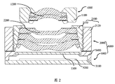
ステップ100:第1のサブレンズ部及び第2のサブアセンブリを準備する。図2は、本発明の1つの実施形態において、第1のサブレンズ部1000、第2のサブアセンブリ6000及びその初期配置位置を示す模式図である。図2を参照すると、前記第1のサブレンズ部1000は、第1の鏡筒1100及び少なくとも1つの第1のレンズ1200を含んでいる。本実施形態において、2つの第1のレンズ1200があり、他の実施例において、第1のレンズ1200は他の数、例えば、1つ、3つまたは4つ等であっても良いことは、理解しやすいことである。
Step 100: Prepare the first sublens section and the second subassembly. FIG. 2 is a schematic view showing a first
前記第2のサブアセンブリ6000は、互いに固定される第2のサブレンズ部2000及び感光アセンブリ3000を含んでいる。前記第2のサブレンズ部2000は、第2の鏡筒2100及び少なくとも1つの第2のレンズ2200を含んでいる。本実施形態において、3つの第2のレンズ2200があり、他の実施例において、第2のレンズ2200は他の数、例えば、1つ、2つまたは4つ等であっても良いことは、理解しやすいことである。本実施形態において、第2のサブレンズ部2000の第2の鏡筒2100は、一体に嵌設された内側鏡筒2110及び外側鏡筒2120(外側鏡筒2120はある時レンズ部ホルダーである)を含んでおり、前記内側鏡筒2110及び外側鏡筒は、ねじ連結されている。ねじ連結は、前記内側鏡筒2110と外側鏡筒2120との間の、唯一な連結方法ではないことに注意する必要がある。当然、その他の実施形態において、第2の鏡筒2100は一体化された鏡筒であっても良い。
The
図2も参照すると、1つの実施形態において、前記感光アセンブリ3000は、回路基板3100と、回路基板3100に実装された感光素子3200と、回路基板3100上に製造され、且つ、前記感光素子3200の周囲を取囲んだ筒状の支持体3400と、及び、支持体3400に実装されたフィルター素子3300とを備える。筒状の支持体3400は、内向き(感光素子3200に向けられた方向を指す)に延びている、鏡立としての延在部を備え、前記フィルター素子3300は前記延在部上に取り付けられる。前記筒状の支持体3400は上面をさらに備え、前記感光アセンブリは、当該上面により撮像モジュールの他のアセンブリ(例えば、第2のサブレンズ部2000)と互いに連結されることができる。当然、他の実施形態において、感光アセンブリ3000は、他の構造、例えば、前記感光アセンブリの回路基板に貫通孔を備え、感光素子が前記回路基板の貫通孔の中に実装されている構造、また、例えば、前記支持部がモールドにより、感光素子の周囲に形成されると共に、内向きに延伸し、且つ、前記感光素子に接触する(例えば、支持部は、前記感光素子のエッジ部の少なくとも一部の非感光領域に覆設されている)構造、さらに、例えば、前記感光アセンブリは前記フィルター素子を省略できる構造でも良いことを、理解しやすい。
Also referring to FIG. 2, in one embodiment, the
さらに、1つの実施形態において、非アクティブアライメントの方法により、前記第2のサブレンズ部2000と前記感光アセンブリ3000とを固定することによって、前記第2のサブアセンブリ6000を形成している。アクティブアライメントの英語名はActive Alignmentであり、AAと略することができる。非アクティブアライメントの方法は、アクティブアライメントの以外の方法を指す。例えば、1つの例において、機械的なアラインメント方法を採用し、前記第2のサブレンズ部2000と前記感光アセンブリ3000とを互いに固定させ、前記第2のサブアセンブリ6000を形成してもよい。
Further, in one embodiment, the
ステップ200:前記第1のサブレンズ部1000を前記第2のサブアセンブリ6000の光軸に配置し、前記少なくとも1つの第1のレンズ1200、及び、前記少なくとも1つの第2のレンズ2200を含む結像可能な光学系を構成する。本ステップにおいて、前記第1のサブレンズ部1000が前記第2のサブアセンブリ6000の光軸に配置することは、両方に対して初歩的な合わせを行い、1つの結像可能な光学系を形成することを指す。言い換えれば、全ての第1のレンズ1200と、全ての第2のレンズ2200とを含む光学系が結像可能であれば、本ステップの配置操作を完成したと見なすことができる。なお、サブレンズ部と感光アセンブリの製造過程において、いろんな製造公差またはその他の原因が存在するため、配置を完成した後、第1の鏡筒1100及び第2の鏡筒1200の中軸線は、必ずしも、光軸と重なるとは限らない。
Step 200: The first
ステップ300:前記光学系結像の実測解像度が最大化(実測解像度を向上し、予め設定した閾値に到達させることは、実測解像度の最大化を実現したと見なされることができる)になり、且つ、前記光学系結像の実測結像面の傾斜が最小化(実測結像面の傾斜を低減し、予め設定した閾値に到達させることは、実測結像面の傾斜の最小化を実現したと見なされることができる)になるように、前記第1のサブレンズ部1000の、前記第2のサブレンズ部2000に対する相対位置を調整する。第1のサブレンズ部1000と第2のサブレンズ部2000との間の相対位置の調整は、多自由度を含むことができる。
Step 300: The measured resolution of the optical system imaging is maximized (improving the measured resolution and reaching a preset threshold value can be regarded as achieving the maximization of the measured resolution), and , The inclination of the actually measured image plane of the optical system imaging is minimized (reducing the inclination of the actually measured image plane and reaching a preset threshold value has realized the minimization of the inclination of the actually measured image plane. The position of the first
図3は、本発明の1つの実施形態における相対位置の調整方法を示す図である。当該調整方法において、前記第1のサブレンズ部は、前記第2のサブレンズ部に対して、x、y、z方向に沿って移動する(即ち、当該実施形態における相対位置の調整は、3つの自由度を有する)。その内、z方向は光軸に沿う方向であり、x、y方向は光軸に垂直な方向である。x、y方向はいずれも1つの調整平面P内に位置し、当該調整平面P内での平行移動は、いずれもx、y方向で2つの成分に分解されることができる。 FIG. 3 is a diagram showing a method of adjusting a relative position in one embodiment of the present invention. In the adjustment method, the first sub-lens unit moves with respect to the second sub-lens unit in the x, y, and z directions (that is, the adjustment of the relative position in the embodiment is 3). Has one degree of freedom). Among them, the z direction is the direction along the optical axis, and the x and y directions are the directions perpendicular to the optical axis. Both the x and y directions are located in one adjustment plane P, and the translation within the adjustment plane P can be decomposed into two components in the x and y directions.
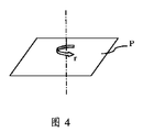
図4は、本発明の他の1つの実施形態における回転調整を示す図である。当該実施形態において、相対位置の調整は、図3における3つの自由度を有する以外に、回転自由度、即ち、r方向での調整がさらに追加されている。本実施形態において、r方向での調整は、前記調整平面P内での回転、即ち、前記調整平面Pに垂直な軸線を中心として回転することである。 FIG. 4 is a diagram showing rotation adjustment in another embodiment of the present invention. In this embodiment, the relative position adjustment has three degrees of freedom in FIG. 3, and a rotational degree of freedom, that is, an adjustment in the r direction is further added. In the present embodiment, the adjustment in the r direction is rotation in the adjustment plane P, that is, rotation about an axis perpendicular to the adjustment plane P.
さらに、図5は、本発明のまた1つの実施形態において、v、w方向での調整を追加した相対位置の調整方法を示す図である。v方向はxoz平面の回転角を表し、w方向はyoz平面の回転角を表し、v方向とw方向の回転角は、1つのベクトル角を合成することができ、このベクトル角は全体的な傾斜状態を表す。言い換えれば、v方向とw方向での調整により、第1のサブレンズ部の、第2のサブレンズ部に対する傾斜姿勢を調整することができる(即ち、前記第1のサブレンズ部の光軸の前記第2のサブレンズ部に対する光軸の傾斜である)。 Further, FIG. 5 is a diagram showing a method of adjusting the relative position in which adjustments in the v and w directions are added in another embodiment of the present invention. The v direction represents the rotation angle of the xoz plane, the w direction represents the rotation angle of the yoz plane, and the rotation angles of the v direction and the w direction can combine one vector angle, and this vector angle is the whole. Represents an inclined state. In other words, by adjusting in the v direction and the w direction, the tilted posture of the first sub-lens unit with respect to the second sub-lens unit can be adjusted (that is, the optical axis of the first sub-lens unit). The inclination of the optical axis with respect to the second sub-lens portion).
上述のx、y、z、r、v、wの6つの自由度の調整は、いずれも前記光学系の結像品質に影響する可能性がある(例えば、解像度の大きさに影響する)。本発明の他の実施形態において、相対位置の調整方法は、上述の6つの自由度における何れか1つのみを調整しても良く、そのうちの何れか2つ以上の組合わせでも良い。 Any of the above-mentioned adjustments of the six degrees of freedom of x, y, z, r, v, and w may affect the imaging quality of the optical system (for example, it affects the magnitude of the resolution). In another embodiment of the present invention, the method of adjusting the relative position may adjust only one of the above-mentioned six degrees of freedom, or may be a combination of any two or more of them.
さらに、1つの実施形態において、前記光学系結像の実測解像度を得る方法は、ステップ301とステップ302を含む。
ステップ301:参照視野及び/または測定視野に対応する複数のターゲットを設置する。例えば、中心視野を参照視野として選択し、1つまたは複数の興味を持つ領域に対応する視野を測定視野(例えば、80%の視野)として選択することができる。
ステップ302:前記感光アセンブリが出力する画像に基づいて、各々のターゲットに対応する解像度のデフォーカス曲線を獲得する。前記解像度のデフォーカス曲線により、視野に対応する実測解像度を獲得することができる。
Further, in one embodiment, the method of obtaining the measured resolution of the optical system imaging includes steps 301 and 302.
Step 301: Install a plurality of targets corresponding to the reference field of view and / or the measurement field of view. For example, the central field of view can be selected as the reference field of view, and the field of view corresponding to one or more regions of interest can be selected as the measurement field of view (eg, 80% field of view).
Step 302: Obtain a resolution defocus curve corresponding to each target based on the image output by the photosensitive assembly. With the defocus curve of the resolution, the measured resolution corresponding to the field of view can be obtained.
当該実施形態において、解像度はMTF(変調伝達関数)を用いて表すことができる。MTF値が高いほど解像度がより良いことを示す、このように、前記光学系結像の解像度は、前記感光アセンブリが出力する画像から得られたMTFデフォーカス曲線に基づいて、リアルタイムに獲得することができる。MTFデフォーカス曲線の変化情況に基づいて、現在、解像度の最大化状態に到達したか否かを判断することができる。図6は、本発明の1つの実施形態において、元の状態下でのMTFデフォーカス曲線を示す図である。その中には、中心視野のMTFデフォーカス曲線、及び、測定視野に位置する2つのターゲット結像のサジタル方向、及び、子午方向のMTFデフォーカス曲線が含まれている。 In this embodiment, the resolution can be expressed using an MTF (modulation transfer function). The higher the MTF value, the better the resolution. Thus, the resolution of the optical system imaging is acquired in real time based on the MTF defocus curve obtained from the image output by the photosensitive assembly. Can be done. Based on the changing situation of the MTF defocus curve, it is possible to determine whether or not the maximum resolution state has been reached at present. FIG. 6 is a diagram showing an MTF defocus curve under the original state in one embodiment of the present invention. It includes the MTF defocus curve in the central visual field, the sagittal direction of the two target images located in the measurement visual field, and the MTF defocus curve in the meridional direction.
他の一方、光学系の結像は結像面が傾く場合が多い。図9は、結像面の傾斜を示す模式図である。図9において、光軸に垂直な物体面はレンズを経て結像された後、傾斜した結像面を形成していることが分かる。中心視野からの入射光線はレンズを通過した後、中心焦点の位置にフォーカスし、軸外視野1からの入射光線はレンズを通過した後、周辺焦点1’の位置にフォーカスし、当該位置と中心焦点の位置との間には軸方向ズレD2を有し、軸外視野1’からの入射光線はレンズを通過した後、周辺焦点1の位置にフォーカスし、当該位置と中心焦点の位置との間には、軸方向ズレD1を有している。これは、感光素子の受光面が光軸に垂直的に配置される場合、周辺1と周辺1’の位置では、いずれも明瞭に結像することができない。図10は、中心位置と周辺1及び周辺1’位置での像の比較を示す模式図であり、周辺1及び周辺1’の位置の像は、何れも中心位置の像より明らかにぼやけていることが分かる。本発明では、第1のサブレンズ部と第2のサブレンズ部との間の傾斜角を調整することによって、上述の結像面の傾斜を補償する。
On the other hand, in the image formation of the optical system, the image plane is often tilted. FIG. 9 is a schematic view showing the inclination of the image plane. In FIG. 9, it can be seen that the object surface perpendicular to the optical axis forms an inclined image forming surface after being imaged through the lens. The incident light ray from the central visual field passes through the lens and then focuses on the position of the central focal point, and the incident light ray from the off-axis
1つの実施形態において、実測結像面の傾斜を得る方法は、ステップ303とステップ304を含む。
ステップ303:何れか1つの測定視野(例えば、80%の視野)に対して、当該測定視野の異なる測定位置に対応する、複数のターゲットを設置する。図14は、1つの実施形態において、ターゲットの設置方法の例を示す図である。図14に示すように、測定視野は80%の視野であり、4つのターゲットはそれぞれスタンダード版の四隅に設置されている。
In one embodiment, the method of obtaining the inclination of the measured image plane includes steps 303 and 304.
Step 303: For any one measurement field of view (for example, 80% field of view), a plurality of targets corresponding to different measurement positions of the measurement field of view are installed. FIG. 14 is a diagram showing an example of a target installation method in one embodiment. As shown in FIG. 14, the measurement field of view is 80% field of view, and each of the four targets is installed at the four corners of the standard version.
ステップ304:前記感光アセンブリが出力する画像に基づいて、同一視野の異なる位置に対応する、各々解像度のデフォーカス曲線を得る。これらの解像度のデフォーカス曲線が、横座標軸(光軸方向に沿うデフォーカス量の座標軸を表す)に集まる場合、当該測定視野に対応する、結像面傾斜が補償されたことを示し、即ち、前記実測結像面の傾斜を最小化することは、当該測定視野において実現されている。1つの実施形態において、測定視野の異なる測定位置に対応する解像度のデフォーカス曲線のピーク値の前記光軸方向で位置ズレが低減し、対応する閾値に到達したことは、当該測定視野に対応する結像面の傾斜が補償されたことを示す。 Step 304: Based on the image output by the photosensitive assembly, defocus curves of different resolutions corresponding to different positions in the same field of view are obtained. When the defocus curves of these resolutions are gathered on the horizontal coordinate axis (representing the coordinate axis of the defocus amount along the optical axis direction), it indicates that the curvature of field corresponding to the measurement field of view has been compensated, that is, Minimizing the inclination of the actually measured image plane is realized in the measurement field of view. In one embodiment, the fact that the positional deviation of the peak value of the defocus curve of the resolution corresponding to the different measurement positions of the measurement field of view is reduced in the optical axis direction and the corresponding threshold value is reached corresponds to the measurement field of view. It indicates that the inclination of the image plane has been compensated.
さらに、1つの実施形態において、前記ステップ300は以下のサブステップを含む。
ステップ310:前記光学系結像の実測解像度を向上し、対応する閾値に到達するように、前記第1のサブレンズ部1000を、前記第2のサブレンズ部2000に対して調整平面Pに沿って移動させる。以上、x、y、z、r、v、wの6つの自由度の調整を説明している。x、y方向での平行移動、及びr方向での回転は、本ステップにおいて、調整平面Pに沿う移動と見なすことができる。本ステップにおいて、参照視野及び測定視野に対応する複数のターゲットを設置し、その後、前記感光アセンブリが出力する画像に基づいて、各々のターゲットに対応する解像度のデフォーカス曲線を獲得する。前記第1のサブレンズ部1000を前記第2のサブレンズ部2000に対して、x、y、及びr方向上で移動させることによって、参照視野のターゲット結像に対応する解像度のデフォーカス曲線のピーク値を向上し、対応する閾値に到達させる。参照視野は中心視野を選択することができるが、参照視野は中心視野に限らず、一部の実施形態において、他の視野を参照視野として選択できる、ことに注意する必要がある。本ステップにおいて、前記対応する閾値に到達することとは、参照視野のターゲット結像に対応する解像度のデフォーカス曲線のピーク値を向上し、対応する閾値に到達させることである。
Further, in one embodiment, the
Step 310: The first
図7は、ステップ310で調整されたMTFデフォーカス曲線の例を示す図である。調整の後、2つのターゲット結像のサジタル方向、及び、子午方向のMTF値は、いずれも明確に向上されていることが分かる。図8は、本発明の他の1つの実施形態において、ステップ310で調整された第1のサブレンズ部1000及び第2のサブアセンブリ6000及びそれらの位置関係を示す図である。第1のサブレンズ部1000の中軸線は、第2のサブレンズ部2000の中軸線に対して、x方向上で△xズレていることが分かる。なお、図8は単なる例示である。図8には、y方向上でのズレを示していないが、当業者がわかるように、第1のサブレンズ部1000の中軸線は、第2のサブレンズ部2000の中軸線に対して、y方向上でも△yのズレを有してもよい。
FIG. 7 is a diagram showing an example of the MTF defocus curve adjusted in step 310. After the adjustment, it can be seen that the MTF values in the sagittal direction and the meridional direction of the two target images are clearly improved. FIG. 8 is a diagram showing the
ステップ320:測定視野の前記光学系結像の実測解像度を向上し、対応する閾値に到達させ、且つ、測定視野の前記光学系結像の実測結像面の傾斜を低減し、対応する閾値に到達させるように、前記第1のサブレンズ部1000の軸線を、前記第2のサブレンズ部2000の軸線に対して傾斜させる。v、w方向上での回転は、本ステップの傾斜調整に対応する。本ステップにおいて、前記の実測解像度を対応する閾値に到達させることは、当該測定視野の異なる測定位置に対応する、複数のターゲットが結像した、解像度のデフォーカス曲線のピーク値における、最も小さい1つ値を向上させ、対応する閾値に到達させることを含む。他の実施形態において、前記の実測解像度を対応する閾値に到達させることは、当該測定視野の異なる測定位置に対応する、前記複数のターゲットが結像した解像度のデフォーカス曲線のピーク値の均一性を向上させ、対応する閾値に到達させることを、さらに含む。前記の均一性を向上させることは、当該測定視野の前記複数のターゲット結像に対応する、解像度のデフォーカス曲線のピーク値の分散を低減し、対応する閾値に到達させることを含む。測定視野の前記光学系結像の実測結像面の傾斜を低減し、対応する閾値に到達させることは、測定視野の異なる測定位置に対応する、解像度のデフォーカス曲線のピーク値の、前記光軸方向での位置ズレを低減させ、対応する閾値に到達させることを含む。
Step 320: Improve the measured resolution of the optical system imaging of the measurement field of view to reach the corresponding threshold value, and reduce the inclination of the measured imaging surface of the optical system imaging of the measurement field of view to the corresponding threshold value. The axis of the first
図11は、本発明の1つの実施形態において、ステップ320で調整されたMTFデフォーカス曲線を示す図である。図12は、本発明の1つの実施形態において、ステップ320で調整された第1のサブレンズ部及び第2のサブレンズ部の相対位置関係を示す図である。図12において、第1のサブレンズ部の中軸線は、第2のサブレンズ部の中軸線に対して、x方向上で△xズレており、第1のサブレンズ部1000の中軸線は、前記第2のサブレンズ部2000の中軸線に対して、△v2傾いている。図12には、w方向上での傾斜が示されていないが、当業者がわかるように、w方向での感光アセンブリ3000の軸線は、第2のサブレンズ部2000の中軸線に対して、傾斜角を有してもよい。
FIG. 11 is a diagram showing an MTF defocus curve adjusted in step 320 in one embodiment of the present invention. FIG. 12 is a diagram showing the relative positional relationship between the first sub-lens portion and the second sub-lens portion adjusted in step 320 in one embodiment of the present invention. In FIG. 12, the central axis of the first sub-lens portion is deviated by Δx in the x direction with respect to the central axis of the second sub-lens portion, and the central axis of the
ステップ400:前記第1のサブレンズ部1000、及び、前記第2のサブレンズ部2000の相対位置が変化しないように、前記第1のサブレンズ部1000と前記第2のサブレンズ部2000とを接続する。図13は、本発明の1つの実施形態において、接続した後に形成された撮像モジュールを示す図である。
Step 400: The
第1のサブレンズ部と第2のサブレンズ部とを接続するプロセスは、情況に応じて選択することができる。例えば、1つの実施形態において、粘着プロセスにより、第1のサブレンズ部と第2のサブレンズ部とを接続し、図13に示すように、当該実施形態において、接着剤4000により、第1のサブレンズ部1000と第2のサブレンズ部2000とを接着する。他の1つの実施形態において、レーザー溶接プロセスにより、第1のサブレンズ部と第2のサブレンズ部とを接続する。また1つの実施形態において、超音波溶接プロセスにより、第1のサブレンズ部と第2のサブレンズ部とを接続する。上述のプロセス以外に、他の溶接プロセスも提供し選択することができる。なお、本発明において、「接続」という言葉は、直接的に接続することに限らない。例えば、1つの実施形態において、第1のサブレンズ部と第2のサブレンズ部は、媒介物(当該媒介物は、剛性の媒介物でも良い)により接続されることができ、このように媒介物による接続は、第1のサブレンズ部と第2のサブレンズ部との間(感光アセンブリ及び第2のサブレンズ部との間)の相対位置(相対距離及び姿勢を含む)を一定に維持できれば、用語「接続」に含まれる。
The process of connecting the first sub-lens unit and the second sub-lens unit can be selected according to the situation. For example, in one embodiment, the first sub-lens portion and the second sub-lens portion are connected by an adhesive process, and as shown in FIG. 13, in the embodiment, the first sub-lens portion is used by the adhesive 4000. The
前記実施形態の撮像モジュールの組立て方法は、撮像モジュールの解像度を向上させ、大量に生産した撮像モジュールの工程能力指数(CPK)を向上させ、光学結像レンズ部、及び、モジュールの各々素子の精度、及び、その組立て精度に対する要求を緩和し、光学結像レンズ部、及び、モジュールの全体コストを低減させ、組立過程において、撮像モジュールの各種収差に対してリアルタイム調整することができ、よって、結像品質のばらつきを低減し、不良率を低減し、生産コストを低減し、結像品質を向上させることができる。 The method of assembling the imaging module of the above embodiment improves the resolution of the imaging module, improves the process capability index (CPK) of the mass-produced imaging module, and improves the accuracy of the optical imaging lens unit and each element of the module. And, the requirement for the assembly accuracy is relaxed, the overall cost of the optical imaging lens unit and the module is reduced, and various aberrations of the imaging module can be adjusted in real time during the assembly process. It is possible to reduce the variation in image quality, reduce the defect rate, reduce the production cost, and improve the image quality.
さらに、ほかの1つの実施形態において、前記ステップ300は、前記第1のサブレンズ部を前記第2のサブレンズ部に対して、前記光軸方向上で移動させ、前記光学系結像の実測結像面を目標面にマッチングすることをさらに含む。以上、x、y、z、r、v、wの6つの自由度の調整を説明している。そのなか、z方向上での移動は、本ステップにおける前記光軸方向上での移動として見なすことができる。
Further, in another embodiment, in the
組立された光学レンズ部には、1つの所望の結像面があり、本明細書ではこの所望の結像面を目標面と称す。一部の情況下で、目標面は平面である。例えば、光学レンズ部が対応する撮像モジュールの感光素子の感光面が平面である場合、最も良い結像品質に達するために、前記光学レンズ部の所望の結像面も平面であり、言い換えれば、この時の目標面は平面である。他の一部の情況下で、前記目標面は凸形状または凹形状の曲面、または波形の曲面でも良い。例えば、光学レンズ部に対応する撮像モジュールの感光素子の感光面が凸形状、または、凹形状の曲面である場合、最も良い結像品質に達するために、目標面も凸形状または凹形状の曲面であり、光学レンズ部に対応する撮像モジュールの感光素子の感光面が、波形の曲面である場合、目標面も波形の曲面である。 The assembled optical lens unit has one desired image plane, and this desired image plane is referred to as a target surface in the present specification. Under some circumstances, the target plane is flat. For example, when the photosensitive surface of the photosensitive element of the imaging module corresponding to the optical lens unit is flat, the desired imaging surface of the optical lens unit is also flat in order to reach the best imaging quality, in other words. The target surface at this time is a flat surface. Under some other circumstances, the target plane may be a convex or concave curved surface, or a corrugated curved surface. For example, when the photosensitive surface of the photosensitive element of the imaging module corresponding to the optical lens portion is a convex or concave curved surface, the target surface is also a convex or concave curved surface in order to reach the best imaging quality. When the photosensitive surface of the photosensitive element of the imaging module corresponding to the optical lens unit is a curved surface of a waveform, the target surface is also a curved surface of the waveform.
1つの実施形態において、前記感光素子が出力する画像に基づいて、実測結像面が目標面とマッチングするか否かを判断する。前記実測結像面が目標面とマッチングするステップにおいて、前記実測結像面が目標面とマッチングすることは、前記感光素子が出力する画像からモジュールの実測像面湾曲を得ることにより、前記モジュール実測像面湾曲を+/−5μmの範囲内にすることである。当該実施形態では、撮像モジュールの結像品質をさらに向上させることができる。 In one embodiment, it is determined whether or not the actually measured image plane matches the target surface based on the image output by the photosensitive element. In the step of matching the actually measured image plane with the target surface, matching the actually measured image plane with the target surface means that the module actually measured curvature of field is obtained from the image output by the photosensitive element. The curvature of field should be within the range of +/- 5 μm. In this embodiment, the imaging quality of the imaging module can be further improved.
さらに、1つの実施形態において、前記ステップ320で、選択された測定視野に対して、ペアでターゲットを設置する。例えば、第1の方向には、夫々中心位置の両端に位置する一対の第1のターゲットを設置し、第2の方向には、夫々中心位置の両端に位置する一対の第2のターゲットを設置する。図14に示すように、測定視野は80%の視野でり、4つのターゲットは夫々スタンダード版の四隅に設置されている。左下及び右上の2つのターゲットは、第1の方向上での一対の第1のターゲットとすることができ、左上及び右下の2つのターゲットは、第2方向上での一対の第2のターゲットとすることができる。前記一対の第1のターゲットの解像度デフォーカス曲線が横座標軸方向(即ち、光軸方向上)での偏移ベクトルに基づいて、前記光学系結像の実測結像面の、第1の方向における傾斜成分を判断することができ、前記一対の第2のターゲットの解像度のデフォーカス曲線が横座標軸方向での偏移ベクトルに基づいて、前記光学系結像の実測結像面の、第2の方向上での傾斜成分を判断することができる。その後、前記第1サブレンズ部の、前記第2のサブレンズ部に対する姿勢を調整することによって、前記第1のサブレンズ部の軸線の、前記第2のサブレンズ部の軸線に対する夾角を変化させ、前記第1の方向上での傾斜成分、及び、前記第2の方向上での傾斜成分を補償する。 Further, in one embodiment, in step 320, the targets are set in pairs with respect to the selected measurement field of view. For example, in the first direction, a pair of first targets located at both ends of the center position are installed, and in the second direction, a pair of second targets located at both ends of the center position are installed. do. As shown in FIG. 14, the measurement field of view is 80%, and each of the four targets is installed at the four corners of the standard version. The lower left and upper right two targets can be a pair of first targets in the first direction, and the upper left and lower right two targets are a pair of second targets in the second direction. Can be. The resolution defocus curve of the pair of first targets is in the first direction of the actually measured imaging plane of the optical system imaging based on the deviation vector in the horizontal coordinate axis direction (that is, on the optical axis direction). The tilt component can be determined, and the defocus curve of the resolution of the pair of second targets is the second of the actually measured imaging plane of the optical system imaging based on the deviation vector in the horizontal coordinate axis direction. It is possible to determine the inclination component in the direction. After that, by adjusting the posture of the first sub-lens unit with respect to the second sub-lens unit, the angle of the axis of the first sub-lens unit with respect to the axis of the second sub-lens unit is changed. , The tilt component in the first direction and the tilt component in the second direction are compensated.
さらに、1つの実施形態において、前記ステップ310では、前記第1のサブレンズ部を前記第2のサブレンズ部に対して、前記調整平面に沿って、第1の範囲内で移動させ、
前記ステップ320では、実測結像面の傾斜を予め設定した区間内に低下できない場合、実測結像面の傾斜が予め設定した区間内に低下するまで、再調整ステップ330をさらに実行し、
なお、前記再調整ステップ330は、以下のステップ331とステップ332とを含む。
ステップ331:前記第1のサブレンズ部を前記第2のサブレンズ部に対して、前記調整平面に沿って第2の範囲内で移動させる。前記第2の範囲は第1の範囲より小さく、言い換えれば、ステップ310に対して、ステップ331では、小さい範囲内の調整平面上で、第1のサブレンズ部と第2のサブレンズ部の相対位置に対して調整を行う。一方、調整の範囲が比較的に小さいため、ステップ310での調整により、到達した実測解像度が基本的に維持させ、他の一方、結像面の傾斜がステップ332で補償されるように、結像面の傾斜度合いを低減することができる。
Further, in one embodiment, in step 310, the first sub-lens portion is moved with respect to the second sub-lens portion along the adjustment plane within the first range.
In step 320, if the inclination of the actually measured image plane cannot be reduced within the preset section, readjustment step 330 is further executed until the inclination of the actually measured image plane is reduced within the preset section.
The readjustment step 330 includes the following steps 331 and 332.
Step 331: The first sub-lens portion is moved with respect to the second sub-lens portion within the second range along the adjustment plane. The second range is smaller than the first range, in other words, in step 331, relative to the first sublens section and the second sublens section on the adjustment plane within the small range with respect to step 310. Make adjustments to the position. On the other hand, since the range of adjustment is relatively small, the adjustment in step 310 basically maintains the measured resolution reached, and on the other hand, the inclination of the image plane is compensated in step 332. The degree of inclination of the image plane can be reduced.
ステップ332:前記感光素子により得られた、前記光学系結像の実測結像面の傾斜を低減し、対応する閾値に到達させるように、前記第1のサブレンズ部の中軸線が、前記第2のサブレンズ部の中軸線に対する夾角を調整する。実測結像面の傾斜を予め設定した区間内に低減できない場合、実測結像面の傾斜を予め設定した区間内に低下させるまで、上述ステップ331と332を循環的に実行する。 Step 332: The central axis of the first sub-lens portion is the first so as to reduce the inclination of the actually measured imaging surface of the optical system imaging obtained by the photosensitive element and reach the corresponding threshold value. Adjust the threshold angle with respect to the central axis of the sub-lens portion of 2. If the inclination of the actually measured image plane cannot be reduced within the preset section, the steps 331 and 332 described above are cyclically executed until the inclination of the actually measured image plane is reduced within the preset section.
本発明の1つの実施形態において、前記撮像モジュールの組立方法に対応する、撮像モジュールをさらに提供している。図15は、当該実施形態における撮像モジュールを示す図である。図15を参照すると、当該撮像モジュールは、第1のサブレンズ部1000及び第2のサブアセンブリ6000を備えている。第1のサブレンズ部1000は、第1の鏡筒1100及び少なくとも1つの第1のレンズ1200を備えている。第2のサブアセンブリ6000は、互いに固定される第2のサブレンズ部2000及び感光アセンブリ3000を備えており、前記第2のサブレンズ部2000は、第2の鏡筒2100及び少なくとも1つの第2のレンズ2200を備えており、前記感光アセンブリ3000は感光素子3300を備えている。
In one embodiment of the present invention, an image pickup module corresponding to the method of assembling the image pickup module is further provided. FIG. 15 is a diagram showing an imaging module in the embodiment. Referring to FIG. 15, the imaging module includes a
前記第1のサブレンズ部1000は、前記第2のサブレンズ部2000の光軸に配置されることにより、前記少なくとも1つの第1のレンズ1200、及び、前記少なくとも1つの第2のレンズ2200を含む結像可能な光学系を構成している。
前記第1のサブレンズ部1000及び前記第2のサブレンズ部2000は、接続媒体4000により互いに固定されており、且つ、前記接続媒体4000は、前記第1のサブレンズ部1000の中軸線が前記第2のサブレンズ部2000の中軸線に対して、0.5度より小さい傾斜角を有するように構成されている。前記接続媒体4000は、さらに、前記第1のサブレンズ部1000と、前記第2のサブレンズ部2000との相対位置が変化しないように構成され、且つ、前記相対位置は、前記感光素子3300により得られた、前記光学系結像の実測解像度を向上し、第1の閾値に到達させ、及び、前記感光素子3300により得られた、前記光学系結像の実測結像面の傾斜を低減し、第2の閾値に到達させる。
The first
The first
1つの実施形態において、接続媒体は粘着材または溶接シート(例えば、金属シート)でも良く、第2の接続媒体は粘着材または溶接シート(例えば、金属シート)でも良い。第1のサブレンズ部と第2のサブレンズ部を接続し、両方を互いに固定させる接続媒体は、第1のサブレンズ部の一部でも、第2のサブレンズ部の一部でもない。 In one embodiment, the connecting medium may be an adhesive or a welded sheet (eg, a metal sheet) and the second connecting medium may be an adhesive or a welded sheet (eg, a metal sheet). The connection medium that connects the first sub-lens portion and the second sub-lens portion and fixes both to each other is neither a part of the first sub-lens portion nor a part of the second sub-lens portion.
1つの実施形態において、前記接続媒体は、前記第1のサブレンズ部の中軸線と、前記第2のサブレンズ部の中軸線とを0〜15μmずらすように構成されている。 In one embodiment, the connection medium is configured to shift the central axis of the first sub-lens portion and the central axis of the second sub-lens portion by 0 to 15 μm.
1つの実施形態において、前記接続媒体は、さらに前記第1のサブレンズ部と、第2のサブレンズ部との間に構造的隙間を有するように構成されている。第1のサブレンズ部1000及び第2のサブレンズ部2000は、何れも光学面及び構造面を有する。レンズ部において、光学面は、レンズ上の有効光線が通過する面である。レンズ上の光学面ではない面は構造面である。鏡筒に位置する面は何れも構造面である。構造的隙間は構造面との間の隙間である。
In one embodiment, the connection medium is further configured to have a structural gap between the first sublens portion and the second sublens portion. Both the first
さらに、1つの実施形態において、前記第2のサブレンズ部2000と、前記感光アセンブリ3000とは、機械的な合わせ方法により組立されており、前記第2のサブアセンブリ6000を形成している。前記第2のサブレンズ部2000と前記感光アセンブリ3000との間には、10〜50μmの機械的な合わせに適用する隙間5000を有している。
Further, in one embodiment, the
本明細書において、第1のサブレンズ部の中軸線と第2のサブレンズ部の中軸線が複数記載されている。図16を参照すると、便利に測量するために、第1のサブレンズ部1000の中軸線は、第1のサブレンズ部1000において、第2のサブレンズ部2000に最も接近する光学面1201の中軸線として理解することができ、第2のサブレンズ部2000に最も接近する第1のレンズ1200の構造面1202により画定される中軸線として理解することもでき、第1のサブレンズ部1000の第1のレンズ1200と第1の鏡筒1100とが締り嵌めする場合、第1のサブレンズ部1000の中軸線は、第1の鏡筒の内側面により画定される中軸線として理解することもできる。
In this specification, a plurality of central axes of the first sub-lens portion and a plurality of central axes of the second sub-lens portion are described. Referring to FIG. 16, for convenient measurement, the central axis of the first
類似的に、便利に測量するために、第2のサブレンズ部2000の中軸線は、第2のサブレンズ部2000において、第1のサブレンズ部1000に最も接近する光学面2201の中軸線として理解することができ、第1のサブレンズ部1000に最も接近する第2レンズ2200の構造面2202により画定される中軸線として理解することもでき、第2のサブレンズ部2000の第2のレンズ2200と第2の鏡筒とが締り嵌めする場合、第2のサブレンズ部2000の中軸線は、第2の鏡筒の内側面により画定される中軸線として理解することもできる。
Similarly, for convenient measurement, the central axis of the
本発明は、特に、レンズ部の直径が10mmより小さい、スマート端末用の撮像モジュールの小型化に適合する。1つの実施形態において、前記第1のサブレンズ部及び前記第2のサブレンズ部の外側面には、機械アーム(またはその他の把持装置)は当該接触面を介して、前記第1のサブレンズ部及び前記第2のサブレンズ部で便利に把持(たとえば、挟持又は吸着)し、第1のサブレンズ部と第2のサブレンズ部との間の、相対位置に対する正確な調整を実現するように、いずれも充分な接触面を有する。このような正確な調整は、6つの自由度の調整であっても良い。調整刻み幅はマイクロメーターレベル以下に達することができる。 The present invention is particularly suitable for miniaturization of image pickup modules for smart terminals in which the diameter of the lens portion is smaller than 10 mm. In one embodiment, a mechanical arm (or other gripping device) is placed on the outer surfaces of the first sublens portion and the second sublens portion via the contact surface of the first sublens. Conveniently gripped (for example, pinched or sucked) by the portion and the second sub-lens portion to realize accurate adjustment with respect to the relative position between the first sub-lens portion and the second sub-lens portion. In addition, each has a sufficient contact surface. Such an accurate adjustment may be an adjustment of six degrees of freedom. The adjustment step size can reach below the micrometer level.
さらに、1つの実施形態において、前記第2のサブレンズ部2000は、携帯電話の撮像モジュールのオートフォーカスを実現するために、モーターをさらに備えてもよい。図16は、本発明の1つの実施形態において、組立したモーター付きの、且つ、モーターがオフ状態での撮像モジュールを示す図である。図17は、本発明の1つの実施形態において、組立したモーター付きの、且つ、モーターがオン状態での撮像モジュールを示す図である。当該実施例において、モーターは、モーターベース2310及びモーターベース2310に実装されたモーター支持体2320を備えている。前記モーター支持体2320は、前記第2の鏡筒2100を取囲んでおり、モーターの駆動機構(図に示しておらず)は、当該モーター支持体2320に取り付けられる。モーター支持体2320は、板バネ2330を介して第2の鏡筒2100を接続している。駆動機構がオンになる場合、第2のサブ鏡筒は光軸に沿って移動し、板バネ2330は変形する(図17に示す)。ステップ310及びステップ320において、モーター、第2の鏡筒2100及び第2の鏡筒2100に取り付けられる第2のレンズ2200は、全体的に第2のサブレンズ部2000として移動及び調整が行われる。ステップ500において、モーターベース2310を感光アセンブリ3000に接続することによって、前記第2のサブレンズ部2000と感光アセンブリ3000との接続を実現する。さらに、ステップ310において、第1のサブレンズ部と第2のレンズとの相対位置を調整する場合、モーターをオン状態に保持させ(例えば、モーターへの通電をモーターのオンと見なすことができる)、このように、得られた実測解像度はモーターがオン状態での実測解像度である。ステップ320において、感光アセンブリの、第2のサブレンズ部の中軸線に対する傾斜角を調整する際、モーターをオン状態に保持させ、このように、得られた実測結像面の傾斜は、モーターがオン状態での実測結像面の傾斜である。モーターをオンにした後、板バネは相応的に変形する。しかしながら、モーターのオフ状態に対して、モーターのオンによる板バネの変形は、第2のサブ鏡筒の中軸の、第1のサブレンズ部の中軸に対する余分の傾斜を発生する可能性がある(図17の傾斜角△v4を参照)。本実施形態の構成は、モーターのオンにより招く第2の鏡筒の余分の傾斜を、ステップ310及びステップ320の調整において、合わせて補償することができ、よって、オートフォーカス撮像モジュールの結像品質をさらに向上させる。
Further, in one embodiment, the
以上の説明は、本願の好ましい実施形態及び使用される技術原理に対する説明のみである。本願に関する発明の範囲は、上述の技術的特徴の特定の組合せにより形成された技術案に限定されず、同時に、前記発明の構想を逸脱しない限り、上述の技術特徴、または、その同等の特徴を任意に組合せて形成された他の技術案をカバーすべきことを、当業者は理解するはずである。例えば、上述の特徴は、本願に開示されている(ただし、これに限らない)類似の機能を有する技術的特徴と、互いに置き換えて形成された技術案である。 The above description is only a description of the preferred embodiments of the present application and the technical principles used. The scope of the invention relating to the present application is not limited to the technical proposal formed by a specific combination of the above-mentioned technical features, and at the same time, the above-mentioned technical features or equivalent features are used as long as the concept of the present invention is not deviated. Those skilled in the art should understand that other technical proposals formed in any combination should be covered. For example, the above-mentioned features are technical features having similar functions disclosed in the present application (but not limited to this), and technical proposals formed by replacing each other.
Claims (17)
前記少なくとも1つの第1のレンズと、前記少なくとも1つの第2のレンズとを含む結像可能な光学系を構成するように、前記第1のサブレンズ部を前記第2のサブレンズ部の光軸に配置するステップと、
前記感光素子により得られた前記光学系結像の実測解像度を向上し、第1の閾値までに到達させ、且つ、前記感光素子により得られた実測結像面の傾斜を低減し、第2の閾値までに到達させるように、前記第1のサブレンズ部の前記第2のサブレンズ部に対する相対位置を調整するステップと、
前記第1のサブレンズ部と前記第2のサブレンズ部との相対位置が変化しないように、前記第1のサブレンズ部と前記第2のサブレンズ部とを接続するステップとを含み、
前記第1のサブレンズ部の、前記第2のサブレンズ部に対する相対位置を調整するステップは、
前記感光素子により得られた前記光学系結像の、参照視野における実測解像度を向上し、対応する閾値までに到達させるように、前記第1のサブレンズ部を前記第2のサブレンズ部に対して、調整平面に沿って移動させるサブステップと、前記感光素子により得られた前記光学系結像の、測定視野における実測解像度を向上し、対応する閾値までに到達させ、且つ、前記感光素子により得られた測定視野の実測結像面の傾斜を低減し、前記第2の閾値までに達させるように、前記第1のサブレンズ部の軸線の、前記第2のサブレンズ部の軸線に対する夾角を調整するサブステップとを含む、ことを特徴とする撮像モジュールの組立方法。 The second sublens section includes a first sublens section including a first lens barrel and at least one first lens, a second sublens section fixed to each other, and a photosensitive assembly, and the second sublens section is a second. A step of preparing a second subassembly, which comprises a lens barrel and at least one second lens, wherein the photosensitive assembly comprises a photosensitive element.
The light of the second sub-lens unit is used to form the first sub-lens unit so as to form an image-capable optical system including the at least one first lens and the at least one second lens. Steps to place on the axis and
The measured resolution of the optical system imaging obtained by the photosensitive element is improved to reach the first threshold value, and the inclination of the measured imaging surface obtained by the photosensitive element is reduced. A step of adjusting the relative position of the first sub-lens unit with respect to the second sub-lens unit so as to reach the threshold value, and
Wherein as the first sub lens unit relative positions of the second sub lens unit does not change, seen including a step of connecting the second sub lens unit and the first sub lens unit,
The step of adjusting the relative position of the first sub-lens unit with respect to the second sub-lens unit is
The first sub-lens unit is attached to the second sub-lens unit so as to improve the measured resolution of the optical system imaging obtained by the photosensitive element in the reference field of view and reach the corresponding threshold value. The sub-step to move along the adjustment plane and the measured resolution of the optical system imaging obtained by the photosensitive element in the measurement field of view are improved to reach the corresponding threshold value, and the photosensitive element The angle of the axis of the first sub-lens section with respect to the axis of the second sub-lens section so as to reduce the inclination of the actually measured image pickup surface of the obtained measurement field of view and reach the second threshold value. including a sub-step of adjusting the assembling process of the imaging module, characterized in that.
前記感光素子により得られた前記光学系結像の実測結像面が、目標面とマッチングするように、前記第1のサブレンズ部を前記第2のサブレンズ部に対して、前記光軸方向に沿うZ方向上で移動させるステップを含む、ことを特徴とする請求項1に記載の撮像モジュールの組立方法。 The step of adjusting the relative position of the first sub-lens unit with respect to the second sub-lens unit is
The first sub-lens unit is oriented in the optical axis direction with respect to the second sub-lens unit so that the actually measured image plane of the optical system image obtained by the photosensitive element matches the target surface. assembling method of the imaging module of claim 1 comprising the step of moving in the Z direction, characterized in that along.
測定視野に対して、当該測定視野の異なる測定位置に対応する複数のターゲットを設置することと、
前記感光アセンブリが出力する画像に基づいて、各測定位置に対応する、解像度のデフォーカス曲線を獲得することとを含む、ことを特徴とする請求項1に記載の撮像モジュールの組立方法。 The method of obtaining the inclination of the measured image plane is
To set multiple targets corresponding to different measurement positions in the measurement field of view,
On the basis of the image photosensitive assembly output, corresponding to each measurement position, the assembling method of the imaging module of claim 1 including the to win defocus curve resolution, characterized in that.
参照視野と測定視野の複数の異なる測定位置に対応するターゲットを設置することと、
前記感光アセンブリが出力する画像に基づいて、各測定位置に対応する解像度のデフォーカス曲線を獲得することとを含む、ことを特徴とする請求項1に記載の撮像モジュールの組立方法。 The method for obtaining the measured resolution of the optical system imaging is
Setting targets corresponding to multiple different measurement positions in the reference field of view and the measurement field of view,
On the basis of the image photosensitive assembly output, the assembling method of the imaging module of claim 1 including the to win defocus curve of resolution corresponding to each measurement position, be characterized.
前記感光素子によって得られた前記光学系結像の、参照視野における実測解像度を向上させ、対応する閾値に達するように、前記第1のサブレンズ部を前記第2のサブレンズ部に対して、調整平面に沿って第1の範囲内で移動させるサブステップと、
その後、前記第1のサブレンズ部の軸線の、前記第2のサブレンズ部の軸線に対する夾角を調整することにより、前記感光素子により得られた前記光学系結像の、測定視野における実測解像度を向上し、対応する閾値に到達させ、且つ、前記感光素子により得られた測定視野での実測結像面の傾斜を低減させ、実測結像面の傾斜が前記第2の閾値に到達しない場合、実測結像面の傾斜を減少し、前記第2の閾値に到達するまで、再調整ステップをさらに実行するサブステップと、を含み、
前記再調整ステップは、
前記第1のサブレンズ部を、前記第2のサブレンズ部に対して前記調整平面に沿って、第1の範囲より小さい第2の範囲内で移動するステップと、
前記感光素子により得られた前記光学系結像の実測結像面の傾斜を低減させるように、前記第1のサブレンズ部の中軸線の、前記第2のサブレンズ部の中軸線に対する夾角を調整するステップとを含む、ことを特徴とする請求項1に記載の撮像モジュールの組立方法。 The step of adjusting the relative position of the first sub-lens unit with respect to the second sub-lens unit is
The first sub-lens unit is attached to the second sub-lens unit so as to improve the measured resolution in the reference field of view of the optical system imaging obtained by the photosensitive element and reach the corresponding threshold value. Substeps to move within the first range along the adjustment plane,
After that, by adjusting the angle of the axis of the first sub-lens section with respect to the axis of the second sub-lens section, the measured resolution of the optical system image formation obtained by the photosensitive element in the measurement field of view can be obtained. When it is improved, the corresponding threshold is reached, and the inclination of the actually measured image plane in the measurement field of view obtained by the photosensitive element is reduced, and the inclination of the actually measured image plane does not reach the second threshold. Includes a sub-step that reduces the tilt of the measured image plane and further performs the readjustment step until the second threshold is reached.
The readjustment step
A step of moving the first sub-lens portion with respect to the second sub-lens portion along the adjustment plane within a second range smaller than the first range.
The angle of the central axis of the first sublens section with respect to the central axis of the second sublens section is set so as to reduce the inclination of the actually measured imaging surface of the optical system image pickup obtained by the photosensitive element. The method for assembling an image pickup module according to claim 1, further comprising an adjustment step.
第1の鏡筒及び少なくとも1つの第1のレンズを含む第1のサブレンズ部と、
互いに固定される第2のサブレンズ部と感光アセンブリとを含み、前記第2のサブレンズ部は第2の鏡筒と少なくとも1つの第2のレンズとを含み、前記感光アセンブリは感光素子を含む、第2のサブアセンブリとを備え、
前記第1のサブレンズ部は、前記第2のサブレンズ部の光軸に配置され、前記少なくとも第1のレンズと前記少なくとも1つの第2のレンズとを含む結像可能な光学系を構成しており、
前記第1のサブレンズ部と前記第2のサブレンズ部とは、接続媒体により互いに固定されており、且つ、前記接続媒体は、前記第1のサブレンズ部の中軸線が前記第2のサブレンズ部の中軸線に対して、傾斜角を有するように構成されている、ことを特徴とする撮像モジュール。 Created by any one of the methods of claims 1-12,
A first sublens section including a first lens barrel and at least one first lens,
The second sublens section includes a second sublens section and a photosensitive assembly that are fixed to each other, the second sublens section includes a second lens barrel and at least one second lens, and the photosensitive assembly includes a photosensitive element. , With a second subassembly,
The first sub-lens unit is arranged on the optical axis of the second sub-lens unit, and constitutes an image-capable optical system including the at least the first lens and the at least one second lens. And
The first sub-lens portion and the second sub-lens portion are fixed to each other by a connecting medium, and the central axis of the first sub-lens portion of the connecting medium is the second sub. An imaging module characterized in that it is configured to have an inclination angle with respect to the central axis of the lens portion.
Applications Claiming Priority (3)
| Application Number | Priority Date | Filing Date | Title |
|---|---|---|---|
| CN201710814250.2 | 2017-09-11 | ||
| CN201710814250.2A CN109495672B (en) | 2017-09-11 | 2017-09-11 | Camera module and assembling method thereof |
| PCT/CN2018/083923 WO2019047534A1 (en) | 2017-09-11 | 2018-04-20 | Camera module and assembly method therefor |
Publications (3)
| Publication Number | Publication Date |
|---|---|
| JP2020533636A JP2020533636A (en) | 2020-11-19 |
| JP2020533636A5 JP2020533636A5 (en) | 2021-01-07 |
| JP6953625B2 true JP6953625B2 (en) | 2021-10-27 |
Family
ID=65634646
Family Applications (1)
| Application Number | Title | Priority Date | Filing Date |
|---|---|---|---|
| JP2020514291A Active JP6953625B2 (en) | 2017-09-11 | 2018-04-20 | Imaging module and its assembly method |
Country Status (6)
| Country | Link |
|---|---|
| US (2) | US11506857B2 (en) |
| EP (1) | EP3684044A4 (en) |
| JP (1) | JP6953625B2 (en) |
| KR (1) | KR102321746B1 (en) |
| CN (2) | CN109495672B (en) |
| WO (1) | WO2019047534A1 (en) |
Families Citing this family (12)
| Publication number | Priority date | Publication date | Assignee | Title |
|---|---|---|---|---|
| CN109495673B (en) * | 2017-09-11 | 2020-09-25 | 宁波舜宇光电信息有限公司 | Camera module and assembling method thereof |
| CN111757092A (en) * | 2019-03-28 | 2020-10-09 | 宁波舜宇光电信息有限公司 | Camera module focusing assembly system and method, lens component parameter acquisition device and photosensitive component parameter acquisition device |
| CN111766672A (en) * | 2019-03-30 | 2020-10-13 | 华为技术有限公司 | Lens, camera and terminal |
| WO2020215963A1 (en) * | 2019-04-22 | 2020-10-29 | 宁波舜宇光电信息有限公司 | Optical lens, camera module, and method for manufacturing optical lens |
| CN112540436B (en) * | 2019-09-04 | 2023-06-06 | 宁波舜宇光电信息有限公司 | Split lens, first lens part, testing method, assembling method and camera module |
| CN110650290B (en) * | 2019-10-12 | 2021-06-15 | 惠州市德赛自动化技术有限公司 | Active focusing adjustment method for camera |
| CN113079277B (en) * | 2020-01-03 | 2023-05-19 | 北京小米移动软件有限公司 | Terminal equipment, camera module and shooting method |
| CN113824853B (en) * | 2020-06-18 | 2023-04-07 | 宁波舜宇光电信息有限公司 | Camera module assembling method and equipment |
| CN113064248A (en) * | 2021-03-29 | 2021-07-02 | 南昌欧菲光电技术有限公司 | Optical alignment method of camera, camera and electronic equipment |
| CN115150526A (en) * | 2021-03-31 | 2022-10-04 | 北京小米移动软件有限公司 | Lens and mobile terminal |
| CN113472983B (en) * | 2021-06-18 | 2023-04-07 | 深圳睿晟自动化技术有限公司 | Camera module field curvature correction method and system |
| CN113483994B (en) * | 2021-06-30 | 2022-04-26 | 湖北华鑫光电有限公司 | Method for determining optimal assembly angle of lens |
Family Cites Families (21)
| Publication number | Priority date | Publication date | Assignee | Title |
|---|---|---|---|---|
| CN100370301C (en) | 2003-12-05 | 2008-02-20 | 鸿富锦精密工业(深圳)有限公司 | Digital camera lens mould set regulating method |
| JP2007121122A (en) | 2005-10-28 | 2007-05-17 | Omron Corp | Displacement sensor |
| JP4860378B2 (en) * | 2006-07-06 | 2012-01-25 | 富士フイルム株式会社 | Lens eccentricity adjusting method and apparatus |
| CN101105567A (en) * | 2006-07-11 | 2008-01-16 | 普立尔科技股份有限公司 | Lens and method for regulating lens eccentricity |
| CN101153949B (en) * | 2006-09-29 | 2011-07-27 | 鸿富锦精密工业(深圳)有限公司 | Camera module group and portable electronic device |
| CN101726986B (en) * | 2008-10-10 | 2011-11-09 | 鸿富锦精密工业(深圳)有限公司 | Assembling and testing device and method thereof |
| JP2010156887A (en) * | 2008-12-29 | 2010-07-15 | Sharp Corp | Lens unit, and imaging element and electronic apparatus using it |
| JP5322722B2 (en) | 2009-03-26 | 2013-10-23 | 株式会社Suwaオプトロニクス | Lens alignment device and control method of lens alignment device |
| WO2012098808A1 (en) | 2011-01-21 | 2012-07-26 | 富士フイルム株式会社 | Stack lens array and lens module |
| KR20160027852A (en) | 2014-09-02 | 2016-03-10 | 삼성전기주식회사 | System and method for detecting and compensating tilt angle of lens |
| WO2016093970A1 (en) * | 2014-12-10 | 2016-06-16 | Becton, Dickinson And Company | Methods for optically aligning light collection components and optically aligned light collection systems thereof |
| CN106559615B (en) * | 2015-09-29 | 2020-04-03 | 宁波舜宇光电信息有限公司 | Correction equipment and correction method for optical anti-shake system of camera module |
| CN105445885B (en) * | 2015-10-30 | 2019-06-18 | 宁波舜宇光电信息有限公司 | Adjustable optical camera lens and camera module and its manufacturing method |
| CN109445234B (en) * | 2015-12-02 | 2021-10-15 | 宁波舜宇光电信息有限公司 | Camera module adopting split type lens and assembling method thereof |
| CN105487248B (en) * | 2015-12-16 | 2018-11-23 | 宁波舜宇光电信息有限公司 | The compensation method of optical system imaging quality is realized by adjusting eyeglass |
| US10778897B2 (en) * | 2015-12-16 | 2020-09-15 | Ningbo Sunny Opotech Co., Ltd. | Method for compensating for image quality of optical system by means of lens adjustment |
| CN106888344B (en) * | 2015-12-16 | 2020-04-03 | 宁波舜宇光电信息有限公司 | Camera module and image plane inclination acquisition method and adjustment method thereof |
| CN106937107B (en) * | 2015-12-29 | 2019-03-12 | 宁波舜宇光电信息有限公司 | Camera shooting module group focusing method based on color difference |
| US10466501B2 (en) * | 2016-05-26 | 2019-11-05 | Ams Sensors Singapore Pte. Ltd. | Optoelectronic modules including an optical system tilted with respect to a focal plane |
| CN207340018U (en) * | 2016-11-28 | 2018-05-08 | 宁波舜宇光电信息有限公司 | Camera module |
| CN107147904B (en) | 2017-06-08 | 2019-05-24 | Oppo广东移动通信有限公司 | Test method, device and and the computer readable storage medium of camera module |
-
2017
- 2017-09-11 CN CN201710814250.2A patent/CN109495672B/en active Active
-
2018
- 2018-04-20 EP EP18854093.4A patent/EP3684044A4/en active Pending
- 2018-04-20 WO PCT/CN2018/083923 patent/WO2019047534A1/en unknown
- 2018-04-20 KR KR1020207007290A patent/KR102321746B1/en active IP Right Grant
- 2018-04-20 CN CN201880056739.0A patent/CN111034169B/en active Active
- 2018-04-20 JP JP2020514291A patent/JP6953625B2/en active Active
- 2018-04-20 US US16/643,194 patent/US11506857B2/en active Active
-
2022
- 2022-08-31 US US17/900,484 patent/US11774698B2/en active Active
Also Published As
| Publication number | Publication date |
|---|---|
| KR20200042493A (en) | 2020-04-23 |
| CN111034169A (en) | 2020-04-17 |
| JP2020533636A (en) | 2020-11-19 |
| CN109495672A (en) | 2019-03-19 |
| US11774698B2 (en) | 2023-10-03 |
| EP3684044A1 (en) | 2020-07-22 |
| KR102321746B1 (en) | 2021-11-05 |
| WO2019047534A1 (en) | 2019-03-14 |
| CN109495672B (en) | 2023-06-02 |
| CN111034169B (en) | 2021-09-21 |
| US20220413251A1 (en) | 2022-12-29 |
| EP3684044A4 (en) | 2021-04-21 |
| US11506857B2 (en) | 2022-11-22 |
| US20200192051A1 (en) | 2020-06-18 |
Similar Documents
| Publication | Publication Date | Title |
|---|---|---|
| JP6953625B2 (en) | Imaging module and its assembly method | |
| JP7091445B2 (en) | How to assemble the imaging module | |
| CN207340018U (en) | Camera module | |
| US9733447B2 (en) | Imaging module and manufacturing method therefor | |
| US9465187B2 (en) | Thermal despace compensation systems and methods | |
| CN110824653B (en) | Optical lens, camera module and assembling method thereof | |
| US11711604B2 (en) | Camera module array and assembly method therefor | |
| CN111025515A (en) | Optical zoom camera module and assembling method thereof | |
| CN114077028A (en) | Vertical zoom module and corresponding shooting method | |
| TWI756521B (en) | Optical lens, camera module and assembly method thereof | |
| JP2007333987A (en) | Method for manufacturing camera module | |
| CN111123458A (en) | Optical lens, camera module and assembling method thereof | |
| EP3859419A1 (en) | Optical zoom camera module and assembling method therefor | |
| CN115412653A (en) | Optical lens and camera module | |
| WO2020088039A1 (en) | Optical lens, camera module, and assembly method for same |
Legal Events
| Date | Code | Title | Description |
|---|---|---|---|
| A521 | Request for written amendment filed |
Free format text: JAPANESE INTERMEDIATE CODE: A523 Effective date: 20200309 |
|
| A621 | Written request for application examination |
Free format text: JAPANESE INTERMEDIATE CODE: A621 Effective date: 20200309 |
|
| A977 | Report on retrieval |
Free format text: JAPANESE INTERMEDIATE CODE: A971007 Effective date: 20210331 |
|
| A131 | Notification of reasons for refusal |
Free format text: JAPANESE INTERMEDIATE CODE: A131 Effective date: 20210406 |
|
| A521 | Request for written amendment filed |
Free format text: JAPANESE INTERMEDIATE CODE: A523 Effective date: 20210705 |
|
| TRDD | Decision of grant or rejection written | ||
| A01 | Written decision to grant a patent or to grant a registration (utility model) |
Free format text: JAPANESE INTERMEDIATE CODE: A01 Effective date: 20210831 |
|
| A61 | First payment of annual fees (during grant procedure) |
Free format text: JAPANESE INTERMEDIATE CODE: A61 Effective date: 20210929 |
|
| R150 | Certificate of patent or registration of utility model |
Ref document number: 6953625 Country of ref document: JP Free format text: JAPANESE INTERMEDIATE CODE: R150 |