JP6952985B2 - Water heater - Google Patents
Water heater Download PDFInfo
- Publication number
- JP6952985B2 JP6952985B2 JP2017103868A JP2017103868A JP6952985B2 JP 6952985 B2 JP6952985 B2 JP 6952985B2 JP 2017103868 A JP2017103868 A JP 2017103868A JP 2017103868 A JP2017103868 A JP 2017103868A JP 6952985 B2 JP6952985 B2 JP 6952985B2
- Authority
- JP
- Japan
- Prior art keywords
- water
- temperature
- water flow
- hot water
- flow rate
- Prior art date
- Legal status (The legal status is an assumption and is not a legal conclusion. Google has not performed a legal analysis and makes no representation as to the accuracy of the status listed.)
- Active
Links
- XLYOFNOQVPJJNP-UHFFFAOYSA-N water Substances O XLYOFNOQVPJJNP-UHFFFAOYSA-N 0.000 title claims description 218
- 238000002485 combustion reaction Methods 0.000 claims description 29
- 238000001514 detection method Methods 0.000 claims description 8
- 239000007789 gas Substances 0.000 description 19
- 230000000694 effects Effects 0.000 description 2
- 239000002737 fuel gas Substances 0.000 description 2
- 230000001771 impaired effect Effects 0.000 description 2
- 238000010926 purge Methods 0.000 description 2
- 239000007787 solid Substances 0.000 description 2
- 230000003247 decreasing effect Effects 0.000 description 1
- 238000010586 diagram Methods 0.000 description 1
- 239000000446 fuel Substances 0.000 description 1
- 238000000034 method Methods 0.000 description 1
- 238000011144 upstream manufacturing Methods 0.000 description 1
Images


Classifications
-
- F—MECHANICAL ENGINEERING; LIGHTING; HEATING; WEAPONS; BLASTING
- F24—HEATING; RANGES; VENTILATING
- F24H—FLUID HEATERS, e.g. WATER OR AIR HEATERS, HAVING HEAT-GENERATING MEANS, e.g. HEAT PUMPS, IN GENERAL
- F24H9/00—Details
- F24H9/20—Arrangement or mounting of control or safety devices
- F24H9/2007—Arrangement or mounting of control or safety devices for water heaters
- F24H9/2035—Arrangement or mounting of control or safety devices for water heaters using fluid fuel
-
- F—MECHANICAL ENGINEERING; LIGHTING; HEATING; WEAPONS; BLASTING
- F23—COMBUSTION APPARATUS; COMBUSTION PROCESSES
- F23N—REGULATING OR CONTROLLING COMBUSTION
- F23N5/00—Systems for controlling combustion
- F23N5/02—Systems for controlling combustion using devices responsive to thermal changes or to thermal expansion of a medium
-
- F—MECHANICAL ENGINEERING; LIGHTING; HEATING; WEAPONS; BLASTING
- F24—HEATING; RANGES; VENTILATING
- F24H—FLUID HEATERS, e.g. WATER OR AIR HEATERS, HAVING HEAT-GENERATING MEANS, e.g. HEAT PUMPS, IN GENERAL
- F24H1/00—Water heaters, e.g. boilers, continuous-flow heaters or water-storage heaters
- F24H1/10—Continuous-flow heaters, i.e. heaters in which heat is generated only while the water is flowing, e.g. with direct contact of the water with the heating medium
- F24H1/12—Continuous-flow heaters, i.e. heaters in which heat is generated only while the water is flowing, e.g. with direct contact of the water with the heating medium in which the water is kept separate from the heating medium
- F24H1/14—Continuous-flow heaters, i.e. heaters in which heat is generated only while the water is flowing, e.g. with direct contact of the water with the heating medium in which the water is kept separate from the heating medium by tubes, e.g. bent in serpentine form
- F24H1/145—Continuous-flow heaters, i.e. heaters in which heat is generated only while the water is flowing, e.g. with direct contact of the water with the heating medium in which the water is kept separate from the heating medium by tubes, e.g. bent in serpentine form using fluid fuel
-
- F—MECHANICAL ENGINEERING; LIGHTING; HEATING; WEAPONS; BLASTING
- F24—HEATING; RANGES; VENTILATING
- F24H—FLUID HEATERS, e.g. WATER OR AIR HEATERS, HAVING HEAT-GENERATING MEANS, e.g. HEAT PUMPS, IN GENERAL
- F24H1/00—Water heaters, e.g. boilers, continuous-flow heaters or water-storage heaters
- F24H1/46—Water heaters having plural combustion chambers
-
- F—MECHANICAL ENGINEERING; LIGHTING; HEATING; WEAPONS; BLASTING
- F24—HEATING; RANGES; VENTILATING
- F24H—FLUID HEATERS, e.g. WATER OR AIR HEATERS, HAVING HEAT-GENERATING MEANS, e.g. HEAT PUMPS, IN GENERAL
- F24H1/00—Water heaters, e.g. boilers, continuous-flow heaters or water-storage heaters
- F24H1/48—Water heaters for central heating incorporating heaters for domestic water
- F24H1/52—Water heaters for central heating incorporating heaters for domestic water incorporating heat exchangers for domestic water
- F24H1/523—Heat exchangers for sanitary water directly heated by the burner
-
- F—MECHANICAL ENGINEERING; LIGHTING; HEATING; WEAPONS; BLASTING
- F24—HEATING; RANGES; VENTILATING
- F24H—FLUID HEATERS, e.g. WATER OR AIR HEATERS, HAVING HEAT-GENERATING MEANS, e.g. HEAT PUMPS, IN GENERAL
- F24H15/00—Control of fluid heaters
- F24H15/10—Control of fluid heaters characterised by the purpose of the control
- F24H15/174—Supplying heated water with desired temperature or desired range of temperature
- F24H15/175—Supplying heated water with desired temperature or desired range of temperature where the difference between the measured temperature and a set temperature is kept under a predetermined value
-
- F—MECHANICAL ENGINEERING; LIGHTING; HEATING; WEAPONS; BLASTING
- F24—HEATING; RANGES; VENTILATING
- F24H—FLUID HEATERS, e.g. WATER OR AIR HEATERS, HAVING HEAT-GENERATING MEANS, e.g. HEAT PUMPS, IN GENERAL
- F24H15/00—Control of fluid heaters
- F24H15/20—Control of fluid heaters characterised by control inputs
- F24H15/212—Temperature of the water
- F24H15/219—Temperature of the water after heating
-
- F—MECHANICAL ENGINEERING; LIGHTING; HEATING; WEAPONS; BLASTING
- F24—HEATING; RANGES; VENTILATING
- F24H—FLUID HEATERS, e.g. WATER OR AIR HEATERS, HAVING HEAT-GENERATING MEANS, e.g. HEAT PUMPS, IN GENERAL
- F24H15/00—Control of fluid heaters
- F24H15/20—Control of fluid heaters characterised by control inputs
- F24H15/238—Flow rate
-
- F—MECHANICAL ENGINEERING; LIGHTING; HEATING; WEAPONS; BLASTING
- F24—HEATING; RANGES; VENTILATING
- F24H—FLUID HEATERS, e.g. WATER OR AIR HEATERS, HAVING HEAT-GENERATING MEANS, e.g. HEAT PUMPS, IN GENERAL
- F24H15/00—Control of fluid heaters
- F24H15/30—Control of fluid heaters characterised by control outputs; characterised by the components to be controlled
- F24H15/305—Control of valves
- F24H15/31—Control of valves of valves having only one inlet port and one outlet port, e.g. flow rate regulating valves
-
- F—MECHANICAL ENGINEERING; LIGHTING; HEATING; WEAPONS; BLASTING
- F24—HEATING; RANGES; VENTILATING
- F24H—FLUID HEATERS, e.g. WATER OR AIR HEATERS, HAVING HEAT-GENERATING MEANS, e.g. HEAT PUMPS, IN GENERAL
- F24H15/00—Control of fluid heaters
- F24H15/30—Control of fluid heaters characterised by control outputs; characterised by the components to be controlled
- F24H15/355—Control of heat-generating means in heaters
- F24H15/36—Control of heat-generating means in heaters of burners
- F24H15/365—Control of heat-generating means in heaters of burners of two or more burners, e.g. an array of burners
-
- F—MECHANICAL ENGINEERING; LIGHTING; HEATING; WEAPONS; BLASTING
- F24—HEATING; RANGES; VENTILATING
- F24H—FLUID HEATERS, e.g. WATER OR AIR HEATERS, HAVING HEAT-GENERATING MEANS, e.g. HEAT PUMPS, IN GENERAL
- F24H9/00—Details
- F24H9/18—Arrangement or mounting of grates or heating means
- F24H9/1809—Arrangement or mounting of grates or heating means for water heaters
- F24H9/1832—Arrangement or mounting of combustion heating means, e.g. grates or burners
- F24H9/1836—Arrangement or mounting of combustion heating means, e.g. grates or burners using fluid fuel
-
- F—MECHANICAL ENGINEERING; LIGHTING; HEATING; WEAPONS; BLASTING
- F23—COMBUSTION APPARATUS; COMBUSTION PROCESSES
- F23N—REGULATING OR CONTROLLING COMBUSTION
- F23N2225/00—Measuring
- F23N2225/08—Measuring temperature
- F23N2225/19—Measuring temperature outlet temperature water heat-exchanger
-
- F—MECHANICAL ENGINEERING; LIGHTING; HEATING; WEAPONS; BLASTING
- F23—COMBUSTION APPARATUS; COMBUSTION PROCESSES
- F23N—REGULATING OR CONTROLLING COMBUSTION
- F23N2241/00—Applications
- F23N2241/04—Heating water
-
- F—MECHANICAL ENGINEERING; LIGHTING; HEATING; WEAPONS; BLASTING
- F24—HEATING; RANGES; VENTILATING
- F24H—FLUID HEATERS, e.g. WATER OR AIR HEATERS, HAVING HEAT-GENERATING MEANS, e.g. HEAT PUMPS, IN GENERAL
- F24H15/00—Control of fluid heaters
- F24H15/10—Control of fluid heaters characterised by the purpose of the control
- F24H15/176—Improving or maintaining comfort of users
-
- F—MECHANICAL ENGINEERING; LIGHTING; HEATING; WEAPONS; BLASTING
- F24—HEATING; RANGES; VENTILATING
- F24H—FLUID HEATERS, e.g. WATER OR AIR HEATERS, HAVING HEAT-GENERATING MEANS, e.g. HEAT PUMPS, IN GENERAL
- F24H15/00—Control of fluid heaters
- F24H15/20—Control of fluid heaters characterised by control inputs
- F24H15/281—Input from user
-
- F—MECHANICAL ENGINEERING; LIGHTING; HEATING; WEAPONS; BLASTING
- F24—HEATING; RANGES; VENTILATING
- F24H—FLUID HEATERS, e.g. WATER OR AIR HEATERS, HAVING HEAT-GENERATING MEANS, e.g. HEAT PUMPS, IN GENERAL
- F24H15/00—Control of fluid heaters
- F24H15/40—Control of fluid heaters characterised by the type of controllers
- F24H15/414—Control of fluid heaters characterised by the type of controllers using electronic processing, e.g. computer-based
- F24H15/45—Control of fluid heaters characterised by the type of controllers using electronic processing, e.g. computer-based remotely accessible
Description
本発明は、熱交換器の通水量を制御する通水量制御手段を備えた給湯器に関する。 The present invention relates to a water heater provided with a water flow control means for controlling the water flow of the heat exchanger.
給湯器は、バーナに加熱される熱交換器に、給水管と出湯管とを接続し、蛇口を開栓して器具内に通水させると、これを検知したコントローラ(運転制御手段)がバーナを燃焼させて熱交換器を通過する水を加熱させ、出湯管から出湯させる。このような給湯器においては、特許文献1に開示の如く、給水管に、熱交換器の通水量を制御する水量サーボ等の通水量制御手段を設けて、コントローラが、バーナの燃焼制御と共に通水量制御手段の動作制御を行って、出湯管に設けたサーミスタ等の温度検出手段から得られる検出温度(出湯温度)を設定温度と一致させる出湯温制御を行うものが知られている。
しかし、特許文献1の給湯器においては、給湯開始時には通水量制御手段による通水量を予め規定された規定水量としているため、給湯器を設置して最初に電源を投入して運転を開始した際や、前回の給湯から長時間経過して運転を開始した際で、入水温度が低いいわゆるコールドスタートの場合には、出湯温度が設定温度に到達するまでに時間が掛かり、その間の水や燃料ガスの消費量が多くなってロスに繋がってしまう。
In the water heater, the water supply pipe and the hot water outlet pipe are connected to the heat exchanger heated by the burner, and when the faucet is opened and water is passed through the equipment, the controller (operation control means) that detects this connects the burner. Is burned to heat the water passing through the heat exchanger, and the hot water is discharged from the hot water discharge pipe. In such a water heater, as disclosed in
However, in the water heater of
そこで、本件出願人は、特許文献2に開示されるように、運転制御手段は、給湯開始時に温度検出手段から得られる検出温度を設定温度と比較し、検出温度が設定温度よりも所定量低い場合は、通水量制御手段を予め規定される規定水量よりも絞った通水量として出湯温制御を実行することで、コールドスタートの場合でも設定温度への到達時間を短くして水やガスの節約を可能とした発明を提供している。
Therefore, as disclosed in
特許文献2の通水制御では、出湯温度が設定温度に一致したら、通水量の絞りを徐々に解除して通水量を規定水量に戻すことが必要となる。ところが、バーナが、互いに本数が異なる複数のバーナごとに分けられた複数段のユニット(バーナ群)からなり、燃焼させるユニットを選択して燃焼段の切替制御を行うものである場合、燃焼段の切替は、火移りをスムーズに行うために、ガスインプットを一旦低下させて、隣接するユニットへ火移りを行わせてからガスインプットを増加させる制御が行われる。このため、給湯開始時には出湯温度を上昇させる制御を行うのにもかかわらず、燃焼段の切替によりガスインプットが低下する制御が一時的に行われることになり、出湯温度が通水量の上昇と比例して直線的に上昇せず、ガスインプットの増減に反応してふらつくアンダーシュートが生じるおそれがある。
In the water flow control of
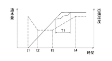
これを具体的に説明する。まず図4は、給湯開始時の通水量の絞り制御と出湯温度の変化とを示すグラフで、点線が通水量、実線が出湯温度である。ここでの絞り制御は、t1で点火を開始すると、規定水量からt2まで通水量を絞り、t3まで絞った通水量を維持した後、徐々に絞りを解除してt4で規定水量に戻す制御となっている。従って、この絞り制御によって出湯温度が二点鎖線で示すように直線的に上昇して設定温度で安定するのが理想である。
一方、図5は、バーナが三段(3ユニット)ある場合の切替制御を示すもので、同図(A)に示すように、給湯開始時(t1)では、二段目のバーナが中間インプットで使用され、通水量の絞りに伴って実線矢印で示すように下限インプットまで絞られた後、点線矢印で示すように一段目の下限インプットへ切り替わり、そこからガスインプットを増加させて火移りさせた後、さらに通水量の絞りに伴って実線矢印で示すようにインプットを絞る。なお、図5の例では、通水量の下限時(t2−t3間)では、実線矢印中の黒点で示すポイントでインプットが維持されている。
This will be described in detail. First, FIG. 4 is a graph showing throttle control of the amount of water flowing at the start of hot water supply and a change in the temperature of the hot water, and the dotted line is the amount of water flowing and the solid line is the temperature of the hot water. The throttle control here is a control in which when ignition is started at t1, the amount of water flow is reduced from the specified amount to t2, the amount of water flow is maintained at t3, and then the throttle is gradually released to return to the specified amount at t4. It has become. Therefore, it is ideal that the hot water temperature rises linearly as shown by the alternate long and short dash line and stabilizes at the set temperature by this throttle control.
On the other hand, FIG. 5 shows switching control when there are three stages (3 units) of burners, and as shown in FIG. 5A, at the start of hot water supply (t1), the second stage burner is an intermediate input. After being narrowed down to the lower limit input as shown by the solid arrow as the water flow is reduced, it was switched to the lower limit input of the first stage as shown by the dotted arrow, and the gas input was increased from there to transfer the fire. After that, the input is further reduced as shown by the solid arrow as the amount of water flow is reduced. In the example of FIG. 5, at the lower limit of the water flow amount (between t2-t3), the input is maintained at the point indicated by the black dot in the solid line arrow.
そして、同図(B)に示すように、t3から通水量の絞りを解除する際には、実線矢印で示すように一段目の上限インプットまで増加させた後、点線矢印で示すように中間インプットまで絞り、二段目の中間インプットからやや絞った状態で火移りを行う。次に、実線矢印で示すように二段目の上限インプットまで増加させた後、点線矢印で示すように中間インプットまで絞り、三段目の中間インプットからやや絞った状態で火移りを行い、実線矢印で示すようにt4までインプットを増加させることになる。
このように、通水量の絞りを解除するt3−t4の間に2度の燃焼段の切替を行うことで、図4に示すように、出湯温度が二点鎖線のように直線的に上昇せず、T1部分でふらついてアンダーシュートが発生してしまうのである。
Then, as shown in the figure (B), when releasing the throttle of the water flow rate from t3, the input is increased to the upper limit input of the first stage as shown by the solid line arrow, and then the intermediate input is shown by the dotted line arrow. Squeeze to, and transfer the fire with the middle input of the second stage slightly squeezed. Next, after increasing to the upper limit input of the second stage as shown by the solid line arrow, narrow down to the intermediate input as shown by the dotted line arrow, and perform fire transfer in a state where it is slightly narrowed down from the middle input of the third stage, and solid line. The input will be increased up to t4 as indicated by the arrow.
In this way, by switching the combustion stage twice between t3-t4, which releases the throttle of water flow, the hot water temperature rises linearly as shown by the alternate long and short dash line, as shown in FIG. Instead, it staggers at the T1 part and undershoot occurs.
そこで、本発明は、給湯開始時に通水量を絞る制御を行うものにおいて、通水量の絞りを解除する際にアンダーシュートが発生せず、安定した出湯温制御を行うことができる給湯器を提供することを目的としたものである。 Therefore, the present invention provides a water heater that controls to throttle the amount of water flow at the start of hot water supply, and can perform stable hot water temperature control without undershoot when the throttle of the amount of water flow is released. The purpose is to do that.
上記目的を達成するために、請求項1に記載の発明は、複数段のバーナと、給水管と出湯管とが接続されてバーナに加熱される熱交換器と、給水管に設けられて熱交換器の通水量を制御する通水量制御手段と、出湯管内の湯温を検出する温度検出手段と、バーナの燃焼段の切替制御及び通水量制御手段の動作制御により、温度検出手段から得られる検出温度を設定温度に一致させる出湯温制御を実行する運転制御手段とを備えた給湯器であって、
運転制御手段は、給湯開始時に所定の通水絞り開始条件の成立を確認すると、予め規定される規定水量よりも小さく、且つバーナの燃焼段の切替が起こらない若しくは最小回数となる目標流量を算出し、通水量制御手段を目標流量として出湯温制御を行い、所定の通水絞り解除条件の成立を確認すると、通水量の絞りを徐々に解除して規定水量へ戻す通水制御を実行することを特徴とする。
請求項2に記載の発明は、請求項1の構成において、通水絞り開始条件は、検出温度を設定温度と比較し、検出温度が設定温度よりも所定温度以上低い場合であることを特徴とする。
請求項3に記載の発明は、請求項1又は2の構成において、通水絞り解除条件は、検出温度と設定温度との差が所定温度以内の場合であることを特徴とする。
In order to achieve the above object, the invention according to
When the operation control means confirms that the predetermined water flow throttle start condition is satisfied at the start of hot water supply, the operation control means calculates a target flow rate that is smaller than the predetermined water volume and does not cause switching of the combustion stage of the burner or is the minimum number of times. Then, the hot water temperature is controlled using the water flow control means as the target flow rate, and when it is confirmed that the predetermined water flow throttle release condition is satisfied, the water flow control is executed to gradually release the water flow rate throttle and return it to the specified water flow rate. It is characterized by.
The invention according to
The invention according to claim 3 is characterized in that, in the configuration of
請求項1に記載の発明によれば、運転制御手段は、給湯開始時に所定の通水絞り開始条件の成立を確認すると、予め規定される規定水量よりも小さく、且つバーナの燃焼段の切替が起こらない若しくは最小回数となる目標流量を算出し、通水量制御手段を目標流量として通水量制御を行っているので、通水量の絞りを解除する際のアンダーシュートを抑制することができる。
請求項2に記載の発明によれば、請求項1の効果に加えて、通水絞り開始条件を、検出温度が設定温度よりも所定温度以上低い場合であることとしているので、いわゆるコールドスタートの場合でも設定温度への到達時間を短くして水やガスの節約に繋げることができる。
一方、検出温度が高くなるホットスタートの場合では、通水絞り開始条件を満たさないので、通水絞りが実行されない。このため、使用者の利便性が損なわれるのを防止することができる。
請求項3に記載の発明によれば、請求項1又は2の効果に加えて、通水絞り解除条件を、検出温度と設定温度との差が所定温度以内の場合としているので、適正なタイミングで規定水量に戻すことができる。
According to the invention of
According to the invention of
On the other hand, in the case of hot start in which the detection temperature becomes high, the water flow throttle start condition is not satisfied, so that the water flow throttle is not executed. Therefore, it is possible to prevent the convenience of the user from being impaired.
According to the invention of claim 3, in addition to the effect of
以下、本発明の実施の形態を図面に基づいて説明する。
図1は、給湯器の一例を示す概略図で、給湯器1は、器具本体内に、給気ファン3を備えた燃焼室2を形成して、燃焼室2の内部に、燃料ガスと給気ファン3からの一次空気との混合ガスを燃焼させる複数(ここではそれぞれ燃焼能力が異なる3ユニット)のバーナ4,4・・を備えると共に、バーナ4の燃焼によって加熱され、給水管6と出湯管7とを接続した熱交換器5を設けている。バーナ4へのガス管8には、元電磁弁9及びガス比例弁10が設けられ、ガス管8から分岐する各バーナ4への分岐管には、切替電磁弁11,11・・がそれぞれ設けられて、各弁が運転制御手段としてのコントローラ12によって制御可能となっている。13はイグナイタ、14は点火電極、15はフレームロッドである。
Hereinafter, embodiments of the present invention will be described with reference to the drawings.
FIG. 1 is a schematic view showing an example of a water heater. The
また、給水管6と出湯管7との間には、熱交換器5をバイパスするバイパス管16が接続されて、給水管6におけるバイパス管16との接続位置よりも上流側には、器具全体に流れる水量を検出する水量センサ17と、通水量制御手段となる水量サーボ18とが設けられ、バイパス管16との接続位置には、バイパス管16への水量を制御するバイパスサーボ19が設けられて、それぞれコントローラ12に電気的に接続されている。一方、出湯管7は、給湯栓20に接続されると共に、バイパス管16の接続部分より下流側と上流側(熱交換器5からの出口際)との湯の温度をそれぞれ検出するサーミスタ21,22が設けられて、コントローラ12に電気的に接続されている。23は設定温度等を設定操作可能なリモコンである。
Further, a
以上の如く構成された給湯器1の動作を、図2のフローチャートに基づいて説明する。
まず、給湯栓20を開いて器具内に通水させ、S1で通水検知(水量センサ17から得られる信号によって器具内を流れる通水量が点火水量を超えていることが確認)されると、コントローラ12は、S2で、点火動作を開始する。すなわち、給気ファン3を回転させてプリパージを行い、元電磁弁9と切替電磁弁11及びガス比例弁10をそれぞれ開いてバーナ4にガスを供給すると共に、イグナイタ13を作動させてバーナ4の点火制御を行う。バーナ4の点火はフレームロッド15で確認される。
The operation of the
First, the
次に、S3で、コントローラ12は、通水絞り動作が必要か否かを判別する。これは、予め設定された通水絞り開始条件(ここでは温度検出手段としてのサーミスタ21から得られる出湯温度と、リモコンで設定される設定温度との差が例えば10℃を超えているような場合)が成立している場合に、通水絞り動作が必要と判断される。ここで通水絞り動作が不要と判断されれば、S8へ移る。
S3で通水絞り動作が必要と判断されると、S4で、予め設定された規定水量よりも小さく、且つバーナ4の燃焼段の切替が最小回数となる目標流量αを算出する。この目標流量αは、現在燃焼中のバーナ4の燃焼段で与えられる最大熱量と入水温度、設定温度とから予め設定された計算式に基づいて算出される。
目標流量αが算出されたら、S5で、コントローラ12は、水量サーボ18を算出された目標流量αとすると共に、温度検出手段としてのサーミスタ21で検出された出湯温度(検出温度)と、リモコン23で設定された設定温度との差に応じて、ガス比例弁10の開度を制御してガス量を連続的に変化させ、出湯温度を設定温度に一致させるための出湯温制御を行う。
Next, in S3, the
When it is determined in S3 that the water flow throttle operation is necessary, the target flow rate α is calculated in S4, which is smaller than the preset specified amount of water and the number of times the combustion stage of the
After the target flow rate α is calculated, in S5, the
その後、S6で、通水絞り解除条件が成立したか否かを判別する。ここでは、出湯温度と設定温度との差が例えば±3℃以内である場合に成立となる。
通水絞り解除条件が成立すれば、S7で通水絞りを解除して水量サーボ18を規定水量まで徐々に戻す制御を行う。
そして、S8で給湯栓20の閉栓によって通水が検知されなくなると、コントローラ12は、S9で元電磁弁9、切替電磁弁11、ガス比例弁10を夫々閉弁させてバーナ4を消火させ、給気ファン3を一定時間回転させてポストパージを行う消火動作を実行する。
After that, in S6, it is determined whether or not the water flow throttle release condition is satisfied. Here, it is established when the difference between the hot water temperature and the set temperature is, for example, within ± 3 ° C.
When the water flow throttle release condition is satisfied, the water flow throttle is released in S7 and the
Then, when water flow is no longer detected by closing the hot
図3(A)は、図4と同様に上記形態における給湯開始時の通水量の絞り制御と出湯温度の変化とを示すグラフ、同図(B)(C)は、バーナ4の燃焼段の切替制御を示すグラフで、(B)は通水絞り時、(C)は通水絞り解除時をそれぞれ示す。
ここで明らかなように、t2での通水絞りが目標流量αに設定されていることから、通水絞り時では、バーナ4も二段のままt2までガスインプットを最小値とする制御にとどまり、燃焼段の切替が行われず、t3−t4の通水絞り解除時では、バーナ4の燃焼段の切替が1度だけとなっている。
よって、図5のように燃焼段の切替が2度行われる場合と比較して、上昇中の出湯温度のふらつきが緩和され(図3(A)のT1部分)、出湯温度が図4よりも略直線的に変化してアンダーシュートの発生が抑制されていることがわかる。
FIG. 3A is a graph showing the throttle control of the amount of water flowing at the start of hot water supply and the change in the hot water outlet temperature in the same manner as in FIG. 4, and FIGS. 3B and 4C are the combustion stages of the
As is clear here, since the water flow throttle at t2 is set to the target flow rate α, at the time of the water flow throttle, the
Therefore, as compared with the case where the combustion stage is switched twice as shown in FIG. 5, the fluctuation of the hot water temperature during the rise is alleviated (T1 portion in FIG. 3 (A)), and the hot water temperature is higher than that in FIG. It can be seen that the temperature changes substantially linearly and the occurrence of undershoot is suppressed.
このように、上記形態の給湯器1によれば、コントローラ12は、給湯開始時に所定の通水絞り開始条件の成立を確認すると、予め規定される規定水量よりも小さく、且つバーナ4の燃焼段の切替が最小回数となる目標流量αを算出し、水量サーボ18を目標流量αとして通水量制御を行い、所定の通水絞り解除条件の成立を確認すると、通水量の絞りを徐々に解除して規定水量へ戻す通水制御を実行することで、通水量の絞りを解除する際のアンダーシュートを抑制することができる。
As described above, according to the
特にここでは、通水絞り開始条件を、出湯温度を設定温度と比較し、出湯温度が設定温度よりも10℃以上低い場合であることとしているので、いわゆるコールドスタートの場合でも設定温度への到達時間を短くして水やガスの節約に繋げることができる。
一方、検出温度が高くなるホットスタートの場合では、通水絞り開始条件を満たさないので、通水絞りが実行されない。このため、使用者の利便性が損なわれるのを防止することができる。
さらに、通水絞り解除条件を、出湯温度と設定温度との差が±3℃以内の場合としているので、適正なタイミングで規定水量に戻すことができる。
In particular, here, the condition for starting the water flow squeezing is that the hot water temperature is compared with the set temperature and the hot water temperature is 10 ° C or more lower than the set temperature. Therefore, the set temperature is reached even in the case of so-called cold start. You can save time and save water and gas.
On the other hand, in the case of hot start in which the detection temperature becomes high, the water flow throttle start condition is not satisfied, so that the water flow throttle is not executed. Therefore, it is possible to prevent the convenience of the user from being impaired.
Further, since the water flow squeezing release condition is set when the difference between the hot water discharge temperature and the set temperature is within ± 3 ° C., the specified amount of water can be returned at an appropriate timing.
なお、上記形態では、バーナの燃焼段の切替が1回(最小回数)となる目標流量を算出しているが、燃焼段の切替回数が少なくなるような目標流量を算出してもよく、また、燃焼段の切替が起こらない目標流量を算出してもよい。
また、通水絞り開始条件を、出湯温度と設定温度との差が10℃を超えている場合としているが、この差は10℃以外でも設定可能である。また、この条件に限らず、前回の運転終了から5分以上経過している場合としてもよい。さらに、電源投入後の初回運転の場合にも必要と判断するようにしてもよいし、これらの条件が複数揃った場合としてもよい。同様に、通水絞り解除条件も、出湯温度と設定温度との差が±3℃以内の場合とするに限らず、差は適宜変更できるし、他の条件も設定できる。
In the above embodiment, the target flow rate at which the combustion stage of the burner is switched once (minimum number of times) is calculated, but the target flow rate may be calculated so that the number of times of switching the combustion stage is reduced. , The target flow rate at which the switching of the combustion stage does not occur may be calculated.
Further, the water flow squeezing start condition is set when the difference between the hot water discharge temperature and the set temperature exceeds 10 ° C., but this difference can be set other than 10 ° C. Further, the condition is not limited to this, and it may be a case where 5 minutes or more have passed since the end of the previous operation. Further, it may be determined that it is necessary even in the case of the first operation after the power is turned on, or it may be the case where a plurality of these conditions are satisfied. Similarly, the water flow squeezing release condition is not limited to the case where the difference between the hot water outlet temperature and the set temperature is within ± 3 ° C., the difference can be changed as appropriate, and other conditions can be set.
その他、給湯器自体の形態も上記内容に限らず、バーナの段数の増減は勿論、バイパス管を有しないタイプ、風呂用熱交換器を備えて浴槽への湯張りや追い炊きが可能な風呂側回路を併設したタイプ、潜熱回収用の熱交換器を併設したタイプ等、水量サーボ等の通水量制御手段を備えた給湯器であれば本発明の適用は可能である。 In addition, the form of the water heater itself is not limited to the above, and the number of stages of the burner can be increased or decreased, as well as a type that does not have a bypass pipe, and a bath side that is equipped with a heat exchanger for the bath and can be filled with hot water or re-cooked. The present invention can be applied to a water heater equipped with a water flow control means such as a water volume servo, such as a type having a circuit and a heat exchanger for recovering latent heat.
1・・給湯器、2・・燃焼室、3・・給気ファン、4・・バーナ、5・・熱交換器、6・・給水管、7・・出湯管、10・・ガス比例弁、12・・コントローラ、18・・水量サーボ、20・・給湯栓、21,22・・サーミスタ、23・・リモコン。 1 ... Water heater, 2 ... Combustion chamber, 3 ... Air supply fan, 4 ... Burner, 5 ... Heat exchanger, 6 ... Water supply pipe, 7 ... Hot water supply pipe, 10 ... Gas proportional valve, 12 ... Controller, 18 ... Water volume servo, 20 ... Hot water tap, 21,22 ... Thermista, 23 ... Remote control.
Claims (3)
給水管と出湯管とが接続されて前記バーナに加熱される熱交換器と、
前記給水管に設けられて前記熱交換器の通水量を制御する通水量制御手段と、
前記出湯管内の湯温を検出する温度検出手段と、
前記バーナの燃焼段の切替制御及び前記通水量制御手段の動作制御により、前記温度検出手段から得られる検出温度を設定温度に一致させる出湯温制御を実行する運転制御手段とを備えた給湯器であって、
前記運転制御手段は、給湯開始時に所定の通水絞り開始条件の成立を確認すると、予め規定される規定水量よりも小さく、且つ前記バーナの燃焼段の切替が起こらない若しくは最小回数となる目標流量を算出し、前記通水量制御手段を前記目標流量として前記出湯温制御を行い、所定の通水絞り解除条件の成立を確認すると、前記通水量の絞りを徐々に解除して前記規定水量へ戻す通水制御を実行することを特徴とする給湯器。 With a multi-stage burner,
A heat exchanger in which the water supply pipe and the hot water pipe are connected and heated to the burner,
A water flow control means provided in the water supply pipe to control the water flow rate of the heat exchanger, and
A temperature detecting means for detecting the temperature of hot water in the hot water pipe, and
A water heater provided with an operation control means for executing a hot water discharge temperature control for matching a detection temperature obtained from the temperature detection means with a set temperature by switching a combustion stage of the burner and controlling an operation of the water flow amount control means. There,
When the operation control means confirms that the predetermined water flow throttle start condition is satisfied at the start of hot water supply, the target flow rate is smaller than the predetermined water amount and the combustion stage of the burner does not switch or becomes the minimum number of times. Is calculated, the hot water temperature is controlled using the water flow rate control means as the target flow rate, and when it is confirmed that the predetermined water flow throttle release condition is satisfied, the water flow rate throttle is gradually released and returned to the specified water flow rate. A water heater characterized by performing water flow control.
Priority Applications (3)
| Application Number | Priority Date | Filing Date | Title |
|---|---|---|---|
| JP2017103868A JP6952985B2 (en) | 2017-05-25 | 2017-05-25 | Water heater |
| US15/942,727 US10619889B2 (en) | 2017-05-25 | 2018-04-02 | Water heater |
| AU2018202419A AU2018202419B2 (en) | 2017-05-25 | 2018-04-05 | Water heater |
Applications Claiming Priority (1)
| Application Number | Priority Date | Filing Date | Title |
|---|---|---|---|
| JP2017103868A JP6952985B2 (en) | 2017-05-25 | 2017-05-25 | Water heater |
Publications (2)
| Publication Number | Publication Date |
|---|---|
| JP2018200124A JP2018200124A (en) | 2018-12-20 |
| JP6952985B2 true JP6952985B2 (en) | 2021-10-27 |
Family
ID=64400407
Family Applications (1)
| Application Number | Title | Priority Date | Filing Date |
|---|---|---|---|
| JP2017103868A Active JP6952985B2 (en) | 2017-05-25 | 2017-05-25 | Water heater |
Country Status (3)
| Country | Link |
|---|---|
| US (1) | US10619889B2 (en) |
| JP (1) | JP6952985B2 (en) |
| AU (1) | AU2018202419B2 (en) |
Families Citing this family (8)
| Publication number | Priority date | Publication date | Assignee | Title |
|---|---|---|---|---|
| CN109631316A (en) * | 2018-12-29 | 2019-04-16 | 北京理工大学 | A kind of gas heater and its control method |
| CN110513863A (en) * | 2019-08-20 | 2019-11-29 | 华帝股份有限公司 | Gas water heater capable of being connected in series, series system, pressurization method and preheating method |
| CN110513862B (en) * | 2019-08-20 | 2024-04-12 | 华帝股份有限公司 | Series-type gas water heater, series-type system, pressurizing method and preheating method |
| CN112833555B (en) * | 2020-06-15 | 2022-08-16 | 青岛经济技术开发区海尔热水器有限公司 | Gas water heater and control method thereof |
| CN111664571A (en) * | 2020-06-19 | 2020-09-15 | 海信(广东)厨卫系统有限公司 | Gas water heater and control method thereof |
| CN112484310B (en) * | 2020-11-12 | 2022-04-26 | 华帝股份有限公司 | Control method of electric water regulating valve of gas water heater |
| CN112682944B (en) * | 2020-12-14 | 2022-12-23 | 威能(无锡)供热设备有限公司 | Burner assembly and gas water heating equipment comprising same |
| CN114440469B (en) * | 2022-02-09 | 2023-03-28 | 宁波方太厨具有限公司 | Anti-freezing control method and system for water heater, gas water heater and medium |
Family Cites Families (7)
| Publication number | Priority date | Publication date | Assignee | Title |
|---|---|---|---|---|
| US4501261A (en) * | 1982-06-28 | 1985-02-26 | Toto Limited | Instantaneous gas water heater |
| KR910000677B1 (en) * | 1985-07-15 | 1991-01-31 | 도오도오 기기 가부시기가이샤 | Multiple-purpose instantaneous gas water heater |
| KR930000669B1 (en) * | 1988-09-06 | 1993-01-29 | 마쯔시다덴기산교 가부시기가이샤 | Automatic hot water supply apparatus |
| JP4562251B2 (en) * | 2000-07-13 | 2010-10-13 | 株式会社丸山製作所 | Water softener |
| JP4234738B2 (en) * | 2006-07-26 | 2009-03-04 | リンナイ株式会社 | Linked hot water system |
| JP4620017B2 (en) | 2006-08-31 | 2011-01-26 | リンナイ株式会社 | Water heater |
| JP5312910B2 (en) | 2008-11-11 | 2013-10-09 | 株式会社パロマ | Water heater |
-
2017
- 2017-05-25 JP JP2017103868A patent/JP6952985B2/en active Active
-
2018
- 2018-04-02 US US15/942,727 patent/US10619889B2/en active Active
- 2018-04-05 AU AU2018202419A patent/AU2018202419B2/en active Active
Also Published As
| Publication number | Publication date |
|---|---|
| US20180340710A1 (en) | 2018-11-29 |
| JP2018200124A (en) | 2018-12-20 |
| AU2018202419B2 (en) | 2023-03-23 |
| AU2018202419A1 (en) | 2018-12-13 |
| US10619889B2 (en) | 2020-04-14 |
Similar Documents
| Publication | Publication Date | Title |
|---|---|---|
| JP6952985B2 (en) | Water heater | |
| JP5312910B2 (en) | Water heater | |
| JP5154370B2 (en) | Water heater | |
| JP4350698B2 (en) | Connected water heater | |
| JP2018100810A (en) | Combustion apparatus | |
| JP6867684B2 (en) | Water heater | |
| US11313589B2 (en) | Tankless water heater with bypass valve operating differently in intermittent operation and normal operation | |
| JP6667365B2 (en) | Water heater | |
| JP3533799B2 (en) | Water heater | |
| JP2008128575A (en) | Combustion apparatus | |
| JP5454914B2 (en) | Water heater | |
| JP6709676B2 (en) | Water heater | |
| JP6650761B2 (en) | Water heater | |
| JP5200748B2 (en) | Water heater | |
| JP6057125B2 (en) | Combustion device | |
| JP5872963B2 (en) | Water heater | |
| JP5970529B2 (en) | Water heater | |
| JP6735572B2 (en) | Water heater | |
| JP2022142541A (en) | Water heater | |
| JP2018204862A (en) | Bath water heater | |
| JP2019066126A (en) | Bath water heater | |
| JP2018119749A (en) | Water heater | |
| JPH09273810A (en) | Measuring method of residual hot-water volume in bathtub of bath boiler unit with hot-water supply function | |
| JP2003247751A (en) | Control method of hot water supplier | |
| JP2019015426A (en) | Water heater |
Legal Events
| Date | Code | Title | Description |
|---|---|---|---|
| A621 | Written request for application examination |
Free format text: JAPANESE INTERMEDIATE CODE: A621 Effective date: 20200514 |
|
| A977 | Report on retrieval |
Free format text: JAPANESE INTERMEDIATE CODE: A971007 Effective date: 20210309 |
|
| A131 | Notification of reasons for refusal |
Free format text: JAPANESE INTERMEDIATE CODE: A131 Effective date: 20210316 |
|
| TRDD | Decision of grant or rejection written | ||
| A01 | Written decision to grant a patent or to grant a registration (utility model) |
Free format text: JAPANESE INTERMEDIATE CODE: A01 Effective date: 20210907 |
|
| A61 | First payment of annual fees (during grant procedure) |
Free format text: JAPANESE INTERMEDIATE CODE: A61 Effective date: 20210921 |
|
| R150 | Certificate of patent or registration of utility model |
Ref document number: 6952985 Country of ref document: JP Free format text: JAPANESE INTERMEDIATE CODE: R150 |