JP6950835B2 - Manufacturing method of high-strength member, high-strength member and steel plate for high-strength member - Google Patents
Manufacturing method of high-strength member, high-strength member and steel plate for high-strength member Download PDFInfo
- Publication number
- JP6950835B2 JP6950835B2 JP2020545826A JP2020545826A JP6950835B2 JP 6950835 B2 JP6950835 B2 JP 6950835B2 JP 2020545826 A JP2020545826 A JP 2020545826A JP 2020545826 A JP2020545826 A JP 2020545826A JP 6950835 B2 JP6950835 B2 JP 6950835B2
- Authority
- JP
- Japan
- Prior art keywords
- less
- steel sheet
- face
- strength member
- strength
- Prior art date
- Legal status (The legal status is an assumption and is not a legal conclusion. Google has not performed a legal analysis and makes no representation as to the accuracy of the status listed.)
- Active
Links
Images


Classifications
-
- C—CHEMISTRY; METALLURGY
- C21—METALLURGY OF IRON
- C21D—MODIFYING THE PHYSICAL STRUCTURE OF FERROUS METALS; GENERAL DEVICES FOR HEAT TREATMENT OF FERROUS OR NON-FERROUS METALS OR ALLOYS; MAKING METAL MALLEABLE, e.g. BY DECARBURISATION OR TEMPERING
- C21D9/00—Heat treatment, e.g. annealing, hardening, quenching or tempering, adapted for particular articles; Furnaces therefor
- C21D9/46—Heat treatment, e.g. annealing, hardening, quenching or tempering, adapted for particular articles; Furnaces therefor for sheet metals
-
- C—CHEMISTRY; METALLURGY
- C21—METALLURGY OF IRON
- C21D—MODIFYING THE PHYSICAL STRUCTURE OF FERROUS METALS; GENERAL DEVICES FOR HEAT TREATMENT OF FERROUS OR NON-FERROUS METALS OR ALLOYS; MAKING METAL MALLEABLE, e.g. BY DECARBURISATION OR TEMPERING
- C21D1/00—General methods or devices for heat treatment, e.g. annealing, hardening, quenching or tempering
- C21D1/18—Hardening; Quenching with or without subsequent tempering
- C21D1/19—Hardening; Quenching with or without subsequent tempering by interrupted quenching
- C21D1/22—Martempering
-
- B—PERFORMING OPERATIONS; TRANSPORTING
- B21—MECHANICAL METAL-WORKING WITHOUT ESSENTIALLY REMOVING MATERIAL; PUNCHING METAL
- B21B—ROLLING OF METAL
- B21B1/00—Metal-rolling methods or mills for making semi-finished products of solid or profiled cross-section; Sequence of operations in milling trains; Layout of rolling-mill plant, e.g. grouping of stands; Succession of passes or of sectional pass alternations
- B21B1/38—Metal-rolling methods or mills for making semi-finished products of solid or profiled cross-section; Sequence of operations in milling trains; Layout of rolling-mill plant, e.g. grouping of stands; Succession of passes or of sectional pass alternations for rolling sheets of limited length, e.g. folded sheets, superimposed sheets, pack rolling
-
- B—PERFORMING OPERATIONS; TRANSPORTING
- B21—MECHANICAL METAL-WORKING WITHOUT ESSENTIALLY REMOVING MATERIAL; PUNCHING METAL
- B21C—MANUFACTURE OF METAL SHEETS, WIRE, RODS, TUBES OR PROFILES, OTHERWISE THAN BY ROLLING; AUXILIARY OPERATIONS USED IN CONNECTION WITH METAL-WORKING WITHOUT ESSENTIALLY REMOVING MATERIAL
- B21C37/00—Manufacture of metal sheets, bars, wire, tubes or like semi-manufactured products, not otherwise provided for; Manufacture of tubes of special shape
- B21C37/02—Manufacture of metal sheets, bars, wire, tubes or like semi-manufactured products, not otherwise provided for; Manufacture of tubes of special shape of sheets
-
- B—PERFORMING OPERATIONS; TRANSPORTING
- B21—MECHANICAL METAL-WORKING WITHOUT ESSENTIALLY REMOVING MATERIAL; PUNCHING METAL
- B21D—WORKING OR PROCESSING OF SHEET METAL OR METAL TUBES, RODS OR PROFILES WITHOUT ESSENTIALLY REMOVING MATERIAL; PUNCHING METAL
- B21D5/00—Bending sheet metal along straight lines, e.g. to form simple curves
-
- C—CHEMISTRY; METALLURGY
- C21—METALLURGY OF IRON
- C21D—MODIFYING THE PHYSICAL STRUCTURE OF FERROUS METALS; GENERAL DEVICES FOR HEAT TREATMENT OF FERROUS OR NON-FERROUS METALS OR ALLOYS; MAKING METAL MALLEABLE, e.g. BY DECARBURISATION OR TEMPERING
- C21D1/00—General methods or devices for heat treatment, e.g. annealing, hardening, quenching or tempering
- C21D1/26—Methods of annealing
-
- C—CHEMISTRY; METALLURGY
- C21—METALLURGY OF IRON
- C21D—MODIFYING THE PHYSICAL STRUCTURE OF FERROUS METALS; GENERAL DEVICES FOR HEAT TREATMENT OF FERROUS OR NON-FERROUS METALS OR ALLOYS; MAKING METAL MALLEABLE, e.g. BY DECARBURISATION OR TEMPERING
- C21D6/00—Heat treatment of ferrous alloys
- C21D6/001—Heat treatment of ferrous alloys containing Ni
-
- C—CHEMISTRY; METALLURGY
- C21—METALLURGY OF IRON
- C21D—MODIFYING THE PHYSICAL STRUCTURE OF FERROUS METALS; GENERAL DEVICES FOR HEAT TREATMENT OF FERROUS OR NON-FERROUS METALS OR ALLOYS; MAKING METAL MALLEABLE, e.g. BY DECARBURISATION OR TEMPERING
- C21D6/00—Heat treatment of ferrous alloys
- C21D6/002—Heat treatment of ferrous alloys containing Cr
-
- C—CHEMISTRY; METALLURGY
- C21—METALLURGY OF IRON
- C21D—MODIFYING THE PHYSICAL STRUCTURE OF FERROUS METALS; GENERAL DEVICES FOR HEAT TREATMENT OF FERROUS OR NON-FERROUS METALS OR ALLOYS; MAKING METAL MALLEABLE, e.g. BY DECARBURISATION OR TEMPERING
- C21D6/00—Heat treatment of ferrous alloys
- C21D6/005—Heat treatment of ferrous alloys containing Mn
-
- C—CHEMISTRY; METALLURGY
- C21—METALLURGY OF IRON
- C21D—MODIFYING THE PHYSICAL STRUCTURE OF FERROUS METALS; GENERAL DEVICES FOR HEAT TREATMENT OF FERROUS OR NON-FERROUS METALS OR ALLOYS; MAKING METAL MALLEABLE, e.g. BY DECARBURISATION OR TEMPERING
- C21D6/00—Heat treatment of ferrous alloys
- C21D6/008—Heat treatment of ferrous alloys containing Si
-
- C—CHEMISTRY; METALLURGY
- C21—METALLURGY OF IRON
- C21D—MODIFYING THE PHYSICAL STRUCTURE OF FERROUS METALS; GENERAL DEVICES FOR HEAT TREATMENT OF FERROUS OR NON-FERROUS METALS OR ALLOYS; MAKING METAL MALLEABLE, e.g. BY DECARBURISATION OR TEMPERING
- C21D8/00—Modifying the physical properties by deformation combined with, or followed by, heat treatment
- C21D8/02—Modifying the physical properties by deformation combined with, or followed by, heat treatment during manufacturing of plates or strips
- C21D8/0205—Modifying the physical properties by deformation combined with, or followed by, heat treatment during manufacturing of plates or strips of ferrous alloys
-
- C—CHEMISTRY; METALLURGY
- C21—METALLURGY OF IRON
- C21D—MODIFYING THE PHYSICAL STRUCTURE OF FERROUS METALS; GENERAL DEVICES FOR HEAT TREATMENT OF FERROUS OR NON-FERROUS METALS OR ALLOYS; MAKING METAL MALLEABLE, e.g. BY DECARBURISATION OR TEMPERING
- C21D8/00—Modifying the physical properties by deformation combined with, or followed by, heat treatment
- C21D8/02—Modifying the physical properties by deformation combined with, or followed by, heat treatment during manufacturing of plates or strips
- C21D8/0221—Modifying the physical properties by deformation combined with, or followed by, heat treatment during manufacturing of plates or strips characterised by the working steps
- C21D8/0226—Hot rolling
-
- C—CHEMISTRY; METALLURGY
- C21—METALLURGY OF IRON
- C21D—MODIFYING THE PHYSICAL STRUCTURE OF FERROUS METALS; GENERAL DEVICES FOR HEAT TREATMENT OF FERROUS OR NON-FERROUS METALS OR ALLOYS; MAKING METAL MALLEABLE, e.g. BY DECARBURISATION OR TEMPERING
- C21D8/00—Modifying the physical properties by deformation combined with, or followed by, heat treatment
- C21D8/02—Modifying the physical properties by deformation combined with, or followed by, heat treatment during manufacturing of plates or strips
- C21D8/0221—Modifying the physical properties by deformation combined with, or followed by, heat treatment during manufacturing of plates or strips characterised by the working steps
- C21D8/0236—Cold rolling
-
- C—CHEMISTRY; METALLURGY
- C21—METALLURGY OF IRON
- C21D—MODIFYING THE PHYSICAL STRUCTURE OF FERROUS METALS; GENERAL DEVICES FOR HEAT TREATMENT OF FERROUS OR NON-FERROUS METALS OR ALLOYS; MAKING METAL MALLEABLE, e.g. BY DECARBURISATION OR TEMPERING
- C21D8/00—Modifying the physical properties by deformation combined with, or followed by, heat treatment
- C21D8/02—Modifying the physical properties by deformation combined with, or followed by, heat treatment during manufacturing of plates or strips
- C21D8/0247—Modifying the physical properties by deformation combined with, or followed by, heat treatment during manufacturing of plates or strips characterised by the heat treatment
- C21D8/0273—Final recrystallisation annealing
-
- C—CHEMISTRY; METALLURGY
- C21—METALLURGY OF IRON
- C21D—MODIFYING THE PHYSICAL STRUCTURE OF FERROUS METALS; GENERAL DEVICES FOR HEAT TREATMENT OF FERROUS OR NON-FERROUS METALS OR ALLOYS; MAKING METAL MALLEABLE, e.g. BY DECARBURISATION OR TEMPERING
- C21D8/00—Modifying the physical properties by deformation combined with, or followed by, heat treatment
- C21D8/02—Modifying the physical properties by deformation combined with, or followed by, heat treatment during manufacturing of plates or strips
- C21D8/0294—Modifying the physical properties by deformation combined with, or followed by, heat treatment during manufacturing of plates or strips involving a localised treatment
-
- C—CHEMISTRY; METALLURGY
- C21—METALLURGY OF IRON
- C21D—MODIFYING THE PHYSICAL STRUCTURE OF FERROUS METALS; GENERAL DEVICES FOR HEAT TREATMENT OF FERROUS OR NON-FERROUS METALS OR ALLOYS; MAKING METAL MALLEABLE, e.g. BY DECARBURISATION OR TEMPERING
- C21D8/00—Modifying the physical properties by deformation combined with, or followed by, heat treatment
- C21D8/02—Modifying the physical properties by deformation combined with, or followed by, heat treatment during manufacturing of plates or strips
- C21D8/04—Modifying the physical properties by deformation combined with, or followed by, heat treatment during manufacturing of plates or strips to produce plates or strips for deep-drawing
- C21D8/0421—Modifying the physical properties by deformation combined with, or followed by, heat treatment during manufacturing of plates or strips to produce plates or strips for deep-drawing characterised by the working steps
- C21D8/0426—Hot rolling
-
- C—CHEMISTRY; METALLURGY
- C21—METALLURGY OF IRON
- C21D—MODIFYING THE PHYSICAL STRUCTURE OF FERROUS METALS; GENERAL DEVICES FOR HEAT TREATMENT OF FERROUS OR NON-FERROUS METALS OR ALLOYS; MAKING METAL MALLEABLE, e.g. BY DECARBURISATION OR TEMPERING
- C21D8/00—Modifying the physical properties by deformation combined with, or followed by, heat treatment
- C21D8/02—Modifying the physical properties by deformation combined with, or followed by, heat treatment during manufacturing of plates or strips
- C21D8/04—Modifying the physical properties by deformation combined with, or followed by, heat treatment during manufacturing of plates or strips to produce plates or strips for deep-drawing
- C21D8/0421—Modifying the physical properties by deformation combined with, or followed by, heat treatment during manufacturing of plates or strips to produce plates or strips for deep-drawing characterised by the working steps
- C21D8/0436—Cold rolling
-
- C—CHEMISTRY; METALLURGY
- C21—METALLURGY OF IRON
- C21D—MODIFYING THE PHYSICAL STRUCTURE OF FERROUS METALS; GENERAL DEVICES FOR HEAT TREATMENT OF FERROUS OR NON-FERROUS METALS OR ALLOYS; MAKING METAL MALLEABLE, e.g. BY DECARBURISATION OR TEMPERING
- C21D8/00—Modifying the physical properties by deformation combined with, or followed by, heat treatment
- C21D8/02—Modifying the physical properties by deformation combined with, or followed by, heat treatment during manufacturing of plates or strips
- C21D8/04—Modifying the physical properties by deformation combined with, or followed by, heat treatment during manufacturing of plates or strips to produce plates or strips for deep-drawing
- C21D8/0447—Modifying the physical properties by deformation combined with, or followed by, heat treatment during manufacturing of plates or strips to produce plates or strips for deep-drawing characterised by the heat treatment
- C21D8/0473—Final recrystallisation annealing
-
- C—CHEMISTRY; METALLURGY
- C21—METALLURGY OF IRON
- C21D—MODIFYING THE PHYSICAL STRUCTURE OF FERROUS METALS; GENERAL DEVICES FOR HEAT TREATMENT OF FERROUS OR NON-FERROUS METALS OR ALLOYS; MAKING METAL MALLEABLE, e.g. BY DECARBURISATION OR TEMPERING
- C21D8/00—Modifying the physical properties by deformation combined with, or followed by, heat treatment
- C21D8/02—Modifying the physical properties by deformation combined with, or followed by, heat treatment during manufacturing of plates or strips
- C21D8/04—Modifying the physical properties by deformation combined with, or followed by, heat treatment during manufacturing of plates or strips to produce plates or strips for deep-drawing
- C21D8/0494—Modifying the physical properties by deformation combined with, or followed by, heat treatment during manufacturing of plates or strips to produce plates or strips for deep-drawing involving a localised treatment
-
- C—CHEMISTRY; METALLURGY
- C22—METALLURGY; FERROUS OR NON-FERROUS ALLOYS; TREATMENT OF ALLOYS OR NON-FERROUS METALS
- C22C—ALLOYS
- C22C38/00—Ferrous alloys, e.g. steel alloys
-
- C—CHEMISTRY; METALLURGY
- C22—METALLURGY; FERROUS OR NON-FERROUS ALLOYS; TREATMENT OF ALLOYS OR NON-FERROUS METALS
- C22C—ALLOYS
- C22C38/00—Ferrous alloys, e.g. steel alloys
- C22C38/001—Ferrous alloys, e.g. steel alloys containing N
-
- C—CHEMISTRY; METALLURGY
- C22—METALLURGY; FERROUS OR NON-FERROUS ALLOYS; TREATMENT OF ALLOYS OR NON-FERROUS METALS
- C22C—ALLOYS
- C22C38/00—Ferrous alloys, e.g. steel alloys
- C22C38/002—Ferrous alloys, e.g. steel alloys containing In, Mg, or other elements not provided for in one single group C22C38/001 - C22C38/60
-
- C—CHEMISTRY; METALLURGY
- C22—METALLURGY; FERROUS OR NON-FERROUS ALLOYS; TREATMENT OF ALLOYS OR NON-FERROUS METALS
- C22C—ALLOYS
- C22C38/00—Ferrous alloys, e.g. steel alloys
- C22C38/005—Ferrous alloys, e.g. steel alloys containing rare earths, i.e. Sc, Y, Lanthanides
-
- C—CHEMISTRY; METALLURGY
- C22—METALLURGY; FERROUS OR NON-FERROUS ALLOYS; TREATMENT OF ALLOYS OR NON-FERROUS METALS
- C22C—ALLOYS
- C22C38/00—Ferrous alloys, e.g. steel alloys
- C22C38/02—Ferrous alloys, e.g. steel alloys containing silicon
-
- C—CHEMISTRY; METALLURGY
- C22—METALLURGY; FERROUS OR NON-FERROUS ALLOYS; TREATMENT OF ALLOYS OR NON-FERROUS METALS
- C22C—ALLOYS
- C22C38/00—Ferrous alloys, e.g. steel alloys
- C22C38/04—Ferrous alloys, e.g. steel alloys containing manganese
-
- C—CHEMISTRY; METALLURGY
- C22—METALLURGY; FERROUS OR NON-FERROUS ALLOYS; TREATMENT OF ALLOYS OR NON-FERROUS METALS
- C22C—ALLOYS
- C22C38/00—Ferrous alloys, e.g. steel alloys
- C22C38/06—Ferrous alloys, e.g. steel alloys containing aluminium
-
- C—CHEMISTRY; METALLURGY
- C22—METALLURGY; FERROUS OR NON-FERROUS ALLOYS; TREATMENT OF ALLOYS OR NON-FERROUS METALS
- C22C—ALLOYS
- C22C38/00—Ferrous alloys, e.g. steel alloys
- C22C38/08—Ferrous alloys, e.g. steel alloys containing nickel
-
- C—CHEMISTRY; METALLURGY
- C22—METALLURGY; FERROUS OR NON-FERROUS ALLOYS; TREATMENT OF ALLOYS OR NON-FERROUS METALS
- C22C—ALLOYS
- C22C38/00—Ferrous alloys, e.g. steel alloys
- C22C38/12—Ferrous alloys, e.g. steel alloys containing tungsten, tantalum, molybdenum, vanadium, or niobium
-
- C—CHEMISTRY; METALLURGY
- C22—METALLURGY; FERROUS OR NON-FERROUS ALLOYS; TREATMENT OF ALLOYS OR NON-FERROUS METALS
- C22C—ALLOYS
- C22C38/00—Ferrous alloys, e.g. steel alloys
- C22C38/14—Ferrous alloys, e.g. steel alloys containing titanium or zirconium
-
- C—CHEMISTRY; METALLURGY
- C22—METALLURGY; FERROUS OR NON-FERROUS ALLOYS; TREATMENT OF ALLOYS OR NON-FERROUS METALS
- C22C—ALLOYS
- C22C38/00—Ferrous alloys, e.g. steel alloys
- C22C38/16—Ferrous alloys, e.g. steel alloys containing copper
-
- C—CHEMISTRY; METALLURGY
- C22—METALLURGY; FERROUS OR NON-FERROUS ALLOYS; TREATMENT OF ALLOYS OR NON-FERROUS METALS
- C22C—ALLOYS
- C22C38/00—Ferrous alloys, e.g. steel alloys
- C22C38/18—Ferrous alloys, e.g. steel alloys containing chromium
- C22C38/20—Ferrous alloys, e.g. steel alloys containing chromium with copper
-
- C—CHEMISTRY; METALLURGY
- C22—METALLURGY; FERROUS OR NON-FERROUS ALLOYS; TREATMENT OF ALLOYS OR NON-FERROUS METALS
- C22C—ALLOYS
- C22C38/00—Ferrous alloys, e.g. steel alloys
- C22C38/18—Ferrous alloys, e.g. steel alloys containing chromium
- C22C38/22—Ferrous alloys, e.g. steel alloys containing chromium with molybdenum or tungsten
-
- C—CHEMISTRY; METALLURGY
- C22—METALLURGY; FERROUS OR NON-FERROUS ALLOYS; TREATMENT OF ALLOYS OR NON-FERROUS METALS
- C22C—ALLOYS
- C22C38/00—Ferrous alloys, e.g. steel alloys
- C22C38/18—Ferrous alloys, e.g. steel alloys containing chromium
- C22C38/24—Ferrous alloys, e.g. steel alloys containing chromium with vanadium
-
- C—CHEMISTRY; METALLURGY
- C22—METALLURGY; FERROUS OR NON-FERROUS ALLOYS; TREATMENT OF ALLOYS OR NON-FERROUS METALS
- C22C—ALLOYS
- C22C38/00—Ferrous alloys, e.g. steel alloys
- C22C38/18—Ferrous alloys, e.g. steel alloys containing chromium
- C22C38/26—Ferrous alloys, e.g. steel alloys containing chromium with niobium or tantalum
-
- C—CHEMISTRY; METALLURGY
- C22—METALLURGY; FERROUS OR NON-FERROUS ALLOYS; TREATMENT OF ALLOYS OR NON-FERROUS METALS
- C22C—ALLOYS
- C22C38/00—Ferrous alloys, e.g. steel alloys
- C22C38/18—Ferrous alloys, e.g. steel alloys containing chromium
- C22C38/38—Ferrous alloys, e.g. steel alloys containing chromium with more than 1.5% by weight of manganese
-
- C—CHEMISTRY; METALLURGY
- C22—METALLURGY; FERROUS OR NON-FERROUS ALLOYS; TREATMENT OF ALLOYS OR NON-FERROUS METALS
- C22C—ALLOYS
- C22C38/00—Ferrous alloys, e.g. steel alloys
- C22C38/60—Ferrous alloys, e.g. steel alloys containing lead, selenium, tellurium, or antimony, or more than 0.04% by weight of sulfur
-
- B—PERFORMING OPERATIONS; TRANSPORTING
- B21—MECHANICAL METAL-WORKING WITHOUT ESSENTIALLY REMOVING MATERIAL; PUNCHING METAL
- B21B—ROLLING OF METAL
- B21B1/00—Metal-rolling methods or mills for making semi-finished products of solid or profiled cross-section; Sequence of operations in milling trains; Layout of rolling-mill plant, e.g. grouping of stands; Succession of passes or of sectional pass alternations
- B21B1/38—Metal-rolling methods or mills for making semi-finished products of solid or profiled cross-section; Sequence of operations in milling trains; Layout of rolling-mill plant, e.g. grouping of stands; Succession of passes or of sectional pass alternations for rolling sheets of limited length, e.g. folded sheets, superimposed sheets, pack rolling
- B21B2001/386—Plates
-
- B—PERFORMING OPERATIONS; TRANSPORTING
- B21—MECHANICAL METAL-WORKING WITHOUT ESSENTIALLY REMOVING MATERIAL; PUNCHING METAL
- B21D—WORKING OR PROCESSING OF SHEET METAL OR METAL TUBES, RODS OR PROFILES WITHOUT ESSENTIALLY REMOVING MATERIAL; PUNCHING METAL
- B21D5/00—Bending sheet metal along straight lines, e.g. to form simple curves
- B21D5/008—Bending sheet metal along straight lines, e.g. to form simple curves combined with heating or cooling of the bends
-
- C—CHEMISTRY; METALLURGY
- C21—METALLURGY OF IRON
- C21D—MODIFYING THE PHYSICAL STRUCTURE OF FERROUS METALS; GENERAL DEVICES FOR HEAT TREATMENT OF FERROUS OR NON-FERROUS METALS OR ALLOYS; MAKING METAL MALLEABLE, e.g. BY DECARBURISATION OR TEMPERING
- C21D1/00—General methods or devices for heat treatment, e.g. annealing, hardening, quenching or tempering
- C21D1/26—Methods of annealing
- C21D1/30—Stress-relieving
-
- C—CHEMISTRY; METALLURGY
- C21—METALLURGY OF IRON
- C21D—MODIFYING THE PHYSICAL STRUCTURE OF FERROUS METALS; GENERAL DEVICES FOR HEAT TREATMENT OF FERROUS OR NON-FERROUS METALS OR ALLOYS; MAKING METAL MALLEABLE, e.g. BY DECARBURISATION OR TEMPERING
- C21D2211/00—Microstructure comprising significant phases
- C21D2211/002—Bainite
-
- C—CHEMISTRY; METALLURGY
- C21—METALLURGY OF IRON
- C21D—MODIFYING THE PHYSICAL STRUCTURE OF FERROUS METALS; GENERAL DEVICES FOR HEAT TREATMENT OF FERROUS OR NON-FERROUS METALS OR ALLOYS; MAKING METAL MALLEABLE, e.g. BY DECARBURISATION OR TEMPERING
- C21D2211/00—Microstructure comprising significant phases
- C21D2211/008—Martensite
-
- C—CHEMISTRY; METALLURGY
- C21—METALLURGY OF IRON
- C21D—MODIFYING THE PHYSICAL STRUCTURE OF FERROUS METALS; GENERAL DEVICES FOR HEAT TREATMENT OF FERROUS OR NON-FERROUS METALS OR ALLOYS; MAKING METAL MALLEABLE, e.g. BY DECARBURISATION OR TEMPERING
- C21D2221/00—Treating localised areas of an article
- C21D2221/01—End parts (e.g. leading, trailing end)
-
- C—CHEMISTRY; METALLURGY
- C21—METALLURGY OF IRON
- C21D—MODIFYING THE PHYSICAL STRUCTURE OF FERROUS METALS; GENERAL DEVICES FOR HEAT TREATMENT OF FERROUS OR NON-FERROUS METALS OR ALLOYS; MAKING METAL MALLEABLE, e.g. BY DECARBURISATION OR TEMPERING
- C21D2221/00—Treating localised areas of an article
- C21D2221/02—Edge parts
-
- C—CHEMISTRY; METALLURGY
- C21—METALLURGY OF IRON
- C21D—MODIFYING THE PHYSICAL STRUCTURE OF FERROUS METALS; GENERAL DEVICES FOR HEAT TREATMENT OF FERROUS OR NON-FERROUS METALS OR ALLOYS; MAKING METAL MALLEABLE, e.g. BY DECARBURISATION OR TEMPERING
- C21D2261/00—Machining or cutting being involved
-
- C—CHEMISTRY; METALLURGY
- C21—METALLURGY OF IRON
- C21D—MODIFYING THE PHYSICAL STRUCTURE OF FERROUS METALS; GENERAL DEVICES FOR HEAT TREATMENT OF FERROUS OR NON-FERROUS METALS OR ALLOYS; MAKING METAL MALLEABLE, e.g. BY DECARBURISATION OR TEMPERING
- C21D7/00—Modifying the physical properties of iron or steel by deformation
- C21D7/02—Modifying the physical properties of iron or steel by deformation by cold working
- C21D7/10—Modifying the physical properties of iron or steel by deformation by cold working of the whole cross-section, e.g. of concrete reinforcing bars
-
- C—CHEMISTRY; METALLURGY
- C21—METALLURGY OF IRON
- C21D—MODIFYING THE PHYSICAL STRUCTURE OF FERROUS METALS; GENERAL DEVICES FOR HEAT TREATMENT OF FERROUS OR NON-FERROUS METALS OR ALLOYS; MAKING METAL MALLEABLE, e.g. BY DECARBURISATION OR TEMPERING
- C21D8/00—Modifying the physical properties by deformation combined with, or followed by, heat treatment
- C21D8/02—Modifying the physical properties by deformation combined with, or followed by, heat treatment during manufacturing of plates or strips
- C21D8/0221—Modifying the physical properties by deformation combined with, or followed by, heat treatment during manufacturing of plates or strips characterised by the working steps
-
- C—CHEMISTRY; METALLURGY
- C21—METALLURGY OF IRON
- C21D—MODIFYING THE PHYSICAL STRUCTURE OF FERROUS METALS; GENERAL DEVICES FOR HEAT TREATMENT OF FERROUS OR NON-FERROUS METALS OR ALLOYS; MAKING METAL MALLEABLE, e.g. BY DECARBURISATION OR TEMPERING
- C21D8/00—Modifying the physical properties by deformation combined with, or followed by, heat treatment
- C21D8/02—Modifying the physical properties by deformation combined with, or followed by, heat treatment during manufacturing of plates or strips
- C21D8/0247—Modifying the physical properties by deformation combined with, or followed by, heat treatment during manufacturing of plates or strips characterised by the heat treatment
Description
本発明は、自動車部品等に用いられる高強度部材、高強度部材の製造方法及び高強度部材用鋼板の製造方法に関する。より詳しくは、本発明は、耐遅れ破壊特性に優れた高強度部材及びその製造方法に関する。また、その高強度部材用の鋼板の製造方法に関する。 The present invention relates to a method for manufacturing a high-strength member, a high-strength member, and a method for manufacturing a steel plate for a high-strength member used for automobile parts and the like. More specifically, the present invention relates to a high-strength member having excellent delayed fracture resistance and a method for manufacturing the same. The present invention also relates to a method for manufacturing a steel plate for the high-strength member.
近年、センターピラーR/F(レインフォースメント)等の車体骨格部品や、バンパー、インパクトビーム部品等(以下、部品ともいう)に対し、引張強度(TS)が1320〜1470MPa級の高強度鋼板の適用が進みつつある。さらには、自動車車体の一層の軽量化の観点から、部品に対しTSが1800MPa(1.8GPa)級以上の強度を有する鋼板の適用についても検討されている。 In recent years, high-strength steel plates with a tensile strength (TS) of 1320-1470 MPa class have been used for body frame parts such as center pillar R / F (reinforcement), bumpers, impact beam parts, etc. (hereinafter, also referred to as parts). The application is progressing. Further, from the viewpoint of further weight reduction of the automobile body, the application of a steel plate having a TS having a strength of 1800 MPa (1.8 GPa) or more for parts is also being studied.
鋼板の高強度化に伴い、遅れ破壊の発生が懸念されている。近年では、部品形状へ加工されたサンプル、特にひずみが集中する曲げ加工部のせん断端面からの遅れ破壊が懸念されており、このようなせん断端面を起点とした遅れ破壊を抑制することが重要となっている。 With the increase in strength of steel sheets, there is concern that delayed fracture will occur. In recent years, there has been concern about delayed fracture from the sheared end face of a sample processed into a part shape, especially a bent portion where strain is concentrated, and it is important to suppress delayed fracture starting from such a sheared end face. It has become.
例えば、特許文献1では、化学成分が、C:0.05〜0.3%、Si:3.0%以下、Mn:0.01〜3.0%、P:0.02%以下、S:0.02%以下、Al:3.0%以下、N:0.01%以下を満たし、残部がFe及び不可避不純物である鋼からなり、Mgの酸化物、硫化物、複合晶出物及び複合析出物の粒径と密度を規定することで成形加工後の耐遅れ破壊特性に優れた薄鋼板を提供している。 For example, in Patent Document 1, the chemical components are C: 0.05 to 0.3%, Si: 3.0% or less, Mn: 0.01 to 3.0%, P: 0.02% or less, S. : 0.02% or less, Al: 3.0% or less, N: 0.01% or less, the balance is composed of Fe and steel which is an unavoidable impurity, Mg oxide, sulfide, composite crystallized product and By defining the particle size and density of the composite precipitate, a thin steel sheet having excellent delayed fracture resistance after molding is provided.
特許文献2では、1180MPa以上のTSを有する鋼板のせん断端面にショットピーニングを施すことによって、端面の残留応力を低減させ、耐遅れ破壊特性に優れた成形部材の製造方法を提供している。 Patent Document 2 provides a method for manufacturing a molded member having excellent delayed fracture resistance by reducing residual stress on the end face by performing shot peening on the sheared end face of a steel sheet having a TS of 1180 MPa or more.
特許文献1で開示された技術は、化学成分及び鋼中の析出物の粒径と密度を規定することで耐遅れ破壊特性に優れる鋼板を提供している。しかしながら、特許文献1の鋼板は、添加されているC量が少ないため、本発明の高強度部材に用いられる鋼板よりも強度が低く、TSが1470MPa未満である。特許文献1の鋼板ではC量を多くする等して強度を向上させても、強度が上昇すると端面の残留応力も増加するため、耐遅れ破壊特性は劣化すると思われる。 The technique disclosed in Patent Document 1 provides a steel sheet having excellent delayed fracture resistance by defining the chemical composition and the particle size and density of precipitates in steel. However, since the amount of C added to the steel sheet of Patent Document 1 is small, the strength is lower than that of the steel sheet used for the high-strength member of the present invention, and the TS is less than 1470 MPa. Even if the strength of the steel sheet of Patent Document 1 is improved by increasing the amount of C, the residual stress of the end face also increases as the strength increases, so that the delayed fracture resistance is considered to deteriorate.
特許文献2で開示された技術では、せん断端面にショットピーニングを施すことで、端面の残留応力を低減し、耐遅れ破壊特性に優れる成形部材を提供している。しかしながら、本発明として規定した300MPa以下の端面の残留応力よりも大きく、耐遅れ破壊特性の改善効果としては不十分である。 In the technique disclosed in Patent Document 2, shot peening is applied to the sheared end face to reduce the residual stress of the end face and provide a molded member having excellent delayed fracture resistance. However, it is larger than the residual stress of the end face of 300 MPa or less specified in the present invention, and is insufficient as an effect of improving the delayed fracture resistance.
本発明は、上記事情に鑑みてなされたものであり、その目的とするところは、耐遅れ破壊特性に優れた高強度部材及びその製造方法を提供することである。 The present invention has been made in view of the above circumstances, and an object of the present invention is to provide a high-strength member having excellent delayed fracture resistance and a method for manufacturing the same.
本発明において、高強度とは、引張強度(TS)が1470MPa以上であることを意味する。 In the present invention, high strength means that the tensile strength (TS) is 1470 MPa or more.
本発明において、耐遅れ破壊特性に優れるとは、実施例に記載するように、鋼板を曲げ加工した後の部材をpH=1(25℃)の塩酸中に浸漬し、遅れ破壊しない最大負荷応力を臨界負荷応力として測定したときに、当該臨界負荷応力が降伏強度(YS)の1.10倍以上であることを意味する。 In the present invention, excellent in delayed fracture resistance means that, as described in Examples, a member after bending a steel plate is immersed in hydrochloric acid having a pH of 1 (25 ° C.), and the maximum load stress that does not cause delayed fracture. Is measured as the critical load stress, which means that the critical load stress is 1.10 times or more the yield strength (YS).
本発明者らは、上記課題を解決すべく鋭意検討を行った。本発明者らは、鋼板を用いて得た曲げ稜線部を有する高強度部材を、部材の引張強度が1470MPa以上であり、曲げ稜線部の端面の残留応力が300MPa以下であり、かつ曲げ稜線部の端面のビッカース硬さ(HV)が200以上450以下とすることによって、耐遅れ破壊特性に優れた高強度部材とすることができることを見出し、本発明に至った。上記課題は、以下の手段によって解決される。 The present inventors have made diligent studies to solve the above problems. The present inventors have a high-strength member having a bent ridge portion obtained by using a steel plate, the tensile strength of the member is 1470 MPa or more, the residual stress of the end face of the bent ridge portion is 300 MPa or less, and the bent ridge portion. The present invention has been made by finding that a high-strength member having excellent delayed fracture resistance can be obtained by setting the Vickers hardness (HV) of the end face of the material to 200 or more and 450 or less. The above problem is solved by the following means.
[1]鋼板を用いて得た曲げ稜線部を有する高強度部材であって、
部材の引張強度が1470MPa以上であり、
前記曲げ稜線部の端面の残留応力が300MPa以下であり、かつ
前記曲げ稜線部の端面のビッカース硬さ(HV)が200以上450以下である、高強度部材。[1] A high-strength member having a bent ridge line portion obtained by using a steel plate.
The tensile strength of the member is 1470 MPa or more,
A high-strength member having a residual stress of the end face of the bent ridge portion of 300 MPa or less and a Vickers hardness (HV) of the end face of the bent ridge portion of 200 or more and 450 or less.
[2]前記鋼板は、質量%で、
C:0.17%以上0.35%以下、
Si:0.001%以上1.2%以下、
Mn:0.9%以上3.2%以下、
P:0.020%以下、
S:0.0010%以下、
Al:0.010%以上0.20%以下、及び
N:0.010%以下を含有し、残部は鉄及び不可避的不純物からなる成分組成と、
平均粒径が50nm以下の炭化物を含有するベイナイト及び平均粒径が50nm以下の炭化物を含有するマルテンサイトの1種又は2種の面積率が合計で90%以上であるミクロ組織と、を有する、[1]に記載の高強度部材。[2] The steel sheet is based on mass%.
C: 0.17% or more and 0.35% or less,
Si: 0.001% or more and 1.2% or less,
Mn: 0.9% or more and 3.2% or less,
P: 0.020% or less,
S: 0.0010% or less,
Al: 0.010% or more and 0.20% or less, and N: 0.010% or less, and the balance is composed of iron and unavoidable impurities.
It has a bainite containing carbides having an average particle size of 50 nm or less and a microstructure having a total area ratio of one or two types of martensite containing carbides having an average particle size of 50 nm or less, which is 90% or more. The high-strength member according to [1].
[3]前記鋼板は、質量%で、
C:0.17%以上0.35%以下、
Si:0.001%以上1.2%以下、
Mn:0.9%以上3.2%以下、
P:0.020%以下、
S:0.0010%以下、
Al:0.010%以上0.20%以下、
N:0.010%以下、及び
Sb:0.001%以上0.10%以下を含有し、残部は鉄及び不可避的不純物からなる成分組成と、
平均粒径が50nm以下の炭化物を含有するベイナイト及び平均粒径が50nm以下の炭化物を含有するマルテンサイトの1種又は2種の面積率が合計で90%以上であるミクロ組織と、を有する、[1]に記載の高強度部材。[3] The steel sheet is based on mass%.
C: 0.17% or more and 0.35% or less,
Si: 0.001% or more and 1.2% or less,
Mn: 0.9% or more and 3.2% or less,
P: 0.020% or less,
S: 0.0010% or less,
Al: 0.010% or more and 0.20% or less,
N: 0.010% or less, Sb: 0.001% or more and 0.10% or less, and the balance is a component composition consisting of iron and unavoidable impurities.
It has a bainite containing carbides having an average particle size of 50 nm or less and a microstructure having a total area ratio of one or two types of martensite containing carbides having an average particle size of 50 nm or less, which is 90% or more. The high-strength member according to [1].
[4]前記鋼板の前記成分組成が、さらに、質量%で、
B:0.0002%以上0.0035%未満を含有する、[2]又は[3]に記載の高強度部材。[4] The component composition of the steel sheet is further increased by mass%.
B: The high-strength member according to [2] or [3], which contains 0.0002% or more and less than 0.0035%.
[5]前記鋼板の前記成分組成が、さらに、質量%で、
Nb:0.002%以上0.08%以下及び
Ti:0.002%以上0.12%以下のうちから選ばれる少なくとも1種を含有する、[2]〜[4]のいずれか一つに記載の高強度部材。[5] The component composition of the steel sheet is further increased by mass%.
Nb: 0.002% or more and 0.08% or less and Ti: 0.002% or more and 0.12% or less containing at least one selected from any one of [2] to [4]. The high-strength member described.
[6]前記鋼板の前記成分組成が、さらに、質量%で、
Cu:0.005%以上1%以下及び
Ni:0.005%以上1%以下のうちから選ばれる少なくとも1種を含有する、[2]〜[5]のいずれか一つに記載の高強度部材。[6] The component composition of the steel sheet is further increased by mass%.
The high strength according to any one of [2] to [5], which contains at least one selected from Cu: 0.005% or more and 1% or less and Ni: 0.005% or more and 1% or less. Element.
[7]前記鋼板の前記成分組成が、さらに、質量%で、
Cr:0.01%以上1.0%以下、
Mo:0.01%以上0.3%未満、
V:0.003%以上0.5%以下、
Zr:0.005%以上0.20%以下、及び
W:0.005%以上0.20%以下のうちから選ばれる少なくとも1種を含有する、[2]〜[6]のいずれか一つに記載の高強度部材。[7] The component composition of the steel sheet is further increased by mass%.
Cr: 0.01% or more and 1.0% or less,
Mo: 0.01% or more and less than 0.3%,
V: 0.003% or more and 0.5% or less,
Any one of [2] to [6] containing at least one selected from Zr: 0.005% or more and 0.20% or less, and W: 0.005% or more and 0.20% or less. High-strength member described in.
[8]前記鋼板の前記成分組成が、さらに、質量%で、
Ca:0.0002%以上0.0030%以下、
Ce:0.0002%以上0.0030%以下、
La:0.0002%以上0.0030%以下、及び
Mg:0.0002%以上0.0030%以下のうちから選ばれる少なくとも1種を含有する、[2]〜[7]のいずれか一つに記載の高強度部材。[8] The component composition of the steel sheet is further increased by mass%.
Ca: 0.0002% or more and 0.0030% or less,
Ce: 0.0002% or more and 0.0030% or less,
Any one of [2] to [7] containing at least one selected from La: 0.0002% or more and 0.0030% or less, and Mg: 0.0002% or more and 0.0030% or less. High-strength member described in.
[9]前記鋼板の前記成分組成が、さらに、質量%で、
Sn:0.002%以上0.1%以下を含有する、[2]〜[8]のいずれか一つに記載の高強度部材。[9] The component composition of the steel sheet is further increased by mass%.
The high-strength member according to any one of [2] to [8], which contains Sn: 0.002% or more and 0.1% or less.
[10]引張強度が1470MPa以上の鋼板を切出し、前記鋼板に対して曲げ加工を施す曲げ加工工程と、
切断により生じた端面を、前記曲げ加工の後に、400℃以上900℃以下の温度で0秒超10秒以下の条件で加熱する端面処理工程と、を有する、高強度部材の製造方法。[10] A bending step of cutting out a steel sheet having a tensile strength of 1470 MPa or more and bending the steel sheet.
A method for producing a high-strength member, which comprises an end face treatment step of heating an end face generated by cutting at a temperature of 400 ° C. or higher and 900 ° C. or lower under conditions of more than 0 seconds and 10 seconds or less after the bending process.
[11][2]〜[9]のいずれか一つに記載の鋼板を切出し、鋼板に対して曲げ加工を施す曲げ加工工程と、
切断により生じた端面を、前記曲げ加工の後に、400℃以上900℃以下の温度で0秒超10秒以下の条件で加熱する端面処理工程と、を有する、高強度部材の製造方法。[11] A bending step of cutting out the steel sheet according to any one of [2] to [9] and bending the steel sheet.
A method for producing a high-strength member, which comprises an end face treatment step of heating an end face generated by cutting at a temperature of 400 ° C. or higher and 900 ° C. or lower under conditions of more than 0 seconds and 10 seconds or less after the bending process.
[12]引張強度が1470MPa以上の鋼板を切出した後、切断により生じた端面を400℃以上900℃以下の温度で0秒超10秒以下の条件で加熱する端面処理工程と、
前記端面処理工程後の鋼板に対して曲げ加工を施す曲げ加工工程と、を有する、高強度部材の製造方法。[12] An end face treatment step of cutting out a steel sheet having a tensile strength of 1470 MPa or more and then heating the end face produced by the cutting at a temperature of 400 ° C. or higher and 900 ° C. or lower under the conditions of more than 0 seconds and 10 seconds or less.
A method for manufacturing a high-strength member, comprising a bending step of bending a steel sheet after the end face treatment step.
[13][2]〜[9]のいずれか一つに記載の鋼板を切出した後、切断により生じた端面を400℃以上900℃以下の温度で0秒超10秒以下の条件で加熱する端面処理工程と、
前記端面処理工程後の鋼板に対して曲げ加工を施す曲げ加工工程と、を有する、高強度部材の製造方法。[13] After cutting out the steel sheet according to any one of [2] to [9], the end face produced by the cutting is heated at a temperature of 400 ° C. or higher and 900 ° C. or lower under the conditions of more than 0 seconds and 10 seconds or less. End face treatment process and
A method for manufacturing a high-strength member, comprising a bending step of bending a steel sheet after the end face treatment step.
[14][10]〜[13]のいずれか一つに記載の高強度部材の製造方法により得られる高強度部材に用いる高強度部材用鋼板の製造方法であって、
鋼素材を熱間圧延する熱間圧延工程と、
前記熱間圧延によって得られた熱延鋼板を冷間圧延する冷間圧延工程と、
前記冷間圧延によって得られた冷延鋼板を、AC3点以上の焼鈍温度まで加熱した後、前記焼鈍温度から550℃までの温度域の平均冷却速度を3℃/秒以上とし、かつ冷却停止温度を350℃以下とする冷却を行い、その後、100℃以上260℃以下の温度域で20秒以上1500秒以下保持させる焼鈍工程と、を有する高強度部材用鋼板の製造方法。[14] A method for manufacturing a steel plate for a high-strength member used for a high-strength member obtained by the method for manufacturing a high-strength member according to any one of [10] to [13].
The hot rolling process for hot rolling steel materials and
A cold rolling step of cold rolling a hot-rolled steel sheet obtained by the hot rolling, and a cold rolling step.
After heating the cold-rolled steel sheet obtained by the cold rolling to a quenching temperature of 3 points or more in AC, the average cooling rate in the temperature range from the quenching temperature to 550 ° C. is set to 3 ° C./sec or more, and cooling is stopped. A method for producing a steel plate for a high-strength member, which comprises a quenching step of cooling the temperature to 350 ° C. or lower and then holding the temperature in a temperature range of 100 ° C. or higher and 260 ° C. or lower for 20 seconds or longer and 1500 seconds or lower.
本発明によれば、耐遅れ破壊特性に優れた高強度部材、高強度部材の製造方法及び高強度部材用鋼板の製造方法を提供することができる。また、本発明の高強度部材を自動車構造部材に適用することにより、自動車用鋼板の高強度化と耐遅れ破壊特性向上との両立が可能となる。即ち、本発明により、自動車車体が高性能化する。 According to the present invention, it is possible to provide a high-strength member having excellent delayed fracture resistance, a method for manufacturing a high-strength member, and a method for manufacturing a steel plate for a high-strength member. Further, by applying the high-strength member of the present invention to an automobile structural member, it is possible to achieve both high strength of an automobile steel plate and improvement of delayed fracture resistance. That is, according to the present invention, the performance of the automobile body is improved.
以下、本発明の実施形態について説明する。なお、本発明は、以下の実施形態に限定されない。 Hereinafter, embodiments of the present invention will be described. The present invention is not limited to the following embodiments.
本発明は鋼板を用いて得た曲げ稜線部を有する高強度部材であって、部材の引張強度が1470MPa以上であり、曲げ稜線部の端面の残留応力が300MPa以下であり、かつ曲げ稜線部の端面のビッカース硬さ(HV)が200以上450以下である。 The present invention is a high-strength member having a bent ridge line portion obtained by using a steel plate, the tensile strength of the member is 1470 MPa or more, the residual stress of the end face of the bent ridge line portion is 300 MPa or less, and the bent ridge line portion. The Vickers hardness (HV) of the end face is 200 or more and 450 or less.
これらの条件を満たす高強度部材が得られれば、高強度部材に用いる鋼板は特に限定されない。以下、本発明の高強度部材を得るための好ましい鋼板について説明をするが、本発明の高強度部材に用いる鋼板は以下で説明する鋼板には限定されない。 As long as a high-strength member satisfying these conditions can be obtained, the steel plate used for the high-strength member is not particularly limited. Hereinafter, preferred steel sheets for obtaining the high-strength members of the present invention will be described, but the steel sheets used for the high-strength members of the present invention are not limited to the steel sheets described below.
高強度部材を得るための好ましい鋼板は、後述する成分組織と、ミクロ組織とを有することが好ましい。なお、本発明の高強度部材が得られれば、必ずしも後述する成分組成とミクロ組織を有する鋼板を用いる必要はない。 A preferable steel sheet for obtaining a high-strength member preferably has a component structure and a microstructure described later. If the high-strength member of the present invention can be obtained, it is not always necessary to use a steel sheet having a component composition and a microstructure, which will be described later.
まず、高強度部材に用いられる好ましい鋼板(素材鋼板)の好ましい成分組成について説明する。下記の好ましい成分組成の説明において、成分の含有量の単位である「%」は「質量%」を意味する。 First, a preferable component composition of a preferable steel plate (material steel plate) used for a high-strength member will be described. In the description of the preferable component composition below, "%", which is a unit of the content of the component, means "mass%".
<C:0.17%以上0.35%以下>
Cは焼入れ性を向上させる元素である。所定のマルテンサイト及びベイナイトの1種又は2種の合計面積率を確保するとともに、マルテンサイト及びベイナイトの強度を上昇させ、TS≧1470MPaを確保する観点から、C含有量は好ましくは0.17%以上であり、より好ましくは0.18%以上であり、さらに好ましくは0.19%以上である。一方、C含有量が0.35%を超えると、曲げ加工後に加熱したとしても、曲げ稜線部の端面の残留応力が300MPaを超えて、耐遅れ破壊特性を劣化させる可能性がある。したがって、C含有量は好ましくは0.35%以下であり、より好ましくは0.33%以下であり、さらに好ましくは0.31%以下である。<C: 0.17% or more and 0.35% or less>
C is an element that improves hardenability. The C content is preferably 0.17% from the viewpoint of securing the total area ratio of one or two types of predetermined martensite and bainite, increasing the strength of martensite and bainite, and ensuring TS ≧ 1470 MPa. It is more preferably 0.18% or more, still more preferably 0.19% or more. On the other hand, if the C content exceeds 0.35%, the residual stress of the end face of the bent ridge line portion may exceed 300 MPa and the delayed fracture resistance may be deteriorated even if the material is heated after the bending process. Therefore, the C content is preferably 0.35% or less, more preferably 0.33% or less, and further preferably 0.31% or less.
<Si:0.001%以上1.2%以下>
Siは固溶強化による強化元素である。また、Siは、200℃以上の温度域で鋼板を保持する場合に、粗大な炭化物の過剰な生成を抑制して伸びの向上に寄与する。さらに、板厚中央部でのMn偏析を軽減してMnSの生成の抑制にも寄与し、耐遅れ破壊特性を向上させる。上記のような効果を十分に得るには、Si含有量は好ましくは0.001%以上であり、より好ましくは0.003%以上であり、さらに好ましくは0.005%以上である。一方、Si含有量が多くなりすぎると、板厚方向に粗大なMnSが生成しやすくなり、耐遅れ破壊特性を劣化させる。したがって、Si含有量は好ましくは1.2%以下であり、より好ましくは1.1%以下であり、さらに好ましくは1.0%以下である。<Si: 0.001% or more and 1.2% or less>
Si is a strengthening element by solid solution strengthening. Further, Si contributes to the improvement of elongation by suppressing the excessive formation of coarse carbides when the steel sheet is held in a temperature range of 200 ° C. or higher. Further, it reduces Mn segregation at the central portion of the plate thickness, contributes to suppression of MnS formation, and improves delayed fracture resistance. In order to sufficiently obtain the above effects, the Si content is preferably 0.001% or more, more preferably 0.003% or more, and further preferably 0.005% or more. On the other hand, if the Si content is too large, coarse MnS is likely to be generated in the plate thickness direction, and the delayed fracture resistance is deteriorated. Therefore, the Si content is preferably 1.2% or less, more preferably 1.1% or less, and even more preferably 1.0% or less.
<Mn:0.9%以上3.2%以下>
Mnは、鋼の焼入れ性を向上させ、所定のマルテンサイト及びベイナイトの1種又は2種の合計面積率を確保するために含有させる。Mn含有量が0.9%未満では、鋼板表層部にフェライトが生成することで強度が低下する可能性がある。したがって、Mn含有量は好ましくは0.9%以上であり、より好ましくは1.0%以上であり、さらに好ましくは1.1%以上である。また、MnSが増加し、耐遅れ破壊特性を劣化させないために、Mn含有量は好ましくは3.2%以下であり、より好ましくは3.1%以下であり、さらに好ましくは3.0%以下である。<Mn: 0.9% or more and 3.2% or less>
Mn is contained to improve the hardenability of steel and to secure the total area ratio of one or two of predetermined martensite and bainite. If the Mn content is less than 0.9%, the strength may decrease due to the formation of ferrite on the surface layer of the steel sheet. Therefore, the Mn content is preferably 0.9% or more, more preferably 1.0% or more, and further preferably 1.1% or more. Further, in order to increase MnS and not deteriorate the delayed fracture resistance, the Mn content is preferably 3.2% or less, more preferably 3.1% or less, still more preferably 3.0% or less. Is.
<P:0.020%以下>
Pは、鋼を強化する元素であるが、その含有量が多いと耐遅れ破壊特性を劣化させる。したがって、P含有量は好ましくは0.020%以下であり、より好ましくは0.015%以下であり、さらに好ましくは0.010%以下である。なお、P含有量の下限は特に限定されるものではないが、現在、工業的に実施可能な下限は0.003%程度である。<P: 0.020% or less>
P is an element that reinforces steel, but if its content is large, the delayed fracture resistance deteriorates. Therefore, the P content is preferably 0.020% or less, more preferably 0.015% or less, and even more preferably 0.010% or less. The lower limit of the P content is not particularly limited, but at present, the lower limit that can be industrially implemented is about 0.003%.
<S:0.0010%以下>
Sは、MnS、TiS、Ti(C,S)等の介在物を形成する。この介在物による耐遅れ破壊特性の劣化を抑制するために、S含有量は0.0010%以下とすることが好ましい。S含有量は、より好ましくは0.0009%以下、さらに好ましくは0.0007%以下、特に好ましくは0.0005%以下である。なお、S含有量の下限は特に限定されるものではないが、現在、工業的に実施可能な下限は0.0002%程度である。<S: 0.0010% or less>
S forms inclusions such as MnS, TiS, Ti (C, S). The S content is preferably 0.0010% or less in order to suppress deterioration of the delayed fracture resistance due to the inclusions. The S content is more preferably 0.0009% or less, further preferably 0.0007% or less, and particularly preferably 0.0005% or less. The lower limit of the S content is not particularly limited, but at present, the lower limit that can be industrially implemented is about 0.0002%.
<Al:0.010%以上0.20%以下>
Alは十分な脱酸を行い、鋼中の粗大介在物を低減するために添加される。その効果を得るために、Al含有量が好ましくは0.010%以上であり、より好ましくは0.015%以上である。一方、Al含有量が0.20%超となると、熱間圧延後の巻取り時に生成したセメンタイトなどのFeを主成分とする炭化物が焼鈍工程で固溶しにくくなり、粗大な介在物や炭化物が生成する可能性があるため、耐遅れ破壊特性を劣化させる可能性がある。したがって、Al含有量は好ましくは0.20%以下であり、より好ましくは0.17%以下であり、さらに好ましくは0.15%以下である。<Al: 0.010% or more and 0.20% or less>
Al is added to perform sufficient deoxidation and reduce coarse inclusions in the steel. In order to obtain the effect, the Al content is preferably 0.010% or more, more preferably 0.015% or more. On the other hand, when the Al content exceeds 0.20%, Fe-based carbides such as cementite generated during winding after hot rolling are difficult to dissolve in the annealing process, resulting in coarse inclusions and carbides. May be generated, which may deteriorate the delayed fracture resistance. Therefore, the Al content is preferably 0.20% or less, more preferably 0.17% or less, and further preferably 0.15% or less.
<N:0.010%以下>
Nは、鋼中でTiN、(Nb,Ti)(C,N)、AlN等の窒化物、炭窒化物系の粗大介在物を形成する元素であり、これらの生成を通じて耐遅れ破壊特性を劣化させる。耐遅れ破壊特性の劣化を防止するため、N含有量は好ましくは0.010%以下であり、より好ましくは0.007%以下であり、さらに好ましくは0.005%以下である。なお、N含有量の下限は特に限定されるものではないが、現在、工業的に実施可能な下限は0.0006%程度である。<N: 0.010% or less>
N is an element that forms nitrides such as TiN, (Nb, Ti) (C, N), and AlN, and coarse inclusions of a carbonitride system in steel, and the delayed fracture resistance deteriorates through the formation of these elements. Let me. In order to prevent deterioration of the delayed fracture resistance, the N content is preferably 0.010% or less, more preferably 0.007% or less, and further preferably 0.005% or less. The lower limit of the N content is not particularly limited, but at present, the lower limit that can be industrially implemented is about 0.0006%.
<Sb:0.001%以上0.10%以下>
Sbは、鋼板表層部の酸化や窒化を抑制し、鋼板表層部の酸化や窒化による脱炭を抑制する。脱炭が抑制されることで、鋼板表層部のフェライト生成を抑制し、高強度化に寄与する。さらに脱炭の抑制により耐遅れ破壊特性も向上する。このような観点から、Sb含有量は好ましくは0.001%以上であり、より好ましくは0.002%以上であり、さらに好ましくは0.003%以上である。一方、Sbは0.10%を超えて含有させると、旧オーステナイト(γ)粒界に偏析して亀裂発生を促進するため、耐遅れ破壊特性を劣化させる可能性がある。このため、Sb含有量は、好ましくは0.10%以下であり、より好ましくは0.08%以下であり、さらに好ましくは0.06%以下である。なお、Sbを含有することが好ましいが、Sbを含有せずに鋼板の高強度化及び耐遅れ破壊特性の向上の効果を十分に得られる場合は、Sbを含有しなくてもよい。<Sb: 0.001% or more and 0.10% or less>
Sb suppresses oxidation and nitriding of the surface layer of the steel sheet, and suppresses decarburization by oxidation and nitriding of the surface of the steel sheet. By suppressing decarburization, the formation of ferrite on the surface layer of the steel sheet is suppressed, which contributes to higher strength. Furthermore, the delayed fracture resistance is improved by suppressing decarburization. From such a viewpoint, the Sb content is preferably 0.001% or more, more preferably 0.002% or more, and further preferably 0.003% or more. On the other hand, if Sb is contained in an amount of more than 0.10%, it segregates at the old austenite (γ) grain boundaries and promotes crack generation, which may deteriorate the delayed fracture resistance. Therefore, the Sb content is preferably 0.10% or less, more preferably 0.08% or less, and further preferably 0.06% or less. It is preferable that Sb is contained, but if Sb is not contained and the effects of increasing the strength of the steel sheet and improving the delayed fracture resistance can be sufficiently obtained, Sb may not be contained.
本発明の高強度部材に用いる好ましい鋼は上記成分を基本的に含有することが好ましく、残部は鉄及び不可避的不純物である。本発明の高強度部材に用いる好ましい鋼は、本発明の作用を損なわない範囲で以下の任意元素を含有させることができる。なお、下記の任意元素を下記の下限値未満で含む場合、その任意元素は不可避的不純物として含まれるものとする。 The preferred steel used for the high-strength member of the present invention preferably basically contains the above-mentioned components, and the balance is iron and unavoidable impurities. The preferred steel used for the high-strength member of the present invention can contain the following optional elements as long as the action of the present invention is not impaired. If the following optional element is contained below the following lower limit, the optional element shall be included as an unavoidable impurity.
<B:0.0002%以上0.0035%未満>
Bは、鋼の焼入れ性を向上させる元素であり、Mn含有量が少ない場合であっても、所定の面積率のマルテンサイト及びベイナイトを生成させる利点を有する。このようなBの効果を得るに、B含有量は好ましくは0.0002%以上であり、より好ましくは0.0005%以上であり、さらに好ましくは0.0007%以上である。また、Nを固定する観点から、0.002%以上のTiと複合添加することが好ましい。一方、B含有量が0.0035%以上になると、焼鈍時のセメンタイトの固溶速度を遅延させ、未固溶のセメンタイトなどのFeを主成分とする炭化物が残存することとなり、これにより、粗大な介在物や炭化物が生成するため、耐遅れ破壊特性を劣化させる。したがって、Bを含有する場合、B含有量は好ましくは0.0035%未満であり、より好ましくは0.0030%以下であり、さらに好ましくは0.0025%以下である。<B: 0.0002% or more and less than 0.0035%>
B is an element that improves the hardenability of steel, and has an advantage of producing martensite and bainite having a predetermined area ratio even when the Mn content is low. In order to obtain such an effect of B, the B content is preferably 0.0002% or more, more preferably 0.0005% or more, and further preferably 0.0007% or more. Further, from the viewpoint of fixing N, it is preferable to add 0.002% or more of Ti in combination. On the other hand, when the B content is 0.0035% or more, the solid solution rate of cementite at the time of annealing is delayed, and carbides containing Fe as a main component such as unsolidified cementite remain, which results in coarseness. Deterioration of delayed fracture resistance due to the formation of various inclusions and carbides. Therefore, when B is contained, the B content is preferably less than 0.0035%, more preferably 0.0030% or less, still more preferably 0.0025% or less.
<Nb:0.002%以上0.08%以下及びTi:0.002%以上0.12%以下のうちから選ばれる少なくとも1種>
NbやTiは、旧オーステナイト(γ)粒の微細化を通じて、高強度化に寄与する。このような観点から、Nb含有量及びTi含有量は、それぞれ、好ましくは0.002%以上であり、より好ましくは0.003%以上であり、さらに好ましくは0.005%以上である。一方、NbやTiを多量に含有させると、熱間圧延工程のスラブ加熱時に未固溶で残存するNbN、Nb(C,N)、(Nb,Ti)(C,N)等のNb系の粗大な析出物、TiN、Ti(C,N)、Ti(C,S)、TiS等のTi系の粗大な析出物が増加し、耐遅れ破壊特性を劣化させる。このため、Nbを含有する場合、Nb含有量は好ましくは0.08%以下であり、より好ましくは0.06%以下であり、さらに好ましくは0.04%以下である。また、Tiを含有する場合、Ti含有量は、好ましくは0.12%以下であり、より好ましくは0.10%以下であり、さらに好ましくは0.08%以下である。<At least one selected from Nb: 0.002% or more and 0.08% or less and Ti: 0.002% or more and 0.12% or less>
Nb and Ti contribute to high strength through miniaturization of old austenite (γ) grains. From such a viewpoint, the Nb content and the Ti content are preferably 0.002% or more, more preferably 0.003% or more, and further preferably 0.005% or more, respectively. On the other hand, when a large amount of Nb or Ti is contained, Nb-based materials such as NbN, Nb (C, N), (Nb, Ti) (C, N) remaining unsolidified during slab heating in the hot rolling process Coarse precipitates and Ti-based coarse precipitates such as TiN, Ti (C, N), Ti (C, S), and TiS increase, and the delayed fracture resistance deteriorates. Therefore, when Nb is contained, the Nb content is preferably 0.08% or less, more preferably 0.06% or less, and further preferably 0.04% or less. When Ti is contained, the Ti content is preferably 0.12% or less, more preferably 0.10% or less, and further preferably 0.08% or less.
<Cu:0.005%以上1%以下及びNi:0.005%以上1%以下のうちから選ばれる少なくとも1種>
CuやNiは、自動車の使用環境での耐食性を向上させ、かつ腐食生成物が鋼板表面を被覆して鋼板への水素侵入を抑制する効果がある。また、耐遅れ破壊特性向上の観点からは、Cu及びNiは、それぞれ、0.005%以上含有させることが好ましく、より好ましくは0.008%以上である。しかしながら、CuやNiが多くなりすぎると表面欠陥の発生を招来し、めっき性や化成処理性を劣化させるので、Cu及びNiのうち少なくとも1種を含有する場合、Cu含有量及びNi含有量は、それぞれ、好ましくは1%以下であり、より好ましくは0.8%以下であり、さらに好ましくは0.6%以下である。<At least one selected from Cu: 0.005% or more and 1% or less and Ni: 0.005% or more and 1% or less>
Cu and Ni have the effect of improving the corrosion resistance in the usage environment of automobiles and suppressing the invasion of hydrogen into the steel sheet by coating the surface of the steel sheet with corrosion products. From the viewpoint of improving the delayed fracture resistance, Cu and Ni are preferably contained in an amount of 0.005% or more, more preferably 0.008% or more, respectively. However, if the amount of Cu or Ni is too large, surface defects will occur and the plating property and chemical conversion treatment property will be deteriorated. Therefore, when at least one of Cu and Ni is contained, the Cu content and the Ni content are high. , Each is preferably 1% or less, more preferably 0.8% or less, still more preferably 0.6% or less.
<Cr:0.01%以上1.0%以下、Mo:0.01%以上0.3%未満、V:0.003%以上0.5%以下、Zr:0.005%以上0.20%以下、及びW:0.005%以上0.20%以下のうちから選ばれる少なくとも1種>
Cr、Mo、Vは、鋼の焼入れ性の向上効果目的で、含有させることができる。このような効果を得るには、Cr含有量及びMo含有量は、それぞれ、好ましくは0.01%以上であり、より好ましくは0.02%以上であり、さらに好ましくは0.03%以上である。V含有量は、好ましくは0.003%以上であり、より好ましくは0.005%以上であり、さらに好ましくは0.007%以上である。しかしながら、いずれの元素も多くなりすぎると炭化物の粗大化により、耐遅れ破壊特性を劣化させる。そのため、Crを含有する場合、Cr含有量は、好ましくは1.0%以下であり、より好ましくは0.4%以下であり、さらに好ましくは0.2%以下である。Moを含有する場合、Mo含有量は、好ましくは0.3%未満であり、より好ましくは0.2%以下であり、さらに好ましくは0.1%以下である。Vを含有する場合、V含有量は、好ましくは0.5%以下であり、より好ましくは0.4%以下であり、さらに好ましくは0.3%以下である。<Cr: 0.01% or more and 1.0% or less, Mo: 0.01% or more and less than 0.3%, V: 0.003% or more and 0.5% or less, Zr: 0.005% or more and 0.20 % Or less, and W: at least one selected from 0.005% or more and 0.20% or less>
Cr, Mo, and V can be contained for the purpose of improving the hardenability of steel. In order to obtain such an effect, the Cr content and the Mo content are preferably 0.01% or more, more preferably 0.02% or more, and further preferably 0.03% or more, respectively. be. The V content is preferably 0.003% or more, more preferably 0.005% or more, still more preferably 0.007% or more. However, if the amount of any of the elements is too large, the carbides will be coarsened and the delayed fracture resistance will be deteriorated. Therefore, when Cr is contained, the Cr content is preferably 1.0% or less, more preferably 0.4% or less, and further preferably 0.2% or less. When Mo is contained, the Mo content is preferably less than 0.3%, more preferably 0.2% or less, still more preferably 0.1% or less. When V is contained, the V content is preferably 0.5% or less, more preferably 0.4% or less, and further preferably 0.3% or less.
ZrやWは、旧オーステナイト(γ)粒の微細化を通じて、高強度化に寄与する。このような観点から、Zr含有量及びW含有量は、それぞれ、好ましくは0.005%以上であり、より好ましくは0.006%以上であり、さらに好ましくは0.007%以上である。ただし、ZrやWを多量に含有させると、熱間圧延工程のスラブ加熱時に未固溶で残存する粗大な析出物が増加し、耐遅れ破壊特性を劣化させる。このため、Zr及びWのうち少なくとも1種を含有する場合、Zr含有量やW含有量は、それぞれ、好ましくは0.20%以下であり、より好ましくは0.15%以下であり、さらに好ましくは0.10%以下である。 Zr and W contribute to high strength through miniaturization of old austenite (γ) grains. From such a viewpoint, the Zr content and the W content are preferably 0.005% or more, more preferably 0.006% or more, and further preferably 0.007% or more, respectively. However, when a large amount of Zr or W is contained, the coarse precipitate remaining as an unsolid solution during slab heating in the hot rolling step increases, and the delayed fracture resistance deteriorates. Therefore, when at least one of Zr and W is contained, the Zr content and the W content are preferably 0.20% or less, more preferably 0.15% or less, and further preferably 0.15% or less, respectively. Is 0.10% or less.
<Ca:0.0002%以上0.0030%以下、Ce:0.0002%以上0.0030%以下、La:0.0002%以上0.0030%以下、及びMg:0.0002%以上0.0030%以下のうちから選ばれる少なくとも1種>
Ca、Ce、Laは、Sを硫化物として固定することで、耐遅れ破壊特性の改善に寄与する。このため、これらの元素の含有量は、それぞれ、好ましくは0.0002%以上であり、より好ましくは0.0003%以上であり、さらに好ましくは0.0005%以上である。一方、これらの元素は多量に添加すると硫化物の粗大化により、耐遅れ破壊特性を劣化させる。したがって、Ca、Ce及びLaのうち少なくとも1種を含有する場合、これらの元素の含有量は、それぞれ、好ましくは0.0030%以下であり、より好ましくは0.0020%以下であり、さらに好ましくは0.0010%以下である。<Ca: 0.0002% or more and 0.0030% or less, Ce: 0.0002% or more and 0.0030% or less, La: 0.0002% or more and 0.0030% or less, and Mg: 0.0002% or more and 0. At least one selected from 0030% or less>
Ca, Ce, and La contribute to the improvement of delayed fracture resistance by fixing S as a sulfide. Therefore, the content of each of these elements is preferably 0.0002% or more, more preferably 0.0003% or more, and further preferably 0.0005% or more. On the other hand, when a large amount of these elements are added, the sulfide becomes coarse and the delayed fracture resistance deteriorates. Therefore, when at least one of Ca, Ce and La is contained, the content of each of these elements is preferably 0.0030% or less, more preferably 0.0020% or less, still more preferable. Is 0.0010% or less.
MgはMgOとしてOを固定し、鋼中水素のトラップサイトとなるため、耐遅れ破壊特性の改善に寄与する。このため、Mg含有量は、好ましくは0.0002%以上であり、より好ましくは0.0003%以上であり、さらに好ましくは0.0005%以上である。一方、Mgは多量に添加するとMgOの粗大化により、耐遅れ破壊特性を劣化させる。そのため、Mgを含有する場合、Mg含有量は、好ましくは0.0030%以下であり、より好ましくは0.0020%以下であり、さらに好ましくは0.0010%以下である。 Mg fixes O as MgO and serves as a trap site for hydrogen in steel, which contributes to the improvement of delayed fracture resistance. Therefore, the Mg content is preferably 0.0002% or more, more preferably 0.0003% or more, and further preferably 0.0005% or more. On the other hand, when a large amount of Mg is added, the delayed fracture resistance deteriorates due to the coarsening of MgO. Therefore, when Mg is contained, the Mg content is preferably 0.0030% or less, more preferably 0.0020% or less, and further preferably 0.0010% or less.
<Sn:0.002%以上0.1%以下>
Snは、鋼板表層部の酸化や窒化を抑制し、鋼板表層部の酸化や窒化による脱炭を抑制する。脱炭が抑制されることで、鋼板表層部のフェライト生成を抑制し、高強度化に寄与する。このような観点から、Sn含有量は、好ましくは0.002%以上であり、より好ましくは0.003%以上であり、さらに好ましくは0.004%以上である。一方、Snを0.1%を超えて含有させると、旧オーステナイト(γ)粒界に偏析して耐遅れ破壊特性を劣化させる。このため、Snを含有する場合、Sn含有量は、好ましくは0.1%以下であり、より好ましくは0.08%以下であり、さらに好ましくは0.06%以下である。<Sn: 0.002% or more and 0.1% or less>
Sn suppresses oxidation and nitriding of the surface layer of the steel sheet, and suppresses decarburization by oxidation and nitriding of the surface of the steel sheet. By suppressing decarburization, the formation of ferrite on the surface layer of the steel sheet is suppressed, which contributes to higher strength. From such a viewpoint, the Sn content is preferably 0.002% or more, more preferably 0.003% or more, and further preferably 0.004% or more. On the other hand, when Sn is contained in an amount of more than 0.1%, segregation occurs at the old austenite (γ) grain boundaries and the delayed fracture resistance is deteriorated. Therefore, when Sn is contained, the Sn content is preferably 0.1% or less, more preferably 0.08% or less, and further preferably 0.06% or less.
次に、本発明の高強度部材に用いられる鋼板が有するミクロ組織の好ましい条件を説明する。 Next, preferable conditions of the microstructure of the steel sheet used for the high-strength member of the present invention will be described.
<平均粒径が50nm以下の炭化物を含有するベイナイト及び平均粒径が50nm以下の炭化物を含有するマルテンサイトの1種又は2種の面積率が合計で90%以上>
TS≧1470MPaの高強度を得るため、鋼板組織全体に対して、平均粒径が50nm以下の炭化物を含有するベイナイト及び平均粒径が50nm以下の炭化物を含有するマルテンサイトの1種又は2種の面積率が合計で90%以上とすることが好ましい。これより少ないと、フェライトが多くなり、強度が低下する。また、強度を高める観点から、当該合計の面積率は、より好ましくは91%以上、さらに好ましくは92%以上、特に好ましくは93%以上である。当該合計の面積率は合計で100%であってもよい。また、どちらか一方の面積率が90%以上であってもよく、両方の合計の面積率が90%以上であってもよい。<The total area ratio of one or two types of bainite containing carbides with an average particle size of 50 nm or less and martensite containing carbides with an average particle size of 50 nm or less is 90% or more>
In order to obtain high strength of TS ≧ 1470 MPa, one or two types of bainite containing carbides having an average particle size of 50 nm or less and martensite containing carbides having an average particle size of 50 nm or less are used for the entire steel plate structure. The total area ratio is preferably 90% or more. If it is less than this, the amount of ferrite increases and the strength decreases. From the viewpoint of increasing the strength, the total area ratio is more preferably 91% or more, further preferably 92% or more, and particularly preferably 93% or more. The total area ratio may be 100% in total. Further, the area ratio of either one may be 90% or more, and the total area ratio of both may be 90% or more.
マルテンサイトは、焼入れしたままのマルテンサイトは含まず、焼戻しマルテンサイトとする。本発明において、マルテンサイトとは低温(マルテンサイト変態点以下)でオーステナイトから生成した硬質な組織を指し、焼戻しマルテンサイトはマルテンサイトを再加熱した時に焼戻される組織を指す。ベイナイトとは比較的低温(マルテンサイト変態点以上)でオーステナイトから生成し、針状又は板状のフェライト中に微細な炭化物が分散した硬質な組織を指す。 Martensite does not include as-quenched martensite and is tempered martensite. In the present invention, martensite refers to a hard structure formed from austenite at a low temperature (below the martensitic transformation point), and tempered martensite refers to a structure that is tempered when martensite is reheated. Bainite refers to a hard structure formed from austenite at a relatively low temperature (above the martensitic transformation point) and in which fine carbides are dispersed in needle-shaped or plate-shaped ferrite.
なお、マルテンサイト及びベイナイト以外の残部組織は、フェライト、パーライト、残留オーステナイトであり、その合計量は10%未満であれば許容できる。0%であってもよい。 The residual structure other than martensite and bainite is ferrite, pearlite, and retained austenite, and the total amount thereof is acceptable if it is less than 10%. It may be 0%.
本発明において、フェライトとは比較的高温でオーステナイトからの変態により生成し、bcc格子の結晶粒からなる組織である。パーライトとはフェライトとセメンタイトが層状に生成した組織である。残留オーステナイトとはマルテンサイト変態温度が室温以下となることでマルテンサイト変態しなかったオーステナイトである。 In the present invention, ferrite is a structure formed by transformation from austenite at a relatively high temperature and composed of crystal grains of a bcc lattice. Pearlite is a structure in which ferrite and cementite are formed in layers. Retained austenite is austenite that has not undergone martensitic transformation when the martensitic transformation temperature is below room temperature.
本発明でいう平均粒径が50nm以下の炭化物は、SEMで観察した際にベイナイト及びマルテンサイト中に観察できる微細な炭化物のことである。炭化物は、具体的には、例えば、Fe炭化物、Ti炭化物、V炭化物、Mo炭化物、W炭化物、Nb炭化物、Zr炭化物が挙げられる。 The carbide having an average particle size of 50 nm or less in the present invention is a fine carbide that can be observed in bainite and martensite when observed by SEM. Specific examples of the carbide include Fe carbide, Ti carbide, V carbide, Mo carbide, W carbide, Nb carbide, and Zr carbide.
なお、鋼板は、溶融亜鉛めっき層等のめっき層を備えていても良い。かかるめっき層としては、例えば電気めっき層、無電解めっき層、溶融めっき層等が挙げられる。さらに、合金化めっき層としても良い。 The steel sheet may be provided with a plating layer such as a hot-dip galvanizing layer. Examples of such a plating layer include an electroplating layer, an electroless plating layer, and a hot-dip plating layer. Further, it may be used as an alloyed plating layer.
次に、高強度部材について説明する。 Next, the high-strength member will be described.
本発明の高強度部材は、鋼板を用いて得た曲げ稜線部を有する高強度部材であって、部材の引張強度が1470MPa以上であり、曲げ稜線部の端面の残留応力が300MPa以下であり、かつ曲げ稜線部の端面のビッカース硬さ(HV)が200以上450以下である。 The high-strength member of the present invention is a high-strength member having a bent ridge line portion obtained by using a steel plate, and the tensile strength of the member is 1470 MPa or more, and the residual stress of the end face of the bent ridge line portion is 300 MPa or less. Moreover, the Vickers hardness (HV) of the end face of the bent ridge line portion is 200 or more and 450 or less.
本発明の高強度部材は、鋼板を用いて得たものであり、所定の形状となるように、成形加工及び曲げ加工等の加工を行うことにより得た成形部材である。本発明の高強度部材は、例えば、自動車部品に好適に用いることができる。 The high-strength member of the present invention is obtained by using a steel plate, and is a molded member obtained by performing processing such as molding and bending so as to have a predetermined shape. The high-strength member of the present invention can be suitably used for, for example, automobile parts.
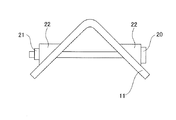
本発明の高強度部材は曲げ稜線部を有する。本発明でいう「曲げ稜線部」とは、鋼板に曲げ加工を施すことにより平板ではなくなった領域を指す。図1に示す高強度部材10の一例は、鋼板11をV字曲げ加工したものである。高強度部材10は、曲げ加工した部分の鋼板11の側面に、曲げ稜線部12を有する。曲げ稜線部12の端面13は、曲げ稜線部12の側面に位置する板厚面である。本発明でいう曲げ稜線方向D1は、曲げ稜線部12に平行な方向である。
The high-strength member of the present invention has a bent ridge line portion. The "bent ridge portion" as used in the present invention refers to a region that is no longer a flat plate due to bending of a steel plate. An example of the high-
本発明の高強度部材は、曲げ稜線部の端面の残留応力が300MPa以下であり、かつ、曲げ稜線部の端面のビッカース硬さ(HV)が200以上450以下であれば、曲げ加工の角度は特に限られない。 In the high-strength member of the present invention, if the residual stress of the end face of the bent ridge is 300 MPa or less and the Vickers hardness (HV) of the end face of the bent ridge is 200 or more and 450 or less, the bending angle is Not particularly limited.
図1に示した高強度部材10の一例は、曲げ加工した箇所が1つである例を示したが、2つ以上の箇所を曲げ加工して、2つ以上の曲げ稜線部を有することとしてもよい。
An example of the high-
<部材の引張強度が1470MPa以上>
高強度部材の引張強度(TS)は1470MPa以上である。引張強度(TS)を1470MPa以上とするためには、上記鋼板を用いることが好ましい。
本発明における引張強度(TS)及び降伏強度(YS)は、高強度部材の曲げ加工されていない部分である平坦部で測定することによって算出する。また、曲げ加工前の焼鈍鋼板(焼鈍工程後の鋼板)の引張強度(TS)及び降伏強度(YS)を測定しておけば、これらの測定値は、当該焼鈍鋼板を用いて得た高強度部材の引張強度(TS)及び降伏強度(YS)の測定値とみなせる。部材の強度は実施例に記載の方法で算出することができる。<The tensile strength of the member is 1470 MPa or more>
The tensile strength (TS) of the high-strength member is 1470 MPa or more. In order to make the tensile strength (TS) 1470 MPa or more, it is preferable to use the above steel sheet.
The tensile strength (TS) and the yield strength (YS) in the present invention are calculated by measuring on a flat portion which is an unbent portion of a high-strength member. Further, if the tensile strength (TS) and yield strength (YS) of the annealed steel sheet before bending (annealing step) are measured, these measured values are the high strengths obtained by using the annealed steel sheet. It can be regarded as a measured value of tensile strength (TS) and yield strength (YS) of a member. The strength of the member can be calculated by the method described in the examples.
<曲げ稜線部の端面の残留応力が300MPa以下>
高強度部材の曲げ稜線部の端面(板厚面)の残留応力が、300MPa以下である。これにより、曲げ稜線部の端面に亀裂が発生しにくくなるので、耐遅れ破壊特性に優れる部材を得ることができる。遅れ破壊による亀裂発生を抑制する観点から、残留応力は300MPa以下であり、好ましくは250MPa以下であり、より好ましくは200MPa以下である。下限は特に限定せず、圧縮応力となっても構わない。曲げ稜線部の端面の残留応力は、本明細書の実施例に記載するような方法で算出することができる。<Residual stress of the end face of the bent ridge is 300 MPa or less>
The residual stress of the end surface (thick surface) of the bent ridge of the high-strength member is 300 MPa or less. As a result, cracks are less likely to occur on the end face of the bent ridge line portion, so that a member having excellent delayed fracture resistance can be obtained. From the viewpoint of suppressing the generation of cracks due to delayed fracture, the residual stress is 300 MPa or less, preferably 250 MPa or less, and more preferably 200 MPa or less. The lower limit is not particularly limited, and compressive stress may be used. The residual stress of the end face of the bent ridge can be calculated by the method described in the examples of the present specification.
<曲げ稜線部の端面のビッカース硬さ(HV)が200以上450以下>
高強度部材の曲げ稜線部の端面(板厚面)のビッカース硬さ(HV)が200以上450以下である。これにより、曲げ稜線部の端面に亀裂が発生しにくくなるので、耐遅れ破壊特性に優れる部材を得ることができる。遅れ破壊による亀裂発生を抑制する観点から、硬さは450以下であり、好ましくは430以下であり、より好ましくは400以下である。また、曲げ稜線部の端面の硬さが低くなると、母材硬さとの差が大きくなるため、亀裂の発生が促進される。したがって、遅れ破壊による亀裂発生を抑制し、部材の強度を得る観点から、端面のビッカース硬さ(HV)は200以上とする。好ましくは220以上であり、より好ましくは250以上である。曲げ稜線部の端面のビッカース硬さは、本明細書の実施例に記載するような方法で算出することができる。<Vickers hardness (HV) of the end face of the bent ridge is 200 or more and 450 or less>
The Vickers hardness (HV) of the end surface (thick surface) of the bent ridge of the high-strength member is 200 or more and 450 or less. As a result, cracks are less likely to occur on the end face of the bent ridge line portion, so that a member having excellent delayed fracture resistance can be obtained. From the viewpoint of suppressing the occurrence of cracks due to delayed fracture, the hardness is 450 or less, preferably 430 or less, and more preferably 400 or less. Further, when the hardness of the end face of the bent ridge line portion becomes low, the difference from the hardness of the base metal becomes large, so that the occurrence of cracks is promoted. Therefore, the Vickers hardness (HV) of the end face is set to 200 or more from the viewpoint of suppressing the occurrence of cracks due to delayed fracture and obtaining the strength of the member. It is preferably 220 or more, and more preferably 250 or more. The Vickers hardness of the end face of the bent ridge can be calculated by a method as described in the examples of the present specification.
次に、本発明の高強度部材の製造方法の実施形態について説明する。 Next, an embodiment of the method for manufacturing a high-strength member of the present invention will be described.
本発明の高強度部材の製造方法の実施形態の一例は、引張強度が1470MPa以上の鋼板を切出し、鋼板に対して曲げ加工を施す曲げ加工工程と、切断により生じた端面を、曲げ加工の後に、400℃以上900℃以下の温度で0秒超10秒以下の条件で加熱する端面処理工程と、を有する。 An example of the embodiment of the method for manufacturing a high-strength member of the present invention is a bending step of cutting out a steel sheet having a tensile strength of 1470 MPa or more and bending the steel sheet, and after bending the end face generated by the cutting. It has an end face treatment step of heating at a temperature of 400 ° C. or higher and 900 ° C. or lower under the conditions of more than 0 seconds and 10 seconds or less.
また、本発明の高強度部材の製造方法の実施形態の他の一例は、上記成分組成及び上記ミクロ組織を有する鋼板を切出し、鋼板に対して曲げ加工を施す曲げ加工工程と、切断により生じた端面を、曲げ加工の後に、400℃以上900℃以下の温度で0秒超10秒以下の条件で加熱する端面処理工程と、を有する。 Further, another example of the embodiment of the method for manufacturing a high-strength member of the present invention is generated by a bending process of cutting out a steel sheet having the above component composition and the above microstructure and bending the steel sheet, and cutting. It has an end face treatment step of heating the end face at a temperature of 400 ° C. or higher and 900 ° C. or lower under the conditions of more than 0 seconds and 10 seconds or less after bending.
また、本発明の高強度部材の製造方法の実施形態の他の一例は、引張強度が1470MPa以上の鋼板を切出した後、切断により生じた端面を400℃以上900℃以下の温度で0秒超10秒以下の条件で加熱する端面処理工程と、端面処理工程後の鋼板に対して曲げ加工を施す曲げ加工工程と、を有する。 In another example of the embodiment of the method for manufacturing a high-strength member of the present invention, after cutting a steel sheet having a tensile strength of 1470 MPa or more, the end face generated by the cutting is cut at a temperature of 400 ° C. or higher and 900 ° C. or lower for more than 0 seconds. It has an end face treatment step of heating under a condition of 10 seconds or less, and a bending step of bending a steel sheet after the end face treatment step.
また、本発明の高強度部材の製造方法の実施形態の他の一例は、上記成分組成及び上記ミクロ組織を有する鋼板を切出した後、切断により生じた端面を400℃以上900℃以下の温度で0秒超10秒以下の条件で加熱する端面処理工程と、端面処理工程後の鋼板に対して曲げ加工を施す曲げ加工工程と、を有する。 Further, another example of the embodiment of the method for producing a high-strength member of the present invention is to cut out a steel sheet having the above-mentioned component composition and the above-mentioned microstructure, and then cut the end face generated by the cutting at a temperature of 400 ° C. or higher and 900 ° C. or lower. It has an end face treatment step of heating under conditions of more than 0 seconds and 10 seconds or less, and a bending step of bending a steel sheet after the end face treatment step.
[端面処理工程]
上述したとおり、本発明の高強度部材の製造方法は、鋼板を切出した後、切断により生じた端面を400℃以上900℃以下の温度で0秒超10秒以下の条件で加熱する端面処理工程を有する。ここで、切り出される鋼板は、例えば、引張強度が1470MPa以上の鋼板である。また、切り出される鋼板は、例えば、上記成分組成及び上記ミクロ組織を有する鋼板である。[End face treatment process]
As described above, the method for manufacturing a high-strength member of the present invention is an end face treatment step in which a steel sheet is cut out and then the end face produced by the cutting is heated at a temperature of 400 ° C. or higher and 900 ° C. or lower under conditions of more than 0 seconds and 10 seconds or less. Has. Here, the steel sheet to be cut out is, for example, a steel sheet having a tensile strength of 1470 MPa or more. The steel sheet to be cut out is, for example, a steel sheet having the above-mentioned component composition and the above-mentioned microstructure.
本発明でいう切断とは、せん断切断(機械切断)、レーザー切断、放電加工などの電気切断、ガス切断などの公知の切断を含む意味である。 The cutting in the present invention means including known cutting such as shear cutting (mechanical cutting), laser cutting, electric cutting such as electric discharge machining, and gas cutting.
端面処理工程を行うことにより、鋼板端面の残留応力を低減させ、端面を軟質化することで曲げ稜線部の端面に亀裂を生じにくくし、耐遅れ破壊特性に優れる部材を得ることができる。端面の加熱方法については特に限定されず、例えば、レーザーによる加熱がある。 By performing the end face treatment step, the residual stress of the end face of the steel sheet is reduced, and by softening the end face, cracks are less likely to occur on the end face of the bent ridge line portion, and a member having excellent delayed fracture resistance can be obtained. The method for heating the end face is not particularly limited, and for example, there is heating by a laser.
端面の残留応力を低減するために、鋼板を曲げ加工した後の成形部材の端面を、400℃以上900℃以下の温度で加熱する。加熱温度が900℃超となると、フェライトの生成及び粗大化が顕著になるため、成形部材の強度が低下し、また軟質化しすぎてしまい耐遅れ破壊特性も劣化させる。したがって、加熱温度は900℃以下であり、好ましくは870℃以下である。また、400℃未満となると、加熱能力が足りず組織の軟質化は起こらない。したがって、加熱温度は400℃以上である。好ましくは450℃以上であり、より好ましくは500℃以上であり、さらに好ましくは600℃超であり、特に好ましくは700℃以上である。加熱時間は10秒以下とする。加熱時間が10秒超となれば、組織が粗大化し耐遅れ破壊特性を劣化させる。したがって、加熱時間は10秒以下とする。好ましくは9秒以下、より好ましくは8秒以下である。組織の軟質化が起こり、端面のビッカース硬さが200以上450以下となればよく、加熱時間は特に限定されない。したがって、加熱時間は、0秒超であり、1秒以上が好ましく、2秒以上がより好ましい。 In order to reduce the residual stress of the end face, the end face of the molded member after bending the steel sheet is heated at a temperature of 400 ° C. or higher and 900 ° C. or lower. When the heating temperature exceeds 900 ° C., the formation and coarsening of ferrite becomes remarkable, so that the strength of the molded member decreases, and the molded member becomes too soft, and the delayed fracture resistance also deteriorates. Therefore, the heating temperature is 900 ° C. or lower, preferably 870 ° C. or lower. Further, when the temperature is lower than 400 ° C., the heating capacity is insufficient and the tissue is not softened. Therefore, the heating temperature is 400 ° C. or higher. It is preferably 450 ° C. or higher, more preferably 500 ° C. or higher, still more preferably 600 ° C. or higher, and particularly preferably 700 ° C. or higher. The heating time is 10 seconds or less. If the heating time exceeds 10 seconds, the structure becomes coarse and the delayed fracture resistance deteriorates. Therefore, the heating time is set to 10 seconds or less. It is preferably 9 seconds or less, more preferably 8 seconds or less. The structure may be softened and the Vickers hardness of the end face may be 200 or more and 450 or less, and the heating time is not particularly limited. Therefore, the heating time is more than 0 seconds, preferably 1 second or longer, and more preferably 2 seconds or longer.
加熱範囲は特に限定しないが、成形部材の強度を確保するために、曲げ稜線部の端面から5mm程度が好ましい。また、加熱方向は特に限定しないが、板厚方向での温度ばらつきを無くすために、板厚面と垂直方向が好ましい。 The heating range is not particularly limited, but in order to secure the strength of the molded member, it is preferably about 5 mm from the end face of the bent ridge line portion. Further, the heating direction is not particularly limited, but in order to eliminate temperature variation in the plate thickness direction, the direction perpendicular to the plate thickness surface is preferable.
[曲げ加工工程]
本発明の高強度部材の製造方法は、鋼板に対して曲げ加工を施す曲げ加工工程を有する。曲げ加工工程は、端面処理工程の前に行ってもよく、端面処理工程の後に行ってもよい。[Bending process]
The method for manufacturing a high-strength member of the present invention includes a bending process for bending a steel sheet. The bending step may be performed before the end face treatment step or after the end face treatment step.
本発明の曲げ加工は、例えば、曲げ変形、深絞り変形、張出し変形、伸びフランジ変形に分類される4つの変形様式を少なくとも一つ含む。 The bending process of the present invention includes at least one of four deformation modes classified into, for example, bending deformation, deep drawing deformation, overhang deformation, and extension flange deformation.
次に、高強度部材の製造方法により得られる高強度部材に用いる高強度部材用鋼板の製造方法の一実施形態について説明する。 Next, an embodiment of a method for manufacturing a steel plate for a high-strength member used for a high-strength member obtained by the method for manufacturing a high-strength member will be described.
また、本発明の高強度部材用鋼板の製造方法の実施形態の一例は、鋼(鋼素材)を熱間圧延する熱間圧延工程と、熱間圧延によって得られた熱延鋼板を冷間圧延する冷間圧延工程と、冷間圧延によって得られた冷延鋼板を、AC3点以上の焼鈍温度まで加熱した後、焼鈍温度から550℃までの温度域の平均冷却速度を3℃/秒以上とし、かつ冷却停止温度を350℃以下とする冷却を行い、その後、100℃以上260℃以下の温度域で20秒以上1500秒以下保持させる焼鈍工程と、を有する。Further, as an example of the embodiment of the method for manufacturing a steel plate for a high-strength member of the present invention, a hot rolling step of hot rolling a steel (steel material) and a cold rolling of a hot-rolled steel plate obtained by hot rolling are performed. After heating the cold-rolled steel sheet obtained by the cold rolling process to a annealing temperature of 3 points or more in AC, the average cooling rate in the temperature range from the annealing temperature to 550 ° C is 3 ° C / sec or more. It also has an annealing step of performing cooling so that the cooling stop temperature is 350 ° C. or lower, and then holding the material in a temperature range of 100 ° C. or higher and 260 ° C. or lower for 20 seconds or longer and 1500 ° C. or lower.
以下、これらの工程と、熱間圧延工程前に行う好ましい鋳造工程について説明する。なお、以下に示す温度は、特に説明がない限り、鋼素材(スラブ)、鋼板等の表面温度を意味する。 Hereinafter, these steps and a preferable casting step performed before the hot rolling step will be described. Unless otherwise specified, the temperatures shown below mean the surface temperatures of steel materials (slabs), steel plates, and the like.
[鋳造工程]
前述した成分組成を有する鋼を鋳造する。鋳造速度は特に限定しないが、上記の介在物の生成を抑え、耐遅れ破壊特性を向上させるために、鋳造速度は1.80m/分以下が好ましく、1.75m/分以下がより好ましく、1.70m/分以下がさらに好ましい。下限も特に限定しないが、生産性の観点から、好ましくは1.25m/分以上であり、より好ましくは1.30m/分以上である。[Casting process]
A steel having the above-mentioned composition is cast. The casting speed is not particularly limited, but the casting speed is preferably 1.80 m / min or less, more preferably 1.75 m / min or less, in order to suppress the formation of the above-mentioned inclusions and improve the delayed fracture resistance. More preferably .70 m / min or less. The lower limit is not particularly limited, but from the viewpoint of productivity, it is preferably 1.25 m / min or more, and more preferably 1.30 m / min or more.
[熱間圧延工程]
熱間圧延工程では、例えば、前述した成分組成を有する鋼素材(スラブ)を、熱間圧延する。スラブ加熱温度は特に限定されないが、スラブ加熱温度を1200℃以上とすることで、硫化物の固溶促進とMn偏析の軽減が図られ、上記した粗大な介在物量の低減が図られ、耐遅れ破壊特性が向上する傾向がある。このため、スラブ加熱温度は1200℃以上が好ましい。より好ましくは1220℃以上である。また、スラブ加熱時の加熱速度は5〜15℃/分が好ましく、スラブ均熱時間は30〜100分が好ましい。[Hot rolling process]
In the hot rolling step, for example, a steel material (slab) having the above-mentioned composition is hot-rolled. The slab heating temperature is not particularly limited, but by setting the slab heating temperature to 1200 ° C. or higher, the solid solution of sulfides can be promoted and the Mn segregation can be reduced, the amount of coarse inclusions described above can be reduced, and the delay tolerance can be reduced. Destructive properties tend to improve. Therefore, the slab heating temperature is preferably 1200 ° C. or higher. More preferably, it is 1220 ° C. or higher. The heating rate during slab heating is preferably 5 to 15 ° C./min, and the slab heating time is preferably 30 to 100 minutes.
仕上げ圧延終了温度は840℃以上が好ましい。仕上げ圧延終了温度が840℃未満では、温度の低下までに時間がかかり、介在物が生成することで耐遅れ破壊特性を劣化させるのみならず、鋼板の内部の品質も低下する可能性がある。したがって、仕上げ圧延終了温度は好ましくは840℃以上であり、より好ましくは860℃以上である。一方、上限は特に限定しないが、後の巻き取り温度までの冷却が困難になるため、仕上げ圧延終了温度は好ましくは950℃以下であり、より好ましくは920℃以下である。 The finish rolling end temperature is preferably 840 ° C. or higher. If the finish rolling end temperature is less than 840 ° C., it takes time for the temperature to decrease, and inclusions may not only deteriorate the delayed fracture resistance but also deteriorate the internal quality of the steel sheet. Therefore, the finish rolling end temperature is preferably 840 ° C. or higher, more preferably 860 ° C. or higher. On the other hand, although the upper limit is not particularly limited, the finish rolling end temperature is preferably 950 ° C. or lower, more preferably 920 ° C. or lower, because cooling to the subsequent winding temperature becomes difficult.
冷却された熱延鋼板は630℃以下の温度で巻き取るのが好ましい。巻き取り温度が630℃超では、地鉄表面が脱炭するおそれがあり、鋼板内部と表面で組織差が生じ合金濃度ムラの原因となる可能性がある。また表層の脱炭により、鋼中表層の炭化物を有するベイナイトやマルテンサイトの面積率が減少するため、所望の強度を確保するのが難しくなる傾向がある。したがって、巻き取り温度は好ましくは630℃以下であり、より好ましくは600℃以下である。巻き取り温度の下限は特に限定されないが、冷間圧延性の低下を防ぐために500℃以上が好ましい。 The cooled hot-rolled steel sheet is preferably wound at a temperature of 630 ° C. or lower. If the winding temperature exceeds 630 ° C., the surface of the base iron may be decarburized, which may cause a structure difference between the inside and the surface of the steel sheet and cause uneven alloy concentration. Further, decarburization of the surface layer reduces the area ratio of bainite and martensite having carbides on the surface layer of the steel, so that it tends to be difficult to secure the desired strength. Therefore, the winding temperature is preferably 630 ° C. or lower, more preferably 600 ° C. or lower. The lower limit of the winding temperature is not particularly limited, but is preferably 500 ° C. or higher in order to prevent deterioration of cold rollability.
[冷間圧延工程]
冷間圧延工程では、熱間圧延により得られた熱延鋼板を冷間圧延する。冷間圧延工程では、例えば、上述のように巻き取られた熱延鋼板を酸洗した後、冷間圧延し、冷延鋼板を製造する。酸洗の条件は特に限定はされない。圧下率が20%未満の場合、表面の平坦度が悪く、組織が不均一となる危険性があるので、圧下率は、好ましくは20%以上であり、より好ましくは30%以上であり、さらに好ましくは40%以上である。[Cold rolling process]
In the cold rolling step, the hot-rolled steel sheet obtained by hot rolling is cold-rolled. In the cold rolling step, for example, the hot-rolled steel sheet wound as described above is pickled and then cold-rolled to produce a cold-rolled steel sheet. The pickling conditions are not particularly limited. If the reduction rate is less than 20%, the flatness of the surface is poor and there is a risk that the structure becomes uneven. Therefore, the reduction rate is preferably 20% or more, more preferably 30% or more, and further. It is preferably 40% or more.
[焼鈍工程]
冷間圧延によって得られた冷延鋼板を、AC3点以上の焼鈍温度に加熱する。焼鈍温度がAC3点未満では、組織にフェライトが生成し、所望の強度を得ることができない。したがって、焼鈍温度はAC3点以上であり、好ましくはAC3点+10℃以上であり、より好ましくはAC3点+20℃以上である。焼鈍温度の上限は特に限定されないが、オーステナイトの粗大化を抑制し、耐遅れ破壊特性の劣化を防ぐ観点から、焼鈍温度は900℃以下が好ましい。なお、AC3点以上の焼鈍温度まで加熱した後に、当該焼鈍温度で均熱してもよい。[Annealing process]
The cold-rolled steel sheet obtained by cold rolling is heated to an annealing temperature of 3 points or more in AC. If the annealing temperature is less than 3 points AC, ferrite is formed in the structure and the desired strength cannot be obtained. Therefore, the annealing temperature is AC 3 points or more, preferably AC 3 points + 10 ° C. or higher, and more preferably AC 3 points + 20 ° C. or higher. The upper limit of the annealing temperature is not particularly limited, but the annealing temperature is preferably 900 ° C. or lower from the viewpoint of suppressing coarsening of austenite and preventing deterioration of delayed fracture resistance. After heating to an annealing temperature of 3 points or more in AC, the heating may be equalized at the annealing temperature.
AC3点は以下の式により算出する。また、下記式において(%元素記号)は各元素の含有量(質量%)を意味する。
AC3点(℃)=910−203√(%C)+45(%Si)−30(%Mn)−20(%Cu)−15(%Ni)+11(%Cr)+32(%Mo)+104(%V)+400(%Ti)+460(%Al)The AC3 points are calculated by the following formula. Further, in the following formula, (% element symbol) means the content (mass%) of each element.
AC 3 points (° C) = 910-203√ (% C) +45 (% Si) -30 (% Mn) -20 (% Cu) -15 (% Ni) +11 (% Cr) +32 (% Mo) +104 ( % V) + 400 (% Ti) + 460 (% Al)
上記のとおり冷延鋼板をAC3点以上の焼鈍温度まで加熱した後、当該焼鈍温度から550℃までの温度域の平均冷却速度を3℃/秒以上とし、かつ冷却停止温度を350℃以下とする冷却を行い、その後、100℃以上260℃以下の温度域で20秒以上1500秒以下保持させる。After heating the cold-rolled steel plate to a annealing temperature of 3 points or more AC as described above, the average cooling rate in the temperature range from the annealing temperature to 550 ° C is set to 3 ° C / sec or more, and the cooling stop temperature is set to 350 ° C or less. After that, it is held in a temperature range of 100 ° C. or higher and 260 ° C. or lower for 20 seconds or longer and 1500 seconds or shorter.
焼鈍温度から550℃までの温度域の平均冷却速度が3℃/秒未満では、フェライトの過度な生成を招くため所望の強度を得ることが難しくなる。また表層にフェライトが生成することで、表層付近の炭化物を有するベイナイトやマルテンサイト分率を得ることが難しくなり、耐遅れ破壊特性を劣化させる。したがって、焼鈍温度から550℃までの温度域の平均冷却速度は、3℃/秒以上であり、好ましくは5℃/秒以上であり、より好ましくは10℃/秒以上である。なお、平均冷却速度の上限は特に規定されないが、早くなりすぎるとコイル幅方向でマルテンサイト変態の不均一化が起こりやすくなり、形状劣化により鋼板が設備へ接触するおそれがあるため、最低限の形状を得る観点から、3000℃/s以下とすることが好ましい。 If the average cooling rate in the temperature range from the annealing temperature to 550 ° C. is less than 3 ° C./sec, it becomes difficult to obtain the desired strength because excessive formation of ferrite is caused. Further, since ferrite is formed on the surface layer, it becomes difficult to obtain a bainite or martensite fraction having carbides near the surface layer, and the delayed fracture resistance is deteriorated. Therefore, the average cooling rate in the temperature range from the annealing temperature to 550 ° C. is 3 ° C./sec or more, preferably 5 ° C./sec or more, and more preferably 10 ° C./sec or more. The upper limit of the average cooling rate is not particularly specified, but if it is too fast, non-uniformity of martensitic transformation tends to occur in the coil width direction, and the steel sheet may come into contact with the equipment due to shape deterioration, so it is the minimum. From the viewpoint of obtaining the shape, the temperature is preferably 3000 ° C./s or less.
焼鈍温度から550℃までの温度域の平均冷却速度は、特に断らない限り、「(焼鈍温度−550℃)/(焼鈍温度から550℃までの冷却時間)」である。 Unless otherwise specified, the average cooling rate in the temperature range from the annealing temperature to 550 ° C. is "(annealing temperature -550 ° C.) / (cooling time from the annealing temperature to 550 ° C.)".
冷却停止温度は350℃以下である。冷却停止温度が350℃超となると、十分に焼戻しが進行せず、最終組織に焼入れままのマルテンサイトや残留オーステナイトが生成し、曲げ稜線部の端面の硬さが高くなることで耐遅れ破壊特性が劣化する。したがって、優れた耐遅れ破壊特性を得るために、冷却停止温度は350℃以下であり、好ましくは300℃以下、より好ましくは250℃以下である。なお、冷却停止温度の下限は特に限定しないが、その後再加熱したときの温度を確保しやすくする観点から0℃以上が好ましい。 The cooling stop temperature is 350 ° C. or lower. When the cooling stop temperature exceeds 350 ° C, tempering does not proceed sufficiently, martensite and retained austenite as hardened are generated in the final structure, and the hardness of the end face of the bent ridge increases, resulting in delayed fracture resistance. Deteriorates. Therefore, in order to obtain excellent delayed fracture resistance, the cooling stop temperature is 350 ° C. or lower, preferably 300 ° C. or lower, and more preferably 250 ° C. or lower. The lower limit of the cooling stop temperature is not particularly limited, but is preferably 0 ° C. or higher from the viewpoint of facilitating securing the temperature when reheating is performed thereafter.
ベイナイト内部に分布する炭化物は、焼入れ後の低温域での保持中に生成する炭化物であり、水素のトラップサイトとなることで水素を捕捉し、耐遅れ破壊特性の劣化を防ぐことができる。保持温度が100℃未満、又は、保持時間が20秒未満になると、ベイナイトが生成せず、また炭化物を含まない焼入れままのマルテンサイトが生成するため、曲げ稜線部の端面の硬さが高くなり、上記の効果が得られなくなる。 The carbides distributed inside bainite are carbides generated during retention in a low temperature region after quenching, and by acting as hydrogen trap sites, hydrogen can be trapped and deterioration of delayed fracture resistance can be prevented. If the holding temperature is less than 100 ° C. or the holding time is less than 20 seconds, bainite is not formed and hardened martensite containing no carbide is formed, so that the hardness of the end face of the bent ridge becomes high. , The above effect cannot be obtained.
また、保持温度が260℃超、又は、保持時間が1500秒超となると、脱炭し、さらにベイナイト内部に粗大な炭化物が生成するため、軟質化しすぎてしまい耐遅れ破壊特性を劣化させる。 Further, when the holding temperature exceeds 260 ° C. or the holding time exceeds 1500 seconds, decarburization is performed and coarse carbides are generated inside the bainite, which causes excessive softening and deteriorates the delayed fracture resistance.
したがって、保持温度は100℃以上260℃以下であり、保持時間は20秒以上1500秒以下である。また、保持温度は好ましくは130℃以上240℃以下であり、保持時間は、好ましくは50秒以上、1000秒以下である。 Therefore, the holding temperature is 100 ° C. or higher and 260 ° C. or lower, and the holding time is 20 seconds or longer and 1500 seconds or lower. The holding temperature is preferably 130 ° C. or higher and 240 ° C. or lower, and the holding time is preferably 50 seconds or longer and 1000 seconds or lower.
なお、本発明における保持とは、一定の温度での保持のみだけではなく、本発明の保持温度の範囲内で変化する場合も含むものとする。 It should be noted that the holding in the present invention includes not only holding at a constant temperature but also a case where the temperature changes within the holding temperature of the present invention.
なお、熱間圧延後の熱延鋼板には、組織軟質化のための熱処理をおこなってもよい。また、鋼板表面にZnやAlなどのめっきが施されていても構わない。また、焼鈍冷却後又はめっき処理後は形状調整のための調質圧延を行ってもよい。 The hot-rolled steel sheet after hot rolling may be heat-treated to soften the structure. Further, the surface of the steel sheet may be plated with Zn, Al, or the like. Further, after annealing cooling or plating treatment, temper rolling for shape adjustment may be performed.
本発明を、実施例を参照しながら具体的に説明するが、本発明はこれらに限定されるものではない。 The present invention will be specifically described with reference to Examples, but the present invention is not limited thereto.
[実施例1]
表1に記載の引張強度を有する鋼板を30mm×110mmの小片にせん断した。なお、引張試験は、鋼板の圧延方向から、標点間距離50mm、標点間幅25mm、板厚1.4mmのJIS5号試験片を採取し、JISZ2241に準拠し、引張速度が10mm/分で引張試験を行った。測定した引張強度(TS)及び降伏強度(YS)は表1に示す。
せん断後の一部の鋼板については、切断により生じた端面に対して表1に示す条件で端面処理を施した。次に、90°の角度を有するダイスの上に鋼板のサンプルを載せて、90°の角度を有するポンチによって鋼板をプレスすることで、V字曲げ加工を行った。次いで、図2に側面図を示すように、ボルト20、ナット21及びテーパーワッシャー22を用いて、曲げ加工後の鋼板(部材)を、鋼板11の板面の両側からボルト20で締め込んだ。CAE(Computer Aided Engineering)解析によって、負荷応力と締込量の関係を算出し、締込量と臨界負荷応力が一致するようにした。臨界負荷応力は、後述する方法で測定した。次に、一部の曲げ加工後の鋼板(部材)については、鋼板の端面に対して、表1に示す条件で端面処理を施した。端面処理の各条件は表1に示す。表1の端面処理で、熱処理温度(℃)の欄を「−」と記載したものは、熱処理しなかったことを意味する。[Example 1]
The steel sheet having the tensile strength shown in Table 1 was sheared into small pieces of 30 mm × 110 mm. In the tensile test, JIS No. 5 test pieces with a distance between gauge points of 50 mm, a width between gauge points of 25 mm, and a plate thickness of 1.4 mm were collected from the rolling direction of the steel sheet, and in accordance with JISZ2241, the tensile speed was 10 mm / min. A tensile test was performed. The measured tensile strength (TS) and yield strength (YS) are shown in Table 1.
For some of the steel sheets after shearing, the end faces generated by cutting were subjected to end face treatment under the conditions shown in Table 1. Next, a sample of the steel sheet was placed on a die having an angle of 90 °, and the steel sheet was pressed by a punch having an angle of 90 ° to perform a V-shaped bending process. Next, as shown in the side view in FIG. 2, the bent steel plate (member) was tightened with
2.評価方法
各種製造条件で得られた部材に対して、遅れ破壊試験によって測定した臨界負荷応力で耐遅れ破壊特性を評価した。また、部材の端面の残留応力とビッカース硬さを以下のように測定した。各評価の方法は次のとおりである。2. Evaluation method The delayed fracture resistance was evaluated by the critical load stress measured by the delayed fracture test for the members obtained under various manufacturing conditions. In addition, the residual stress and Vickers hardness of the end face of the member were measured as follows. The method of each evaluation is as follows.
(臨界負荷応力の測定)
遅れ破壊試験によって臨界負荷応力を測定した。具体的には、各製造条件で得られた部材をpH=1(25℃)の塩酸中に浸漬し、遅れ破壊しない最大負荷応力を臨界負荷応力として評価した。遅れ破壊の判定は目視及び実体顕微鏡で倍率×20まで拡大した画像にて行い、96時間浸漬し割れが発生しなかった場合を破壊なしとした。ここでいう割れとは、亀裂長さが200μm以上の亀裂が発生した場合を指す。(Measurement of critical load stress)
The critical load stress was measured by a delayed rupture test. Specifically, the members obtained under each production condition were immersed in hydrochloric acid having a pH of 1 (25 ° C.), and the maximum load stress that did not cause delayed fracture was evaluated as the critical load stress. The judgment of delayed fracture was performed visually and with an image magnified to a magnification of 20 with a stereomicroscope, and the case where the image was immersed for 96 hours and no cracks occurred was regarded as no destruction. The term “crack” as used herein refers to the case where a crack having a crack length of 200 μm or more occurs.
(端面の残留応力の測定)
各製造条件で得られた部材について、X線回折により端面の残留応力を測定した。残留応力の測定箇所は、曲げ稜線部の端面の板厚中心であり、X線の照射径は150μmとした。測定方向は、板厚方向に垂直かつ曲げ稜線方向に垂直な方向とした。図3は、曲げ稜線部の端面の拡大図であり、板厚中心C1及び測定方向D2にそれぞれ符号を付して示している。(Measurement of residual stress on the end face)
For the members obtained under each manufacturing condition, the residual stress on the end face was measured by X-ray diffraction. The measurement point of the residual stress was the center of the plate thickness of the end face of the bent ridge line portion, and the X-ray irradiation diameter was set to 150 μm. The measurement direction was perpendicular to the plate thickness direction and perpendicular to the bending ridge line direction. FIG. 3 is an enlarged view of the end face of the bent ridge line portion, and is shown with reference numerals at the plate thickness center C1 and the measurement direction D2, respectively.
(端面のビッカース硬さの測定)
各製造条件で得られた部材について、ビッカース硬さ試験により端面のビッカース硬さ(HV)を測定した。ビッカース硬さの測定箇所は、曲げ稜線部の端面を曲げ稜線方向D1方向に切断し、鏡面研磨したその断面の板厚中心において、端面から100μmの箇所とした。測定荷重は1kgfとした。(Measurement of Vickers hardness of end face)
The Vickers hardness (HV) of the end face was measured by the Vickers hardness test for the members obtained under each manufacturing condition. The Vickers hardness was measured at a position 100 μm from the end face at the center of the thickness of the cross section obtained by cutting the end face of the bent ridge line portion in the bending ridge line direction D1 direction and mirror-polishing the end face. The measured load was 1 kgf.
3.評価結果
評価結果を表1に示す。3. 3. Evaluation Results The evaluation results are shown in Table 1.

TS≧1470MPa、かつ、臨界負荷応力≧1.10×YSの部材を合格とし、表1に発明例として示した。また、TS<1470MPa、又は、臨界負荷応力<1.10×YSの部材を不合格とし、表1に比較例として示した。なお、表1において、「臨界負荷応力/YS」が1.10以上であることが、臨界負荷応力≧1.10×YSであることを意味する。表1に示すように、本発明例の部材は、高強度で、かつ耐遅れ破壊特性に優れている。 A member having TS ≧ 1470 MPa and critical load stress ≧ 1.10 × YS was accepted, and is shown as an example of the invention in Table 1. Further, a member having TS <1470 MPa or critical load stress <1.10 × YS was rejected and is shown as a comparative example in Table 1. In Table 1, when "critical load stress / YS" is 1.10 or more, it means that critical load stress ≥ 1.10 × YS. As shown in Table 1, the members of the examples of the present invention have high strength and excellent delayed fracture resistance.
[実施例2]
1.評価用部材の製造
表2に示す成分組成を有し、残部がFe及び不可避的不純物よりなる鋼を真空溶解炉にて溶製後、分塊圧延し27mm厚の分塊圧延材を得た。得られた分塊圧延材を板厚4.2mm厚まで熱間圧延し、熱延鋼板を製造した。次いで、熱延鋼板を研削加工し、板厚3.2mmにした後、板厚2.4〜1.12mmまで冷間圧延し、冷延鋼板を製造した。次いで、上記により得られた冷延鋼板に、表3及び表4に示す条件で熱処理を行った(焼鈍工程)。なお、表2の成分組成の空欄は、その成分を意図的に添加していないことを表しており、含有しない(0質量%)場合だけでなく、不可避的に含有する場合も含む。なお、熱間圧延工程、冷間圧延工程、焼鈍工程の各条件の詳細は表3及び表4に示す。[Example 2]
1. 1. Production of Evaluation Member A steel having the composition shown in Table 2 and having the balance of Fe and unavoidable impurities was melted in a vacuum melting furnace and then lump-rolled to obtain a lump-rolled material having a thickness of 27 mm. The obtained lump-rolled material was hot-rolled to a thickness of 4.2 mm to produce a hot-rolled steel sheet. Next, the hot-rolled steel sheet was ground to a plate thickness of 3.2 mm and then cold-rolled to a plate thickness of 2.4 to 1.12 mm to produce a cold-rolled steel sheet. Next, the cold-rolled steel sheet obtained as described above was heat-treated under the conditions shown in Tables 3 and 4 (annealing step). The blanks in the component composition in Table 2 indicate that the component was not intentionally added, and include not only the case where the component is not contained (0% by mass) but also the case where the component is unavoidably contained. Details of each condition of the hot rolling process, the cold rolling process, and the annealing process are shown in Tables 3 and 4.
熱処理後の鋼板を30mm×110mmの小片にせん断し、90°の角度を有するダイスの上に鋼板のサンプルを載せて、90°の角度を有するポンチによって鋼板をプレスすることで、V字曲げ加工を行った。次いで、図2に側面図を示すように、ボルト20、ナット21及びテーパーワッシャー22を用いて、曲げ加工後の鋼板(部材)を、鋼板11の板面の両側からボルト20で締め込んだ。CAE(Computer Aided Engineering)解析によって、負荷応力と締込量の関係を算出し、締込量と臨界負荷応力が一致するようにした。臨界負荷応力は、後述する方法で測定した。
The heat-treated steel sheet is sheared into small pieces of 30 mm x 110 mm, a sample of the steel sheet is placed on a die with an angle of 90 °, and the steel sheet is pressed with a punch with an angle of 90 ° to perform V-shaped bending. Was done. Next, as shown in the side view in FIG. 2, the bent steel plate (member) was tightened with
表3及び表4のNo.1〜72は、曲げ加工の後、種々の温度で曲げ稜線部の端面を加熱した。表4のNo.73は、鋼板を小片にせん断した後、上記曲げ加工を行う前に、切断により生じた端面を加熱した。端面処理の各条件は、表3及び表4に示す。表3及び表4の端面処理で、熱処理温度(℃)の欄を「−」と記載したものは、熱処理しなかったことを意味する。 Tables 3 and 4 No. In Nos. 1 to 72, after the bending process, the end faces of the bent ridges were heated at various temperatures. No. in Table 4 73 heated the end face generated by cutting after shearing the steel sheet into small pieces and before performing the bending process. Each condition of the end face treatment is shown in Tables 3 and 4. In the end face treatments of Tables 3 and 4, the heat treatment temperature (° C.) column described as "-" means that the heat treatment was not performed.
2.評価方法
各種製造条件で得られた部材に対して、鋼組織(ミクロ組織)を解析することで組織分率を調査した。また、引張試験を実施することで引張強度等の引張特性を評価し、遅れ破壊試験によって測定した臨界負荷応力で耐遅れ破壊特性を評価した。また、部材の端面の残留応力とビッカース硬さを以下のように測定した。各評価の方法は次のとおりである。2. Evaluation method The structure fraction was investigated by analyzing the steel structure (microstructure) of the members obtained under various manufacturing conditions. In addition, tensile properties such as tensile strength were evaluated by conducting a tensile test, and delayed fracture resistance was evaluated by the critical load stress measured by the delayed fracture test. In addition, the residual stress and Vickers hardness of the end face of the member were measured as follows. The method of each evaluation is as follows.
(平均粒径が50nm以下の炭化物を含有するベイナイト及び平均粒径が50nm以下の炭化物を含有するマルテンサイトの1種又は2種の面積率の合計)
焼鈍工程で得られた鋼板(以下、焼鈍鋼板という。)に対して垂直方向から試験片を採取し、圧延方向に平行な板厚L断面を鏡面研磨し、ナイタール液で組織現出した後、走査電子顕微鏡を用いて観察し、倍率1500倍のSEM像上の、実長さ82μm×57μmの領域上に4.8μm間隔の16mm×15mmの格子をおき、各相上にある点数を数えるポイントカウンティング法により、平均粒径が50nm以下の炭化物を含有するマルテンサイト及び平均粒径が50nm以下の炭化物を含有するベイナイトの面積率を計算し、それらの合計の面積率を算出した。面積率は、倍率1500倍の別々のSEM像から求めた3つの面積率の平均値とした。マルテンサイトは白色の組織を呈しており、ベイナイトは黒色の組織の内部に微細な炭化物が析出している。炭化物の平均粒径は以下のように算出した。また、面積率は、観察範囲全体に対する面積率であり、これを鋼板組織全体に対する面積率とみなした。(Total area ratio of one or two types of bainite containing carbides with an average particle size of 50 nm or less and martensite containing carbides with an average particle size of 50 nm or less)
A test piece is collected from the direction perpendicular to the steel sheet obtained in the annealing process (hereinafter referred to as annealed steel sheet), the plate thickness L cross section parallel to the rolling direction is mirror-polished, and the structure is revealed with a nital solution. A point for counting the points on each phase by observing with a scanning electron microscope and placing a 16 mm × 15 mm grid with 4.8 μm intervals on a region with an actual length of 82 μm × 57 μm on an SEM image with a magnification of 1500 times. By the counting method, the area ratios of martensite containing carbides having an average particle size of 50 nm or less and bainite containing carbides having an average particle size of 50 nm or less were calculated, and the total area ratios thereof were calculated. The area ratio was the average value of the three area ratios obtained from separate SEM images with a magnification of 1500 times. Martensite has a white structure, and bainite has fine carbides precipitated inside the black structure. The average particle size of the carbide was calculated as follows. The area ratio is the area ratio with respect to the entire observation range, and this is regarded as the area ratio with respect to the entire steel sheet structure.
(ベイナイト及びマルテンサイト中の炭化物の平均粒径)
焼鈍鋼板の圧延方向に対して垂直方向から試験片を採取し、圧延方向に平行な板厚L断面を鏡面研磨し、ナイタール液で組織現出した後、走査電子顕微鏡を用いて観察し、倍率5000倍のSEM像上の炭化物の総面積を二値化による画像解析にて測定し、その総面積を個数平均することで炭化物1個あたりの平均面積を算出した。炭化物1個あたりの平均面積から求めた円相当直径を平均粒径とした。(Average particle size of carbides in bainite and martensite)
Specimens are collected from the direction perpendicular to the rolling direction of the annealed steel sheet, the plate thickness L cross section parallel to the rolling direction is mirror-polished, the structure is revealed with a nital solution, and then observed using a scanning electron microscope. The total area of the charcoal on the 5000 times SEM image was measured by image analysis by binarization, and the average area per charcoal was calculated by averaging the total area. The diameter equivalent to a circle obtained from the average area per carbide was defined as the average particle size.
(引張試験)
焼鈍鋼板の圧延方向から、標点間距離50mm、標点間幅25mm、板厚1.4mmのJIS5号試験片を採取し、JISZ2241に準拠し、引張速度が10mm/分で引張試験を行い、引張強度(TS)及び降伏強度(YS)を測定した。(Tensile test)
From the rolling direction of the annealed steel sheet, JIS No. 5 test pieces with a distance between gauge points of 50 mm, a width between gauge points of 25 mm, and a plate thickness of 1.4 mm were collected, and a tensile test was performed at a tensile speed of 10 mm / min in accordance with JISZ2241. Tensile strength (TS) and yield strength (YS) were measured.
(臨界負荷応力の測定)
遅れ破壊試験によって臨界負荷応力を測定した。具体的には、各製造条件で得られた部材をpH=1(25℃)の塩酸中に浸漬し、遅れ破壊しない最大負荷応力を臨界負荷応力として評価した。遅れ破壊の判定は目視及び実体顕微鏡で倍率×20まで拡大した画像にて行い、96時間浸漬し割れが発生しなかった場合を破壊なしとした。ここでいう割れとは、亀裂長さが200μm以上の亀裂が発生した場合を指す。(Measurement of critical load stress)
The critical load stress was measured by a delayed rupture test. Specifically, the members obtained under each production condition were immersed in hydrochloric acid having a pH of 1 (25 ° C.), and the maximum load stress that did not cause delayed fracture was evaluated as the critical load stress. The judgment of delayed fracture was performed visually and with an image magnified to a magnification of 20 with a stereomicroscope, and the case where the image was immersed for 96 hours and no cracks occurred was regarded as no destruction. The term “crack” as used herein refers to the case where a crack having a crack length of 200 μm or more occurs.
(端面の残留応力の測定)
各製造条件で得られた部材について、X線回折により端面の残留応力を測定した。残留応力の測定箇所は、曲げ稜線部の端面の板厚中心であり、X線の照射径は150μmとした。測定方向は、板厚方向に垂直かつ曲げ稜線方向に垂直な方向とした。図3は、曲げ稜線部の端面の拡大図であり、板厚中心C1及び測定方向D2にそれぞれ符号を付して示している。(Measurement of residual stress on the end face)
For the members obtained under each manufacturing condition, the residual stress on the end face was measured by X-ray diffraction. The measurement point of the residual stress was the center of the plate thickness of the end face of the bent ridge line portion, and the X-ray irradiation diameter was set to 150 μm. The measurement direction was perpendicular to the plate thickness direction and perpendicular to the bending ridge line direction. FIG. 3 is an enlarged view of the end face of the bent ridge line portion, and is shown with reference numerals at the plate thickness center C1 and the measurement direction D2, respectively.
(端面のビッカース硬さの測定)
各製造条件で得られた部材について、ビッカース硬さ試験により端面のビッカース硬さ(HV)を測定した。ビッカース硬さの測定箇所は、曲げ稜線部の端面を曲げ稜線方向D1方向に切断し、鏡面研磨したその断面の板厚中心において、端面から100μmの箇所とした。測定荷重は1kgfとした。(Measurement of Vickers hardness of end face)
The Vickers hardness (HV) of the end face was measured by the Vickers hardness test for the members obtained under each manufacturing condition. The Vickers hardness was measured at a position 100 μm from the end face at the center of the thickness of the cross section obtained by cutting the end face of the bent ridge line portion in the bending ridge line direction D1 direction and mirror-polishing the end face. The measured load was 1 kgf.
3.評価結果
上記評価結果を表5及び表6に示す。3. 3. Evaluation Results The above evaluation results are shown in Tables 5 and 6.
本実施例では、TS≧1470MPa、かつ、臨界負荷応力≧1.10×YSの部材を合格とし、表5及び表6に発明例として示した。また、TS<1470MPa、又は、臨界負荷応力<1.10×YSの部材を不合格とし、表5及び表6に比較例として示した。なお、表5及び表6において、「臨界負荷応力/YS」が1.10以上であることが、臨界負荷応力≧1.10×YSであることを意味する。表5及び表6に示すように、本発明例の部材は、高強度で、かつ耐遅れ破壊特性に優れている。 In this example, a member having TS ≧ 1470 MPa and critical load stress ≧ 1.10 × YS was accepted, and is shown as an example of invention in Tables 5 and 6. Further, the members having TS <1470 MPa or critical load stress <1.10 × YS were rejected and are shown as comparative examples in Tables 5 and 6. In Tables 5 and 6, when "critical load stress / YS" is 1.10 or more, it means that critical load stress ≥ 1.10 × YS. As shown in Tables 5 and 6, the members of the examples of the present invention have high strength and excellent delayed fracture resistance.
[実施例3]
実施例3では、Sbを含有しない鋼種で部材を製造して評価した。
1.評価用部材の製造
表7示す成分組成を有し、残部がFe及び不可避的不純物よりなる鋼を真空溶解炉にて溶製後、分塊圧延し27mm厚の分塊圧延材を得た。得られた分塊圧延材を板厚4.2mm厚まで熱間圧延し、熱延鋼板を製造した。次いで、熱延鋼板を研削加工し、板厚3.2mmにした後、板厚2.4〜1.12mmまで冷間圧延し、冷延鋼板を製造した。次いで、上記により得られた冷延鋼板に、表8に示す条件で熱処理を行った(焼鈍工程)。なお、表7の成分組成の空欄は、その成分を意図的に添加していないことを表しており、含有しない(0質量%)場合だけでなく、不可避的に含有する場合も含む。なお、熱間圧延工程、冷間圧延工程、焼鈍工程の各条件の詳細は表8に示す。[Example 3]
In Example 3, a member was manufactured from a steel grade containing no Sb and evaluated.
1. 1. Production of Evaluation Member A steel having the composition shown in Table 7 and having the balance of Fe and unavoidable impurities was melted in a vacuum melting furnace and then lump-rolled to obtain a lump-rolled material having a thickness of 27 mm. The obtained lump-rolled material was hot-rolled to a thickness of 4.2 mm to produce a hot-rolled steel sheet. Next, the hot-rolled steel sheet was ground to a plate thickness of 3.2 mm and then cold-rolled to a plate thickness of 2.4 to 1.12 mm to produce a cold-rolled steel sheet. Next, the cold-rolled steel sheet obtained as described above was heat-treated under the conditions shown in Table 8 (annealing step). The blanks in the component composition in Table 7 indicate that the component is not intentionally added, and includes not only the case where the component is not contained (0% by mass) but also the case where the component is unavoidably contained. The details of each condition of the hot rolling step, the cold rolling step, and the annealing step are shown in Table 8.
熱処理後の鋼板を30mm×110mmの小片にせん断し、90°の角度を有するダイスの上に鋼板のサンプルを載せて、90°の角度を有するポンチによって鋼板をプレスすることで、V字曲げ加工を行った。次いで、図2に側面図を示すように、ボルト20、ナット21及びテーパーワッシャー22を用いて、曲げ加工後の鋼板(部材)を、鋼板11の板面の両側からボルト20で締め込んだ。CAE(Computer Aided Engineering)解析によって、負荷応力と締込量の関係を算出し、締込量と臨界負荷応力が一致するようにした。臨界負荷応力は、実施例2に記載の方法で測定した。
The heat-treated steel sheet is sheared into small pieces of 30 mm x 110 mm, a sample of the steel sheet is placed on a die with an angle of 90 °, and the steel sheet is pressed with a punch with an angle of 90 ° to perform V-shaped bending. Was done. Next, as shown in the side view in FIG. 2, the bent steel plate (member) was tightened with
曲げ加工の後、種々の温度で曲げ稜線部の端面を加熱した。端面処理の各条件は、表8に示す。 After the bending process, the end face of the bent ridge was heated at various temperatures. Each condition of the end face treatment is shown in Table 8.
2.評価方法
各種製造条件で得られた部材に対して、実施例2と同様に、部材の測定及び評価を行った。2. Evaluation Method The members obtained under various manufacturing conditions were measured and evaluated in the same manner as in Example 2.
3.評価結果
評価結果を表9に示す。3. 3. Evaluation Results The evaluation results are shown in Table 9.
本実施例では、TS≧1470MPa、かつ、臨界負荷応力≧1.10×YSの部材を合格とし、表9に発明例として示した。また、TS<1470MPa、又は、臨界負荷応力<1.10×YSの部材を不合格とし、表9に比較例として示した。なお、表9において、「臨界負荷応力/YS」が1.10以上であることが、臨界負荷応力≧1.10×YSであることを意味する。表9に示すように、本発明例の部材は、高強度で、かつ耐遅れ破壊特性に優れている。 In this example, a member having TS ≧ 1470 MPa and critical load stress ≧ 1.10 × YS was accepted, and is shown as an example of invention in Table 9. Further, a member having TS <1470 MPa or critical load stress <1.10 × YS was rejected and is shown as a comparative example in Table 9. In Table 9, when "critical load stress / YS" is 1.10 or more, it means that critical load stress ≥ 1.10 × YS. As shown in Table 9, the members of the examples of the present invention have high strength and excellent delayed fracture resistance.
10 高強度部材
11 鋼板
12 曲げ稜線部
13 曲げ稜線部の端面
20 ボルト
21 ナット
22 テーパーワッシャー
C1 板厚中心
D1 曲げ稜線方向
D2 測定方向10 High-
Claims (11)
前記鋼板は、質量%で、
C:0.17%以上0.35%以下、
Si:0.001%以上1.2%以下、
Mn:0.9%以上3.2%以下、
P:0.020%以下、
S:0.0010%以下、
Al:0.010%以上0.20%以下、及び
N:0.010%以下を含有し、残部は鉄及び不可避的不純物からなる成分組成と、
平均粒径が50nm以下の炭化物を含有するベイナイト及び平均粒径が50nm以下の炭化物を含有するマルテンサイトの1種又は2種の面積率が合計で90%以上であるミクロ組織と、を有し、
部材の引張強度が1470MPa以上であり、
前記曲げ稜線部の端面の残留応力が300MPa以下であり、かつ
前記曲げ稜線部の端面のビッカース硬さ(HV)が200以上450以下であり、
pH=1(25℃)の塩酸中に浸漬し、遅れ破壊しない最大負荷応力を臨界負荷応力として測定したときの部材の臨界負荷応力が降伏強度の1.10倍以上である、高強度部材。 A high-strength member having a bent ridge line obtained by using a steel plate.
The steel sheet is by mass%
C: 0.17% or more and 0.35% or less,
Si: 0.001% or more and 1.2% or less,
Mn: 0.9% or more and 3.2% or less,
P: 0.020% or less,
S: 0.0010% or less,
Al: 0.010% or more and 0.20% or less, and
N: Contains 0.010% or less, and the balance is composed of iron and unavoidable impurities.
It has a bainite containing carbides having an average particle size of 50 nm or less and a microstructure having a total area ratio of one or two types of martensite containing carbides having an average particle size of 50 nm or less, which is 90% or more. ,
The tensile strength of the member is 1470 MPa or more,
The residual stress of the end face of the bent ridge is 300 MPa or less, and the Vickers hardness (HV) of the end face of the bent ridge is 200 or more and 450 or less.
A high-strength member in which the critical load stress of the member when immersed in hydrochloric acid at pH = 1 (25 ° C.) and the maximum load stress that does not cause delayed fracture is measured as the critical load stress is 1.10 times or more the yield strength.
前記鋼板は、質量%で、
C:0.17%以上0.35%以下、
Si:0.001%以上1.2%以下、
Mn:0.9%以上3.2%以下、
P:0.020%以下、
S:0.0010%以下、
Al:0.010%以上0.20%以下、
N:0.010%以下、及び
Sb:0.001%以上0.10%以下を含有し、残部は鉄及び不可避的不純物からなる成分組成と、
平均粒径が50nm以下の炭化物を含有するベイナイト及び平均粒径が50nm以下の炭化物を含有するマルテンサイトの1種又は2種の面積率が合計で90%以上であるミクロ組織と、を有し、
部材の引張強度が1470MPa以上であり、
前記曲げ稜線部の端面の残留応力が300MPa以下であり、かつ
前記曲げ稜線部の端面のビッカース硬さ(HV)が200以上450以下であり、
pH=1(25℃)の塩酸中に浸漬し、遅れ破壊しない最大負荷応力を臨界負荷応力として測定したときの部材の臨界負荷応力が降伏強度の1.10倍以上である、高強度部材。 A high-strength member having a bent ridge line obtained by using a steel plate.
The steel sheet is by mass%
C: 0.17% or more and 0.35% or less,
Si: 0.001% or more and 1.2% or less,
Mn: 0.9% or more and 3.2% or less,
P: 0.020% or less,
S: 0.0010% or less,
Al: 0.010% or more and 0.20% or less,
N: 0.010% or less, and
Sb: Contains 0.001% or more and 0.10% or less, and the balance is composed of iron and unavoidable impurities.
It has a bainite containing carbides having an average particle size of 50 nm or less and a microstructure having a total area ratio of one or two types of martensite containing carbides having an average particle size of 50 nm or less, which is 90% or more. ,
The tensile strength of the member is 1470 MPa or more,
The residual stress of the end face of the bent ridge is 300 MPa or less, and the Vickers hardness (HV) of the end face of the bent ridge is 200 or more and 450 or less.
A high-strength member in which the critical load stress of the member when immersed in hydrochloric acid at pH = 1 (25 ° C.) and the maximum load stress that does not cause delayed fracture is measured as the critical load stress is 1.10 times or more the yield strength.
B:0.0002%以上0.0035%未満を含有する、請求項1又は2に記載の高強度部材。 The component composition of the steel sheet is further increased by mass%.
B: The high-strength member according to claim 1 or 2 , which contains 0.0002% or more and less than 0.0035%.
Nb:0.002%以上0.08%以下及び
Ti:0.002%以上0.12%以下のうちから選ばれる少なくとも1種を含有する、請求項1〜3のいずれか一項に記載の高強度部材。 The component composition of the steel sheet is further increased by mass%.
The invention according to any one of claims 1 to 3 , which contains at least one selected from Nb: 0.002% or more and 0.08% or less and Ti: 0.002% or more and 0.12% or less. High-strength member.
Cu:0.005%以上1%以下及び
Ni:0.005%以上1%以下のうちから選ばれる少なくとも1種を含有する、請求項1〜4のいずれか一項に記載の高強度部材。 The component composition of the steel sheet is further increased by mass%.
The high-strength member according to any one of claims 1 to 4 , which contains at least one selected from Cu: 0.005% or more and 1% or less and Ni: 0.005% or more and 1% or less.
Cr:0.01%以上1.0%以下、
Mo:0.01%以上0.3%未満、
V:0.003%以上0.5%以下、
Zr:0.005%以上0.20%以下、及び
W:0.005%以上0.20%以下のうちから選ばれる少なくとも1種を含有する、請求項1〜5のいずれか一項に記載の高強度部材。 The component composition of the steel sheet is further increased by mass%.
Cr: 0.01% or more and 1.0% or less,
Mo: 0.01% or more and less than 0.3%,
V: 0.003% or more and 0.5% or less,
The invention according to any one of claims 1 to 5 , which contains at least one selected from Zr: 0.005% or more and 0.20% or less, and W: 0.005% or more and 0.20% or less. High-strength member.
Ca:0.0002%以上0.0030%以下、
Ce:0.0002%以上0.0030%以下、
La:0.0002%以上0.0030%以下、及び
Mg:0.0002%以上0.0030%以下のうちから選ばれる少なくとも1種を含有する、請求項1〜6のいずれか一項に記載の高強度部材。 The component composition of the steel sheet is further increased by mass%.
Ca: 0.0002% or more and 0.0030% or less,
Ce: 0.0002% or more and 0.0030% or less,
La: 0.0002% or more and 0.0030% or less, and Mg: 0.0002% or more and 0.0030% or less according to any one of claims 1 to 6, which contains at least one selected from the following. High-strength member.
Sn:0.002%以上0.1%以下を含有する、請求項1〜7のいずれか一項に記載の高強度部材。 The component composition of the steel sheet is further increased by mass%.
Sn: The high-strength member according to any one of claims 1 to 7 , which contains 0.002% or more and 0.1% or less.
請求項1〜8のいずれか一項に記載の鋼板を切出し、鋼板に対して曲げ加工を施す曲げ加工工程と、
切断により生じた端面を、前記曲げ加工の後に、400℃以上900℃以下の温度で0秒超10秒以下の条件で加熱する端面処理工程と、を有し、
部材の引張強度が1470MPa以上であり、
前記曲げ稜線部の端面の残留応力が300MPa以下であり、かつ
前記曲げ稜線部の端面のビッカース硬さ(HV)が200以上450以下であり、
pH=1(25℃)の塩酸中に浸漬し、遅れ破壊しない最大負荷応力を臨界負荷応力として測定したときの部材の臨界負荷応力が降伏強度の1.10倍以上である、高強度部材の製造方法。 A method for manufacturing a high-strength member having a bent ridge line portion obtained by using a steel plate.
A bending step of cutting out the steel sheet according to any one of claims 1 to 8 and bending the steel sheet.
It has an end face treatment step of heating the end face generated by cutting at a temperature of 400 ° C. or higher and 900 ° C. or lower under the conditions of more than 0 seconds and 10 seconds or less after the bending process.
The tensile strength of the member is 1470 MPa or more,
The residual stress of the end face of the bent ridge is 300 MPa or less, and the Vickers hardness (HV) of the end face of the bent ridge is 200 or more and 450 or less.
A high-strength member whose critical load stress is 1.10 times or more of the yield strength when it is immersed in hydrochloric acid at pH = 1 (25 ° C) and the maximum load stress that does not cause delayed fracture is measured as the critical load stress. Production method.
請求項1〜8のいずれか一項に記載の鋼板を切出した後、切断により生じた端面を400℃以上900℃以下の温度で0秒超10秒以下の条件で加熱する端面処理工程と、
前記端面処理工程後の鋼板に対して曲げ加工を施す曲げ加工工程と、を有し、
部材の引張強度が1470MPa以上であり、
前記曲げ稜線部の端面の残留応力が300MPa以下であり、かつ
前記曲げ稜線部の端面のビッカース硬さ(HV)が200以上450以下であり、
pH=1(25℃)の塩酸中に浸漬し、遅れ破壊しない最大負荷応力を臨界負荷応力として測定したときの部材の臨界負荷応力が降伏強度の1.10倍以上である、高強度部材の製造方法。 A method for manufacturing a high-strength member having a bent ridge line portion obtained by using a steel plate.
An end face treatment step of cutting out the steel sheet according to any one of claims 1 to 8 and then heating the end face produced by the cutting at a temperature of 400 ° C. or higher and 900 ° C. or lower under the conditions of more than 0 seconds and 10 seconds or less.
It has a bending process for bending a steel sheet after the end face processing process.
The tensile strength of the member is 1470 MPa or more,
The residual stress of the end face of the bent ridge is 300 MPa or less, and the Vickers hardness (HV) of the end face of the bent ridge is 200 or more and 450 or less.
A high-strength member whose critical load stress is 1.10 times or more of the yield strength when it is immersed in hydrochloric acid at pH = 1 (25 ° C) and the maximum load stress that does not cause delayed fracture is measured as the critical load stress. Production method.
鋼素材を熱間圧延する熱間圧延工程と、
前記熱間圧延によって得られた熱延鋼板を冷間圧延する冷間圧延工程と、
前記冷間圧延によって得られた冷延鋼板を、AC3点以上の焼鈍温度まで加熱した後、前記焼鈍温度から550℃までの温度域の平均冷却速度を3℃/秒以上とし、かつ冷却停止温度を350℃以下とする冷却を行い、その後、100℃以上260℃以下の温度域で20秒以上1500秒以下保持させる焼鈍工程と、を有する、高強度部材用鋼板の製造方法。 The method for manufacturing a steel sheet according to any one of claims 1 to 8, which is used for a high-strength member obtained by the method for manufacturing a high-strength member according to claim 9 or 10.
The hot rolling process for hot rolling steel materials and
A cold rolling step of cold rolling a hot-rolled steel sheet obtained by the hot rolling, and a cold rolling step.
After heating the cold-rolled steel sheet obtained by the cold rolling to an annealing temperature of 3 points or more in AC, the average cooling rate in the temperature range from the annealing temperature to 550 ° C. is set to 3 ° C./sec or more, and cooling is stopped. A method for producing a steel plate for a high-strength member, which comprises an annealing step of cooling to a temperature of 350 ° C. or lower and then holding the temperature in a temperature range of 100 ° C. or higher and 260 ° C. or lower for 20 seconds or longer and 1500 seconds or lower.
Priority Applications (1)
| Application Number | Priority Date | Filing Date | Title |
|---|---|---|---|
| JP2021123186A JP2021181625A (en) | 2019-05-16 | 2021-07-28 | High strength member, manufacturing method of high strength member, and manufacturing method of steel sheet for high strength member |
Applications Claiming Priority (5)
| Application Number | Priority Date | Filing Date | Title |
|---|---|---|---|
| JP2019092656 | 2019-05-16 | ||
| JP2019092656 | 2019-05-16 | ||
| JP2019121144 | 2019-06-28 | ||
| JP2019121144 | 2019-06-28 | ||
| PCT/JP2020/019021 WO2020230796A1 (en) | 2019-05-16 | 2020-05-12 | High-strength member, method for manufacturing high-strength member, and method for manufacturing steel sheet for high-strength member |
Related Child Applications (1)
| Application Number | Title | Priority Date | Filing Date |
|---|---|---|---|
| JP2021123186A Division JP2021181625A (en) | 2019-05-16 | 2021-07-28 | High strength member, manufacturing method of high strength member, and manufacturing method of steel sheet for high strength member |
Publications (2)
| Publication Number | Publication Date |
|---|---|
| JPWO2020230796A1 JPWO2020230796A1 (en) | 2021-05-20 |
| JP6950835B2 true JP6950835B2 (en) | 2021-10-13 |
Family
ID=73289458
Family Applications (2)
| Application Number | Title | Priority Date | Filing Date |
|---|---|---|---|
| JP2020545826A Active JP6950835B2 (en) | 2019-05-16 | 2020-05-12 | Manufacturing method of high-strength member, high-strength member and steel plate for high-strength member |
| JP2021123186A Pending JP2021181625A (en) | 2019-05-16 | 2021-07-28 | High strength member, manufacturing method of high strength member, and manufacturing method of steel sheet for high strength member |
Family Applications After (1)
| Application Number | Title | Priority Date | Filing Date |
|---|---|---|---|
| JP2021123186A Pending JP2021181625A (en) | 2019-05-16 | 2021-07-28 | High strength member, manufacturing method of high strength member, and manufacturing method of steel sheet for high strength member |
Country Status (7)
| Country | Link |
|---|---|
| US (1) | US20220220577A1 (en) |
| EP (1) | EP3971308A4 (en) |
| JP (2) | JP6950835B2 (en) |
| KR (1) | KR102654714B1 (en) |
| CN (1) | CN113840934B (en) |
| MX (1) | MX2021013945A (en) |
| WO (1) | WO2020230796A1 (en) |
Families Citing this family (7)
| Publication number | Priority date | Publication date | Assignee | Title |
|---|---|---|---|---|
| KR20230098835A (en) * | 2020-12-03 | 2023-07-04 | 제이에프이 스틸 가부시키가이샤 | Delayed fracture characteristic evaluation method, and program |
| KR20230134145A (en) * | 2021-03-02 | 2023-09-20 | 제이에프이 스틸 가부시키가이샤 | Steel plates, members and their manufacturing methods |
| WO2022185805A1 (en) * | 2021-03-02 | 2022-09-09 | Jfeスチール株式会社 | Steel sheet, member, method for producing said steel sheet, and method for producing said member |
| CN116897215A (en) * | 2021-03-02 | 2023-10-17 | 杰富意钢铁株式会社 | Steel sheet, member, and method for producing same |
| WO2022185804A1 (en) * | 2021-03-02 | 2022-09-09 | Jfeスチール株式会社 | Steel sheet, member, method for producing said steel sheet, and method for producing said member |
| KR20230089785A (en) * | 2021-12-14 | 2023-06-21 | 주식회사 포스코 | Ultra high strength steel sheet having excellent bendability, and method for manufacturing thereof |
| WO2024080657A1 (en) * | 2022-10-13 | 2024-04-18 | 주식회사 포스코 | Steel sheets and methods for manufacturing same |
Family Cites Families (9)
| Publication number | Priority date | Publication date | Assignee | Title |
|---|---|---|---|---|
| JP3924159B2 (en) | 2001-11-28 | 2007-06-06 | 新日本製鐵株式会社 | High-strength thin steel sheet with excellent delayed fracture resistance after forming, its manufacturing method, and automotive strength parts made from high-strength thin steel sheet |
| DE102010011368B4 (en) * | 2010-03-12 | 2014-03-20 | Benteler Automobiltechnik Gmbh | Process for the production of press-hardened molded components |
| JP6018745B2 (en) * | 2011-01-14 | 2016-11-02 | 株式会社アマダホールディングス | Method for bending plate material and residual stress increase / decrease device |
| MX360332B (en) * | 2011-07-29 | 2018-10-29 | Nippon Steel & Sumitomo Metal Corp | High-strength galvanized steel sheet having superior bendability and method for producing same. |
| US10870902B2 (en) * | 2015-03-25 | 2020-12-22 | Jfe Steel Corporation | Cold-rolled steel sheet and manufacturing method therefor |
| JP6424841B2 (en) | 2016-01-13 | 2018-11-21 | Jfeスチール株式会社 | Method of manufacturing molded member |
| WO2017138504A1 (en) * | 2016-02-10 | 2017-08-17 | Jfeスチール株式会社 | High-strength steel sheet and method for manufacturing same |
| JP6050912B1 (en) * | 2016-06-24 | 2016-12-21 | 東洋スチール株式会社 | How to prevent cracks in drawn products of high-strength steel sheets |
| WO2018030501A1 (en) * | 2016-08-10 | 2018-02-15 | Jfeスチール株式会社 | Thin steel sheet, and production method therefor |
-
2020
- 2020-05-12 CN CN202080035625.5A patent/CN113840934B/en active Active
- 2020-05-12 JP JP2020545826A patent/JP6950835B2/en active Active
- 2020-05-12 WO PCT/JP2020/019021 patent/WO2020230796A1/en active Application Filing
- 2020-05-12 EP EP20805261.3A patent/EP3971308A4/en active Pending
- 2020-05-12 US US17/610,483 patent/US20220220577A1/en active Pending
- 2020-05-12 KR KR1020217036919A patent/KR102654714B1/en active IP Right Grant
- 2020-05-12 MX MX2021013945A patent/MX2021013945A/en unknown
-
2021
- 2021-07-28 JP JP2021123186A patent/JP2021181625A/en active Pending
Also Published As
| Publication number | Publication date |
|---|---|
| JPWO2020230796A1 (en) | 2021-05-20 |
| EP3971308A4 (en) | 2022-06-15 |
| KR102654714B1 (en) | 2024-04-04 |
| EP3971308A1 (en) | 2022-03-23 |
| KR20210149841A (en) | 2021-12-09 |
| CN113840934B (en) | 2022-10-28 |
| WO2020230796A1 (en) | 2020-11-19 |
| JP2021181625A (en) | 2021-11-25 |
| US20220220577A1 (en) | 2022-07-14 |
| MX2021013945A (en) | 2022-01-04 |
| CN113840934A (en) | 2021-12-24 |
Similar Documents
| Publication | Publication Date | Title |
|---|---|---|
| JP6729835B1 (en) | High-strength steel sheet and method for manufacturing the same | |
| JP6950835B2 (en) | Manufacturing method of high-strength member, high-strength member and steel plate for high-strength member | |
| JP6358407B2 (en) | Steel plate and plated steel plate | |
| JP6237962B1 (en) | High strength steel plate and manufacturing method thereof | |
| WO2017179372A1 (en) | High strength steel sheet and manufacturing method therefor | |
| KR102544884B1 (en) | High-strength hot-dip galvanized steel sheet and manufacturing method thereof | |
| JP2022028885A (en) | High-strength member and method for manufacturing high-strength member | |
| JP6947329B2 (en) | Steel sheets, members and their manufacturing methods | |
| JP6958752B2 (en) | Steel sheets, members and their manufacturing methods | |
| EP3868909A1 (en) | Thin steel sheet and method for manufacturing same | |
| JP7028379B1 (en) | Steel sheets, members and their manufacturing methods | |
| JP7444018B2 (en) | Steel plates, their manufacturing methods, and members | |
| JP7401826B2 (en) | Steel plate and method for manufacturing steel plate | |
| JP5316026B2 (en) | Die quench steel plate with excellent hot punchability |
Legal Events
| Date | Code | Title | Description |
|---|---|---|---|
| A521 | Request for written amendment filed |
Free format text: JAPANESE INTERMEDIATE CODE: A523 Effective date: 20200925 |
|
| A621 | Written request for application examination |
Free format text: JAPANESE INTERMEDIATE CODE: A621 Effective date: 20200925 |
|
| A871 | Explanation of circumstances concerning accelerated examination |
Free format text: JAPANESE INTERMEDIATE CODE: A871 Effective date: 20200925 |
|
| A975 | Report on accelerated examination |
Free format text: JAPANESE INTERMEDIATE CODE: A971005 Effective date: 20201111 |
|
| A131 | Notification of reasons for refusal |
Free format text: JAPANESE INTERMEDIATE CODE: A131 Effective date: 20210105 |
|
| A521 | Request for written amendment filed |
Free format text: JAPANESE INTERMEDIATE CODE: A523 Effective date: 20210305 |
|
| A131 | Notification of reasons for refusal |
Free format text: JAPANESE INTERMEDIATE CODE: A131 Effective date: 20210608 |
|
| A521 | Request for written amendment filed |
Free format text: JAPANESE INTERMEDIATE CODE: A523 Effective date: 20210728 |
|
| TRDD | Decision of grant or rejection written | ||
| A01 | Written decision to grant a patent or to grant a registration (utility model) |
Free format text: JAPANESE INTERMEDIATE CODE: A01 Effective date: 20210824 |
|
| A61 | First payment of annual fees (during grant procedure) |
Free format text: JAPANESE INTERMEDIATE CODE: A61 Effective date: 20210906 |
|
| R150 | Certificate of patent or registration of utility model |
Ref document number: 6950835 Country of ref document: JP Free format text: JAPANESE INTERMEDIATE CODE: R150 |