JP6950347B2 - Information processing equipment, information processing methods and programs - Google Patents
Information processing equipment, information processing methods and programs Download PDFInfo
- Publication number
- JP6950347B2 JP6950347B2 JP2017155309A JP2017155309A JP6950347B2 JP 6950347 B2 JP6950347 B2 JP 6950347B2 JP 2017155309 A JP2017155309 A JP 2017155309A JP 2017155309 A JP2017155309 A JP 2017155309A JP 6950347 B2 JP6950347 B2 JP 6950347B2
- Authority
- JP
- Japan
- Prior art keywords
- program
- target
- display
- information processing
- behavior
- Prior art date
- Legal status (The legal status is an assumption and is not a legal conclusion. Google has not performed a legal analysis and makes no representation as to the accuracy of the status listed.)
- Active
Links
Images


Classifications
-
- G—PHYSICS
- G05—CONTROLLING; REGULATING
- G05B—CONTROL OR REGULATING SYSTEMS IN GENERAL; FUNCTIONAL ELEMENTS OF SUCH SYSTEMS; MONITORING OR TESTING ARRANGEMENTS FOR SUCH SYSTEMS OR ELEMENTS
- G05B19/00—Programme-control systems
- G05B19/02—Programme-control systems electric
- G05B19/04—Programme control other than numerical control, i.e. in sequence controllers or logic controllers
- G05B19/05—Programmable logic controllers, e.g. simulating logic interconnections of signals according to ladder diagrams or function charts
- G05B19/054—Input/output
-
- G—PHYSICS
- G06—COMPUTING; CALCULATING OR COUNTING
- G06T—IMAGE DATA PROCESSING OR GENERATION, IN GENERAL
- G06T19/00—Manipulating 3D models or images for computer graphics
-
- B—PERFORMING OPERATIONS; TRANSPORTING
- B25—HAND TOOLS; PORTABLE POWER-DRIVEN TOOLS; MANIPULATORS
- B25J—MANIPULATORS; CHAMBERS PROVIDED WITH MANIPULATION DEVICES
- B25J9/00—Programme-controlled manipulators
- B25J9/16—Programme controls
- B25J9/1656—Programme controls characterised by programming, planning systems for manipulators
- B25J9/1671—Programme controls characterised by programming, planning systems for manipulators characterised by simulation, either to verify existing program or to create and verify new program, CAD/CAM oriented, graphic oriented programming systems
-
- G—PHYSICS
- G06—COMPUTING; CALCULATING OR COUNTING
- G06F—ELECTRIC DIGITAL DATA PROCESSING
- G06F9/00—Arrangements for program control, e.g. control units
- G06F9/06—Arrangements for program control, e.g. control units using stored programs, i.e. using an internal store of processing equipment to receive or retain programs
- G06F9/44—Arrangements for executing specific programs
- G06F9/455—Emulation; Interpretation; Software simulation, e.g. virtualisation or emulation of application or operating system execution engines
- G06F9/45504—Abstract machines for programme code execution, e.g. Java virtual machine [JVM], interpreters, emulators
- G06F9/45508—Runtime interpretation or emulation, e g. emulator loops, bytecode interpretation
-
- G—PHYSICS
- G09—EDUCATION; CRYPTOGRAPHY; DISPLAY; ADVERTISING; SEALS
- G09G—ARRANGEMENTS OR CIRCUITS FOR CONTROL OF INDICATING DEVICES USING STATIC MEANS TO PRESENT VARIABLE INFORMATION
- G09G5/00—Control arrangements or circuits for visual indicators common to cathode-ray tube indicators and other visual indicators
- G09G5/36—Control arrangements or circuits for visual indicators common to cathode-ray tube indicators and other visual indicators characterised by the display of a graphic pattern, e.g. using an all-points-addressable [APA] memory
- G09G5/363—Graphics controllers
-
- G—PHYSICS
- G05—CONTROLLING; REGULATING
- G05B—CONTROL OR REGULATING SYSTEMS IN GENERAL; FUNCTIONAL ELEMENTS OF SUCH SYSTEMS; MONITORING OR TESTING ARRANGEMENTS FOR SUCH SYSTEMS OR ELEMENTS
- G05B2219/00—Program-control systems
- G05B2219/10—Plc systems
- G05B2219/11—Plc I-O input output
- G05B2219/1103—Special, intelligent I-O processor, also plc can only access via processor
-
- G—PHYSICS
- G05—CONTROLLING; REGULATING
- G05B—CONTROL OR REGULATING SYSTEMS IN GENERAL; FUNCTIONAL ELEMENTS OF SUCH SYSTEMS; MONITORING OR TESTING ARRANGEMENTS FOR SUCH SYSTEMS OR ELEMENTS
- G05B2219/00—Program-control systems
- G05B2219/10—Plc systems
- G05B2219/13—Plc programming
- G05B2219/13174—Pc, computer connected to plc to simulate machine
-
- G—PHYSICS
- G05—CONTROLLING; REGULATING
- G05B—CONTROL OR REGULATING SYSTEMS IN GENERAL; FUNCTIONAL ELEMENTS OF SUCH SYSTEMS; MONITORING OR TESTING ARRANGEMENTS FOR SUCH SYSTEMS OR ELEMENTS
- G05B2219/00—Program-control systems
- G05B2219/10—Plc systems
- G05B2219/13—Plc programming
- G05B2219/13184—Pc, computer connected to plc to simulate only part of machine
-
- G—PHYSICS
- G05—CONTROLLING; REGULATING
- G05B—CONTROL OR REGULATING SYSTEMS IN GENERAL; FUNCTIONAL ELEMENTS OF SUCH SYSTEMS; MONITORING OR TESTING ARRANGEMENTS FOR SUCH SYSTEMS OR ELEMENTS
- G05B2219/00—Program-control systems
- G05B2219/30—Nc systems
- G05B2219/32—Operator till task planning
- G05B2219/32343—Derive control behaviour, decisions from simulation, behaviour modelling
-
- G—PHYSICS
- G05—CONTROLLING; REGULATING
- G05B—CONTROL OR REGULATING SYSTEMS IN GENERAL; FUNCTIONAL ELEMENTS OF SUCH SYSTEMS; MONITORING OR TESTING ARRANGEMENTS FOR SUCH SYSTEMS OR ELEMENTS
- G05B2219/00—Program-control systems
- G05B2219/30—Nc systems
- G05B2219/32—Operator till task planning
- G05B2219/32351—Visual, graphical animation of process
-
- G—PHYSICS
- G05—CONTROLLING; REGULATING
- G05B—CONTROL OR REGULATING SYSTEMS IN GENERAL; FUNCTIONAL ELEMENTS OF SUCH SYSTEMS; MONITORING OR TESTING ARRANGEMENTS FOR SUCH SYSTEMS OR ELEMENTS
- G05B2219/00—Program-control systems
- G05B2219/30—Nc systems
- G05B2219/36—Nc in input of data, input key till input tape
- G05B2219/36071—Simulate on screen, if operation value out of limits, edit program
-
- G—PHYSICS
- G05—CONTROLLING; REGULATING
- G05B—CONTROL OR REGULATING SYSTEMS IN GENERAL; FUNCTIONAL ELEMENTS OF SUCH SYSTEMS; MONITORING OR TESTING ARRANGEMENTS FOR SUCH SYSTEMS OR ELEMENTS
- G05B2219/00—Program-control systems
- G05B2219/30—Nc systems
- G05B2219/37—Measurements
- G05B2219/37453—Simulate measuring program, graphical interactive generation of program
-
- G—PHYSICS
- G09—EDUCATION; CRYPTOGRAPHY; DISPLAY; ADVERTISING; SEALS
- G09G—ARRANGEMENTS OR CIRCUITS FOR CONTROL OF INDICATING DEVICES USING STATIC MEANS TO PRESENT VARIABLE INFORMATION
- G09G2354/00—Aspects of interface with display user
-
- Y—GENERAL TAGGING OF NEW TECHNOLOGICAL DEVELOPMENTS; GENERAL TAGGING OF CROSS-SECTIONAL TECHNOLOGIES SPANNING OVER SEVERAL SECTIONS OF THE IPC; TECHNICAL SUBJECTS COVERED BY FORMER USPC CROSS-REFERENCE ART COLLECTIONS [XRACs] AND DIGESTS
- Y02—TECHNOLOGIES OR APPLICATIONS FOR MITIGATION OR ADAPTATION AGAINST CLIMATE CHANGE
- Y02P—CLIMATE CHANGE MITIGATION TECHNOLOGIES IN THE PRODUCTION OR PROCESSING OF GOODS
- Y02P90/00—Enabling technologies with a potential contribution to greenhouse gas [GHG] emissions mitigation
- Y02P90/02—Total factory control, e.g. smart factories, flexible manufacturing systems [FMS] or integrated manufacturing systems [IMS]
Description
この開示は、情報処理装置、情報処理方法およびプログラムに関し、特に、制御対象となる複数の機械の挙動を推定する情報処理装置、情報処理方法およびプログラムに関する。 This disclosure relates to an information processing apparatus, an information processing method and a program, and more particularly to an information processing apparatus, an information processing method and a program for estimating the behavior of a plurality of controlled machines.
FA(Factory Automation)分野では、様々な自動制御技術が広く利用されている。このような自動制御技術が適用されるシステムの設計または検討の段階においては、システムの性能を予め評価する必要がある。このようなニーズに対して、特開2017−97426号公報(特許文献1)は、システムの挙動を推定し、挙動を再現するユーザインターフェイス画面で備えるシミュレーション装置を開示する。 In the field of FA (Factory Automation), various automatic control technologies are widely used. At the stage of designing or examining a system to which such automatic control technology is applied, it is necessary to evaluate the performance of the system in advance. In response to such needs, Japanese Patent Application Laid-Open No. 2017-97426 (Patent Document 1) discloses a simulation device provided with a user interface screen that estimates the behavior of the system and reproduces the behavior.
また、特開2017−102620号公報(特許文献2)は、仮想機械が基準動作を行う時の画像である基準画像と、仮想機械が実動作を行うときの画像である実画像のシミュレーションデータを生成する監視装置を開示する。 Further, Japanese Patent Application Laid-Open No. 2017-102620 (Patent Document 2) provides simulation data of a reference image which is an image when a virtual machine performs a reference operation and a real image which is an image when the virtual machine performs an actual operation. The monitoring device to be generated is disclosed.
生産ラインに備えられるFAに関連した実機の制御プログラムを設計する場合、ユーザは、制御プログラムの実行により制御される機械の挙動を検証し、検証結果に基づき制御プログラムを修正する。このような検証は、実機を使うことで容易に確認することができるが、実機を使用できない場合、ユーザは実機の制御プログラムの実行に従う挙動を模擬するためのプログラムを実行し、その実行結果から検証を行う。このような場合、より正確に推定したい、および推定の結果に照らして、当該実機の制御プログラムを速やかに確認したいとの要望がある。特許文献1と2に開示された技術は、これら要望に応えることができない。それゆえに、対象の挙動の正確な推定と対象の制御プログラムの提示とを行うことが望まれる。
When designing a control program of an actual machine related to FA provided in a production line, the user verifies the behavior of the machine controlled by executing the control program and modifies the control program based on the verification result. Such verification can be easily confirmed by using the actual machine, but when the actual machine cannot be used, the user executes a program for simulating the behavior according to the execution of the control program of the actual machine, and from the execution result. Perform verification. In such a case, there is a desire to make a more accurate estimation and to promptly confirm the control program of the actual machine in light of the estimation result. The techniques disclosed in
この開示のある局面にかかる情報処理装置は、複数対象それぞれの制御プログラムであって、対応する対象の挙動を制御する複数命令を含む制御プログラムを格納する格納部と、ディスプレイを制御する表示制御部と、各対象の挙動を推定するプログラムであって、各対象の制御プログラムが有する複数命令を含むエミュレータプログラムを実行する実行部と、各対象のエミュレータプログラムの実行により推定される各対象の挙動を3次元仮想空間に描画する描画データを生成する描画データ生成部と、を備える。表示制御部は、複数対象それぞれの制御プログラムのうちの少なくとも1つの複数命令の表示と、描画データに従う各対象の挙動を表す描画とを同一の画面において行うよう、ディスプレイを制御する。 The information processing device according to a certain aspect of the disclosure is a control program for each of a plurality of objects, and is a storage unit for storing a control program including a plurality of instructions for controlling the behavior of the corresponding objects, and a display control unit for controlling the display. And, a program that estimates the behavior of each target, the execution unit that executes the emulator program including multiple instructions possessed by the control program of each target, and the behavior of each target estimated by the execution of the emulator program of each target. It includes a drawing data generation unit that generates drawing data to be drawn in a three-dimensional virtual space. The display control unit controls the display so that the display of at least one plurality of instructions in the control program for each of the plurality of objects and the drawing representing the behavior of each object according to the drawing data are performed on the same screen.
上記の実行部は、予め定められた共通の周期で、各対象のエミュレータプログラムを実行してもよい。 The above-mentioned execution unit may execute each target emulator program at a predetermined common cycle.
上記の表示制御部は、画面における少なくとも1つの制御プログラムの複数命令のうち、実行部による実行中の命令の表示態様を、他の命令とは異ならせるよう、ディスプレイを制御してもよい。 The display control unit may control the display so that the display mode of the instruction being executed by the execution unit among the plurality of instructions of at least one control program on the screen is different from the other instructions.
上記の情報処理装置では、各対象の描画データは、当該対象の3次元仮想空間における位置を示すデータを含み、各対象の描画データが示す当該対象の3次元仮想空間における位置を検証する検証部をさらに、備え、表示制御部は、検証の結果が予め定められた条件を満たすとき、実行中の命令の表示態様を、他の命令とは異ならせるよう、ディスプレイを制御するようにしてもよい。 In the above information processing device, the drawing data of each target includes data indicating the position of the target in the three-dimensional virtual space, and the verification unit that verifies the position of the target in the three-dimensional virtual space indicated by the drawing data of each target. Further, when the verification result satisfies a predetermined condition, the display control unit may control the display so that the display mode of the instruction being executed is different from that of other instructions. ..
上記の予め定められた条件は、3次元仮想空間における各対象の位置間の相対的な関係が特定位置関係を示すとの条件を含んでもよい。 The above-mentioned predetermined condition may include a condition that the relative relationship between the positions of each object in the three-dimensional virtual space indicates a specific positional relationship.
上記の相対的な位置関係が特定位置関係を示すことは、位置間の距離が特定距離を示すことを含んでもよい。 The fact that the relative positional relationship indicates a specific positional relationship may include that the distance between the positions indicates a specific distance.
上記の検証の結果が予め定められた条件を満たすとき、実行部は各対象のエミュレータプログラムの実行を停止してもよい。 When the result of the above verification satisfies a predetermined condition, the execution unit may stop the execution of each target emulator program.
上記の検証の結果が予め定められた条件を満たすとき、表示制御部は、描画データに従う各対象の描画を停止するよう、ディスプレイを制御してもよい。 When the result of the above verification satisfies a predetermined condition, the display control unit may control the display so as to stop drawing of each object according to the drawing data.
上記の情報処理装置は、予め定められた周期を示す信号を発生する周期生成部を、さらに備え、検証の結果が予め定められた条件を満たすとき、周期生成部は信号の発生を停止してもよい。 The above information processing device further includes a cycle generator that generates a signal indicating a predetermined cycle, and when the verification result satisfies a predetermined condition, the cycle generator stops the signal generation. May be good.
上記の各対象の制御プログラムのうち少なくとも1つのプログラム言語は、他の対象に対応の制御プログラムのプログラム言語とは相違してもよい。 The programming language of at least one of the control programs of each of the above objects may be different from the programming language of the control program corresponding to the other object.
上記の少なくとも1つの制御プログラムのプログラム言語は、逐次実行型言語を含んでよい。 The programming language of at least one of the above control programs may include a sequential execution language.
上記の少なくとも1つの制御プログラムのプログラム言語は、サイクリック実行型言語を含んでよい。 The programming language of at least one of the above control programs may include a cyclic execution type language.
上記の情報処理装置は、当該情報処理装置に対するユーザの入力を受付ける受付部と、受付部により受付けた入力に基づき、格納部に格納された各対象の制御プログラムを編集する編集部を、さらに備えてよい。 The above information processing device further includes a reception unit that receives user input to the information processing device, and an editorial unit that edits the control program of each target stored in the storage unit based on the input received by the reception unit. It's okay.
この開示の他の局面では、複数対象それぞれの制御プログラムであって、対応する対象の挙動を制御する複数命令を含む制御プログラムを、情報処理装置が処理する方法が提供される。 In another aspect of the disclosure, there is provided a method by which the information processing apparatus processes a control program for each of the plurality of objects, which includes a plurality of instructions for controlling the behavior of the corresponding objects.
この方法は、各対象の挙動を推定するプログラムであって、各対象の制御プログラムが有する複数命令を含むエミュレータプログラムを実行するステップと、各対象のエミュレータプログラムの実行により推定される各対象の挙動を3次元仮想空間に描画する描画データを生成するステップと、複数対象それぞれの制御プログラムのうちの少なくとも1つの複数命令の表示と、描画データに従う各対象の挙動を表す描画とをディスプレイの同一の画面において行うよう、ディスプレイを制御するステップと、を備える。 This method is a program that estimates the behavior of each target, and is a step of executing an emulator program including a plurality of instructions possessed by the control program of each target, and the behavior of each target estimated by executing the emulator program of each target. The step of generating drawing data for drawing in a three-dimensional virtual space, the display of at least one multiple instruction in each control program of multiple targets, and the drawing representing the behavior of each target according to the drawing data are the same on the display. It comprises steps to control the display as it does on the screen.
この開示のさらに他の局面では、上記に述べた方法をコンピュータに実行させるためのプログラムが提供される。 Yet another aspect of this disclosure provides a program for causing a computer to perform the methods described above.
この開示によれば、各対象の制御プログラムの複数命令の表示と、これら複数命令を含むエミュレータプログラムの実行による各対象の推定された挙動を表す描画とが同一の画面において行われる。したがって、エミュレータプログラムの実行より対象の挙動をより正確に描画して提示することが可能となる。また、ユーザに対し、エミュレートされている制御プログラムの複数命令を当該挙動の描画がなされる画面と同一画面で提示することが可能となる。 According to this disclosure, the display of a plurality of instructions of the control program of each object and the drawing representing the estimated behavior of each object by the execution of the emulator program including the plurality of instructions are performed on the same screen. Therefore, it is possible to draw and present the behavior of the target more accurately than by executing the emulator program. In addition, it is possible to present to the user a plurality of instructions of the emulated control program on the same screen as the screen on which the behavior is drawn.
以下、図面を参照しつつ、本発明に従う各実施の形態について説明する。以下の説明では、同一の部品および構成要素には同一の符号を付してある。それらの名称および機能も同じである。したがって、これらについての詳細な説明は繰り返さない。なお、以下で説明される各実施の形態および各変形例は、適宜選択的に組み合わされてもよい。 Hereinafter, embodiments according to the present invention will be described with reference to the drawings. In the following description, the same parts and components are designated by the same reference numerals. Their names and functions are the same. Therefore, the detailed description of these will not be repeated. In addition, each embodiment and each modification described below may be selectively combined as appropriate.
<実施の形態1>
[A.システム構成]
実施の形態1に従う情報処理装置は、生産ラインに備えられる実機である機械の挙動を推定する。このように挙動の推定がなされる対象の機械として、実施の形態1では、可動のステージ400と、ステージ400上のワークWを掴み移動させるロボット300を例示するが、対象の機械はこれらに限定されない。これら対象の機械が実機として備えられた環境の一例を説明する。
<
[A. System configuration]
The information processing apparatus according to the first embodiment estimates the behavior of an actual machine provided in the production line. As the target machine whose behavior is estimated in this way, the first embodiment exemplifies a
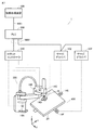
図1は、実施の形態1にかかる生産ラインに備えられるオンライン制御システム1の構成例を示す模式図である。図1を参照して、オンライン制御システム1(以下、単に制御システム1という)は、情報処理装置100、コントローラの一例であるPLC(Programmable Logic Controller)200、ロボット300を制御するロボットコントローラ310およびサーボドライバ13E,13Fを含む。情報処理装置100は、たとえば、PC(Personal Computer)、タブレット端末などの端末装置を含む。サーボドライバ13E,13F(以下、「サーボドライバ13」とも総称する。)は、対応するサーボモータ14E,14Fを駆動する。
FIG. 1 is a schematic diagram showing a configuration example of an
PLC200には、フィールドネットワークNW1を介して情報処理装置100が接続されている。フィールドネットワークNW1には、たとえば、EtherNET(登録商標)が採用される。但し、フィールドネットワークNW1は、EtherNETに限定されず、任意の通信手段が採用され得る。たとえば、コントローラ200および情報処理装置100は、信号線で直接接続されてもよい。情報処理装置100は、ロボット300およびステージ400の機械を制御するための制御プログラムを設計する環境を提供する。情報処理装置100上で設計された制御プログラムは、フィールドネットワークNW1を介してPLC200に送られる。
The
PLC200は、設計された制御プログラムを実行し、実行の結果に従ってロボットコントローラ310またはサーボドライバ13に対してそれぞれ目標値を与えることで、ロボット300およびステージ400を含む対象を制御する。
The
PLC200には、ロボットコントローラ310およびサーボドライバ13が接続されている。PLC200、ロボットコントローラ310およびサーボドライバ13は、フィールドネットワークNW2を介してデイジーチェーンで接続されている。フィールドネットワークNW2には、たとえば、EtherCAT(登録商標)が採用される。但し、フィールドネットワークNW2は、EtherCATに限定されず、任意の通信手段が採用され得る。また、接続態様は、上記のデイジーチェーンに限定されず、ツリー接続またはスター接続のような他の接続態様であってもよい。
A
ロボット300とステージ400は、相互に連携しながらワークWを移動させる。なお、ここでは説明を簡単にするために、ワークWの移動を説明するが、移動に限定されない。例えば、ステージ400上におけるロボット300によるワークWの加工であってもよい。
The
図1では、ロボット300のドライブ装置の一例として、ロボット300に設けられるサーボモータ14A〜140D(以下、「サーボモータ14」とも総称する。)と、サーボモータ14を駆動するロボットコントローラ310を例示する。同様に、ステージ400のドライブ装置の一例として、ステージ400に設けられるサーボモータ14E,14F(以下、「サーボモータ14」とも総称する。)を駆動するサーボドライバ13を例示する。ロボット300は駆動されることにより、その挙動は、直交するX軸,Y軸およびZ軸の3次元空間内で変化する。ステージ400は駆動されることにより、その挙動はロボット300と同じ3次元空間内において規定されるが、X軸およびY軸の平面内において規定される。
In FIG. 1, as an example of the drive device of the
ドライブ装置としては、サーボドライバに限定されることなく、被駆動装置であるモータに応じて、対応するドライブ装置が採用される。たとえば、誘導モータまたは同期モータを駆動する場合には、ドライブ装置として、インバータドライブなどが採用されてもよい。 The drive device is not limited to the servo driver, and a corresponding drive device is adopted according to the motor as the driven device. For example, when driving an induction motor or a synchronous motor, an inverter drive or the like may be adopted as the drive device.
ロボットコントローラ310は、ロボット300のサーボモータ14を駆動する。サーボモータ14の回転軸にはエンコーダ(図示しない)が配置されている。当該エンコーダは、サーボモータ14のフィードバック値として、サーボモータの位置(回転角度)、回転速度、累積回転数などをロボットコントローラ310へ出力する。
The
同様に、サーボドライバ13は、ステージ400のサーボモータ14を駆動する。サーボモータ14の回転軸にはエンコーダ(図示しない)が配置されている。当該エンコーダは、サーボモータ14のフィードバック値として、サーボモータの位置(回転角度)、回転速度、累積回転数などをサーボドライバ13へ出力する。
Similarly, the servo driver 13 drives the servomotor 14 of the
[B.ロボットとステージの制御]
制御システム1におけるロボット300とステージ400の制御について説明する。ロボット300とステージ400は、上記に述べたように、複数の駆動軸により移動可能な可動部を有する。これらの各駆動軸は、サーボモータによって駆動される。具体的には、ロボット300は、サーボモータ14(サーボモータ14A〜14D)が回転することで駆動される複数のアームを有している。サーボモータ14は、それぞれ回転することで、対応する各アームを駆動する。ロボットコントローラ310がサーボモータ14の駆動を制御することで、各アームが3次元に駆動される。このような各アームの駆動により、ロボット300の挙動が実現される。同様に、ステージ400も、サーボモータ14(サーボモータ14E,14F)が回転することでステージ400は移動する。この移動量(移動の向き、距離)は、サーボモータ14の回転量(回転の向き、角度)により決まる。このようなサーボモータ14の駆動により、ステージ400の挙動が実現される。
[B. Robot and stage control]
The control of the
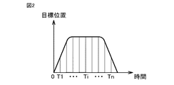
実施の形態1では、ロボット300の各アームは、仮想的な軸が対応付けられ、各軸の位置からロボット300の位置が決まる。図2は、ロボット300の各軸の目標位置を説明する図である。図2を参照して、各軸の目標位置は、ロボット300の挙動が目標となる挙動(以下、目標挙動ともいう)を示すように、時系列に変化する。具体的には、ロボット300の各アームは、時系列に変化する図2の目標位置に従い駆動されることにより、各アームの移動の速度および軌道は、目標に従う速度および軌道となるように変化する。
In the first embodiment, each arm of the
図2に示すような、ロボット300の目標挙動を規定するための目標位置は、PLC200に予め格納されている。ロボットコントローラ310は、PLC200から目標位置を受信し、受信した目標位置に基づき各サーボモータの回転量を決定し、決定した回転量を指定する指令値を、サーボモータ14の各サーボモータに対し出力する。
The target position for defining the target behavior of the
図3は、実施の形態1にかかるロボット300の各アームに相当する軸の3次元仮想空間における位置を算出する過程を模式的に示す図である。図3を参照して、サーボモータ14Aの回転量をαA、サーボモータ14Bの回転量をαB、サーボモータ14Cの回転量をαCおよびサーボモータ14Dの回転量をαDとして示す。サーボモータ回転量(αA、αB、αC、αD)に対し、所定関数を用いて演算を施すことで、サーボモータ回転量(αA、αB、αC、αD)を図3に示すxyzの3次元仮想空間における位置に変換することができる。図3では、例えばワークWをキャッチするアームの軸の3次元仮想空間における位置である3次元座標P(x、y、z)を示すが、他の軸の対応する3次元座標も同様に算出することができる。したがって、各アームの3次元座標P(x、y、z)の時系列の変化によりロボッと300の3次元仮想空間における挙動を示すことができる。
FIG. 3 is a diagram schematically showing a process of calculating the position of the axis corresponding to each arm of the
また、実施の形態1では、説明を簡単にするために、ワークWをキャッチするアームの軸の3次元座標P(x、y、z)を、後述する3次元仮想空間における「干渉」を検出するために用いる。なお、「干渉」の検出には、他の軸の3次元座標P(x、y、z)を用いてもよく、または2つ以上の軸の3次元座標P(x、y、z)の組合せを用いてもよい。 Further, in the first embodiment, in order to simplify the explanation, the three-dimensional coordinates P (x, y, z) of the axis of the arm that catches the work W are detected as "interference" in the three-dimensional virtual space described later. Used to do. The "interference" may be detected by using the three-dimensional coordinates P (x, y, z) of another axis, or the three-dimensional coordinates P (x, y, z) of two or more axes. Combinations may be used.
ステージ400も、ロボット300と同様に、ステージ400の挙動が目標挙動を示すように、ステージ400の移動の速度および軌道は目標位置を示すように時系列に変化する。ステージ400の目標位置は、PLC200に予め格納されている。
Similar to the
サーボドライバ13は、PLC200からの目標位置に基づき各サーボモータの回転量を決定し、決定した回転量を指定する指令値を、サーボモータ14の各サーボモータに対し出力する。このような各サーボモータの回転量に対し、所定関数を用いて演算を施すことで、ステージ400についても、ロボッと300と同じ3次元仮想空間における3次元座標Q(x、y、0)に変換することができる。このような3次元座標Q(x、y、0)の時系列の変化によりステージ400の3次元仮想空間における挙動を示すことができる。
The servo driver 13 determines the rotation amount of each servomotor based on the target position from the
なお、ここでは、ステージ400は平面内の挙動を示すことから、3次元座標Qのz軸は値0で固定としているが、他の固定値であってもよい。
Here, since the
[C.シミュレーション装置の構成]
図4は、実施の形態1にかかる情報処理装置100の構成を概略的に示す図である。図1の制御システム1において、ロボット300およびステージ400が実機としてPLC200により制御される環境をオンラインとした場合、図4の情報処理装置100は、制御システム1をオフラインでシミュレーションする機能を備える。
[C. Simulation device configuration]
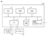
FIG. 4 is a diagram schematically showing the configuration of the
情報処理装置100は、CPU(Central Processing Unit)2とプログラムおよびデータを格納する格納部を備えて、プログラムに従って動作するコンピュータシステムである。格納部は、ROM(Read Only Memory)3、RAM(Random Access Memory)4およびHDD(Hard Disk Drive)5を含む。情報処理装置100は、さらに、通信インタフェース6およびI/O(Input/Output)インタフェース7を含む。また、情報処理装置100は、キーボード37およびディスプレイ38を含む。キーボード37は、ユーザからの情報処理装置100に対する指示を含む入力を受付ける。当該入力を受付けるために、情報処理装置100は、マウス等の他のデバイスを含んでもよい。
The
通信インタフェース6は、情報処理装置100がPLC200を含む外部の機器と通信するためのインタフェースである。
The
I/Oインタフェース7は、情報処理装置100への入力または情報処理装置100からの出力のインタフェースである。図4に示すように、I/Oインタフェース7は、キーボード37とディスプレイ38とに接続され、ユーザがキーボード37に対して入力した情報を受け付ける。また、情報処理装置100の処理結果を、ディスプレイ38へ出力する。ディスプレイ38は、LCD(Liquid Crystal Display)または有機EL(Electro Luminescence)を含み、情報処理装置100から出力される映像信号または画像信号に従う映像または画像を表示する。
The I /
情報処理装置100の格納部は、制御システム1においてロボット300およびステージ400をオンラインで制御するための制御プログラム、制御システム1をシミュレーションするプログラム、ロボット300およびステージ400の挙動をオフラインでエミュレートするエミュレーションプログラム、およびこれらプログラムに関連するデータを格納する。
The storage unit of the
上記のロボット300の制御プログラムは、ロボット300の挙動を制御する複数の命令を含み、同様に、ステージ400の制御プログラムは、ステージ400の挙動を制御する複数の命令を含む。ロボット300のエミュレーションプログラムは、ロボット300の制御プログラムに含まれる上記の複数命令を有している。同様に、ステージ400のエミュレーションプログラムは、ステージ400の制御プログラムに含まれる上記の複数命令を有している。したがって、CPU2によりエミュレーションプログラムが実行されることにより、ロボット300およびステージ400の制御プログラムの複数命令をオフラインで実行されて、エミュレーションプログラムの実行結果は、制御プログラムの実行結果を再現した内容を表すことが可能となる。
The control program of the
情報処理装置100は、後述するオフラインデバッグシステム20により実現される制御プログラムのデバッグ装置としても機能する。オフラインデバッグシステム20が起動されると、情報処理装置100は制御システム1の動作をシミュレートする。このシミュレーションにおいて、情報処理装置100は、ロボット300とステージ400の制御プログラムをエミュレートするためのエミュレーションプログラムを実行する。
The
また、情報処理装置100は、ロボット300とステージ400のエミュレーションプログラムを実行するとき、同一画面において、エミュレーション結果であるロボット300およびステージ400の挙動を描画し、ロボット300およびステージ400の制御プログラムの複数命令を表示するよう、ディスプレイ38を制御する。
Further, when the
これにより、ユーザは、同一画面において、制御プログラムをエミュレートすることにより推定されたロボット300およびステージ400の挙動と、当該挙動を実現しているロボット300およびステージ400の各制御プログラムの命令とを確認することができる。
As a result, the user can see the behavior of the
[D.シミュレーション装置の構成と機能]
図5は、実施の形態1にかかるオフラインデバッグシステム20の機能の構成例を、周辺部と関連づけて説明する図である。図6は、図5のプログラム実行部31の機能の構成例を示す図である。情報処理装置100は、制御システム1をシミュレーションする機能を備える。このシミュレーションの機能は、ロボット300およびステージ400の制御プログラムのデバックを含む編集機能も提供する。
[D. Simulation equipment configuration and functions]
FIG. 5 is a diagram for explaining a configuration example of the function of the
図5を参照して、情報処理装置100は、情報処理装置100の各部を制御する制御部10、キーボード37からのユーザ入力を受付ける入力受付部11、およびオフラインデバッグシステム20を備える。オフラインデバッグシステム20にはディスプレイ38が接続される。ディスプレイ38は、表示制御データに従い表示するべきイメージデータを生成し、イメージデータに従いディスプレイ38を駆動するディスプレイドライバ39を含む。制御部10は、CPU2がシミュレーション制御プログラム21を実行することにより実現される。制御部10は、入力受付部11を介し受付けたユーザの指示に従い、オフラインデバッグシステム20を制御する。
With reference to FIG. 5, the
オフラインデバッグシステム20は、プログラムおよびデータを含んで構成されて、制御部10からの指令に従い、CPU2がプログラムを実行することにより、オフラインデバッグシステム20の機能が実現される。また、オフラインデバッグシステム20の処理結果は、ディスプレイ38が有するディスプレイドライバ39に表示制御データとして出力される。ディスプレイドライバ39は、表示制御データに従うイメージデータに従いディスプレイ38を駆動する。これにより、ディスプレイ38の画面には、情報処理装置100およびオフラインデバッグシステム20の処理の結果を表す画像が表示される。
The
(D-1.オフラインデバッグシステム20の構成)
オフラインデバッグシステム20の構成を説明する。オフラインデバッグシステム20の各部を実現するためのプログラムおよびデータは、ROM3、RAM4およびHDD34を含む格納部に格納されている。
(D-1. Configuration of offline debugging system 20)
The configuration of the
図5を参照して、オフラインデバッグシステム20は、上記に述べたエミュレーションプログラムを実行するプログラム実行部31、描画データを生成する描画データ生成部19、表示制御データに基づきディスプレイドライバ39を制御する表示制御部15、オフラインデバッグシステム20の各部を同期させるための周期的な信号STを生成する周期生成部18、および制御プログラムを編集するプログラム編集部34を備える。
With reference to FIG. 5, the
また、図5を参照して、オフラインデバッグシステム20は、プログラム実行部31に関連してプログラムの実行途中の結果を示す途中データ246を含む。さらに、描画データ生成部19に関連して軌跡データ251,252および画像データ253,254を含む。また、オフラインデバッグシステム20は、プログラム編集部34に関連して、ロボット300の制御プログラムであるロボットプログラム381、ステージ400の制御プログラムであるPLCプログラム371、およびモーション命令DB(データベースの略)361を含む。ロボットプログラム381とPLCプログラム371は格納部12に格納されている。図5の各部および各部を実現するためのプログラムおよびデータは、ROM3、RAM4およびHDD34に格納されている。CPU2は、格納されているプログラムを実行することにより、各部の機能を実現する。
Further, referring to FIG. 5, the
(D−2.プログラム実行部によるエミュレーション)
プログラム実行部31は、PLCプログラム371およびロボットプログラム381をエミュレートするエミュレータプログラムを実行するエンジンに相当する。図6を参照して、プログラム実行部31は、PLC200およびサーボドライバ13の制御プログラムをエミュレートするPLCエミュレータ260、ロボットコントローラ310の制御プログラムをエミュレートするロボットエミュレータ270および共有メモリ12Aを含む。PLCエミュレータ260とロボットエミュレータ270の間のデータ交換は共有メモリ12Aを用いて実現する。共有メモリ12Aを介したPLCエミュレータ260とロボットエミュレータ270の間のデータ交換は、PLC200、サーボドライバ13およびロボットコントローラ310の間のフィールドネットワークNW2のEtherCATを介した通信におけるデータ交換に相当する。
(D-2. Emulation by the program execution unit)
The
PLCエミュレータ260は、ロボット300およびステージ400の挙動を推定するプログラムであって、PLCプログラム371およびロボットプログラム381に含まれた複数の命令を含むエミュレーションプログラムに相当する。これら複数の命令は、PLCプログラム371に含まれたステージ400の挙動を制御するためのモーション命令およびモーション演算命令を含む命令群371Aと、ロボットプログラム381に含まれたロボット300の挙動を制御するための複数のロボット命令を含む命令群381Aを含む。命令群381Aおよび命令群371Aは、四則演算命令のような他の命令も含み得る。後述するように、PLCプログラム371はラダー言語で記載されたプログラムであり、ロボットプログラム381はインタプリタ言語で記載されたプログラムである。したがって、プログラム実行部31は、これら異なる言語のプログラムを実行するためのエミュレータ実行エンジンを備えている。
The PLC emulator 260 is a program that estimates the behavior of the
PLCエミュレータ260のこれら命令群381Aおよび371Aの各命令が、共有メモリ12Aの入力データ144に基づき実行される毎に、サーボモータのための上記に述べた指令値が生成されて、共有メモリ12Aに出力データ145として格納される。
Each time each of the instructions of the
また、ロボットエミュレータ270は、ロボットコントローラ310のプログラムに含まれる命令群を含むエミュレーションプログラムに相当する。この命令群は、共有メモリ12Aの出力データに基づき、ロボット300の目標の軌道を算出するための1以上の軌道演算命令271と、算出された軌道に基づき各軸の指令値を算出する1以上の機構演算命令272を含む。
Further, the
ロボットエミュレータ270の命令群が、共有メモリ12Aの出力データ145に基づき実行されると、ロボット300の各軸のための上記に述べた指令値が生成されて、共有メモリ12Aに入力データ144として格納される。
When the instruction group of the
このように、PLCエミュレータ260とロボットエミュレータ270により生成される指令値は、ロボット300とステージ400の推定された挙動を示すことになる。また、PLCエミュレータ260とロボットエミュレータ270は、それぞれ、他方が算出した指令値に基づき、新たな指令値を算出する。したがって、このように算出される指令値に基づく挙動は、ロボット300とステージ400の動作における相互の関連性を示し得る。
As described above, the command values generated by the
(D−3.描画データの生成)
図5を参照して、描画データ生成部19は、軌跡計算プログラム303および検証プログラム304を含む3D(3-dimensions)視覚化プログラム30を実行する。3D視覚化プログラム30を実行することにより、描画データ生成部19は、軌跡データ251,252と、ロボット300およびステージ400を表す画像データ253および254とに基づいて、ロボット300およびステージ400のエミュレートされた挙動をディスプレイ38画面に描画する描画データ301,401を生成する。ロボット300およびステージ400を表す画像データ253および254は、CAD(computer-aided design)データなどで示される。
(D-3. Generation of drawing data)
With reference to FIG. 5, the drawing data generation unit 19 executes a 3D (3-dimensions)
軌跡計算プログラム303は、図6の共有メモリ12Aの入力データ144に所定関数を用いて演算を施すことで、3次元座標P(x,y,z)および3次元座標Q(x,y,0)を算出し、軌跡データ251,252を取得する。このように軌跡データは、エミュレーションにより推定されたロボット300,ステージ400の3次元仮想空間における挙動を示す情報である。描画データ生成部19は、算出された軌跡データ251とロボット300の画像データ253に従い、ロボット300の挙動を3次元仮想空間内で立体的に描画するための描画データ301を生成し、表示制御部15に出力する。
The
同様に、軌跡計算プログラム303は、軌跡データ252に所定関数を用いて演算を施すことで、時系列の3次元座標Q(x,y,0)を算出し、軌跡データ252として格納する。このように軌跡データ252は、エミュレーションにより推定されたステージ400の挙動を3次元仮想空間内で立体的に描画するため情報である。描画データ生成部19は、算出された軌跡データ252とステージ400の画像データ254に従い、ステージ400の挙動を、ロボット300と同じ3次元仮想空間内で立体的に描画するための描画データ401を生成し、表示制御部15に出力する。
Similarly, the
(D−4.挙動を示す情報の検証)
描画データ生成部19の検証プログラム304は、上記に述べた「検証」を実施するためのプログラムである。描画データ生成部19は、検証プログラム304を実行することにより、軌跡データ251が示すロボット300の3次元仮想空間内における位置を示す位置情報である座標P(x,y,z)と、軌跡データ252が示すステージ400の当該3次元仮想空間内における位置を示す位置情報である座標Q(x,y,0)を検証する。描画データ生成部19は、検証の結果が予め定められた条件を満たすと判定したとき、表示制御部15とプログラム編集部34に通知NTを出力する。
(D-4. Verification of information showing behavior)
The
実施の形態1では、上記の予め定められた条件は、時系列の各時間におけるロボット300の位置を示す座標P(x,y,z)と、当該時間に対応したステージ400の位置を示す座標Q(x,y,0)の両位置間の相対的な関係が、特定位置関係を示すとの条件を含む。特定位置関係は、エミュレータにより推定された3次元仮想空間におけるロボット300の挙動がステージ400の挙動と「干渉」し合うような両者の位置関係を含む。例えば、3次元仮想的空間における座標P(x,y,z)と座標Q(x,y,0)との両者の距離が、例えば閾値以下の距離を含む特定距離であることを含む。または、座標P(x,y,z)と次位の座標P(x,y,z)を結ぶ軌跡が、対応の座標Q(x,y,0)と次位の座標(x,y,0)を結ぶ軌跡と交差したことを含む。なお、特定位置関係は、これらの位置関係に限定されない。
In the first embodiment, the above-mentioned predetermined conditions are the coordinates P (x, y, z) indicating the position of the
(D−5.同期処理)
実施の形態1にかかる周期生成部18は、信号STを生成する仮想時刻生成プログラム29を実行する。周期生成部18は、生成された信号STを他の各部に出力する。各部は、周期生成部18から信号STが出力される周期に同期して処理またはプログラムを実行する。これにより、オフラインデバッグシステム20の各部の処理またはプログラムは、信号STの周期で、または当該周期に同期して実行される。信号STの周期は、図1の制御システム1のフィールドネットワークNW2の通信周期(以下、「制御周期」ともいう。)に相当する。なお、フィールドネットワークNW2の通信周期は変更可能であり、信号STの周期は変更後のフィールドネットワークNW2の通信周期に同期するように変更され得る。
(D-5. Synchronous processing)
The cycle generation unit 18 according to the first embodiment executes a virtual
図7は、実施の形態1にかかる仮想時刻によりエミュレータの同期を説明する図である。図7を参照して、周期生成部18は、CPU2が有するタイマ(図示せず)の出力に基づき、例えば1msecの周期を有した信号STを生成し出力する。プログラム実行部31は、信号STの共通の周期に従い、PLCエミュレータ260とロボットエミュレータ270とに指令値の計算を開始させる。これにより、PLCエミュレータ260とロボットエミュレータ270は信号STが示す共通の周期に同期して周期的に実行される。計算を開始すると、PLCエミュレータ260は入力データ144に基づき指令値を算出し、またロボットエミュレータ270は出力データ145に基づき指令値を算出する。プログラム実行部31は、周期毎に、算出された指令値を共有メモリ12Aに出力(書込)する。
FIG. 7 is a diagram illustrating synchronization of the emulator according to the virtual time according to the first embodiment. With reference to FIG. 7, the cycle generation unit 18 generates and outputs a signal ST having a period of, for example, 1 msec, based on the output of a timer (not shown) included in the
これにより、PLCエミュレータ260とロボットエミュレータ270の両者において指令値の演算に要する計算時間にバラツキがあっても、言い換えるとPLCプログラム371とロボットプログラム381の間で計算時間が異なっても、PLCエミュレータ260とロボットエミュレータ270は、それぞれ、算出した指令値を出力するタイミングを制御周期に合わせることができる。したがって、PLCエミュレータ260とロボットエミュレータ270の両者は、各制御周期において、直前の制御周期で算出された指令値を用いて新たな指令値を算出することが可能になる。
As a result, even if the calculation time required for calculating the command value varies between the
上記のPLCプログラム371とロボットプログラム381の間で計算時間のバラツキは、例えばPLCプログラム371とロボットプログラム381のプログラム言語の種類に基づく。例えば、実施の形態1では、後述するように、ロボットプログラム381は逐次実行型の言語で記載されて、PLCプログラム371はサイクリック実行型言語で記載されており、両プログラム間では、1命令の実行完了に要する時間が相違する。
The variation in calculation time between the
(D−6.プログラム編集)
プログラム編集部34は、PLCプログラムエディタ32およびロボットプログラムエディタ33および命令抽出部36を含む。PLCプログラムエディタ32およびロボットプログラムエディタ33は、それぞれ、ロボットプログラム381およびPLCプログラム371を、制御部10が入力受付部11を介して受付けたユーザ入力に従い編集(変更、追加、削除など)するエディタプログラムに相当する。
(D-6. Program editing)
The
また、プログラム編集部34は、格納部からロボットプログラム381とPLCプログラム371を読出し、読出された各プログラムを表示制御部15に出力する。実施の形態1では、ロボットプログラム381とPLCプログラム371は、ソースプログラムであり、例えばテキストデータで表示される。
Further, the
命令抽出部36は、モーション命令DB361を作成する。
また、プログラム編集部34は、描画データ生成部19から上記の検証の結果を示す通知NTを入力すると、変更指令R1を表示制御部15に出力する。変更指令R1は、通知NTを入力した時点で抽出された命令(実行中の命令)の表示態様の変更を行わせる指令を示す。
The
Further, when the
(D−7.表示制御部15の処理)
表示制御部15は、描画表示制御部16およびプログラム表示制御部17を含む。描画表示制御部16は、描画データ生成部19からのロボット300の挙動を示す描画データ301およびステージ400の挙動を示す描画データ401から、ロボット300,ステージ400の挙動を示す画像を表示させる表示制御データを生成し、ディスプレイドライバ39に出力する。また、これと同時に、プログラム表示制御部17は、ディスプレイ38に、プログラム編集部34からのロボットプログラム381およびPLCプログラム371のデータが示す複数命令を表示させる表示制御データを生成し、ディスプレイドライバ39に出力する。
(D-7. Processing of display control unit 15)
The
これにより、ディスプレイ38の同一画面には、ロボット300の挙動を描画する画像と、ステージ400の挙動を描画する画像と、ロボットプログラム381の複数命令を表示する画像と、PLCプログラム371の複数命令を表示する画像とが同時に表示される。
As a result, on the same screen of the
さらに、「干渉」が検出されたときは、ディスプレイ38の同一画面には、「干渉」の検出を表す画像が表示される。したがって、情報処理装置100はディスプレイ38に表示する画像により、エミュレートにより推定されるロボット300の挙動とステージ400の挙動が「干渉」しあうか否かと、「干渉」した時期(タイミング)を報知することが可能となる。
Further, when "interference" is detected, an image showing the detection of "interference" is displayed on the same screen of the
また、プログラム表示制御部17の表示態様変更部35は、プログラム編集部34からの変更指令R1を入力したとき、実行中の命令の表示態様の変更を行わせる表示制御データを出力する。
Further, when the change command R1 from the
これにより、情報処理装置100は、エミュレートされているロボットプログラム381およびPLCプログラム371のそれぞれの複数命令を、PLCエミュレータ260により実行中の命令を指示しながら表示することができる。また、「干渉」が検出されたときに実行中の命令を、他の命令とは表示態様を異ならせて、表示することができる。したがって、ユーザが、ロボットプログラム381およびPLCプログラム371の命令のうちから、「干渉」の要因となり得る命令を特定するのを支援することができる。
As a result, the
(D−8.「干渉」を検出した場合の処理の停止)
実施の形態1では、「干渉」が検出されたとき、描画データ生成部19は通知NTを各部に出力する。
(D-8. Stop processing when "interference" is detected)
In the first embodiment, when "interference" is detected, the drawing data generation unit 19 outputs a notification NT to each unit.
プログラム実行部31は、通知NTを入力したとき、エミュレータの実行を停止する。エミュレータの実行停止により、軌跡データ251,252の更新は停止し、ディスプレイ38におけるロボット300およびステージ400の挙動を示す画像の更新は停止する。また、エミュレータの実行停止により、実行中命令の新たな抽出も停止する。
The
また、通知NTを入力したとき、表示制御部15は、ディスプレイ38の表示を停止させる。これにより、たとえ、エミュレータの実行が停止しないとしても、ディスプレイ38の画面を、「干渉」が検出された時点の静止画の画面とすることができる。
Further, when the notification NT is input, the
また、通知NTを入力したとき、周期生成部18は、仮想時刻生成プログラム29の実行を停止する。これにより、オフラインデバッグシステム20の各部への信号STの出力は停止し、各部は、信号STに同期した処理を停止する。
Further, when the notification NT is input, the cycle generation unit 18 stops the execution of the virtual
なお、「干渉」を検出した場合の処理の停止は、上記に述べた停止の処理の2種類以上を組合わせて実施してもよい。 The processing may be stopped when "interference" is detected by combining two or more types of the stopping processing described above.
[E.モーション命令DBの作成]
図8は、実施の形態1にかかるモーション命令の一例を説明する図である。図9は、実施の形態1にかかるモーション命令DB361の概要を示す図である。実施の形態1では、例えば、ロボットプログラム381はインタプリタ言語のような逐次実行型の言語で記載されて、PLCプログラム371はラダー言語またはストラクチャードテキスト言語のようなサイクリック実行型言語で記載される。なお、各プログラムを記載する言語は、これらに限定されない。
[E. Creation of motion command DB]
FIG. 8 is a diagram illustrating an example of a motion command according to the first embodiment. FIG. 9 is a diagram showing an outline of the
ロボットプログラム381とPLCプログラム371は、言語の特性により、命令の1ステップを実行するのに要する時間は異なる。PLCエミュレータ260は、逐次実行型のロボットプログラム381の命令群381Aを、先頭から順番に命令を実行する。この場合、信号STが示す1周期で1命令を実行し、1命令の実行が完了するまでは、次の命令を実行せず、完了したとき信号STの次の周期で次の命令を実行する。したがって、命令群381Aのうち実行中の命令および「干渉」が検出されたときに実行されていた命令を容易に特定することができる。
The
これに対し、PLCエミュレータ260は、サイクリック実行型のPLCプログラム371の複数命令を、信号STの1周期でプログラムの先頭、すなわち複数命令の先頭から終わりまで実行するが、各命令は、1〜N(≧2)の周期で実行を完了する。したがって、「干渉」が検出された場合に、PLCエミュレータ260が命令群381Aの実行を停止した場合、常に、命令群381Aの先頭命令で停止することとなる。したがって、命令群381Aのうち、「干渉」が検出されたときに実行中の命令を特定するための処理が必要となる。実施の形態1では、命令抽出部36により、当該処理のためにモーション命令DB361の作成が実施される。
On the other hand, the
図8を参照して、PLCプログラム371に含まれるモーション命令は、PLC機構名B1、命令の宣言名B2、当該モーション命令の実行状態を示す変数B3およびB4を含む。変数B3は、モーション命令が実行開始されているか否かを示す変数「Execute」に対応し、変数B4は、モーション命令の実行が完了しているか否かを示す変数「Done」に対応する。
With reference to FIG. 8, the motion instruction included in the
命令抽出部36は、モーション命令DB361を作成する。具体的には、命令抽出部36は、PLCプログラム371を検索し複数のモーション命令を抽出する。命令抽出部36は、抽出された各モーション命令について、図9に示すように、宣言名B2、Location(ロケーション)情報362、および変数「Execute」と変数「Done」の値363を関連付けて有するレコードRを生成し、生成したレコードRをモーション命令DB361に格納する。
The
レコードRのLocation情報362は、PLCプログラム371における当該モーション命令の相対的な位置を一意的に示す情報であって、例えばURI(Uniform Resource Identifier)を含む。実施の形態1では、PLCプログラム371がプログラム表示制御部17を介してディスプレイ38に表示されるとき、各モーション命令のディスプレイ38の画面における位置は、Location情報362に基づき特定することができる。
The
[F.PLCエミュレータで実行中の命令の検出処理]
実施の形態1では、PLCプログラム371およびロボットプログラム381の命令のうち、PLCエミュレータ260で実行中の命令を検出し、検出の結果を表示する。
[F. Detection processing of instructions being executed by the PLC emulator]
In the first embodiment, among the instructions of the
PLCプログラム371に関しては、この検出のために、レコードRの変数「Execute」と変数「Done」の値363が用いられる。具体的には、レコードRが作成されたとき、値363には初期値(例えば、Null)が設定される。プログラム編集部34は、各レコードRの変数「Execute」と変数「Done」の値363の書込み、および読出しを実施する。具体的には、プログラム編集部34のPLCプログラムエディタ32は、信号STの周期毎に、途中データ246から、各モーション命令の変数「Execute」と変数「Done」の値を検出し、検出された値を、モーション命令DB361の当該モーション命令に対応のレコードRの値363を書込む。この途中データ246には、PLCエミュレータ260による命令群371Aおよび381Aの実行の結果が信号STの周期に同期して書込まれる。途中データ246が示す実行の結果は、各モーション命令の変数「Execute」と変数「Done」の値を含む。
For the
PLCエミュレータ260は、各モーション命令の変数「Execute」と変数「Done」の値363を、当該モーション命令が実行開始されたとき、‘true’と‘false’に設定して、その後、当該モーション命令の実行が完了すると変数「Execute」と変数「Done」の値363を両方とも‘true’に設定する。したがって、途中データ246から、変数「Execute」と変数「Done」の値363が‘true’と‘false’を示すモーション命令を抽出することにより、実行中(実行は開始されたが、未だ完了していない)のモーション命令を判断することができる。
The PLC emulator 260 sets the
PLCプログラムエディタ32は、制御周期に基づく信号STが示す周期に同期して、途中データ246が示す各モーション命令の変数「Execute」および変数「Done」の値を、モーション命令DB361における当該モーション命令に対応の値363に書込む。これにより、モーション命令DB361の各モーション命令の変数「Execute」および変数「Done」の値363を、信号STが示す周期毎に、最新の値を示すように、更新することができる。例えば、図9のモーション命令DB361において、矢印で示すモーション命令は、実行中の命令を示す。
The
また、ロボットプログラム381で実行中の命令を検出するために、PLCエミュレータ260は、信号STの周期毎にカウントアップするカウンタを有している。具体的には、PLCエミュレータ260は、命令群381Aの先頭の命令から、信号STの周期毎に、1命令ずつ実行するとともに、カウンタをカウントアップする。したがって、ロボットプログラムエディタ33は、このカウンタの値から、ロボットプログラム381の命令のうち、PLCエミュレータ260で実行中の命令を特定することができる。なお、ロボットプログラム381の命令のうち、PLCエミュレータ260で実行中の命令を特定する方法は、このカウンタを用いる方法に限定されない。
Further, in order to detect an instruction being executed by the
[G.表示画面の例示]
図10と図11は、実施の形態1にかかる表示画面の一例を示す図である。オフラインデバッグシステム20は、図10と図11に示す画像をディスプレイ38に表示する。具体的には、図10の画面は、PLCプログラム371の命令を表示する領域E1、ロボットプログラム381の命令を表示する領域E2、画像を描画する領域E3、および領域E4を含む。領域E3は、3次元仮想空間におけるロボット300およびステージ400の推定された挙動を示す画像OB1,OB2が表示される。領域E4は、エミュレーション対象となるPLCプログラムおよびロボットプログラムの組のユーザによる選択を受付けるための領域である。具体的には、領域E4には、エミュレーション候補であるPLCプログラムおよびロボットプログラムの名称の一覧が表示される。ユーザは、一覧からエミュレーション対象となるPLCプログラムおよびロボットプログラムの組を指定することで、選択することができる。プログラム実行部31は、選択されたプログラムについて、エミュレーションを実行する。
[G. Display screen example]
10 and 11 are diagrams showing an example of the display screen according to the first embodiment. The
なお、上記に述べたPLCプログラムの選択は、領域E4を用いた方法に限定されない。例えば、ユーザは、オフラインデバッグシステム20がディスプレイ38を介して表示する「タスク設定画面」から、PLCプログラムを選択的に指定することができる。また、上記に述べたロボットプログラムの選択も、領域E4を用いた方法に限定されない。PLCプログラムの命令からロボットプログラムを呼び出すことで選択することができる。
The selection of the PLC program described above is not limited to the method using the region E4. For example, the user can selectively specify the PLC program from the "task setting screen" displayed by the
制御部10は、入力受付部11を介して受付けた上記の選択内容をプログラム編集部34に出力する。プログラム編集部34は、制御部10からの選択内容に基づき、ユーザが指定したロボットプログラム381とPLCプログラム371を格納部12から読出し、表示制御部15に出力する。プログラム表示制御部17は、プログラム編集部34からのロボットプログラム381とPLCプログラム371に基づく表示制御データを生成し、ディスプレイ38に出力する。ディスプレイドライバ39は、表示制御データに基づきロボットプログラム381とPLCプログラム371を、それぞれ領域E1と領域E2に表示する。この領域E1と領域E2には、ロボットプログラム381とPLCプログラム371のソースコードのようなユーザが編集可能なコードが表示される。
The
PLCエミュレータ260により、ロボットプログラム381とPLCプログラム371をエミュレーション中に、「干渉」が検出された場合の表示例が図11に示される。図11の画面では、領域E3の画像に関連付けて「干渉」が検出された旨を示す予め定められた色のポリゴンPNが表示される。このポリゴンPNは、画像の干渉が検出された部分において表示され得る。「干渉」が検出された旨を示す画像に関連付けて表示されるマークは、上記に述べたポリゴンPNに限定されない。また、領域E1のPLCプログラム371のモーション命令のうち「干渉」が検出されたときに実行中と判断された命令CM1は、他のモーション命令とは異なる予め定められた表示態様に変更されている。同様に、領域E2のロボットプログラム381の命令のうち「干渉」が検出されたときに実行中と判断された命令CM2も他の命令とは異なる予め定められた表示態様に変更されている。
FIG. 11 shows a display example when "interference" is detected while emulating the
予め定められた表示態様は、例えば、反転表示、点滅表示、当該命令を指示するマーカの表示などを含む。また、図11に示すように、「干渉」が検出されたときに実行中と判断された命令CM1および命令CM2の内容または種類を示す情報(円弧補間命令、直線補間命令など)を表示してもよい。図11の画面から、「干渉」の要因となり得る命令、すなわちデバッグの候補となる命令の情報をユーザに提供することができる。 The predetermined display mode includes, for example, a reverse display, a blinking display, a display of a marker instructing the command, and the like. Further, as shown in FIG. 11, information (arc interpolation command, linear interpolation command, etc.) indicating the content or type of the instruction CM1 and the instruction CM2 determined to be executed when "interference" is detected is displayed. May be good. From the screen of FIG. 11, it is possible to provide the user with information on an instruction that can cause "interference", that is, an instruction that is a candidate for debugging.
ディスプレイ38の画面における領域E1〜E4は、図10または図11の配置に限定されない。また、この配置は、ユーザの操作内容に従い変更することが可能である。
Areas E1 to E4 on the screen of the
[H.オフラインデバッグシステム20の処理]
図12と図13は、実施の形態1にかかるオフラインデバッグシステム20の処理を説明する図である。図12と図13では、オフラインデバッグシステム20の処理が、各部間の信号の入出力関係を示すタイミングチャートと関連付けて示される。
[H. Offline debugging
12 and 13 are diagrams illustrating the processing of the
図12を参照して、制御部10のシミュレーション制御プログラム21は、入力受付部11を介してユーザから起動指令を受付けると(ステップT1)、起動し、モーション命令DBを作成するための指令を出力する。
With reference to FIG. 12, when the
命令抽出部36は、シミュレーション制御プログラム21からの指令に従い、上記に述べたモーション命令DB361に作成する(ステップT2)。具体的には、命令抽出部36は、格納部12のPLCプログラム371からモーション命令を検索し、検索された各モーション命令のlocation情報を有するレコードRを生成し、生成されたレコードRを有するモーション命令DB361を作成する。
The
制御部10のシミュレーション制御プログラム21は、周期生成部18に起動指令を出力する(ステップT3)。周期生成部18は起動指令に従い仮想時刻生成プログラム29を起動する。仮想時刻生成プログラム29は起動されると、信号STの出力を開始するとともに、PLCエミュレータ260とロボットエミュレータ270に起動指令を出力する(ステップT4,T5)。
The
プログラム実行部31は、起動指令に従いPLCエミュレータ260とロボットエミュレータ270を起動し、指令値を算出する指令値演算処理を、信号STの周期で繰返(Loop)す処理SB1を実施する。処理SB1は、図12に示す処理SB2、SB3およびSB4を含む。処理SB1は、1制御周期に1回実行される。
The
図13を参照して、処理SB1では、まず、制御部10のシミュレーション制御プログラム21は、プログラム実行部31のエミュレータが一時停止しているかを判断する。制御部10は、プログラム実行部31のエミュレータの実行が停止していると判断したとき、以降の処理SB2をスキップする。これにより、処理SB1は終了し、処理SBも終了する。
With reference to FIG. 13, in the process SB1, first, the
一方、制御部10のシミュレーション制御プログラム21は、プログラム実行部31によるエミュレータの実行が一時停止していない、すなわち実行中であると判断したとき、処理SB2を開始する。
On the other hand, the
処理SB2では、まず、周期生成部18の仮想時刻生成プログラム29は、演算指令をプログラム実行部31のPLCエミュレータ260とロボットエミュレータ270に出力する。プログラム実行部31のPLCエミュレータ260とロボットエミュレータ270は、演算指令に従い各軸の指令値を算出し、入力データ144として共有メモリ12Aに格納する(ステップS1)。周期生成部18の仮想時刻生成プログラム29は、プログラム実行部31による演算が完了すると、次の信号STの周期まで待機する(ステップS2)。
In the process SB2, first, the virtual
プログラム実行部31は、PLCエミュレータ260による実行途中の結果を示す途中データ246を、信号STの周期毎に取得し格納する。
The
処理SB3では、描画データ生成部19は3D視覚化プログラム30により、描画の更新タイミングであるかを判断する。描画の更新タイミングであると判断しないときは、処理SB3をスキップする。これにより、今回の処理SBは終了する。
In the process SB3, the drawing data generation unit 19 determines whether or not it is the drawing update timing by the
ここで、実施の形態1では、「干渉」が発生したタイミングを正確に検出するために、描画を更新する周期は制御周期に一致する。したがって、処理SB3は、各制御周期においてスキップされることなく実施される。なお、処理SB3を、制御周期のN(≧2)周期毎に実施する場合は、処理SB3がスキップされる周期が生じ得て、その結果、全ての周期で処理SB3を実施する場合に比較して、描画に関する負荷を軽減することができる。 Here, in the first embodiment, the cycle for updating the drawing coincides with the control cycle in order to accurately detect the timing at which "interference" occurs. Therefore, the process SB3 is performed without being skipped in each control cycle. When the processing SB3 is executed every N (≧ 2) period of the control cycle, there may be a cycle in which the processing SB3 is skipped, and as a result, the processing SB3 is compared with the case where the processing SB3 is executed in all the cycles. Therefore, the load related to drawing can be reduced.
描画データ生成部19は、描画の更新タイミングであると判断したとき、PLCエミュレータ260とロボットエミュレータ270により算出された各軸の指令値を取得する(ステップS3)。具体的には、描画データ生成部19は3D視覚化プログラム30により、共有メモリ12Aを検索し、共有メモリ12Aから指令値を取得する。描画データ生成部19は、3D視覚化プログラム30により、指令値から軌跡データ251,252を算出し、算出された軌跡データ251,252と画像データ253,254とから描画データ301,401を生成する。描画データ生成部19は、ディスプレイ38の領域E3の画像を更新するために、表示制御部15に描画データ301,401を出力する(ステップS4)。
When the drawing data generation unit 19 determines that it is the drawing update timing, it acquires the command value of each axis calculated by the
描画データ生成部19は、ディスプレイ38の領域E3の描画内容を更新するとき、上記に述べた検証を実施して、「干渉」が有るか否か判断する(ステップS5)。
When updating the drawing content of the area E3 of the
描画データ生成部19は、「干渉」が有ると判断しないときは、次の処理SB4をスキップして、今回の処理SBを終了する。一方、描画データ生成部19は、「干渉」が有ると判断したときは、通知NTを出力し、次の処理SB4を実行する。 When the drawing data generation unit 19 does not determine that there is "interference", the drawing data generation unit 19 skips the next processing SB4 and ends the current processing SB. On the other hand, when the drawing data generation unit 19 determines that there is "interference", it outputs a notification NT and executes the next process SB4.
処理SB4では、描画データ生成部19は、通知NTに従い3D視覚化プログラム30により、周期生成部18に一時停止を通知する(ステップS6)。周期生成部18は、一時停止通知を受付けると、仮想時刻生成プログラム29の実行を停止する。これにより、信号STの出力は停止し、プログラム実行部31のエミュレータも一時停止する。
In the process SB4, the drawing data generation unit 19 notifies the cycle generation unit 18 of the pause by the
描画データ生成部19は、実行中の命令、すなわち「干渉」が検出されたときに実行中の命令を表示する表示指令をプログラム編集部34に出力する。プログラム編集部34は、表示指令に従い、実行中の命令を検出し、検出された命令を表示するための変更指令R1を表示制御部15に出力する(ステップS7,S8)。
The drawing data generation unit 19 outputs a display command for displaying the command being executed, that is, a display command for displaying the command being executed when "interference" is detected, to the
具体的には、プログラム編集部34のPLCプログラムエディタ32は、描画データ生成部19からの表示指令に基づき、モーション命令DB361から変数「Execute」および変数「Done」の値363が(‘true’,‘false’)を示すレコードRを検索し、検索されたレコードRのLocation情報362を読出す。また、プログラム編集部34のロボットプログラムエディタ33は、描画データ生成部19からの表示指令に基づき、上記に述べたカウンタの値を取得する。これにより、PLCプログラム371およびロボットプログラム381の命令のうちから、「干渉」が検出されたときにPLCエミュレータ260で実行中の命令を特定する情報が取得される。
Specifically, in the
プログラム編集部34は、「干渉」が検出されたときにPLCエミュレータ260で実行中の命令を特定する情報(「Location情報362およびカウンタ値を含む情報)から、変更指令R1を生成し、プログラム表示制御部17に出力する。
The
プログラム表示制御部17の表示態様変更部35は、変更指令R1に基づく表示制御データを生成し、出力する。ディスプレイドライバ39は、表示制御部15からの表示制御データに従うイメージデータを生成し、イメージデータに基づきディスプレイ38を駆動することで、表示制御データに従う画像をディスプレイ38に表示させる。これにより、ディスプレイ38の領域E1とE2で表示中のロボットプログラム381およびPLCプログラム371それぞれの複数命令のうち、「干渉」が検出されたときに実行中の命令CM1,CM2の表示態様は、他の命令の態様とは異なるように変更される(図11参照)。
The display
また、「干渉」が検出されたとき、描画表示制御部16は、上記に述べた予め定められた色のポリゴンPNの表示制御データを生成し出力する。ディスプレイドライバ39は、描画表示制御部16からの表示制御データに従い、ディスプレイ38の画面の領域E3のロボットプログラム381およびPLCプログラム371の挙動を示す画像に関連付けて予め定められた色のポリゴンPNを表示する(図11参照)。
When "interference" is detected, the drawing
このように図11の画面では、「干渉」が検出された時点で、エミュレータで実行中の命令CM1,CM2の表示態様は変更される。ユーザは、命令CM1とCM2を、ロボットプログラム381およびPLCプログラム371をデバッグするための支援情報として利用することができる。ユーザは、命令CM1とCM2の情報に基づき、キーボード37を操作して、領域E1とE2で表示中のロボットプログラム381およびPLCプログラム371の編集(変更、追加、削除など)指示を入力する。制御部10は、入力受付部11を介して編集指示を受付ける。プログラム編集部34は、制御部10からの編集指示に基づき、ロボットプログラム381およびPLCプログラム371を編集する。これにより、格納部12のロボットプログラム381およびPLCプログラム371は、「干渉」の要因となるバグが解消されるように編集(デバッグ)され得る。
As described above, on the screen of FIG. 11, when "interference" is detected, the display mode of the instructions CM1 and CM2 being executed by the emulator is changed. The user can use the instructions CM1 and CM2 as support information for debugging the
上記のようにデバッグされたロボットプログラム381およびPLCプログラム371をプログラム実行部31でエミュレートすることで、ユーザは、ディスプレイ38の画面から「干渉」が解消されたことを確認できる。
By emulating the
[I.他の表示例]
図14、図15および図16は、実施の形態1にかかる表示画面の他の例を示す図である。図14、図15および図16では、ロボットと、スライダの挙動をエミュレートした場合の画面を示す。図14、図15および図16のロボットは、図10,図11に示されたロボット300とは異なるタイプであり、またステージ400に代えてスライダが示されるが、オフラインデバッグシステム20の処理内容は、上記に説明したものと同様であるから、この処理内容は繰返さない。
[I. Other display examples]
14, 15 and 16 are views showing another example of the display screen according to the first embodiment. 14, 15 and 16 show screens when the robot and the behavior of the slider are emulated. The robots of FIGS. 14, 15 and 16 are of a different type from the
図14では、入力受付部11がユーザから受付けた入力内容に従い、制御部10は、領域E4の一覧からロボットプログラム381とPLCプログラム371の両方が選択された場合を示す。図14では、制御部10からの指示に従い、周期生成部18は、PLCエミュレータ260とロボットエミュレータ270とを起動する(図12のステップT6,T7を参照)。
FIG. 14 shows a case where both the
図14では、領域E4からPLCプログラム371とロボットプログラム381の両方が選択されたが、図15は、領域E4の一覧からロボットプログラム381のみが選択された場合を示す。図15に示すように、ディスプレイ38の画面は、ロボットプログラム381を表示する領域E2とロボットとスライダの挙動を示す画像を表示する領域E3を含み、PLCプログラム371を表示する領域E1は省略されている。この場合、PLCプログラム371は非表示であっても、PLCエミュレータ260はロボット命令の命令群381AとPLCプログラム371の命令群371Aとを実行する。領域E3では、スライダの挙動とロボットの挙動を描画する画像が表示されて、「干渉」が検出されると、上記に述べたポリゴンPN、命令CM2が表示される。
In FIG. 14, both the
なお、図15では、PLCエミュレータ260はロボット命令の命令群381Aのみ実行することも可能である。その場合は、領域E3では、スライダの静止画に関連付けてロボットの挙動を描画する画像が表示される。例えば、スライダの静止画の座標と描画されるロボットの座標との両位置間の相対的な関係が、特定位置関係を示すとの条件が満たされるとき「干渉」が検出されて、検出の結果である上記に述べたポリゴンPN、命令CM2が表示される。
In FIG. 15, the PLC emulator 260 can execute only the
図16は、領域E4の一覧からPLCプログラム371のみが選択された場合を示す。図16に示すように、ディスプレイ38の画面は、PLCプログラム371を表示する領域E1とロボットとスライダの挙動を示す画像を表示する領域E3を含み、ロボットプログラム381を表示する領域E2は省略されている。この場合、ロボットプログラム381は非表示であっても、PLCエミュレータ260はPLCプログラムの命令群381AとPLCプログラム371の命令群371Aとを実行する。領域E3では、スライダの挙動とロボットの挙動を描画する画像が表示されて、「干渉」が検出されると、上記に述べたポリゴンPN、命令CM1が表示される。
FIG. 16 shows a case where only the
なお、図16では、PLCエミュレータ260はPLCプログラムの命令群371Aのみ実行することも可能である。この場合は、例えばロボットの静止画の座標と挙動が描画されるスライダの座標との両位置間の相対的な関係が、特定位置関係を示すとの条件が満たされるとき「干渉」が検出されて、検出の結果である上記に述べたポリゴンPN、命令CM1が表示される。
In FIG. 16, the PLC emulator 260 can execute only the
<実施の形態2>
図5には、情報処理装置100のCPU2がプログラムを実行することで必要な機能が提供される構成例を示したが、これらの提供される機能の一部または全部を、専用のハードウェア回路(たとえば、ASIC(Application Specific Integrated Circuit)またはFPGA(Field-Programmable Gate Array)など)を用いて実装してもよい。あるいは、情報処理装置100の主要部を、汎用的なアーキテクチャに従うハードウェアを用いて実現してもよい。この場合には、仮想化技術を用いて、用途の異なる複数のOS(Operating System)を並列的に実行させるとともに、各OS上で必要なアプリケーションを実行させるようにしてもよい。
<
FIG. 5 shows a configuration example in which the
また、情報処理装置100は、CPU2のような複数のプロセッサを備える場合は、図5に示す各部は、複数のプロセッサにより実行することが可能である。また、CPU2が複数のコアを含む場合は、図5に示す各部は、CPU2内の複数のコアにより実行することが可能である。
Further, when the
<実施の形態の利点>
上記に述べた各実施の形態によれば、オフラインデバッグシステム20は、PLCエミュレータ260およびロボットエミュレータ270の実行により推定される実機の挙動と、PLCプログラム371およびロボットプログラム381の各命令を同一画面で同時に表示させる。したがって、推定される実機の挙動を表す画像により、同一画面で表示中のPLCプログラム371およびロボットプログラム381をデバッグなど編集するための支援情報を提供することが可能となる。
<Advantages of the embodiment>
According to each of the above-described embodiments, the
また、PLCプログラム371およびロボットプログラム381により制御される対象の挙動の推定は、PLCプログラム371およびロボットプログラム381の命令を実行するエミュレータ(PLCエミュレータ260およびロボットエミュレータ270)によりなされるので、より正確に対象の挙動を再現(描画)することができる。
Further, the behavior of the object controlled by the
また、推定される挙動において「干渉」が検出されたとき、領域E1と領域E2で表示中のPLCプログラム371およびロボットプログラム381の命令のうち、その時点で、エミュレータで実行中の命令CM1,CM2は表示態様を変更して表示される。したがって、「干渉」の原因となる命令に関する情報を提供することができる。また、領域E1と領域E2におけるPLCプログラム371およびロボットプログラム381において、デバッグするための的確な支援情報(プログラムの修正箇所など)を提供することができる。これにより、デバッグを含むロボット300とステージ400の制御プログラムの作成にかかる作業量と作業時間を削減することができる。
Further, when "interference" is detected in the estimated behavior, among the instructions of the
また、上記に述べたデバッグ支援情報の提供は、実機がなくても「干渉」のタイミングを正確に再現できることによって実現される。これにより、実機がなくても正確なプログラムの作成、デバッグを実施できる環境を提供することが可能となる。 In addition, the above-mentioned provision of debug support information is realized by being able to accurately reproduce the timing of "interference" without an actual machine. This makes it possible to provide an environment in which accurate programs can be created and debugged without an actual machine.
また、実機がなくても正確なプログラムを作成できる環境が提供されることから、制御システム1におけるタクトタイムを正確に見積もることも可能となる。また、PLCプログラム371およびロボットプログラム381の実機によるチューニング工数を削減することもできる。
Further, since an environment in which an accurate program can be created without an actual machine is provided, it is possible to accurately estimate the takt time in the
今回開示された実施の形態は全ての点で例示であって制限的なものではないと考えられるべきである。本発明の範囲は上記した説明ではなくて特許請求の範囲によって示され、特許請求の範囲と均等の意味および範囲内での全ての変更が含まれることが意図される。 It should be considered that the embodiments disclosed this time are exemplary in all respects and not restrictive. The scope of the present invention is shown by the scope of claims rather than the above description, and it is intended to include all modifications within the meaning and scope equivalent to the scope of claims.
1 オンライン制御システム、10 制御部、11 入力受付部、12 格納部、12A 共有メモリ、13,13E,13F サーボドライバ、14,14A,14B,14C,14D,14E,14F,140D サーボモータ、15 表示制御部、16 描画表示制御部、17 プログラム表示制御部、18 周期生成部、19 描画データ生成部、20 オフラインデバッグシステム、21 シミュレーション制御プログラム、29 仮想時刻生成プログラム、30 視覚化プログラム、31 プログラム実行部、32 PLCプログラムエディタ、33 ロボットプログラムエディタ、34 プログラム編集部、35 表示態様変更部、36 命令抽出部、38 ディスプレイ、39 ディスプレイドライバ、100 情報処理装置、144 入力データ、145 出力データ、246 途中データ、251,252 軌跡データ、253,254 画像データ、260 PLCエミュレータ、270 ロボットエミュレータ、300 ロボット、301,401 描画データ、303 軌跡計算プログラム、304 検証プログラム、310 ロボットコントローラ、371 PLCプログラム、371A,381A 命令群、381 ロボットプログラム、400 ステージ、CM1,CM2 命令、PN ポリゴン、R1 変更指令。 1 Online control system, 10 Control unit, 11 Input reception unit, 12 Storage unit, 12A shared memory, 13, 13E, 13F servo driver, 14, 14A, 14B, 14C, 14D, 14E, 14F, 140D servo motor, 15 display Control unit, 16 drawing display control unit, 17 program display control unit, 18 cycle generation unit, 19 drawing data generation unit, 20 offline debug system, 21 simulation control program, 29 virtual time generation program, 30 visualization program, 31 program execution Unit, 32 PLC program editor, 33 robot program editor, 34 program editor, 35 display mode change unit, 36 instruction extractor, 38 display, 39 display driver, 100 information processing device, 144 input data, 145 output data, 246 intermediate Data, 251,252 trajectory data, 253, 254 image data, 260 PLC emulator, 270 robot emulator, 300 robot, 301, 401 drawing data, 303 trajectory calculation program, 304 verification program, 310 robot controller, 371 PLC program, 371A, 381A command group, 381 robot program, 400 stages, CM1, CM2 command, PN polygon, R1 change command.
Claims (15)
ディスプレイを制御する表示制御部と、
各前記対象の挙動を推定するプログラムであって、前記各対象の前記制御プログラムが有する前記複数命令を含むエミュレータプログラムを実行する実行部と、
前記各対象のエミュレータプログラムの実行により推定される前記各対象の挙動を3次元仮想空間に描画する描画データを生成する描画データ生成部と、を備え、
前記各対象の前記制御プログラムのうち少なくとも1つのプログラム言語と、他の対象に対応の前記制御プログラムのプログラム言語との間では、命令の実行完了に要する実行時間は相違し、
前記実行部は、前記各対象の制御プログラムの命令の実行時間に基づく予め定められた共通の周期毎に、前記各対象のエミュレータプログラムの命令を実行開始し、
前記表示制御部は、
前記複数対象それぞれの制御プログラムのうちの少なくとも1つの前記複数命令の表示と、前記描画データに従う各対象の挙動を表す描画とを同一の画面において行うよう、前記ディスプレイを制御する、情報処理装置。 A storage unit for storing a control program including a plurality of instructions for controlling the behavior of the corresponding target, which is a control program for each of the plurality of targets.
A display control unit that controls the display and
A program that estimates the behavior of each target, and an execution unit that executes an emulator program including the plurality of instructions included in the control program of each target.
It is provided with a drawing data generation unit that generates drawing data for drawing the behavior of each target estimated by executing the emulator program of each target in a three-dimensional virtual space.
The execution time required to complete the execution of an instruction differs between the programming language of at least one of the control programs of each target and the programming language of the control program corresponding to the other target.
The execution unit starts executing the instruction of the emulator program of each target at a predetermined common cycle based on the execution time of the instruction of the control program of each target.
The display control unit
An information processing device that controls the display so that the display of at least one of the plurality of instructions in each of the control programs of the plurality of objects and the drawing representing the behavior of each object according to the drawing data are performed on the same screen.
前記画面における前記少なくとも1つの制御プログラムの前記複数命令のうち、前記実行部による実行中の命令の表示態様を、他の命令とは異ならせるよう、前記ディスプレイを制御する、請求項1に記載の情報処理装置。 The display control unit
Among the plurality of instructions of said at least one control program in the screen, the display mode of the instruction being executed by the execution unit, so as to differ from the other instruction, for controlling said display, according to claim 1 Information processing device.
前記各対象の前記描画データが示す当該対象の前記3次元仮想空間における位置を検証する検証部をさらに、備え、
前記表示制御部は、
前記検証の結果が予め定められた条件を満たすとき、前記実行中の命令の表示態様を、他の命令とは異ならせるよう、前記ディスプレイを制御する、請求項1または2に記載の情報処理装置。 The drawing data of each object includes data indicating the position of the object in the three-dimensional virtual space.
Further, a verification unit for verifying the position of the target in the three-dimensional virtual space indicated by the drawing data of each target is provided.
The display control unit
The information processing apparatus according to claim 1 or 2 , wherein when the result of the verification satisfies a predetermined condition, the display is controlled so that the display mode of the instruction being executed is different from that of other instructions. ..
前記3次元仮想空間における各対象の位置間の相対的な関係が特定位置関係を示すとの条件を含む、請求項3に記載の情報処理装置。 The predetermined conditions are
The information processing apparatus according to claim 3 , further comprising a condition that the relative relationship between the positions of the objects in the three-dimensional virtual space indicates a specific positional relationship.
前記検証の結果が前記予め定められた条件を満たすとき、前記周期生成部は前記信号の発生を停止する、請求項3から7のいずれか1項に記載の情報処理装置。 A cycle generator that generates a signal indicating a predetermined common cycle is further provided.
The information processing apparatus according to any one of claims 3 to 7 , wherein when the result of the verification satisfies the predetermined condition, the cycle generation unit stops the generation of the signal.
当該情報処理装置に対するユーザの入力を受付ける受付部と、
前記受付部により受付けた入力に基づき、前記格納部に格納された各対象の前記制御プログラムを編集する編集部を、さらに備える、請求項1から10のいずれか1項に記載の情報処理装置。 The information processing device
A reception unit that accepts user input to the information processing device,
The information processing apparatus according to any one of claims 1 to 10 , further comprising an editorial unit that edits the control program of each object stored in the storage unit based on the input received by the reception unit.
各前記対象の挙動を推定するプログラムであって、前記各対象の前記制御プログラムが有する前記複数命令を含むエミュレータプログラムを実行するステップと、
前記各対象のエミュレータプログラムの実行により推定される前記各対象の挙動を3次元仮想空間に描画する描画データを生成するステップと、
前記複数対象それぞれの制御プログラムのうちの少なくとも1つの前記複数命令の表示と、前記描画データに従う各対象の挙動を表す描画とをディスプレイの同一の画面において行うよう、前記ディスプレイを制御するステップと、を備え、
前記各対象の前記制御プログラムのうち少なくとも1つのプログラム言語と、他の対象に対応の前記制御プログラムのプログラム言語との間では、命令の実行完了に要する実行時間は相違し、
前記実行するステップでは、前記各対象の制御プログラムの命令の実行時間に基づく予め定められた共通の周期毎に、前記各対象のエミュレータプログラムの命令を実行開始する、情報処理方法。 A method in which an information processing apparatus processes a control program for each of a plurality of objects and includes a plurality of instructions for controlling the behavior of the corresponding objects.
A step of executing an emulator program including the plurality of instructions included in the control program of each target, which is a program for estimating the behavior of each target.
A step of generating drawing data for drawing the behavior of each target estimated by executing the emulator program of each target in a three-dimensional virtual space, and
A step of controlling the display so that at least one of the plurality of instructions in each control program of the plurality of objects is displayed and drawing representing the behavior of each object according to the drawing data is performed on the same screen of the display. With
The execution time required to complete the execution of an instruction differs between the programming language of at least one of the control programs of each target and the programming language of the control program corresponding to the other target.
Wherein in the step of executing said each common cycle execution predetermined time based on the instruction of the target of the control program, the you start executing instructions of each target emulator program, an information processing method.
ディスプレイを制御する表示制御部と、A display control unit that controls the display and
各前記対象の挙動を推定するプログラムであって、前記各対象の前記制御プログラムが有する前記複数命令を含むエミュレータプログラムを実行する実行部と、A program that estimates the behavior of each target, and an execution unit that executes an emulator program including the plurality of instructions included in the control program of each target.
前記各対象のエミュレータプログラムの実行により推定される前記各対象の挙動を3次元仮想空間に描画する描画データを生成する描画データ生成部と、を備え、It is provided with a drawing data generation unit that generates drawing data for drawing the behavior of each target estimated by executing the emulator program of each target in a three-dimensional virtual space.
前記表示制御部は、The display control unit
前記複数対象それぞれの制御プログラムのうちの少なくとも1つの前記複数命令の表示と、前記描画データに従う各対象の挙動を表す描画とを同一の画面において行うよう、前記ディスプレイを制御し、The display is controlled so that the display of at least one of the plurality of instructions in the control program for each of the plurality of objects and the drawing representing the behavior of each object according to the drawing data are performed on the same screen.
前記実行部は、予め定められた共通の周期で、前記各対象のエミュレータプログラムを実行し、The execution unit executes each target emulator program at a predetermined common cycle, and executes the emulator program.
前記各対象の描画データは、当該対象の前記3次元仮想空間における位置を示すデータを含み、The drawing data of each object includes data indicating the position of the object in the three-dimensional virtual space.
前記各対象の前記描画データが示す当該対象の前記3次元仮想空間における位置を検証する検証部と、A verification unit that verifies the position of the target in the three-dimensional virtual space indicated by the drawing data of each target, and a verification unit.
前記予め定められた共通の周期を示す信号を発生する周期生成部とを、さらに備え、A cycle generator that generates a signal indicating a predetermined common cycle is further provided.
前記表示制御部は、The display control unit
前記検証の結果が予め定められた条件を満たすとき、前記実行中の命令の表示態様を、他の命令とは異ならせるよう、前記ディスプレイを制御し、When the result of the verification satisfies a predetermined condition, the display is controlled so that the display mode of the instruction being executed is different from that of other instructions.
前記検証の結果が前記予め定められた条件を満たすとき、前記周期生成部は前記信号の発生を停止する、情報処理装置。An information processing device in which the cycle generator stops the generation of the signal when the result of the verification satisfies the predetermined condition.
各前記対象の挙動を推定するプログラムであって、前記各対象の前記制御プログラムが有する前記複数命令を含むエミュレータプログラムを実行するステップと、A step of executing an emulator program including the plurality of instructions included in the control program of each target, which is a program for estimating the behavior of each target.
前記各対象のエミュレータプログラムの実行により推定される前記各対象の挙動を3次元仮想空間に描画する描画データを生成するステップと、A step of generating drawing data for drawing the behavior of each target estimated by executing the emulator program of each target in a three-dimensional virtual space, and
前記複数対象それぞれの制御プログラムのうちの少なくとも1つの前記複数命令の表示と、前記描画データに従う各対象の挙動を表す描画とをディスプレイの同一の画面において行うよう、前記ディスプレイを制御するステップと、を備え、A step of controlling the display so that at least one of the plurality of instructions in each control program of the plurality of objects is displayed and drawing representing the behavior of each object according to the drawing data is performed on the same screen of the display. With
前記実行するステップは、予め定められた共通の周期で、前記各対象のエミュレータプログラムを実行するステップを有し、The step to be executed has a step of executing each target emulator program in a predetermined common cycle.
前記各対象の描画データは、当該対象の前記3次元仮想空間における位置を示すデータを含み、The drawing data of each object includes data indicating the position of the object in the three-dimensional virtual space.
前記方法は、The method is
前記各対象の前記描画データが示す当該対象の前記3次元仮想空間における位置を検証するステップと、A step of verifying the position of the target in the three-dimensional virtual space indicated by the drawing data of each target, and
前記予め定められた共通の周期を示す信号を発生するステップとを、さらに備え、Further provided with a step of generating a signal indicating the predetermined common period is further provided.
前記ディスプレイを制御するステップは、さらに、The step of controlling the display further
前記検証の結果が予め定められた条件を満たすとき、前記実行中の命令の表示態様を、他の命令とは異ならせるよう、前記ディスプレイを制御するステップを、有し、When the result of the verification satisfies a predetermined condition, the display has a step of controlling the display so that the display mode of the instruction being executed is different from that of other instructions.
前記信号を発生するステップは、前記検証の結果が予め定められた条件を満たすとき、前記信号の発生を停止するステップを有する、情報処理方法。The information processing method, wherein the step of generating the signal includes a step of stopping the generation of the signal when the result of the verification satisfies a predetermined condition.
Priority Applications (4)
| Application Number | Priority Date | Filing Date | Title |
|---|---|---|---|
| JP2017155309A JP6950347B2 (en) | 2017-08-10 | 2017-08-10 | Information processing equipment, information processing methods and programs |
| US15/894,895 US20190051049A1 (en) | 2017-08-10 | 2018-02-12 | Information processing apparatus, information processing method, and non-transitory storage medium |
| CN201810149071.6A CN109388097A (en) | 2017-08-10 | 2018-02-13 | Information processing unit, information processing method and record media |
| EP18156746.2A EP3441202A1 (en) | 2017-08-10 | 2018-02-14 | Information processing apparatus, information processing method, and program |
Applications Claiming Priority (1)
| Application Number | Priority Date | Filing Date | Title |
|---|---|---|---|
| JP2017155309A JP6950347B2 (en) | 2017-08-10 | 2017-08-10 | Information processing equipment, information processing methods and programs |
Publications (3)
| Publication Number | Publication Date |
|---|---|
| JP2019036014A JP2019036014A (en) | 2019-03-07 |
| JP2019036014A5 JP2019036014A5 (en) | 2020-07-16 |
| JP6950347B2 true JP6950347B2 (en) | 2021-10-13 |
Family
ID=61569029
Family Applications (1)
| Application Number | Title | Priority Date | Filing Date |
|---|---|---|---|
| JP2017155309A Active JP6950347B2 (en) | 2017-08-10 | 2017-08-10 | Information processing equipment, information processing methods and programs |
Country Status (4)
| Country | Link |
|---|---|
| US (1) | US20190051049A1 (en) |
| EP (1) | EP3441202A1 (en) |
| JP (1) | JP6950347B2 (en) |
| CN (1) | CN109388097A (en) |
Families Citing this family (12)
| Publication number | Priority date | Publication date | Assignee | Title |
|---|---|---|---|---|
| JP7069971B2 (en) * | 2018-03-30 | 2022-05-18 | セイコーエプソン株式会社 | Controls, robots, and robot systems |
| KR102132857B1 (en) * | 2018-05-03 | 2020-07-10 | 엘에스일렉트릭(주) | Method for controlling motor driving |
| JP7275840B2 (en) * | 2019-05-16 | 2023-05-18 | オムロン株式会社 | simulation device |
| JP7467932B2 (en) | 2020-01-22 | 2024-04-16 | オムロン株式会社 | Simulation device and simulation program |
| US11656753B2 (en) * | 2020-01-31 | 2023-05-23 | Canon Kabushiki Kaisha | Information processing device and method displaying at least two apparatuses for virtually checking interference |
| CN111735826A (en) * | 2020-06-03 | 2020-10-02 | 武汉精立电子技术有限公司 | Simulation system and method for panel detection |
| JP2022028237A (en) * | 2020-08-03 | 2022-02-16 | ローム株式会社 | Motor control system |
| CN112318513A (en) * | 2020-11-05 | 2021-02-05 | 达闼机器人有限公司 | Robot skill debugging method and device, storage medium and electronic equipment |
| JP2022097929A (en) * | 2020-12-21 | 2022-07-01 | セイコーエプソン株式会社 | Program creation support method, program creation support device, program creation support program, and storage medium |
| CN116940448A (en) * | 2021-03-08 | 2023-10-24 | 京瓷株式会社 | Program management device, robot control system, and method for managing program |
| JP2022189270A (en) * | 2021-06-11 | 2022-12-22 | オムロン株式会社 | Simulation system, simulation method, and simulation program |
| US20230123063A1 (en) * | 2021-10-14 | 2023-04-20 | Ats Automation Tooling Systems Inc. | Methods and systems for programming computer numerical control machines |
Family Cites Families (18)
| Publication number | Priority date | Publication date | Assignee | Title |
|---|---|---|---|---|
| JPH11134017A (en) * | 1997-10-27 | 1999-05-21 | Honda Motor Co Ltd | Off-line teaching method |
| JP2001042907A (en) * | 1999-07-30 | 2001-02-16 | Ricoh Co Ltd | Sequence controller |
| JP2003117863A (en) * | 2001-10-16 | 2003-04-23 | Fanuc Ltd | Robot simulation device |
| US6918109B2 (en) * | 2001-10-24 | 2005-07-12 | Sun Microsystems, Inc. | Execution of synchronized Java methods in Java computing environments |
| JP4101677B2 (en) * | 2003-02-26 | 2008-06-18 | 三菱電機株式会社 | Motion simulation device |
| SE0303384D0 (en) * | 2003-12-15 | 2003-12-15 | Abb Ab | Control system, method and computer program |
| DE102005048136B4 (en) * | 2005-10-06 | 2010-01-21 | Kuka Roboter Gmbh | A method for determining a virtual tool center point |
| JP2007312043A (en) * | 2006-05-17 | 2007-11-29 | Omron Corp | Remote i/o system |
| WO2011056633A1 (en) * | 2009-10-27 | 2011-05-12 | Battelle Memorial Institute | Semi-autonomous multi-use robot system and method of operation |
| US8694296B2 (en) * | 2010-10-22 | 2014-04-08 | Agile Planet, Inc. | Method and apparatus for integrated simulation |
| US20150248506A1 (en) * | 2012-09-18 | 2015-09-03 | Thomas Brian Hartley | Multiple programmable logic controller simulator |
| US9582256B2 (en) * | 2013-03-14 | 2017-02-28 | Sas Institute Inc. | Automated cooperative concurrency with minimal syntax |
| US9387589B2 (en) * | 2014-02-25 | 2016-07-12 | GM Global Technology Operations LLC | Visual debugging of robotic tasks |
| US9643314B2 (en) * | 2015-03-04 | 2017-05-09 | The Johns Hopkins University | Robot control, training and collaboration in an immersive virtual reality environment |
| JP2016190315A (en) * | 2015-03-30 | 2016-11-10 | 株式会社トヨタプロダクションエンジニアリング | Program creation support method, program creation support device and program |
| JP6550269B2 (en) * | 2015-05-27 | 2019-07-24 | 株式会社キーエンス | PROGRAM CREATION SUPPORT DEVICE, CONTROL METHOD, AND PROGRAM |
| JP6601179B2 (en) * | 2015-11-18 | 2019-11-06 | オムロン株式会社 | Simulation device, simulation method, and simulation program |
| JP6432494B2 (en) | 2015-11-30 | 2018-12-05 | オムロン株式会社 | Monitoring device, monitoring system, monitoring program, and recording medium |
-
2017
- 2017-08-10 JP JP2017155309A patent/JP6950347B2/en active Active
-
2018
- 2018-02-12 US US15/894,895 patent/US20190051049A1/en not_active Abandoned
- 2018-02-13 CN CN201810149071.6A patent/CN109388097A/en active Pending
- 2018-02-14 EP EP18156746.2A patent/EP3441202A1/en active Pending
Also Published As
| Publication number | Publication date |
|---|---|
| US20190051049A1 (en) | 2019-02-14 |
| JP2019036014A (en) | 2019-03-07 |
| EP3441202A1 (en) | 2019-02-13 |
| CN109388097A (en) | 2019-02-26 |
Similar Documents
| Publication | Publication Date | Title |
|---|---|---|
| JP6950347B2 (en) | Information processing equipment, information processing methods and programs | |
| US8655461B2 (en) | Method, system, and non-transitory computer readable storage medium for generating code for a closed-loop controller | |
| US10360316B2 (en) | Integration of simulation of a machine for industrial automation | |
| US11256224B2 (en) | Virtual design engineering | |
| EP1310844B1 (en) | Simulation device | |
| US10761513B2 (en) | Information processing device, information processing method, and non-transitory computer-readable recording medium | |
| KR101641853B1 (en) | Simulation system, programmable controller, simulation device, and engineering tool | |
| US20050102054A1 (en) | Method and system for simulating processing of a workpiece with a machine tool | |
| US10814486B2 (en) | Information processing device, information processing method, and non-transitory computer-readable recording medium | |
| JP7087316B2 (en) | Information processing equipment, information processing methods and programs | |
| US11675936B2 (en) | Unifying multiple simulation models | |
| Jaensch et al. | Virtual Commissioning Simulation as OpenAI Gym-A Reinforcement Learning Environment for Control Systems | |
| CN105425728A (en) | Multi-axis motion serial control teaching programming method | |
| JP5272447B2 (en) | Numerical control machine operation simulator | |
| WO2019021045A1 (en) | Method and system for parmeter based operation of an industrial robot | |
| JP2009048396A (en) | Simulator of motor motion | |
| Alexander et al. | Virtual Commissioning of an industrialwood cutter machine: A software in the loop simulation | |
| US20230341835A1 (en) | Control device, control system, and program | |
| Pang et al. | Systematic closed-loop modelling in IEC 61499 function blocks: A case study | |
| Grajewski et al. | Virtual simulation of Machine Tools | |
| Vahrenkamp et al. | High-level robot control with ArmarX | |
| Kopacek et al. | Robot retrofitting by using LinuxCNC complemented with arduino/RaspberryPI | |
| Zieringer et al. | Development of an application for teaching PLC and robot programming based on OPC UA |
Legal Events
| Date | Code | Title | Description |
|---|---|---|---|
| A621 | Written request for application examination |
Free format text: JAPANESE INTERMEDIATE CODE: A621 Effective date: 20200303 |
|
| A521 | Written amendment |
Free format text: JAPANESE INTERMEDIATE CODE: A523 Effective date: 20200602 |
|
| A977 | Report on retrieval |
Free format text: JAPANESE INTERMEDIATE CODE: A971007 Effective date: 20210121 |
|
| A131 | Notification of reasons for refusal |
Free format text: JAPANESE INTERMEDIATE CODE: A131 Effective date: 20210126 |
|
| A521 | Written amendment |
Free format text: JAPANESE INTERMEDIATE CODE: A523 Effective date: 20210316 |
|
| TRDD | Decision of grant or rejection written | ||
| A01 | Written decision to grant a patent or to grant a registration (utility model) |
Free format text: JAPANESE INTERMEDIATE CODE: A01 Effective date: 20210824 |
|
| A61 | First payment of annual fees (during grant procedure) |
Free format text: JAPANESE INTERMEDIATE CODE: A61 Effective date: 20210906 |
|
| R150 | Certificate of patent or registration of utility model |
Ref document number: 6950347 Country of ref document: JP Free format text: JAPANESE INTERMEDIATE CODE: R150 |