JP6950231B2 - Projector and aperture panel - Google Patents
Projector and aperture panel Download PDFInfo
- Publication number
- JP6950231B2 JP6950231B2 JP2017063635A JP2017063635A JP6950231B2 JP 6950231 B2 JP6950231 B2 JP 6950231B2 JP 2017063635 A JP2017063635 A JP 2017063635A JP 2017063635 A JP2017063635 A JP 2017063635A JP 6950231 B2 JP6950231 B2 JP 6950231B2
- Authority
- JP
- Japan
- Prior art keywords
- housing
- projector
- exhaust
- panel
- image
- Prior art date
- Legal status (The legal status is an assumption and is not a legal conclusion. Google has not performed a legal analysis and makes no representation as to the accuracy of the status listed.)
- Active
Links
Images


Classifications
-
- G—PHYSICS
- G03—PHOTOGRAPHY; CINEMATOGRAPHY; ANALOGOUS TECHNIQUES USING WAVES OTHER THAN OPTICAL WAVES; ELECTROGRAPHY; HOLOGRAPHY
- G03B—APPARATUS OR ARRANGEMENTS FOR TAKING PHOTOGRAPHS OR FOR PROJECTING OR VIEWING THEM; APPARATUS OR ARRANGEMENTS EMPLOYING ANALOGOUS TECHNIQUES USING WAVES OTHER THAN OPTICAL WAVES; ACCESSORIES THEREFOR
- G03B21/00—Projectors or projection-type viewers; Accessories therefor
- G03B21/14—Details
- G03B21/145—Housing details, e.g. position adjustments thereof
-
- G—PHYSICS
- G03—PHOTOGRAPHY; CINEMATOGRAPHY; ANALOGOUS TECHNIQUES USING WAVES OTHER THAN OPTICAL WAVES; ELECTROGRAPHY; HOLOGRAPHY
- G03B—APPARATUS OR ARRANGEMENTS FOR TAKING PHOTOGRAPHS OR FOR PROJECTING OR VIEWING THEM; APPARATUS OR ARRANGEMENTS EMPLOYING ANALOGOUS TECHNIQUES USING WAVES OTHER THAN OPTICAL WAVES; ACCESSORIES THEREFOR
- G03B21/00—Projectors or projection-type viewers; Accessories therefor
- G03B21/14—Details
- G03B21/16—Cooling; Preventing overheating
-
- G—PHYSICS
- G03—PHOTOGRAPHY; CINEMATOGRAPHY; ANALOGOUS TECHNIQUES USING WAVES OTHER THAN OPTICAL WAVES; ELECTROGRAPHY; HOLOGRAPHY
- G03B—APPARATUS OR ARRANGEMENTS FOR TAKING PHOTOGRAPHS OR FOR PROJECTING OR VIEWING THEM; APPARATUS OR ARRANGEMENTS EMPLOYING ANALOGOUS TECHNIQUES USING WAVES OTHER THAN OPTICAL WAVES; ACCESSORIES THEREFOR
- G03B21/00—Projectors or projection-type viewers; Accessories therefor
- G03B21/54—Accessories
- G03B21/56—Projection screens
-
- G—PHYSICS
- G03—PHOTOGRAPHY; CINEMATOGRAPHY; ANALOGOUS TECHNIQUES USING WAVES OTHER THAN OPTICAL WAVES; ELECTROGRAPHY; HOLOGRAPHY
- G03B—APPARATUS OR ARRANGEMENTS FOR TAKING PHOTOGRAPHS OR FOR PROJECTING OR VIEWING THEM; APPARATUS OR ARRANGEMENTS EMPLOYING ANALOGOUS TECHNIQUES USING WAVES OTHER THAN OPTICAL WAVES; ACCESSORIES THEREFOR
- G03B21/00—Projectors or projection-type viewers; Accessories therefor
- G03B21/005—Projectors using an electronic spatial light modulator but not peculiar thereto
Description
本発明は、プロジェクター、及び、開口用パネルに関する。 The present invention relates to a projector and an opening panel.
従来、プロジェクターでは、投射映像への排気の影響を抑制するための構成が知られている(例えば、特許文献1参照)。特許文献1記載の構成では、排気ファンにルーバーを有するカバーが被せられ、排気ファンにより排出された空気が、ルーバーを通過することにより、投射面から離れた方向に排出される。
Conventionally, a projector has been known to have a configuration for suppressing the influence of exhaust gas on a projected image (see, for example, Patent Document 1). In the configuration described in
しかしながら、特許文献1の構成では、投射面から離れた方向からユーザーには、ルーバーを構成する隣り合う羽板部の間から本体の内部が見えることがあった。このように、ルーバーが形成されたカバーを使用することにより、投射映像への排気の影響を抑制する効果を得ることができる一方、プロジェクターの外観に影響があった。
本発明は、上述した事情に鑑みてなされたものであり、投射映像への排気の影響を抑制する構成を備えたプロジェクターにおいて、デザイン性を向上させることができるようにすることを目的とする。
However, in the configuration of
The present invention has been made in view of the above circumstances, and an object of the present invention is to improve the design of a projector having a configuration for suppressing the influence of exhaust gas on a projected image.
上記目的を達成するために、本発明は、投射面に画像を投射するプロジェクターであって、水平方向に対して上側または下側に傾いた方向に画像を投射する投射部と、筐体と、前記筐体に形成された開口に設けられ、前記開口を通して排出または吸入される空気の進行方向を規制する規制部と、を備え、前記開口は、前記筐体において、前記画像の投射方向に向かって左側および右側の少なくとも一方の側面に形成され、前記規制部は、前記筐体の内側と外側とを結ぶ流路を形成し、前記流路は、前記内側から前記外側に向かうにつれて、前記画像の投射方向とは上下反対の方向に近づくとともに、前記投射面に近づくような傾きを有する。
本発明によれば、規制体が、流路の方向(空気の進行方向)とは異なる方向から筐体内部を見る視線を遮る効果が期待できるので、筐体内部が外観に影響せず、デザイン性の向上を図ることができる。また、筐体に形成された開口から空気を排出する構成の場合には、筐体から排気される空気を、画像光に重ならない方向に導くことにより、投射画像に対する排気の影響を防ぎ、投射画像の視認性を良好に保つことができる。例えば、プロジェクターを投射面よりも上方に設置して下向きに画像光を投射する場合には、排気が投射面に向けて、かつ上向きに導かれる。
In order to achieve the above object, the present invention is a projector that projects an image on a projection surface, and a projection unit that projects an image in a direction inclined upward or downward with respect to a horizontal direction, a housing, and a housing. The opening is provided in the opening formed in the housing and includes a regulating portion that regulates the traveling direction of air discharged or sucked through the opening, and the opening faces the projection direction of the image in the housing. The regulating portion forms a flow path connecting the inside and the outside of the housing, and the flow path is formed from the inside to the outside, and the image is formed. It approaches the direction opposite to the projection direction of No. 1 and has an inclination so as to approach the projection surface.
According to the present invention, the regulator can be expected to have the effect of blocking the line of sight looking at the inside of the housing from a direction different from the direction of the flow path (direction of air traveling), so that the inside of the housing does not affect the appearance and the design It is possible to improve the sex. Further, in the case of a configuration in which air is discharged from an opening formed in the housing, the air discharged from the housing is guided in a direction that does not overlap with the image light to prevent the influence of the exhaust on the projected image and project the image. The visibility of the image can be kept good. For example, when the projector is installed above the projection surface and the image light is projected downward, the exhaust gas is guided toward the projection surface and upward.
また、上記構成において、前記規制部は、前記流路の延長方向に沿って延びる板状の前記規制体を複数有する構成としてもよい。
この構成によれば、複数の板状の規制体を配列することにより、排気を導く流路を容易に形成できる。
Further, in the above configuration, the restricting unit may have a plurality of plate-shaped restricting bodies extending along the extension direction of the flow path.
According to this configuration, by arranging a plurality of plate-shaped regulators, a flow path for guiding the exhaust can be easily formed.
また、上記構成において、前記筐体の内側における前記規制体の厚みと、外側における前記規制体の厚みとが異なる構成としてもよい。
この構成によれば、金型を用いる製造方法により規制体を成形する場合に、筐体の内側と外側との規制体の厚みの違いによる抜き勾配を持たせることで、規制部の離型が容易になる。
Further, in the above configuration, the thickness of the restricting body inside the housing and the thickness of the restricting body on the outside may be different.
According to this configuration, when the regulated body is molded by the manufacturing method using a mold, the regulating part can be released from the mold by giving a draft due to the difference in the thickness of the regulated body between the inside and the outside of the housing. It will be easier.
また、上記構成において、前記規制部は、筒状の前記流路が複数配列された中空体である規制体を有する構成としてもよい。
この構成によれば、筐体内から排気される空気を所望の方向に導く構成を、少ない部品点数で容易に実現できる。
Further, in the above configuration, the regulation unit may have a regulation body which is a hollow body in which a plurality of cylindrical flow paths are arranged.
According to this configuration, a configuration that guides the air exhausted from the inside of the housing in a desired direction can be easily realized with a small number of parts.
また、上記構成において、前記規制体は前記開口を覆うように配設され、各々の前記流路が前記規制体の一面側と他面側とに開口し、前記規制体の一面側における開口率が他面側における開口率と異なる構成としてもよい。
この構成によれば、規制体の一方の面側に、流路が閉塞された箇所を設けることで、金型を用いる製造方法により規制部を成形する場合に、流路が閉塞された箇所に対応して金型に空洞を設けることができる。この空洞をゲートとして使用して、金型に樹脂を充填できるので、規制部の製造がより容易になる。
Further, in the above configuration, the restricting body is arranged so as to cover the opening, and each of the flow paths opens on one side and the other side of the restricting body, and the opening ratio on the one side of the restricting body. May be different from the aperture ratio on the other surface side.
According to this configuration, by providing a portion where the flow path is blocked on one surface side of the regulator, when the regulated portion is molded by a manufacturing method using a mold, the location where the flow path is blocked Correspondingly, a cavity can be provided in the mold. Since this cavity can be used as a gate to fill the mold with resin, the production of the regulatory section becomes easier.
前記規制体は、前記規制体の一面側において開口し、他面側において閉塞された閉塞部を有してもよい。
この構成によれば、金型を用いる製造方法により規制部を成形する場合に、閉塞部を、規制部を離型する際にイジェクトピンを押し当てる箇所として使用でき、規制部の製造がより容易になる。
The regulator may have a closed portion that is open on one side of the regulator and closed on the other side.
According to this configuration, when the regulation portion is molded by the manufacturing method using a mold, the closed portion can be used as a place where the eject pin is pressed when the regulating portion is released, and the regulation portion can be manufactured more easily. become.
また、上記構成において、前記規制体は、断面6角形の前記流路が複数配列されたハニカム構造を有する構成としてもよい。
この構成によれば、ハニカム構造により、多数の流路を容易に形成することができる。また、規制体の強度を容易に確保できる。さらに、金型を用いる製造方法により規制部を成形する場合に、規制部を形成する側の金型に樹脂が流れ込みやすくなるため、流路を形成する中空体の厚みを一定に成型することが容易になる。
Further, in the above configuration, the restricting body may have a honeycomb structure in which a plurality of the flow paths having a hexagonal cross section are arranged.
According to this configuration, a large number of flow paths can be easily formed due to the honeycomb structure. In addition, the strength of the regulator can be easily secured. Further, when the regulated portion is molded by the manufacturing method using a mold, the resin easily flows into the mold on the side where the regulated portion is formed, so that the thickness of the hollow body forming the flow path can be molded to be constant. It will be easier.
また、上記構成において、前記規制体は、不透明または遮光性を有する面を有する構成としてもよい。
この構成によれば、開口に不透明または遮光性を有する規制体を設けることで、規制体を通じた筐体の内部の視認性を効果的に低減することができ、デザイン性の向上を図ることができる。
Further, in the above configuration, the restricting body may have a surface having an opaque or light-shielding property.
According to this configuration, by providing a restrictor having an opaque or light-shielding property in the opening, the visibility inside the housing through the regulator can be effectively reduced, and the design can be improved. can.
また、上記構成において、前記筐体に取り付けられる枠を有し、前記規制体が前記枠に固定される構成としてもよい。
この構成によれば、枠を使用することにより、排気を所定の方向に導く規制体を容易に配置できる。
Further, in the above configuration, the frame may be attached to the housing and the restricting body may be fixed to the frame.
According to this configuration, by using the frame, the regulator that guides the exhaust gas in a predetermined direction can be easily arranged.
また、上記構成において、前記開口が形成された前記筐体の側面に一体に形成される前記規制体を有する構成としてもよい。
この構成によれば、プロジェクターの部品点数を減らすことができ、プロジェクターの製造時の工数を減らすことができる。
Further, in the above configuration, the configuration may include the restricting body integrally formed on the side surface of the housing in which the opening is formed.
According to this configuration, the number of parts of the projector can be reduced, and the man-hours required for manufacturing the projector can be reduced.
また、上記構成において、前記筐体内の空気を前記開口から排出する排気装置を有する構成としてもよい。
この構成によれば、排気装置を使用することにより、筐体の内側の空気を、規制部を通じて外側に排出できる。
Further, in the above configuration, the configuration may include an exhaust device that exhausts the air in the housing from the opening.
According to this configuration, by using the exhaust device, the air inside the housing can be exhausted to the outside through the regulation portion.
また、上記目的を達成するために、本発明は、投射面に画像を投射するプロジェクターにおいて、前記プロジェクターの筐体に形成された開口に取り付けられる開口用パネルであって、前記画像の投射方向は、水平方向に対して上側または下側に傾いた方向であって、前記開口は、前記筐体において、前記画像の投射方向に向かって右側および左側の少なくとも一方の側面に形成され、前記開口用パネルが前記開口に取り付けられた状態において、前記開口用パネルは、前記筐体の内側と外側とを結ぶ流路を形成し、前記流路は、前記内側から外側に向かうにつれて、前記画像の投射方向とは上下反対の方向に近づくとともに、前記投射面に近づくような傾きを有する。
本発明によれば、規制体が、流路の方向(空気の進行方向)とは異なる方向から筐体内部を見る視線を遮る効果が期待できるので、筐体内部が外観に影響せず、デザイン性の向上を図ることができる。また、筐体に形成された開口から空気を排出する構成の場合には、筐体内から排気される空気を、画像光に重ならない方向に導くことができるので、投射画像に対する排気の影響を防ぎ、投射画像の視認性を良好に保つことができる。例えば、プロジェクターを投射面よりも上方に設置して下向きに画像光を投射する場合には、排気が投射面に向けて、かつ上向きに導かれる。また、例えば、プロジェクターを投射面より下方に設置して上向きに画像光を投射する場合には、排気が投射面に向けて、かつ下方向に導かれる。
Further, in order to achieve the above object, the present invention is an opening panel attached to an opening formed in a housing of the projector in a projector that projects an image on a projection surface, and the projection direction of the image is The opening is formed on at least one side surface of the housing on the right side and the left side in the projection direction of the image in a direction inclined upward or downward with respect to the horizontal direction, and is used for the opening. In a state where the panel is attached to the opening, the opening panel forms a flow path connecting the inside and the outside of the housing, and the flow path projects the image as it goes from the inside to the outside. It has an inclination that approaches the projection surface while approaching the direction opposite to the direction.
According to the present invention, the regulator can be expected to have the effect of blocking the line of sight looking at the inside of the housing from a direction different from the direction of the flow path (direction of air traveling), so that the inside of the housing does not affect the appearance and the design It is possible to improve the sex. Further, in the case of the configuration in which the air is discharged from the opening formed in the housing, the air exhausted from the inside of the housing can be guided in a direction that does not overlap with the image light, so that the influence of the exhaust on the projected image can be prevented. , The visibility of the projected image can be kept good. For example, when the projector is installed above the projection surface and the image light is projected downward, the exhaust gas is guided toward the projection surface and upward. Further, for example, when the projector is installed below the projection surface and the image light is projected upward, the exhaust gas is guided toward the projection surface and downward.
<第1実施形態>
以下、図面を参照して本発明の実施形態について説明する。
図1及び図2は、本実施形態に係るプロジェクター100の構成、及び、プロジェクター100の設置状態を示す側面視図である。
<First Embodiment>
Hereinafter, embodiments of the present invention will be described with reference to the drawings.
1 and 2 are side view views showing the configuration of the
プロジェクター100は、光源及び変調装置を含み、画像光を生成する投射部10(図3)を備える。プロジェクター100は、投射部10(図3)が生成する画像光を投射口8から投射対象である投射面に向けて投射することにより、投射面に画像を形成(表示)する。本実施形態では、スクリーンSCを投射対象とし、プロジェクター100がスクリーンSCに投射画像Pを投射するものとして説明する。
The
図1及び図2は、プロジェクター100の設置状態の例として、第1設置状態、及び、第2設置状態を示す。図1及び図2の各々に示す第1及び第2設置状態は、いずれも室内にプロジェクター100を設置する例である。図1、図2において、設置室の天井面を符号S1で、床面を符号S2で、プロジェクター100に対向する壁面を符号S3で示す。
1 and 2 show a first installation state and a second installation state as examples of the installation state of the
図1及び図2に示すように、プロジェクター100は、略箱型の筐体2を有する。筐体2の天面を符号2Aで示し、底面を符号2Bで示す。また、第1設置状態において投射方向を向いて右側の側面(右側面)を符号2Cで、左側の側面(左側面)を符号2D(図1及び図2では図示せず)でそれぞれ示し、スクリーンSCに対向する面(背面)を符号2Eで示す。
As shown in FIGS. 1 and 2, the
図1に示す第1設置状態は、プロジェクター100を設置室の上部に設置する態様であり、一般に天吊り設置と呼ばれる状態である。第1設置状態では、プロジェクター100の底面2Bが天井面S1を向いており、天面2Aが床面S2を向いている。また、第1設置状態では背面2Eが壁面S3側、すなわちスクリーンSC側を向く。
The first installation state shown in FIG. 1 is a mode in which the
第1設置状態で、プロジェクター100は、取付アーム200に取り付けられる。取付アーム200は、天井面S1または壁面S3に固定される。図1には取付アーム200を壁面S3に固定した例を示す。取付アーム200の先端には、吊り下げ対象の機器類を取り付けるためのブラケット201が吊り下げられている。
In the first installation state, the
筐体2の底面2Bには複数の設置部21が配置される。設置部21は、固定用のボルト、或いはボルト孔等を有し、第1設置状態では、設置部21がブラケット201に連結されることにより、プロジェクター100が取付アーム200によって支持される。
A plurality of
図1の例では、壁面S3にスクリーンSCが設置され、プロジェクター100はスクリーンSCに向けて画像光を投射する向きに、取付アーム200に取り付けられる。なお、プロジェクター100が画像光を投射する投射対象は、スクリーンSCに限定されない。図1の例では壁面S3にスクリーンSCが設置されているが、壁面S3そのものが投射対象として使用される構成であってもよい。投射対象は、一様な平面であってもよいし、曲面、不連続面あるいは凹凸を有する面などであってもよい。スクリーンSCは、壁面S3に貼り付け、或いは吊り下げて設置してもよいし、壁面S3に近い床面S2に立設されてもよい。
In the example of FIG. 1, the screen SC is installed on the wall surface S3, and the
プロジェクター100の天面2Aには、筐体2の内部から射出された光を透過させる投射口8が配置されており、投射部10が発する画像光が投射口8から出射される。本実施形態では、プロジェクター100の投射方向を符号Aで示す。投射方向Aは、プロジェクター100が画像光を投射する方向を示し、ここでは投射画像Pの中心に対応する画像光の光路を投射方向Aの矢印として図示する。
A projection port 8 for transmitting light emitted from the inside of the
また、以下の説明において、プロジェクター100の位置や方向の基準として、仮想水平面SPを用いる。仮想水平面SPは、投射口8を通る仮想平面である。仮想水平面SPは、天面2A及び/または底面2Bに平行な平面として定義することもできる。また、プロジェクター100の設置状態(第1設置状態、及び、第2設置状態を含む)における重力方向を上下方向Vとした場合に、仮想水平面SPを、上下方向Vに垂直な方向としてもよい。また、仮想水平面SPは、スクリーンSCに垂直な面として定めてもよい。上下方向Vは、垂直方向、或いは鉛直方向と言い換えることもできる。
Further, in the following description, the virtual horizontal plane SP is used as a reference for the position and direction of the
また、図1において、上下方向Vに垂直な方向を水平方向Hとする。水平方向Hは、直線的な方向を意味し、具体的には、図1及び図2に示すように上下方向Vに垂直であって、スクリーンSCに接近及び離隔する方向を示す。
この場合、プロジェクター100の投射方向Aは、上下方向Vにおいて、仮想水平面SPに対して下向きである。プロジェクター100は、筐体2の下方に設置されたスクリーンSCに向けて、斜め下向きに画像光を投射する。
Further, in FIG. 1, the direction perpendicular to the vertical direction V is defined as the horizontal direction H. The horizontal direction H means a linear direction, and specifically, as shown in FIGS. 1 and 2, a direction perpendicular to the vertical direction V and approaching and separating from the screen SC.
In this case, the projection direction A of the
図1には、投射口8を通り仮想水平面SPに垂直な仮想線SSを示す。仮想線SSは、スクリーンSCの投射画像Pを見るユーザー(利用者、或いは視聴者といえる)の位置の目安である。具体的には、プロジェクター100を第1設置状態で使用する場合、投射画像Pを見るユーザーは、基本的に仮想線SSよりも後方、すなわち、仮想線SSを基準としてスクリーンSCから遠い側にいる。特に、プロジェクター100が短焦点型のプロジェクターである場合には、仮想線SSとスクリーンSCとの間の距離が短いため、ユーザーは仮想線SSの後側にいると考えられる。このため、仮想線SSの後方からプロジェクター100の筐体2を見る場合のユーザーの視線は、図中に符号Uで示すように、下から見上げる方向である。
FIG. 1 shows a virtual line SS that passes through the projection port 8 and is perpendicular to the virtual horizontal plane SP. The virtual line SS is a guideline for the position of a user (which can be said to be a user or a viewer) who sees the projected image P of the screen SC. Specifically, when the
図2に示す第2設置状態は、プロジェクター100を設置室の下部に設置する状態であり、一般に下置き設置と呼ばれる。図2示す例では床面S2に設置された設置台210に、プロジェクター100を載せる例を示す。プロジェクター100を載せる台は設置台210に限定されず、机、椅子、その他の什器や設備に載せることができ、好ましくは平面を有するものであれば載せることができる。第2設置状態では、底面2Bに配設された設置部21が設置台210に接して、プロジェクター100を支持する。なお、プロジェクター100を床面S2に直接設置してもよい。
The second installation state shown in FIG. 2 is a state in which the
図2には、図1と同様に上下方向V、水平方向H、仮想水平面SP及び仮想線SSを示す。第2設置状態では、壁面S3側に位置するスクリーンSCの下方にプロジェクター100が位置するので、プロジェクター100は、投射口8から上向きに画像光を投射し、投射画像Pを形成する。
また、プロジェクター100を第2設置状態で使用する場合、投射画像Pを見るユーザーは、基本的に仮想線SSよりも後方(仮想線SSを基準としてスクリーンSCから遠い側)にいる。仮想線SSの後方からプロジェクター100の筐体2を見る場合のユーザーの視線は、図中に符号Uで示すように、上から筐体2を見下ろす方向である。
FIG. 2 shows the vertical direction V, the horizontal direction H, the virtual horizontal plane SP, and the virtual line SS as in FIG. 1. In the second installation state, since the
Further, when the
図3、図4、及び図5は、プロジェクター100の構成を示す図であり、図3は右側面図、図4は背面図、図5は左側面図である。
3, FIG. 4, and FIG. 5 are views showing the configuration of the
図3に示すように、右側面2Cには、筐体2の内部空間から排気を行うための開口である排気口7aが形成されている。排気口7aには、排気パネル7が取り付けられる。排気パネル7は、筐体2の内部からの排気の気流を所定方向に誘導するルーバーを有する。排気パネル7のルーバーには、外部から排気口7aを通じて筐体2の内部が見えにくくなるようにする効果がある。本実施形態で、排気パネル7は、筐体2とは別体として構成された部品であって、排気口7aに固定される。なお、排気パネル7を、筐体2と一体に形成してもよい。
As shown in FIG. 3, an
排気パネル7を通じて排気される気流の方向を、符号B1で示す。排気方向B1は、図1及び図2にも示したように、側面視では、水平方向Hにおいては、投射口8から投射される画像光の投射方向Aと同じ方向であり、上下方向Vにおいては投射方向Aとは反対側の方向である。また、図4に示すように、背面視又は正面視では、排気方向B1は、右側面2Cから筐体2の側方(外側)を向いている。
The direction of the airflow exhausted through the
図5に示すように、左側面2Dには、筐体2の内部空間に空気を取り入れる開口である吸気口6aが形成されている。吸気口6aには、吸気パネル6が取り付けられる。吸気パネル6は、ルーバーを有し、このルーバーによって、筐体2の内部にスムーズに外気を導くとともに、外部から吸気口6aを通じて筐体2の内部が見えにくくなるようにする効果がある。本実施形態で、吸気パネル6は、筐体2とは別体として構成された部品であって、吸気口6aに固定される。なお、吸気パネル6を、筐体2と一体に形成してもよい。
As shown in FIG. 5, an
吸気パネル6に吸気される気流の方向を、符号B2で示す。吸気方向B2は、図5に示すように、側面視では、水平方向Hにおいては投射方向Aと反対方向であり、上下方向Vにおいては投射方向Aとは同じ方向である。また、図4に示すように、背面視又は正面視では、吸気方向B2は、左側面2Dの側方(外側)から筐体2を向いている。
The direction of the airflow taken into the
吸気パネル6のルーバーと、排気パネル7が有するルーバーとは、図4に示すように左右対称である。このため、排気方向B1と吸気方向B2とは、図3と図5とを比較して明らかなように反対側を向く。この構成では、右側面2Cにおける排気パネル7のルーバーの方向と左側面2Dにおける吸気パネル6のルーバーの方向とが、投射方向Aに対して同じ方向を向くので、例えば、排気パネル7と吸気パネル6とを同一或いは類似の構成とすることができる。本実施形態では、吸気パネル6が有するルーバーは、排気パネル7のルーバーと共通する構成であるものとし、排気パネル7の構成について後述し、吸気パネル6については説明を省略する。
The louver of the
プロジェクター100は、排気装置9を備える。排気装置9は、筐体2の内部に収容され、排気パネル7を通じて筐体2の外へ排気される気流を発生する装置であり、例えば軸流ファンで構成される。排気装置9は、図4に示すように、筐体2の内部において右側面2Cに寄った位置に配置され、排気装置9が発生する気流が排気パネル7に流れやすい構成となっている。また、排気装置9が筐体2の外に排気を行うことにより、吸気口6aでは、吸気パネル6を通じて筐体2の内部に向かう気流が発生する。つまり、排気パネル7からの排気に対応する気流が吸気パネル6を通じて流入する。これにより、プロジェクター100は、左側面2Dから給気し右側面2Cから排気する気流を作り出す。この気流によって、筐体2に収容された投射部10、投射部10を含む各部に電源を供給する電源装置(図示略)、投射部10により投射される画像について画像処理を行う回路(図示略)等が発する熱が、筐体2の外に排熱される。
The
筐体2の内部には、投射部10を構成する光学装置11、及びミラー13が配置される。光学装置11は、ハロゲンランプ、キセノンランプ、超高圧水銀ランプ等のランプ、或いは、LEDやレーザー光源等の固体光源を、光源(図示略)として備える。また、光学装置11は、光源が発する光を変調して画像光を生成する光変調装置(図示略)を備える。光変調装置は、例えば、透過型の液晶ライトバルブ、反射型の液晶ライトバルブ、デジタルミラーデバイス(DMD)等の素子を備える。また、光学装置11は、光変調装置を駆動する駆動回路や光源に電力を供給する回路等を備えてもよい。光学装置11は、図3に示すように、筐体2の内部に配置され、吸気パネル6から排気パネル7に流れる気流に重なる位置、或いは気流の近傍に位置する。このため、光学装置11の光源等が発する熱は、排気装置9が発生する気流によって筐体2の外に排熱され、光学装置11は吸気パネル6から流入する外気によって適切に冷却される。
Inside the
図6は、排気パネル7の構成を示す正面図である。図7は、図6のC−C´断面図であり、図8は、図6のD−D´断面図である。また、図9は、排気パネル7の背面図である。
FIG. 6 is a front view showing the configuration of the
排気パネル7は、図6に示すように、略矩形に形成された枠72と、枠72の内側に固定された複数のフィン71(規制体)とを備え、複数のフィン71によってルーバーが形成される。隣り合うフィン71の間には所定サイズの空間が設けられ、この空間は排気方向B1に気流が流れる流路73となる。言い換えれば、複数のフィン71は排気方向B1の流路73を形成する。
As shown in FIG. 6, the
枠72の側端部には、取付部79a、79bがそれぞれ突出する。排気パネル7を排気口7a(図1)に取り付けた状態で、取付部79a、79bは、ねじ(図示略)等により右側面2Cに固定される。
Mounting
フィン71は、枠72に対して傾いた方向で固定される。図6には、仮想面SP´を示す。仮想面SP´は、枠72の下面72aに平行な平面である。仮想面SP´は、排気パネル7を排気口7aに取り付けた状態で、仮想水平面SP(図1)と平行である。図6に示す排気パネル7の正面、すなわち、排気パネル7の外側の面内において、フィン71は、仮想面SP´に対して角θ1だけ傾いている。排気パネル7が備える複数のフィン71は平行に配列されるので、各々のフィン71が角θ1の傾きを有する。
The
また、図7に示すように、各々のフィン71は、図5のC−C´断面において、排気パネル7の外側に沿う面72bに対して角θ2の傾きを有する。また、図8に示すように、図5のD−D´断面において、各々のフィン71は、仮想面SP´に対して角θ3の傾きを有する。
Further, as shown in FIG. 7, each
フィン71の傾きである角θ1、θ2、θ3は、平行に並ぶフィン71の間の空間である流路73の傾きに等しいので、流路73を流れる排気方向B1は、フィン71と同じ傾きを有する。角θ2の傾きは、図1及び図2に示すように、排気方向B1が、水平方向Hにおいて投射方向Aと同じ側、すなわち前方(スクリーンSC側)を向く角度に相当する。また、角θ3の傾きは、排気方向B1が仮想水平面SPに対して上を向く角度に相当する。角θ1は、例えば鋭角であり、具体的には、68°とすることができる。角θ2は例えば鈍角であり、例えば112°とすることができる。角θ3は、例えば鋭角であり、具体的には、45°とすることができる。
Since the angles θ1, θ2, and θ3, which are the inclinations of the
フィン71が角θ3の傾きを有することにより、プロジェクター100の第1設置状態で、流路73が、筐体2の内側から外側に向かうにつれて、筐体2に対して上方へ向く。このため、排気方向B1は、下向きに画像光を投射するプロジェクター100に対し上向きとなる。また、第2設置状態では、流路73は、筐体2の内側から外側に向かうにつれて、筐体2に対して下方へ向く。このため、排気方向B1は、上向きに画像光を投射するプロジェクター100に対し下向きとなる。これにより、排気パネル7を通じて筐体2から排気される空気が、投射画像Pの画像光に重ならない排気方向B1に導かれる。
Since the
上述したように、筐体2の排気は、筐体2に収容される光学装置11等の発熱量の大きい機器の影響で、プロジェクター100の設置室の気温より高温であることが多い。このような高温の空気が、投射口8から投射される画像光に重なると、投射画像Pに、かげろう状のもやを生じることがある。排気方向B1を、投射画像Pの画像光に重ならない方向とすることにより、プロジェクター100では、投射画像Pへの排気の影響を防止できる。
As described above, the exhaust gas of the
また、排気方向B1が水平方向HにおいてスクリーンSC側を向くので、ユーザーが仮想線SSより後方にいる場合、ユーザーに対して排気が流れない。このため、室温より高温の排気がユーザー側に流れる量を減少させ、ユーザーへの排気の影響を抑制できる。 Further, since the exhaust direction B1 faces the screen SC side in the horizontal direction H, when the user is behind the virtual line SS, the exhaust does not flow to the user. Therefore, the amount of exhaust gas higher than room temperature flowing to the user side can be reduced, and the influence of the exhaust gas on the user can be suppressed.
さらに、フィン71が、角θ1、θ2、θ3の傾きを有するので、図1及び図2に符号Uで示す方向のユーザーの視線を遮る効果がある。符号Uで示したように、図1の第1設置状態では、ユーザーは、プロジェクター100に設けられた吸気パネル6及び排気パネル7を、下から見上げる格好になる。
Further, since the
フィン71は、流路73がスクリーンSC側に向くように傾きを有するので、プロジェクター100の背面側かつ下側から流路73に向けられるユーザーの視線を、フィン71の面により遮ることができる。このため、ユーザーが方向Uの視線をプロジェクター100に向けても、流路73を通じて筐体2の内部が視認されることは起こり難く、筐体2の内部の機器を外から見えにくくする効果が期待できる。従って、プロジェクター100の外観のデザイン性の向上を図ることができる。
Since the
吸気パネル6を排気パネル7と共通の構成とした場合、吸気パネル6においても、筐体2の外からの視線(例えば、方向Uの視線)がルーバーにより遮られる。このため、吸気口6aにおいて、筐体2の内部を見えにくくする効果が期待できる。
When the
このように、フィン71が3次元的に傾けられるため、排気パネル7からの排気に関し、投射画像Pへの排気の影響を防止する効果、ユーザーへの排気の影響を抑制する効果、及び、筐体2の内部を見えにくくする効果を得ることができる。
Since the
フィン71は、一定の厚みを有する平板であってもよいが、厚みの差を有する形状であってもよい。例えば、フィン71は、筐体2の外側と内側とで厚みが異なる形状とすることができる。具体的には、筐体2の外側におけるフィン71の厚みt1(図6)に比べ、筐体2の内側におけるフィン71の厚みt2(図7)を厚くするとよい。例えば、厚みt1を1.6mmとした場合に、厚みt2を2.0mm以上とすることができる。この場合、枠72の厚みt3は、フィン71を固定するために厚い方がよく、例えば、13mmとすることができる。
The
また、フィン71は、不透明または遮光性を有する材料で構成することができる。この場合、フィン71によって、方向U(図1、図2)の視線に対し、筐体2の内部を見えにくくする効果を、より一層高めることができる。
Further, the
流路73のサイズ(流路73において空気が流れる断面積)は、隣り合うフィン71の間隔fにより決定される。例えば、間隔fを5.6mm以上とすると、排気パネル7の通風抵抗が小さく、排気パネル7を通じて十分な量の空気を排気できる。
The size of the flow path 73 (the cross-sectional area through which air flows in the flow path 73) is determined by the distance f between
排気パネル7の製造過程では、枠72及びフィン71を、例えば金型(図示略)を利用した射出成形によって一体成型すると、複数のフィン71が平行に並び、かつ、枠72に固定された状態を、比較的容易に実現できる。
In the manufacturing process of the
特に、上述のように筐体2の内側と外側とでフィン71の厚みを異ならせることで、抜き勾配が形成される。抜き勾配を利用することにより、複数のフィン71が配置された複雑な形状の排気パネル7であっても、離型が容易になる。また、フィン71の厚みが厚いほど、フィン71の剛性が高まるため、金型に対するフィン71の張り付きを抑制できる。
In particular, by making the thickness of the
排気パネル7の背面には、図9に示すように、複数のリブ74が設けられる。リブ74は、排気パネル7が有する各々のフィン71に連結される。詳細には、各々のフィン71は、少なくとも1以上のリブ74に連結される。各々のリブ74は、複数のフィン71に跨がるように配置され、好ましくは、フィン71の傾き(例えば、図5の角θ1)に対して直角な方向に延設される。リブ74は、複数のフィン71を互いに連結するので、フィン71で構成されるルーバーの剛性を高める効果が期待でき、フィン71に対して垂直な方向への強度を高めることができる。リブ74は、射出成形によりフィン71とともに容易に形成できる。
As shown in FIG. 9, a plurality of
なお、右側面2Cに枠72及び複数のフィン71を一体に成型してもよく、この場合はプロジェクター100の部品点数を減らすことができ、プロジェクター100の製造に係る工数を減らすことができる。
The
以上、説明したように、本実施形態のプロジェクター100は、スクリーンSCに画像を投射するプロジェクター100であって、水平方向Hに対して下側又は上側に傾いた方向に画像を投射する投射口8を備える。プロジェクター100は、筐体2と、筐体2に形成された排気口7aに設けられ、排気口7aを通して排出される空気の進行方向を規制する排気パネル7を備える。排気口7aは、筐体2において、画像の投射方向Aに向かって左右いずれかの側面(本実施形態では、右側面2C)に形成される。排気パネル7は、筐体2の内側と外側とを結ぶ流路を形成する。流路73は、それぞれ、内側から外側に向かうにつれて、画像の投射方向Aとは上下反対の方向に近づくとともに、スクリーンSCに近づくような傾きを有する。
As described above, the
本発明を適用したプロジェクター100によれば、排気パネル7により、筐体2の内側から排気される空気を、投射画像に重ならない方向に導くことができる。このため、投射画像に対する排気の影響を防ぎ、投射画像の視認性を良好に保つことができる。
例えば、プロジェクター100をスクリーンSCよりも上方に設置して下向きに画像を投射する場合には、排気がスクリーンSCに向けて、かつ上向きに導かれる。また、例えば、プロジェクター100をスクリーンSCより下方に設置して上向きに画像を投射する場合には、排気がスクリーンSCに向けて、かつ下方向に導かれる。
また、フィン71が、流路73の方向(空気の進行方向)とは異なる方向から筐体2の内部を見る視線を遮る効果が期待できるので、筐体2の内部が外観に影響せず、デザイン性の向上を図ることができる。
According to the
For example, when the
Further, since the
また、排気パネル7は、流路73の延長方向に沿って延びるフィン71を複数有する。このように、複数のフィン71を配列することにより、排気を導く流路73を容易に形成することができる。
Further, the
また、プロジェクター100において、筐体2の内側におけるフィン71の厚みt2と、外側におけるフィン71の厚みt1とが異なっており、厚みt2は厚みt1より大きい。これにより、金型を用いる製造方法により規制体を成形する場合に、筐体2の内側と外側とのフィン71の厚みの違いによる抜き勾配を持たせることで、排気パネル7の離型が容易になる。
Further, in the
また、フィン71は、不透明または遮光性を有する面を有する。このように、外側のフィン71へ向けられた視線から、フィン71の内側を隠すことができる。
Further, the
また、プロジェクター100は、筐体2に取り付けられる枠72を有し、フィン71が枠72に固定される。このように、枠72を使用することにより、排気パネル7に複数のフィン71を配列させることが容易になる。
Further, the
また、プロジェクター100は、排気口7aが形成された筐体2の右側面2Cに一体に形成される排気パネル7を有する構成とすることもできる。この場合、枠72が不要となるため、プロジェクター100の部品点数を減らすことができ、プロジェクター100の組み立てに係る工数を減らすことができる。
Further, the
また、プロジェクター100は、筐体2の内側の空気を排気口7aから排出する排気装置9を有する。このように、排気装置9を使用することにより、筐体2の内側の空気を、排気パネル7を通じて外側に排出できる。
Further, the
また、本実施形態の排気パネル7は、スクリーンSCに画像を投射するプロジェクター100において、プロジェクター100の筐体2に形成された排気口7aに取り付けられる排気パネル7である。画像の投射方向Aは、水平方向Hに対して下側に傾いた方向であって、排気口7aは、筐体2において、画像の投射方向Aに向かって右側面2Cに形成される。排気パネル7が排気口7aに取り付けられた状態において、排気パネル7は、筐体2の内側と外側とを結ぶ流路73を形成する。流路73は、内側から外側に向かうにつれて、画像の投射方向Aとは上下反対の方向に近づくとともに、スクリーンSCに近づくような傾きを有する。
Further, the
本発明を適用した排気パネル7によれば、筐体2の内側から排気される空気を、画像に重ならない方向に導くことができるので、投射画像に対する排気の影響を防ぎ、投射画像の視認性を良好に保つことができる。
例えば、プロジェクター100をスクリーンSCよりも上方に設置して下向きに画像を投射する場合には、排気がスクリーンSCに向けて、かつ上向きに導かれる。また、例えば、プロジェクター100をスクリーンSCより下方に設置して上向きに画像を投射する場合には、排気がスクリーンSCに向けて、かつ下方向に導かれる。
また、フィン71が、流路73の方向(空気の進行方向)とは異なる方向から筐体2の内部を見る視線を遮る効果が期待できるので、筐体2の内部が外観に影響せず、デザイン性の向上を図ることができる。
According to the
For example, when the
Further, since the
また、筐体2の開口としての吸気口6aは、筐体2において、画像の投射方向Aに向かって左側面2Dに形成される。プロジェクター100は、筐体2に形成された吸気口6aに設けられ、吸気口6aを通して吸入される空気の進行方向を規制する吸気パネル6を備える。吸気パネル6は、筐体2の内側と外側とを結ぶ流路を形成する。吸気パネル6に形成された流路は、それぞれ、内側から外側に向かうにつれて、画像の投射方向Aとは上下反対の方向に近づくとともに、スクリーンSCに近づくような傾きを有する。本発明の開口を吸気口6aに適用することにより、吸気パネル6が形成する流路の方向(空気の進行方向)とは異なる方向から筐体2の内部を見る視線を遮る効果が期待できるので、筐体2の内部が外観に影響せず、デザイン性の向上を図ることができる。
Further, the
また、プロジェクター100は、吸気口6aが形成された筐体2の左側面2Dに一体に形成される吸気パネル6を有する構成とすれば、吸気パネル6の枠が不要となる。このため、プロジェクター100の部品点数を減らすことができ、プロジェクター100の組み立ての工数を減らすことができる。
Further, if the
また、本実施形態の吸気パネル6は、スクリーンSCに画像を投射するプロジェクター100において、プロジェクター100の筐体2に形成された吸気口6aに取り付けられる吸気パネル6である。画像の投射方向Aは、水平方向Hに対して下側又は上側に傾いた方向であって、吸気口6aは、筐体2において、画像の投射方向Aに向かって左右いずれかの側面(本実施形態では、左側面2D)に形成される。吸気パネル6が吸気口6aに取り付けられた状態において、吸気パネル6は、筐体2の内側と外側とを結ぶ流路を形成する。この流路は、内側から外側に向かうにつれて、画像の投射方向Aとは上下反対の方向に近づくとともに、スクリーンSCに近づくような傾きを有する。本発明を適用した吸気パネル6によれば、流路の方向(空気の進行方向)とは異なる方向から筐体2の内部を見る視線を遮る効果が期待できるので、筐体2の内部が外観に影響せず、デザイン性の向上を図ることができる。
Further, the
<第2実施形態>
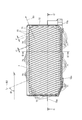
図10は、第2実施形態に係る排気パネル17の構成を示す正面図である。図11は、図10のE−E´断面図であり、図12は図10のF−F´断面図である。図13は、排気パネル17の背面図である。
<Second Embodiment>
FIG. 10 is a front view showing the configuration of the
第2実施形態では、プロジェクター100の筐体2に形成された排気口7aに、排気パネル7に代えて、排気パネル17を配置した例を示す。なお、第1実施形態と同一部分には、同一の符号を付して説明を省略する。
排気パネル17は、排気パネル7(図1)と同様に、筐体2の内部から排気口7aを通じて排気される排気を、排気方向B1方向に導く。
In the second embodiment, an example in which the
Similar to the exhaust panel 7 (FIG. 1), the
排気パネル17(規制部、開口用パネル)は、図10に示すように、略矩形に形成された枠172と、中空体171(規制体)とを備える。枠172の側端部には、取付部179a、179bがそれぞれ突出する。排気パネル17を排気口7a(図1)に取り付けた状態で、取付部179a、179bは、ねじ(図示略)等により右側面2Cに固定される。
As shown in FIG. 10, the exhaust panel 17 (regulatory portion, opening panel) includes a
中空体171は、断面6角形の空洞が互い違いに配列された、いわゆるハニカム構造を有する。中空体171に形成される各々の空洞は、排気パネル17において、筐体2の内側を向く面と外側を向く面とに連通する筒状である。この各々の空洞が、中空体171の内部において、筐体2の内側と外側とを結ぶ流路173を形成する。中空体171において、流路173を形成する壁を、特に壁部174とする。
The
図11に示すように、壁部174は、枠172の外側に沿う面172bに垂直な仮想基準線Iに対し、角θ4の傾きを有する。仮想基準線Iは、枠172の側部における内側の面172aと平行である。このため、プロジェクター100が第1設置状態(図1)で設置された場合、中空体171の流路173は、筐体2に対してスクリーンSC側を向く。
As shown in FIG. 11, the
また、壁部174は、図12に示すように、仮想面SP´に対して角θ5の傾きを有する。別の表現では、面172aの長辺に対して、角θ6の傾きで傾く。このため、プロジェクター100の第1設置状態では、流路173が、筐体2に対して上方へ向けられる。このため、排気方向B1が上向きとなる。角θ6は、鋭角であり、例えば、72°とすることができる。この流路173の傾きにより、画像光を下向きに投射する第1設置状態で流路173が上向きに向けられ、筐体2の内部から排気される空気を投射画像Pの画像光に重ならない方向に導くことができる。
Further, as shown in FIG. 12, the
この状態で、ユーザーが、仮想線SS(図1)より後方から筐体2を見る場合、排気パネル17をスクリーンSCの手前下側から見上げる格好になる。流路173が形成された中空体171は、壁部174が角θ4、θ5の傾きを有するので、ユーザーの視線を、中空体171により遮ることができる。さらに、中空体171は、不透明または遮光性を有する構成としてもよい。この場合、プロジェクター100の外から排気パネル17へ向けられた視線から、筐体2の内部を隠すことができる。
In this state, when the user looks at the
このように、中空体171の壁部174が筐体2に対し3次元的に傾けられるため、排気が投射画像Pの表示品位に影響しないという効果と、筐体2の内部をユーザーの視線から遮る効果とを得ることができる。
In this way, since the
また、排気パネル17は、例えば金型を用いた射出成形により、枠172と壁部174とを一体として製造でき、少ない部品点数で実現できる。中空体171がハニカム構造であることにより、金型に樹脂が流れ込みやすいという効果があり、壁部174の厚みを一定にすることが容易になる。
Further, the
中空体171がハニカム構造であることから、枠172及び中空体171を薄くしても、排気パネル17の強度が不足するのを抑制できる。具体的には、図12に符号t4で示す枠172の厚みを薄くすることができる。例えば、厚みt4を4mm以下とすることができる。流路173はハニカム構造の空洞であるため、筐体2の外側における流路173の開口面積が流路173の奥行(中空体171の厚み)に対して小さい。このため、枠172の厚みt4が薄くても、筐体2の外側から排気パネル17を通じて筐体2の内部を見た場合の視認性は低い。
Since the
また、壁部174の厚みt5(図12)を薄くすると、壁部174の面積に対する流路173の開口面積が大きくなる。つまり、筐体2の外側における排気パネル17の開口率が大きくなるので、排気パネル17を通じて排気される排気量を増やすことができる。厚みt5は、例えば、1mm以下とすることができる。この場合、筐体2の外側で開口する流路173の開口の大きさを、断面6角形を構成する一辺と対辺との幅wで表せば、幅wは、例えば、3.75mm以上とすることができる。
Further, when the thickness t5 (FIG. 12) of the
また、中空体171の一部の流路173に、図12に示すように、筐体2の内側を閉塞する閉塞部175が形成される。閉塞部175は、中空体171において、筐体2の外側に相当する面では開口し、筐体2の内側に相当する面では閉塞される。
Further, as shown in FIG. 12, a closing
閉塞部175は、排気パネル17を離型する場合に、イジェクトピンが押し当てられる箇所として使用できる。このように閉塞部175を使用することにより、金型を用いた製造方法により排気パネル17を製造する場合に離型が容易になる。また、閉塞部175は筐体2の内側に相当する面に形成されるため、閉塞部175が排気パネル17の外観に与える影響は小さい。
The closing
閉塞部175は、図13に示すように、中空体171の面内において一定の間隔で形成されるので、排気を妨げない効果がある。例えば、20か所の流路173のうち1か所の流路173に閉塞部175を形成することができる。閉塞部175に対応する空洞が一定の間隔で形成されることで、金型を用いる製造方法により排気パネル17を製造する場合に、金型に空洞を設けることができ、この空洞を、樹脂を注入するゲートとして使用できる。
As shown in FIG. 13, the closing
このように、第2実施形態の排気パネル17は、筒状の流路173が複数配列された中空体である中空体171を有する。この排気パネル17をプロジェクター100に設けることで、筐体2の内部から排気される空気を所望の方向に導く構成を、少ない部品点数で容易に実現できるという効果が得られる。
As described above, the
中空体171は排気口7aを覆うように配設され、各々の流路173が中空体171において、筐体2の外側と内側とに開口し、中空体171において、筐体2の内側における流路173の開口率が外側における流路173の開口率より低い。
このように、排気パネル17の金型には、閉塞部175に対応する空洞が一定の間隔で形成されるため、空洞をゲートとして使用することができる。これにより、金型に樹脂を充填させることが容易になる。
The
As described above, since the cavities corresponding to the closing
また、中空体171は、筐体2の外側において開口し、内側において閉塞された閉塞部175を有する。このように、閉塞部175は、排気パネル17を離型する場合に、イジェクトピンを押し当てられる箇所として使用される。これにより、排気パネル17の離型が容易になる。
Further, the
また、中空体171は、断面6角形の流路173が複数配列されたハニカム構造を有する。このように、中空体171がハニカム構造であることにより、排気パネル17の金型に形成されたハニカム構造に樹脂が流れ込みやすくなるため、流路173を形成する中空体171の厚みを一定に成型することが容易になる。
Further, the
<第3実施形態>
図14は、第3実施形態に係る排気パネル27の構成を示す断面図である。なお、第2実施形態と同一部分には、同一の符号を付して説明を省略する。
排気パネル27は、中空体171において、図14に示すように、筐体2の内側にテーパーが形成された閉塞部180を複数備えたものである。この構成では、排気パネル27を通じて筐体2の内部から外へ排気される空気が、閉塞部180のテーパーに沿って、流路173に抜けやすくなる。このため、排気パネル17に比べ、排気効率をより一層高める効果が期待できる。
<Third Embodiment>
FIG. 14 is a cross-sectional view showing the configuration of the
As shown in FIG. 14, the
なお、上述した各実施形態は、あくまでも本発明の一態様を示すものであり、本発明の範囲内で任意に変形及び応用が可能である。
例えば、上記各実施形態で説明したプロジェクター100は、筐体2の右側面2Cに形成された排気口7aに排気パネル7を設け、左側面2Dに形成された吸気口6aに吸気パネル6を設ける構成として説明した。本発明はこれに限定されず、吸気口6a及び排気口7aの位置、形状、サイズは任意である。例えば、排気口7aをプロジェクター100と同様に設けた構成において、吸気口6aに相当する開口を、天面2Aまたは底面2Bに設けてもよいし、背面2Eに設けてもよく、外気を給気する吸気口はスリット形状であってもよい。また、この吸気口にフィルター(図示略)を設けてもよい。また、排気口7a及び排気パネル7の位置は右側面2Cに限定されず、例えば、排気口7aを左側面2D側に設けてもよい。この場合、吸気口6aを右側面2Cに設ける構成とすることも可能である。また、吸気口6aのみを右側面2C又は左側面2Dに設け、排気口7aについては、天面2A、底面2B又は背面2Eに設けた構成にしてもよい。
It should be noted that each of the above-described embodiments shows only one aspect of the present invention, and can be arbitrarily modified and applied within the scope of the present invention.
For example, in the
また、上記実施形態では、水平方向Hにおいて略中央に位置する投射口8から、投射口8から背面2E側に向けて画像光を投射するプロジェクター100を例に挙げて説明したが、本発明はこれに限定されない。プロジェクター100は、例えば、筐体2の背面2Eまたは背面2Eとは反対側の端部に投射口8が設けられた構成としてもよい。このような構成であっても、第1及び第2設置状態で設置することが可能であり、本発明を適用できる。
Further, in the above embodiment, the
なお、プロジェクター100が短焦点型ではなく、プロジェクター100からスクリーンSCまでの距離が比較的長い場合には、プロジェクター100とスクリーンSCとの間にユーザーが位置することが想定され、この位置のユーザーからは吸気パネル6や排気パネル7を通して筐体2の内部が比較的見えやすくなってしまう。しかしながら、ユーザーは、主に前方のスクリーンSCを見るため、プロジェクター100の前方(スクリーンSC側)にいるユーザーにとって、後方にあるプロジェクターが視界に入る機会は少なく、その影響は小さい。本実施形態のプロジェクター100は、スクリーンSCとプロジェクター100の双方が同時に視界に入るユーザー、すなわちプロジェクター100の後方に位置しているユーザーから見て筐体2の内部が見えにくくなっているため有益である。
If the
また、第1及び第2設置状態において、プロジェクター100の仮想水平面SPは、天井面S1、床面S2及びその他の水平面と完全に平行な面である必要はない。実施形態で説明したその他の水平、垂直、平行の各表現も、完全な水平、垂直、平行に制限することを意図していない。
Further, in the first and second installation states, the virtual horizontal plane SP of the
また、プロジェクター100が備える投射部10の構成、筐体2の形状やサイズ等の細部構成についても任意に変更可能であり、各実施形態で具体例として挙げた数値はあくまで一例である。各図に示した排気パネル7、17、27におけるフィン71の数、流路73、173の数等は任意に変更可能であり、プロジェクター100のサイズ等に対応して適宜に決定すればよい。また、角θ1、θ2、θ3、θ4、θ5、θ6の大きさも任意に調整可能である。
Further, the configuration of the
さらに、吸気パネル6及び排気パネル7、17、27の製造方法は、金型を用いる射出成形等の方法に限定されず、例えば、フィン71と枠72とを個別に製造して接合する方法や、削り出し、3Dプリンターによる成型など、種々の方法を用いることができる。また、吸気パネル6及び排気パネル7、17、27の材料も任意であり、その他の細部構成についても任意に変更可能である。
Further, the manufacturing method of the
2…筐体、2A…天面、2B…底面、2C…右側面、2D…右側面、2D…左側面、2E…背面、6…吸気パネル、6a…吸気口、7…排気パネル(規制部、開口用パネル)、7a…排気口、8…投射口(投射部)、9…排気装置、10…投射部、17…排気パネル(規制部、開口用パネル)、21…設置部、27…排気パネル(規制部、開口用パネル)、71…フィン(規制体)、72…枠、72a…下面、72b…面、73…流路、74…リブ、100…プロジェクター、171…中空体(規制体)、172…枠、172a…面、172b…面、173…流路、174…壁部、175…閉塞部、179a…取付部、179b…取付部、180…閉塞部、200…取付アーム、210…設置台、A…投射方向、B1…排気方向、B2…吸気方向、H…水平方向、P…投射画像、S1…天井面、S2…床面、S3…壁面、SC…スクリーン、SS…仮想線、V…上下方向。 2 ... Housing, 2A ... Top surface, 2B ... Bottom surface, 2C ... Right side surface, 2D ... Right side surface, 2D ... Left side surface, 2E ... Back surface, 6 ... Intake panel, 6a ... Intake port, 7 ... Exhaust panel (Regulatory part) , Opening panel), 7a ... Exhaust port, 8 ... Projection port (projection unit), 9 ... Exhaust device, 10 ... Projection unit, 17 ... Exhaust panel (regulatory unit, opening panel), 21 ... Installation unit, 27 ... Exhaust panel (regulator, opening panel), 71 ... fin (regulator), 72 ... frame, 72a ... bottom surface, 72b ... surface, 73 ... flow path, 74 ... rib, 100 ... projector, 171 ... hollow body (regulation) Body), 172 ... frame, 172a ... surface, 172b ... surface, 173 ... flow path, 174 ... wall part, 175 ... closed part, 179a ... mounting part, 179b ... mounting part, 180 ... closed part, 200 ... mounting arm, 210 ... Installation stand, A ... Projection direction, B1 ... Exhaust direction, B2 ... Intake direction, H ... Horizontal direction, P ... Projection image, S1 ... Ceiling surface, S2 ... Floor surface, S3 ... Wall surface, SC ... Screen, SS ... Virtual line, V ... Vertical direction.
Claims (9)
天面及び底面を有する筐体と、
前記天面または前記底面に平行であって前記プロジェクターの設置状態で水平となる仮想面に対して上側または下側に傾いた投射方向に画像を投射する投射部と、
前記筐体に形成された開口に設けられ、前記開口を通して排出または吸入される空気の進行方向を規制する規制部と、を備え、
前記開口は、前記筐体において、前記画像の投射方向に向かって左側および右側の少なくとも一方の側面に形成され、
前記規制部は、前記筐体の内側と外側とを結ぶ流路を形成する複数の板状の規制体を有し、
前記規制体は、不透明または遮光性を有する面を有し、
前記規制体は、前記筐体の前記内側から前記外側に向かうにつれて、前記側面を正面視した場合に前記仮想面に対して前記投射方向側に傾き、前記仮想面と平行な断面において前記側面に対して前記投射方向側に傾き、前記仮想面に垂直な断面において前記仮想面に対して前記投射方向と上下方向に逆向きに傾き、前記画像の投射方向とは上下反対であって前記投射面に近づくような傾きを有する前記流路を形成すること、
を特徴とするプロジェクター。 A projector that projects an image onto a projection surface.
A housing with a top and bottom,
A projection unit that projects an image in a projection direction that is parallel to the top surface or the bottom surface and is inclined upward or downward with respect to a virtual surface that is horizontal in the installed state of the projector.
A regulating portion provided in the opening formed in the housing and regulating the traveling direction of air discharged or sucked through the opening is provided.
The openings are formed in the housing on at least one side surface on the left side and the right side in the projection direction of the image.
The restricting portion has a plurality of plate-shaped restricting bodies forming a flow path connecting the inside and the outside of the housing.
The regulator has an opaque or light-shielding surface and
The restricting body tilts toward the projection direction with respect to the virtual surface when the side surface is viewed from the front as it goes from the inside to the outside of the housing, and on the side surface in a cross section parallel to the virtual surface. On the other hand, it tilts toward the projection direction, tilts in the direction opposite to the projection direction with respect to the virtual surface in a cross section perpendicular to the virtual surface, and is vertically opposite to the projection direction of the image. To form the flow path having an inclination approaching
A projector featuring.
前記画像の投射方向は、前記天面または前記底面に平行であって前記プロジェクターの設置状態で水平となる仮想面に対して上側または下側に傾いた方向であって、
前記開口は、前記筐体において、前記画像の投射方向に向かって右側および左側の少なくとも一方の側面に形成され、
前記開口用パネルが前記開口に取り付けられた状態において、前記開口用パネルは、前記筐体の内側と外側とを結ぶ流路を形成する複数の板状の規制体を有し、
前記規制体は、不透明または遮光性を有する面を有し、
前記規制体は、前記筐体の前前記内側から外側に向かうにつれて、前記側面を正面視した場合に前記仮想面に対して前記投射方向側に傾き、前記仮想面と平行な断面において前記側面に対して前記投射方向側に傾き、前記仮想面に垂直な断面において前記仮想面に対して前記投射方向と上下方向に逆向きに傾き、前記画像の投射方向とは上下反対であって前記投射面に近づくような傾きを有する前記流路を形成すること、
を特徴とする開口用パネル。
In a projector that projects an image on a projection surface, it is an opening panel that is attached to an opening formed in the housing of the projector having a top surface and a bottom surface.
The projection direction of the image is a direction inclined upward or downward with respect to a virtual surface parallel to the top surface or the bottom surface and horizontal in the installed state of the projector.
The openings are formed in the housing on at least one side surface on the right side and the left side in the projection direction of the image.
In a state where the opening panel is attached to the opening, the opening panel has a plurality of plate-shaped regulators forming a flow path connecting the inside and the outside of the housing.
The regulator has an opaque or light-shielding surface and
The restrictor tilts toward the projection direction with respect to the virtual surface when the side surface is viewed from the front as the front side of the housing is directed from the inside to the outside, and the restrictor is inclined to the side surface in a cross section parallel to the virtual surface. On the other hand, it tilts toward the projection direction, tilts in the direction opposite to the projection direction with respect to the virtual surface in a cross section perpendicular to the virtual surface, and is vertically opposite to the projection direction of the image. To form the flow path having an inclination approaching
A panel for opening that features.
Priority Applications (3)
| Application Number | Priority Date | Filing Date | Title |
|---|---|---|---|
| JP2017063635A JP6950231B2 (en) | 2017-03-28 | 2017-03-28 | Projector and aperture panel |
| US15/919,495 US10288989B2 (en) | 2017-03-28 | 2018-03-13 | Projector and panel for opening |
| CN201810251787.7A CN108663873A (en) | 2017-03-28 | 2018-03-26 | Projecting apparatus and opening panel |
Applications Claiming Priority (1)
| Application Number | Priority Date | Filing Date | Title |
|---|---|---|---|
| JP2017063635A JP6950231B2 (en) | 2017-03-28 | 2017-03-28 | Projector and aperture panel |
Publications (3)
| Publication Number | Publication Date |
|---|---|
| JP2018165801A JP2018165801A (en) | 2018-10-25 |
| JP2018165801A5 JP2018165801A5 (en) | 2020-03-26 |
| JP6950231B2 true JP6950231B2 (en) | 2021-10-13 |
Family
ID=63672528
Family Applications (1)
| Application Number | Title | Priority Date | Filing Date |
|---|---|---|---|
| JP2017063635A Active JP6950231B2 (en) | 2017-03-28 | 2017-03-28 | Projector and aperture panel |
Country Status (3)
| Country | Link |
|---|---|
| US (1) | US10288989B2 (en) |
| JP (1) | JP6950231B2 (en) |
| CN (1) | CN108663873A (en) |
Families Citing this family (6)
| Publication number | Priority date | Publication date | Assignee | Title |
|---|---|---|---|---|
| US10836318B2 (en) * | 2017-10-16 | 2020-11-17 | SMR Patents S.à.r.l. | Logo lamp assembly and method of using same |
| CN111290200B (en) * | 2018-12-06 | 2021-12-07 | 中强光电股份有限公司 | Projection device |
| CN109618141A (en) * | 2018-12-24 | 2019-04-12 | 北京易创盈互联网科技有限公司 | A kind of ultrashort out-of-focus projection's method and device of passenger's new media |
| US11466812B1 (en) * | 2019-11-11 | 2022-10-11 | Michael Edward Kelley | Universally adjusting ultra short throw projector credenza |
| CN114114801A (en) * | 2020-08-27 | 2022-03-01 | 青岛海信激光显示股份有限公司 | Projection device |
| CN114114799A (en) * | 2020-08-27 | 2022-03-01 | 青岛海信激光显示股份有限公司 | Projection device |
Family Cites Families (24)
| Publication number | Priority date | Publication date | Assignee | Title |
|---|---|---|---|---|
| US6109767A (en) | 1996-03-29 | 2000-08-29 | Minnesota Mining And Manufacturing Company | Honeycomb light and heat trap for projector |
| US6568814B2 (en) * | 1999-03-03 | 2003-05-27 | 3M Innovative Properties Company | Integrated front projection system with shaped imager and associated method |
| JP2001350199A (en) | 2000-06-05 | 2001-12-21 | Matsushita Electric Ind Co Ltd | Projection type display device |
| JP4265289B2 (en) * | 2003-06-05 | 2009-05-20 | 株式会社日立製作所 | Projection display |
| JP4265314B2 (en) * | 2003-07-04 | 2009-05-20 | セイコーエプソン株式会社 | Louvered duct and projector |
| JP2005234424A (en) * | 2004-02-23 | 2005-09-02 | Casio Comput Co Ltd | Projector |
| JP2005275200A (en) * | 2004-03-26 | 2005-10-06 | Sanyo Electric Co Ltd | Projection type image display device |
| JP2006337897A (en) * | 2005-06-06 | 2006-12-14 | Mitsubishi Electric Corp | Projector apparatus and exhaust control system |
| JP2008203450A (en) * | 2007-02-19 | 2008-09-04 | Seiko Epson Corp | Electronic equipment |
| JP4901595B2 (en) * | 2007-03-06 | 2012-03-21 | 三洋電機株式会社 | Projection display |
| JP4967773B2 (en) * | 2007-04-12 | 2012-07-04 | ソニー株式会社 | Projection display |
| JP2008262062A (en) * | 2007-04-12 | 2008-10-30 | Sony Corp | Projection display device |
| JP5197117B2 (en) * | 2008-04-10 | 2013-05-15 | キヤノン株式会社 | Image projection apparatus and image display system |
| JP5380207B2 (en) * | 2009-08-27 | 2014-01-08 | 日立コンシューマエレクトロニクス株式会社 | Projection display |
| JPWO2011039834A1 (en) * | 2009-09-29 | 2013-02-21 | Necディスプレイソリューションズ株式会社 | Projector device |
| JP2011118152A (en) * | 2009-12-03 | 2011-06-16 | Nippon Avionics Co Ltd | Projection type display apparatus |
| JP5450247B2 (en) * | 2010-05-17 | 2014-03-26 | 三洋電機株式会社 | Projection display |
| JP2013041135A (en) * | 2011-08-17 | 2013-02-28 | Seiko Epson Corp | Projector |
| JP6127533B2 (en) * | 2013-01-22 | 2017-05-17 | セイコーエプソン株式会社 | projector |
| CN203375576U (en) * | 2013-06-03 | 2014-01-01 | 美的集团股份有限公司 | Air outlet mesh enclosure and air conditioner |
| JP6205864B2 (en) * | 2013-06-04 | 2017-10-04 | セイコーエプソン株式会社 | projector |
| JP2015108779A (en) * | 2013-12-05 | 2015-06-11 | セイコーエプソン株式会社 | Light source device and projector |
| JP6238059B2 (en) * | 2013-12-18 | 2017-11-29 | カシオ計算機株式会社 | Projection apparatus and projection method |
| JP6547298B2 (en) * | 2015-01-06 | 2019-07-24 | セイコーエプソン株式会社 | projector |
-
2017
- 2017-03-28 JP JP2017063635A patent/JP6950231B2/en active Active
-
2018
- 2018-03-13 US US15/919,495 patent/US10288989B2/en active Active
- 2018-03-26 CN CN201810251787.7A patent/CN108663873A/en active Pending
Also Published As
| Publication number | Publication date |
|---|---|
| CN108663873A (en) | 2018-10-16 |
| JP2018165801A (en) | 2018-10-25 |
| US20180284581A1 (en) | 2018-10-04 |
| US10288989B2 (en) | 2019-05-14 |
Similar Documents
| Publication | Publication Date | Title |
|---|---|---|
| JP6950231B2 (en) | Projector and aperture panel | |
| US7950811B2 (en) | Projection display device | |
| JP5378112B2 (en) | Projection-type image display device | |
| EP2192342B1 (en) | Light source cooling device and projection display device with the same | |
| US20090051829A1 (en) | Projection display device | |
| JP6590249B2 (en) | Image projection device | |
| JP5263993B2 (en) | Light source cooling device, projection display device, and light source cooling method | |
| JP2017054013A (en) | Image projection device | |
| JP5232132B2 (en) | Lamp unit and projector | |
| JP2015162391A (en) | Housing for light source, light source device and image projection device | |
| JP5879814B2 (en) | projector | |
| JP2017054012A (en) | Image projection device | |
| WO2011039834A1 (en) | Projector device | |
| JP4877822B2 (en) | Projection display device | |
| EP1840642B1 (en) | Projector | |
| JP6301423B1 (en) | Lighting device | |
| JP6590248B2 (en) | Image projection device | |
| JP4053016B2 (en) | Lamp unit | |
| JP6308577B2 (en) | LIGHT SOURCE DEVICE, PROJECTION DISPLAY DEVICE HAVING THE SAME, AND COOLING METHOD FOR LIGHT SOURCE DEVICE | |
| JP2012113073A (en) | Light source unit and projection type display device including the same | |
| JP7373741B2 (en) | projector | |
| JP5366228B2 (en) | Light source cooling device, projection display device, and light source cooling method | |
| JP6598059B2 (en) | Image projection device | |
| JP6341534B2 (en) | Light source device and projection display device | |
| JP6206584B2 (en) | Projector device |
Legal Events
| Date | Code | Title | Description |
|---|---|---|---|
| A521 | Written amendment |
Free format text: JAPANESE INTERMEDIATE CODE: A523 Effective date: 20200210 |
|
| A621 | Written request for application examination |
Free format text: JAPANESE INTERMEDIATE CODE: A621 Effective date: 20200210 |
|
| A977 | Report on retrieval |
Free format text: JAPANESE INTERMEDIATE CODE: A971007 Effective date: 20210205 |
|
| A131 | Notification of reasons for refusal |
Free format text: JAPANESE INTERMEDIATE CODE: A131 Effective date: 20210216 |
|
| A521 | Written amendment |
Free format text: JAPANESE INTERMEDIATE CODE: A523 Effective date: 20210407 |
|
| A131 | Notification of reasons for refusal |
Free format text: JAPANESE INTERMEDIATE CODE: A131 Effective date: 20210518 |
|
| A521 | Written amendment |
Free format text: JAPANESE INTERMEDIATE CODE: A523 Effective date: 20210708 |
|
| TRDD | Decision of grant or rejection written | ||
| A01 | Written decision to grant a patent or to grant a registration (utility model) |
Free format text: JAPANESE INTERMEDIATE CODE: A01 Effective date: 20210824 |
|
| A61 | First payment of annual fees (during grant procedure) |
Free format text: JAPANESE INTERMEDIATE CODE: A61 Effective date: 20210906 |
|
| R150 | Certificate of patent or registration of utility model |
Ref document number: 6950231 Country of ref document: JP Free format text: JAPANESE INTERMEDIATE CODE: R150 |