JP6946261B2 - Implantable nerve stimulators and methods with internal electronics without ASICs - Google Patents
Implantable nerve stimulators and methods with internal electronics without ASICs Download PDFInfo
- Publication number
- JP6946261B2 JP6946261B2 JP2018500525A JP2018500525A JP6946261B2 JP 6946261 B2 JP6946261 B2 JP 6946261B2 JP 2018500525 A JP2018500525 A JP 2018500525A JP 2018500525 A JP2018500525 A JP 2018500525A JP 6946261 B2 JP6946261 B2 JP 6946261B2
- Authority
- JP
- Japan
- Prior art keywords
- current
- differential amplifier
- conductor
- source
- voltage
- Prior art date
- Legal status (The legal status is an assumption and is not a legal conclusion. Google has not performed a legal analysis and makes no representation as to the accuracy of the status listed.)
- Active
Links
Images


Classifications
-
- A—HUMAN NECESSITIES
- A61—MEDICAL OR VETERINARY SCIENCE; HYGIENE
- A61N—ELECTROTHERAPY; MAGNETOTHERAPY; RADIATION THERAPY; ULTRASOUND THERAPY
- A61N1/00—Electrotherapy; Circuits therefor
- A61N1/02—Details
- A61N1/04—Electrodes
- A61N1/05—Electrodes for implantation or insertion into the body, e.g. heart electrode
-
- A—HUMAN NECESSITIES
- A61—MEDICAL OR VETERINARY SCIENCE; HYGIENE
- A61N—ELECTROTHERAPY; MAGNETOTHERAPY; RADIATION THERAPY; ULTRASOUND THERAPY
- A61N1/00—Electrotherapy; Circuits therefor
- A61N1/18—Applying electric currents by contact electrodes
- A61N1/32—Applying electric currents by contact electrodes alternating or intermittent currents
- A61N1/36—Applying electric currents by contact electrodes alternating or intermittent currents for stimulation
- A61N1/3605—Implantable neurostimulators for stimulating central or peripheral nerve system
- A61N1/36125—Details of circuitry or electric components
-
- A—HUMAN NECESSITIES
- A61—MEDICAL OR VETERINARY SCIENCE; HYGIENE
- A61N—ELECTROTHERAPY; MAGNETOTHERAPY; RADIATION THERAPY; ULTRASOUND THERAPY
- A61N1/00—Electrotherapy; Circuits therefor
- A61N1/02—Details
- A61N1/04—Electrodes
- A61N1/05—Electrodes for implantation or insertion into the body, e.g. heart electrode
- A61N1/0551—Spinal or peripheral nerve electrodes
-
- A—HUMAN NECESSITIES
- A61—MEDICAL OR VETERINARY SCIENCE; HYGIENE
- A61N—ELECTROTHERAPY; MAGNETOTHERAPY; RADIATION THERAPY; ULTRASOUND THERAPY
- A61N1/00—Electrotherapy; Circuits therefor
- A61N1/18—Applying electric currents by contact electrodes
- A61N1/32—Applying electric currents by contact electrodes alternating or intermittent currents
- A61N1/36—Applying electric currents by contact electrodes alternating or intermittent currents for stimulation
- A61N1/36007—Applying electric currents by contact electrodes alternating or intermittent currents for stimulation of urogenital or gastrointestinal organs, e.g. for incontinence control
-
- A—HUMAN NECESSITIES
- A61—MEDICAL OR VETERINARY SCIENCE; HYGIENE
- A61N—ELECTROTHERAPY; MAGNETOTHERAPY; RADIATION THERAPY; ULTRASOUND THERAPY
- A61N1/00—Electrotherapy; Circuits therefor
- A61N1/18—Applying electric currents by contact electrodes
- A61N1/32—Applying electric currents by contact electrodes alternating or intermittent currents
- A61N1/36—Applying electric currents by contact electrodes alternating or intermittent currents for stimulation
- A61N1/3605—Implantable neurostimulators for stimulating central or peripheral nerve system
- A61N1/36128—Control systems
- A61N1/36135—Control systems using physiological parameters
-
- A—HUMAN NECESSITIES
- A61—MEDICAL OR VETERINARY SCIENCE; HYGIENE
- A61N—ELECTROTHERAPY; MAGNETOTHERAPY; RADIATION THERAPY; ULTRASOUND THERAPY
- A61N1/00—Electrotherapy; Circuits therefor
- A61N1/18—Applying electric currents by contact electrodes
- A61N1/32—Applying electric currents by contact electrodes alternating or intermittent currents
- A61N1/36—Applying electric currents by contact electrodes alternating or intermittent currents for stimulation
- A61N1/372—Arrangements in connection with the implantation of stimulators
- A61N1/375—Constructional arrangements, e.g. casings
- A61N1/3752—Details of casing-lead connections
- A61N1/3754—Feedthroughs
-
- A—HUMAN NECESSITIES
- A61—MEDICAL OR VETERINARY SCIENCE; HYGIENE
- A61N—ELECTROTHERAPY; MAGNETOTHERAPY; RADIATION THERAPY; ULTRASOUND THERAPY
- A61N1/00—Electrotherapy; Circuits therefor
- A61N1/18—Applying electric currents by contact electrodes
- A61N1/32—Applying electric currents by contact electrodes alternating or intermittent currents
- A61N1/36—Applying electric currents by contact electrodes alternating or intermittent currents for stimulation
- A61N1/372—Arrangements in connection with the implantation of stimulators
- A61N1/378—Electrical supply
- A61N1/3787—Electrical supply from an external energy source
Description
(関連出願の引用)
本願は、米国仮出願第62/191,134号(2015年7月10日出願、名称「IMPLANTABLE NERVE STIMULATOR HAVING INTERNAL ELECTRONICS WITHOUT ASIC AND METHODS OF USE」)の利益を主張し、上記出願の全体は、参照により本明細書に引用される。本願は、以下の出願に関連する:米国仮出願第62/038,122号(2014年8月15日出願、名称「Devices and Methods for Anchoring of Neurostimulation Leads」)、米国仮出願第62/038,131号(2014年8月15日出願、名称「External Pulse Generator Device and Associated Methods for Trial Nerve Stimulation」、代理人事件番号97672−001100US)、米国仮出願第62/041,611号(2014年8月25日出願、名称「Electromyographic Lead Positioning and Stimulation Titration in a Nerve Stimulation System for Treatment of Overactive Bladder,Pain and Other Indicators」、代理人事件番号97672−001200US)、米国仮出願第62/110,274号(2015年1月30日出願、名称「Implantable Lead Affixation Structure for Nerve Stimulation to Alleviate Bladder Dysfunction and Other Indications」、代理人事件番号97672−001010US)、および、米国仮出願第62/101,888号(名称「Electromyographic Lead Positioning and Stimulation Titration in a Nerve Stimulation System for Treatment of Overactive Bladder」、代理人事件番号97672−001210US)、米国仮出願第62,101,899号(名称「Integrated Electromyographic Clinician Programmer For Use With an Implantable Neurostimulator」、代理人事件番号97672−001220US)、米国仮出願第62/101,897号(名称「Systems and Methods for Neurostimulation Electrode Configurations Based on Neural Localization」、代理人事件番号97672−001230US)、米国仮出願第62/101,666号(名称「Patient Remote and Associated Methods of Use With aNerve Stimulation System」、代理人事件番号97672−001400US)、米国仮出願第62/101,884号(名称「Attachment Devices and Associated Methods of Use With aNerve Stimulation Charging Device」、代理人事件番号97672−001500US)、米国仮出願第62/101,782号(名称「Improved Antenna and Methods of Use For an Implantable Nerve Stimulator」、代理人事件番号97672− 001600US)(以上の全ては2015年1月9日出願)。
上記出願の各々は、出願人に譲渡され、あらゆる目的のためにその全体が参照により本明細書に引用される。
(Citation of related application)
The present application claims the interests of US Provisional Application No. 62 / 191,134 (filed July 10, 2015, named "IMPLANTABLE NERVE STIMULATOR HAVING INTERNAL ELECTRONICS WITHOUT ASIC AND METHODS OF USE"). Reference is made herein. This application relates to the following applications: US Provisional Application No. 62 / 038,122 (filed August 15, 2014, named "Devices and Methods for Anchoring of Neurostimulation Leads"), US Provisional Application No. 62/038, No. 131 (filed on August 15, 2014, name "External Pulse Generator Device and Assisted Methods for Trial Nerve Stimulation", Agent Case No. 97672-001100US), US Provisional Application No. 62/041,11 Application on the 25th, named "Electromyogratic Lead Positioning and Stimulation Transition in a Nerve Stimulation System for Treatment System for Treatment for Treatment of Overactive Bladder, Case No. 17 Filed January 30, 2014, Named "Implantable Lead Affiliation Stimulation for Nerve Stimulation to Alleviate Bladder Dysfunction and Other Indications", Agent Case No. 97672-0010 US Lead Positioning and Stimulation Titration in a Nerve Stimulation System for Treatment of Overactive Bladder ", attorney docket number 97672-001210US), US provisional application No. 62,101,899 (entitled" Integrated Electromyographic Clinician Programmer For Use With an Implantable Neurostimulator " , Agent Case No. 97672-001220US), US Provisional Application No. 62 / 101,897 (named "Systems and Methods for Nerve") Ostimulation Electrode Configurations Based on Natural Localization ”, Agent Case No. 97672-001230US), US Provisional Application No. 62 / 101,666 (named“ Patient Remote and Assisted System Case ” 001400US), U.S. Provisional Application No. 62 / 101,884 (name "Attachment Devices and Assisted Methods of Use With aNerve Simulation Device", Agent Case No. 97672-0015000, U.S.A. Name "Improved Antonio and Patients of Use For an Patient Nerve Systemor", Agent Case No. 97672-001600US (all of the above filed on January 9, 2015).
Each of the above applications is assigned to the applicant and is incorporated herein by reference in its entirety for all purposes.
本開示は、神経刺激治療システムおよび関連デバイス、ならびにそのような治療システムの治療、埋め込み、および構成の方法に関する。 The present disclosure relates to neurostimulation treatment systems and related devices, as well as methods of treatment, implantation, and construction of such treatment systems.
埋め込み可能神経刺激システムを用いた治療は、近年、ますます一般的になっている。そのようなシステムは、いくつかの状態を治療することにおいて有望性を示しているが、治療の有効性は、患者間で著しく変動し得る。いくつかの要因は、患者が経験する非常に異なる転帰につながり得、治療の実行可能性は、埋め込みの前に決定することが困難であり得る。例えば、刺激システムは、多くの場合、1つ以上の標的神経構造を治療するために、電極のアレイを利用する。電極は、多くの場合、多電極導線上に一緒に搭載され、導線は、標的神経構造への電極の電気結合をもたらすことを意図している位置において患者の組織に埋め込まれ、典型的には、結合の少なくとも一部は、中間組織を介して提供される。他のアプローチも、1つ以上の電極とともに採用され得、1つ以上の電極は、例えば、標的神経構造を覆う皮膚に取り付けられるか、標的神経の周囲でカフに埋め込まれる。それにもかかわらず、医師は、典型的には、電極に印加される電気刺激を変動させることによって、適切な治療プロトコルの確立を模索するであろう。 Treatment with implantable nerve stimulation systems has become more and more common in recent years. Although such systems show promise in treating some conditions, the effectiveness of treatment can vary significantly between patients. Several factors can lead to very different outcomes that patients experience, and the feasibility of treatment can be difficult to determine prior to implantation. For example, stimulation systems often utilize an array of electrodes to treat one or more target neural structures. The electrodes are often mounted together on a multi-electrode lead, which is implanted in the patient's tissue at a location intended to provide electrical coupling of the electrode to the target neural structure, typically. , At least part of the bond is provided via the intermediate tissue. Other approaches can also be employed with one or more electrodes, which are attached, for example, to the skin covering the target nerve structure or implanted in the cuff around the target nerve. Nevertheless, physicians will typically seek to establish appropriate treatment protocols by varying the electrical stimulation applied to the electrodes.
現在の刺激電極設置/埋め込み技法および公知の治療設定技法は、有意な不利点に悩まされている。異なる患者の神経組織構造は、非常に異なり得、特定の機能を果たし、および/または特定の器官を衰弱させている神経の場所ならびに分岐は、正確に予測もしくは識別することが困難である。標的神経構造を包囲する組織構造の電気特性も、異なる患者間で非常に異なり得、刺激に対する神経反応は、著しく異なり得、ある患者の身体機能に影響を及ぼすために効果的である電気刺激パルスパターン、周波数、および/または電圧が、別の患者に有意な疼痛を与え得るか、もしくは限定された影響を及ぼし得る。神経刺激システムの埋め込みが効果的治療を提供する患者でさえも、刺激プロトコルに対する頻繁な調節および変更が、多くの場合、好適な治療プログラムが決定され得る前に要求され、多くの場合、有効性が達成される前に、反復通院および患者にとって有意な不快感を伴う。いくつかの複雑かつ高度な導線構造および刺激設定プロトコルが、これらの課題の克服を模索するために実装されているが、導線設置結果における変動性、好適な刺激信号を確立するための臨床医の時間、および患者に与えられる不快感(場合によっては、有意な疼痛)は、理想的とは言えないままである。加えて、そのようなデバイスの寿命およびバッテリ寿命は、埋め込み式システムが数年毎に定期的に交換されるように比較的に短く、それは、追加の外科手術、患者不快感、および有意な費用を医療システムに要求する。 Current stimulation electrode placement / implantation techniques and known treatment setting techniques suffer from significant disadvantages. Nervous tissue structures in different patients can be very different, and the location and branching of nerves that perform a particular function and / or debilitate a particular organ is difficult to accurately predict or identify. The electrical properties of the tissue structure surrounding the target neural structure can also be very different between different patients, and the neural response to the stimulus can be significantly different, an electrical stimulation pulse that is effective in affecting the physical function of one patient. Patterns, frequencies, and / or voltages can cause significant pain or have a limited effect on another patient. Frequent adjustments and changes to the stimulation protocol are often required before a suitable treatment program can be determined, and are often effective, even in patients whose implantation of the neural stimulation system provides effective treatment. With repeated visits and significant discomfort for the patient before is achieved. Several complex and advanced conductor structures and stimulus configuration protocols have been implemented to seek to overcome these challenges, but the variability in conductor installation results, the clinician's ability to establish suitable stimulus signals. The time and discomfort (in some cases, significant pain) given to the patient remains less than ideal. In addition, the life and battery life of such devices is relatively short, as the implantable system is replaced regularly every few years, which is an additional surgical procedure, patient discomfort, and significant cost. To the medical system.
さらに、現在の刺激システムは、電極の電流のソースおよびシンクを管理するために、精巧な回路設計に依拠する。多くの事例では、これらの回路の複雑性は、特定用途向け集積回路(ASIC)内に設置されるようなものである。そのようなASICは、ASICが回路のコンパクトなパッケージングを可能にし、コンパクトなパッケージングが埋め込み可能デバイスの分野において有益であるという点において利点を提供する。しかしながら、ASICは、設計および製造が高価であり、新しいASIC設計が所望されるとき、長期ターンアラウンドタイムを有する。 In addition, current stimulation systems rely on elaborate circuit design to control the source and sink of electrode current. In many cases, the complexity of these circuits is such that they are installed within an application specific integrated circuit (ASIC). Such ASICs provide an advantage in that ASICs allow for compact packaging of circuits, which is beneficial in the field of implantable devices. However, ASICs are expensive to design and manufacture and have long turnaround times when new ASIC designs are desired.
これらの神経刺激療法の多くの利点は、完全には実現されていない。したがって、改良型神経刺激方法、システム、およびデバイス、ならびに治療されている特定の患者または状態のために、そのような神経刺激システムを埋め込み、構成するための方法を提供することが望ましい。システムを埋め込み、構成することにおける医師による使用の容易性を向上させるように、ならびに患者快適性および患者の症状の緩和を向上させるように、および/または電流ソースならびにシンクのための再設計された回路を提供して、埋め込み可能デバイスの製造能力および制御能力を改良するように、そのようなシステムおよび方法を提供することが、特に有用であろう。 Many of the benefits of these neurostimulation therapies have not been fully realized. Therefore, it is desirable to provide improved neural stimulation methods, systems, and devices, as well as methods for implanting and configuring such neural stimulation systems for the particular patient or condition being treated. Redesigned to improve ease of use by physicians in implanting and configuring the system, and to improve patient comfort and alleviation of patient symptoms, and / or for current sources and sinks. It would be particularly useful to provide such systems and methods to provide circuits to improve the manufacturing and control capabilities of implantable devices.
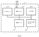
本開示は、埋め込み可能神経刺激装置に関し、より具体的には、埋め込み可能パルス発生器(IPG)に関する。IPGは、選択可能に、電流を標的組織にソースし、電流をそこからシンクするように構成されている電流ソース/シンクを含むことができる。選択可能に、電流を標的組織にソースし、電流をそこからシンクする電流ソース/シンクのこの能力は、IPG内の構成要素の数を減少させ、したがって、より小さく、かつよりコンパクトなIPGを可能にする。加えて、そのような選択可能電流ソース/シンクは、依然として小サイズを維持しながら、既製の構成要素を用いて作製されることを可能にするという利点を提供する。故に、そのような電流ソース/シンクを伴うIPGは、電流ソース/シンクのために使用されていたASICを排除することができる。このASICの排除は、IPGの設計および製造コストを削減し、より迅速かつより容易な設計変更を可能にする。 The present disclosure relates to implantable nerve stimulators, and more specifically to implantable pulse generators (IPGs). The IPG can optionally include a current source / sink that is configured to source and sink current to the target tissue. This ability of the current source / sink to selectively source and sink current to the target tissue reduces the number of components within the IPG and thus allows for a smaller and more compact IPG. To. In addition, such selectable current sources / sinks offer the advantage of being able to be made using off-the-shelf components while still maintaining a small size. Therefore, an IPG with such a current source / sink can eliminate the ASIC used for the current source / sink. This elimination of ASICs reduces IPG design and manufacturing costs and allows for faster and easier design changes.
電流ソース/シンクは、電流駆動差動増幅器を介して、選択可能に、電流を標的組織にソースし、電流をそこからシンクするように構成されていることができる。電流駆動差動増幅器は、その反転および非反転入力に供給される電圧に基づいて、選択的に、電流をソースまたはシンクする。いくつかの実施形態では、電流駆動差動増幅器の反転入力は、電流駆動差動増幅器の非反転入力に供給可能な最大電圧と最小電圧との間の中間の電圧を供給されることができる。そのような実施形態では、電流駆動差動増幅器の非反転入力に提供される電圧は、電流駆動差動増幅器に、電流を標的組織にソースさせるか、または電流をそこからシンクさせるかのために選択されることができる。 The current source / sink can be optionally configured to source current to and sink current from the target tissue via a current driven differential amplifier. The current-driven differential amplifier selectively sources or sinks current based on the voltage supplied to its inverting and non-inverting inputs. In some embodiments, the inverting input of the current driven differential amplifier can be supplied with an intermediate voltage between the maximum and minimum voltages that can be supplied to the non-inverting input of the current driven differential amplifier. In such an embodiment, the voltage provided to the non-inverting input of the current-driven differential amplifier is for causing the current-driven differential amplifier to either source the current to the target tissue or sink the current from it. Can be selected.
本開示の一側面は、1つ以上の電気パルスを患者の体内の標的領域に送達するための埋め込み可能神経刺激装置システムに関する。埋め込み可能神経刺激装置システムは、導線の遠位端上に位置する複数の電極を有する、埋め込み可能導線であって、電極は、患者の体内の標的領域に近接して位置付け可能であり、電気刺激を標的領域に提供する、埋め込み可能導線と、導線の近位端に電気的に結合されている埋め込み可能パルス発生器とを含む。いくつかの実施形態では、埋め込み可能パルス発生器は、密封してシールされた内部容積を画定する生体適合性筐体と、生体適合性筐体の密封してシールされた内部容積内に配置されている再充電可能電力供給源と、生体適合性筐体の密封してシールされた内部容積内に配置されている回路とを含む。いくつかの実施形態では、この回路は、再充電可能電力供給源に電気的に結合され、1つ以上の電気パルスを生成するように構成される。いくつかの実施形態では、回路は、電流を導線に選択的にソースすることができ、かつ電流を導線から選択的にシンクすることができる第1の差動増幅器を含む。 One aspect of the disclosure relates to an implantable neurostimulator system for delivering one or more electrical pulses to a target area within the patient's body. An implantable nerve stimulator system is an implantable conductor having multiple electrodes located on the distal end of the conductor, the electrodes being positionable close to a target area within the patient's body and electrical stimulation. Includes an implantable conductor and an implantable pulse generator electrically coupled to the proximal end of the conductor to provide the target area. In some embodiments, the implantable pulse generator is placed within a sealed and sealed internal volume of the biocompatible enclosure and a biocompatible enclosure that defines a sealed and sealed internal volume. Includes a rechargeable power source and circuits located within a sealed and sealed internal volume of the biocompatible enclosure. In some embodiments, the circuit is electrically coupled to a rechargeable power source and is configured to generate one or more electrical pulses. In some embodiments, the circuit comprises a first differential amplifier capable of selectively sourcing the current to the conductor and selectively sinking the current from the conductor.
いくつかの実施形態では、回路はさらに、電流を導線に選択的にソースし、および選択的に電流を導線からシンクすることができる第2の差動増幅器を含む。いくつかの実施形態では、第2の差動増幅器は、第1の差動増幅器が、電流を導線上に位置する複数の電極のうちの少なくとも1つにソースするために選択されると、電流を導線上に位置する複数の電極のうちの少なくとも別の1つからシンクするために選択されることができる。いくつかの実施形態では、第2の差動増幅器は、第1の差動増幅器が、電流を導線上に位置する複数の電極のうちの少なくとも1つからシンクするために選択されている場合、電流を導線上に位置する複数の電極のうちの少なくとも別の1つにソースするために選択されることができる。 In some embodiments, the circuit further comprises a second differential amplifier capable of selectively sourcing the current to the conductor and selectively sinking the current from the conductor. In some embodiments, the second differential amplifier is current when the first differential amplifier is selected to source current to at least one of a plurality of electrodes located on the conductor. Can be selected to sink from at least one of a plurality of electrodes located on the conductor. In some embodiments, the second differential amplifier is selected if the first differential amplifier is selected to sink current from at least one of a plurality of electrodes located on the conductor. The current can be selected to source at least one of a plurality of electrodes located on the conductor.
いくつかの実施形態では、第1の差動増幅器は、第1の範囲内の電圧を非反転入力に供給するように構成される電流コマンドに結合されている非反転入力を含み、いくつかの実施形態では、第1の差動増幅器は、仮想接地に結合されている反転入力を含む。いくつかの実施形態では、第1の範囲の供給される電圧は、最大電圧および最小電圧を有し、第1の範囲の最大電圧と最小電圧との間の電圧の差異は、少なくとも5ボルトである。いくつかの実施形態では、仮想接地は、供給される電圧の最大電圧と最小電圧との間の接地電圧を有する。 In some embodiments, the first differential amplifier comprises a non-inverting input coupled to a current command configured to supply a voltage in the first range to the non-inverting input. In an embodiment, the first differential amplifier includes an inverting input coupled to virtual ground. In some embodiments, the supplied voltage in the first range has a maximum voltage and a minimum voltage, and the voltage difference between the maximum and minimum voltages in the first range is at least 5 volts. be. In some embodiments, the virtual ground has a ground voltage between the maximum and minimum voltage of the supplied voltage.
いくつかの実施形態では、第1の差動増幅器の反転入力に結合されている仮想接地は、回路が定常状態で動作しているときの仮想接地の接地電圧と等しい反転入力における電圧を有する。いくつかの実施形態では、第1の差動増幅器は、第1の差動増幅器の非反転入力に印加される供給される電圧が仮想接地の接地電圧を上回るとき、電流をソースすることができる。いくつかの実施形態では、第1の差動増幅器は、第1の差動増幅器の非反転入力に印加される供給される電圧が仮想接地の接地電圧未満であるとき、電流をシンクすることができる。 In some embodiments, the virtual ground coupled to the inverting input of the first differential amplifier has a voltage at the inverting input equal to the ground voltage of the virtual ground when the circuit is operating in steady state. In some embodiments, the first differential amplifier can source current when the supplied voltage applied to the non-inverting input of the first differential amplifier exceeds the ground voltage of virtual ground. .. In some embodiments, the first differential amplifier may sink current when the supplied voltage applied to the non-inverting input of the first differential amplifier is less than the virtual ground ground voltage. can.
本開示の一側面は、標的領域に近接して位置付け可能であり、そこに電気的に統合可能な複数の電極を備えている埋め込み可能導線を用いて1つ以上の電気パルスを患者の体内の標的領域に送達するための埋め込み可能神経刺激装置に関する。埋め込み可能神経刺激装置は、患者の体内に埋め込まれ得る、密封してシールされた内部容積を画定する生体適合性体筐と、生体適合性筐体の密封してシールされた内部容積内に配置されている再充電可能バッテリと、生体適合性筐体の密封してシールされた内部容積内に配置されている回路とを含む。この回路は、再充電可能電力供給源に電気的に結合されることができ、かつ1つ以上の電気パルスを生成することができる。回路は、第1の電流制御モジュールと、第2の電流制御モジュールとを含む。いくつかの実施形態では、第1および第2の電流制御モジュールの各々は、非反転入力、反転入力、および出力を有する電流駆動差動増幅器と、非反転入力に結合されている電流制御であって、電流制御は、第1の範囲内の電圧を非反転入力に供給することができ、第1の範囲は、最小電圧と最大電圧との間である、電流制御と、反転入力に結合されている仮想接地であって、最小電圧と最大電圧との間の接地電圧を有する、仮想接地と、電流駆動差動増幅器の出力を導線に選択的に結合している負荷経路であって、電流駆動差動増幅器の出力と導線との間に位置する感知抵抗器を備えている、負荷経路とを含む。 One aspect of the disclosure is that one or more electrical pulses can be placed within the patient's body using implantable conductors that can be positioned close to the target area and have multiple electrically integrated electrodes. Concers with implantable nerve stimulators for delivery to target areas. Implantable neurostimulators are placed within a sealed and sealed internal volume of a biocompatible enclosure and a biocompatible body housing that defines a sealed and sealed internal volume that can be implanted within the patient's body. Includes a rechargeable battery that is being rechargeable and a circuit that is located within a sealed and sealed internal volume of the biocompatible enclosure. This circuit can be electrically coupled to a rechargeable power source and can generate one or more electrical pulses. The circuit includes a first current control module and a second current control module. In some embodiments, each of the first and second current control modules is a current-driven differential amplifier with non-inverting inputs, inverting inputs, and outputs, and current control coupled to the non-inverting inputs. Thus, the current control can supply a voltage within the first range to the non-inverting input, the first range being coupled to the current control and the inverting input, which is between the minimum and maximum voltage. Virtual grounding, which has a grounding voltage between the minimum and maximum voltages, is a load path that selectively couples the virtual grounding and the output of a current-driven differential amplifier to a lead, and is a current. Includes a load path with a sensing resistor located between the output of the drive differential amplifier and the lead.
いくつかの実施形態では、第1および第2の電流制御モジュールのうちの少なくとも1つは、感知非反転入力、感知反転入力、および感知出力を有する電流感知差動増幅器を含む。いくつかの実施形態では、感知非反転入力は、第1の抵抗を有する第1の抵抗器を介して、感知抵抗器と電流駆動差動増幅器の出力との間で負荷経路に接続される。いくつかの実施形態では、感知反転入力は、第1の抵抗を有する第2の抵抗器を介して、感知抵抗器と導線との間で負荷経路に接続される。いくつかの実施形態では、感知非反転入力は、第2の抵抗を有する第3の抵抗器を介して、仮想接地に接続され、感知反転入力は、第2の抵抗を有する第4の抵抗器を介して、感知出力に接続される。いくつかの実施形態では、第2の抵抗は、第1の抵抗の少なくとも2倍であり、いくつかの実施形態では、第2の抵抗は、第1の抵抗の少なくとも10倍である。 In some embodiments, at least one of the first and second current control modules comprises a current sensed differential amplifier having a sensed non-inverting input, a sensed inverting input, and a sensed output. In some embodiments, the sensing non-inverting input is connected to the load path between the sensing resistor and the output of the current driven differential amplifier via a first resistor with a first resistor. In some embodiments, the sensing inverting input is connected to the load path between the sensing resistor and the conductor via a second resistor with a first resistor. In some embodiments, the sensing non-inverting input is connected to virtual ground via a third resistor with a second resistor and the sensing inverting input is a fourth resistor with a second resistor. Is connected to the sensing output via. In some embodiments, the second resistance is at least twice the first resistance, and in some embodiments, the second resistance is at least ten times the first resistance.
いくつかの実施形態では、埋め込み可能神経刺激装置は、感知抵抗器を横断する電圧降下を測定し得る電圧センサを含むことができる。いくつかの実施形態では、感知抵抗器を横断する電圧降下は、接地電圧と電流感知差動増幅器の出力との間の差異を決定することによって測定される。いくつかの実施形態では、第1の制御モジュールは、電流を導線に選択的にソースし、電流を導線から選択的にシンクすることができる。いくつかの実施形態では、第2の制御モジュールは、電流を導線に選択的にソースし、電流を導線から選択的にシンクすることができる。 In some embodiments, the implantable nerve stimulator can include a voltage sensor capable of measuring a voltage drop across a sensing resistor. In some embodiments, the voltage drop across the sense resistor is measured by determining the difference between the ground voltage and the output of the current sense differential amplifier. In some embodiments, the first control module can selectively source the current to the conductor and selectively sink the current from the conductor. In some embodiments, the second control module can selectively source the current to the conductor and selectively sink the current from the conductor.
いくつかの実施形態では、電流駆動差動増幅器の反転入力に結合されている仮想接地は、第1の制御モジュールおよび第2の制御モジュールのうちの少なくとも1つが定常状態で動作しているとき、仮想接地の接地電圧と等しい反転入力における電圧を有する。いくつかの実施形態では、電流駆動差動増幅器は、電流駆動差動増幅器の非反転入力に印加される供給される電圧が仮想接地の接地電圧を上回るとき、電流をソースすることができる。いくつかの実施形態では、電流駆動差動増幅器は、電流駆動差動増幅器の非反転入力に印加される供給される電圧が仮想接地の接地電圧未満であるとき、電流をシンクすることができる。 In some embodiments, the virtual ground coupled to the inverting input of the current-driven differential amplifier is when at least one of the first and second control modules is operating in steady state. It has a voltage at the inverting input that is equal to the ground voltage of virtual ground. In some embodiments, the current-driven differential amplifier can source current when the supplied voltage applied to the non-inverting input of the current-driven differential amplifier exceeds the ground voltage of virtual ground. In some embodiments, the current-driven differential amplifier can sink current when the supplied voltage applied to the non-inverting input of the current-driven differential amplifier is less than the ground voltage of virtual ground.
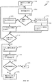
本開示の一側面は、埋め込み可能神経刺激装置の回路を制御し、電気刺激を標的領域に送達するために患者の体内の標的領域に近接して位置付け可能である複数の電極を有するそこに電気的に結合される埋め込み可能導線に電流を選択的にソースまたはシンクする方法に関する。方法は、第1の差動増幅器の所望の動作を識別することであって、第1の差動増幅器は、生体適合性筐体の密封してシールされた内部容積内に位置し、第1の差動増幅器は、電流を導線に選択的にソースし、電流を導線から選択的にシンクすることができる、ことと、第1の制御信号を生成することであって、第1の制御信号は、第1の差動増幅器に、電流を導線にソースすること、または電流を導線からシンクすることのいずれかを行わせる、ことと、第1の制御信号を第1の差動増幅器に提供することとを含む。 One aspect of the disclosure is that there are multiple electrodes that can be positioned close to the target area in the patient's body to control the circuit of the implantable nerve stimulator and deliver the electrical stimulus to the target area. It relates to a method of selectively sourcing or sinking a current into an implantable conductor that is coupled to the wire. The method is to identify the desired operation of the first differential amplifier, the first differential amplifier being located within the sealed and sealed internal volume of the biocompatible enclosure and the first. The differential amplifier can selectively source the current to the conductor and selectively sync the current from the conductor, and to generate a first control signal, the first control signal. Causes the first differential amplifier to either source the current to the conductor or sink the current from the conductor, and provides the first control signal to the first differential amplifier. Including to do.
方法のいくつかの実施形態では、第1の制御信号を生成することは、第1の差動増幅器の所望の動作が電流を導線にソースすべきか、または電流を導線からシンクすべきかを決定することを含むことができる。方法のいくつかの実施形態では、第1の制御信号を生成することは、電流を第1の差動増幅器からソースすべきか、または電流を第1の差動増幅器に選択的にシンクすべきかどうかを決定することを含むことができる。方法のいくつかの実施形態では、第1の制御信号を生成することは、電流を第1の差動増幅器からソースすべきであると決定される場合、仮想接地電圧を上回る電圧を有するように第1の制御信号を生成することを含むことができる。いくつかの実施形態では、制御信号を生成することはさらに、電流を第1の差動増幅器にシンクすべきであると決定される場合、仮想接地電圧未満の電圧を有するように第1の制御信号を生成することを含む。 In some embodiments of the method, generating a first control signal determines whether the desired operation of the first differential amplifier should source the current to the conductor or sink the current from the conductor. Can include that. In some embodiments of the method, whether generating the first control signal should source the current from the first differential amplifier or selectively sink the current into the first differential amplifier. Can include determining. In some embodiments of the method, generating the first control signal is to have a voltage above the virtual ground voltage if it is determined that the current should be sourced from the first differential amplifier. It can include generating a first control signal. In some embodiments, generating a control signal further controls the first control to have a voltage less than the virtual ground voltage if it is determined that the current should be synced to the first differential amplifier. Includes generating a signal.
いくつかの実施形態では、方法は、第2の差動増幅器の所望の動作を識別することを含み、第2の差動増幅器は、生体適合性筐体の密封してシールされた内部容積内に位置し、第2の差動増幅器は、電流を導線に選択的にソースし、電流を導線から選択的にシンクすることができる。いくつかの実施形態では、方法は、第2の制御信号を生成し、第2の差動増幅器に、電流を導線にソースするか、または電流を導線からシンクするかのいずれかを行わせることを含むことができ、いくつかの実施形態では、方法は、第2の制御信号を第2の差動増幅器に提供することを含むことができる。 In some embodiments, the method comprises identifying the desired operation of the second differential amplifier, which is within the sealed and sealed internal volume of the biocompatible enclosure. Located in, the second differential amplifier can selectively source the current to the conductor and selectively sink the current from the conductor. In some embodiments, the method is to generate a second control signal and have the second differential amplifier either source the current to the conductor or sink the current from the conductor. In some embodiments, the method can include providing a second control signal to a second differential amplifier.
いくつかの実施形態では、第1の制御信号が第1の差動増幅器に電流を導線にソースさせる場合、第2の信号は、第2の差動増幅器に電流を導線からシンクさせるために生成される。いくつかの実施形態では、第1の制御信号が第1の差動増幅器に電流を導線からシンクさせる場合、第2の信号は、第2の差動増幅器に電流を導線にソースさせるために生成される。いくつかの実施形態では、第1の差動増幅器は、電流を導線の複数の電極のうちの第1の少なくとも1つに選択的にソースし、電流を導線の複数の電極のうちの第1の少なくとも1つから選択的にシンクすることができ、第2の差動増幅器は、電流を導線の複数の電極のうちの第2の少なくとも1つに選択的にソースし、電流を導線の複数の電極のうちの第2の少なくとも1つから選択的にシンクすることができる。 In some embodiments, if the first control signal causes the first differential amplifier to source current to the conductor, the second signal is generated to cause the second differential amplifier to sink the current from the conductor. Will be done. In some embodiments, if the first control signal causes the first differential amplifier to sink the current from the conductor, the second signal is generated to cause the second differential amplifier to source the current to the conductor. Will be done. In some embodiments, the first differential amplifier selectively sources the current to at least one of the first of the plurality of electrodes of the conductor and the current to the first of the plurality of electrodes of the conductor. Can be selectively synced from at least one of the conductors, the second differential amplifier selectively sources the current to at least one of the second of the plurality of electrodes of the conductor and the current to the plurality of conductors. Can be selectively synced from at least one of the second electrodes of.
いくつかの実施形態では、導線の複数の電極のうちの第1の少なくとも1つおよび導線の複数の電極のうちの第2の少なくとも1つは、患者の体内の標的領域を通して回路を完成するように選択される。いくつかの実施形態では、患者の身体の標的領域は、仙骨組織を含む。いくつかの実施形態では、第1の差動増幅器および第2の差動増幅器は、電流をソースまたは電流をシンクし、1つまたはいくつかの電気パルスを生成することができる。いくつかの実施形態では、1つまたはいくつかの電気パルスは、電気パルスのパラメータを規定するパルスプログラムに従って生成される。いくつかの実施形態では、1つまたはいくつかの電気パルスは、単極であることができ、いくつかの実施形態では、1つまたはいくつかの電気パルスは、双極であることができる。 In some embodiments, at least one of the plurality of electrodes of the conductor and at least one of the second of the plurality of electrodes of the conductor complete the circuit through a target region within the patient's body. Is selected for. In some embodiments, the target area of the patient's body comprises sacral tissue. In some embodiments, the first differential amplifier and the second differential amplifier can source or sink current to generate one or several electrical pulses. In some embodiments, one or several electrical pulses are generated according to a pulse program that defines the parameters of the electrical pulse. In some embodiments, one or some electrical pulses can be unipolar, and in some embodiments, one or some electrical pulses can be bipolar.
本開示の一側面は、標的領域に近接して位置付け可能であり、そこに電気的に統合可能な複数の電極を備えている埋め込み可能導線を用いて1つ以上の電気パルスを患者の体内の標的領域に送達するための埋め込み可能神経刺激装置に関する。埋め込み可能神経刺激装置は、選択的に、電流を導線にソースし、電流を導線からシンクすることができる第1の差動増幅器と、選択的に、電流を導線にソースし、電流を導線からシンクすることができる第2の差動増幅器とを含むことができる、無ASIC電流ソース/シンク発生器を含む。埋め込み可能神経刺激装置は、第1の差動増幅器のために電流ソースまたはシンクのうちの一方を選択するための第1の電気信号および第2の差動増幅器のために電流ソースまたはシンクのうちの他方を選択するための第2の電気信号を生成することができる刺激コントローラを含む。 One aspect of the disclosure is that one or more electrical pulses can be placed within the patient's body using implantable conductors that can be positioned close to the target area and have multiple electrically integrated electrodes. Concers with implantable nerve stimulators for delivery to target areas. Implantable nerve stimulators are a first differential amplifier that can selectively source current to the conductor and sink the current from the conductor, and selectively source the current to the conductor and source the current from the conductor. Includes a non-ASIC current source / sink generator, which may include a second differential amplifier capable of sinking. The implantable nerve stimulator is of a first electrical signal for selecting one of the current sources or sinks for the first differential amplifier and of the current sources or sinks for the second differential amplifier. Includes a stimulus controller capable of generating a second electrical signal for selecting the other of the.
いくつかの実施形態では、第1の差動増幅器は、仮想接地に接続される反転入力と、第1の電流コマンドに接続される非反転入力とを含む。いくつかの実施形態では、第2の差動増幅器は、仮想接地に接続される反転入力と、第2の電流コマンドに接続される非反転入力とを含む。いくつかの実施形態では、仮想接地は、第1の電圧を第1の差動増幅器の反転入力に供給し、第1の電圧を第2の差動増幅器の反転入力に供給する。 In some embodiments, the first differential amplifier comprises an inverting input connected to virtual ground and a non-inverting input connected to a first current command. In some embodiments, the second differential amplifier includes an inverting input connected to virtual ground and a non-inverting input connected to a second current command. In some embodiments, virtual ground supplies a first voltage to the inverting input of the first differential amplifier and a first voltage to the inverting input of the second differential amplifier.
いくつかの実施形態では、第1の電流コマンドは、電流をソースするために第1の差動増幅器を選択する場合、供給される第1の電圧を上回る第2の電圧を供給し、第1の電流コマンドは、電流をシンクするために第1の差動増幅器を選択する場合、供給される第1の電圧未満の第2の電圧を供給する。いくつかの実施形態では、第2の電流コマンドは、電流をソースするために第2の差動増幅器を選択する場合、供給される第1の電圧を上回る第3の電圧を供給し、第2の電流コマンドは、電流をシンクするために第2の差動増幅器を選択する場合、供給される第1の電圧未満の第3の電圧を供給する。 In some embodiments, the first current command supplies a second voltage that exceeds the first voltage supplied when selecting the first differential amplifier to source the current, the first. The current command supplies a second voltage less than the first voltage supplied when selecting the first differential amplifier to sink the current. In some embodiments, the second current command supplies a third voltage that exceeds the first voltage supplied when selecting a second differential amplifier to source the current, and a second. The current command supplies a third voltage less than the first voltage supplied when selecting a second differential amplifier to sink the current.
本開示の適用可能性のさらなる分野は、本明細書の以降で提供される発明を実施するための形態から明白となるであろう。発明を実施するための形態および具体的例は、種々の実施形態を示すが、例証目的のみで意図され、必ずしも本開示の範囲を限定することを意図しないことを理解されたい。
本発明は、例えば、以下を提供する。
(項目1)
1つ以上の電気パルスを患者の体内の標的領域に送達するための埋め込み可能神経刺激装置システムであって、
複数の電極を備えている埋め込み可能導線であって、前記複数の電極は、前記導線の遠位端上に位置しており、前記電極は、患者の体内の標的領域に近接して位置付け可能であり、電気刺激を前記標的領域に提供する、埋め込み可能導線と、
前記導線の近位端に電気的に結合されている埋め込み可能パルス発生器と
を備え、
前記埋め込み可能パルス発生器は、
密封してシールされた内部容積を画定する生体適合性筐体と、
前記生体適合性筐体の前記密封してシールされた内部容積内に配置されている再充電可能電力供給源と、
前記生体適合性筐体の前記密封してシールされた内部容積内に配置されている回路と
を備え、
前記回路は、前記再充電可能電力供給源に電気的に結合され、1つ以上の電気パルスを生成するように構成され、前記回路は、電流を前記導線に選択的にソースし、電流を前記導線から選択的にシンクするように構成されている第1の差動増幅器を備えている、
埋め込み可能神経刺激装置システム。
(項目2)
前記回路は、電流を前記導線に選択的にソースし、電流を前記導線から選択的にシンクするように構成されている第2の差動増幅器をさらに備えている、項目1に記載の埋め込み可能神経刺激装置システム。
(項目3)
前記第2の差動増幅器は、前記第1の差動増幅器が、電流を前記導線上に位置している前記複数の電極のうちの少なくとも1つにソースするために選択されている場合、電流を前記導線上に位置している前記複数の電極のうちの少なくとも別の1つからシンクするために選択される、項目2に記載の埋め込み可能神経刺激装置システム。
(項目4)
前記第2の差動増幅器は、前記第1の差動増幅器が、電流を前記導線上に位置している前記複数の電極のうちの少なくとも1つからシンクするために選択されている場合、電流を前記導線上に位置している前記複数の電極のうちの少なくとも別の1つにソースするために選択される、項目3に記載の埋め込み可能神経刺激装置システム。
(項目5)
前記第1の差動増幅器は、電流コマンドに結合されている非反転入力を含み、前記電流コマンドは、第1の範囲内の電圧を前記非反転入力に供給するように構成され、前記第1の差動増幅器は、仮想接地に結合されている反転入力を含む、項目4に記載の埋め込み可能神経刺激装置システム。
(項目6)
供給される電圧の前記第1の範囲は、最大電圧および最小電圧を有し、前記第1の範囲の前記最大電圧と前記最小電圧との間の電圧の差異は、少なくとも5ボルトである、項目5に記載の埋め込み可能神経刺激装置システム。
(項目7)
前記仮想接地は、前記供給される電圧の前記最大電圧と前記最小電圧との間の接地電圧を備えている、項目6に記載の埋め込み可能神経刺激装置システム。
(項目8)
前記第1の差動増幅器の反転入力に結合されている仮想接地は、前記回路が定常状態で動作しているときの前記仮想接地の接地電圧と等しい前記反転入力における電圧を有する、項目7に記載の埋め込み可能神経刺激装置システム。
(項目9)
前記第1の差動増幅器は、前記第1の差動増幅器の非反転入力に印加される前記供給される電圧が前記仮想接地の接地電圧を上回る場合、電流をソースするために構成可能である、項目8に記載の埋め込み可能神経刺激装置システム。
(項目10)
前記第1の差動増幅器は、前記第1の差動増幅器の非反転入力に印加される前記供給される電圧が前記仮想接地の接地電圧未満である場合、電流をシンクするために構成可能である、項目9に記載の埋め込み可能神経刺激装置システム。
(項目11)
複数の電極を備えている埋め込み可能導線を用いて1つ以上の電気パルスを患者の体内の標的領域に送達するための埋め込み可能神経刺激装置であって、前記複数の電極は、前記標的領域に近接して位置付け可能であり、前記標的領域に電気的に統合可能であり、
前記埋め込み可能神経刺激装置は、
患者の体内に埋め込まれるように構成されている密封してシールされた内部容積を画定する生体適合性筐体と、
前記生体適合性筐体の前記密封してシールされた内部容積内に配置されている再充電可能バッテリと、
前記生体適合性筐体の前記密封してシールされた内部容積内に配置されている回路と
を備え、
前記回路は、前記再充電可能電力供給源に電気的に結合され、1つ以上の電気パルスを生成するように構成され、
前記回路は、
第1の電流制御モジュールと、
第2の電流制御モジュールと
を備え、
前記第1の電流制御モジュールおよび前記第2の電流制御モジュールの各々は、
非反転入力、反転入力、および出力を有する電流駆動差動増幅器と、
前記非反転入力に結合されている電流制御であって、前記電流制御は、第1の範囲内の電圧を前記非反転入力に供給するように構成され、前記第1の範囲は、最小電圧と最大電圧との間である、電流制御と、
前記反転入力に結合されている仮想接地であって、前記仮想接地は、前記最小電圧と前記最大電圧との間の接地電圧を有する、仮想接地と、
前記電流駆動差動増幅器の出力を前記導線に選択的に結合している負荷経路であって、前記負荷経路は、前記電流駆動差動増幅器の出力と前記導線との間に位置する感知抵抗器を備えている、負荷経路と
を備えている、埋め込み可能神経刺激装置。
(項目12)
前記第1および第2の電流制御モジュールのうちの少なくとも1つは、感知非反転入力、感知反転入力、および感知出力を備えている電流感知差動増幅器を備えている、項目11に記載の埋め込み可能神経刺激装置。
(項目13)
前記感知非反転入力は、第1の抵抗を有する第1の抵抗器を介して、前記感知抵抗器と前記電流駆動差動増幅器の出力との間で前記負荷経路に接続され、前記感知反転入力は、前記第1の抵抗を有する第2の抵抗器を介して、前記感知抵抗器と前記導線との間で前記負荷経路に接続されている、項目12に記載の埋め込み可能神経刺激装置。
(項目14)
前記感知非反転入力は、第2の抵抗を有する第3の抵抗器を介して、前記仮想接地に接続され、前記感知反転入力は、前記第2の抵抗を有する第4の抵抗器を介して、前記感知出力に接続されている、項目13に記載の埋め込み可能神経刺激装置。
(項目15)
前記第2の抵抗は、前記第1の抵抗の少なくとも2倍である、項目14に記載の埋め込み可能神経刺激装置。
(項目16)
前記第2の抵抗は、前記第1の抵抗の少なくとも10倍である、項目15に記載の埋め込み可能神経刺激装置。
(項目17)
前記感知抵抗器を横断する電圧降下を測定するように構成されている電圧センサをさらに備えている、項目14に記載の埋め込み可能神経刺激装置。
(項目18)
前記感知抵抗器を横断する電圧降下は、前記接地電圧と前記電流感知差動増幅器の出力との間の差異を決定することによって測定される、項目17に記載の埋め込み可能神経刺激装置。
(項目19)
前記第1の制御モジュールは、電流を前記導線に選択的にソースし、電流を前記導線から選択的にシンクするように構成されている、項目18に記載の埋め込み可能神経刺激装置。
(項目20)
前記第2の制御モジュールは、電流を前記導線に選択的にソースし、電流を前記導線から選択的にシンクするように構成されている、項目19に記載の埋め込み可能神経刺激装置。
(項目21)
前記電流駆動差動増幅器の反転入力に結合されている前記仮想接地は、前記第1の制御モジュールおよび前記第2の制御モジュールのうちの少なくとも1つが定常状態で動作しているとき、前記仮想接地の接地電圧と等しい前記反転入力における電圧を有する、項目20に記載の埋め込み可能神経刺激装置。
(項目22)
前記電流駆動差動増幅器は、前記電流駆動差動増幅器の非反転入力に印加される供給される電圧が前記仮想接地の接地電圧を上回る場合、電流をソースするために構成可能である、項目21に記載の埋め込み可能神経刺激装置。
(項目23)
前記電流駆動差動増幅器は、前記電流駆動差動増幅器の非反転入力に印加される前記供給される電圧が前記仮想接地の接地電圧未満である場合、電流をシンクするために構成可能である、項目22に記載の埋め込み可能神経刺激装置。
(項目24)
埋め込み可能導線に対して電流を選択的にソースまたはシンクするように埋め込み可能神経刺激装置の回路の作動方法であって、前記埋め込み可能導線は、前記回路に電気的に結合され、前記埋め込み可能導線は、電気刺激を前記標的領域に送達するために患者の体内の標的領域に近接して位置付け可能である複数の電極を備え、
前記方法は、
第1の差動増幅器の所望の動作を識別することであって、前記第1の差動増幅器は、生体適合性筐体の密封してシールされた内部容積内に位置し、前記第1の差動増幅器は、電流を導線に選択的にソースし、電流を前記導線から選択的にシンクするように構成されている、ことと、
第1の制御信号を生成することであって、前記第1の制御信号は、前記第1の差動増幅器に、電流を前記導線にソースすることまたは電流を前記導線からシンクすることのいずれかを行わせるように構成されている、ことと
前記第1の制御信号を前記第1の差動増幅器に提供することと
を含む、方法。
(項目25)
前記第1の制御信号を生成することは、前記第1の差動増幅器の所望の動作が電流を前記導線にソースすることであるか、または電流を前記導線からシンクすることであるかを決定することを含む、項目24に記載の方法。
(項目26)
前記第1の制御信号を生成することは、電流を前記第1の差動増幅器からソースすべきか、または電流を前記第1の差動増幅器に選択的にシンクすべきかを決定することを含む、項目25に記載の方法。
(項目27)
前記第1の制御信号を生成することは、電流を前記第1の差動増幅器からソースすべきことが決定された場合、仮想接地電圧を上回る電圧を有する前記第1の制御信号を生成することをさらに含む、項目26に記載の方法。
(項目28)
前記制御信号を生成することは、電流を前記第1の差動増幅器にシンクすべきことが決定された場合、仮想接地電圧未満の電圧を有する前記第1の制御信号を生成することをさらに含む、項目26に記載の方法。
(項目29)
第2の差動増幅器の所望の動作を識別することであって、前記第2の差動増幅器は、生体適合性筐体の密封してシールされた内部容積内に位置し、前記第2の差動増幅器は、電流を前記導線に選択的にソースし、電流を前記導線から選択的にシンクするように構成されている、ことと、
第2の制御信号を生成することであって、前記第2の制御信号は、前記第2の差動増幅器に、電流を前記導線にソースするか、または電流を前記導線からシンクするかのいずれかを行わせるように構成されている、ことと、
前記第2の制御信号を前記第2の差動増幅器に提供することと
をさらに含む、
項目24に記載の方法。
(項目30)
前記第1の制御信号が前記第1の差動増幅器に電流を前記導線にソースさせる場合、前記第2の信号は、前記第2の差動増幅器に電流を前記導線からシンクさせるために生成される、項目29に記載の方法。
(項目31)
前記第1の制御信号が前記第1の差動増幅器に電流を前記導線からシンクさせる場合、前記第2の信号は、前記第2の差動増幅器に電流を前記導線にソースさせるために生成される、項目29に記載の方法。
(項目32)
前記第1の差動増幅器は、電流を前記導線の前記複数の電極のうちの第1の少なくとも1つに選択的にソースし、電流を前記導線の前記複数の電極のうちの前記第1の少なくとも1つから選択的にシンクするように構成され、前記第2の差動増幅器は、電流を前記導線の前記複数の電極のうちの第2の少なくとも1つに選択的にソースし、電流を前記導線の前記複数の電極のうちの前記第2の少なくとも1つから選択的にシンクするように構成されている、項目29に記載の方法。
(項目33)
前記導線の前記複数の電極のうちの前記第1の少なくとも1つおよび前記導線の前記複数の電極のうちの前記第2の少なくとも1つは、前記患者の体内の標的領域を通して回路を完成するように選択される、項目32に記載の方法。
(項目34)
前記患者の身体の標的領域は、仙骨組織を備えている、項目33に記載の方法。
(項目35)
前記第1の差動増幅器および前記第2の差動増幅器は、電流をソースまたは電流をシンクし、1つまたはいくつかの電気パルスを生成するように構成されている、項目29に記載の方法。
(項目36)
前記1つまたはいくつかの電気パルスは、前記電気パルスのパラメータを規定するパルスプログラムに従って生成される、項目35に記載の方法。
(項目37)
前記1つまたはいくつかの電気パルスは、単極であることができる、項目36に記載の方法。
(項目38)
前記1つまたはいくつかの電気パルスは、双極であることができる、項目36に記載の方法。
(項目39)
埋め込み可能導線を用いて1つ以上の電気パルスを患者の体内の標的領域に送達するための埋め込み可能神経刺激装置であって、前記埋め込み可能導線は、前記標的領域に近接して位置付け可能であり、前記標的領域に電気的に統合可能な複数の電極を備え、
前記埋め込み可能導線は、
無ASIC電流ソース/シンク発生器であって、前記発生器は、
電流を前記導線に選択的にソースし、電流を前記導線から選択的にシンクするように構成されている第1の差動増幅器と、
電流を前記導線に選択的にソースし、電流を前記導線から選択的にシンクするように構成されている第2の差動増幅器と
を備えている、無ASIC電流ソース/シンク発生器と、
刺激コントローラと
を備え、
前記刺激コントローラは、
前記第1の差動増幅器のために、電流をソースすることまたはシンクすることのうちの一方を選択するための第1の電気信号を生成することと、
前記第2の差動増幅器のために、電流をソースすることまたはシンクすることのうちの他方を選択するための第2の電気信号を生成することと
を行うように構成されている、埋め込み可能神経刺激装置。
(項目40)
前記第1の差動増幅器は、仮想接地に接続されている反転入力および第1の電流コマンドに接続されている非反転入力を備え、前記第2の差動増幅器は、前記仮想接地に接続されている反転入力および第2の電流コマンドに接続されている非反転入力を備えている、項目39に記載の埋め込み可能神経刺激装置。
(項目41)
前記仮想接地は、第1の電圧を前記第1の差動増幅器の反転入力に供給し、前記第1の電圧を前記第2の差動増幅器の反転入力に供給する、項目40に記載の埋め込み可能神経刺激装置。
(項目42)
前記第1の電流コマンドは、電流をソースするために前記第1の差動増幅器を選択する場合、前記供給される第1の電圧を上回る第2の電圧を供給し、前記第1の電流コマンドは、電流をシンクするために前記第1の差動増幅器を選択する場合、前記供給される第1の電圧未満の第2の電圧を供給する、項目41に記載の埋め込み可能神経刺激装置。
(項目43)
前記第2の電流コマンドは、電流をソースするために前記第2の差動増幅器を選択する場合、前記供給される第1の電圧を上回る第3の電圧を供給し、前記第2の電流コマンドは、電流をシンクするために前記第2の差動増幅器を選択する場合、前記供給される第1の電圧未満の第3の電圧を供給する、項目42に記載の埋め込み可能神経刺激装置。
Further areas of applicability of the present disclosure will become apparent from the embodiments provided herein for carrying out the invention. It should be understood that the embodiments and specific examples for carrying out the invention show various embodiments, but are intended for illustrative purposes only and not necessarily to limit the scope of the present disclosure.
The present invention provides, for example,:
(Item 1)
An implantable neurostimulator system for delivering one or more electrical pulses to a target area within the patient's body.
An implantable conductor comprising a plurality of electrodes, wherein the plurality of electrodes are located on the distal end of the conductor, and the electrodes can be positioned close to a target area in the patient's body. With implantable conductors, which provide electrical stimulation to the target area,
With an implantable pulse generator electrically coupled to the proximal end of the conductor
With
The implantable pulse generator is
A biocompatible enclosure that seals and defines a sealed internal volume,
With the rechargeable power source located within the sealed and sealed internal volume of the biocompatible enclosure,
With circuits located within the sealed and sealed internal volume of the biocompatible enclosure
With
The circuit is configured to be electrically coupled to the rechargeable power source to generate one or more electrical pulses, the circuit selectively sources current to the conductor and the current to the conductor. It comprises a first differential amplifier that is configured to selectively sync from the conductor.
Implantable nerve stimulator system.
(Item 2)
The implantable implant according to
(Item 3)
The second differential amplifier is the current if the first differential amplifier is selected to source current to at least one of the plurality of electrodes located on the lead wire. 2. The implantable nerve stimulator system according to
(Item 4)
The second differential amplifier is the current if the first differential amplifier is selected to sink the current from at least one of the plurality of electrodes located on the lead wire. 3. The implantable nerve stimulator system according to
(Item 5)
The first differential amplifier includes a non-inverting input coupled to a current command, the current command being configured to supply a voltage within the first range to the non-inverting input, said first. The implantable nerve stimulator system of
(Item 6)
The first range of supplied voltages has a maximum voltage and a minimum voltage, and the voltage difference between the maximum voltage and the minimum voltage in the first range is at least 5 volts. 5. The implantable nerve stimulator system according to 5.
(Item 7)
The implantable nerve stimulator system according to item 6, wherein the virtual ground comprises a ground voltage between the maximum voltage and the minimum voltage of the supplied voltage.
(Item 8)
(Item 9)
The first differential amplifier can be configured to source current if the supplied voltage applied to the non-inverting input of the first differential amplifier exceeds the ground voltage of the virtual ground. , Item 8. Implantable nerve stimulator system.
(Item 10)
The first differential amplifier can be configured to sink current if the supplied voltage applied to the non-inverting input of the first differential amplifier is less than the ground voltage of the virtual ground. The implantable nerve stimulator system according to item 9.
(Item 11)
An implantable nerve stimulator for delivering one or more electrical pulses to a target region within a patient's body using implantable conductors comprising a plurality of electrodes, wherein the plurality of electrodes are located in the target region. It can be positioned in close proximity and can be electrically integrated into the target area.
The implantable nerve stimulator
A biocompatible enclosure that defines a sealed and sealed internal volume that is configured to be implanted in the patient's body,
With the rechargeable battery located within the sealed and sealed internal volume of the biocompatible enclosure,
With circuits located within the sealed and sealed internal volume of the biocompatible enclosure
With
The circuit is configured to be electrically coupled to the rechargeable power source to generate one or more electrical pulses.
The circuit
The first current control module and
With the second current control module
With
Each of the first current control module and the second current control module
With a current-driven differential amplifier with non-inverting inputs, inverting inputs, and outputs,
A current control coupled to the non-inverting input, wherein the current control is configured to supply a voltage within the first range to the non-inverting input, the first range being the minimum voltage. With current control, which is between the maximum voltage,
A virtual ground coupled to the inverting input, wherein the virtual ground has a ground voltage between the minimum voltage and the maximum voltage.
A load path that selectively couples the output of the current-driven differential amplifier to the conductor, which is a sensing resistor located between the output of the current-driven differential amplifier and the conductor. With load path and
An implantable nerve stimulator equipped with.
(Item 12)
11. The embedding of
(Item 13)
The sense-inverted input is connected to the load path between the sense resistor and the output of the current-driven differential amplifier via a first resistor having a first resistor, and the sense-inverted input. 12. The implantable nerve stimulator according to
(Item 14)
The sensing non-inverting input is connected to the virtual ground via a third resistor having a second resistor, and the sensing inverting input is via a fourth resistor having the second resistor. The implantable nerve stimulator according to item 13, which is connected to the sensing output.
(Item 15)
The implantable nerve stimulator according to item 14, wherein the second resistance is at least twice the first resistance.
(Item 16)
The implantable nerve stimulator according to
(Item 17)
14. The implantable nerve stimulator according to item 14, further comprising a voltage sensor configured to measure a voltage drop across the sense resistor.
(Item 18)
The implantable nerve stimulator according to item 17, wherein the voltage drop across the sense resistor is measured by determining the difference between the ground voltage and the output of the current sense differential amplifier.
(Item 19)
The implantable nerve stimulator according to
(Item 20)
19. The implantable nerve stimulator according to item 19, wherein the second control module is configured to selectively source current to the conductor and selectively sync the current from the conductor.
(Item 21)
The virtual ground coupled to the inverting input of the current-driven differential amplifier is said to be virtual ground when at least one of the first control module and the second control module is operating in a steady state. 20. The implantable nerve stimulator according to
(Item 22)
The current-driven differential amplifier can be configured to source current if the supplied voltage applied to the non-inverting input of the current-driven differential amplifier exceeds the ground voltage of the virtual ground. Implantable nerve stimulator described in.
(Item 23)
The current-driven differential amplifier can be configured to sink current if the supplied voltage applied to the non-inverting input of the current-driven differential amplifier is less than the ground voltage of the virtual ground. The implantable nerve stimulator according to
(Item 24)
A method of operating a circuit of an implantable nerve stimulator such that a current is selectively sourced or synced with respect to an implantable conductor, wherein the implantable conductor is electrically coupled to the circuit and the implantable conductor. Provided with multiple electrodes that can be positioned close to the target area within the patient's body to deliver electrical stimulation to the target area.
The method is
To identify the desired operation of the first differential amplifier, the first differential amplifier is located within a sealed and sealed internal volume of the biocompatible enclosure, said first. The differential amplifier is configured to selectively source current to a conductor and selectively sink current from said conductor.
To generate a first control signal, the first control signal either sources a current to the conductor or sinks the current from the conductor to the first differential amplifier. Is configured to do
To provide the first control signal to the first differential amplifier.
Including methods.
(Item 25)
Generating the first control signal determines whether the desired operation of the first differential amplifier is to source the current to the conductor or to sink the current from the conductor. 24. The method of item 24, comprising:
(Item 26)
Generating the first control signal includes determining whether the current should be sourced from the first differential amplifier or selectively synced to the first differential amplifier. The method according to item 25.
(Item 27)
Generating the first control signal is to generate the first control signal having a voltage above the virtual ground voltage when it is determined that the current should be sourced from the first differential amplifier. 26. The method of item 26.
(Item 28)
Generating the control signal further comprises generating the first control signal having a voltage less than the virtual ground voltage when it is determined that the current should be synced to the first differential amplifier. , Item 26.
(Item 29)
To identify the desired operation of the second differential amplifier, the second differential amplifier is located within the sealed and sealed internal volume of the biocompatible enclosure and the second differential amplifier. The differential amplifier is configured to selectively source current to the conductor and selectively sink current from the conductor.
To generate a second control signal, the second control signal either sources a current to the conductor or sinks the current from the conductor to the second differential amplifier. And that it is configured to do
To provide the second control signal to the second differential amplifier.
Including,
The method according to item 24.
(Item 30)
When the first control signal causes the first differential amplifier to source a current to the conductor, the second signal is generated to cause the second differential amplifier to sink the current from the conductor. 29, the method of item 29.
(Item 31)
When the first control signal causes the first differential amplifier to sink current from the conductor, the second signal is generated to cause the second differential amplifier to source current to the conductor. 29, the method of item 29.
(Item 32)
The first differential amplifier selectively sources current to at least one of the plurality of electrodes of the conductor and directs current to the first of the plurality of electrodes of the conductor. Configured to selectively sync from at least one, the second differential amplifier selectively sources current to at least one of the second of the plurality of electrodes of the conductor to direct current. 29. The method of item 29, which is configured to selectively sync from at least one of the second of the plurality of electrodes of the conductor.
(Item 33)
At least one of the first of the plurality of electrodes of the conductor and at least one of the second of the plurality of electrodes of the conductor complete the circuit through a target region within the patient's body. 32. The method of item 32, which is selected for.
(Item 34)
33. The method of item 33, wherein the target area of the patient's body comprises sacral tissue.
(Item 35)
29. The method of item 29, wherein the first differential amplifier and the second differential amplifier are configured to source or sink current to generate one or several electrical pulses. ..
(Item 36)
35. The method of item 35, wherein the one or several electrical pulses are generated according to a pulse program that defines the parameters of the electrical pulse.
(Item 37)
36. The method of item 36, wherein the one or several electrical pulses can be unipolar.
(Item 38)
36. The method of item 36, wherein the one or several electrical pulses can be bipolar.
(Item 39)
An implantable nerve stimulator for delivering one or more electrical pulses to a target region within a patient's body using implantable conductors, said implantable conductors that can be positioned close to the target region. The target region is provided with a plurality of electrodes that can be electrically integrated.
The embeddable conductor
No ASIC current source / sink generator, said generator
A first differential amplifier configured to selectively source current to the conductor and selectively sink current from the conductor.
With a second differential amplifier configured to selectively source current to the conductor and selectively sink current from the conductor.
With no ASIC current source / sink generator,
With a stimulus controller
With
The stimulus controller
Generating a first electrical signal to choose between source and sink current for the first differential amplifier.
For the second differential amplifier to generate a second electrical signal to select the other of source and sink current.
An implantable nerve stimulator that is configured to do.
(Item 40)
The first differential amplifier comprises an inverting input connected to virtual ground and a non-inverting input connected to a first current command, and the second differential amplifier is connected to the virtual ground. 39. The implantable nerve stimulator according to item 39, comprising an inverting input and a non-inverting input connected to a second current command.
(Item 41)
The embedding according to
(Item 42)
The first current command supplies a second voltage above the first supplied voltage when the first differential amplifier is selected to source the current, and the first current command. 41. The implantable nerve stimulator according to item 41, which supplies a second voltage less than the first supplied voltage when the first differential amplifier is selected to sink current.
(Item 43)
The second current command supplies a third voltage above the first supplied voltage when the second differential amplifier is selected to source the current, and the second current command. 42. The implantable nerve stimulator according to item 42, which supplies a third voltage below the first supplied voltage when the second differential amplifier is selected to sink current.
本発明は、神経刺激治療システムおよび関連デバイス、ならびにそのような治療システムの治療、埋め込み/設置、および構成の方法に関する。1つの特定の実施形態では、本発明は、過活動膀胱(「OAB」)を治療し、膀胱関連機能不全の症状を緩和するように構成される仙骨神経刺激治療システムに関する。しかしながら、本発明は、当業者によって理解されるであろうように、排便機能不全等の任意の種々の神経調節用途、疼痛または運動もしくは情動障害等の他の適応症の治療にも利用され得ることが理解されるであろう。 The present invention relates to neurostimulation treatment systems and related devices, as well as methods of treatment, implantation / installation, and configuration of such treatment systems. In one particular embodiment, the invention relates to a sacral nerve stimulation therapy system configured to treat overactive bladder (“OAB”) and alleviate the symptoms of bladder-related dysfunction. However, the present invention may also be utilized in any variety of neuromodulatory applications such as defecation dysfunction and in the treatment of other indications such as pain or motor or emotional disorders, as will be appreciated by those skilled in the art. Will be understood.
(I.神経刺激適応症)
本明細書に説明されるもののうちのいずれか等の神経刺激(または以降で同義的に使用され得るような神経調節)治療システムは、急性疼痛障害、運動障害、情動障害、ならびに膀胱関連機能不全等の種々の病気および関連症状を治療するために使用されることができる。神経刺激によって治療され得る疼痛障害の例は、脊椎手術後疼痛症候群、反射性交感神経性ジストロフィまたは複合性局所疼痛症候群、灼熱痛、クモ膜炎、および末梢神経障害を含む。運動障害は、筋麻痺、振戦、ジストニア、およびパーキンソン病を含む。情動障害は、うつ病、強迫性障害、群発頭痛、トゥレット障害、およびあるタイプの慢性疼痛を含む。膀胱関連機能不全は、OAB、切迫尿失禁、切迫頻尿、および尿閉を含むが、それらに限定されない。OABは、単独で、または組み合わせて、切迫尿失禁および切迫頻尿を含むことができる。切迫尿失禁は、突然の強い尿意(切迫性)に関連付けられる失禁である。切迫頻尿は、多くの場合、非常に少量の排尿をもたらす(頻尿)、頻繁で多くの場合は制御不能な尿意切迫感(切迫性)である。尿閉は、膀胱を空にすることができない状態である。神経刺激治療は、その状態もしくは関連症状に関連付けられる感覚および/または運動制御に関する標的神経組織の神経刺激を達成することによって、特定の状態に対処するように構成されることができる。
(I. Nerve stimulation indication)
Neurostimulatory (or neuromodulatory) therapeutic systems, such as those described herein, are acute pain disorders, movement disorders, emotional disorders, and bladder-related dysfunction. It can be used to treat various diseases and related symptoms such as. Examples of pain disorders that can be treated by neurostimulation include post-spine pain syndrome, reflex sympathetic dystrophy or complex regional pain syndrome, burning pain, arachnoiditis, and peripheral neuropathy. Movement disorders include muscle paralysis, tremor, dystonia, and Parkinson's disease. Affect disorders include depression, obsessive-compulsive disorder, cluster headache, Tourette's disorder, and certain types of chronic pain. Bladder-related dysfunction includes, but is not limited to, OAB, impending urinary incontinence, impending pollakiuria, and urinary retention. OAB can include imminent urinary incontinence and impending pollakiuria alone or in combination. Imminent urinary incontinence is incontinence associated with sudden and strong urge to urinate (urgency). Frequent urination is often resulting in very small amounts of urination (frequent urination), frequent and often uncontrollable urinary urgency (urgency). Urinary retention is a condition in which the bladder cannot be emptied. Nerve stimulation therapy can be configured to address a particular condition by achieving neural stimulation of the target nervous tissue with respect to sensory and / or motor control associated with that condition or associated symptom.
一側面では、本明細書に説明される方法およびシステムは、特に、排尿および排便機能不全の治療に適している。これらの状態は、歴史的に、医学界による認識が不足しており、有意な評価を受けていない。OABは、最も一般的な排尿機能不全のうちの1つである。それは、切迫頻尿、夜間頻尿、および切迫尿失禁を含む煩わしい排尿症状の存在によって特徴付けられる、複合的状態である。約3,300万人の米国人が、OABに悩まされていると推定される。成人人口のうち、全男性の約30%および全女性の40%が、OAB症状を抱えて生きている。 On the one hand, the methods and systems described herein are particularly suitable for the treatment of micturition and defecation dysfunction. Historically, these conditions have been poorly recognized by the medical community and have not received significant evaluation. OAB is one of the most common urinary dysfunctions. It is a complex condition characterized by the presence of annoying micturition symptoms, including impending pollakiuria, nocturia, and impending urinary incontinence. It is estimated that about 33 million Americans are suffering from OAB. Of the adult population, about 30% of all men and 40% of all women live with OAB symptoms.
OAB症状は、患者の心理社会的機能および生活の質に有意な悪影響を及ぼし得る。OABを患う人々は、多くの場合、活動を制限し、および/または対処方略を立てている。さらに、OABは、個人、その家族、および医療機関に有意な財政的負担を課している。共存症状態の有病率も、OABを患う患者では、一般人口より有意に高い。共存症は、転倒および骨折、尿路感染症、皮膚感染症、外陰腟炎、心血管疾患、ならびに中枢神経系病理を含み得る。慢性便秘、便失禁、および重複慢性便秘が、OABを患う患者では、より頻繁に起こる。 OAB symptoms can have a significant adverse effect on a patient's psychosocial function and quality of life. People with OAB often have restricted activity and / or coping strategies. In addition, OAB imposes a significant financial burden on individuals, their families, and medical institutions. The prevalence of comorbidities is also significantly higher in patients with OAB than in the general population. Comorbidities can include falls and fractures, urinary tract infections, skin infections, genital vaginal inflammation, cardiovascular disease, and central nervous system pathology. Chronic constipation, fecal incontinence, and multiple chronic constipation occur more frequently in patients with OAB.
OABの従来の治療は、概して、第1の対策過程として、生活習慣の修正を含む。生活習慣の修正は、食事からの膀胱刺激物(カフェイン等)の排除、流体摂取量の管理、減量、禁煙、および排泄の規則性の管理を含む。挙動修正は、排尿習慣の変更(膀胱訓練および排尿遅延等)、尿道括約筋の強度および制御を向上させるための骨盤底筋の訓練、切迫感抑制のためのバイオフィードバックおよび技法を含む。薬剤は、OABのための第2段階治療と見なされる。これらは、抗コリン作用薬剤(経口、経皮パッチ、およびゲル)ならびに経口ベータ−3アドレナリン作動薬を含む。しかしながら、抗コリン作用薬は、頻繁に、口渇、便秘、尿閉、視力障害、眠気、および錯乱を含む、煩わしい全身性副作用に関連付けられる。研究は、50%を上回る患者が、利点の欠如、有害事象、または費用に起因して、90日以内に抗コリン作用薬の使用を停止することを見出している。 Conventional treatment of OAB generally involves lifestyle modification as a first countermeasure process. Lifestyle modifications include elimination of bladder irritants (such as caffeine) from the diet, control of fluid intake, weight loss, quitting, and control of excretion regularity. Behavioral modifications include changes in micturition habits (such as bladder training and delayed micturition), training of the pelvic floor muscles to improve urethral sphincter strength and control, and biofeedback and techniques for suppressing urgency. The drug is considered a second-stage treatment for OAB. These include anticholinergic agents (oral, transdermal patches, and gels) and oral beta-3 adrenergic agonists. However, anticholinergic agents are often associated with annoying systemic side effects, including dry mouth, constipation, urinary retention, blurred vision, drowsiness, and confusion. Studies have found that over 50% of patients stop using anticholinergic agents within 90 days due to lack of benefit, adverse events, or cost.
これらのアプローチが失敗すると、米国泌尿器科学会によって提案される第3段階治療選択肢は、ボツリヌス毒素(BoNT−A)の排尿筋内(膀胱平滑筋)注射、経皮的脛骨神経刺激(PTNS)、および仙骨神経刺激(SNM)を含む。BoNT−A(Botox(登録商標))は、膀胱鏡誘導下で一連の排尿筋内注射を介して投与されるが、Botoxの反復注射が、概して、効果を維持するために4〜12ヶ月毎に要求され、Botoxは、望ましくないことに、尿閉をもたらし得る。いくつかの無作為化対照研究は、OAB患者におけるBoNT−Aのある程度の有効性を示しているが、OABに対するBoNT−Aの長期安全性および有効性は、大部分が未知である。 If these approaches fail, the third-stage treatment options proposed by the American Urological Society are intra-detrusor (bladder smooth muscle) injection of botulinum toxin (BoNT-A), percutaneous tibial nerve stimulation (PTNS), And includes sacral nerve stimulation (SNM). BoNT-A (Botox®) is administered via a series of intramuscular injections of urinary fluid under cystoscopic guidance, with repeated injections of Botox generally every 4-12 months to maintain efficacy. Required, Botox can, undesirably, result in urinary retention. Although some randomized controlled studies have shown some efficacy of BoNT-A in OAB patients, the long-term safety and efficacy of BoNT-A against OAB is largely unknown.
典型的には、上記アプローチが無効であることが判明するときに考慮される、代替的治療方法は、泌尿器系に関する神経の神経刺激である。そのような神経刺激方法は、PTNSおよびSNMを含む。PTNS療法は、12週間の期間にわたる毎週30分のセッションから成り、各セッションは、ハンドヘルド刺激装置から脛骨神経を介して仙骨神経叢に送達される電気刺激を使用する。良好に応答し、治療を継続する患者に対して、典型的には、3〜4週間毎の継続的セッションが、症状軽減を維持するために必要とされる。患者が治療スケジュールに準拠することができない場合、有効性を低下させる潜在性がある。PTNSの有効性は、いくつかの無作為化対照研究において実証されているが、PTNSの長期安全性および有効性は、現時点では比較的未知である。 Typically, an alternative treatment method considered when the above approach turns out to be ineffective is nerve stimulation of the nerves associated with the urinary system. Such nerve stimulation methods include PTNS and SNM. PTNS therapy consists of 30-minute weekly sessions over a 12-week period, each session using electrical stimulation delivered from a handheld stimulator to the sacral plexus via the tibial nerve. For patients who respond well and continue treatment, continuous sessions every 3-4 weeks are typically required to maintain symptom relief. If the patient is unable to comply with the treatment schedule, it has the potential to reduce efficacy. Although the efficacy of PTNS has been demonstrated in several randomized controlled studies, the long-term safety and efficacy of PTNS is relatively unknown at this time.
(II.仙骨神経調節)
SNMは、切迫尿失禁、切迫頻尿、および非閉塞性尿閉の管理のための安全、効果的、可逆的、かつ長期継続的な治療選択肢を提供する確立された療法である。SNM療法は、下背に位置する仙骨神経を刺激するために、弱電気パルスの使用を伴う。電極は、電極導線を仙骨の対応する孔の中に挿入することによって、仙骨神経に隣接して、通常、S3レベルに設置される。電極は、皮下に挿入され、後に、本明細書では「埋め込み可能神経刺激装置」または「神経刺激装置」とも称される、埋め込み可能パルス発生器(IPG)に取り付けられる。切迫尿失禁および切迫頻尿の両方の患者のために、5年の耐久性を含む、OABの治療のためのSNMの安全性ならびに有効性が、複数の研究によって支持され、十分に証明されている。SNMは、より保守的治療に失敗した患者、またはその候補ではない患者における慢性便失禁を治療するためにも是認されている。
(II. Sacral nerve regulation)
SNM is an established therapy that provides safe, effective, reversible, and long-term continuous treatment options for the management of impending urinary incontinence, impending pollakiuria, and non-obstructive urinary retention. SNM therapy involves the use of weak electrical pulses to stimulate the sacral nerve located in the lower back. Electrodes are usually placed at the S3 level adjacent to the sacral nerve by inserting electrode leads into the corresponding holes in the sacrum. The electrodes are inserted subcutaneously and later attached to an implantable pulse generator (IPG), also referred to herein as an "implantable nerve stimulator" or "nerve stimulator". For patients with both impending incontinence and impending pollakiuria, the safety and efficacy of SNM for the treatment of OAB, including 5-year endurance, has been supported and well documented by multiple studies. There is. SNM is also endorsed to treat chronic fecal incontinence in patients who have failed more conservative treatment or are not candidates.
(A.仙骨神経調節システムの埋め込み)
現在、SNM資格は、試験段階を油脂、成功した場合、恒久的埋め込みが続く。試験段階は、療法が効果的であるかどうかを患者が評価することを可能にされる試験刺激期間である。典型的には、試験刺激を行うために利用される、2つの技法がある。第1は、経皮的神経評価(PNE)と称される通院ベースの手技であり、他方は、段階的試験である。
(A. Implantation of the sacral nerve regulation system)
Currently, SNM qualifications are oiled in the testing phase and, if successful, are followed by permanent implantation. The study phase is a study stimulation period that allows the patient to assess whether the therapy is effective. Typically, there are two techniques used to perform test stimuli. The first is an outpatient-based procedure called percutaneous nerve evaluation (PNE), and the other is a step-by-step study.
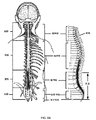
PNEでは、孔針が、典型的には、通常はS3レベルにおいて、最適刺激場所を識別し、仙骨神経の完全性を評価するために最初に使用される。運動および感覚反応が、以下の表1に説明されるように、正しい針設置を検証するために使用される。一時的刺激導線(単極電極)が、次いで、局所麻酔下で仙骨神経の近傍に設置される。この手技は、蛍光透視法を伴わずに、診療室環境で行われることができる。一時的導線は、次いで、試験段階中に患者の皮膚上にテープで貼り付けられた外部パルス発生器(EPG)に接続される。刺激レベルは、特定の患者のための最適快適性レベルを提供するために調節されることができる。患者は、任意の症状改善があるかどうかを確認するために、3〜7日間、その排尿を監視するであろう。PNEの利点は、それが局所麻酔を使用して医師の診療室で行われることができる無切開手技であることである。不利点は、一時的導線が定位置にしっかりと固定されず、物理的活動とともに神経から離れ、それによって療法の失敗を生じさせる傾向を有することである。患者がこの予備試験に失敗する場合、医師は、以下に説明されるような段階的試験を依然として推奨し得る。PNE試験が陽性である場合、一時的試験的導線が、除去され、恒久的四極歯付き導線が、全身麻酔下でIPGとともに埋め込まれる。 In PNE, a puncture needle is typically used first, typically at the S3 level, to identify the optimal stimulation site and assess the integrity of the sacral nerve. Motor and sensory responses are used to verify correct needle placement, as described in Table 1 below. A temporary stimulus lead (unipolar electrode) is then placed near the sacral nerve under local anesthesia. This procedure can be performed in a doctor's office environment without fluorescence perspective. The temporary leads are then connected to an external pulse generator (EPG) taped onto the patient's skin during the test phase. Stimulation levels can be adjusted to provide optimal comfort levels for a particular patient. Patients will monitor their urination for 3-7 days to see if there is any improvement in symptoms. The advantage of PNE is that it is an incision-free procedure that can be performed in a doctor's office using local anesthesia. The disadvantage is that the temporary conductors are not firmly fixed in place and tend to move away from the nerve with physical activity, thereby causing treatment failure. If the patient fails this preliminary study, the physician may still recommend a step-by-step study as described below. If the PNE test is positive, the temporary test lead is removed and a permanent quadrupole toothed lead is implanted with the IPG under general anesthesia.
段階的試験は、最初から、患者の中に恒久的四極歯付き刺激導線の埋め込みを伴う。それは、神経および最適刺激場所を識別するための孔針の使用も要求する。導線は、S3仙骨神経近傍に埋め込まれ、導線延長部を介して、EPGに接続される。この手技は、手術室内で、蛍光透視誘導下かつ局所または全身麻酔下で行われる。EPGは、患者のための最適快適性レベルを提供するように調節され、患者は、最大2週間の間、その排尿を監視する。患者が有意義な症状改善を得る場合、患者は、図1および3Aに示されるような、典型的には臀部上方領域内の全身麻酔下でのIPGの恒久的埋め込みのための好適な候補と見なされる。 From the beginning, the step-by-step study involves implantation of a permanent quadrupole toothed stimulus conductor in the patient. It also requires the use of pore needles to identify nerves and optimal stimulation sites. The conductor is implanted near the S3 sacral nerve and is connected to the EPG via the conductor extension. This procedure is performed in the operating room under fluoroscopy guidance and under local or general anesthesia. The EPG is adjusted to provide the optimum level of comfort for the patient, who monitors their urination for up to 2 weeks. If the patient obtains significant symptom improvement, the patient is considered a good candidate for permanent implantation of IPG under general anesthesia, typically within the upper buttock region, as shown in FIGS. 1 and 3A. Is done.

排尿機能不全のSNM治療のための転帰の測定に対して、排尿機能不全適応症(例えば、切迫尿失禁、切迫頻尿、および非閉塞性尿閉)が、特有の一次排尿日誌変数によって評価される。療法転帰は、これらの同一変数を使用して測定される。SNM療法は、最小50%改善が、ベースラインと比較して、一次排尿日誌変数のうちのいずれかで生じる場合に、成功と見なされる。切迫尿失禁患者に対して、これらの排尿日誌変数は、1日あたりの漏れエピソードの回数、1日あたりの大量の漏れエピソードの回数、および1日あたりの使用されるパッドの枚数を含み得る。切迫頻尿を患う患者に対して、一次排尿日誌変数は、1日あたりの排尿回数、排尿あたりの排尿量、および各排尿前に経験される尿意切迫度を含み得る。尿閉を患う患者に対して、一次排尿日誌変数は、導尿あたりの導尿量および1日あたりの導尿の回数を含み得る。 For measuring outcomes for the treatment of SNM of micturition dysfunction, micturition dysfunction indications (eg, impending urinary incontinence, impending pollakiuria, and non-obstructive urinary retention) are assessed by specific primary micturition variables. NS. Therapeutic outcomes are measured using these identical variables. SNM therapy is considered successful if a minimum 50% improvement occurs in any of the primary micturition diary variables compared to baseline. For patients with impending incontinence, these micturition variables may include the number of leaked episodes per day, the number of massive leaked episodes per day, and the number of pads used per day. For patients with impending pollakiuria, the primary micturition diary variables may include the number of micturitions per day, the volume of micturition per micturition, and the degree of urgency experienced prior to each micturition. For patients with urinary retention, the primary micturition diary variables may include the amount of urinary catheterization per urinary catheterization and the number of urinary catheterizations per day.
SNMの作用機序は、多因子性であり、いくつかの異なるレベルで神経軸に影響を及ぼす。OABを患う患者では、陰部求心性神経は、異常排尿反射の求心脚を阻止することによって膀胱蓄尿を助長する抑制反射を活性化することができると考えられる。これは、橋排尿中枢への入力を遮断し、それによって、正常排尿パターンに干渉せずに、不随意の排尿筋収縮を制限する。尿閉を患う患者に対して、SNMは、骨盤臓器から始まり脊髄の中に延びる陰部神経求心性神経を活性化すると考えられる。脊髄レベルで、これらの求心性神経は、過度の防御反射を抑制し、したがって、尿閉を患う患者の症状を緩和することによって、排尿反射を引き起こし得るので、正常排尿が、促進され得る。便失禁を患う患者では、SNMは、結腸推進活動を阻止し、内肛門括約筋を活性化する、陰部求心性体性線維を刺激し、ひいては、便失禁患者の症状を改善すると仮定される。本発明は、OABまたは膀胱関連機能不全の治療において治療効果を提供するように、標的神経組織の神経活動を妨害、阻止、または防止する様式で、神経刺激を標的神経組織に送達するように適合されるシステムに関する。一側面では、システムは、送達された神経刺激によって、OABまたは膀胱関連機能不全に関連付けられる筋肉の運動制御を誘発することなく、神経刺激による治療効果を提供するように適合される。別の側面では、システムは、感覚異常および/または神経筋応答を誘発する閾値を下回る、閾値下神経刺激の送達による、そのような治療効果を提供するように、もしくは閾値より下のレベルで療法を送達するために神経刺激の調節を可能にするように適合される。 The mechanism of action of SNM is multifactorial and affects the neural axis at several different levels. In patients with OAB, the pudendal afferent nerves may be able to activate the suppressive reflex that promotes bladder urinary storage by blocking the afferent leg of the abnormal micturition reflex. It blocks input to the pontine detrusor center, thereby limiting involuntary detrusor contractions without interfering with normal detrusor patterns. For patients suffering from urinary retention, SNM is thought to activate the pudendal afferent nerves that begin in the pelvic organs and extend into the spinal cord. At the spinal cord level, these afferent nerves can induce the micturition reflex by suppressing excessive defensive reflexes and thus alleviating the symptoms of patients suffering from urinary retention, thus facilitating normal micturition. In patients suffering from fecal incontinence, SNM is postulated to stimulate pudendal afferent somatic fibers that block colonic propulsion and activate the internal anal sphincter, thus improving the symptoms of fecal incontinence patients. The present invention is adapted to deliver neural stimuli to the target neural tissue in a manner that interferes with, blocks, or prevents neural activity in the target neural tissue to provide a therapeutic effect in the treatment of OAB or bladder-related dysfunction. Regarding the system to be done. On one side, the system is adapted to provide therapeutic effects by neural stimulation without inducing motor control of the muscles associated with OAB or bladder-related dysfunction by the delivered neural stimulation. In another aspect, the system provides such a therapeutic effect by delivery of subthreshold nerve stimuli below the threshold that elicits sensory abnormalities and / or neuromuscular responses, or at levels below the threshold. Is adapted to allow the regulation of nerve stimulation to deliver.
(B.EMGを伴う神経刺激導線の位置付け)
従来のアプローチは、膀胱関連機能不全の治療において有効性を示しているが、神経刺激導線の位置付けおよび導線の試験的位置と恒久的埋め込み位置との間の一貫性を向上させる必要が存在する。神経刺激は、1つ以上の神経刺激電極を介して、パルス発生器から特定の神経もしくは標的領域に治療用刺激を一貫して送達することに依拠する。神経刺激電極は、患者組織内に形成されるトンネルを通して前進させられることができる、埋め込み可能導線の遠位端上に提供される。埋め込み可能神経刺激システムは、患者に大幅な自由度および移動性を提供するが、そのようなシステムの神経刺激電極が外科的に埋め込まれる前に、それらを調節することがより容易であり得る。医師は、IPGを埋め込む前に、患者が所望の運動および/または感覚反応を有することを確認することが望ましい。少なくともいくつかの治療(少なくともいくつかの形態の排尿および/または排便機能不全の治療を含む)に対して、適切な運動反応の実証は、感覚反応が要求されないことも、利用可能でないこともあるが(例えば、患者が全身麻酔下にある)、正確かつ客観的な導線設置のために高度に有益であり得る。
(B. Positioning of nerve stimulation conductor with EMG)
Although conventional approaches have shown efficacy in the treatment of bladder-related dysfunction, there is a need to improve the positioning of nerve-stimulating leads and the consistency between experimental and permanent implantation positions of the leads. Nerve stimulation relies on consistently delivering a therapeutic stimulus from a pulse generator to a particular nerve or target area via one or more nerve stimulation electrodes. Nerve stimulation electrodes are provided on the distal end of implantable leads that can be advanced through tunnels formed within the patient's tissue. Implantable neural stimulation systems provide patients with greater freedom and mobility, but it may be easier to adjust the neural stimulation electrodes of such systems before they are surgically implanted. Physicians should ensure that the patient has the desired motor and / or sensory response prior to implanting the IPG. Demonstration of an appropriate motor response for at least some treatments, including treatment of at least some forms of micturition and / or defecation dysfunction, may not require a sensory response or may not be available. However (eg, the patient is under general anesthesia) can be highly beneficial for accurate and objective lead placement.
特定の神経に十分に近接した神経刺激電極および埋め込み可能導線の設置ならびに較正は、治療の有効性のために有益であり得る。故に、本開示の側面および実施形態は、神経刺激電極設置の正確度ならびに精度を補助し、精緻化することを対象とする。さらに、本開示の側面および実施形態は、埋め込み式神経刺激電極を通して実装される刺激プログラムの治療用治療信号パラメータを設定するためのプロトコルを補助し、精緻化することを対象とする。 The placement and calibration of nerve stimulation electrodes and implantable leads in close proximity to a particular nerve can be beneficial for therapeutic efficacy. Therefore, aspects and embodiments of the present disclosure are intended to assist and refine the accuracy and accuracy of neurostimulation electrode placement. In addition, aspects and embodiments of the present disclosure are intended to assist and refine protocols for setting therapeutic therapeutic signal parameters for stimulation programs implemented through implantable nerve stimulation electrodes.
恒久的デバイスの埋め込みに先立って、患者は、治療に対する潜在的反応を推定するために、初期試験段階を受け得る。上で議論されるように、PNEは、患者による主観的感覚反応に従って適切な仙骨神経を識別するために試験針を使用して、局所麻酔下で行われ得る。他の試験手技は、四極歯付き導線が、患者が症状頻度の十分な減少を示すかどうかを決定する試験段階のために埋め込まれ、適切である場合、神経調節デバイスの恒久的な外科的埋め込みに進む2段階外科的手技を伴うことができる。試験段階および恒久的埋め込みに対して、導線設置の場所の決定は、患者または医師の一方もしくは両方による主観的定質的分析に依存し得る。 Prior to implantation of the permanent device, the patient may undergo an initial trial phase to estimate the potential response to treatment. As discussed above, PNE can be performed under local anesthesia using a test needle to identify the appropriate sacral nerve according to the patient's subjective sensory response. Other test procedures include permanent surgical implantation of neuromodulatory devices, where quadrupole toothed leads are implanted for the study phase to determine if the patient exhibits a sufficient reduction in symptom frequency and, if appropriate. Can be accompanied by a two-step surgical procedure that proceeds to. For study stages and permanent implantation, the location of conductor placement may depend on subjective qualitative analysis by one or both of the patient and physician.
例示的実施形態では、埋め込み可能導線および神経刺激電極が所望の場所または正しい場所に位置するかどうかの決定は、表面筋電図検査としても公知である、筋電図検査(「EMG」)の使用を通して達成されることができる。EMGは、筋肉によって生成される電気活動を評価および記録するためにEMGシステムまたはモジュールを使用する技法であり、筋電図と呼ばれる記録を生成する。EMGは、筋肉細胞が電気的または神経学的に活性化されるときにそれらの細胞によって生成される電位を検出する。信号は、活性化レベルまたは動員順序を検出するために分析されることができる。EMGは、患者の皮膚表面を通して筋肉内で、標的筋肉の近傍で患者内に配置される電極を通して、または、外部および内部構造の組み合わせを使用して行われることができる。筋肉または神経が、電極によって刺激されているとき、EMGは、関連筋肉が刺激に反応して活性化されているかどうか(すなわち、筋肉が完全に収縮する、部分的に収縮する、または収縮しないかどうか)を決定するために使用されることができる。故に、筋肉の活性化の程度は、埋め込み可能導線または神経刺激電極が患者における所望の場所もしくは正しい場所に位置するかどうかを示すことができる。さらに、筋肉の活性化の程度は、神経刺激電極が、患者における治療計画に影響を及ぼすために十分な強度、振幅、周波数、または持続時間の刺激を提供しているかどうかを示すことができる。したがって、EMGの使用は、埋め込み可能導線および神経刺激電極の設置を標準化し、患者感覚反応の主観的査定を低減させる客観的かつ定量的な手段を提供する。 In an exemplary embodiment, the determination of whether implantable leads and nerve stimulation electrodes are located in the desired or correct location is also known as surface electromyography, of electromyography (“EMG”). Can be achieved through use. EMG is a technique that uses an EMG system or module to evaluate and record the electrical activity produced by muscles and produces a record called an electromyogram. EMG detects the potential generated by muscle cells as they are electrically or neurologically activated. The signal can be analyzed to detect activation levels or recruitment sequences. EMG can be performed intramuscularly through the patient's skin surface, through electrodes placed within the patient in the vicinity of the target muscle, or using a combination of external and internal structures. When a muscle or nerve is stimulated by an electrode, the EMG asks whether the associated muscle is activated in response to the stimulus (ie, the muscle contracts completely, partially, or does not contract). Can be used to determine). Therefore, the degree of muscle activation can indicate whether implantable leads or nerve stimulation electrodes are located in the desired or correct location in the patient. In addition, the degree of muscle activation can indicate whether the neural stimulation electrodes provide sufficient intensity, amplitude, frequency, or duration of stimulation to influence the treatment regimen in the patient. Therefore, the use of EMG provides an objective and quantitative means of standardizing the placement of implantable leads and neurostimulating electrodes and reducing the subjective assessment of patient sensory responses.
いくつかのアプローチでは、位置調整手技は、随意に、患者からの感覚異常または疼痛ベースの主観的反応に部分的に基づき得る。対照的に、EMGは、測定可能な個別的な筋肉反応を誘起する。治療の有効性が、多くの場合、標的組織場所における神経刺激電極の精密な設置と神経刺激療法の一貫した反復可能送達とに依拠するので、客観的EMG測定の使用は、SNM治療の有用性および成功を実質的に向上させることができる。測定可能筋肉反応は、標的筋肉の刺激に応じた部分的または完全筋肉収縮であり得、それは、表1に示されるもの等の観察可能運動反応の誘起を下回る反応を含む。加えて、神経刺激導線が恒久的埋め込み式システムで使用するために埋め込まれたままであることを可能にする試験的システムを利用することによって、恒久的埋め込み式システムの有効性および転帰は、試験的期間の結果とより一致し、それは、向上した患者転帰にさらにつながる。 In some approaches, the alignment procedure can optionally be based in part on a paresthesias or pain-based subjective response from the patient. In contrast, EMG induces measurable individual muscle responses. The use of objective EMG measurements is useful for SNM treatment, as the effectiveness of treatment often depends on the precise placement of nerve stimulation electrodes at the target tissue location and the consistent and repeatable delivery of nerve stimulation therapy. And can substantially improve success. The measurable muscle response can be partial or complete muscle contraction in response to stimulation of the target muscle, including responses below the induction of observable motor responses such as those shown in Table 1. In addition, the effectiveness and outcome of the permanent implantable system is experimental by utilizing a pilot system that allows the nerve stimulation leads to remain implanted for use in the permanent implantable system. More consistent with the duration results, which further leads to improved patient outcomes.
(C.例示的実施形態)
図1は、本発明の側面による、試験的神経刺激システム200および恒久的埋め込み式神経刺激システム100の両方を含む、例示的神経刺激システムを概略的に図示する。EPG80およびIPG10の各々は、臨床医用プログラム装置(CP)60および患者遠隔装置70との適合性があり、無線で通信し、臨床医用プログラム装置60および患者遠隔装置70は、試験的神経刺激システム200および/または試験成功後の恒久的埋め込み式システム100を位置付けることおよび/またはプログラムすることにおいて使用される。上で議論されるように、臨床医用プログラム装置は、導線設置、プログラミング、再プログラミング、刺激制御、および/またはパラメータ設定に役立つように、特殊ソフトウェア、特殊ハードウェア、ならびに/もしくは両方を含むことができる。加えて、IPGおよびEPGの各々は、患者が、患者遠隔装置を用いて、刺激の少なくとも一部を制御し(例えば、事前に設定されたプログラムを開始すること、刺激を増加または減少させること)、および/またはバッテリステータスを監視することを可能にする。このアプローチは、試験的システムと恒久的システムとの間のほぼシームレスな遷移も可能にする。
(C. Illustrative Embodiment)
FIG. 1 schematically illustrates an exemplary neural stimulation system, including both a pilot
一側面では、臨床医用プログラム装置60は、導線が患者内に埋め込まれている間にEPGおよび/またはIPGの設定を調節するために、医師によって使用される。臨床医用プログラム装置は、IPGをプログラムするために、または試験的期間の間にEPGを制御するために臨床医によって使用されるタブレットコンピュータであり得る。臨床医用プログラム装置は、導線設置およびプログラミングを促進するために、刺激誘発筋電図を記録する能力を含むこともできる。患者遠隔装置70は、患者が刺激をオンもしくはオフにすること、または、埋め込まれている間にIPGからの刺激または試験段階中のEPGからの刺激を変動させることを可能にすることができる。 On one side, the clinician programming device 60 is used by the physician to adjust the EPG and / or IPG settings while the conductor is implanted within the patient. The clinician programming device can be a tablet computer used by the clinician to program the IPG or to control the EPG during the pilot period. The clinician programming device can also include the ability to record stimulus-induced electromyography to facilitate wire placement and programming. The patient remote device 70 can allow the patient to turn the stimulus on or off, or to vary the stimulus from the IPG or the EPG during the study phase while being implanted.
別の側面では、臨床医用プログラム装置60は、制御ユニットを有し、制御ユニットは、マイクロプロセッサと特殊コンピュータコード命令とを含むことができ、それらは、治療システムを展開し、治療パラメータを設定することにおいて医師による使用のための方法およびシステムを実装する。臨床医用プログラム装置は、概して、グラフィカルユーザインターフェースであり得るユーザインターフェースと、EMGモジュールと、EMG出力刺激ケーブルに結合することができるEMG入力等の電気接点と、EMG刺激信号発生器と、刺激電源とを含む。刺激ケーブルはさらに、アクセスデバイス(例えば、孔針)、システムの治療導線等のうちのいずれかもしくは全てに結合するように構成されることができる。EMG入力は、筋肉(例えば、標的神経によって弱められている筋肉)に隣接する患者の皮膚への取り付けのための1つ以上の感覚パッチ電極と結合されるように構成され得る。臨床医用プログラム装置の他のコネクタは、電気接地もしくは接地パッチ、電気パルス発生器(例えば、EPGまたはIPG)等と結合するために構成され得る。上記のように、臨床医用プログラム装置は、EMG分析を実行するためのハードウェアおよびコンピュータコードを伴うモジュールを含むことができ、モジュールは、制御ユニットマイクロプロセッサの構成要素、または、刺激および/または感覚ケーブルに結合されるか、もしくはそれとインラインの前処理ユニット等であり得る。 In another aspect, the clinician programming device 60 has a control unit, which can include a microprocessor and special computer code instructions, which deploy a treatment system and set treatment parameters. Implement methods and systems for use by doctors in particular. The clinician programming device generally includes a user interface, which can be a graphical user interface, an EMG module, electrical contacts such as an EMG input that can be coupled to an EMG output stimulation cable, an EMG stimulation signal generator, and a stimulation power supply. including. The stimulation cable can also be configured to connect to any or all of an access device (eg, a hole needle), a therapeutic lead of the system, and the like. The EMG input may be configured to be coupled with one or more sensory patch electrodes for attachment to the patient's skin adjacent to the muscle (eg, muscle weakened by the target nerve). Other connectors of the clinician programming device may be configured to couple with an electrical ground or ground patch, an electrical pulse generator (eg, EPG or IPG), and the like. As mentioned above, the clinician programming device can include a module with hardware and computer code to perform EMG analysis, the module being a component of the control unit microprocessor, or stimulus and / or sensation. It can be a pretreatment unit that is coupled to a cable or inline with it.
いくつかの側面では、臨床医用プログラム装置は、導線を患者の体内に設置するとき、EPGとの組み合わせで動作するように構成される。臨床医用プログラム装置は、特殊ケーブルの組を通して、試験シミュレーション中にEPGに電子的に結合されることができる。試験シミュレーションケーブルの組は、臨床医用プログラム装置デバイスをEPGに接続し、臨床医用プログラム装置が、EPGに接続される導線上の電極を構成、修正、または別様にプログラムすることを可能にすることができる。 In some aspects, the clinician programming device is configured to work in combination with the EPG when the conductor is placed inside the patient's body. The clinician programming device can be electronically coupled to the EPG during the test simulation through a set of special cables. The set of test simulation cables connects the clinician programming device device to the EPG and allows the clinician programming device to configure, modify, or otherwise program the electrodes on the leads connected to the EPG. Can be done.
EPGおよびIPGによって生成される電気パルスは、1つ以上の導線のそれぞれの遠位端もしくはその近傍における1つ以上の神経刺激電極を介して、1つ以上の標的神経に送達される。導線は、種々の形状を有することができ、種々のサイズであり得、かつ種々の材料から作製されることができ、そのサイズ、形状、および材料は、具体的治療用途に合わせられることができる。本実施形態では、導線は、IPGから仙骨の孔のうちの1つを通って標的仙骨神経まで延びるために好適なサイズおよび長さであるが、種々の他の用途では、導線は、例えば、腕または脚等の患者の身体の末梢部分内に埋め込まれ得、慢性疼痛を緩和するために使用され得るような電気パルスを末梢神経に送達するように構成されることができる。導線および/または刺激プログラムは、標的にされている神経に従って変動し得ることを理解されたい。 The electrical pulses generated by the EPG and IPG are delivered to one or more target nerves via one or more nerve stimulation electrodes at or near each distal end of one or more conductors. Conductors can have different shapes, can be of different sizes, and can be made from different materials, the size, shape, and material of which can be tailored to a particular therapeutic application. .. In this embodiment, the lead wire is of a suitable size and length to extend from the IPG through one of the sacral foramen to the target sacral nerve, but in various other applications, the lead wire is, for example, It can be configured to deliver electrical pulses to the peripheral nerves that can be implanted within the peripheral parts of the patient's body, such as the arms or legs, and can be used to relieve chronic pain. It should be understood that the conductor and / or stimulation program can fluctuate according to the targeted nerve.
図2A−2Cは、本発明の側面による、神経刺激治療で使用され得る、患者の種々の神経構造の略図を示す。図2Aは、脊髄の異なる区分と、各区分内の対応する神経とを示す。脊髄は、長くて細い神経の束であり、頸髄に沿って脳幹から、胸髄を通って腰髄内の第1の腰椎と第2の腰椎との間の空間まで延びる細胞を支持する。脊髄から出ると、神経線維は、感覚のインパルスを伝送する種々の筋肉および器官を支配し、脳と器官および筋肉との間で制御する複数の枝に分裂する。ある神経は、膀胱等のある器官を支配する枝、ならびに脚および足のある筋肉を支配する枝を含み得るので、脊髄近傍の神経根またはその近傍の神経の刺激は、標的器官を支配する神経枝を刺激することができ、それは、他の神経枝の刺激に関連付けられる筋肉反応ももたらし得る。したがって、視覚的に、本明細書に説明されるようなEMGの使用を通して、または両方のいずれかにおいて、表1の中のもの等のある筋肉反応を監視することによって、医師は、標的神経が刺激されているかどうかを決定することができる。ある閾値における刺激は、記述された筋肉反応を誘起し得るが、閾値より下のレベルでの刺激は、対応する筋肉反応を引き起こすことなく、いくつかの実施形態では、いかなる感覚異常も引き起こすことなく、依然として刺激を標的器官に関連付けられる神経に提供し得る。これは、患者不快感、疼痛、または望ましくない筋肉反応を別様に引き起こすことなく、神経刺激による状態の治療を可能にするため有利である。 2A-2C show a schematic representation of the various neural structures of a patient that can be used in nerve stimulation therapy according to aspects of the invention. FIG. 2A shows different compartments of the spinal cord and the corresponding nerves within each compartment. The spinal cord is a bundle of long, thin nerves that supports cells that extend from the brain stem along the cervical cord to the space between the first and second lumbar vertebrae within the lumbar spinal cord through the thoracic cord. Upon exiting the spinal cord, nerve fibers innervate the various muscles and organs that carry sensory impulses and divide into multiple branches that control between the brain and the organs and muscles. Since some nerves can include branches that control certain organs such as the bladder, as well as branches that control muscles with legs and feet, stimulation of nerve roots near the spinal cord or nerves near it stimulates nerves that control target organs. Branches can be stimulated, which can also result in muscle responses associated with stimulation of other nerve branches. Thus, visually, through the use of EMG as described herein, or in either of both, by monitoring certain muscle responses, such as those in Table 1, physicians can see that the target nerve is targeted. You can determine if you are being stimulated. Stimulation at a certain threshold can elicit a described muscle response, but stimulation at a level below the threshold does not provoke a corresponding muscle response and, in some embodiments, without any paresthesias. , Still may provide stimulation to the nerves associated with the target organ. This is advantageous because it allows the treatment of conditions by nerve stimulation without otherwise causing patient discomfort, pain, or unwanted muscle reactions.
図2Bは、神経束が脊髄を出て、仙骨の仙骨孔を通って進行する下部腰髄領域内の下背区分に関連付けられる神経を示す。いくつかの実施形態では、神経刺激導線は、神経刺激電極が前方仙骨神経根に位置付けられるまで、孔を通して前進させられる一方で、刺激電極の近位の導線の固定部分は、導線を定位置に固定するように、概して、導線が通過する仙骨孔の背側に配置される。図2Cは、腰仙骨神経幹および仙骨神経叢の神経、特に、下部仙骨のS1−S5神経の詳細図を示す。S3仙骨神経は、膀胱関連機能不全、特に、OABの治療のために特に着目される。 FIG. 2B shows the nerve associated with the inferior dorsal segment within the lower lumbar region where the nerve fascicle exits the spinal cord and progresses through the sacral foramen of the sacrum. In some embodiments, the nerve stimulating lead is advanced through the hole until the nerve stimulating electrode is positioned at the anterior sacral nerve root, while the fixed portion of the lead proximal to the stimulating electrode puts the lead in place. It is generally placed dorsal to the sacral foramen through which the conductor passes so as to be fixed. FIG. 2C shows a detailed view of the lumbosacral nerve trunk and sacral plexus nerves, particularly the S1-S5 nerves of the lower sacrum. The S3 sacral nerve is of particular interest for the treatment of bladder-related dysfunction, especially OAB.
図3Aは、仙骨神経刺激のために適合される完全埋め込み式神経刺激システム100の実施例を概略的に図示する。神経刺激システム100は、下背領域内に埋め込まれ、神経刺激導線に接続されているIPGを含み、神経刺激導線は、S3仙骨神経の刺激のためにS3孔を通して延びている。導線は、種々の膀胱関連機能不全のための療法を提供するために、標的神経に沿って神経刺激電極40の組の位置を維持する歯付きアンカ部分30によって固定され、標的神経は、この例では、膀胱を弱めている前方仙骨神経根S3である。本実施形態は、仙骨神経刺激のために適合されるが、類似システムは、例えば、末梢神経から生じる慢性、重症性、難治性神経障害性疼痛、または種々の排尿機能不全、もしくはなおもさらなる他の適応症を患う患者を治療することにおいて使用されることができることを理解されたい。埋め込み可能神経刺激システムは、標的末梢神経または脊椎の後方硬膜外腔のいずれかを刺激するために使用されることができる。
FIG. 3A schematically illustrates an example of a fully implantable
電気パルスの特性は、埋め込み式パルス発生器のコントローラを介して制御されることができる。いくつかの実施形態では、これらの特性は、例えば、電気パルスの周波数、強度、パターン、持続時間、または他の側面を含むことができる。これらの特性は、例えば、電圧、電流等を含むことができる。電気パルスのこの制御は、1つ以上の電気パルスプログラム、計画、もしくはパターンの作成を含むことができ、いくつかの実施形態では、それは、1つ以上の既存の電気パルスプログラム、計画、もしくはパターンの選択を含むことができる。図3Aに描写される実施形態では、埋め込み可能神経刺激システム100は、上で議論されるように、事前にプログラムまたは作成され得る1つ以上のパルスプログラム、計画、もしくはパターンを有するコントローラをIPGに含む。いくつかの実施形態では、IPGに関連付けられるこれらの同じ特性は、恒久的神経刺激システム100の埋め込み前に使用される部分的埋め込み式試験的システムのEPGで使用され得る。
The characteristics of the electrical pulse can be controlled via the controller of the embedded pulse generator. In some embodiments, these properties can include, for example, the frequency, intensity, pattern, duration, or other aspect of the electrical pulse. These characteristics can include, for example, voltage, current, and the like. This control of an electrical pulse can include the creation of one or more electrical pulse programs, plans, or patterns, and in some embodiments it is one or more existing electrical pulse programs, plans, or patterns. Can include a selection of. In the embodiment depicted in FIG. 3A, the implantable
図3Bは、患者の皮膚、特に、患者の腹部に接着されるEPGパッチ81を利用する試験的神経刺激システム200の概略図を示し、EPG80は、パッチ内に封入される。一側面では、導線が、EPGに有線接続される一方で、別の側面では、導線は、可撓性パッチ81の上面におけるポートまたは開口を通してEPGに取り外し可能に結合される。超過の導線は、追加の接着パッチによって固定されることができる。一側面では、EPGパッチは、使い捨てであり得、それによって、導線の遠位端を標的場所から除去することなく、導線が切り離され、恒久的埋め込み式システムで使用され得る。使い捨てである。代替として、システム全体が、恒久的導線およびIPGと交換されることができる。試験的システムの導線が埋め込まれるとき、1つ以上のセンサパッチを使用して臨床医用プログラム装置を介して得られたEMGは、以前に議論されたように、導線が標的神経もしくは筋肉に近接する場所に設置されることを確実にするために使用されることができる。
FIG. 3B shows a schematic of a pilot
いくつかの実施形態では、試験的神経刺激システムは、EPGパッチ81内のEPG80を利用し、EPG80は、患者の皮膚に接着され、導線延長部22を通して埋め込み式神経刺激導線20に結合され、導線延長部22は、コネクタ21を通して導線20と結合される。この延長部およびコネクタ構造は、導線が延長されることを可能にし、それによって、EPGパッチが、腹部上に設置され、試験が成功したと判明した場合、恒久的埋め込みのために好適な長さを有する導線の使用を可能にすることができる。このアプローチは、2つの経皮的切開を利用し得、コネクタは、第1の切開内に提供され、導線延長部は、第2の経皮的切開を通して延び、それらの間に短いトンネル距離(例えば、約10cm)がある。この技法は、試験的システムから恒久的埋め込み式システムへの変換中の埋め込み式導線の移動を最小化し得る。
In some embodiments, the experimental nerve stimulation system utilizes the EPG80 within the EPG patch 81, which is adhered to the patient's skin and attached to the implantable
一側面では、EPGユニットは、恒久的埋め込み式システムのIPGと類似もしくは同一の様式で、患者遠隔装置および/または臨床医用プログラム装置によって無線で制御される。医師または患者は、そのようなポータブル遠隔装置またはプログラム装置の使用を通してEPGによって提供される治療を改変し得、送達される治療は、恒久的埋め込み式システムで使用するために好適な治療を決定することにおいて使用するために、プログラム装置のメモリ上に記録される。臨床医用プログラム装置は、試験的ならびに恒久的神経刺激システムの各々における導線設置、プログラミング、および/または刺激制御で使用されることができる。加えて、各神経刺激システムは、患者が、患者遠隔装置を用いて、刺激を制御すること、またはバッテリステータスを監視することを可能にする。この構成は、試験的システムと恒久的システムとの間のほぼシームレスな遷移を可能にするため有利である。患者の視点から、システムは、同様に動作し、同様に制御され、その結果、試験的システムを使用することにおける患者の主観的経験は、恒久的埋め込み式システムを使用することにおいて経験されるであろうものにより密接に一致するであろう。したがって、この構成は、どのようにしてシステムが動作し、制御されるであろうかに関して患者が有し得るいかなる不確実性も低減させ、それによって、患者が試験的システムを恒久的システムに変換する可能性がより高くなるであろう。 On one side, the EPG unit is wirelessly controlled by a patient remote device and / or a clinician programming device in a manner similar to or similar to the IPG of a permanent implantable system. The physician or patient may modify the treatment provided by EPG through the use of such a portable remote device or programming device, and the treatment delivered determines the treatment suitable for use in a permanent implantable system. It is recorded in the memory of the programming device for use in. Clinician programming devices can be used in lead placement, programming, and / or stimulus control in each of the experimental and permanent neural stimulation systems. In addition, each neurostimulation system allows the patient to control the stimulus or monitor battery status using a patient remote device. This configuration is advantageous because it allows for a nearly seamless transition between the experimental system and the permanent system. From the patient's point of view, the system behaves and is controlled in the same way, so that the patient's subjective experience in using the experimental system is experienced in using the permanent implantable system. It will be more closely matched to what will be. Therefore, this configuration reduces any uncertainty that the patient may have regarding how the system will operate and be controlled, thereby transforming the experimental system into a permanent system. It will be more likely.
図3Bの詳細図に示されるように、EPG80は、それを通してEPG80が導線延長部22に接続される開口またはポートを含む可撓性ラミネート加工パッチ81内に封入される。パッチはさらに、患者が接着パッチ81の外面を通してEPGをオンおよび/またはオフにすることを可能にするように、成形された触知性の細部を伴う「オン/オフ」ボタン83を有し得る。パッチ81の下面は、試験期間の持続時間の間の患者への連続接着のために、皮膚適合性接着剤82で覆われる。例えば、皮膚適合性接着剤82を有する通気性細片は、EPG80が、1週間、典型的には、2週間〜4週間、またはさらにより長い期間にわたって持続し得る試験中に、継続的に患者に取り付けられたままであることを可能にするであろう。
As shown in the detailed view of FIG. 3B, the
図4は、完全に埋め込み可能であり、仙骨神経刺激治療のために適合される例示的神経刺激システム100を図示する。埋め込み可能システム100は、神経刺激電極40の群を導線の遠位端に含む神経刺激導線20に結合されるIPG10を含む。導線は、導線を固定し、埋め込み後に神経刺激導線20の位置を維持するために、半径方向外向きに延びる一連の歯を伴う導線アンカ部分30を含む。導線20はさらに、蛍光透視法等の視覚化技法を使用して、導線の場所を特定して位置付けることに役立つように、1つ以上の放射線不透過性マーカ25を含み得る。いくつかの実施形態では、IPGは、1つ以上の神経刺激電極、典型的には、4つの電極を通して、標的神経に送達される、単極もしくは双極電気パルスを提供する。仙骨神経刺激では、導線は、本明細書に説明されるように、典型的には、S3孔を通して埋め込まれる。
FIG. 4 illustrates an exemplary
一側面では、IPGは、充電デバイス50(CD)の使用によって、導電結合を通して無線で再充電可能であり、充電デバイス50は、充電中に患者移動性を可能にするように、再充電可能バッテリによって給電されるポータブルデバイスである。CDは、RF誘導を通してIPGの経皮的充電のために使用される。CDは、接着剤を使用して患者の皮膚にパッチ留めされることができるか、または、ベルト53を使用して、もしくは接着パッチ52によって、定位置で保持されることができるかのいずれかであり得る。CDは、CDをコンセントに直接差し込むことによって、またはAC壁コンセントもしくは他の電源に接続する充電ドックまたはステーション51の中にCDを配置することによってのいずれかにおいて、充電され得る。
On one side, the IPG can be recharged wirelessly through conductive coupling by using the charging device 50 (CD), which is a rechargeable battery to allow patient mobility during charging. It is a portable device powered by. CD is used for percutaneous charging of IPG through RF induction. The CD can either be patched to the patient's skin using an adhesive, or it can be held in place using a
システムは、患者遠隔装置70と、臨床医用プログラム装置60とをさらに含み得、各々は、埋め込み式IPGまたは試験中のEPGと無線で通信するように構成される。臨床医用プログラム装置60は、IPGおよびEPGをプログラムするために臨床医によって使用される、タブレットコンピュータであり得る。デバイスは、導線設置、プログラミング、および/または再プログラミングを促進するように、刺激誘発筋電図(EMG)を記録する能力も有する。患者遠隔装置は、EPGおよびIPGと通信するために無線周波数(RF)信号を利用し、患者が、刺激レベルを調節すること、IPGバッテリレベルのステータスをチェックすること、および/または刺激をオンもしくはオフにすることを可能にするバッテリ動作式ポータブルデバイスであり得る。 The system may further include a patient remote device 70 and a clinician programming device 60, each configured to communicate wirelessly with an implantable IPG or an EPG under test. The clinician programming device 60 can be a tablet computer used by clinicians to program IPGs and EPGs. The device also has the ability to record stimulus-induced electromyography (EMG) to facilitate wire placement, programming, and / or reprogramming. The patient remote device utilizes radio frequency (RF) signals to communicate with the EPG and IPG, allowing the patient to adjust the stimulation level, check the status of the IPG battery level, and / or turn on the stimulation or It can be a battery-powered portable device that allows it to be turned off.
図5A−5Cは、IPGおよびその内部構成要素の詳細図を示す。いくつかの実施形態では、パルス発生器は、1つ以上の非切除性電気パルスを発生させることができ、パルスは、疼痛を制御するために、またはある他の所望の効果を生じさせるために(例えば、OABまたは膀胱関連機能不全の治療のために、神経活動を阻止、防止、もしくは妨害するために)神経に送達される。いくつかの用途では、パルスは、0mA〜1,000mA、0mA〜100mA、0mA〜50mA、0mA〜25mAの範囲のパルス振幅を有し、および/または、任意の他のもしくは中間範囲の振幅が使用され得る。パルス発生器のうちの1つ以上のものは、プロセッサおよび/またはメモリを含むことができ、プロセッサおよび/またはメモリは、命令を埋め込み可能神経刺激システムの他の構成要素に提供し、それらから情報を受信するように適合される。プロセッサは、Intel(登録商標)またはAdvanced Micro Devices,Inc.(登録商標)からの市販のマイクロプロセッサ等のマイクロプロセッサを含むことができる。IPGは、1つ以上のコンデンサ等のエネルギー貯蔵特徴を含み得、典型的には、無線充電ユニットを含む。 5A-5C show a detailed view of the IPG and its internal components. In some embodiments, the pulse generator can generate one or more non-resectable electrical pulses, the pulses to control pain or to produce some other desired effect. Delivered to nerves (eg, to block, prevent, or interfere with neural activity for the treatment of OAB or bladder-related dysfunction). In some applications, the pulse has pulse amplitudes in the range 0 mA to 1,000 mA, 0 mA to 100 mA, 0 mA to 50 mA, 0 mA to 25 mA, and / or any other or intermediate range amplitude is used. Can be done. One or more of the pulse generators can include a processor and / or memory, which provides instructions to other components of the implantable nerve stimulation system and information from them. Is adapted to receive. Processors are Intel® or Advanced Micro Devices, Inc. A microprocessor such as a commercially available microprocessor from (registered trademark) can be included. The IPG may include energy storage features such as one or more capacitors, typically including a wireless charging unit.
電気パルスの1つ以上の特性は、IPGもしくはEPGのコントローラを介して制御されることができる。いくつかの実施形態では、これらの特性は、例えば、電気パルスの周波数、強度、パターン、持続時間、またはタイミングおよび規模の他の側面を含むことができる。これらの特性はさらに、例えば、電圧、電流等を含むことができる。電気パルスのこの制御は、1つ以上の電気パルスプログラム、計画、もしくはパターンの作成を含むことができ、いくつかの実施形態では、これは、1つ以上の既存の電気パルスプログラム、計画、もしくはパターンの選択を含むことができる。一側面では、IPG100は、作成および/または事前にプログラムされ得る、1つ以上のパルスプログラム、計画、もしくはパターンを有する、コントローラを含む。いくつかの実施形態では、IPGは、患者に特定の最適治療転帰を達成するために、刺激パラメータを変動させるためにプログラムされることができ、刺激パラメータは、0mA〜10mAの範囲のパルス振幅、50マイクロ秒〜500マイクロ秒の範囲のパルス幅、5Hz〜250Hzの範囲のパルス周波数、刺激モード(例えば、連続または循環)、および電極構成(例えば、アノード、カソード、またはオフ)を含む。特に、これは、各パラメータが個人毎に変動し得る場合でも、最適設定が各患者のために決定されることを可能にする。
One or more characteristics of the electrical pulse can be controlled via an IPG or EPG controller. In some embodiments, these properties can include, for example, the frequency, intensity, pattern, duration, or other aspects of timing and scale of the electrical pulse. These properties can further include, for example, voltage, current, and the like. This control of the electrical pulse can include the creation of one or more electrical pulse programs, plans, or patterns, and in some embodiments it is one or more existing electrical pulse programs, plans, or patterns. Can include pattern selection. On one side, the
図5A−5Bに示されるように、IPGは、ヘッダ部分11を一端に、セラミック部分14を反対端に含み得る。ヘッダ部分11が、フィードスルーアセンブリ12およびコネクタスタック13を格納する一方で、セラミックケース部分14は、臨床医用プログラム装置、患者遠隔装置との無線通信を促進するためのアンテナアセンブリ16、および/または、CDを用いた無線充電を促進するための充電コイルを格納する。IPGの他の部分は、チタンケース部分17で覆われ、上で説明される電気パルスプログラムを促進する印刷回路基板、メモリ、およびコントローラ構成要素を封入する。図5Cに示される例では、IPGのヘッダ部分は、コネクタスタック13と結合する4ピンフィードスルーアセンブリ12を含み、コネクタスタック13において導線の近位端が結合される。4つのピンは、神経刺激導線の4つの電極に対応する。いくつかの実施形態では、Balseal(登録商標)コネクタブロックが、4つの白金/イリジウム合金フィードスルーピンに電気的に接続され、フィードスルーピンは、チタン合金フランジとともにアルミナセラミック絶縁体プレートにろう接される。このフィードスルーアセンブリは、電子機器のための完全密封筐体を形成するように、チタン−セラミックろう接ケースにレーザシーム溶接され、その完全密封筐体は、シールされた内部容積を画定することができる。いくつかの実施形態では、密封筐体を形成するIPG10の部品のうちのいくつかまたは全ては、生体適合性であり得、特に、生体適合性材料で作製された外面を有することができる。
As shown in FIGS. 5A-5B, the IPG may include a
図5Aに示されるもの等のいくつかの実施形態では、セラミックおよびチタンろう接ケースが、フェライトコイルおよびPCBアンテナアセンブリが位置付けられるIPGの一端上で利用される。確実な密封シールが、セラミック/金属ろう接技法を介して提供される。ジルコニアセラミックは、高い曲げ強さおよび衝撃抵抗を有し、いくつかの埋め込み可能医療技術で商業的に利用されている、3Y−TZP(3mol%イットリア安定化正方晶ジルコニア多結晶体)セラミックを備えている。しかしながら、他のセラミックまたは他の好適な材料が、IPGの構築のために使用され得、セラミックは、ケースの追加の部分を形成するために使用され得ることを理解されたい。 In some embodiments, such as those shown in FIG. 5A, ceramic and titanium brazing cases are utilized on one end of the IPG where the ferrite coil and PCB antenna assembly are located. A secure sealing seal is provided via a ceramic / metal brazing technique. Zirconia ceramics include 3Y-TZP (3 mol% yttria-stabilized tetragonal zirconia polycrystal) ceramics, which have high bending strength and impact resistance and are commercially used in some implantable medical technologies. ing. However, it should be understood that other ceramics or other suitable materials can be used for the construction of the IPG, and ceramics can be used to form additional parts of the case.
一側面では、セラミック材料の利用は、通信アンテナが密封セラミックケースの内側に格納される場合、外部患者遠隔装置および臨床医のプログラム装置との無線通信のための効率的な高周波透過窓を提供する。このセラミック窓は、IPGと患者遠隔装置および臨床医用プログラム装置等の外部コントローラとの間の長期的かつ確実な無線通信のための効率的な高周波透過窓を維持しながら、インプラントの小型化をさらに促進してきた。IPGの無線通信は、概して、通信アンテナが密封ケースの外側のヘッダ内に設置される従来技術の製品と異なり、デバイスの寿命にわたって安定している。そのような従来技術のデバイスの通信信頼性は、経時的に人体内のヘッダ材料の誘電定数の変化に起因して劣化する傾向がある。 On one side, the use of ceramic material provides an efficient high frequency transmission window for wireless communication with external patient remote devices and clinician programming devices when the communication antenna is housed inside a sealed ceramic case. .. This ceramic window further miniaturizes the implant while maintaining an efficient high frequency transmission window for long-term and reliable wireless communication between the IPG and external controllers such as patient remote devices and clinician programming devices. Has promoted. IPG wireless communications are generally stable over the life of the device, unlike prior art products in which the communication antenna is installed in the header outside the sealed case. The communication reliability of such prior art devices tends to deteriorate over time due to changes in the dielectric constant of the header material in the human body.
別の側面では、フェライトコアは、セラミックケース14の内側に位置付けられる、図5Bに示される充電コイルアセンブリ15の一部である。フェライトコアは、金属ケース部分17とは対照的に、セラミックケースを通して磁束を集中させる。この構成は、結合効率を最大化し、要求される磁場を低減させ、ひいては、充電中のデバイス加熱を低減させる。特に、磁束が最小金属断面積に垂直方向に配向されるので、充電中の加熱は、最小化される。この構成は、IPGが、IPGの近傍で患者の皮膚表面上に位置付けられるとき、CDを用いて3cmの深度で効果的に充電されることも可能にし、再充電時間を短縮する。
On another side, the ferrite core is part of the charging
図6は、IPG10のアーキテクチャの一実施形態の概略図を示す。IPG10のアーキテクチャを形成する構成要素は、ハードウェアまたはソフトウェアで具現化されることができ、その構成要素の一部または全部は、IPG10の筐体の密封してシールされた内部容積内に位置することができる。いくつかの実施形態では、IPG10のアーキテクチャの構成要素の各々は、IPG10のプロセッサ、メモリ、および/または他のハードウェア構成要素を使用して実装されることができる。いくつかの実施形態では、IPG10のアーキテクチャの構成要素は、所望の結果を達成するためにIPG10のハードウェアと相互作用するソフトウェアを含むことができる。
FIG. 6 shows a schematic diagram of an embodiment of the IPG10 architecture. The components that form the architecture of the
いくつかの実施形態では、IPG10は、例えば、通信モジュール600を含むことができる。通信モジュール600は、例えば、臨床医用プログラム装置60および/または患者遠隔装置70を含む例示的神経刺激システムの他の構成要素ならびに/もしくはデバイスにデータを送信し、それらからデータを受信するように構成されることができる。いくつかの実施形態では、通信モジュール600は、1つまたはいくつかのアンテナと、IPG10の他の構成要素のうちの1つまたはいくつかに情報を送信し、それらから情報を受信するように1つまたはいくつかのアンテナを制御するように構成されるソフトウェアを含むことができる。
In some embodiments, the
IPG10はさらに、データモジュール602を含むことができる。データモジュール602は、IPG10の識別および特性に関するデータを管理するように構成されることができる。いくつかの実施形態では、データモジュールは、例えば、IPG10の識別、IPG10の1つまたはいくつかの特性等、例えば、IPG10に関する情報を含み得る1つまたはいくつかのデータベースを含むことができる。一実施形態では、IPG10を識別するデータは、例えば、IPG10のシリアル番号、および/または、例えば、IPG10の特有の識別子を含むIPG10の他の識別子を含むことができる。いくつかの実施形態では、IPG10の特性に関連付けられる情報は、例えば、IPG10の機能を識別するデータ、IPG10の電力消費量を識別するデータ、IPG10の充電容量および/またはIPG10の電力貯蔵容量を識別するデータ、IPG10の潜在的および/または最大充電速度を識別するデータ、ならびに/もしくは同等物を含むことができる。
The
IPG10は、パルス制御604を含むことができる。いくつかの実施形態では、パルス制御604は、IPG10による1つまたはいくつかのパルスの発生を制御するように構成されることができる。いくつかの実施形態では、例えば、これは、1つまたはいくつかのパルスパターン、プログラム等を識別する情報に基づいて、行われることができる。この情報はさらに、例えば、IPG10によって発生させられるパルスの周波数、IPG10によって発生させられるパルスの持続時間、IPG10によって発生させられるパルスの強度および/または規模、または、IPG10による1つまたはいくつかのパルスの作成に関する任意の他の詳細を規定することができる。いくつかの実施形態では、この情報は、例えば、パルスパターンおよび/またはパルスプログラムの持続時間、ならびに/もしくは同等物等のパルスパターンおよび/またはパルスプログラムの側面を規定することができる。いくつかの実施形態では、IPG10のパルス発生に関する情報、および/またはそれを制御するための情報は、メモリ内に記憶されることができる。
The
IPG10は、充電モジュール606を含むことができる。いくつかの実施形態では、充電モジュール606は、IPG10の充電/再充電を制御および/または監視するように構成されることができる。いくつかの実施形態では、例えば、充電モジュール606は、例えば、1つまたはいくつかの誘導コイル/特徴等のIPG10を再充電するためのエネルギーを受け取るように構成される1つまたはいくつかの特徴を含むことができ、その誘導コイル/特徴は、充電器116の1つまたはいくつかの誘導コイル/特徴と相互作用し、誘導結合を生成し、それによって、IPG10を再充電し得る。いくつかの実施形態では、充電モジュール606は、例えば、充電コイルアセンブリ15を含む、IPG10の充電を監視するように構成されるハードウェアおよび/またはソフトウェアを含むことができる。
The
IPG10は、エネルギー貯蔵デバイス608を含むことができる。エネルギー貯蔵特徴を含み得るエネルギー貯蔵デバイス608は、エネルギーを貯蔵するように構成される任意のデバイスであり得、例えば、1つまたはいくつかのバッテリ、コンデンサ、燃料電池等を含むことができる。いくつかの実施形態では、エネルギー貯蔵デバイス608は、充電モジュール606から充電エネルギーを受け取るように構成されることができる。
The
図7は、無ASIC電流ソース/シンク発生器を有する、パルス制御モジュール604の構成要素の一実施形態の略図を示す。パルス制御モジュール604は、刺激コントローラ702と、デジタル/アナログコンバータDAC706と、電流ソース/シンク発生器708と、アノードスイッチアレイ710と、カソードスイッチアレイ712と、スイッチ制御714とを含む。電流ソースシンク発生器708を描写する単一ボックスが示されるが、電流ソースシンク発生器708は、複数の回路および/または構成要素を備えていることができ、それらは、電流ソース/シンク発生器708を導線のうちの少なくとも1つに選択的に接続し、それによって、導線のうちの少なくとも1つへまたはそこからの電流のソース/シンクを可能にするように構成される。いくつかの実施形態では、電流ソース/シンク発生器708は、例えば、第1の電流ソース/シンクおよび第2の電流ソース/シンクを含む、複数の電流ソース/シンクを備えていることができ、いくつかの実施形態では、アノードスイッチアレイ710およびカソードスイッチアレイ712の各々は、複数のスイッチを備えていることができる。
FIG. 7 shows a schematic representation of an embodiment of a component of the
パルス制御モジュール604は、1つまたはいくつかの導線および/または導線上の1つまたはいくつかの電極に対する電流のソースおよびシンクを提供する。いくつかの実施形態では、これは、電流を少なくとも1つの導線および/または少なくとも1つの導線上の少なくとも1つの電極にソースし、電流を少なくとも1つの導線および/または少なくとも1つの導線上の少なくとも1つの電極からシンクすることによって、標的組織を通して回路を完成することを含むことができる。いくつかの実施形態では、複数の電流は、1つまたはいくつかの導線および/もしくは電極にソースされることができ、同様に、いくつかの実施形態では、複数の電流は、1つまたはいくつかの導線および/もしくは電極からシンクされることができる。いくつかの実施形態では、シンクされる電流の量は、ソースされる電流の量に一致し得る。
The
パルス制御モジュール604は、アノードスイッチアレイ710およびカソードスイッチアレイ712の両方を含む。パルス制御モジュール604は、臨床医によって決定される組織刺激要件に基づいて、刺激のための1つまたはいくつかの電極を選択することを提供する。この選択は、スイッチアレイ710、712およびスイッチ制御714の組み合わせによって行われる。スイッチアレイ710、712の出力は、対応する「ビット」をスイッチ制御714において設定することによって選択される。スイッチ制御714は、デジタル制御信号DCSを生成し、DCSは、スイッチアレイ710、712の切り替えを制御し、刺激の送達のための1つまたはいくつかの電極を選択する。
The
いくつかの実施形態では、スイッチ制御714は、刺激パルス持続時間、振幅、およびプロファイル、ならびに他の動作パラメータに関する情報を記憶することができる。スイッチ制御714内に記憶される情報とクロック信号704とに基づいて、刺激コントローラ702は、所望の刺激パルス振幅を生成し、デジタル/アナログコンバータDAC706をトリガし、出力を生成する。DAC706出力に基づいて、電流ソース/シンク発生器708は、シンク電流Isinkを提供し、ソース電流Isouceを提供する。
In some embodiments, the switch control 714 can store information about the stimulation pulse duration, amplitude, and profile, as well as other operating parameters. Based on the information stored in the switch control 714 and the
図8は、第1の電流ソース/シンク804、組織806、および第2の電流ソース/シンク808によって作成されることができる第1の回路800および第2の回路802の略図を示す。第1の回路800に見られるように、第1の電流ソース/シンク804は、電流をソースするために構成され、ソースされた電流は、矢印810によって示されるように、組織806(組織806は標的組織を含み得る)を通して、第2の電流ソース/シンク808に通り、第2の電流ソース/シンク808は、第1の回路800内で電流をシンクするために構成される。
FIG. 8 shows a schematic representation of the
いくつかの実施形態では、電流ソース/シンク804/808の各々は、電流を選択可能にソースまたはシンクするために構成される回路を含むことができる。したがって、第1の電流ソース/シンク804は、選択可能ソース/シンクのために構成される第1の回路を含むことができ、第2の電流ソース/シンクは、選択可能ソース/シンクのために構成される第2の回路を含むことができる。いくつかの実施形態では、この回路は、複数の差動増幅器を含むことができ、一実施形態では、選択可能ソース/シンクのために構成される第1の回路は、電流を選択的にソース/シンクするように構成されている第1の差動増幅器を含むことができ、選択可能ソース/シンクのための構成される第2の回路は、電流を選択的にソース/シンクするように構成されている第2の差動増幅器を含むことができる。さらに、いくつかの実施形態では、選択可能ソース/シンクのために構成される第1および第2の回路の各々は、標的組織に提供される電流に関連する出力を生成するように構成される差動増幅器を含むことができる。したがって、いくつかの実施形態では、選択可能ソース/シンクのために構成される第1の回路は、第1の感知差動増幅器を含むことができ、選択可能ソース/シンクのために構成される第2の回路は、第2の感知差動増幅器を含むことができる。
In some embodiments, each of the current sources / sinks 804/808 may include circuits configured to selectively source or sink current. Therefore, the first current source /
図8にさらに見られるように、第2の回路802では、第2の電流ソース/シンク808は、電流をソースするために構成され、ソースされた電流は、矢印812によって示されるように、組織806を通して、第1の電流ソース/シンク804に通り、第1の電流ソース/シンク804は、第2の回路802内で電流をシンクするために構成される。第1および第2のソース/シンク804、808の各々は、電流をソースまたは電流をシンクするために選択されることができるので、これらの構成要素の各々は、電流ソースおよび電流シンクの両方を単一構成要素と交換する。これは、空間を節約し、より小さいIPG10の作成を可能にし、回路設計のためのいくつかの側面を簡略化する。
As further seen in FIG. 8, in the
図9は、第1の電流ソース/シンク804および第2の電流ソース/シンク808の一方または両方において使用される同一電流ソース/シンクであることができる電流ソース/シンク900の一実施形態の略図を示す。図9に描写される電流ソース/シンク900は、電流のソースまたはシンクのいずれかを行うように制御されることができる電流駆動差動増幅器902を含む。この制御は、非反転入力に印加される電圧が反転入力に印加される電圧を上回るか、それと等しいか、またはそれ未満のいずれかであるように、電流駆動差動増幅器902の反転および非反転入力における電圧の一方または両方を制御することによって遂行されることができる。いくつかの実施形態では、例えば、電流ソース/シンク900は、電流ソース/シンク900の非反転入力に印加される電圧が電流ソース/シンクの反転入力に印加される電圧を上回るとき、電流をソースするために構成されることができる。さらに、電流ソース/シンク900は、電流ソース/シンク900の非反転入力に印加される電圧が電流ソース/シンク900の反転入力に印加される電圧未満であるとき、電流をシンクするために構成されることができる。加えて、電流ソース/シンクは、電流ソース/シンク900の非反転入力に印加される電圧が反転入力に印加される電圧と等しい場合、電流をソースするためにも、電流をシンクするためにも構成されることができない。
FIG. 9 is a schematic representation of an embodiment of a current source /
いくつかの実施形態では、電流駆動差動増幅器902は、電流駆動差動増幅器902の入力のうちの一方をある範囲の電圧内の電圧をその入力に制御可能に印加し得る特徴に接続することによって、選択可能に電流をソースするように、または電流をシンクするように構成されていることができる。1つの特定の実施形態では、電流駆動差動増幅器902の入力のうちの一方は、本明細書では電流コマンドまたは電圧コマンドとも称される可変電圧源に接続され、入力のうちの他方は、本明細書では仮想接地とも称される一定電圧源に接続される。そのような実施形態では、電流コマンドは、ある範囲の電圧内の電圧をそれが接続されている入力に供給することができる。さらに、仮想接地の電圧は、電流コマンドが接続されている入力に供給可能な電圧の範囲を定義する、最大電圧と最小電圧との間であるように選択されることができる。そのような構成では、電流コマンドは、電流駆動差動増幅器902の入力のうちの他方に印加される仮想接地の電圧未満か、それと等しいか、またはそれを上回る電圧を、それが接続される入力に供給することができる。したがって、電流コマンドによって供給される電圧を制御することによって、電流駆動差動増幅器902の入力に印加される電圧間の差異は、制御されることができ、電流駆動差動増幅器902は、ソース、シンク、または非動作のために選択されることができる。
In some embodiments, the current-driven
図9の電流ソース/シンク900の実施形態では、電流ソース/シンク900は、電流を選択的にソースまたはシンクするように構成されている電流駆動差動増幅器902を含むことができる。電流駆動差動増幅器902は、出力904と、非反転入力906と、反転入力908とを含むことができる。図9に描写されるように、電流駆動差動増幅器902の非反転入力906は、電流コマンド910に接続される。いくつかの実施形態では、電流コマンド910は、DAC606の構成要素であることができるか、または代替として、DAC606であることができる。
In the current source /
電流コマンド910は、1つまたはいくつかのある範囲の電圧内の電圧を電流駆動差動増幅器902の非反転入力906に供給するように構成されることができる。いくつかの実施形態では、電圧の範囲は、最小電圧から最大電圧に及ぶことができる。この電圧の範囲は、例えば、約1V、2V、2.5V、5V、10V、20V、30V、1V〜5V、5V〜10V、および/または任意の他のもしくは中間電圧であることができる。いくつかの実施形態では、最小電圧は、約0V、1V、2V、2.5V、5V、10V、20V、および/または任意の他のもしくは中間電圧であることができ、いくつかの実施形態では、最大電圧は、約1V、2V、2.5V、5V、10V、20V、30V、および/または任意の他のもしくは中間電圧であることができる。本明細書で使用される場合、「約」または「実質的に」は、それに関連付けられた値または範囲の1%、5%、10%、15%、20%、または25%を指す。
The
電流駆動差動増幅器902の出力904は、スイッチアレイ710、712のうちの1つを介して、抵抗器Rloadによって表される標的組織と接続されることができる出力経路912に接続される。電流は、出力経路を通して、電流駆動差動増幅器902が電流をソースするために選択されるとき、矢印914によって示されるように、第1の方向に、または電流駆動差動増幅器902が電流をシンクするために選択されるとき、矢印916によって示されるように、第2の方向にのいずれかに流動することができる。
The
図9にさらに示されるように、電流駆動差動増幅器902の反転入力908は、仮想接地918に接続されることができる。仮想接地918は、電流コマンド910によって供給可能な範囲の電圧内の電圧を有することができ、具体的には、電流コマンド910によって供給可能な最小電圧と最大電圧との間の電圧を有することができる。仮想接地918の電圧は、例えば、約1V、2V、2.5V、5V、10V、20V、30V、0V〜5V、5V〜10V、10V〜20V、および/または任意の他のもしくは中間値であることができる。1つの特定の実施形態では、電流コマンド910は、約0Vの最小電圧および約5Vの最大電圧を供給することができる。そのような実施形態では、仮想接地の電圧は、約2.5Vであることができる。
As further shown in FIG. 9, the inverting
電流駆動差動増幅器902の反転入力908の仮想接地918への接続は、どんな構成要素も電流駆動差動増幅器902の反転入力908と仮想接地918との間に位置しないという点において直接であることができる。代替として、電流駆動差動増幅器902の反転入力908の仮想接地への接続は、構成要素が電流駆動差動増幅器902の反転入力908と仮想接地918との間に位置するという点において間接であることができる。電流駆動差動増幅器902の反転入力908は、反転入力908に供給される電圧が仮想接地918の電圧と実質的に等しいように、仮想接地918に間接的に接続されることができる。いくつかの実施形態では、反転入力908に供給される電圧は、電流ソース/シンク900が定常状態で動作しているとき、仮想接地918の電圧と実質的に等しい。
The connection of the inverting
標的組織を通して流動し、電流駆動差動増幅器902によって出力される電流Iloadは、高圧側電流感知/監視を介して監視されることができる。高圧側電流感知/監視は、出力経路912内に位置する抵抗器RsenseとRsenseを横断する電圧降下に基づいて出力電圧を生成する電流感知差動増幅器920とを介して、達成されることができる。電流感知差動増幅器920からのこの出力電圧は、Rsenseを横断する電圧降下を決定するために、例えば、刺激コントローラによって、仮想接地と比較されることができる。電流感知差動増幅器920からの出力電圧に基づいて、出力経路912のRsenseを通過する電流Isenseが、決定されることができ、電流Isenseは、電流Iloadと等しいか、またはほぼ等しくあることができる。
The current I load flowing through the target tissue and output by the current driven
抵抗器Rsenseは、約1Ω、2Ω、5Ω、7.5Ω、10Ω、12Ω、15Ω、20Ω、30MΩ、7.5Ω〜17.5Ω、9.5Ω〜14.5Ω、11Ω〜13Ω、および/または任意の他のもしくは中間抵抗の抵抗を有することができる。 Resistors R sense are about 1Ω, 2Ω, 5Ω, 7.5Ω, 10Ω, 12Ω, 15Ω, 20Ω, 30MΩ, 7.5Ω to 17.5Ω, 9.5Ω to 14.5Ω, 11Ω to 13Ω, and / or. It can have any other or intermediate resistance.
電流感知差動増幅器920は、出力922と、非反転入力924と、反転入力926とを有する。電流感知差動増幅器920の非反転入力924および電流感知差動増幅器920の反転入力926は両方とも、出力経路912に接続する。具体的には、電流感知差動増幅器920の非反転入力924は、Rsenseの前で抵抗器R1−1を介して出力経路912に、したがって、電流駆動差動増幅器902とRsenseとの間に接続し、電流感知差動増幅器920の反転入力は、Rsenseの後で抵抗器R1−2を介して出力経路912に接続する。いくつかの実施形態では、抵抗器R1−1およびR1−2の抵抗は、同一であることができ、いくつかの実施形態では、これらの抵抗は、異なることができる。一実施形態では、抵抗器R1−1およびR1−2の一方または両方の抵抗は、約10kΩ、20kΩ、30kΩ、50kΩ、75kΩ、100kΩ、150kΩ、200kΩ、50kΩ〜150kΩ、75kΩ〜125kΩ、90kΩ〜110kΩ、および/または任意の他もしくは中間抵抗であることができる。いくつかの実施形態では、R1−1およびR1−2の抵抗は、有意な量の電流のみがR1−1およびR1−2を通って流動するように、Rsenseの抵抗より有意に大きくなるように選択されることができる。いくつかの特定の実施形態では、R1−1およびR1−2の抵抗は、Rsenseの抵抗より2倍、3倍、4倍、5倍、10倍、20倍、50倍、100倍、および/または任意の他のもしくは中間の倍数大きくなるように選択されることができる。
The current
図9にさらに見られるように、電流感知差動増幅器920の非反転入力924は、抵抗器R2−1を介して仮想接地918に接続され、電流感知差動増幅器920の反転入力926は、抵抗器R2−2を介して電流感知差動増幅器920の出力922に接続される。いくつかの実施形態では、抵抗器R2−1およびR2−2の抵抗は、同一であることができ、いくつかの実施形態では、これらの抵抗は、異なることができる。一実施形態では、抵抗器R2−1およびR2−2の一方または両方の抵抗は、約100kΩ、200kΩ、500kΩ、750kΩ、1.0MΩ、1.2MΩ、1.5MΩ、2.0MΩ、3.0MΩ、500kΩ〜1.5MΩ、750kΩ〜1.25MΩ、900kΩ〜1.1MΩ、および/または任意の他のもしくは中間抵抗であることができる。
As further seen in FIG. 9, the
図9にさらに見られるように、電流感知差動増幅器920の出力922は、電流感知差動増幅器920の反転入力928にも接続され、フィードバックループを作成し、電流駆動差動増幅器902の反転入力908にも接続される。このフィードバックループに起因して、電流感知差動増幅器920によって出力される電圧は、例えば、定常状態動作等の少なくともいくつかの動作条件下において仮想接地918の電圧と等しい。故に、電流駆動差動増幅器902の反転入力908に供給される電圧は、少なくともいくつかの動作条件下では、仮想接地918の電圧と等しい。
As further seen in FIG. 9, the
図10は、IPG10の動作を制御するためのロセス、特に、1つまたはいくつかの電気パルスを生成するためのプロセス1000の一実施形態を図示するフローチャートを示す。プロセス1000は、本明細書に開示されるIPG10を用いて行われることができ、具体的には、図6−9に開示される構成要素によって行われることができる。プロセス1000は、ブロック1002から開始し、刺激コマンドが、受信される。いくつかの実施形態では、刺激コマンドは、刺激コントローラによって受信されることができる。このコマンドの受信は、いくつかの実施形態では、刺激コントローラ902によるクロック信号904の受信を含むことができる。
FIG. 10 shows a flow chart illustrating a
刺激コマンドが受信された後、プロセス1000は、ブロック1004に進み、回路が、選択される。いくつかの実施形態では、選択された回路は、電流ソース/シンク804、808のうちの1つ以上のものであることができる。いくつかの実施形態では、このステップは、IPG10の電流ソース/シンク804、808の一部または全部を識別し、それらのうちの少なくとも1つを選択することを含むことができる。いくつかの実施形態では、電流ソース/シンク804、808のうちのこの1つは、電流ソース/シンク804、808のうちのこの1つを電流をソースするために指定するか、または電流をシンクするために指定するかを決定するために選択されることができる。
After receiving the stimulus command,
回路が選択された後、プロセス1000は、決定状態1006に進み、電流を電流ソース/シンク804、808のうちの選択された1つからソースすべきかどうかが決定される。いくつかの実施形態では、これは、標的組織を通る電流の流動の所望の方向を決定することと、選択された回路が、電流流動のこの所望の方向を作成するために、ソースまたはシンクのために最適であるかどうかを決定することとを含むことができる。
After the circuit is selected,
選択された回路が電流をソースするであろうことが決定される場合、プロセス1000は、ブロック1008に進み、所望の電流が、決定される。いくつかの実施形態では、これは、電流ソース/シンク804、808のうちの選択された1つによってソースされる電流の所望の量、および/または、電流ソース/シンク804、808のうちの選択された1つから標的組織を通して流動することが所望される電流の量を決定することを含むことができる。電流ソース/シンク804、808のうちの選択された1つが電流をソースするためにも、シンクのためにも所望されないいくつかの実施形態では、この電流量は、ゼロであることができる。代替として、電流ソース/シンク804、808のうちの選択された1つがソースのために選択されるいくつかの実施形態では、電流の所望の量は、非ゼロとなるであろう。いくつかの実施形態では、この決定は、メモリ内に記憶される1つまたはいくつかのパルスパターン、プログラム等に従って、例えば、プロセッサまたは刺激コントローラ902によって行われることができる。
If it is determined that the selected circuit will source current,
所望の電流が決定された後、プロセス1000は、ブロック1010に進み、ソースコマンド信号が、生成される。いくつかの実施形態では、ソースコマンド信号は、電流ソース/シンク804、808のうちの選択された1つに提供される信号であることができ、具体的には、電流ソース差動増幅器902、より具体的には、電流ソース/シンク804、808のうちの選択された1つの非反転入力906に提供される信号であることができる。このソースコマンド信号は、電圧を電流ソース/シンク804、808のうちの選択された1つ、具体的には、電流ソース差動増幅器902に供給し、電流をソースすることを選択するために選択されることができる。したがって、いくつかの実施形態では、このコマンド信号は、電流駆動差動増幅器902の反転入力908に供給される電圧を上回る電圧を電流駆動差動増幅器902の非反転入力906に供給することができる。
After the desired current has been determined,
再び決定状態1006に戻ると、電流ソース/シンク804、808のうちの選択された1つにおいて電流をソースしないことが決定される場合、プロセス1000は、ブロック1012に進み、所望の電流が、決定される。いくつかの実施形態では、これは、電流ソース/シンク804、808のうちの選択された1つによってシンクされる電流の所望の量、および/または、標的組織を通して流動することが所望される電流の量を決定することを含むことができる。電流ソース/シンク804、808のうちの選択された1つが、電流をソースするためにも、シンクのためにも所望されないいくつかの実施形態では、この電流量は、ゼロであることができる。代替として、電流ソース/シンク804、808のうちの選択された1つが、シンクのために選択される、いくつかの実施形態では、電流の所望の量は、非ゼロであろう。いくつかの実施形態では、この決定は、メモリ内に記憶される1つまたはいくつかのパルスパターン、プログラム等に従って、例えば、プロセッサまたは刺激コントローラ902によって行われることができる。
Returning to the
所望の電流が決定された後、プロセス1000は、ブロック1014に進み、シンクコマンド信号が、生成される。いくつかの実施形態では、シンクコマンド信号は、電流ソース/シンク804、808のうちの選択された1つに提供される信号であることができ、具体的には、電流駆動差動増幅器902、より具体的には、電流ソース/シンク804、808のうちの選択された1つの非反転入力906に提供される信号であることができる。このシンクコマンド信号は、電圧を電流ソース/シンク804、808のうちの選択された1つ、具体的には、電流ソース差動増幅器902に供給し、電流をシンクすることを選択するために選択されることができる。したがって、いくつかの実施形態では、このコマンド信号は、電流駆動差動増幅器902の反転入力908に供給される電圧未満の電圧を電流駆動差動増幅器902の非反転入力906に供給することができる。
After the desired current has been determined,
シンクコマンド信号が生成された後、または再びブロック1010に戻って、ソースコマンド信号が生成された後、プロセス1000は、決定状態1016に進み、刺激回路が完成したかどうか決定される。いくつかの実施形態では、これは、電流ソース/シンク804、808のうちの少なくとも1つが電流をソースするために選択されたかどうかと、電流ソース/シンク804、808のうちの少なくとも1つがシンクのために選択されたかどうかとを決定することを含むことができる。これは、所望の数の電流ソース/シンク804、808がソースおよびシンクのために選択されたかどうかを決定することを含むこともできる。1つの特定の実施形態では、例えば、複数の電流ソース/シンク804、808が、電流ソースおよび/または電流をシンクするために使用されることができる。そのような実施形態では、決定状態1016の決定は、所望の数の電流ソース/シンク804、808がソースおよびシンクの各々のために指定されたかどうかと、コマンド信号がそれに対して生成されたかどうかとを決定することを含むことができる。
After the sink command signal is generated, or back to block 1010 and the source command signal is generated,
刺激回路が完成されていないことが決定される場合、プロセス1000は、ブロック1004に戻る。刺激回路が完成したことが決定される場合、プロセス1000は、ブロック1018に進み、コマンド信号が、その関連付けられた電流ソース/シンク804、808に提供される。コマンド信号が提供された後、プロセス1000は、ブロック1020に進み、電流フィードバックデータが、受信される。いくつかの実施形態では、この電流フィードバックデータは、Rsenseを横断する電圧降下に基づくことができ、この電流フィードバックデータは、標的組織を通過する電流の量、具体的には、電流ソース/シンク804、808各々を通した標的組織への電流の量または標的組織からの電流の量を示すことができる。
If it is determined that the stimulus circuit is not complete,
電流フィードバックデータが受信された後、プロセス1000は、決定状態1022に進み、電流を調節すべきかどうか決定される。いくつかの実施形態では、これは、電流ソース/シンク804、808の一部または全部によってソースまたはシンクされる電流と電流の所望の量との比較を含むことができる。所望の電流と実際の電流との間に相違が識別されない場合、プロセス1000は、ブロック1024に進み、終了する、または代替として、ブロック1002に戻り、新しい刺激コマンドの受信を継続することができる。
After receiving the current feedback data,
再び決定状態1022に戻り、所望の電流と実際の電流との間の相違が識別される場合、プロセス1000は、ブロック1026に進み、1つまたはいくつかの調節されたコマンド信号が、生成される。いくつかの実施形態では、これらは、実際の電流の量を所望の電流とより一致させるように構成されるコマンド信号であることができる。これらの1つまたはいくつかの調節されたコマンド信号が生成された後、プロセス1000は、ブロック1018に戻り、上で概略されたように進められる。
When returning to
前述の明細書では、本発明は、その具体的実施形態を参照して説明されるが、当業者は、本発明がそれらに限定されないことを認識するであろう。上記の発明の種々の特徴および側面は、個別に、または合同で、使用されることができる。さらに、本発明は、本明細書のより広範な精神および範囲から逸脱することなく、本明細書に説明されるもの以外の任意の数の環境ならびに用途で利用されることができる。本明細書および図面は、故に、制限的ではなく、例証的と見なされるものである。本明細書で使用されるような用語「comprising(〜を備えている)」、「including(〜を含む)」、および「having(〜を有する)」は、制約のない専門用語として読み取られることを具体的に意図することが認識されるであろう。 Although the invention is described herein with reference to specific embodiments thereof, one of ordinary skill in the art will recognize that the invention is not limited thereto. The various features and aspects of the invention described above can be used individually or jointly. Moreover, the invention can be used in any number of environments and applications other than those described herein, without departing from the broader spirit and scope of the specification. The present specification and drawings are therefore considered to be non-restrictive and exemplary. The terms "comprising", "inclusion", and "having" as used herein are to be read as unconstrained terminology. Will be recognized as specifically intended.
Claims (23)
複数の電極を備えている埋め込み可能導線であって、前記複数の電極は、前記導線の遠位端上に位置しており、前記電極は、患者の体内の標的領域に近接して位置付け可能であり、電気刺激を前記標的領域に提供する、埋め込み可能導線と、
前記導線の近位端に電気的に結合されている埋め込み可能パルス発生器と
を備え、
前記埋め込み可能パルス発生器は、
密封してシールされた内部容積を画定する生体適合性筐体と、
前記生体適合性筐体の前記密封してシールされた内部容積内に配置されている再充電可能電力供給源と、
前記生体適合性筐体の前記密封してシールされた内部容積内に配置されている回路と
を備え、
前記回路は、前記再充電可能電力供給源に電気的に結合され、1つ以上の電気パルスを生成するように構成され、前記回路は、電流コマンドおよび一定電圧源に結合される入力を有する第1の差動増幅器であって、電流を前記導線に選択的にソースし、電流を前記導線から選択的にシンクするように構成されている第1の差動増幅器を備えており、
前記第1の差動増幅器の前記入力は、前記電流コマンドに結合されている非反転入力を含み、前記電流コマンドは、第1の範囲内の電圧を前記非反転入力に供給するように構成され、前記第1の差動増幅器の前記入力は、前記一定電圧源に結合されている反転入力を含む、
埋め込み可能神経刺激装置システム。 An implantable neurostimulator system for delivering one or more electrical pulses to a target area within the patient's body.
An implantable conductor comprising a plurality of electrodes, wherein the plurality of electrodes are located on the distal end of the conductor, and the electrodes can be positioned close to a target area in the patient's body. With implantable conductors, which provide electrical stimulation to the target area,
It is equipped with an implantable pulse generator that is electrically coupled to the proximal end of the conductor.
The implantable pulse generator is
A biocompatible enclosure that seals and defines a sealed internal volume,
With the rechargeable power source located within the sealed and sealed internal volume of the biocompatible enclosure,
It comprises a circuit located within the sealed and sealed internal volume of the biocompatible enclosure.
The circuit is configured to be electrically coupled to the rechargeable power source to generate one or more electrical pulses, the circuit having a current command and an input coupled to a constant voltage source. One differential amplifier comprises a first differential amplifier configured to selectively source current to the conductor and selectively sink current from the conductor.
The input of the first differential amplifier includes a non-inverting input coupled to the current command, which is configured to supply a voltage within the first range to the non-inverting input. The input of the first differential amplifier includes an inverting input coupled to the constant voltage source.
Implantable nerve stimulator system.
前記方法は、
第1の差動増幅器の所望の動作を識別することであって、前記第1の差動増幅器は、一定電圧源に結合される入力を有し、前記第1の差動増幅器は、生体適合性筐体の密封してシールされた内部容積内に位置し、前記第1の差動増幅器は、電流を導線に選択的にソースし、電流を前記導線から選択的にシンクするように構成されている、ことと、
第1の制御信号を生成することであって、前記第1の制御信号は、前記第1の差動増幅器に、電流を前記導線にソースすることまたは電流を前記導線からシンクすることのいずれかを行わせるように構成されており、前記第1の制御信号を生成することは、電流を前記第1の差動増幅器からソースすべきことが決定された場合、前記一定電圧源の電圧を上回る電圧を有する前記第1の制御信号を生成することを含む、ことと、
前記第1の制御信号を前記第1の差動増幅器に提供することと
を含む、方法。 A method of operating a circuit of an implantable nerve stimulator for selectively sourcing or sinking an electric current with respect to an implantable conductor, wherein the implantable conductor is electrically coupled to the circuit and the implantable conductor. includes a plurality of electrodes can be positioned electrical stimulation proximate the target area within the patient for delivery to the target area,
The method is
To identify the desired operation of the first differential amplifier, the first differential amplifier has an input coupled to a constant voltage source and the first differential amplifier is biocompatible. Located within the sealed and sealed internal volume of the housing, the first differential amplifier is configured to selectively source current to and selectively sink current from the conductor. That and that
To generate a first control signal, the first control signal either sources a current to the lead wire or sinks a current from the lead wire to the first differential amplifier. the is configured to carry out, generating the first control signal, if it is to be the source current from said first differential amplifier is determined, above the voltage of the constant voltage source Including generating the first control signal having a voltage, and
A method comprising providing the first control signal to the first differential amplifier.
第2の制御信号を生成することであって、前記第2の制御信号は、前記第2の差動増幅器に、電流を前記導線にソースするか、または電流を前記導線からシンクするかのいずれかを行わせるように構成されている、ことと、
前記第2の制御信号を前記第2の差動増幅器に提供することと
をさらに含む、
請求項10に記載の方法。 To identify the desired operation of the second differential amplifier, the second differential amplifier is located within the sealed and sealed internal volume of the biocompatible enclosure and the second differential amplifier. The differential amplifier is configured to selectively source current to the conductor and selectively sink current from the conductor.
To generate a second control signal, the second control signal either sources a current to the conductor or sinks the current from the conductor to the second differential amplifier. And that it is configured to do
Further including providing the second control signal to the second differential amplifier.
The method according to claim 10.
21. The method of claim 21, wherein the one or several electrical pulses can be bipolar.
Applications Claiming Priority (3)
| Application Number | Priority Date | Filing Date | Title |
|---|---|---|---|
| US201562191134P | 2015-07-10 | 2015-07-10 | |
| US62/191,134 | 2015-07-10 | ||
| PCT/US2016/041508 WO2017011305A1 (en) | 2015-07-10 | 2016-07-08 | Implantable nerve stimulator having internal electronics without asic and methods of use |
Publications (3)
| Publication Number | Publication Date |
|---|---|
| JP2018519127A JP2018519127A (en) | 2018-07-19 |
| JP2018519127A5 JP2018519127A5 (en) | 2019-08-15 |
| JP6946261B2 true JP6946261B2 (en) | 2021-10-06 |
Family
ID=57730694
Family Applications (1)
| Application Number | Title | Priority Date | Filing Date |
|---|---|---|---|
| JP2018500525A Active JP6946261B2 (en) | 2015-07-10 | 2016-07-08 | Implantable nerve stimulators and methods with internal electronics without ASICs |
Country Status (7)
| Country | Link |
|---|---|
| US (3) | US11766568B2 (en) |
| EP (1) | EP3319683A4 (en) |
| JP (1) | JP6946261B2 (en) |
| CN (2) | CN110101968B (en) |
| AU (1) | AU2016291554B2 (en) |
| CA (1) | CA2991903C (en) |
| WO (1) | WO2017011305A1 (en) |
Families Citing this family (21)
| Publication number | Priority date | Publication date | Assignee | Title |
|---|---|---|---|---|
| US20150018728A1 (en) | 2012-01-26 | 2015-01-15 | Bluewind Medical Ltd. | Wireless neurostimulators |
| US9861812B2 (en) | 2012-12-06 | 2018-01-09 | Blue Wind Medical Ltd. | Delivery of implantable neurostimulators |
| KR101656723B1 (en) * | 2015-06-30 | 2016-09-12 | 재단법인 오송첨단의료산업진흥재단 | Feedthrough making method |
| CA2991903C (en) * | 2015-07-10 | 2023-10-17 | Axonics Modulation Technologies, Inc. | Implantable nerve stimulator having internal electronics without asic and methods of use |
| US10105540B2 (en) | 2015-11-09 | 2018-10-23 | Bluewind Medical Ltd. | Optimization of application of current |
| WO2018039670A1 (en) * | 2016-08-26 | 2018-03-01 | Spr Therapeutics, Llc | Devices and methods for delivery of electrical current for pain relief |
| US10124178B2 (en) | 2016-11-23 | 2018-11-13 | Bluewind Medical Ltd. | Implant and delivery tool therefor |
| US20180353764A1 (en) | 2017-06-13 | 2018-12-13 | Bluewind Medical Ltd. | Antenna configuration |
| AU2018318977B2 (en) * | 2017-08-18 | 2024-02-29 | Innocon Medical Aps | System for electrical stimulation of nerves |
| WO2019034223A1 (en) * | 2017-08-18 | 2019-02-21 | Innocon Medical Aps | System for electrical stimulation of nerves |
| WO2019084182A1 (en) | 2017-10-25 | 2019-05-02 | Epineuron Technologies Inc. | Systems and methods for delivering neuroregenerative therapy |
| US10589089B2 (en) | 2017-10-25 | 2020-03-17 | Epineuron Technologies Inc. | Systems and methods for delivering neuroregenerative therapy |
| JP7279048B2 (en) | 2017-12-13 | 2023-05-22 | ニューロス・メディカル・インコーポレイティッド | Nerve cuff deployment device |
| IT201800002962A1 (en) | 2018-02-22 | 2019-08-22 | Newronika Srl | APPARATUS FOR THE TREATMENT OF NEUROLOGICAL DISORDERS USING ELECTROSTIMULATION AND METHOD OF PROCESSING THE NEUROLOGICAL SIGNAL COLLECTED BY THIS APP |
| AU2019253298A1 (en) | 2018-04-09 | 2020-10-29 | Neuros Medical, Inc. | Apparatuses and methods for setting an electrical dose |
| US20200368534A1 (en) * | 2019-05-23 | 2020-11-26 | Axonics Modulation Technologies, Inc. | Low energy implantable devices and methods of use |
| US11848090B2 (en) | 2019-05-24 | 2023-12-19 | Axonics, Inc. | Trainer for a neurostimulator programmer and associated methods of use with a neurostimulation system |
| US11247043B2 (en) | 2019-10-01 | 2022-02-15 | Epineuron Technologies Inc. | Electrode interface devices for delivery of neuroregenerative therapy |
| US11878172B2 (en) | 2020-02-11 | 2024-01-23 | Neuros Medical, Inc. | System and method for quantifying qualitative patient-reported data sets |
| US20210298634A1 (en) * | 2020-03-25 | 2021-09-30 | Senseonics, Incorporated | Enclosure for a wireless implantable device with embedded power source |
| US11400299B1 (en) | 2021-09-14 | 2022-08-02 | Rainbow Medical Ltd. | Flexible antenna for stimulator |
Family Cites Families (480)
| Publication number | Priority date | Publication date | Assignee | Title |
|---|---|---|---|---|
| US3057356A (en) | 1960-07-22 | 1962-10-09 | Wilson Greatbatch Inc | Medical cardiac pacemaker |
| US3348548A (en) | 1965-04-26 | 1967-10-24 | William M Chardack | Implantable electrode with stiffening stylet |
| US3646940A (en) | 1969-07-15 | 1972-03-07 | Univ Minnesota | Implantable electronic stimulator electrode and method |
| US3888260A (en) | 1972-06-28 | 1975-06-10 | Univ Johns Hopkins | Rechargeable demand inhibited cardiac pacer and tissue stimulator |
| US3825015A (en) | 1972-12-14 | 1974-07-23 | American Optical Corp | Single catheter for atrial and ventricular stimulation |
| US3824129A (en) | 1973-03-14 | 1974-07-16 | Mallory & Co Inc P R | Heart pacer rechargeable cell and protective control system |
| US3902501A (en) | 1973-06-21 | 1975-09-02 | Medtronic Inc | Endocardial electrode |
| US3970912A (en) | 1973-08-28 | 1976-07-20 | Hoffman Philip A | Battery charging circuit |
| US3942535A (en) | 1973-09-27 | 1976-03-09 | G. D. Searle & Co. | Rechargeable tissue stimulating system |
| US3939843A (en) | 1974-03-04 | 1976-02-24 | Medtronic, Inc. | Transvenous electrode |
| US3995623A (en) | 1974-12-23 | 1976-12-07 | American Hospital Supply Corporation | Multipurpose flow-directed catheter |
| US4019518A (en) | 1975-08-11 | 1977-04-26 | Medtronic, Inc. | Electrical stimulation system |
| US4044774A (en) | 1976-02-23 | 1977-08-30 | Medtronic, Inc. | Percutaneously inserted spinal cord stimulation lead |
| US4082097A (en) | 1976-05-20 | 1978-04-04 | Pacesetter Systems Inc. | Multimode recharging system for living tissue stimulators |
| US4141365A (en) | 1977-02-24 | 1979-02-27 | The Johns Hopkins University | Epidural lead electrode and insertion needle |
| US4166469A (en) | 1977-12-13 | 1979-09-04 | Littleford Philip O | Apparatus and method for inserting an electrode |
| US4340062A (en) | 1978-11-06 | 1982-07-20 | Medtronic, Inc. | Body stimulator having selectable stimulation energy levels |
| US4285347A (en) | 1979-07-25 | 1981-08-25 | Cordis Corporation | Stabilized directional neural electrode lead |
| US4269198A (en) | 1979-12-26 | 1981-05-26 | Medtronic, Inc. | Body implantable lead |
| DE3015260A1 (en) | 1980-04-21 | 1981-10-22 | Siemens AG, 1000 Berlin und 8000 München | ENDOCARD ELECTRODE ARRANGEMENT |
| US4379462A (en) | 1980-10-29 | 1983-04-12 | Neuromed, Inc. | Multi-electrode catheter assembly for spinal cord stimulation |
| US4721118A (en) | 1981-04-20 | 1988-01-26 | Cordis Leads, Inc. | Pervenous electrical pacing lead with foldable fins |
| US4468723A (en) | 1981-04-24 | 1984-08-28 | Hewlett-Packard Company | Magnetically regulated power supply |
| US4437475A (en) | 1981-08-28 | 1984-03-20 | Medtronic, Inc. | Transvenous cardiovascular integrated lead anchoring sleeve, protector, and permanent lead introducer stop gap |
| DE3146182C2 (en) | 1981-11-21 | 1984-03-29 | Peter Dr. 7889 Grenzach-Wyhlen Osypka | Electrode arrangement for a cardiac pacemaker that can be inserted transvenously into the heart |
| US4512351A (en) | 1982-11-19 | 1985-04-23 | Cordis Corporation | Percutaneous lead introducing system and method |
| GB2142831B (en) | 1983-01-21 | 1987-02-11 | Jose Alexander Marchosky | Implantable hyperthermia device and system |
| US4961422A (en) | 1983-01-21 | 1990-10-09 | Marchosky J Alexander | Method and apparatus for volumetric interstitial conductive hyperthermia |
| US4558702A (en) | 1983-01-21 | 1985-12-17 | Cordis Corporation | Cardiac pacer having input/output circuit programmable for use with unipolar and bipolar pacer leads |
| US4800898A (en) | 1983-10-07 | 1989-01-31 | Cordis Corporation | Neural stimulator electrode element and lead |
| US4654880A (en) | 1983-12-09 | 1987-03-31 | Minnesota Mining And Manufacturing Company | Signal transmission system |
| US4550731A (en) | 1984-03-07 | 1985-11-05 | Cordis Corporation | Acquisition circuit for cardiac pacer |
| US4662382A (en) | 1985-01-16 | 1987-05-05 | Intermedics, Inc. | Pacemaker lead with enhanced sensitivity |
| US4722353A (en) | 1985-09-16 | 1988-02-02 | Intermedics, Inc. | Stabilizer for implantable electrode |
| US4673867A (en) | 1986-06-30 | 1987-06-16 | Motorola, Inc. | Current mirror circuit and method for providing zero temperature coefficient trimmable current ratios |
| US4848352A (en) | 1987-02-13 | 1989-07-18 | Telectronics, N.V. | Method for cardiac pacing and sensing using combination of electrodes |
| US4744371A (en) | 1987-04-27 | 1988-05-17 | Cordis Leads, Inc. | Multi-conductor lead assembly for temporary use |
| US4957118A (en) | 1988-01-15 | 1990-09-18 | Jay Erlebacher | Electrode lead |
| US4860446A (en) | 1988-02-16 | 1989-08-29 | Medtronic, Inc. | Medical electrical lead and method of manufacture |
| US5052407A (en) | 1988-04-14 | 1991-10-01 | Mieczyslaw Mirowski | Cardiac defibrillation/cardioversion spiral patch electrode |
| DE3914662A1 (en) | 1989-05-03 | 1990-11-08 | Alt Eckhard | DEVICE FOR TRANSMITTING ELECTRICAL SIGNALS BETWEEN AN IMPLANTABLE MEDICAL DEVICE AND ELECTRICALLY EXPENSIBLE HUMAN TISSUE |
| US4989617A (en) | 1989-07-14 | 1991-02-05 | Case Western Reserve University | Intramuscular electrode for neuromuscular stimulation system |
| US5012176A (en) | 1990-04-03 | 1991-04-30 | Baxter International, Inc. | Apparatus and method for calorimetrically determining battery charge state |
| CA2038160C (en) | 1991-03-13 | 1996-10-22 | Jiri K. Nor | Charging circuits for rechargeable batteries and cells |
| US5255691A (en) | 1991-11-13 | 1993-10-26 | Medtronic, Inc. | Percutaneous epidural lead introducing system and method |
| US5193539A (en) | 1991-12-18 | 1993-03-16 | Alfred E. Mann Foundation For Scientific Research | Implantable microstimulator |
| GB9211085D0 (en) | 1992-05-23 | 1992-07-08 | Tippey Keith E | Electrical stimulation |
| US5257634A (en) | 1992-07-16 | 1993-11-02 | Angeion Corporation | Low impedence defibrillation catheter electrode |
| US5676651A (en) | 1992-08-06 | 1997-10-14 | Electric Boat Corporation | Surgically implantable pump arrangement and method for pumping body fluids |
| US5342408A (en) | 1993-01-07 | 1994-08-30 | Incontrol, Inc. | Telemetry system for an implantable cardiac device |
| JP3384027B2 (en) | 1993-05-14 | 2003-03-10 | ソニー株式会社 | Charging method and charger |
| US5864220A (en) | 1993-09-16 | 1999-01-26 | Chartec Laboratories A/S | Method and apparatus for controlling the charging of a rechargeable battery to ensure that full charge is achieved without damaging the battery |
| US5439485A (en) | 1993-09-24 | 1995-08-08 | Ventritex, Inc. | Flexible defibrillation electrode of improved construction |
| US5484445A (en) | 1993-10-12 | 1996-01-16 | Medtronic, Inc. | Sacral lead anchoring system |
| SE9304031D0 (en) | 1993-12-03 | 1993-12-03 | Siemens Elema Ab | electrode System |
| JPH07222370A (en) | 1994-01-28 | 1995-08-18 | Sanyo Electric Co Ltd | Charger with temperature sensor |
| US6249703B1 (en) | 1994-07-08 | 2001-06-19 | Medtronic, Inc. | Handheld patient programmer for implantable human tissue stimulator |
| US5571148A (en) | 1994-08-10 | 1996-11-05 | Loeb; Gerald E. | Implantable multichannel stimulator |
| US6035237A (en) | 1995-05-23 | 2000-03-07 | Alfred E. Mann Foundation | Implantable stimulator that prevents DC current flow without the use of discrete output coupling capacitors |
| US5702431A (en) | 1995-06-07 | 1997-12-30 | Sulzer Intermedics Inc. | Enhanced transcutaneous recharging system for battery powered implantable medical device |
| US5690693A (en) | 1995-06-07 | 1997-11-25 | Sulzer Intermedics Inc. | Transcutaneous energy transmission circuit for implantable medical device |
| US5712795A (en) | 1995-10-02 | 1998-01-27 | Alaris Medical Systems, Inc. | Power management system |
| US5877472A (en) | 1996-02-22 | 1999-03-02 | Pacesetter, Inc. | System for laser-welding components of an implantable device |
| US6898454B2 (en) | 1996-04-25 | 2005-05-24 | The Johns Hopkins University | Systems and methods for evaluating the urethra and the periurethral tissues |
| DE19623788A1 (en) | 1996-06-04 | 1997-12-11 | Biotronik Mess & Therapieg | Implantable stimulation device |
| US6609031B1 (en) | 1996-06-07 | 2003-08-19 | Advanced Neuromodulation Systems, Inc. | Multiprogrammable tissue stimulator and method |
| US5733313A (en) | 1996-08-01 | 1998-03-31 | Exonix Corporation | RF coupled, implantable medical device with rechargeable back-up power source |
| US5713939A (en) | 1996-09-16 | 1998-02-03 | Sulzer Intermedics Inc. | Data communication system for control of transcutaneous energy transmission to an implantable medical device |
| SE9604143D0 (en) | 1996-11-13 | 1996-11-13 | Pacesetter Ab | Implantable electrode cable |
| US5741316A (en) | 1996-12-02 | 1998-04-21 | Light Sciences Limited Partnership | Electromagnetic coil configurations for power transmission through tissue |
| US5735887A (en) | 1996-12-10 | 1998-04-07 | Exonix Corporation | Closed-loop, RF-coupled implanted medical device |
| JP3954177B2 (en) | 1997-01-29 | 2007-08-08 | 日本碍子株式会社 | Bonding structure between metal member and ceramic member and method for manufacturing the same |
| US7114502B2 (en) | 1997-02-26 | 2006-10-03 | Alfred E. Mann Foundation For Scientific Research | Battery-powered patient implantable device |
| EP1666087A3 (en) | 1997-02-26 | 2009-04-29 | The Alfred E Mann Foundation for Scientific Research | Battery-powered patient implantable device |
| US8684009B2 (en) | 1997-02-26 | 2014-04-01 | Alfred E. Mann Foundation For Scientific Research | System for determining relative distance(s) and/or angle(s) between at least two points |
| US6208894B1 (en) | 1997-02-26 | 2001-03-27 | Alfred E. Mann Foundation For Scientific Research And Advanced Bionics | System of implantable devices for monitoring and/or affecting body parameters |
| US6164284A (en) | 1997-02-26 | 2000-12-26 | Schulman; Joseph H. | System of implantable devices for monitoring and/or affecting body parameters |
| US8555894B2 (en) | 1997-02-26 | 2013-10-15 | Alfred E. Mann Foundation For Scientific Research | System for monitoring temperature |
| US7460911B2 (en) | 1997-02-26 | 2008-12-02 | Alfred E. Mann Foundation For Scientific Research | System and method suitable for treatment of a patient with a neurological deficit by sequentially stimulating neural pathways using a system of discrete implantable medical devices |
| US5957965A (en) | 1997-03-03 | 1999-09-28 | Medtronic, Inc. | Sacral medical electrical lead |
| CA2230930A1 (en) | 1997-04-25 | 1998-10-25 | Dale Gathergood | Exterior rear view mirror integral warning light |
| US5871513A (en) | 1997-04-30 | 1999-02-16 | Medtronic Inc. | Centerless ground feedthrough pin for an electrical power source in an implantable medical device |
| US6191365B1 (en) | 1997-05-02 | 2001-02-20 | General Science And Technology Corp | Medical devices incorporating at least one element made from a plurality of twisted and drawn wires |
| US5871532A (en) | 1997-05-22 | 1999-02-16 | Sulzer Intermedics Inc. | Epicardial lead for minimally invasive implantation |
| IT1292016B1 (en) | 1997-05-28 | 1999-01-25 | Valerio Cigaina | IMPLANT DEVICE PARTICULARLY FOR ELECTROSTIMULATION AND / OR ELECTRO-REGISTRATION OF ENDOABDOMINAL VISCERS |
| EP0999874B1 (en) | 1997-08-01 | 2004-09-29 | Alfred E. Mann Foundation For Scientific Research | Implantable device with improved battery recharging and powering configuration |
| US5991665A (en) | 1997-09-18 | 1999-11-23 | Sulzer Intermedics Inc. | Self-cooling transcutaneous energy transfer system for battery powered implantable device |
| US6138681A (en) | 1997-10-13 | 2000-10-31 | Light Sciences Limited Partnership | Alignment of external medical device relative to implanted medical device |
| US6427086B1 (en) | 1997-10-27 | 2002-07-30 | Neuropace, Inc. | Means and method for the intracranial placement of a neurostimulator |
| WO1999027603A1 (en) | 1997-11-20 | 1999-06-03 | Seiko Epson Corporation | Electronic device |
| US6306100B1 (en) | 1997-12-16 | 2001-10-23 | Richard L. Prass | Intraoperative neurophysiological monitoring system |
| US6169387B1 (en) | 1997-12-22 | 2001-01-02 | Lifecor, Inc. | Battery management apparatus for portable electronic devices |
| DE19800416C2 (en) | 1998-01-08 | 2002-09-19 | Storz Karl Gmbh & Co Kg | Device for the treatment of body tissue, in particular soft tissue close to the surface, by means of ultrasound |
| US6081097A (en) | 1998-01-19 | 2000-06-27 | Matsushita Electric Industrial Co., Ltd. | Method for charging lithium secondary battery |
| US6305381B1 (en) | 1998-02-02 | 2001-10-23 | Medtronic Inc. | System for locating implantable medical device |
| WO1999042173A1 (en) | 1998-02-23 | 1999-08-26 | Medtronic, Inc. | Rf coupled, implantable medical device with rechargeable back-up power source |
| US5902331A (en) | 1998-03-10 | 1999-05-11 | Medtronic, Inc. | Arrangement for implanting an endocardial cardiac lead |
| EP1213818B1 (en) | 1998-03-24 | 2007-07-04 | Seiko Epson Corporation | Electronic device method, method of controlling electronic device, method of estimating charge in rechargeable battery, and method of charging rechargeable battery |
| US6402793B1 (en) | 1998-04-03 | 2002-06-11 | Medtronic, Inc. | Implantable medical device having flat electrolytic capacitor with cathode/case electrical connections |
| US6221513B1 (en) | 1998-05-12 | 2001-04-24 | Pacific Coast Technologies, Inc. | Methods for hermetically sealing ceramic to metallic surfaces and assemblies incorporating such seals |
| US6243608B1 (en) | 1998-06-12 | 2001-06-05 | Intermedics Inc. | Implantable device with optical telemetry |
| US6735474B1 (en) | 1998-07-06 | 2004-05-11 | Advanced Bionics Corporation | Implantable stimulator system and method for treatment of incontinence and pain |
| US6941171B2 (en) | 1998-07-06 | 2005-09-06 | Advanced Bionics Corporation | Implantable stimulator methods for treatment of incontinence and pain |
| US6027456A (en) | 1998-07-10 | 2000-02-22 | Advanced Neuromodulation Systems, Inc. | Apparatus and method for positioning spinal cord stimulation leads |
| US6104960A (en) | 1998-07-13 | 2000-08-15 | Medtronic, Inc. | System and method for providing medical electrical stimulation to a portion of the nervous system |
| US6178353B1 (en) | 1998-07-27 | 2001-01-23 | Advanced Bionics Corporation | Laminated magnet keeper for implant device |
| US7231254B2 (en) | 1998-08-05 | 2007-06-12 | Bioneuronics Corporation | Closed-loop feedback-driven neuromodulation |
| US6083247A (en) | 1998-08-10 | 2000-07-04 | Medtronic, Inc. | Perpendicular atrial fixation/stimulation loop |
| DE19838137A1 (en) | 1998-08-21 | 2000-03-02 | Implex Hear Tech Ag | Charger arrangement for rechargeable Ni Cd, Ni-metal hydride, or Lithium batteries in implant, has current source which provides high initial current |
| US6104957A (en) | 1998-08-21 | 2000-08-15 | Alo; Kenneth M. | Epidural nerve root stimulation with lead placement method |
| US6212431B1 (en) | 1998-09-08 | 2001-04-03 | Advanced Bionics Corporation | Power transfer circuit for implanted devices |
| US7142925B1 (en) | 1998-09-16 | 2006-11-28 | Axon Engineering, Inc. | Combined stimulation of ventral and dorsal sacral roots for control of bladder function |
| IL127481A (en) | 1998-10-06 | 2004-05-12 | Bio Control Medical Ltd | Incontinence treatment device |
| EP1119314B1 (en) | 1998-10-06 | 2006-06-07 | Bio Control Medical, Ltd. | Control of urge incontinence |
| US6208895B1 (en) | 1998-10-13 | 2001-03-27 | Physio-Control Manufacturing Corporation | Circuit for performing external pacing and biphasic defibrillation |
| US6275737B1 (en) | 1998-10-14 | 2001-08-14 | Advanced Bionics Corporation | Transcutaneous transmission pouch |
| US5948006A (en) | 1998-10-14 | 1999-09-07 | Advanced Bionics Corporation | Transcutaneous transmission patch |
| US7076307B2 (en) | 2002-05-09 | 2006-07-11 | Boveja Birinder R | Method and system for modulating the vagus nerve (10th cranial nerve) with electrical pulses using implanted and external components, to provide therapy neurological and neuropsychiatric disorders |
| US20030212440A1 (en) | 2002-05-09 | 2003-11-13 | Boveja Birinder R. | Method and system for modulating the vagus nerve (10th cranial nerve) using modulated electrical pulses with an inductively coupled stimulation system |
| US6836684B1 (en) | 1998-10-30 | 2004-12-28 | Neurocon Aps | Method to control an overactive bladder |
| US5949632A (en) | 1998-12-01 | 1999-09-07 | Exonix Corporation | Power supply having means for extending the operating time of an implantable medical device |
| US6052624A (en) | 1999-01-07 | 2000-04-18 | Advanced Bionics Corporation | Directional programming for implantable electrode arrays |
| US7555346B1 (en) | 1999-01-07 | 2009-06-30 | Boston Scientific Neuromodulation Corporation | Implantable pulse generator having current steering means |
| US6393325B1 (en) | 1999-01-07 | 2002-05-21 | Advanced Bionics Corporation | Directional programming for implantable electrode arrays |
| US6321118B1 (en) | 1999-01-28 | 2001-11-20 | Advanced Bionics Corporation | Method and apparatus for power link detection with implantable medical devices |
| AU772100B2 (en) | 1999-02-08 | 2004-04-08 | Cochlear Limited | Offset coils for radio frequency transcutaneous links |
| US6172556B1 (en) | 1999-03-04 | 2001-01-09 | Intersil Corporation, Inc. | Feedback-controlled low voltage current sink/source |
| US8666495B2 (en) | 1999-03-05 | 2014-03-04 | Metacure Limited | Gastrointestinal methods and apparatus for use in treating disorders and controlling blood sugar |
| US7131996B2 (en) | 1999-03-18 | 2006-11-07 | Helmut Wasserman | Artificial urinary diversion device |
| AU4020300A (en) | 1999-03-24 | 2000-10-09 | Advanced Bionics, Inc. | Method and apparatus of a strong metal-ceramic braze bond |
| WO2000056393A1 (en) | 1999-03-24 | 2000-09-28 | Second Sight, Llc | Retinal color prosthesis for color sight restoration |
| US6166518A (en) | 1999-04-26 | 2000-12-26 | Exonix Corporation | Implantable power management system |
| US6181105B1 (en) | 1999-04-26 | 2001-01-30 | Exonix Corporation | Self contained transportable power source maintenance and charge |
| US6055456A (en) | 1999-04-29 | 2000-04-25 | Medtronic, Inc. | Single and multi-polar implantable lead for sacral nerve electrical stimulation |
| US6212430B1 (en) | 1999-05-03 | 2001-04-03 | Abiomed, Inc. | Electromagnetic field source with detection of position of secondary coil in relation to multiple primary coils |
| US6505075B1 (en) | 1999-05-29 | 2003-01-07 | Richard L. Weiner | Peripheral nerve stimulation method |
| US7177690B2 (en) | 1999-07-27 | 2007-02-13 | Advanced Bionics Corporation | Implantable system having rechargeable battery indicator |
| US6516227B1 (en) | 1999-07-27 | 2003-02-04 | Advanced Bionics Corporation | Rechargeable spinal cord stimulator system |
| US6553263B1 (en) | 1999-07-30 | 2003-04-22 | Advanced Bionics Corporation | Implantable pulse generators using rechargeable zero-volt technology lithium-ion batteries |
| US7295878B1 (en) | 1999-07-30 | 2007-11-13 | Advanced Bionics Corporation | Implantable devices using rechargeable zero-volt technology lithium-ion batteries |
| US7047082B1 (en) | 1999-09-16 | 2006-05-16 | Micronet Medical, Inc. | Neurostimulating lead |
| US6654642B2 (en) | 1999-09-29 | 2003-11-25 | Medtronic, Inc. | Patient interactive neurostimulation system and method |
| US6381496B1 (en) | 1999-10-01 | 2002-04-30 | Advanced Bionics Corporation | Parameter context switching for an implanted device |
| US6442434B1 (en) | 1999-10-19 | 2002-08-27 | Abiomed, Inc. | Methods and apparatus for providing a sufficiently stable power to a load in an energy transfer system |
| US6466817B1 (en) | 1999-11-24 | 2002-10-15 | Nuvasive, Inc. | Nerve proximity and status detection system and method |
| US7470236B1 (en) | 1999-11-24 | 2008-12-30 | Nuvasive, Inc. | Electromyography system |
| US6438423B1 (en) | 2000-01-20 | 2002-08-20 | Electrocore Technique, Llc | Method of treating complex regional pain syndromes by electrical stimulation of the sympathetic nerve chain |
| US6473652B1 (en) | 2000-03-22 | 2002-10-29 | Nac Technologies Inc. | Method and apparatus for locating implanted receiver and feedback regulation between subcutaneous and external coils |
| US6662051B1 (en) | 2000-03-31 | 2003-12-09 | Stephen A. Eraker | Programmable pain reduction device |
| WO2001080795A1 (en) | 2000-04-20 | 2001-11-01 | Cochlear Limited | Transcutaneous power optimization circuit for cochlear implant |
| US6453198B1 (en) | 2000-04-28 | 2002-09-17 | Medtronic, Inc. | Power management for an implantable medical device |
| US7167756B1 (en) | 2000-04-28 | 2007-01-23 | Medtronic, Inc. | Battery recharge management for an implantable medical device |
| US6327504B1 (en) | 2000-05-10 | 2001-12-04 | Thoratec Corporation | Transcutaneous energy transfer with circuitry arranged to avoid overheating |
| US6505077B1 (en) | 2000-06-19 | 2003-01-07 | Medtronic, Inc. | Implantable medical device with external recharging coil electrical connection |
| US6456220B1 (en) | 2000-06-19 | 2002-09-24 | Cygnal Integrated Products, Inc. | Analog-to-digital converter for processing differential and single-ended inputs |
| US7305268B2 (en) | 2000-07-13 | 2007-12-04 | Northstar Neurscience, Inc. | Systems and methods for automatically optimizing stimulus parameters and electrode configurations for neuro-stimulators |
| EP2002861B1 (en) | 2000-07-26 | 2014-05-21 | Boston Scientific Neuromodulation Corporation | Rechargeable stimulator system |
| IT1316598B1 (en) | 2000-08-07 | 2003-04-24 | Caen Microelettronica E Sistem | TEXTILE MANUFACTURE WITH ILLUMINATED FIBERS, ITEM OF CLOTHING OBTAINED AND PRODUCTION METHOD OF THE MANUFACTURE. |
| US6510347B2 (en) | 2000-08-17 | 2003-01-21 | William N. Borkan | Spinal cord stimulation leads |
| US7054689B1 (en) | 2000-08-18 | 2006-05-30 | Advanced Bionics Corporation | Fully implantable neurostimulator for autonomic nerve fiber stimulation as a therapy for urinary and bowel dysfunction |
| DE10041728A1 (en) | 2000-08-25 | 2002-03-21 | Implex Hear Tech Ag | Implantable medicinal device with hermetically sealed housing has storage device accommodated directly within hermetically sealed housing without housing of its own |
| DE10041727C2 (en) | 2000-08-25 | 2003-04-10 | Cochlear Ltd | Implantable hermetically sealed housing for an implantable medical device |
| US6591138B1 (en) | 2000-08-31 | 2003-07-08 | Neuropace, Inc. | Low frequency neurostimulator for the treatment of neurological disorders |
| US6864755B2 (en) | 2000-10-06 | 2005-03-08 | Alfred E. Mann Institute For Biomedical Engineering At The University Of Southern California | Switched reactance modulated E-class oscillator design |
| US6745077B1 (en) | 2000-10-11 | 2004-06-01 | Advanced Bionics Corporation | Electronic impedance transformer for inductively-coupled load stabilization |
| US6542846B1 (en) | 2000-11-09 | 2003-04-01 | Koninklijke Philips Electronics N.V. | Thermal management system for a portable ultrasound imaging device |
| US6847849B2 (en) | 2000-11-15 | 2005-01-25 | Medtronic, Inc. | Minimally invasive apparatus for implanting a sacral stimulation lead |
| US6971393B1 (en) | 2000-11-15 | 2005-12-06 | George Mamo | Minimally invasive method for implanting a sacral stimulation lead |
| US6600954B2 (en) | 2001-01-25 | 2003-07-29 | Biocontrol Medical Bcm Ltd. | Method and apparatus for selective control of nerve fibers |
| US6975906B2 (en) | 2001-02-08 | 2005-12-13 | Wilson Greatbatch Ltd. | One piece header assembly over molded to an implantable medical device |
| US6609945B2 (en) | 2001-02-08 | 2003-08-26 | Plexus, Inc. | Radio-controlled toy blimp with infrared beam weapons for staging a gun battle |
| US6901287B2 (en) | 2001-02-09 | 2005-05-31 | Medtronic, Inc. | Implantable therapy delivery element adjustable anchor |
| US6597953B2 (en) | 2001-02-20 | 2003-07-22 | Neuropace, Inc. | Furcated sensing and stimulation lead |
| US6708065B2 (en) | 2001-03-02 | 2004-03-16 | Cardiac Pacemakers, Inc. | Antenna for an implantable medical device |
| US6907293B2 (en) | 2001-03-30 | 2005-06-14 | Case Western Reserve University | Systems and methods for selectively stimulating components in, on, or near the pudendal nerve or its branches to achieve selective physiologic responses |
| US6584355B2 (en) | 2001-04-10 | 2003-06-24 | Cardiac Pacemakers, Inc. | System and method for measuring battery current |
| US8145324B1 (en) | 2001-04-13 | 2012-03-27 | Greatbatch Ltd. | Implantable lead bandstop filter employing an inductive coil with parasitic capacitance to enhance MRI compatibility of active medical devices |
| US20070088416A1 (en) | 2001-04-13 | 2007-04-19 | Surgi-Vision, Inc. | Mri compatible medical leads |
| US6892098B2 (en) | 2001-04-26 | 2005-05-10 | Biocontrol Medical Ltd. | Nerve stimulation for treating spasticity, tremor, muscle weakness, and other motor disorders |
| KR100606307B1 (en) | 2001-05-23 | 2006-07-28 | 안태영 | Apparatus for contactless power transfer for medical implant |
| US6521350B2 (en) | 2001-06-18 | 2003-02-18 | Alfred E. Mann Foundation For Scientific Research | Application and manufacturing method for a ceramic to metal seal |
| EP1417000B1 (en) | 2001-07-11 | 2018-07-11 | Nuvasive, Inc. | System for determining nerve proximity during surgery |
| JP2003047179A (en) | 2001-07-26 | 2003-02-14 | Matsushita Electric Works Ltd | Contactless electric power transmission device |
| US6456256B1 (en) | 2001-08-03 | 2002-09-24 | Cardiac Pacemakers, Inc. | Circumferential antenna for an implantable medical device |
| US7151914B2 (en) | 2001-08-21 | 2006-12-19 | Medtronic, Inc. | Transmitter system for wireless communication with implanted devices |
| US6999819B2 (en) | 2001-08-31 | 2006-02-14 | Medtronic, Inc. | Implantable medical electrical stimulation lead fixation method and apparatus |
| US7734355B2 (en) | 2001-08-31 | 2010-06-08 | Bio Control Medical (B.C.M.) Ltd. | Treatment of disorders by unidirectional nerve stimulation |
| EP2481338A3 (en) | 2001-09-25 | 2012-09-05 | Nuvasive, Inc. | System for performing surgical procedures and assessments |
| AU2002334749A1 (en) | 2001-09-28 | 2003-04-07 | Northstar Neuroscience, Inc. | Methods and implantable apparatus for electrical therapy |
| US7187978B2 (en) | 2001-11-01 | 2007-03-06 | Medtronic, Inc. | Method and apparatus for programming an implantable medical device |
| US6894456B2 (en) | 2001-11-07 | 2005-05-17 | Quallion Llc | Implantable medical power module |
| US6721603B2 (en) | 2002-01-25 | 2004-04-13 | Cyberonics, Inc. | Nerve stimulation as a treatment for pain |
| WO2009021080A2 (en) | 2007-08-06 | 2009-02-12 | Great Lakes Biosciences, Llc | Methods and apparatus for electrical stimulation of tissues using signals that minimize the effects of tissue impedance |
| US7317948B1 (en) | 2002-02-12 | 2008-01-08 | Boston Scientific Scimed, Inc. | Neural stimulation system providing auto adjustment of stimulus output as a function of sensed impedance |
| JP3731881B2 (en) | 2002-05-23 | 2006-01-05 | 有限会社ティーエム | Non-invasive charging system for artificial organs, power storage device used in this system, and power supply device |
| US7860570B2 (en) | 2002-06-20 | 2010-12-28 | Boston Scientific Neuromodulation Corporation | Implantable microstimulators and methods for unidirectional propagation of action potentials |
| US7582058B1 (en) | 2002-06-26 | 2009-09-01 | Nuvasive, Inc. | Surgical access system and related methods |
| CA2762938C (en) | 2002-06-28 | 2015-05-05 | Boston Scientific Neuromodulation Corporation | Microstimulator having self-contained power source and bi-directional telemetry system |
| US8386048B2 (en) | 2002-06-28 | 2013-02-26 | Boston Scientific Neuromodulation Corporation | Systems and methods for communicating with or providing power to an implantable stimulator |
| AU2002951217A0 (en) | 2002-09-04 | 2002-09-19 | Cochlear Limited | Method and apparatus for measurement of transmitter/receiver separation |
| US7328068B2 (en) | 2003-03-31 | 2008-02-05 | Medtronic, Inc. | Method, system and device for treating disorders of the pelvic floor by means of electrical stimulation of the pudendal and associated nerves, and the optional delivery of drugs in association therewith |
| US7369894B2 (en) | 2002-09-06 | 2008-05-06 | Medtronic, Inc. | Method, system and device for treating disorders of the pelvic floor by electrical stimulation of the sacral and/or pudendal nerves |
| US20040055610A1 (en) | 2002-09-25 | 2004-03-25 | Peter Forsell | Detection of implanted wireless energy receiving device |
| AU2002951738A0 (en) | 2002-09-30 | 2002-10-17 | Cochlear Limited | Feedthrough with extended conductive pathways |
| US7127298B1 (en) | 2002-10-18 | 2006-10-24 | Advanced Bionics Corporation | Switched-matrix output for multi-channel implantable stimulator |
| US7181286B2 (en) | 2002-10-31 | 2007-02-20 | Medtronic, Inc. | Distributed system for neurostimulation therapy programming |
| US7933655B2 (en) | 2002-10-31 | 2011-04-26 | Medtronic, Inc. | Neurostimulation therapy manipulation |
| EP1572292B1 (en) | 2002-10-31 | 2010-09-29 | Medtronic, Inc. | Method and device for applying filter information to identify combinations of electrodes |
| CA2448376A1 (en) | 2002-11-05 | 2004-05-05 | Wilson Greatbatch Technologies, Inc. | One piece header assembly for an implantable medical device |
| US6990376B2 (en) | 2002-12-06 | 2006-01-24 | The Regents Of The University Of California | Methods and systems for selective control of bladder function |
| US7952349B2 (en) | 2002-12-09 | 2011-05-31 | Ferro Solutions, Inc. | Apparatus and method utilizing magnetic field |
| TR200202651A2 (en) | 2002-12-12 | 2004-07-21 | Met�N�Tulgar | the vücutádışındanádirekátedaviásinyaliátransferliáábeyinápil |
| US6685638B1 (en) | 2002-12-23 | 2004-02-03 | Codman & Shurtleff, Inc. | Acoustic monitoring system |
| US7742821B1 (en) | 2003-06-11 | 2010-06-22 | Boston Scientific Neutomodulation Corporation | Remote control for implantable medical device |
| WO2004087256A1 (en) | 2003-04-02 | 2004-10-14 | Neurostream Technologies Inc. | Implantable nerve signal sensing and stimulation device for treating foot drop and other neurological disorders |
| US9446229B2 (en) | 2003-04-08 | 2016-09-20 | Omar Omar-Pasha | Catheter |
| US7463928B2 (en) | 2003-04-25 | 2008-12-09 | Medtronic, Inc. | Identifying combinations of electrodes for neurostimulation therapy |
| US20050187590A1 (en) | 2003-05-11 | 2005-08-25 | Boveja Birinder R. | Method and system for providing therapy for autism by providing electrical pulses to the vagus nerve(s) |
| US7444184B2 (en) | 2003-05-11 | 2008-10-28 | Neuro And Cardial Technologies, Llc | Method and system for providing therapy for bulimia/eating disorders by providing electrical pulses to vagus nerve(s) |
| US7317947B2 (en) | 2003-05-16 | 2008-01-08 | Medtronic, Inc. | Headset recharger for cranially implantable medical devices |
| US20040267137A1 (en) | 2003-06-27 | 2004-12-30 | Michael Peszynski | Apparatus and method for IC-based ultrasound transducer temperature sensing |
| US7617002B2 (en) | 2003-09-15 | 2009-11-10 | Medtronic, Inc. | Selection of neurostimulator parameter configurations using decision trees |
| US8265770B2 (en) | 2003-10-02 | 2012-09-11 | Medtronic, Inc. | Driver circuitry switchable between energy transfer and telemetry for an implantable medical device |
| US8140168B2 (en) | 2003-10-02 | 2012-03-20 | Medtronic, Inc. | External power source for an implantable medical device having an adjustable carrier frequency and system and method related therefore |
| US20050075696A1 (en) | 2003-10-02 | 2005-04-07 | Medtronic, Inc. | Inductively rechargeable external energy source, charger, system and method for a transcutaneous inductive charger for an implantable medical device |
| US7286880B2 (en) | 2003-10-02 | 2007-10-23 | Medtronic, Inc. | System and method for transcutaneous energy transfer achieving high efficiency |
| US7225032B2 (en) | 2003-10-02 | 2007-05-29 | Medtronic Inc. | External power source, charger and system for an implantable medical device having thermal characteristics and method therefore |
| US7515967B2 (en) | 2003-10-02 | 2009-04-07 | Medtronic, Inc. | Ambulatory energy transfer system for an implantable medical device and method therefore |
| US7286881B2 (en) | 2003-10-02 | 2007-10-23 | Medtronic, Inc. | External power source having an adjustable magnetic core and method of use |
| US6989200B2 (en) | 2003-10-30 | 2006-01-24 | Alfred E. Mann Foundation For Scientific Research | Ceramic to noble metal braze and method of manufacture |
| US6986453B2 (en) | 2003-11-13 | 2006-01-17 | Alfred E. Mann Foundation For Scientific Research | Manufacturing method for a ceramic to metal seal |
| US7120499B2 (en) | 2004-02-12 | 2006-10-10 | Ndi Medical, Llc | Portable percutaneous assemblies, systems and methods for providing highly selective functional or therapeutic neuromuscular stimulation |
| US20080161874A1 (en) | 2004-02-12 | 2008-07-03 | Ndi Medical, Inc. | Systems and methods for a trial stage and/or long-term treatment of disorders of the body using neurostimulation |
| US8467875B2 (en) | 2004-02-12 | 2013-06-18 | Medtronic, Inc. | Stimulation of dorsal genital nerves to treat urologic dysfunctions |
| CA2554676C (en) | 2004-02-12 | 2015-06-02 | Ndi Medical, Llc | Portable assemblies, systems and methods for providing functional or therapeutic neuromuscular stimulation |
| US20080132969A1 (en) | 2004-02-12 | 2008-06-05 | Ndi Medical, Inc. | Systems and methods for bilateral stimulation of left and right branches of the dorsal genital nerves to treat urologic dysfunctions |
| US8086318B2 (en) | 2004-02-12 | 2011-12-27 | Ndi Medical, Llc | Portable assemblies, systems, and methods for providing functional or therapeutic neurostimulation |
| WO2005082453A1 (en) | 2004-02-25 | 2005-09-09 | Advanced Neuromodulation Systems, Inc. | System and method for neurological stimulation of peripheral nerves to treat low back pain |
| US7738963B2 (en) | 2004-03-04 | 2010-06-15 | Advanced Neuromodulation Systems, Inc. | System and method for programming an implantable pulse generator |
| US7844343B2 (en) | 2004-03-30 | 2010-11-30 | Medtronic, Inc. | MRI-safe implantable medical device |
| US7212110B1 (en) | 2004-04-19 | 2007-05-01 | Advanced Neuromodulation Systems, Inc. | Implantable device and system and method for wireless communication |
| US7532936B2 (en) | 2004-04-20 | 2009-05-12 | Advanced Neuromodulation Systems, Inc. | Programmable switching device for implantable device |
| US7245972B2 (en) | 2004-04-29 | 2007-07-17 | Alfred E. Mann Foundation For Scientific Research | Electrical treatment to treat shoulder subluxation |
| US7359751B1 (en) | 2004-05-05 | 2008-04-15 | Advanced Neuromodulation Systems, Inc. | Clinician programmer for use with trial stimulator |
| US7450991B2 (en) | 2004-05-28 | 2008-11-11 | Advanced Neuromodulation Systems, Inc. | Systems and methods used to reserve a constant battery capacity |
| US7225028B2 (en) | 2004-05-28 | 2007-05-29 | Advanced Bionics Corporation | Dual cochlear/vestibular stimulator with control signals derived from motion and speech signals |
| US7539538B2 (en) | 2004-05-28 | 2009-05-26 | Boston Science Neuromodulation Corporation | Low power loss current digital-to-analog converter used in an implantable pulse generator |
| US9205255B2 (en) | 2004-06-10 | 2015-12-08 | Medtronic Urinary Solutions, Inc. | Implantable pulse generator systems and methods for providing functional and/or therapeutic stimulation of muscles and/or nerves and/or central nervous system tissue |
| US7761167B2 (en) | 2004-06-10 | 2010-07-20 | Medtronic Urinary Solutions, Inc. | Systems and methods for clinician control of stimulation systems |
| US7865250B2 (en) | 2004-06-10 | 2011-01-04 | Medtronic Urinary Solutions, Inc. | Methods for electrical stimulation of nerves in adipose tissue regions |
| US9308382B2 (en) | 2004-06-10 | 2016-04-12 | Medtronic Urinary Solutions, Inc. | Implantable pulse generator systems and methods for providing functional and/or therapeutic stimulation of muscles and/or nerves and/or central nervous system tissue |
| WO2006022993A2 (en) | 2004-06-10 | 2006-03-02 | Ndi Medical, Llc | Implantable generator for muscle and nerve stimulation |
| WO2006012426A2 (en) | 2004-07-20 | 2006-02-02 | Medtronic, Inc. | Locating an implanted object based on external antenna loading |
| US7061780B2 (en) | 2004-09-09 | 2006-06-13 | System General Corp. | Switching control circuit with variable switching frequency for primary-side-controlled power converters |
| US7771838B1 (en) | 2004-10-12 | 2010-08-10 | Boston Scientific Neuromodulation Corporation | Hermetically bonding ceramic and titanium with a Ti-Pd braze interface |
| US7578819B2 (en) | 2005-05-16 | 2009-08-25 | Baxano, Inc. | Spinal access and neural localization |
| US8774912B2 (en) | 2005-02-23 | 2014-07-08 | Medtronic, Inc. | Implantable neurostimulator supporting trial and chronic modes |
| US8768452B2 (en) | 2005-02-23 | 2014-07-01 | Medtronic, Inc. | Implantable neurostimulator supporting trial and chronic modes |
| US8744585B2 (en) | 2005-02-23 | 2014-06-03 | Medtronics, Inc. | Implantable medical device providing adaptive neurostimulation therapy for incontinence |
| US20060200205A1 (en) | 2005-03-01 | 2006-09-07 | Haller Matthew I | Systems and methods for treating a patient with multiple stimulation therapies |
| US7979119B2 (en) | 2005-04-26 | 2011-07-12 | Boston Scientific Neuromodulation Corporation | Display graphics for use in stimulation therapies |
| US7406351B2 (en) | 2005-04-28 | 2008-07-29 | Medtronic, Inc. | Activity sensing for stimulator control |
| US7774069B2 (en) | 2005-04-29 | 2010-08-10 | Medtronic, Inc. | Alignment indication for transcutaneous energy transfer |
| US7890166B2 (en) | 2005-06-09 | 2011-02-15 | Medtronic, Inc. | Regional therapies for treatment of pain |
| US8644941B2 (en) | 2005-06-09 | 2014-02-04 | Medtronic, Inc. | Peripheral nerve field stimulation and spinal cord stimulation |
| US8620436B2 (en) | 2005-07-08 | 2013-12-31 | Boston Scientific Neuromodulation Corporation | Current generation architecture for an implantable stimulator device having coarse and fine current control |
| KR100792311B1 (en) | 2005-07-30 | 2008-01-07 | 엘에스전선 주식회사 | Rechargeable power supply, rechargeable device, battery device, contactless recharger system and method for charging rechargeable battery cell |
| US8175717B2 (en) | 2005-09-06 | 2012-05-08 | Boston Scientific Neuromodulation Corporation | Ultracapacitor powered implantable pulse generator with dedicated power supply |
| US7640059B2 (en) * | 2005-09-08 | 2009-12-29 | Medtronic, Inc. | External presentation of electrical stimulation parameters |
| US7551960B2 (en) | 2005-09-08 | 2009-06-23 | Medtronic, Inc. | External presentation of electrical stimulation parameters |
| US7650192B2 (en) | 2005-12-02 | 2010-01-19 | Medtronic, Inc. | Passive charge of implantable medical device utilizing external power source and method |
| US7444181B2 (en) | 2005-12-14 | 2008-10-28 | Boston Scientific Neuromodulation Corporation | Techniques for sensing and adjusting a compliance voltage in an implantable stimulator device |
| US8706219B2 (en) * | 2005-12-22 | 2014-04-22 | Board Of Regents, The University Of Texas System | Method and apparatus for monitoring an organ of a patient |
| CN101495174A (en) | 2005-12-22 | 2009-07-29 | 德州系统大学董事会 | Method and apparatus for determining cardiac performance in a patient |
| US7720547B2 (en) | 2006-01-04 | 2010-05-18 | Kenergy, Inc. | Extracorporeal power supply with a wireless feedback system for an implanted medical device |
| US7809443B2 (en) | 2006-01-31 | 2010-10-05 | Medtronic, Inc. | Electrical stimulation to alleviate chronic pelvic pain |
| US8019423B2 (en) | 2006-02-17 | 2011-09-13 | Marc Possover | Laparoscopic implantation of neurostimulators |
| US7747330B2 (en) | 2006-03-09 | 2010-06-29 | Medtronic, Inc. | Global parameter adjustment for multiple stimulation programs |
| US8447402B1 (en) | 2006-03-31 | 2013-05-21 | Alfred E. Mann Foundation For Scientific Research | Zirconia to platinum assembly using a titanium connector |
| US7715920B2 (en) | 2006-04-28 | 2010-05-11 | Medtronic, Inc. | Tree-based electrical stimulator programming |
| US7738965B2 (en) | 2006-04-28 | 2010-06-15 | Medtronic, Inc. | Holster for charging pectorally implanted medical devices |
| US8219202B2 (en) | 2006-04-28 | 2012-07-10 | Medtronic, Inc. | Electrical stimulation of ilioinguinal nerve to alleviate chronic pelvic pain |
| US7761166B2 (en) | 2006-04-28 | 2010-07-20 | Medtronic, Inc. | Electrical stimulation of iliohypogastric nerve to alleviate chronic pelvic pain |
| US8892214B2 (en) | 2006-04-28 | 2014-11-18 | Medtronic, Inc. | Multi-electrode peripheral nerve evaluation lead and related system and method of use |
| US20070265675A1 (en) | 2006-05-09 | 2007-11-15 | Ams Research Corporation | Testing Efficacy of Therapeutic Mechanical or Electrical Nerve or Muscle Stimulation |
| US9480846B2 (en) | 2006-05-17 | 2016-11-01 | Medtronic Urinary Solutions, Inc. | Systems and methods for patient control of stimulation systems |
| CA2653885A1 (en) | 2006-06-05 | 2007-12-21 | Ams Research Corporation | Electrical muscle stimulation to treat fecal incontinence and/or pelvic prolapse |
| US20070282376A1 (en) | 2006-06-06 | 2007-12-06 | Shuros Allan C | Method and apparatus for neural stimulation via the lymphatic system |
| US8116862B2 (en) | 2006-06-08 | 2012-02-14 | Greatbatch Ltd. | Tank filters placed in series with the lead wires or circuits of active medical devices to enhance MRI compatibility |
| AU2007284422B2 (en) | 2006-08-18 | 2011-06-02 | Second Sight Medical Products, Inc. | Package for an implantable neural stimulation device |
| EP2069011B1 (en) * | 2006-10-06 | 2013-11-20 | Neurostream Technologies General Partnership | Implantable pulse generator |
| US7979126B2 (en) | 2006-10-18 | 2011-07-12 | Boston Scientific Neuromodulation Corporation | Orientation-independent implantable pulse generator |
| US20100076534A1 (en) | 2006-10-25 | 2010-03-25 | William Alan Mock | Malleable needle having a plurality of electrodes for facilitating implantation of stimulation lead and method of implanting an electrical stimulation lead |
| US9643004B2 (en) | 2006-10-31 | 2017-05-09 | Medtronic, Inc. | Implantable medical elongated member with adhesive elements |
| US9713706B2 (en) | 2006-10-31 | 2017-07-25 | Medtronic, Inc. | Implantable medical elongated member including intermediate fixation |
| US20080103572A1 (en) | 2006-10-31 | 2008-05-01 | Medtronic, Inc. | Implantable medical lead with threaded fixation |
| US9827415B2 (en) | 2006-11-09 | 2017-11-28 | Greatbatch Ltd. | Implantable lead having multi-planar spiral inductor filter |
| US7857819B2 (en) | 2006-11-30 | 2010-12-28 | Boston Scientific Neuromodulation Corporation | Implant tool for use with a microstimulator |
| US8010205B2 (en) | 2007-01-11 | 2011-08-30 | Boston Scientific Neuromodulation Corporation | Multiple telemetry and/or charging coil configurations for an implantable medical device system |
| AU2008210504B2 (en) | 2007-01-29 | 2012-07-26 | Spinal Modulation, Inc. | Sutureless lead retention features |
| US7391257B1 (en) | 2007-01-31 | 2008-06-24 | Medtronic, Inc. | Chopper-stabilized instrumentation amplifier for impedance measurement |
| US9615744B2 (en) | 2007-01-31 | 2017-04-11 | Medtronic, Inc. | Chopper-stabilized instrumentation amplifier for impedance measurement |
| US9248278B2 (en) * | 2010-03-11 | 2016-02-02 | Mainstay Medical Limited | Modular stimulator for treatment of back pain, implantable RF ablation system and methods of use |
| US8549015B2 (en) | 2007-05-01 | 2013-10-01 | Giancarlo Barolat | Method and system for distinguishing nociceptive pain from neuropathic pain |
| US7898823B2 (en) | 2007-05-08 | 2011-03-01 | Leadtrend Technology Corp. | Quasi-resonant fly-back converter without auxiliary winding |
| US7932696B2 (en) | 2007-05-14 | 2011-04-26 | Boston Scientific Neuromodulation Corporation | Charger alignment indicator with adjustable threshold |
| US9427573B2 (en) | 2007-07-10 | 2016-08-30 | Astora Women's Health, Llc | Deployable electrode lead anchor |
| US20090076580A1 (en) | 2007-09-13 | 2009-03-19 | Medtronic, Inc. | Medical electrical lead |
| WO2009042170A1 (en) | 2007-09-26 | 2009-04-02 | Medtronic, Inc. | Therapy program selection |
| WO2009051965A1 (en) | 2007-10-14 | 2009-04-23 | Board Of Regents, The University Of Texas System | A wireless neural recording and stimulating system for pain management |
| US8121694B2 (en) * | 2007-10-16 | 2012-02-21 | Medtronic, Inc. | Therapy control based on a patient movement state |
| EP3954433A1 (en) | 2007-10-16 | 2022-02-16 | Implantica Patent Ltd. | A method and system for supplying energy to a medical device |
| US8244367B2 (en) | 2007-10-26 | 2012-08-14 | Medtronic, Inc. | Closed loop long range recharging |
| US8362742B2 (en) | 2007-10-26 | 2013-01-29 | Medtronic, Inc. | Method and apparatus for dynamic adjustment of recharge parameters |
| NZ565234A (en) | 2008-01-18 | 2010-11-26 | Telemetry Res Ltd | Selectable resonant frequency transcutaneous energy transfer system |
| US9199075B1 (en) | 2008-02-07 | 2015-12-01 | Respicardia, Inc. | Transvascular medical lead |
| US8332040B1 (en) | 2008-03-10 | 2012-12-11 | Advanced Neuromodulation Systems, Inc. | External charging device for charging an implantable medical device and methods of regulating duty of cycle of an external charging device |
| EP2269200B1 (en) | 2008-03-20 | 2014-09-24 | Greatbatch Ltd. | Shielded three-terminal flat-through emi/energy dissipating filter |
| US8019443B2 (en) | 2008-04-01 | 2011-09-13 | Boston Scientific Neuromodulation Corporation | Anchoring units for leads of implantable electric stimulation systems and methods of making and using |
| US8509909B2 (en) | 2008-04-10 | 2013-08-13 | Medtronic, Inc. | Using telemetry coupling as a surrogate for recharger coupling |
| JP5587864B2 (en) | 2008-04-11 | 2014-09-10 | バル・シール・エンジニアリング・インコーポレイテッド | Connector cartridge laminate for power transfer |
| US9238135B2 (en) | 2008-04-30 | 2016-01-19 | Medtronic, Inc. | Flagging of electrodes of an implantable medical device, controller, system and method therefore |
| US8314594B2 (en) | 2008-04-30 | 2012-11-20 | Medtronic, Inc. | Capacity fade adjusted charge level or recharge interval of a rechargeable power source of an implantable medical device, system and method |
| US8103360B2 (en) | 2008-05-09 | 2012-01-24 | Foster Arthur J | Medical lead coil conductor with spacer element |
| US7890182B2 (en) | 2008-05-15 | 2011-02-15 | Boston Scientific Neuromodulation Corporation | Current steering for an implantable stimulator device involving fractionalized stimulation pulses |
| US7957818B2 (en) | 2008-06-26 | 2011-06-07 | Greatbatch Ltd. | Stimulation lead design and method of manufacture |
| US8055337B2 (en) | 2008-07-24 | 2011-11-08 | Boston Scientific Neuromodulation Corporation | System and method for maintaining a distribution of currents in an electrode array using independent voltage sources |
| US20120119698A1 (en) | 2008-09-27 | 2012-05-17 | Aristeidis Karalis | Wireless energy transfer for vehicles |
| WO2010042056A1 (en) | 2008-10-10 | 2010-04-15 | Milux Holding S.A. | Charger for implant with means for indicating alignment between charger and implant |
| WO2010042057A1 (en) | 2008-10-10 | 2010-04-15 | Milux Holding S.A. | Charger for implant |
| AU2009320106B2 (en) | 2008-10-27 | 2016-01-07 | Spinal Modulation, Inc. | Selective stimulation systems and signal parameters for medical conditions |
| US9987493B2 (en) | 2008-10-28 | 2018-06-05 | Medtronic, Inc. | Medical devices and methods for delivery of current-based electrical stimulation therapy |
| US8219196B2 (en) | 2008-10-31 | 2012-07-10 | Medtronic, Inc. | Determination of stimulation output capabilities throughout power source voltage range |
| US8255057B2 (en) | 2009-01-29 | 2012-08-28 | Nevro Corporation | Systems and methods for producing asynchronous neural responses to treat pain and/or other patient conditions |
| US8311639B2 (en) | 2009-07-08 | 2012-11-13 | Nevro Corporation | Systems and methods for adjusting electrical therapy based on impedance changes |
| US8538530B1 (en) | 2008-11-19 | 2013-09-17 | Advanced Bionics | Hermetically sealed feedthrough case |
| US20110278948A1 (en) | 2008-11-21 | 2011-11-17 | Milux Holdings SA | System for supplying energy |
| US20100137946A1 (en) | 2008-11-26 | 2010-06-03 | Medtronic, Inc. | Patient-centric data collection for automated mri compatibility verification |
| US8355797B2 (en) | 2009-02-10 | 2013-01-15 | Nevro Corporation | Systems and methods for delivering neural therapy correlated with patient status |
| JP5350016B2 (en) | 2009-02-27 | 2013-11-27 | 国立大学法人 東京医科歯科大学 | Jaw movement measurement system |
| US9561366B2 (en) | 2009-03-27 | 2017-02-07 | Medtronic, Inc. | Conditional electrical stimulation |
| US9764147B2 (en) | 2009-04-24 | 2017-09-19 | Medtronic, Inc. | Charge-based stimulation intensity programming with pulse amplitude and width adjusted according to a function |
| WO2010123704A2 (en) | 2009-04-24 | 2010-10-28 | Medtronic, Inc. | Incontinence therapy |
| US8214042B2 (en) | 2009-05-26 | 2012-07-03 | Boston Scientific Neuromodulation Corporation | Techniques for controlling charging of batteries in an external charger and an implantable medical device |
| US8498710B2 (en) | 2009-07-28 | 2013-07-30 | Nevro Corporation | Linked area parameter adjustment for spinal cord stimulation and associated systems and methods |
| US9468755B2 (en) | 2009-09-30 | 2016-10-18 | Respicardia, Inc. | Medical lead with preformed bias |
| US8571677B2 (en) | 2009-10-21 | 2013-10-29 | Medtronic, Inc. | Programming techniques for stimulation with utilization of case electrode |
| US8577474B2 (en) | 2009-11-11 | 2013-11-05 | Boston Scientific Neuromodulation Corporation | Minimizing interference between charging and telemetry coils in an implantable medical device |
| US8457756B2 (en) | 2009-11-11 | 2013-06-04 | Boston Scientific Neuromodulation Corporation | Using the case of an implantable medical device to broaden communication bandwidth |
| US9123470B2 (en) | 2009-12-18 | 2015-09-01 | Cardiac Pacemakers, Inc. | Implantable energy storage device including a connection post to connect multiple electrodes |
| EP2515996B1 (en) | 2009-12-23 | 2019-09-18 | Setpoint Medical Corporation | Neural stimulation devices and systems for treatment of chronic inflammation |
| WO2011091176A1 (en) | 2010-01-24 | 2011-07-28 | Medtronic, Inc. | Method of making a battery including applying a cathode material slurry to a current collector |
| DE102010006837B4 (en) | 2010-02-03 | 2013-01-17 | Heraeus Precious Metals Gmbh & Co. Kg | (Meth) acrylic acid alkyl ester having electrical implementation |
| US9314616B2 (en) | 2010-04-14 | 2016-04-19 | Medtronic, Inc. | Temporary implantable medical electrical leads |
| US9901284B2 (en) | 2010-04-16 | 2018-02-27 | Medtronic, Inc. | Coordination of functional MRI scanning and electrical stimulation therapy |
| US9020589B2 (en) | 2010-04-27 | 2015-04-28 | Medtronic, Inc. | Electrical stimulator with voltage mode emulation using regulated current |
| EP2569049B1 (en) | 2010-05-11 | 2018-08-29 | Cardiac Pacemakers, Inc. | Implantable medical device with means for automatically restoring an interrupted therapy |
| WO2011156286A2 (en) | 2010-06-07 | 2011-12-15 | Medtronic, Inc. | Stimulation therapy for bladder dysfunction |
| US8700165B2 (en) | 2010-07-16 | 2014-04-15 | Boston Scientific Neuromodulation Corporation | System and method for estimating lead configuration from neighboring relationship between electrodes |
| US9155891B2 (en) | 2010-09-20 | 2015-10-13 | Neuropace, Inc. | Current management system for a stimulation output stage of an implantable neurostimulation system |
| JP5676000B2 (en) | 2010-10-13 | 2015-02-25 | ボストン サイエンティフィック ニューロモデュレイション コーポレイション | Architecture for an implantable medical device system having a daisy chain electrode driver integrated circuit |
| US9867990B2 (en) * | 2010-10-29 | 2018-01-16 | Medtronic, Inc. | Determination of dipole for tissue conductance communication |
| US9293741B1 (en) | 2010-12-29 | 2016-03-22 | Greatbatch Ltd. | Mechanical conditioning by bead blasting lithium iodine cell case |
| CN106902457B (en) | 2011-01-28 | 2022-10-21 | 斯蒂维科技公司 | Neurostimulator system |
| US9168374B2 (en) | 2011-01-28 | 2015-10-27 | Medtronic, Inc. | Intra-burst pulse variation for stimulation therapy |
| US9931514B2 (en) | 2013-06-30 | 2018-04-03 | Greatbatch Ltd. | Low impedance oxide resistant grounded capacitor for an AIMD |
| US9757558B2 (en) | 2011-03-01 | 2017-09-12 | Greatbatch Ltd. | RF filter for an active medical device (AMD) for handling high RF power induced in an associated implanted lead from an external RF field |
| US8543223B2 (en) | 2011-03-11 | 2013-09-24 | Greatbach Ltd. | Implantable lead with braided conductors |
| US9166321B2 (en) | 2011-03-22 | 2015-10-20 | Greatbatch Ltd. | Thin profile stacked layer contact |
| CA2825550C (en) | 2011-03-24 | 2022-07-12 | California Institute Of Technology | Neurostimulator |
| US9931513B2 (en) | 2011-03-29 | 2018-04-03 | Nuvectra Corporation | Feed-through connector assembly for implantable pulse generator and method of use |
| US9656076B2 (en) | 2011-04-07 | 2017-05-23 | Nuvectra Corporation | Arbitrary waveform generator and neural stimulation application with scalable waveform feature and charge balancing |
| US8738141B2 (en) | 2011-04-07 | 2014-05-27 | Greatbatch, Ltd. | Contact assembly for implantable pulse generator and method of use |
| US8996117B2 (en) | 2011-04-07 | 2015-03-31 | Greatbatch, Ltd. | Arbitrary waveform generator and neural stimulation application with scalable waveform feature |
| US9623257B2 (en) | 2011-04-18 | 2017-04-18 | Medtronic, Inc. | Recharge tuning techniques for an implantable device |
| US9136728B2 (en) | 2011-04-28 | 2015-09-15 | Medtronic, Inc. | Implantable medical devices and systems having inductive telemetry and recharge on a single coil |
| US9789307B2 (en) | 2011-04-29 | 2017-10-17 | Medtronic, Inc. | Dual prophylactic and abortive electrical stimulation |
| US8515545B2 (en) | 2011-04-29 | 2013-08-20 | Greatbatch Ltd. | Current steering neurostimulator device with unidirectional current sources |
| US9089712B2 (en) | 2011-04-29 | 2015-07-28 | Cyberonics, Inc. | Implantable medical device without antenna feedthrough |
| US9259582B2 (en) | 2011-04-29 | 2016-02-16 | Cyberonics, Inc. | Slot antenna for an implantable device |
| US9265958B2 (en) | 2011-04-29 | 2016-02-23 | Cyberonics, Inc. | Implantable medical device antenna |
| US9240630B2 (en) | 2011-04-29 | 2016-01-19 | Cyberonics, Inc. | Antenna shield for an implantable medical device |
| US10448889B2 (en) | 2011-04-29 | 2019-10-22 | Medtronic, Inc. | Determining nerve location relative to electrodes |
| US9592389B2 (en) | 2011-05-27 | 2017-03-14 | Boston Scientific Neuromodulation Corporation | Visualization of relevant stimulation leadwire electrodes relative to selected stimulation information |
| US9144680B2 (en) | 2011-05-31 | 2015-09-29 | Greatbatch Ltd. | System and method of establishing a protocol for providing electrical stimulation with a stimulation system to treat a patient |
| US9375574B2 (en) | 2011-05-31 | 2016-06-28 | Nuvectra Corporation | System and method of providing computer assisted stimulation programming (CASP) |
| US20130006330A1 (en) | 2011-06-28 | 2013-01-03 | Greatbatch, Ltd. | Dual patient controllers |
| US8954148B2 (en) | 2011-06-28 | 2015-02-10 | Greatbatch, Ltd. | Key fob controller for an implantable neurostimulator |
| US8571667B2 (en) | 2011-07-01 | 2013-10-29 | Greatbatch Ltd. | Active current control using the enclosure of an implanted pulse generator |
| US9399135B2 (en) | 2011-07-12 | 2016-07-26 | Astora Women's Health, Llc | Electronic stimulator device pulse generator circuit |
| US9675809B2 (en) | 2011-07-14 | 2017-06-13 | Cyberonics, Inc. | Circuit, system and method for far-field radiative powering of an implantable medical device |
| US9492678B2 (en) | 2011-07-14 | 2016-11-15 | Cyberonics, Inc. | Far field radiative powering of implantable medical therapy delivery devices |
| US8700175B2 (en) | 2011-07-19 | 2014-04-15 | Greatbatch Ltd. | Devices and methods for visually indicating the alignment of a transcutaneous energy transfer device over an implanted medical device |
| US9393433B2 (en) | 2011-07-20 | 2016-07-19 | Boston Scientific Neuromodulation Corporation | Battery management for an implantable medical device |
| US9517333B2 (en) | 2011-08-31 | 2016-12-13 | Nuvectra Corporation | Lead identification system |
| US9446254B2 (en) | 2011-10-13 | 2016-09-20 | Boston Scientific Neuromodulation Corporation | Charger alignment in an implantable medical device system employing reflected impedance modulation |
| US9814884B2 (en) | 2011-11-04 | 2017-11-14 | Nevro Corp. | Systems and methods for detecting faults and/or adjusting electrical therapy based on impedance changes |
| EP2773423B1 (en) | 2011-11-04 | 2024-01-10 | Nevro Corporation | Medical device communication and charding assemblies for use with implantable signal generators |
| US10206710B2 (en) | 2011-11-10 | 2019-02-19 | Medtronic, Inc. | Introduction and anchoring tool for an implantable medical device element |
| US10328253B2 (en) | 2011-11-30 | 2019-06-25 | Medtronic, Inc. | Medical electrical stimulation lead including expandable coiled fixation element |
| US8971471B2 (en) | 2011-12-07 | 2015-03-03 | Imagine Communications Corp. | Predictable coding delay over communications networks |
| EP2636427B1 (en) | 2012-01-16 | 2019-02-27 | Greatbatch Ltd. | Elevated hermetic feedthrough insulator adapted for side attachment of electrical conductors on the body fluid side of an active implantable medical device |
| US9889306B2 (en) | 2012-01-16 | 2018-02-13 | Greatbatch Ltd. | Hermetically sealed feedthrough with co-fired filled via and conductive insert for an active implantable medical device |
| US9270134B2 (en) | 2012-01-27 | 2016-02-23 | Medtronic, Inc. | Adaptive rate recharging system |
| US9981137B2 (en) | 2012-01-27 | 2018-05-29 | Nuvectra Corporation | Heat dispersion for implantable medical devices |
| US9974108B2 (en) | 2012-02-06 | 2018-05-15 | Nuvectra Corporation | Paired communication between an implanted medical device and an external control device |
| WO2013141844A1 (en) | 2012-03-20 | 2013-09-26 | International Truck Intellectual Property Company, Llc | Roof assembly |
| US9522282B2 (en) | 2012-03-29 | 2016-12-20 | Cyberonics, Inc. | Powering multiple implantable medical therapy delivery devices using far field radiative powering at multiple frequencies |
| WO2013158188A1 (en) | 2012-04-19 | 2013-10-24 | Medtronic, Inc. | Medical leads having a distal body and an openly coiled filar |
| US9653935B2 (en) | 2012-04-20 | 2017-05-16 | Medtronic, Inc. | Sensing temperature within medical devices |
| US9436481B2 (en) | 2012-04-23 | 2016-09-06 | Medtronic, Inc. | Restoration of medical device programming |
| US10369370B2 (en) | 2012-04-26 | 2019-08-06 | Medtronic, Inc. | Trial stimulation systems |
| US9707405B2 (en) | 2012-04-26 | 2017-07-18 | Medtronic, Inc. | Trial stimulation systems |
| WO2013162706A1 (en) | 2012-04-26 | 2013-10-31 | Medtronic, Inc. | Trial stimulation systems |
| US9149635B2 (en) | 2012-04-27 | 2015-10-06 | Medtronic, Inc. | Stimulation waveform generator for an implantable medical device |
| US9174051B2 (en) | 2012-04-29 | 2015-11-03 | Boston Scientific Neuromodulation Corporation | Real time compliance voltage generation for an implantable stimulator |
| ES2926551T3 (en) | 2012-05-08 | 2022-10-26 | Cleveland Clinic Found | Implantable pressure sensor |
| US9358039B2 (en) | 2012-05-08 | 2016-06-07 | Greatbatch Ltd. | Transseptal needle apparatus |
| US10195419B2 (en) | 2012-06-13 | 2019-02-05 | Mainstay Medical Limited | Electrode leads for use with implantable neuromuscular electrical stimulator |
| US9833614B1 (en) | 2012-06-22 | 2017-12-05 | Nevro Corp. | Autonomic nervous system control via high frequency spinal cord modulation, and associated systems and methods |
| US9089693B2 (en) | 2012-06-29 | 2015-07-28 | Greatbatch Ltd. | Lead positioning and finned fixation system |
| US9427571B2 (en) | 2012-06-29 | 2016-08-30 | Nuvectra Corporation | Dynamic coil for implantable stimulation leads |
| AU2013308906B2 (en) | 2012-08-28 | 2016-07-21 | Boston Scientific Neuromodulation Corporation | Point-and-click programming for deep brain stimulation using real-time monopolar review trendlines |
| US9259577B2 (en) | 2012-08-31 | 2016-02-16 | Greatbatch Ltd. | Method and system of quick neurostimulation electrode configuration and positioning |
| US8903496B2 (en) | 2012-08-31 | 2014-12-02 | Greatbatch Ltd. | Clinician programming system and method |
| US9507912B2 (en) | 2012-08-31 | 2016-11-29 | Nuvectra Corporation | Method and system of simulating a pulse generator on a clinician programmer |
| US9471753B2 (en) | 2012-08-31 | 2016-10-18 | Nuvectra Corporation | Programming and virtual reality representation of stimulation parameter Groups |
| US8761897B2 (en) | 2012-08-31 | 2014-06-24 | Greatbatch Ltd. | Method and system of graphical representation of lead connector block and implantable pulse generators on a clinician programmer |
| US9375582B2 (en) | 2012-08-31 | 2016-06-28 | Nuvectra Corporation | Touch screen safety controls for clinician programmer |
| US9767255B2 (en) | 2012-09-05 | 2017-09-19 | Nuvectra Corporation | Predefined input for clinician programmer data entry |
| US9225190B2 (en) | 2012-09-07 | 2015-12-29 | Manufacturers And Traders Trust Company | Implant current controlled battery charging based on temperature |
| US9209634B2 (en) | 2012-09-07 | 2015-12-08 | Greatbatch Ltd. | Method of improving battery recharge efficiency by statistical analysis |
| US9861812B2 (en) | 2012-12-06 | 2018-01-09 | Blue Wind Medical Ltd. | Delivery of implantable neurostimulators |
| WO2014089392A1 (en) | 2012-12-07 | 2014-06-12 | Medtronic, Inc. | Minimally invasive implantable neurostimulation system |
| US9308022B2 (en) | 2012-12-10 | 2016-04-12 | Nevro Corporation | Lead insertion devices and associated systems and methods |
| WO2014093178A2 (en) | 2012-12-14 | 2014-06-19 | Boston Scientific Neuromodulation Corporation | Method for automation of therapy-based programming in a tissue stimulator user interface |
| US9352148B2 (en) | 2013-02-27 | 2016-05-31 | Greatbatch Ltd. | Header block for an AIMD with an abandoned lead connector cavity |
| US20140275968A1 (en) | 2013-03-13 | 2014-09-18 | Greatbatch Ltd. | Surrogate implanted medical device for energy dissipation of existing implanted leads during mri scans |
| US9002447B2 (en) | 2013-03-14 | 2015-04-07 | Medtronic, Inc. | Implantable medical device having power supply for generating a regulated power supply |
| US9472916B2 (en) | 2013-03-14 | 2016-10-18 | Medtronic, Inc. | Distal connector assemblies for medical lead extensions |
| JP6298145B2 (en) * | 2013-03-15 | 2018-03-20 | アルフレッド イー. マン ファウンデーション フォー サイエンティフィック リサーチ | Current sensing multiple output current stimulator with fast turn-on time |
| EP2991723A4 (en) | 2013-05-03 | 2017-02-01 | Nevro Corporation | Molded headers for implantable signal generators, and associated systems and methods |
| US9931511B2 (en) | 2013-05-16 | 2018-04-03 | Nuvectra Corporation | Method and apparatus for visualizing a migration history of pain maps and stimulation maps |
| US9265935B2 (en) | 2013-06-28 | 2016-02-23 | Nevro Corporation | Neurological stimulation lead anchors and associated systems and methods |
| US20150018911A1 (en) | 2013-07-02 | 2015-01-15 | Greatbatch Ltd. | Apparatus, system, and method for minimized energy in peripheral field stimulation |
| JP6781865B2 (en) | 2013-07-29 | 2020-11-11 | アルフレッド イー. マン ファウンデーション フォー サイエンティフィック リサーチ | Microprocessor controlled E-class driver |
| AU2014311594A1 (en) | 2013-08-29 | 2016-03-10 | Boston Scientific Neuromodulation Corporation | Systems for adjusting the compliance voltage in a neuromodulation device |
| US9068587B2 (en) | 2013-09-20 | 2015-06-30 | Greatbach Ltd. | Set screw apparatus |
| US9205258B2 (en) | 2013-11-04 | 2015-12-08 | ElectroCore, LLC | Nerve stimulator system |
| EP2870979B1 (en) | 2013-11-08 | 2021-01-06 | Nuvectra Corporation | Implantable medical lead for stimulation of multiple nerves |
| US9502754B2 (en) | 2014-01-24 | 2016-11-22 | Medtronic, Inc. | Implantable medical devices having cofire ceramic modules and methods of fabricating the same |
| US9364658B2 (en) | 2014-03-03 | 2016-06-14 | Boston Scientific Neuromodulation Corporation | Electrical stimulation leads with multiple anchoring units and methods of making and using |
| US9457188B2 (en) | 2014-03-03 | 2016-10-04 | Medtronic, Inc. | Therapeutic window determination |
| US9757555B2 (en) | 2014-04-24 | 2017-09-12 | Medtronic, Inc. | Pre-molded sub-assemblies for implantable medical leads |
| US9981121B2 (en) | 2014-04-28 | 2018-05-29 | Medtronic, Inc. | Implantable medical devices, systems and components thereof |
| AU2015252868B2 (en) | 2014-05-02 | 2020-01-02 | Nevro Corporation | MRI compatible medical devices |
| CN110665114B (en) | 2014-05-12 | 2022-12-06 | 斯蒂维科技公司 | Remote RF power system with small size transmit antenna |
| EP3145582B1 (en) | 2014-05-20 | 2020-10-21 | Nevro Corporation | Implanted pulse generators with reduced power consumption via signal strength/duration characteristics, and associated systems |
| US9775984B2 (en) | 2014-08-01 | 2017-10-03 | Nuvectra Corporation | Apparatus with unencapsulated reinforcement |
| US9924904B2 (en) | 2014-09-02 | 2018-03-27 | Medtronic, Inc. | Power-efficient chopper amplifier |
| EP3191176B1 (en) | 2014-10-22 | 2024-04-10 | Nevro Corp. | Systems and methods for extending the life of an implanted pulse generator battery |
| US9597507B2 (en) | 2014-10-31 | 2017-03-21 | Medtronic, Inc. | Paired stimulation pulses based on sensed compound action potential |
| US9498628B2 (en) | 2014-11-21 | 2016-11-22 | Medtronic, Inc. | Electrode selection for electrical stimulation therapy |
| US10095837B2 (en) | 2014-11-21 | 2018-10-09 | Medtronic, Inc. | Real-time phase detection of frequency band |
| US9907955B2 (en) | 2014-11-25 | 2018-03-06 | Medtronic Bakken Research Center B.V. | Disturbing magnetic resonance imaging (MRI) images using implantable medical device |
| US10183162B2 (en) | 2015-01-02 | 2019-01-22 | Greatbatch Ltd. | Coiled, closed-loop RF current attenuator configured to be placed about an implantable lead conductor |
| EP3136544A1 (en) | 2015-02-26 | 2017-03-01 | Electrochem Solutions, Inc. | Battery wireless charging system |
| US10226636B2 (en) | 2015-04-24 | 2019-03-12 | Medtronic, Inc. | Managing recharge power for implantable medical devices |
| US10052490B2 (en) | 2015-06-09 | 2018-08-21 | Nuvectra Corporation | Systems, methods, and devices for performing electronically controlled test stimulation |
| US10076667B2 (en) | 2015-06-09 | 2018-09-18 | Nuvectra Corporation | System and method of performing computer assisted stimulation programming (CASP) with a non-zero starting value customized to a patient |
| US9872988B2 (en) | 2015-06-09 | 2018-01-23 | Nuvectra Corporation | Systems, methods, and devices for evaluating lead placement based on patient physiological responses |
| CA2991903C (en) * | 2015-07-10 | 2023-10-17 | Axonics Modulation Technologies, Inc. | Implantable nerve stimulator having internal electronics without asic and methods of use |
| US9974949B2 (en) | 2015-10-16 | 2018-05-22 | Cyberonics, Inc. | MRI-safe implantable lead assembly |
| EP4079369A1 (en) | 2015-12-31 | 2022-10-26 | Nevro Corporation | Controller for nerve stimulation circuit and associated systems and methods |
| AU2017207016B2 (en) | 2016-01-15 | 2021-09-16 | Curonix Llc | An implantable relay module |
| US10244956B2 (en) | 2016-02-12 | 2019-04-02 | Nuvectra Corporation | Stimulation needle apparatus and method |
| US10236709B2 (en) | 2016-05-05 | 2019-03-19 | Greatbatch Ltd. | Apparatus, system, and method for wireless charging of a device within a sterilizable vessel |
| US10109844B2 (en) | 2016-11-02 | 2018-10-23 | Greatbatch Ltd. | Dual weld plug for an electrochemical cell |
| US10493287B2 (en) | 2017-02-27 | 2019-12-03 | Medtronic, Inc. | Facilitating trusted pairing of an implantable device and an external device |
| AT520440B1 (en) | 2018-01-31 | 2019-04-15 | Ing Josef Scharmueller | STRIPPER PLATE |
-
2016
- 2016-07-08 CA CA2991903A patent/CA2991903C/en active Active
- 2016-07-08 CN CN201910475952.1A patent/CN110101968B/en active Active
- 2016-07-08 EP EP16824936.5A patent/EP3319683A4/en active Pending
- 2016-07-08 JP JP2018500525A patent/JP6946261B2/en active Active
- 2016-07-08 CN CN201680040653.XA patent/CN107847731B/en active Active
- 2016-07-08 WO PCT/US2016/041508 patent/WO2017011305A1/en active Application Filing
- 2016-07-08 US US15/205,613 patent/US11766568B2/en active Active
- 2016-07-08 AU AU2016291554A patent/AU2016291554B2/en active Active
-
2017
- 2017-01-24 US US15/414,531 patent/US9925381B2/en active Active
-
2018
- 2018-02-06 US US15/889,844 patent/US10850104B2/en active Active
Also Published As
| Publication number | Publication date |
|---|---|
| JP2018519127A (en) | 2018-07-19 |
| CN110101968B (en) | 2023-09-08 |
| US20170007836A1 (en) | 2017-01-12 |
| WO2017011305A1 (en) | 2017-01-19 |
| US20170128728A1 (en) | 2017-05-11 |
| CA2991903A1 (en) | 2017-01-19 |
| AU2016291554A1 (en) | 2018-01-18 |
| US10850104B2 (en) | 2020-12-01 |
| AU2016291554B2 (en) | 2021-01-07 |
| US11766568B2 (en) | 2023-09-26 |
| US20180333581A1 (en) | 2018-11-22 |
| US9925381B2 (en) | 2018-03-27 |
| CN110101968A (en) | 2019-08-09 |
| CN107847731A (en) | 2018-03-27 |
| CA2991903C (en) | 2023-10-17 |
| EP3319683A4 (en) | 2018-12-26 |
| EP3319683A1 (en) | 2018-05-16 |
| CN107847731B (en) | 2019-06-28 |
Similar Documents
| Publication | Publication Date | Title |
|---|---|---|
| JP6946261B2 (en) | Implantable nerve stimulators and methods with internal electronics without ASICs | |
| CN107073258B (en) | System and method for neural stimulation electrode configuration based on neural localization | |
| CN106999709B (en) | Integrated electromyography clinician programmer for use with an implantable neurostimulator | |
| JP6791857B2 (en) | Improved antenna and usage for implantable neurostimulators | |
| CN107073257B (en) | EMG lead positioning and stimulation titration in a neurostimulation system for treating overactive bladder | |
| US11083903B2 (en) | Methods and systems for frequency adjustment to optimize charging of implantable neurostimulator | |
| US20230080703A1 (en) | Low energy implantable devices and methods of use | |
| US11642537B2 (en) | Charging device with off-center coil |
Legal Events
| Date | Code | Title | Description |
|---|---|---|---|
| A521 | Request for written amendment filed |
Free format text: JAPANESE INTERMEDIATE CODE: A523 Effective date: 20190705 |
|
| A621 | Written request for application examination |
Free format text: JAPANESE INTERMEDIATE CODE: A621 Effective date: 20190705 |
|
| A977 | Report on retrieval |
Free format text: JAPANESE INTERMEDIATE CODE: A971007 Effective date: 20200529 |
|
| RD03 | Notification of appointment of power of attorney |
Free format text: JAPANESE INTERMEDIATE CODE: A7423 Effective date: 20200617 |
|
| RD04 | Notification of resignation of power of attorney |
Free format text: JAPANESE INTERMEDIATE CODE: A7424 Effective date: 20200710 |
|
| A131 | Notification of reasons for refusal |
Free format text: JAPANESE INTERMEDIATE CODE: A131 Effective date: 20200727 |
|
| A521 | Request for written amendment filed |
Free format text: JAPANESE INTERMEDIATE CODE: A523 Effective date: 20201027 |
|
| A131 | Notification of reasons for refusal |
Free format text: JAPANESE INTERMEDIATE CODE: A131 Effective date: 20210208 |
|
| A521 | Request for written amendment filed |
Free format text: JAPANESE INTERMEDIATE CODE: A523 Effective date: 20210507 |
|
| TRDD | Decision of grant or rejection written | ||
| A01 | Written decision to grant a patent or to grant a registration (utility model) |
Free format text: JAPANESE INTERMEDIATE CODE: A01 Effective date: 20210820 |
|
| A61 | First payment of annual fees (during grant procedure) |
Free format text: JAPANESE INTERMEDIATE CODE: A61 Effective date: 20210915 |
|
| R150 | Certificate of patent or registration of utility model |
Ref document number: 6946261 Country of ref document: JP Free format text: JAPANESE INTERMEDIATE CODE: R150 |