JP6946086B2 - Develop equipment and process cartridge - Google Patents
Develop equipment and process cartridge Download PDFInfo
- Publication number
- JP6946086B2 JP6946086B2 JP2017138093A JP2017138093A JP6946086B2 JP 6946086 B2 JP6946086 B2 JP 6946086B2 JP 2017138093 A JP2017138093 A JP 2017138093A JP 2017138093 A JP2017138093 A JP 2017138093A JP 6946086 B2 JP6946086 B2 JP 6946086B2
- Authority
- JP
- Japan
- Prior art keywords
- developing
- developer
- blade
- toner
- carrier
- Prior art date
- Legal status (The legal status is an assumption and is not a legal conclusion. Google has not performed a legal analysis and makes no representation as to the accuracy of the status listed.)
- Active
Links
Images


Classifications
-
- G—PHYSICS
- G03—PHOTOGRAPHY; CINEMATOGRAPHY; ANALOGOUS TECHNIQUES USING WAVES OTHER THAN OPTICAL WAVES; ELECTROGRAPHY; HOLOGRAPHY
- G03G—ELECTROGRAPHY; ELECTROPHOTOGRAPHY; MAGNETOGRAPHY
- G03G15/00—Apparatus for electrographic processes using a charge pattern
- G03G15/06—Apparatus for electrographic processes using a charge pattern for developing
- G03G15/08—Apparatus for electrographic processes using a charge pattern for developing using a solid developer, e.g. powder developer
- G03G15/0806—Apparatus for electrographic processes using a charge pattern for developing using a solid developer, e.g. powder developer on a donor element, e.g. belt, roller
- G03G15/0812—Apparatus for electrographic processes using a charge pattern for developing using a solid developer, e.g. powder developer on a donor element, e.g. belt, roller characterised by the developer regulating means, e.g. structure of doctor blade
-
- G—PHYSICS
- G03—PHOTOGRAPHY; CINEMATOGRAPHY; ANALOGOUS TECHNIQUES USING WAVES OTHER THAN OPTICAL WAVES; ELECTROGRAPHY; HOLOGRAPHY
- G03G—ELECTROGRAPHY; ELECTROPHOTOGRAPHY; MAGNETOGRAPHY
- G03G9/00—Developers
- G03G9/08—Developers with toner particles
Description
本発明は、記録材に画像を形成する電子写真プリンタ、電子写真複写機などの画像形成装置に用いられる現像装置及びプロセスカートリッジに関するものである。 The present invention relates to a developing apparatus and a process cartridge used in an image forming apparatus such as an electrophotographic printer and an electrophotographic copying machine that form an image on a recording material.
画像形成装置においては、現像剤担持体(現像ローラ)等の現像手段を有する現像装置、又はこの現像装置と像担持体(感光体ドラム)を有するプロセスカートリッジを画像形成装置に着脱可能とし、装置のメンテナンスを容易とする構成が知られている。この画像形成装置においては、電子写真画像形成プロセスを用いられ、現像剤担持体(現像ローラ)の表面にトナーを付着させた後、規制部材で均一な厚さのトナー層とする。そして、像担持体に形成された静電潜像を現像剤担持体上に形成されたトナーで現像し、トナー像として可視化した後、トナー像を記録材に転写し、定着器でトナー像を記録材に定着させることで、画像形成を行う。 In the image forming apparatus, a developing apparatus having a developing means such as a developing agent carrier (developing roller) or a process cartridge having the developing apparatus and an image carrier (photoreceptor drum) can be attached to and detached from the image forming apparatus. A configuration that facilitates maintenance is known. In this image forming apparatus, an electrophotographic image forming process is used to attach toner to the surface of a developer carrier (development roller), and then to form a toner layer having a uniform thickness with a regulating member. Then, the electrostatic latent image formed on the image carrier is developed with the toner formed on the developer carrier, visualized as a toner image, the toner image is transferred to a recording material, and the toner image is transferred by a fuser. Image formation is performed by fixing to the recording material.
従来、規制部材と現像剤担持体は、現像剤担持体の回転方向に延びる接触幅が極めて短く、線接触する構成となっていた。このため、規制部材によるトナーの帯電性が悪い他、規制部材の現像剤担持体と接触する部分にトナーの固着が生じた場合、規制部材によるトナーの規制不良が生じ、トナー層が不均一になる問題を有していた。 Conventionally, the regulating member and the developer carrier have a structure in which the contact width extending in the rotational direction of the developer carrier is extremely short and line contact is made. For this reason, the chargeability of the toner by the regulating member is poor, and when the toner sticks to the portion of the regulating member that comes into contact with the developer carrier, the toner is poorly regulated by the regulating member and the toner layer becomes uneven. Had a problem.
そこで現像剤担持体の回転方向の下流側に位置する一端を支持し、他端を現像剤担持体の外周面に接触させて回転体周面上の現像剤を規制する規制部材とすることが提案されている(特許文献1)。そしてこの構成では、規制部材を、規制部材と現像剤担持体との接触部近傍で、現像剤担持体に対して外方に折り曲げた構成とし、像剤担持体の回転方向に延びる接触幅が長くし、規制部材と現像剤担持体を面接触する構成としている。これにより、規制部材と現像剤担持体を均一に接触させ、トナーの帯電性の問題と、トナー固着の問題を解消することができる。 Therefore, one end of the developer carrier located on the downstream side in the rotation direction may be supported, and the other end may be brought into contact with the outer peripheral surface of the developer carrier to serve as a regulating member for regulating the developer on the peripheral surface of the rotating body. It has been proposed (Patent Document 1). In this configuration, the regulating member is bent outward with respect to the developing agent carrier in the vicinity of the contact portion between the regulating member and the developer carrier, and the contact width extending in the rotational direction of the image carrier is increased. The length is increased so that the regulating member and the developer carrier are in surface contact with each other. As a result, the regulating member and the developer carrier can be brought into uniform contact with each other, and the problem of toner chargeability and the problem of toner sticking can be solved.
上記の構成では、規制部材と現像剤担持体との接触部近傍で、現像剤担持体に対して外方に折り曲げた規制部材としている。このため、規制部材の自由端は、現像剤担持体の回転方向の上流側から回転方向の下流側に向うにつれて側現像剤担持体に近づき、接触する構成とされていた。つまり、現像剤担持体の回転方向の上流側において、規制部材と、現像剤担持体の外周面との間には、上流側の開口から接触部へ狭くなった楔形の空間が形成されていた。この結果、楔形の空間にトナーが進入することにより、規制部材が現像剤担持体の外周面から離れる方向に変形させる力が加わり、現像剤担持体に対する規制部材の当接圧が減少し、当接幅も減少する恐れがあることが発明者の検討の結果、判明した。そこで本発明では、トナー層の規制不良を抑制し、画像不良の発生を抑制することができる構成を提供する。 In the above configuration, the regulatory member is bent outward with respect to the developer carrier in the vicinity of the contact portion between the regulatory member and the developer carrier. Therefore, the free end of the regulating member is configured to approach and come into contact with the side developer carrier from the upstream side in the rotation direction to the downstream side in the rotation direction of the developer carrier. That is, on the upstream side in the rotation direction of the developer carrier, a wedge-shaped space narrowed from the opening on the upstream side to the contact portion was formed between the regulating member and the outer peripheral surface of the developer carrier. .. As a result, when the toner enters the wedge-shaped space, a force is applied to deform the regulating member in a direction away from the outer peripheral surface of the developer carrier, and the contact pressure of the regulator with respect to the developer carrier is reduced. As a result of the inventor's examination, it was found that the contact width may also decrease. Therefore, the present invention provides a configuration capable of suppressing the regulation defect of the toner layer and suppressing the occurrence of the image defect.
そこで、本発明の実施形態に係る現像装置は、表面に現像剤を担持する現像剤担持体と、前記現像剤担持体を回転可能に支持し、現像剤を収容する現像枠体と、ブレード部と、前記ブレード部を支持すると共に前記現像枠体に支持される支持部と、備え、前記ブレード部は、前記支持部に支持される一端部と、この一端部から前記現像剤担持体の回転方向の上流側に延びる自由端部を有し、前記現像剤担持体に担持される現像剤の量を規制する弾性変形可能な規制部材と、を有する現像装置であって、前記規制部材における前記ブレード部には、前記ブレード部の前記自由端部が延びる方向と交差する方向であって前記ブレード部の厚み方向に関して前記現像剤担持体へ向かって突出し該現像剤担持体に当接する当接部を備える突出部と、前記現像剤担持体の回転方向において前記突出部の上流側に位置し、一端が前記突出部につながり他端が前記ブレード部の前記自由端部につながると共に、前記現像剤担持体と対向する対向面と、が設けられており、前記対向面は、該対向面の前記一端から前記他端へ向かうにつれて、前記現像剤担持体との距離が等しい又は近づく、変極点を有さない曲面であることを特徴とする。 Therefore, the developing apparatus according to the embodiment of the present invention includes a developer carrier that supports a developer on the surface, a developing frame that rotatably supports the developer carrier and stores the developer, and a blade portion. And a support portion that supports the blade portion and is supported by the development frame body, and the blade portion includes one end portion that is supported by the support portion and rotation of the developer carrier from this one end portion. having a free end portion extending upstream direction, a developing device having, an elastically deformable regulating member for regulating the amount of the developer that will be carried on the developer carrying member, wherein in said regulating member The blade portion has an abutting portion that protrudes toward the developer carrier in a direction intersecting the direction in which the free end portion of the blade portion extends and abuts on the developer carrier in the thickness direction of the blade portion. a protrusion provided with, positioned upstream of the protrusion in the rotation direction of the developer carrying member, with one end ties the other end to said projecting portion leading to the free end of the blade portion, the developer and the opposing surface of carrier and the counter, is provided, wherein the facing surface, as from the end of the facing surface toward the other end, the distance between the developer carrying member or approaching equal, the inflection point It is characterized by having a curved surface that does not exist.
また本発明の他の実施形態に係る現像装置は、表面に現像剤を担持する現像剤担持体と、前記現像剤担持体を回転可能に支持し、現像剤を収容する現像枠体と、ブレード部と、前記ブレード部を支持すると共に前記現像枠体に支持される支持部と、備え、前記ブレード部は、前記支持部に支持される一端部と、この一端部から前記現像剤担持体の回転方向の上流側に延びる自由端部を有し、前記現像剤担持体に担持される現像剤の量を規制する弾性変形可能な規制部材と、を有する現像装置であって、前記規制部材における前記ブレード部には、記ブレード部の前記自由端部が延びる方向と交差する方向であって前記ブレード部の厚み方向に関して前記現像剤担持体へ向かって突出し該現像剤担持体に当接する当接部を備える突出部と、前記現像剤担持体の回転方向において前記突出部の上流側に位置し、一端が前記突出部につながり他端が前記ブレード部の前記自由端部につながると共に、前記現像剤担持体と対向する対向面と、が設けられており、前記対向面は、該対向面の前記一端から前記他端へ向かうにつれて、前記現像剤担持体との距離が近づく平面であることを特徴とする。 Further, in the developing apparatus according to another embodiment of the present invention, a developer carrier supporting a developer on the surface, a developing frame body rotatably supporting the developer carrier and accommodating the developer, and a blade. The blade portion includes a portion and a support portion that supports the blade portion and is supported by the developing frame body, and the blade portion includes one end portion that is supported by the supporting portion and one end portion of the developer carrier. having a free end portion extending upstream side in the rotational direction, a developing device having, an elastically deformable regulating member for regulating the amount of the developer that will be carried on the developer carrying member, in the restricting member Contact with the blade portion in a direction intersecting the direction in which the free end portion of the blade portion extends , projecting toward the developer carrier in the thickness direction of the blade portion, and abutting on the developer carrier. a protrusion provided with a section, positioned upstream of the protrusion in the rotation direction of the developer carrying member, with one end ties the other end to said projecting portion leading to the free end of the blade portion, said developing A facing surface facing the agent carrier is provided, and the facing surface is a flat surface in which the distance from the developing agent carrier approaches from one end of the facing surface toward the other end. It is a feature.
本発明によれば、トナー層の規制不良を抑制し、画像不良の発生を抑制することができる構成を提供することができる。 According to the present invention, it is possible to provide a configuration capable of suppressing the regulation defect of the toner layer and suppressing the occurrence of the image defect.
以下、図面を参照しつつ、本発明の実施例について詳細に説明する。尚、以下の実施例に記載されている構成部品の寸法、材質、形状、及び、それらの相対配置、各パラメータの値などは、本発明が適用される装置の構成や各種条件により適宜変更されるべきものであり、本発明の範囲を以下の実施例に限定する趣旨のものではない。 Hereinafter, examples of the present invention will be described in detail with reference to the drawings. The dimensions, materials, and shapes of the components described in the following examples, their relative arrangements, the values of each parameter, and the like are appropriately changed depending on the configuration of the apparatus to which the present invention is applied and various conditions. It should be, and it is not intended to limit the scope of the present invention to the following examples.
尚、本発明に係る現像装置において、前記「非接触の間隙の幅」とは、現像ローラの中心からの半径方向の直線上の距離であって、現像ローラの表面から、対向する突出し部の表面までの距離を意味する。また前記「当接部」とは、現像剤層厚規制部と現像ローラの表面とが当接する部分を意味する。更に、現像剤層厚規制部が回転する現像ローラと最初に当接する箇所を当接部の「上流端」といい、現像剤層厚規制部と現像ローラとの当接が終了する箇所を当接部の「下流端」といい、該当接部の上流端よりもさらに上流側を「当接部より上流側」という。また、「長手方向」とは、現像ローラの回転軸に平行な方向を意味し、図5の紙面に垂直な方向を意味する。「短手方向」とは、図5のX方向を意味し、「厚さ方向」とは、図5のZ方向を意味する。 In the developing apparatus according to the present invention, the "width of the non-contact gap" is a distance on a straight line in the radial direction from the center of the developing roller, and is a protruding portion facing the surface of the developing roller. It means the distance to the surface. Further, the "contact portion" means a portion where the developer layer thickness regulating portion and the surface of the developing roller are in contact with each other. Further, the portion where the developer layer thickness regulating portion first comes into contact with the rotating developing roller is called the "upstream end" of the abutting portion, and the portion where the contact between the developer layer thickness regulating portion and the developing roller ends is referred to as the "upstream end". The "downstream end" of the contact portion is referred to, and the upstream side of the contact portion is referred to as the "upstream side of the contact portion". Further, the "longitudinal direction" means a direction parallel to the rotation axis of the developing roller and means a direction perpendicular to the paper surface of FIG. The "short direction" means the X direction in FIG. 5, and the "thickness direction" means the Z direction in FIG.
<画像形成装置の全体的な概略構成>
まず、本発明に係る電子写真画像形成装置(以下、画像形成装置)の全体構成について説明する。図2は、本実施例の画像形成装置100の概略断面図である。本実施例の画像形成装置100は、インライン方式、中間転写方式を採用したフルカラーレーザープリンタである。
<Overall schematic configuration of the image forming apparatus>
First, the overall configuration of the electrophotographic image forming apparatus (hereinafter, image forming apparatus) according to the present invention will be described. FIG. 2 is a schematic cross-sectional view of the
画像形成装置100は、画像情報にしたがって、記録材(例えば、記録用紙、プラスチックシート、布など)にフルカラー画像を形成することができる。画像情報は、画像読み取り装置、或いは、画像形成装置100に通信可能に接続されたパーソナルコンピュータ等のホスト機器から、画像形成装置100に入力される。
The
画像形成装置100は、複数の画像形成部として、それぞれイエロー(y)、マゼンタ(m)、シアン(c)、ブラック(b)の各色の画像を形成するための第1、第2、第3、第4のプロセスカートリッジ10y、10m、10c、10bを有する。本実施例では、第1〜第4のプロセスカートリッジ10y、10m、10c、10bは、鉛直方向と交差する方向に一列に配置されている。
The
なお、本実施例では、第1〜第4のプロセスカートリッジ10y、10m、10c、10bの構成及び動作は、形成する画像の色が異なることを除いて実質的に同じである。したがって、以下、特に区別を要しない場合は、いずれかの色用に設けられた要素であることを表すために符号に与えた添え字y、m、c、bは省略して、総括的に説明する。
In this embodiment, the configurations and operations of the first to
本実施例では、画像形成装置100は、複数の像担持体として、鉛直方向と交差する方向に並設された4個のドラム型の電子写真感光体、すなわち、感光体ドラム1(1y、1m、1c、1b)を有する。感光体ドラム1は、図示しない駆動手段(駆動源)により回転駆動される。感光体ドラム1の周囲には、帯電ローラ2(2y、2m、2c、2b)、スキャナユニット(露光装置)7、現像ユニット(現像装置)3(3y、3m、3c、3b))、クリーニングユニット5(5y、5m、5c、5b)、が配置されている。帯電ローラ2は、感光体ドラム1の表面を均―に帯電する帯電手段である。またスキャナユニット7は、パーソナルコンピュータ等のホスト機器から入力された画像情報からCPU9で演算された出力に基づき、レーザーを照射して感光体ドラム1上に静電像(静電潜像)を形成する露光手段である。現像ユニット5は、静電像を現像剤(以下、トナー)像として現像する現像手段である。クリーニングユニット5は、転写後の感光体ドラム1の表面に残ったトナー(転写残トナー)を除去するクリーニング手段である。
In this embodiment, the
そして、感光体ドラム1と、感光体ドラム1に作用するプロセス手段としての帯電ローラ2、現像ユニット3及びクリーニングユニット5は一体化され、プロセスカートリッジ10を形成している。プロセスカートリッジ10は、画像形成装置100に設けられた装着ガイド、位置決め部材などの装着手段を介して、画像形成装置100に着脱可能となっている。
The photoconductor drum 1 and the charging roller 2, the developing
また4個の感光体ドラム1に対向して、感光体ドラム1上のトナー像を記録材Pに転写するための中間転写体としての中間転写ベルト61が配置されている。無端状のベルトで形成された中間転写ベルト61は、全ての感光体ドラム1に当接し、図示矢印R2方向(時計方向)に循環移動(回転)する。中間転写ベルト61は、複数の支持部材として、二次転写対向ローラ62、駆動ローラ63、従動ローラ64に掛け渡されている。
Further, an
中間転写ベルト61の内周面側には、各感光体ドラム1に対向するように、一次転写手段としての、4個の一次転写ローラ4(4y、4m、4c、4b)が並設されている。一次転写ローラ4は、中間転写ベルト61を感光体ドラム1に向けて押圧し、中間転写ベルト61と感光体ドラム1とが当接する一次転写部を形成する。
On the inner peripheral surface side of the
また、中間転写ベルト61の外周面側において二次転写対向ローラ62に対向する位置には、二次転写手段としての二次転写ローラ65が配置されている。二次転写ローラ65は、中間転写ベルト61を介して二次転写対向ローラ62に圧接し、中間転写ベルト61と二次転写ローラ65とが当接する二次転写部を形成する。
Further, a
トナー像が転写された記録材Pは、定着手段としての定着装置8に搬送される。定着装置8において記録材Pに熱及び圧力を加えられることで、記録材Pにトナー像が定着される。
The recording material P to which the toner image is transferred is conveyed to the
なお、画像形成装置100は、所望の一つの画像形成部のみを用いて、又は、幾つか(全てではない)の画像形成部のみを用いて、単色又は、マルチカラーの画像を形成することもできるようになっている。
The
<画像形成プロセス>
画像形成時には、まず感光体ドラム1の表面が帯電ローラ2によって一様に帯電される。次に、ホスト機器から入力された画像情報からCPU9で演算された出力に基づいてスキャナユニット7から発せられたレーザー光で帯電した感光体ドラム1の表面を走査露光し、感光体ドラム1上に画像情報に従った静電像が形成される。次に、感光体ドラム1上に形成された静電像は、現像ユニット3によってトナー像として現像される。そして、一次転写ローラ4に、一次転写電圧印加手段としての一次転写電圧電源(高圧電源)から、トナーの正規の帯電極性とは逆極性の電圧が印加される。これによって、感光体ドラム1上のトナー像が中間転写ベルト61上に一次転写される。フルカラー画像の形成時には、上述のプロセスが、第1〜第4のプロセスカートリッジ10y、10m、10c、10bにおいて順次に行われ、中間転写ベルト61上に各色のトナー像が次に重ね合わせて一次転写される。
<Image formation process>
At the time of image formation, first, the surface of the photoconductor drum 1 is uniformly charged by the charging roller 2. Next, the surface of the photoconductor drum 1 charged with the laser beam emitted from the
その後、中間転写ベルト61の移動と同期が取られて記録材Pが二次転写部へと搬送される。そして、二次転写ローラ65に、図示しない二次転写電圧印加手段としての二次転写電圧電源(高圧電源)から、トナーの正規の帯電極性とは逆極性の電圧が印加される。これによって、中間転写ベルト61上の4色トナー像は、記録材Pを介して中間転写ベルト61に当接している二次転写ローラ65の作用によって、一括して給送手段によって搬送された記録材P上に二次転写される。
After that, the recording material P is conveyed to the secondary transfer unit in synchronization with the movement of the
トナー像が転写された記録材Pは、定着手段としての定着装置8に搬送される。定着装置8において、記録材Pは、熱及び圧力を加えられることで、転写されたトナー像が定着され、画像形成装置100から排出される。
The recording material P to which the toner image is transferred is conveyed to the
なお、一次転写工程後に感光体ドラム1上に残留した一次転写残トナーは、クリーニングブレード51によって除去、回収される。 The primary transfer residual toner remaining on the photoconductor drum 1 after the primary transfer step is removed and recovered by the cleaning blade 51.
また、現像ユニット3は、現像剤担持体としての現像ローラ(後述)を感光体ドラム1に対して接触させて反転現像を行うものとした。すなわち、感光体ドラム1の帯電極性と同極性(本実施例では負極性)に帯電したトナーを、感光体ドラム1上の露光により電荷が減衰した部分(画像部、露光部)に付着させることで静電像を現像する現像ユニット3を用いた。
Further, in the developing
<プロセスカートリッジの構成>
次に、本実施例の画像形成装置100に装着されるプロセスカートリッジ10の全体構成について説明する。各色用のプロセスカートリッジ10は、図示しない識別部等を除き、同一形状を有し、各色用のプロセスカートリッジ10の現像ユニット3内には、それぞれイエロー(y)、マゼンタ(m)、シアン(c)、ブラック(b)の各色のトナーが収容されている。なお、現像ユニット3は、現像剤として非磁性一成分トナーを用いた。
<Process cartridge configuration>
Next, the overall configuration of the process cartridge 10 mounted on the
以下では、感光体ドラム1の長手方向(回転軸線方向)と交差する断面を示した図2を用い、説明を行う。プロセスカートリッジ10は、感光体ドラム1を備えた感光体ユニットと、回転可能とされた現像ローラ11等を備えた現像ユニット(現像装置)3と、を一体化して構成される。
Hereinafter, description will be made with reference to FIG. 2, which shows a cross section intersecting the longitudinal direction (rotational axis direction) of the photoconductor drum 1. The process cartridge 10 is configured by integrating a photoconductor unit including a photoconductor drum 1 and a developing unit (developing device) 3 including a rotatable developing
感光体ユニットは、感光体ドラム1の他、感光体ドラム1の周面上に接触するように、クリーニングブレード51、帯電ローラ2がクリーニング枠体に配置されたクリーニングユニット(クリーニング装置)5を有している。感光体ドラム1は、が図示しない軸受を介してクリーニングユニット5に対して回転可能に支持されている。感光体ドラム1は、図示しない駆動手段(駆動源)の駆動力が感光体ユニットに伝達されることで、画像形成動作に応じて図示矢印R1方向(反時計方向)に回転駆動される構成としている。クリーニングユニット5は、クリーニングブレード51で感光体ドラム1の表面から除去された転写残トナーがクリーニング枠体内に落下、収容される他、帯電ローラ2の導電性ゴムのローラ部が感光体ドラム1に加圧接触し、従動回転する構成とされている。 The photoconductor unit includes a cleaning unit (cleaning device) 5 in which a cleaning blade 51 and a charging roller 2 are arranged on a cleaning frame so as to come into contact with the peripheral surface of the photoconductor drum 1 in addition to the photoconductor drum 1. doing. The photoconductor drum 1 is rotatably supported with respect to the cleaning unit 5 via a bearing (not shown). The photoconductor drum 1 is configured to be rotationally driven in the direction of arrow R1 (counterclockwise) according to the image forming operation by transmitting the driving force of a driving means (driving source) (not shown) to the photoconductor unit. There is. In the cleaning unit 5, the transfer residual toner removed from the surface of the photoconductor drum 1 by the cleaning blade 51 is dropped and accommodated in the cleaning frame, and the conductive rubber roller portion of the charging roller 2 is transferred to the photoconductor drum 1. It is configured to make pressure contact and rotate in a driven manner.
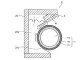
一方、現像ユニット3は、図3に示すように、トナーTを担持する現像ローラ11と、現像ブレード(規制部材)11と、これらを固定する現像枠体20と、を有している。現像枠体20は、現像ローラ11が配置された現像室20aと、現像室20aから外界へつながる現像開口(開口部)20bと、を備えている。現像ブレード30の一端が現像開口20bに固定され、現像ブレード30の他端が現像ローラ11に当接させられ、現像ローラ11上のトナーコート量規制と、トナーTへの摩擦電荷(トリボ)の付与と、が可能な構成とされている。現像ローラ11は、現像開口20bに配置され、感光体ドラム1に当接可能とされている。なお、現像ローラ11は、例えば基体11aに導電弾性層11b、表面層11cが順次積層され構成を有するローラであり、同図中の矢印の方向へ回転駆動するように配置されている。
On the other hand, as shown in FIG. 3, the developing
〔現像ローラ〕
本発明に係る現像ローラは、例えば、図9に示すように、円柱状または中空円筒状の導電性の基体11aの外周面に導電性弾性層11bが形成され、導電性弾性層の外周面に表面層11cが積層された構成とされる。現像ローラの構成はこれに限定されず、公知の現像ローラを使用することができる。
[Development roller]
In the developing roller according to the present invention, for example, as shown in FIG. 9, a conductive
〈基体〉
現像ローラに用いられる基体は、導電性を有し、その上に設けられる導電性弾性層を支持する機能を有する。基体の材質としては、例えば、鉄、銅、アルミニウム、ニッケルの如き金属;これらの金属を含むステンレス鋼、ジュラルミン、真鍮及び青銅の如き合金を挙げることができる。基体の表面には、耐傷性付与を目的として、導電性を損なわない範囲で、メッキ処理を施すことができる。さらに、基体としては、樹脂製の基材の表面を金属で被覆して表面導電性としたものや、導電性樹脂組成物から製造されたものも使用可能である。
<Hpokeimenon>
The substrate used for the developing roller has conductivity and has a function of supporting a conductive elastic layer provided on the substrate. Examples of the material of the substrate include metals such as iron, copper, aluminum and nickel; and alloys such as stainless steel containing these metals, duralumin, brass and bronze. The surface of the substrate can be plated for the purpose of imparting scratch resistance as long as the conductivity is not impaired. Further, as the substrate, a resin-made substrate whose surface is coated with a metal to make the surface conductive, or a substrate manufactured from a conductive resin composition can also be used.
〈導電性弾性層〉
導電性弾性層は、使用される装置において要求される弾性を現像ローラに付与するために設けられる。具体的な構成としては、中実体、発泡体のいずれであってもよい。また、導電性弾性層は、単層であっても、複数の層からなっていてもよい。例えば、現像ローラは、感光ドラム、及びトナーと常に圧接しているので、これらの部材間において相互に与えるダメージを低減するため、低硬度、低圧縮永久歪の特性を持つ導電性弾性層が設けられる。
<Conductive elastic layer>
The conductive elastic layer is provided to impart the elasticity required in the apparatus used to the developing roller. As a specific configuration, it may be either a medium substance or a foam. Further, the conductive elastic layer may be a single layer or may be composed of a plurality of layers. For example, since the developing roller is always in pressure contact with the photosensitive drum and the toner, a conductive elastic layer having low hardness and low compression permanent strain characteristics is provided in order to reduce mutual damage between these members. Be done.
導電性弾性層の材質としては、例えば、天然ゴム、イソプレンゴム、スチレンゴム、ブチルゴム、ブタジエンゴム、フッ素ゴム、ウレタンゴム、シリコーンゴムを挙げることができる。これらは1種単独で又は2種以上を組み合わせて使用することができる。 Examples of the material of the conductive elastic layer include natural rubber, isoprene rubber, styrene rubber, butyl rubber, butadiene rubber, fluororubber, urethane rubber, and silicone rubber. These can be used alone or in combination of two or more.
導電性弾性層には、現像ローラに要求される機能に応じて導電剤、非導電性充填剤や、その他成型に必要な各種添加剤成分として、架橋剤、触媒、分散促進剤が含有されていてもよい。 The conductive elastic layer contains a cross-linking agent, a catalyst, and a dispersion accelerator as various additive components necessary for molding, such as a conductive agent, a non-conductive filler, and other components necessary for molding, depending on the functions required of the developing roller. You may.
導電性弾性層に配合される導電剤としては、各種導電性金属又は合金、導電性金属酸化物、これらで被覆された絶縁性物質の微粉末、カーボンブラック等の電子導電剤や、イオン導電剤を用いることができる。これら導電剤は粉末状や繊維状の形態で、1種単独でまたは2種類以上を組み合わせて使用することができる。これらのうち、電子導電剤であるカーボンブラックは導電性の制御が容易であり、また経済的であることから好ましい。このような導電剤を含有させて、導電性弾性層の体積抵抗率を1×10⁴〜1×10¹⁰Ω・cmに制御することができる。導電性弾性層の体積抵抗率がこの範囲内である現像ローラでは、感光ドラムに対するトナー現像量の制御が容易となる。導電性弾性層の体積抵抗率は、より好ましくは1×10⁴〜1×10⁹Ω・cmである。 Examples of the conductive agent to be blended in the conductive elastic layer include various conductive metals or alloys, conductive metal oxides, fine powders of insulating substances coated with these, electronic conductive agents such as carbon black, and ion conductive agents. Can be used. These conductive agents may be used alone or in combination of two or more in the form of powder or fibrous. Of these, carbon black, which is an electron conductive agent, is preferable because its conductivity can be easily controlled and it is economical. By containing such a conductive agent, the volume resistivity of the conductive elastic layer can be controlled to 1 × 10 4 to 1 × 10 10 Ω · cm. In a developing roller in which the volume resistivity of the conductive elastic layer is within this range, it becomes easy to control the amount of toner developed with respect to the photosensitive drum. The volume resistivity of the conductive elastic layer is more preferably 1 × 10 4 to 1 × 10 9 Ω · cm.
導電性弾性層に含有されていてもよい非導電性充填剤としては、例えば、以下のものを例示することができる。珪藻土、石英粉末、乾式シリカ、湿式シリカ、酸化チタン、酸化亜鉛、アルミノケイ酸、炭酸カルシウム、珪酸ジルコニウム、珪酸アルミニウム、タルク、アルミナ、酸化鉄。 Examples of the non-conductive filler that may be contained in the conductive elastic layer include the following. Diatomaceous earth, quartz powder, dry silica, wet silica, titanium oxide, zinc oxide, aluminosilicic acid, calcium carbonate, zirconium silicate, aluminum silicate, talc, alumina, iron oxide.
導電性弾性層は、現像ローラに要求される弾性を付与し、その硬度としては、例えば、アスカーC硬度が10度以上80度以下であることが好ましい。導電性弾性層のアスカーC硬度が10度以上であれば、現像ローラに対向配置される各部材による圧縮永久歪を抑制できる。また、導電性弾性層のアスカーC硬度が80度以下であれば、トナーへのストレスを抑制することができ、画像形成を繰り返すことによる画質の低下を抑制することができる。ここでアスカーC硬度は、アスカーゴム硬度計(高分子計器(株)製)により測定した測定値によって規定することができる。 The conductive elastic layer imparts the elasticity required for the developing roller, and the hardness thereof is preferably, for example, Asker C hardness of 10 degrees or more and 80 degrees or less. When the Asker C hardness of the conductive elastic layer is 10 degrees or more, compression set by each member arranged facing the developing roller can be suppressed. Further, when the Asker C hardness of the conductive elastic layer is 80 degrees or less, stress on the toner can be suppressed, and deterioration of image quality due to repeated image formation can be suppressed. Here, the Asker C hardness can be defined by a measured value measured by an Asker rubber hardness tester (manufactured by Polymer Meter Co., Ltd.).
導電性弾性層の厚さとしては、例えば0.1mm以上50mm以下であり、より好ましくは0.5mm以上10mm以下である。 The thickness of the conductive elastic layer is, for example, 0.1 mm or more and 50 mm or less, and more preferably 0.5 mm or more and 10 mm or less.
導電性弾性層の成形方法としては、例えば、押出成形、プレス成形、射出成形、液状射出成形、注型成形の各種成形法により、適切な温度および時間で加熱硬化させて基体上に成形する方法を挙げることができる。注型成形の場合は、基体を設置した円筒形金型内に未硬化の導電性弾性層用の材料を注入し、加熱硬化する方法によって、基体の周囲に導電性弾性層を精度よく成形することができる。 As a method for forming the conductive elastic layer, for example, a method of heat-curing at an appropriate temperature and time by various molding methods such as extrusion molding, press molding, injection molding, liquid injection molding, and casting molding to form the conductive elastic layer on a substrate. Can be mentioned. In the case of casting molding, the material for the uncured conductive elastic layer is injected into a cylindrical mold on which the substrate is installed, and the conductive elastic layer is accurately molded around the substrate by a method of heat curing. be able to.
〈表面層〉
現像ローラには、トナー搬送、帯電付与等の現像ローラとして必要とされる特性を満たすため、導電性弾性層の外周に表面層の如き層が設けられていてもよい。表面層は上記特性を満たすため、樹脂層であることが好ましく、表面層を構成する樹脂としては例えば、フッ素樹脂,ポリアミド樹脂,メラミン樹脂,シリコーン樹脂,ウレタン樹等及びこれらの混合物が挙げられる。
<Surface layer>
The developing roller may be provided with a layer such as a surface layer on the outer periphery of the conductive elastic layer in order to satisfy the characteristics required as a developing roller such as toner transfer and charging. In order to satisfy the above characteristics, the surface layer is preferably a resin layer, and examples of the resin constituting the surface layer include fluororesin, polyamide resin, melamine resin, silicone resin, urethane tree, and the like, and a mixture thereof.
表面層には樹脂に導電性や補強性を付与する目的でカーボンブラックを添加したものを用いることができる。カーボンブラックの配合量は樹脂成分に対して3質量%以上30質量%以下とすることが好ましい。表面層は、例えば、前記樹脂とカーボンブラックと溶剤を混合、分散した塗工液を導電性弾性層に塗工することによって得ることができる。塗工液に用いる溶剤としては、表面層として用いる樹脂が溶解するという条件内で適宜使用することができる。 As the surface layer, one to which carbon black is added can be used for the purpose of imparting conductivity and reinforcing property to the resin. The blending amount of carbon black is preferably 3% by mass or more and 30% by mass or less with respect to the resin component. The surface layer can be obtained, for example, by applying a coating liquid in which the resin, carbon black, and a solvent are mixed and dispersed on the conductive elastic layer. As the solvent used in the coating liquid, it can be appropriately used under the condition that the resin used as the surface layer is dissolved.
表面層の厚みは4μm以上50μm以下が好ましい。厚みが4μm以上であれば使用時の摩耗を抑制でき、50μm以下であれば現像ローラの表面硬度によるトナーへのストレスを抑制できる。 The thickness of the surface layer is preferably 4 μm or more and 50 μm or less. If the thickness is 4 μm or more, wear during use can be suppressed, and if it is 50 μm or less, stress on the toner due to the surface hardness of the developing roller can be suppressed.
表面層の表面粗さは特に限定されず、トナーの搬送力を確保して高品位な画像を得る目的で、適宜調整して用いることができる。表面粗さを制御する手段としては、表面層に所望の粒径の粒子を含有させることが有効である。表面層に含有させる粒子としては、粒径0.1μm以上30.0μm以下の金属粒子及び樹脂粒子を用いることができる。中でも、柔軟性に富み、比較的比重が小さくて塗料の安定性が得やすい樹脂粒子がより好ましい。表面層を複数層形成する場合には、複数層の全てに粒子を含有させても良く、複数層のうちの少なくとも一層に粒子を含有させても良い。 The surface roughness of the surface layer is not particularly limited, and can be appropriately adjusted and used for the purpose of securing the toner transporting power and obtaining a high-quality image. As a means for controlling the surface roughness, it is effective to include particles having a desired particle size in the surface layer. As the particles contained in the surface layer, metal particles and resin particles having a particle size of 0.1 μm or more and 30.0 μm or less can be used. Among them, resin particles having high flexibility, relatively small specific gravity, and easy to obtain stability of the coating material are more preferable. When forming a plurality of surface layers, particles may be contained in all of the plurality of layers, or particles may be contained in at least one of the plurality of layers.
本実施例では、現像ローラ11と感光体ドラム1は、対向部において各々の表面が同方向(本実施例では重力方向上方からから下方に向かう方向)に移動するようにそれぞれ回転させる。そして、所定の直流電圧を現像ローラ11に印加し、摩擦帯電よりマイナスに帯電したトナーで、感光体ドラム1に接触する現像部において、静電潜像を顕像化し、トナー像を形成している。なお、本実施例では、現像ローラ11は、感光体ドラム1に接触して配置されているが、現像ローラ11は、感光体ドラム1に対して所定間隔を開けて近接配置される構成であってもよい。
In this embodiment, the developing
<現像ブレードの構成>
図1を用いて、本実施例における現像ブレードの構成を詳細に説明する。現像ブレード30は、現像ローラ11に対してカウンター方向を向くようにして当接しており、トナーのコート量の規制及び電荷付与を行っている。本実施例では、現像ブレード30として、厚さ50〜120μmの板バネ状のSUS板の支持部32を用い、支持部32のバネ弾性を利用して、ブレード部31の表面を現像ローラ11に当接させている。現像ブレード11は、短手方向において、一端にブレード部31が形成され、他端が現像枠体20に固定された支持部材Sに接続され、支持された構成とされている。
<Structure of developing blade>
The configuration of the developing blade in this embodiment will be described in detail with reference to FIG. The developing
支持部とブレード部を構成する材料は単一の材料であっても、それぞれ異なる材料であってもよい。現像ブレードに用いられる支持部としては、ブレード部の支持が可能であれば、特に制限されるものではない。尚、本発明において、支持部及びブレード部は、両者が互いに別箇独立した部材として存在する形態に限定されず、両者が一体化されて現像ブレードの支持部及びブレード部として存在する形態も含まれる。 The materials constituting the support portion and the blade portion may be a single material or different materials. The support portion used for the developing blade is not particularly limited as long as the blade portion can be supported. In the present invention, the support portion and the blade portion are not limited to the form in which both exist as separate and independent members, but also include the form in which the two are integrated and exist as the support portion and the blade portion of the developing blade. Is done.
[ブレード部]
ブレード部の材質も特に限定されず、ゴム、熱可塑性エラストマーの如き弾性材料、各種樹脂が挙げられる。具体的には以下のものが挙げられる。ゴム弾性を有する熱硬化性ポリウレタンゴム、シリコーンゴム、液状ゴムの如きゴム;ポリエステル樹脂、ポリアミド樹脂、ポリエーテル樹脂等の如き熱可塑性樹脂;ポリエステルエラストマー、ポリウレタンエラストマー、ポリアミドエラストマーの如き熱可塑性エラストマー。
[Blade part]
The material of the blade portion is not particularly limited, and examples thereof include rubber, elastic materials such as thermoplastic elastomers, and various resins. Specific examples include the following. Rubbers with rubber elasticity Rubbers such as thermosetting polyurethane rubbers, silicone rubbers and liquid rubbers; thermoplastic resins such as polyester resins, polyamide resins and polyether resins; thermoplastic elastomers such as polyester elastomers, polyurethane elastomers and polyamide elastomers.
ブレード部を構成する材料が支持部を構成する材料と異なる場合、以下の材料がブレード部として使用可能である。シリコーン樹脂、シリコーンゴム、ウレタン樹脂、ウレタンゴム、フェノール樹脂、尿素樹脂、メラミン樹脂、アクリル樹脂、エポキシ樹脂の如き熱硬化性樹脂またはゴム;及び、アクリル樹脂、ポリエチレン樹脂、ポリアミド樹脂、ポリエステル樹脂、ポリエーテル樹脂如き熱可塑性樹脂。なかでも、熱可塑性樹脂は、熱を加えることで容易に所望の形状に変形できるため、熱可塑性樹脂でブレード部を成形することが好ましい。 When the material constituting the blade portion is different from the material constituting the support portion, the following materials can be used as the blade portion. Thermocurable resins or rubbers such as silicone resins, silicone rubbers, urethane resins, urethane rubbers, phenolic resins, urea resins, melamine resins, acrylic resins, epoxy resins; and acrylic resins, polyethylene resins, polyamide resins, polyester resins, poly Thermoplastic resin such as ether resin. Among them, since the thermoplastic resin can be easily deformed into a desired shape by applying heat, it is preferable to mold the blade portion with the thermoplastic resin.
支持部とブレード部の材料が異なる場合、ブレード部の厚さ(図5におけるZ方向の距離)は、特に制限されず、現像剤層厚規制部では、10μm以上、3mm以下が好ましい。現像剤層厚規制部のブレード部の厚さが10μm以上であれば、樹脂またはゴムとしての弾性を維持しつつ現像ローラとの摩擦による磨耗に対する耐久性を確保できる。また、現像剤層厚規制部のブレード部の厚さが3mm以下であれば、現像ローラとの安定した当接圧を得ることができる。 When the materials of the support portion and the blade portion are different, the thickness of the blade portion (distance in the Z direction in FIG. 5) is not particularly limited, and the developer layer thickness regulating portion preferably has a thickness of 10 μm or more and 3 mm or less. When the thickness of the blade portion of the developer layer thickness regulating portion is 10 μm or more, durability against abrasion due to friction with the developing roller can be ensured while maintaining elasticity as resin or rubber. Further, when the thickness of the blade portion of the developer layer thickness regulating portion is 3 mm or less, a stable contact pressure with the developing roller can be obtained.
支持部に対するブレード部の形成箇所は特に限定されず、ブレード部は、支持部の現像ローラに当接する側の片面に形成することができ、また、支持部の両面を被覆する形状に形成することができる。例えば図5に示すように、支持部の一端に現像剤規制部と突出し部が形成されたブレード部が配置され、支持部が突出し部の位置まで延在している構成を挙げることができる。 The location where the blade portion is formed with respect to the support portion is not particularly limited, and the blade portion can be formed on one side of the support portion on the side that comes into contact with the developing roller, and is formed in a shape that covers both sides of the support portion. Can be done. For example, as shown in FIG. 5, a configuration in which a developer regulating portion and a blade portion having a protruding portion formed therein are arranged at one end of the supporting portion, and the supporting portion extends to the position of the protruding portion can be mentioned.
ブレード部の形成は、金型成型、押出成形、塗布成形、シートの貼り合せ成形、射出成型、などによって行うことができる。具体的には、金型成型や押出成形による場合、必要に応じて接着剤を塗布した支持部を成形金型に設置し、成型金型に加熱溶融した樹脂材料を注入して、ブレード部を支持部に接合した形態で成型することができる。また、シートの貼り合せ成形による場合、押出し成形等でシート状に成形したブレード部を、接着剤を塗布した支持部に貼り合わせることができる。また射出成型による場合、金型キャビティ内に上記樹脂材料を注入し、冷却してブレード部を成型することができる。 The blade portion can be formed by mold molding, extrusion molding, coating molding, sheet laminating molding, injection molding, or the like. Specifically, in the case of mold molding or extrusion molding, if necessary, a support portion coated with an adhesive is installed in the molding mold, and a heat-melted resin material is injected into the molding mold to make the blade portion. It can be molded in the form of being joined to the support portion. Further, in the case of laminating molding of sheets, the blade portion formed into a sheet by extrusion molding or the like can be laminating to the supporting portion to which the adhesive is applied. Further, in the case of injection molding, the above resin material can be injected into the mold cavity and cooled to mold the blade portion.
ブレード部を形成するにあたり、必要に応じて支持部上に接着剤層を形成することができる。接着剤層の材質としては、例えば、ホットメルト系接着剤として、ポリウレタン系、ポリエステル系、エチレンビニルアルコール系(EVA系)、ポリアミド系の接着剤を挙げることができる。 In forming the blade portion, an adhesive layer can be formed on the support portion, if necessary. Examples of the material of the adhesive layer include polyurethane-based, polyester-based, ethylene-vinyl alcohol-based (EVA-based), and polyamide-based adhesives as hot-melt adhesives.
[支持部]
支持部の材質としては、特に限定されず、SUSの他、クロメート処理及び潤沢樹脂等の表面処理鋼板、ステンレス鋼、りん青銅、アルミニウムなどの金属や、アクリル樹脂、ポリエチレン樹脂、ポリエステル樹脂などの樹脂を挙げることができる。樹脂を使用する場合で導電性が必要とされる場合は、樹脂に導電材料を加えることが好ましい。
[Support]
The material of the support portion is not particularly limited, and in addition to SUS, surface-treated steel sheets such as chromate-treated and abundant resins, metals such as stainless steel, phosphorous bronze, and aluminum, and resins such as acrylic resin, polyethylene resin, and polyester resin. Can be mentioned. When a resin is used and conductivity is required, it is preferable to add a conductive material to the resin.
支持部の厚さ(図5におけるZ方向の距離)は特に制限されず、0.05mm以上、3mm以下が好ましい。特に、支持部の厚さが0.05mm以上0.15mm以下の薄板である場合は、支持部が適度のバネ性を有するため、現像ローラにブレード部を適正な当接圧で当接させることができ、現像ローラ上のトナーを適正な層厚に規制することができる。また、支持部の厚さが0.8mm以上の場合は、現像装置、プロセスカートリッジおよび電子写真画像形成装置への現像ブレードの取り付け及びその位置設定が容易で、かつ歪等なく設置できるため、現像ローラに対してブレード部を安定して適正な当接圧で当接することが可能になる。 The thickness of the support portion (distance in the Z direction in FIG. 5) is not particularly limited, and is preferably 0.05 mm or more and 3 mm or less. In particular, when the thickness of the support portion is 0.05 mm or more and 0.15 mm or less, the support portion has an appropriate spring property, so that the blade portion should be brought into contact with the developing roller with an appropriate contact pressure. It is possible to regulate the toner on the developing roller to an appropriate layer thickness. Further, when the thickness of the support portion is 0.8 mm or more, it is easy to attach the developing blade to the developing device, the process cartridge, and the electrophotographic image forming device and set the position thereof, and it can be installed without distortion. It is possible to stably contact the blade portion with the roller with an appropriate contact pressure.
支持部とブレード部を構成する材料が単一であって、材質が金属である場合は、支持部は、プレス等の曲げ加工、電気化学機械加工、放電機械加工、レーザービーム機械加工、等の方法によって成型することが可能である。 When the material constituting the support part and the blade part is a single material and the material is metal, the support part may be used for bending such as pressing, electrochemical machining, discharge machining, laser beam machining, etc. It can be molded by the method.
また支持部の材質が熱可塑性樹脂である場合は、例えば、押出成形、射出成型などによって支持部を成型することができる。具体的には、押出成形による場合、成型金型内に加熱溶融した上記熱可塑性樹脂を注入して支持部を成型することができる。また射出成型による場合、金型キャビティ内に上記熱可塑性樹脂を注入し、冷却して支持部を成型することができる。 When the material of the support portion is a thermoplastic resin, the support portion can be molded by, for example, extrusion molding or injection molding. Specifically, in the case of extrusion molding, the support portion can be molded by injecting the above-mentioned thermoplastic resin that has been heated and melted into a molding die. Further, in the case of injection molding, the thermoplastic resin can be injected into the mold cavity and cooled to mold the support portion.
[導電剤]
支持部やブレード部や接着剤層には、必要に応じて導電剤を付与することができる。導電剤としては、イオン導電剤やカーボンブラックのような電子導電剤が挙げられる。
[Conducting agent]
A conductive agent can be applied to the support portion, the blade portion, and the adhesive layer, if necessary. Examples of the conductive agent include an ionic conductive agent and an electronic conductive agent such as carbon black.
カーボンブラックとしては、具体的には、「ケッチェンブラック」(商品名、ライオン(株)製)、アセチレンブラックの如き導電性カーボンブラック;SAF、ISAF、HAF、FEF、GPF、SRF、FT、MTの如きゴム用カーボンブラックを挙げることができる。その他、酸化処理を施したカラーインク用カーボンブラック、熱分解カーボンブラックを用いることができる。カーボンブラックの使用量は、樹脂またはゴム100質量部に対し5質量部以上50質量部以下であることが好ましい。樹脂またはゴム中におけるカーボンブラックの含有量は熱重量分析装置(TGA)を用いて測定することができる。 Specific examples of carbon black include conductive carbon blacks such as "Ketchen Black" (trade name, manufactured by Lion Corporation) and acetylene black; SAF, ISAF, HAF, FEF, GPF, SRF, FT, MT. Carbon black for rubber such as. In addition, carbon black for color ink and thermally decomposed carbon black that have been subjected to oxidation treatment can be used. The amount of carbon black used is preferably 5 parts by mass or more and 50 parts by mass or less with respect to 100 parts by mass of resin or rubber. The content of carbon black in the resin or rubber can be measured using a thermogravimetric analyzer (TGA).
上記カーボンブラックの他、使用可能な電子導電剤としては、以下のものを挙げることができる。天然グラファイト、人造グラファイトの如きグラファイト;銅、ニッケル、鉄、アルミニウムの如き金属粉;酸化チタン、酸化亜鉛、酸化錫の如き金属酸化物粉;ポリアニリン、ポリピロール、ポリアセチレンの如き導電性高分子。これらは必要に応じて1種単独で又は2種以上を組み合わせて用いることができる。 In addition to the above carbon black, the following can be mentioned as usable electronic conductive agents. Graphites such as natural graphite and artificial graphite; metal powders such as copper, nickel, iron and aluminum; metal oxide powders such as titanium oxide, zinc oxide and tin oxide; conductive polymers such as polyaniline, polypyrrole and polyacetylene. These can be used alone or in combination of two or more, if necessary.
イオン導電剤としては、例えば以下のものが挙げられる。テトラエチルアンモニウム、テトラブチルアンモニウム、ラウリルトリメチルアンモニウム、ドデシルトリメチルアンモニウム、ステアリルトリメチルアンモニウム、オクタデシルトリメチルアンモニウム、ヘキサデシルトリメチルアンモニウム、ベンジルトリメチルアンモニウム、変性脂肪族ジメチルエチルアンモニウムの如きアンモニウムイオンを含む、過塩素酸塩、塩素酸塩、塩酸塩、臭素酸塩、ヨウ素酸塩、ホウフッ化水素酸塩、トリフルオロメチル硫酸塩、スルホン酸塩、ビス(トリフルオロメチルスルホン酸)イミド塩;リチウム、ナトリウム、カルシウム、マグネシウムの如きアルカリ金属又はアルカリ土類金属を含む、過塩素酸塩、塩素酸塩、塩酸塩、臭素酸塩、ヨウ素酸塩、ホウフッ化水素酸塩、トリフルオロメチル硫酸塩、スルホン酸塩、ビス(トリフルオロメチルスルホン酸)イミド塩など。中でも、アルカリ金属又はアンモニウムイオンのトリフルオロメチル硫酸塩、ビス(トリフルオロメチルスルホン酸)イミド塩が好ましい。これらの塩は、アニオンにフッ素を含有した構造を有しているため、導電性付与効果が大きいので好適である。これらは必要に応じて1種単独で又は2種以上を組み合わせて用いることができる。 Examples of the ionic conductive agent include the following. Perchlorates, including ammonium ions such as tetraethylammonium, tetrabutylammonium, lauryltrimethylammonium, dodecyltrimethylammonium, stearyltrimethylammonium, octadecyltrimethylammonium, hexadecyltrimethylammonium, benzyltrimethylammonium, modified aliphatic dimethylethylammonium. Chlorate, hydrochloride, bromate, ammonium salt, borohydrochloride, trifluoromethylsulfate, sulfonate, bis (trifluoromethylsulfonic acid) imide salt; of lithium, sodium, calcium, magnesium Perchlorates, chlorates, hydrochlorides, bromines, iodates, borohydrochlorides, trifluoromethylsulfates, sulfonates, bis (tri), including such alkali metals or alkaline earth metals. Fluoromethylsulfonic acid) imide salt and the like. Of these, alkali metal or ammonium ion trifluoromethyl sulfates and bis (trifluoromethylsulfonic acid) imide salts are preferable. Since these salts have a structure in which fluorine is contained in the anion, they are suitable because they have a large effect of imparting conductivity. These can be used alone or in combination of two or more, if necessary.
支持部やブレード部や接着剤層には、その他、上記樹脂もしくはゴム、及び導電剤の機能を阻害しない範囲で、荷電制御剤、潤滑剤、充填剤、酸化防止剤、老化防止剤を含有させることができる。 In addition, the support portion, the blade portion, and the adhesive layer contain a charge control agent, a lubricant, a filler, an antioxidant, and an anti-aging agent as long as the functions of the resin or rubber and the conductive agent are not impaired. be able to.
本実施例ではブレード部31は、現像ローラ11の回転方向の下流側から順に、現像ローラ11に向かって突出し接触する突出部31dと、一端が突出部31dにつながり他端が自由端となる、現像ローラ11と対向する対向面31c1と、を有している。この突出部31dにおいては、現像ローラ11と接触する当接部(ニップ部)Nが形成されている。
In this embodiment, the
当接部(ニップ部)Nでは、現像ローラ11が回転することにより、現像ローラ11との摺擦により摩擦帯電され、電荷が付与されると同時に、現像ローラ11上のトナーTの層厚が規制され、均一となるようにされている。本実施例では、ブレード部31を現像ローラ11に50gf/cmの力で当接させた時に、ブレード部31と現像ローラ11の間の当接幅(ニップ幅)Wが600〜800μmとなる構成とした。また、本実施例においては、現像ブレード30に不図示のブレード電圧電源から所定電圧を印加し、トナーコートの安定化を図っている。
At the contact portion (nip portion) N, the rotation of the developing
なお、ブレード部は、現像ローラとの当接部となる、現像剤層厚規制部の現像ローラの回転方向の長さW(図10における円弧の距離)が、1.0mm以上5.0mm以下であることが好ましい。図10に示すように、現像剤層厚規制部が、現像ローラの表面に沿うように曲面を形成していると、長い当接幅を確保することができる。 The blade portion has a length W (distance of the arc in FIG. 10) in the rotation direction of the developing roller layer thickness regulating portion, which is a contact portion with the developing roller, of 1.0 mm or more and 5.0 mm or less. Is preferable. As shown in FIG. 10, when the developer layer thickness regulating portion forms a curved surface along the surface of the developing roller, a long contact width can be secured.
一方、対向面31c1は、現像ローラ11が回転することにより、現像ローラ11と対向面31c1の間にトナーが供給され、対向面31c1の法線方向にトナーからの圧力F2が加わるように構成されている。
On the other hand, the facing surface 31c1 is configured such that toner is supplied between the developing
そこで本構成では、対向面31c1は、突出部31dにつながる一端から自由端となる他端へ向かうにつれて、現像ローラ11との距離が等しい、又は近づく構成、具体的には、変極点を有さない曲率半径Rの曲面を持った対向面31c1とした。対向面31c1が変極点を有さない曲面とすることにより、トナーからの圧力F2を、現像ブレード30を変形させる、支持部32の短手方向に延びる面と直交する方向への力から一部を支持部32の短手方向への力に分散させることができる。これにより、現像ブレード30がトナーから受ける力を分散させることができ、現像ローラ11から離れる方向に押し上げられ、変形することを抑制し、現像ブレード30と現像ローラ11間に適正な当接圧が加わり、所定の当接幅Wとすることができる。
Therefore, in this configuration, the facing surface 31c1 has a configuration in which the distance from the developing
さらに発明者の検討の結果、対向面31c1の曲率半径Rを以下の範囲にすることが好ましいことがわかった。現像ローラ11の半径をN(mm)としたとき、対向面31c1を構成する連続した曲面の曲率半径Rは、R=N±0.5N(mm)とすることが好ましいことがわかった。これにより、曲率半径Rを現像ローラ11と現像ブレード30の先端が当接しない下限値から、対向面31c1と現像ローラ11の間に供給されるトナー量を適当な量にしつつ、現像ブレード30の変形に寄与する力の発生を低減できる範囲とすることができる。
Further, as a result of the examination by the inventor, it was found that it is preferable to set the radius of curvature R of the facing surface 31c1 in the following range. It was found that when the radius of the developing
この結果、現像ブレード30と現像ローラ11の当接圧が低くなる問題や、現像ブレード30の現像ローラ11と接触する部分に生じるトナー固着の問題を抑制する。ひいては本実施例では、現像ブレード30によるトナーの規制不良、ひいては画像不良の発生を抑制することができる。
As a result, the problem that the contact pressure between the developing
また従来、トナーTは各トナー粒子の帯電量が不均一となることがあった。これは、トナーTは大きく分けて、3種類のトナー粒子を含むためと考えられる。1つ目は、現像ローラ11と接触して電荷の授受を行ったトナー粒子T1である。2つ目は、逆に現像ローラ11と接触せず、一切電荷を授受しないトナー粒子T2である。そして、3つ目は、現像ローラ11に接触しなかったものの、現像ローラ11と接触し、電荷を授受したトナー粒子T1と接触し、このトナー粒子T1より間接的に電荷を授受したトナー粒子T3である。このようにトナーTは、現像ローラ11から授受した電荷量が異なるトナー粒子T1、T2、T3を有する。このため、感光体ドラム1上の静電潜像を現像する際に、画像形成部のトナー濃度が薄くなったり、非画像形成部にトナーが付着するかぶりが発生したりして、画像不良を生じさせることがあった。
Further, conventionally, in the toner T, the charge amount of each toner particle may be non-uniform. It is considered that this is because the toner T is roughly divided into three types of toner particles. The first is the toner particles T1 that have been in contact with the developing
そこで本実施例では、対向面31c1を構成する連続した曲面の両端を結ぶ直線の距離、つまりブレード部31側の自由端(先端)から突出した突出部31dを構成する段差までの対向面31c1の長さをL1とし、0.85≦L1(mm)≦2.00とした。また、支持部32の短手方向に延びる面と直交する方向における、対向面31c1と突出部31dの接続部からの突出部31c1の最大高さ、つまり突出部31c1の凸の大きさをHとし、0.1≦H(mm)≦0.3とした。この結果、現像ローラ11と対向面31c1との間でより良くトナー粒子T1、T2、T3を互いに接触させ、トナーTの各トナー粒子が有する帯電量(電荷量)を平均化することができ、かぶり等の画像不良の発生を抑制することができる。
Therefore, in this embodiment, the distance of a straight line connecting both ends of the continuous curved surface forming the facing surface 31c1, that is, the facing surface 31c1 from the free end (tip) on the
加えて本実施例では、現像ブレード30は、対向面31c1が構成される範囲において、突出部31dにつながる一端から自由端となる他端へ向かうにつれて、接部(ニップ部)Nにおける現像ローラ11の法線方向における厚さが厚くなる構成とした。これにより、ブレード部31と現像ローラ11の間の当接幅Wを十分に確保し得る構成とすることができる他、当接部Nの位置を当接状況に依らず一定とすることができ、現像ローラ11に対してブレード部31を安定して当接させることができる。
In addition, in the present embodiment, the developing
また、図5に示す現像ブレードは、図1とは形状が異なるものの、いずれも現像剤層厚規制部と突出し部とを有し、該突出し部は、現像ローラに対向する側の表面(対向面)が凹状に曲っている。そして、ブレード部が現像剤層厚規制部と突出し部とを有し、ブレード部31の先端方向には突出し部31cが設けられている。
Further, although the developing blade shown in FIG. 5 has a different shape from that of FIG. 1, each has a developer layer thickness regulating portion and a protruding portion, and the protruding portion is a surface (opposing) on the side facing the developing roller. The surface) is curved in a concave shape. The blade portion has a developer layer thickness regulating portion and a protruding portion, and a protruding
本構成に係る現像装置によれば、現像ローラにより搬送されるトナーが、現像ローラの表面と現像ブレードの突出し部(対向面31c1)との間の間隙が形成する「トナー剥ぎ取り領域」で、白ベタ画像の現像後の帯電量の高くなりすぎたトナーが現像ローラの表面から剥ぎ取られる。更に、現像ローラから剥ぎ取られたトナーと現像室20aから供給されるトナーが共に循環し、トナーの帯電量が均一となりゴースト画像を抑制することができる。
According to the developing apparatus according to this configuration, the toner conveyed by the developing roller is a "toner stripping region" in which a gap is formed between the surface of the developing roller and the protruding portion (opposing surface 31c1) of the developing blade. After developing a solid white image, the toner with an excessively high charge is stripped from the surface of the developing roller. Further, the toner stripped from the developing roller and the toner supplied from the developing
トナーの電荷量の差に起因する画像不良としては、ゴースト画像(先の画像の跡が後続の画像上に現れる現象)が知られている。画像濃度が0%の白ベタ画像を現像した領域と画像濃度100%の黒ベタ画像を現像した領域では、次に現像ブレードに規制されたトナーの電荷量の差が大きくなり易い。画像濃度の低い領域、特に白ベタ画像の領域では現像ローラ上のトナーが殆ど現像されないため、トナーは現像ブレードと現像剤供給ローラとの間で繰り返し摺擦されて、トナーの電荷量が高くなる傾向にある。また、画像濃度の高い領域、特に黒ベタ画像の領域では現像ローラ上のトナーがほぼ現像されるため、白ベタ画像の領域のトナーとの電荷量の差が大きくなってゴースト画像が発生する。 A ghost image (a phenomenon in which traces of a previous image appear on a subsequent image) is known as an image defect caused by a difference in the amount of charge of toner. In the region where a solid white image having an image density of 0% is developed and the region where a solid black image having an image density of 100% is developed, the difference in the amount of charge of the toner regulated by the developing blade tends to be large next. Since the toner on the developing roller is hardly developed in the region where the image density is low, particularly in the region where the white solid image is formed, the toner is repeatedly rubbed between the developing blade and the developer supply roller, and the amount of charge of the toner becomes high. There is a tendency. Further, since the toner on the developing roller is substantially developed in the region where the image density is high, particularly in the region of the black solid image, the difference in the amount of charge with the toner in the region of the white solid image becomes large, and a ghost image is generated.
そこで、現像剤層厚規制部と現像ローラの当接部より上流側において現像ローラの表面と非接触の間隙を形成し、この間隙の幅をGとし、この間隙の最大幅及び最小幅をそれぞれGmax及びGminとしたときに、
(1) 0.05mm≦G≦0.5mm
(2) Gmax/Gmin≦3.0
を満たし、かつ、数式(1)及び(2)を満たす該間隙の、現像ローラの表面の回転方向の連続した長さをL2としたときに、
(3) L2≧0.8mm
を満たすようにすることで、トナー剥ぎ取り領域は、現像ローラ上のトナーの剥ぎ取りとトナーを循環する効果が得られる。トナー剥ぎ取り領域では、トナーの搬送方向(現像ローラの回転方向)において、トナーを強く詰めた状態の狭く長い間隙を確保できるため、トナーの循環と共に、現像ローラの表面とトナーとの間の摺擦が起こる。この結果、現像ローラ上のトナーの荷電状態を均一にして、現像ローラ上のトナーの荷電状態の差に起因するゴースト画像の発生を抑制することができる。
Therefore, a gap that is not in contact with the surface of the developing roller is formed on the upstream side of the contact portion between the developer layer thickness regulating portion and the developing roller, the width of this gap is set to G, and the maximum width and the minimum width of this gap are defined as G. When Gmax and Gmin are used,
(1) 0.05 mm ≤ G ≤ 0.5 mm
(2) Gmax / Gmin ≤ 3.0
When the continuous length of the gap satisfying the above conditions (1) and (2) in the rotation direction of the surface of the developing roller is L2,
(3) L2 ≥ 0.8 mm
By satisfying the above conditions, the toner stripping area has the effect of stripping the toner on the developing roller and circulating the toner. In the toner stripping region, a narrow and long gap in a state where the toner is strongly packed can be secured in the toner transport direction (rotation direction of the developing roller), so that the toner is circulated and the surface of the developing roller and the toner are slid. Rubbing occurs. As a result, the charge state of the toner on the developing roller can be made uniform, and the generation of a ghost image due to the difference in the charge state of the toner on the developing roller can be suppressed.
本発明の現像装置において、突出し部の間隙の幅Gは、0.05mm以上0.5mm以下である。間隙の幅Gが0.05mmより小さい場合は、トナーを強く詰めた状態が強固になりすぎるため、トナーの循環が不足し、現像ローラから剥ぎ取られたトナーと現像室20aから供給されるトナーの帯電量が均一になり難い。また、間隙の幅Gが0.5mmより大きい場合は、突出し部の間隙領域にトナーが詰まった状態にならずトナー同士の摺擦が不足するため、白ベタ画像の現像後の帯電量の高くなりすぎたトナーを現像ローラの表面から剥ぎ取る効果が得られない。更に間隙の幅Gが、0.05mm以上0.3mm以下の範囲であると、現像ローラの表面のトナーの剥ぎ取りと、突出し部の間隙領域でのトナーの循環が好適に行われる。
In the developing apparatus of the present invention, the width G of the gap between the protruding portions is 0.05 mm or more and 0.5 mm or less. When the gap width G is smaller than 0.05 mm, the toner packed tightly becomes too strong, so that the toner circulation is insufficient, and the toner stripped from the developing roller and the toner supplied from the developing
本発明の現像装置において、間隙の最大幅と最小幅との割合「Gmax/Gmin」は、3.0以下である。この割合Gmax/Gminの値が3.0を超えると、突出し部の間隙領域にトナーが詰まった状態が不均一になる。突出し部の上流側の間隙が最小幅Gmin、下流側の間隙が最大幅Gmaxであり、Gmax/Gminの値が3.0を超える場合、突出し部の間隙領域でトナーは移動し易くなり、間隙領域にトナーが均一に詰まった状態にならない。そのため、トナー同士の摺擦が不足し、白ベタ画像の現像後の帯電量の高くなりすぎた現像ローラの表面のトナーを剥ぎ取る効果が得られない。また、突出し部の上流側の間隙が最大幅Gmax、下流側の間隙が最小幅Gminであり、Gmax/Gminの値が3.0を超える場合、間隙領域の上流部で取りこまれた多量のトナーにより、間隙領域の下流部にトナーが詰まり過ぎ、現像剤層厚規制部が持ち上げられてトナーの規制不良が発生する場合がある。 In the developing apparatus of the present invention, the ratio "Gmax / Gmin" between the maximum width and the minimum width of the gap is 3.0 or less. When the value of this ratio Gmax / Gmin exceeds 3.0, the state in which the toner is clogged in the gap region of the protruding portion becomes non-uniform. When the gap on the upstream side of the protruding portion has the minimum width Gmin and the gap on the downstream side has the maximum width Gmax, and the value of Gmax / Gmin exceeds 3.0, the toner easily moves in the gap region of the protruding portion, and the gap The area is not evenly filled with toner. Therefore, the rubbing between the toners is insufficient, and the effect of stripping the toner on the surface of the developing roller whose charge amount after development of the white solid image is too high cannot be obtained. Further, when the gap on the upstream side of the protruding portion has the maximum width Gmax and the gap on the downstream side has the minimum width Gmin and the value of Gmax / Gmin exceeds 3.0, a large amount of material taken in in the upstream portion of the gap region The toner may cause the toner to be excessively clogged in the downstream portion of the gap region, and the developer layer thickness regulating portion may be lifted to cause poor regulation of the toner.
前記数式(1)及び(2)を満たす間隙の、現像ローラの表面の現像ローラの回転方向の連続した長さをL2としたときに、L2は0.8mm以上である。この長さL2が0.8mm未満である場合、トナー剥ぎ取り領域においてトナー同士が摺擦する時間が不足するため、白ベタ画像の現像後の帯電量の高くなりすぎたトナーを現像ローラの表面から剥ぎ取る効果が得られない。また、この長さL2は3.0mm以下であることが好ましい。3.0mm以下である場合、トナー剥ぎ取り領域に強く詰められたトナーが突出し部の表面を押し上げるおそれがなく、現像剤層厚規制部でのトナー層の厚みの規制が良好である。 When the continuous length of the gap satisfying the mathematical formulas (1) and (2) in the rotation direction of the developing roller on the surface of the developing roller is L2, L2 is 0.8 mm or more. When this length L2 is less than 0.8 mm, the time for the toners to rub against each other in the toner stripping region is insufficient, so that the toner having an excessively high charge amount after the development of the white solid image is applied to the surface of the developing roller. The effect of peeling from is not obtained. Further, the length L2 is preferably 3.0 mm or less. When it is 3.0 mm or less, there is no possibility that the toner strongly packed in the toner stripping region pushes up the surface of the protruding portion, and the toner layer thickness regulation by the developer layer thickness regulating portion is good.
前記長さL2は、例えば図10に示される円周方向の距離であって、突出し部31cの表面の各2点と現像ローラの断面円の中心を結ぶ2つの直線D及びDと、現像ローラの表面との各交点の現像ローラ上での距離である。
The length L2 is, for example, a distance in the circumferential direction shown in FIG. 10, and includes two straight lines D and D connecting each two points on the surface of the protruding
本発明の現像装置において、現像ローラの表面側に対向する現像ブレードの突出し部の表面は、凹状に曲っている。突出し部の表面が凹状に曲っていることで、間隙の幅Gを0.05mm以上0.5mm以下の範囲内として、間隙領域の長さL2を長くすることができる。更に、この突出し部の表面形状は、凹状に湾曲していることが好ましい。突出し部の表面形状が湾曲していることで、現像ローラの回転方向において狭い間隙を長く確保できるため、トナー同士が摺擦されやすく、現像ローラ表面上の現像剤剥ぎ取りが効果的に行われる。 In the developing apparatus of the present invention, the surface of the protruding portion of the developing blade facing the surface side of the developing roller is curved in a concave shape. Since the surface of the protruding portion is curved in a concave shape, the width G of the gap can be set within the range of 0.05 mm or more and 0.5 mm or less, and the length L2 of the gap region can be lengthened. Further, the surface shape of the protruding portion is preferably curved in a concave shape. Since the surface shape of the protruding portion is curved, a long narrow gap can be secured in the rotation direction of the developing roller, so that the toners are easily rubbed against each other and the developer on the surface of the developing roller is effectively peeled off. ..
更に、現像剤層厚規制部の長さ(円弧の長さ)Wが、1.0mm以上5.0mm以下であることが好ましい。現像ブレードと現像ローラによる摺擦距離を長くすることで、トナーの電荷量を均一な高い値にすることができる。 Further, it is preferable that the length (length of the arc) W of the developer layer thickness regulating portion is 1.0 mm or more and 5.0 mm or less. By lengthening the rubbing distance between the developing blade and the developing roller, the amount of charge of the toner can be made a uniform high value.
<変形例>
なお、実施例では、図1に示すようにブレード部31は、現像ローラ11と所定空間を介して対向する曲率半径Rの曲面を持った対向面31c1を備えた構成とした。しかし、これに限らず、本発明の変形例として図4に示すように、ブレード部31は、現像ローラ11と所定空間を介して対向する、支持部32が延びる面に対して傾斜した斜面を持った対向面31c1を備えた構成としてもよい。なお、対向面31c1の形状以外の点は、実施例と同様の構成としているため、同様の構成については同じ符号を付し、説明を省略する。
<Modification example>
In the embodiment, as shown in FIG. 1, the
現像ブレード30は、支持部32の先端をブレード部31が覆うように形成される。またブレード部31は、実施例同様、支持部32の短手方向に延びる面と直交する方向における、対向面31c2と突出部31dの接続部からの突出部31c1の最大高さ、つまり突出部31c1の凸の大きさをH(mm)とする。
The developing
本変形例では図4(B)に示したとおり、対向面31c2が、当接部(ニップ部)Nにおける現像ローラ11の法線方向に対し、角度θ(°)だけ傾斜した平面、つまり斜面としている。つまり、対向面31c2の角度θ、対向面31c2の長さL1を所定の長さとし、実施例同様、突出部31dにつながる一端から自由端となる他端へ向かうにつれて、現像ローラ11との距離が近づく構成とした。
In this modification, as shown in FIG. 4 (B), the facing surface 31c2 is a plane in which the facing surface 31c2 is inclined by an angle θ (°) with respect to the normal direction of the developing
現像ローラ11が回転することにより、現像ローラ11と対向面31c2の間にトナーが供給され、対向面31c2の法線方向にトナーからの圧力F3が発生する。しかし本構成により、圧力F3をトナーからの圧力が現像ブレード30を変形させる、支持部32の短手方向に延びる面と直交する方向への力から一部を支持部32の短手方向への力とすることができる。この結果、現像ブレード30がトナーから受ける力を分散させることができ、現像ローラ11から離れる方向に押し上げられ、変形することを抑制し、現像ブレード30と現像ローラ11との間に適正な当接圧が加わり、所定の当接幅Wとすることができる。なお、発明者の検討の結果、当接部(ニップ部)Nにおける現像ローラ11の法線方向に対し、現像ローラ11の回転方向の上流側へ傾斜した角度θは、77°以下とすることがより好ましいことが分かった。角度θをこの範囲にすることにより、対向面31c2と現像ローラ11の間に供給されるトナー量を適当な量にしつつ、現像ブレード30の変形に寄与する力の発生を低減できる。
By rotating the developing
また本実施例では、現像ブレード30は、対向面31c2が構成される範囲において、突出部31dにつながる一端から自由端となる他端へ向かうにつれて、接部(ニップ部)Nにおける現像ローラ11の法線方向における厚さが厚くなる構成とした。これにより、ブレード部31と現像ローラ11の間の当接幅Wを十分に確保し得る構成とすることができる他、当接部Nの位置を当接状況に依らず一定とすることができ、現像ローラ11に対してブレード部31を安定して当接させることができる。
Further, in this embodiment, the developing
以上の構成により、現像ブレード30と現像ローラ11の当接圧が低くなる問題や、現像ブレード30の現像ローラ11と接触する部分に生じるトナー固着の問題を抑制する。ひいては本実施例では、現像ブレード30によるトナーの規制不良、ひいては画像不良の発生を抑制できる。
With the above configuration, the problem that the contact pressure between the developing
なお、本実施例においても、ブレード部31側の自由端(先端)から突出した突出部31dを構成する段差までの対向面31c2の長さL1を0.85≦L1(mm)≦2.00とした。また、支持部32の短手方向に延びる面と直交する方向における、対向面31c2と突出部31dの接続部からの突出部31c1の最大高さ、つまり突出部31c1の凸の大きさHを0.1≦H(mm)≦0.3とした。このようにして、現像ローラ11と対向面31c2との間でより良くトナー粒子T1、T2、T3を互いに接触させ、トナーTの各トナー粒子が有する帯電量(電荷量)を平均化し、かぶり等の画像不良の発生を抑制した。
Also in this embodiment, the length L1 of the facing surface 31c2 from the free end (tip) on the
(他の実施例)
現像ブレードの突出し部は、現像ローラに対向する側の表面が凹状に曲った形状を有している。凹状に曲った表面を有することで、現像ローラの表面に対して数式(1)及び(2)を満たす小幅の間隙を、現像ローラの回転方向の長い距離に亘って、確保することが可能になる。突出し部の形状としては、直線が折れ曲った形状、湾曲した形状などをとりうるが、湾曲した形状が好ましい。湾曲した形状である場合は角が存在しないため、突出し部の表面側のトナーを円滑に循環させせることができる。更に、突出し部の表面の湾曲形状は、現像ローラの断面円の同心円上にある円弧形状であることが好ましい。その場合、現像ローラの表面に対して小幅の間隙を、一定の状態で、現像ローラの回転方向の長い距離に亘って、確保することが可能になる。突出し部の形状としては、例えば、図5〜図10等に示す形状が挙げられる。
(Other Examples)
The protruding portion of the developing blade has a concavely curved surface on the side facing the developing roller. By having a concavely curved surface, it is possible to secure a narrow gap that satisfies the formulas (1) and (2) with respect to the surface of the developing roller over a long distance in the rotation direction of the developing roller. Become. The shape of the protruding portion may be a bent straight line, a curved shape, or the like, but a curved shape is preferable. In the case of a curved shape, since there are no corners, the toner on the surface side of the protruding portion can be smoothly circulated. Further, the curved shape of the surface of the protruding portion is preferably an arc shape on the concentric circles of the cross section of the developing roller. In that case, it is possible to secure a small gap with respect to the surface of the developing roller over a long distance in the rotation direction of the developing roller in a constant state. Examples of the shape of the protruding portion include the shapes shown in FIGS. 5 to 10 and the like.
図5に示すように、現像剤層厚規制部31aと突出し部31cとの境界の位置に、段差31bを設けることができる。現像ローラの表面と突出し部31cとの間隙において強く詰められたトナーによって突出し部の表面が押し上げられる場合があるが、段差31bを有することでトナー層の厚みを規制するエッジ部分を確保できるため、トナー層の厚みの規制不良の発生を抑制することができる。
As shown in FIG. 5, a
現像剤層厚規制部では現像ローラの表面との間で、トナー層の厚みの規制と摺擦によるトナーへの電荷付与が行われる。現像剤層厚規制部の形状は、平面、湾曲形状、凸形状、凹形状のいずれであってもよいが、図8に示すように、湾曲形状であることが特に好ましい。湾曲形状とすることで、現像剤層厚規制部と現像ローラによる摺擦距離が長くなり、トナーの電荷量を均一な高い値にすることができる。更に、湾曲形状が、現像ローラの表面に沿った形状が好ましい。 In the developer layer thickness regulating section, the thickness of the toner layer is regulated between the surface of the developing roller and the toner is charged by rubbing. The shape of the developer layer thickness regulating portion may be a flat shape, a curved shape, a convex shape, or a concave shape, but as shown in FIG. 8, a curved shape is particularly preferable. By forming the curved shape, the rubbing distance between the developer layer thickness regulating portion and the developing roller becomes long, and the amount of electric charge of the toner can be made a uniform high value. Further, the curved shape is preferably a shape along the surface of the developing roller.
支持部とブレード部を構成する材料が異なる場合は、支持部が突出し部の位置まで延在していると好ましい。支持部がその位置まで延在することにより突出し部の剛性が高くなるため、現像ローラの表面と突出し部の表面との間隙にトナーが強く詰まった状態でも、所望の間隙を維持することが可能になる。 When the materials constituting the support portion and the blade portion are different, it is preferable that the support portion extends to the position of the protruding portion. Since the support portion extends to that position, the rigidity of the protruding portion is increased, so that the desired gap can be maintained even when the gap between the surface of the developing roller and the surface of the protruding portion is strongly clogged with toner. become.
以下、製造例及び実施例により、本発明を具体的に説明する。尚、現像ブレードの突出し部の「先端」とは、図5のX方向の端部を意味し、現像ブレードの突出し部の「根元」とは、現像剤層厚規制部と突出し部との境界の位置を意味する。 Hereinafter, the present invention will be specifically described with reference to Production Examples and Examples. The "tip" of the protruding portion of the developing blade means the end portion in the X direction of FIG. 5, and the "root" of the protruding portion of the developing blade is the boundary between the developer layer thickness regulating portion and the protruding portion. Means the position of.
〔実施例2〕
1.現像ブレードの製造
ブレード部の材料としてポリエステル熱可塑性樹脂(TPEE)(東レ・デュポン株式会社製;商品名ハイトレル4047N)を用いた。支持部には、SUS‐304‐1/2H材の短手方向15.2mm、厚さ0.08mmの長尺シートを使用した。
[Example 2]
1. 1. Manufacture of developing blade Polyester thermoplastic resin (TPEE) (manufactured by Toray DuPont Co., Ltd .; trade name Hytrel 4047N) was used as the material for the blade portion. For the support portion, a long sheet of SUS-304-1 / 2H material having a short side direction of 15.2 mm and a thickness of 0.08 mm was used.
図12は、現像ブレードの製造装置である。まず、ブレード部用の材料を押出成形機内113にて200℃で溶融し、押出し用金型112の成型キャビティに注入した。また同時に、支持部の一端面を押出し用金型に成形キャビティに走行させながら、ブレード部を支持部の短手方向の一端面に被覆した。金型112の温度は250℃に設定した。
FIG. 12 is a developing blade manufacturing apparatus. First, the material for the blade portion was melted at 200 ° C. in 113 in the extrusion molding machine and injected into the molding cavity of the extrusion die 112. At the same time, the blade portion was covered on one end surface of the support portion in the lateral direction while the one end surface of the support portion was run through the molding cavity in the extrusion die. The temperature of the
押出し用金型112から吐出したブレード部を冷却機114により固化し、支持部の当接支持面、先端面、及び当接支持面の反対面がブレード部にて被覆された部材を得た。この部材を、切断機116により長手方向の長さ226mmで切断し、次いで、現像ローラに対向する側の表面を加工して、突出し部の表面の曲率半径Rを6.20mm、突出し部の長さL0を1.0mmとする図8に示す現像ブレードNo.1を得た。
The blade portion discharged from the extrusion die 112 was solidified by the cooler 114 to obtain a member in which the contact support surface, the tip surface, and the opposite surface of the contact support surface of the support portion were covered with the blade portion. This member is cut by a cutting
2.現像ローラの製造
基体として、外径6mm、長さ270mmのSUS304製の軸芯体にプライマー(商品名:DY35−051;東レダウコーニング社製)を塗布、焼付けしたものを用意した。この基体を金型内に配置し、下記表1に示す材料を混合した付加型シリコーンゴム組成物を、金型内に形成されたキャビティに注入した。
2. As a substrate for manufacturing a developing roller, a SUS304 shaft core having an outer diameter of 6 mm and a length of 270 mm was coated with a primer (trade name: DY35-051; manufactured by Toray Dow Corning) and baked. This substrate was placed in a mold, and an addition type silicone rubber composition mixed with the materials shown in Table 1 below was injected into a cavity formed in the mold.

続いて、金型を加熱してシリコーンゴム組成物を温度150℃で15分間加熱して硬化させ、脱型した後、さらに温度180℃で1時間加熱して硬化反応を完結させ、基体の外周に厚さ3mmの導電性弾性層を有する導電性弾性ローラを製造した。次に、下記表2に示す材料を秤量し、メチルエチルケトン100質量部を加えたのち、ビーズミルを用いて分散させ表面層塗工液とした。 Subsequently, the mold is heated to heat the silicone rubber composition at a temperature of 150 ° C. for 15 minutes to cure it, and after the mold is removed, it is further heated to a temperature of 180 ° C. for 1 hour to complete the curing reaction, and the outer periphery of the substrate is completed. A conductive elastic roller having a conductive elastic layer having a thickness of 3 mm was produced. Next, the materials shown in Table 2 below were weighed, 100 parts by mass of methyl ethyl ketone was added, and then dispersed using a bead mill to prepare a surface layer coating liquid.
続いて、上記導電性弾性ローラを、その長手方向を鉛直方向にして、基体の上端部を把持して、上記表面層塗工液中に浸漬してディッピング法で、膜厚10.0μmとなるように塗工した。浸漬時間は9秒間とし、塗工液からの塗工物の引き上げ速度は、初期速度30mm/s、最終速度20mm/s、及び、これらの間は、時間に対して直線的に速度を変化させた。得られた塗工物を、温度80℃のオーブン中で15分間乾燥後、温度140℃のオーブン中で2時間加熱して、硬化反応させて、表面層を設け、曲率半径DRが6.0mmの現像ローラNo.1を製造した。 Subsequently, the conductive elastic roller is immersed in the surface layer coating liquid by gripping the upper end portion of the substrate with its longitudinal direction in the vertical direction, and the film thickness is 10.0 μm by the dipping method. I painted it like this. The immersion time is 9 seconds, and the speed of pulling up the coating material from the coating liquid is an initial speed of 30 mm / s, a final speed of 20 mm / s, and during these speeds, the speed is changed linearly with time. rice field. The obtained coated product is dried in an oven at a temperature of 80 ° C. for 15 minutes, then heated in an oven at a temperature of 140 ° C. for 2 hours to cause a curing reaction to provide a surface layer, and the radius of curvature DR is 6.0 mm. Development roller No. 1 was manufactured.
3.現像装置の作製
上記現像ブレードNo.1と上記現像ローラNo.1を図5に示す現像装置に取り付けて、間隙の最大幅Gmax、間隙の最小幅Gminが共に0.2mm、割合Gmax/Gminが1.0、数式(1)及び(2)を満たす該間隙の、現像ローラの表面の回転方向の連続した長さL2(以下、「剥ぎ取り領域の長さL2」と称する。)が1.0mmとなるように設定した。
3. 3. Preparation of developing equipment The above developing blade No. 1 and the above-mentioned developing roller No. 1. 1 is attached to the developing apparatus shown in FIG. 5, the maximum width Gmax of the gap, the minimum width Gmin of the gap are both 0.2 mm, the ratio Gmax / Gmin is 1.0, and the gap satisfying the equations (1) and (2). The continuous length L2 of the surface of the developing roller in the rotation direction (hereinafter, referred to as “the length L2 of the stripping region”) was set to be 1.0 mm.
4.現像ブレードと現像ローラの間隙の形状測定
図10は、現像ブレードと現像ローラとの当接部を現像ブレードの長手方向に垂直な断面方向から見た図である。デジタルマイクロスコープ(キーエンス社製;VHX−5000)を用いてこの画面を500倍に拡大して観察した。間隙の幅Gが0.05mm以上0.5mm以下、且つ、割合Gmax/Gminが3.0以下となる間隙の長さL2を、現像ローラの表面上で測定した。測定は、現像ローラの表面上に沿って0.1mmピッチで行った。
4. Measuring the shape of the gap between the developing blade and the developing roller FIG. 10 is a view of the contact portion between the developing blade and the developing roller viewed from a cross-sectional direction perpendicular to the longitudinal direction of the developing blade. This screen was magnified 500 times and observed using a digital microscope (manufactured by KEYENCE; VHX-5000). The length L2 of the gap having a gap width G of 0.05 mm or more and 0.5 mm or less and a ratio Gmax / Gmin of 3.0 or less was measured on the surface of the developing roller. The measurement was performed at a pitch of 0.1 mm along the surface of the developing roller.
5.電子写真画像形成装置によるゴースト評価
電子写真画像形成装置(商品名:CLJ CP4525、ヒューレット・パッカード社製)用のプロセスカートリッジの現像装置に、現像ローラNo.1及び現像ブレードNo.1を組み込み、温度15℃、相対湿度10%の低温低湿環境下に24時間放置した。次に、評価用画像の印刷を行い、現像ゴーストの評価を行った。
5. Ghost evaluation by electrophotographic image forming apparatus In the developing apparatus of the process cartridge for the electrophotographic image forming apparatus (trade name: CLJ CP4525, manufactured by Hewlett-Packard Co., Ltd.), the developing roller No. 1 and the developing blade No. 1 was incorporated and left for 24 hours in a low temperature and low humidity environment with a temperature of 15 ° C. and a relative humidity of 10%. Next, the evaluation image was printed and the development ghost was evaluated.
現像ゴーストの判定は、紙先端に5mm×5mmの黒ベタパッチを10mm間隔で配置し、それ以降にハーフトーン画像を印刷する評価画像を用いて行った。この画像において、黒ベタパッチ印刷後の現像ローラピッチのハーフトーン画像濃度と、それ以外の部分でのハーフトーン画像濃度をX−Rite製SPECTORDENSITOMETER 500用いて測定し、その濃度差から以下のような基準でランク付けを行った。
A:ハーフトーン画像において、濃度差が0.04未満である。
B:ハーフトーン画像において、濃度差が0.04以上0.08未満である。
C:ハーフトーン画像において、濃度差が0.08以上である。
The development ghost was determined by using an evaluation image in which 5 mm × 5 mm black solid patches were arranged at 10 mm intervals on the tip of the paper and a halftone image was printed thereafter. In this image, the halftone image density of the development roller pitch after printing the black solid patch and the halftone image density in the other parts are measured using SPECTORDENSITOMETER 500 manufactured by X-Rite, and the following criteria are used based on the density difference. I ranked it with.
A: In the halftone image, the density difference is less than 0.04.
B: In the halftone image, the density difference is 0.04 or more and less than 0.08.
C: In the halftone image, the density difference is 0.08 or more.
〔実施例3及び4〕
現像ローラに対向する側の突出し部の表面の曲率半径Rを6.05mm(実施例2)または6.50mm(実施例3)、突出し部の長さL0を1.0mmとする以外は、実施例2と同様にして、現像ブレードNo.2を得た。間隙の最大幅Gmax、最小幅Gmin、割合Gmax/Gmin、剥ぎ取り領域の長さL2は、表4に示す間隙を形成するように設定した。上記以外は、実施例1と同様にして、現像装置を作製し、測定、評価した。
[Examples 3 and 4]
Except that the radius of curvature R on the surface of the protruding portion on the side facing the developing roller is 6.05 mm (Example 2) or 6.50 mm (Example 3), and the length L 0 of the protruding portion is 1.0 mm. In the same manner as in Example 2, the developing blade No. I got 2. The maximum width Gmax, the minimum width Gmin, the ratio Gmax / Gmin, and the length L2 of the stripped region of the gap were set so as to form the gap shown in Table 4. Except for the above, a developing device was produced, measured, and evaluated in the same manner as in Example 1.
〔実施例5〕
図6に示すように、突出し部先端で最小幅Gmin:0.10mm、突出し部根元で最大幅Gmax:0.20mm、割合Gmax/Gmin:2.0となる間隙を形成するように設定した以外は、実施例1と同様にして、現像ブレードNo.4を作製し、更に現像装置を作製し、測定、評価した。
[Example 5]
As shown in FIG. 6, a gap is set such that the minimum width Gmin: 0.10 mm at the tip of the protruding portion, the maximum width Gmax: 0.20 mm at the base of the protruding portion, and the ratio Gmax / Gmin: 2.0. In the same manner as in Example 1, the developing blade No. No. 4 was produced, and a developing device was further produced, and the measurement and evaluation were performed.
〔実施例6〕
図7に示すように、突出し部先端で最大幅Gmax:0.20mm、突出し部根元で最小幅Gmin:0.10mm、割合Gmax/Gmin:2.0となる間隙を形成するように設定した以外は、実施例1と同様にして、現像ブレードNo.5を作製し、更に現像装置を作製し、測定、評価した。
[Example 6]
As shown in FIG. 7, except that a gap is set such that the maximum width Gmax: 0.20 mm at the tip of the protruding portion, the minimum width Gmin: 0.10 mm at the base of the protruding portion, and the ratio Gmax / Gmin: 2.0. In the same manner as in Example 1, the developing blade No. No. 5 was produced, and a developing device was further produced, and the measurement and evaluation were performed.
〔実施例7〕
Gmax、Gmin、及び割合Gmax/Gminを、表4に示す間隙を形成するように設定した以外は実施例4と同様にして、現像装置を作製し、測定、評価した。
[Example 7]
A developing apparatus was prepared, measured, and evaluated in the same manner as in Example 4 except that Gmax, Gmin, and the ratio Gmax / Gmin were set so as to form the gaps shown in Table 4.
〔実施例8〕
Gmax、Gmin、及び割合Gmax/Gminを、表4に示す間隙を形成するように設定した以外は実施例5と同様にして、現像装置を作製し、測定、評価した。
[Example 8]
A developing apparatus was prepared, measured, and evaluated in the same manner as in Example 5 except that Gmax, Gmin, and the ratio Gmax / Gmin were set so as to form the gaps shown in Table 4.
〔実施例9〜11〕
現像ブレードは、現像ローラ側の突出し部の表面の曲率半径Rを6.20mmとし、突出し部の長さL0を、それぞれ、0.8mm(実施例8)、3.0mm(実施例9)または2.0mm(実施例10)とする以外は、実施例1と同様にして、現像ブレードNo.8〜10を得た。また、剥ぎ取り領域の長さL2を0.8mmとなるように設定した。上記以外は、実施例1と同様にして、現像装置を作製し、測定、評価した。
[Examples 9 to 11]
In the developing blade, the radius of curvature R on the surface of the protruding portion on the developing roller side is 6.20 mm, and the length L 0 of the protruding portion is 0.8 mm (Example 8) and 3.0 mm (Example 9), respectively. Alternatively, the developing blade No. is set in the same manner as in Example 1 except that the thickness is 2.0 mm (Example 10). 8 to 10 were obtained. Further, the length L2 of the stripped area was set to be 0.8 mm. Except for the above, a developing device was produced, measured, and evaluated in the same manner as in Example 1.
〔実施例12〕
図9(a)に示すように、現像ブレード30として、現像ローラ側の突出し部31cの表面が折れ曲り形状とし、突出し部の長さL0を、先端側突出し部長さL01、中央突出し部長さL02、根元側突出し長さL03に3等分した現像ブレードNo.11を作製した。また、L01とL02およびL02とL03の突出し部表面側の成す角度は170°とした。上記以外は、実施例1と同様にして、現像装置を作製し、測定、評価した。
[Example 12]
As shown in FIG. 9A, as the developing
〔実施例13〕
現像ローラに対向する側の突出し部の表面の曲率半径Rを6.30mmとし、突出し部の長さL0を1.0mmとする以外は、実施例1と同様にして、現像ブレードNo.12を得た。また、Gmax:0.30mm、Gmin:0.30mm、となるように設定した。上記以外は、実施例1と同様にして、現像装置を作製し、測定、評価した。
[Example 13]
In the same manner as in Example 1, the developing blade No. 1 was formed in the same manner as in Example 1 except that the radius of curvature R of the surface of the protruding portion on the side facing the developing roller was 6.30 mm and the length L 0 of the protruding portion was 1.0 mm. I got twelve. Further, Gmax: 0.30 mm and Gmin: 0.30 mm were set. Except for the above, a developing device was produced, measured, and evaluated in the same manner as in Example 1.
〔実施例14〕
現像ローラに対向する側の突出し部の表面の曲率半径Rを6.30mmとし、突出し部の長さL0を1.0mmとし、図6に示すように、突出し部の先端の間隙がGmin:0.10mm、突出し部の現像剤層厚規制部側の間隙がGmax:0.30mm、割合Gmax/Gmin:3.0となる間隙が形成されるように設定した以外は、実施例4と同様にして、現像ブレードNo.13を得た。次いで、実施例1と同様にして、現像装置を作製し、測定、評価した。
[Example 14]
The radius of curvature R of the surface of the protruding portion on the side facing the developing roller is 6.30 mm, the length L 0 of the protruding portion is 1.0 mm, and as shown in FIG. 6, the gap at the tip of the protruding portion is Gmin: Same as in Example 4 except that a gap of 0.10 mm, a gap on the developer layer thickness regulating portion side of the protruding portion is set to be Gmax: 0.30 mm, and a ratio Gmax / Gmin: 3.0 is formed. Then, the developing blade No. I got 13. Next, a developing device was produced, measured, and evaluated in the same manner as in Example 1.
〔実施例15〕
現像ローラに対向する側の突出し部の表面の曲率半径Rを6.30mmとし、突出し部の長さL0を1.0mmとし、図7に示すように、突出し部の先端の間隙がGmax:0.30mm、突出し部の現像剤層厚規制部側の間隙がGmin:0.10mm、割合Gmax/Gmin:3.0となる間隙が形成されるように設定した以外は、実施例5と同様にして、現像ブレードNo.14を得た。次いで、実施例1と同様にして、現像装置を作製し、測定、評価した。
[Example 15]
The radius of curvature R of the surface of the protruding portion on the side facing the developing roller is 6.30 mm, the length L 0 of the protruding portion is 1.0 mm, and as shown in FIG. 7, the gap at the tip of the protruding portion is Gmax :. Same as in Example 5 except that a gap of 0.30 mm, a gap on the developer layer thickness regulating portion side of the protruding portion is set to Gmin: 0.10 mm, and a ratio Gmax / Gmin: 3.0 is formed. Then, the developing blade No. I got 14. Next, a developing device was produced, measured, and evaluated in the same manner as in Example 1.
〔実施例16〜18〕
現像剤層厚規制部の長さWが、それぞれ、1.0mm(実施例15)、3.0mm(実施例16)または5.0mm(実施例17)となるように設定した以外は実施例1と同様にして現像ブレードNo.15〜17を作製した。次いで、実施例1と同様にして、現像装置を作製し、測定、評価した。
[Examples 16 to 18]
Examples except that the length W of the developer layer thickness regulating portion is set to 1.0 mm (Example 15), 3.0 mm (Example 16) or 5.0 mm (Example 17), respectively. In the same manner as in No. 1, the developing blade No. 15 to 17 were prepared. Next, a developing device was produced, measured, and evaluated in the same manner as in Example 1.
〔実施例19〕
現像ローラに対向する側の突出し部の表面の曲率半径Rを6.20mm、突出し部の長さL0を4.0mmに変更した以外は実施例1と同様にして現像装置を作製し、測定、評価した。
[Example 19]
A developing device was produced and measured in the same manner as in Example 1 except that the radius of curvature R on the surface of the protruding portion on the side facing the developing roller was changed to 6.20 mm and the length L 0 of the protruding portion was changed to 4.0 mm. ,evaluated.
〔実施例20〕
この実施例は、支持部とブレード部が同一の材料で形成された図9(b)に示す現像ブレードを使用した例である。
[Example 20]
This example is an example in which the developing blade shown in FIG. 9B is used in which the support portion and the blade portion are made of the same material.
1.現像ブレードの製造
下記表3の成分(1)の欄に示す2種類の材料を温度80℃で3時間、攪拌しながら反応させてNCO%8.50%のプレポリマーを得た。このプレポリマーに、表3の成分(2)の欄に示す5種類の材料を混合してポリウレタンエラストマー原料組成物を調製した。成形用金型のキャビティーに、この組成物を注入し、温度130℃で2分間かけて硬化させた後に脱型して、弾性部材を得た。この弾性部材を、長手方向:226mm、短手方向:15.2mm、厚み:2.0mmのサイズに切断した。次いで更に加工して、現像ローラに対向する側の突出し部31cの表面の曲率半径Rが6.20mm、突出し部の長さL0が1.0mmの、図9(b)に示す現像ブレードNo.19を得た。
1. 1. Production of Development Blade Two types of materials shown in the column of component (1) in Table 3 below were reacted at a temperature of 80 ° C. for 3 hours with stirring to obtain a prepolymer having an NCO% of 8.50%. This prepolymer was mixed with five kinds of materials shown in the column of component (2) in Table 3 to prepare a polyurethane elastomer raw material composition. This composition was injected into the cavity of a molding die, cured at a temperature of 130 ° C. for 2 minutes, and then demolded to obtain an elastic member. This elastic member was cut into a size of 226 mm in the longitudinal direction, 15.2 mm in the lateral direction, and 2.0 mm in thickness. Then further processed, the radius of curvature R is 6.20mm surface side of the projecting
2.現像装置の作製及び評価
上記現像ブレードを用いた以外は、実施例1と同様にして、現像装置を作製し、測定、評価した。
2. Preparation and Evaluation of Developing Device A developing device was prepared, measured, and evaluated in the same manner as in Example 1 except that the above developing blade was used.
〔実施例21〕
図9(c)に示すように、支持部とブレード部が同一の材料で形成された現像ブレードを使用した。SUS‐304‐1/2H材製の材料を短手方向15.2mm、長手方向226mm、厚さ0.08mmの部材をプレス加工して現像ブレードNo.20を作製した。上記以外は、実施例1と同様にして、現像ローラおよび現像ブレードを現像装置に組み込み、測定、評価した。
[Example 21]
As shown in FIG. 9 (c), a developing blade in which the support portion and the blade portion are made of the same material was used. A member made of SUS-304-1 / 2H material having a lateral direction of 15.2 mm, a longitudinal direction of 226 mm, and a thickness of 0.08 mm was press-processed to obtain a developing blade No. 20 was made. Except for the above, the developing roller and the developing blade were incorporated into the developing apparatus, measured and evaluated in the same manner as in Example 1.
各実施例における各部材の構成、各測定値、及び評価の結果を表4に示す。 Table 4 shows the configuration of each member, each measured value, and the evaluation result in each embodiment.
〔比較例1〕
現像ブレードは、現像ローラに対向する側の突出し部の表面を直線形状とし、突出し部の表面の中央部の間隙が最小幅Gmin:0.20mmになる間隙が形成されるように設定した現像ブレードNo.21を作製した。上記以外は、実施例1と同様にして、現像ローラおよび現像ブレードを現像装置に組み込み、測定、評価した。
[Comparative Example 1]
The developing blade has a linear shape on the surface of the protruding portion on the side facing the developing roller, and is set so that a gap having a minimum width Gmin: 0.20 mm is formed in the central portion of the surface of the protruding portion. No. 21 was prepared. Except for the above, the developing roller and the developing blade were incorporated into the developing apparatus, measured and evaluated in the same manner as in Example 1.
〔比較例2〕
現像ブレードは、曲率半径Rを6.03mmとし、間隙の最大幅Gmax、最少幅Gminが共に0.03mmになる間隙が形成されるように設定した。上記以外は、実施例1と同様にして、現像装置を作製し、測定、評価した。
[Comparative Example 2]
The developing blade was set so that the radius of curvature R was 6.03 mm and a gap was formed in which the maximum width Gmax and the minimum width Gmin of the gap were both 0.03 mm. Except for the above, a developing device was produced, measured, and evaluated in the same manner as in Example 1.
〔比較例3〕
現像ブレードは、曲率半径Rを6.60mmとし、間隙の最大幅Gmax、最少幅Gminが共に0.6mmになる間隙が形成されるように設定した。上記以外は、実施例1と同様にして、現像装置を作製し、測定、評価した。
[Comparative Example 3]
The developing blade was set so that the radius of curvature R was 6.60 mm and a gap was formed in which the maximum width Gmax and the minimum width Gmin of the gap were both 0.6 mm. Except for the above, a developing device was produced, measured, and evaluated in the same manner as in Example 1.
〔比較例4〕
現像ブレードは、突出し部の長さL0を0.5mmとし、剥ぎ取り領域の長さLが0.5mmになる間隙が形成されるように設定した。上記以外は、実施例1と同様にして、現像装置を作製し、測定、評価した。
[Comparative Example 4]
The developing blade was set so that the length L 0 of the protruding portion was 0.5 mm and a gap was formed so that the length L of the stripped region was 0.5 mm. Except for the above, a developing device was produced, measured, and evaluated in the same manner as in Example 1.
〔比較例5〕
図6に示すように、突出し部先端の間隙が最小幅Gmin:0.05mm、突出し部根元の間隙が最大幅Gmax:0.20mm、割合Gmax/Gminが4.0となる間隙が形成されるように設定した以外は、実施例1と同様にして、現像装置を作製し、測定、評価した。
[Comparative Example 5]
As shown in FIG. 6, a gap is formed in which the gap at the tip of the protruding portion has a minimum width of Gmin: 0.05 mm, the gap at the base of the protruding portion has a maximum width of Gmax: 0.20 mm, and the ratio Gmax / Gmin is 4.0. A developing apparatus was produced, measured, and evaluated in the same manner as in Example 1 except that the settings were made as described above.
〔比較例6〕
図7に示すように、突出し部先端の間隙が最大幅Gmax:0.20mm、突出し部根元の間隙が最小距離Gmin:0.05mm、割合Gmax/Gminが4.0となる間隙が形成されるように設定した以外は、実施例1と同様にして、現像装置を作製し、測定、評価した。
[Comparative Example 6]
As shown in FIG. 7, a gap is formed in which the gap at the tip of the protruding portion has a maximum width Gmax: 0.20 mm, the gap at the base of the protruding portion has a minimum distance Gmin: 0.05 mm, and the ratio Gmax / Gmin is 4.0. A developing apparatus was produced, measured, and evaluated in the same manner as in Example 1 except that the settings were made as described above.
各比較例における各部材の構成、各測定値、及び評価の結果を表5に示す。 Table 5 shows the configuration of each member, each measured value, and the evaluation result in each comparative example.
以上のとおり、本発明に係る現像装置は、現像ローラの表面と現像ブレードの現像ローラに対向する側の突出し部の表面が凹状に曲っており、かつ、数式(1)、(2)及び(3)を全て満たすトナー剥ぎ取り領域を有することから、ゴースト画像の発生を抑制することができる。 As described above, in the developing apparatus according to the present invention, the surface of the developing roller and the surface of the protruding portion of the developing blade facing the developing roller are curved in a concave shape, and the mathematical formulas (1), (2) and ( Since it has a toner stripping region that satisfies all of 3), it is possible to suppress the generation of a ghost image.
1、1y、1m、1c、1b 感光体ドラム
2、2y、2m、2c、2b 帯電ローラ
3、3y、3m、3c、3b 現像ユニット(現像装置)
11、11y、11m、11c、11b 現像ローラ
4、4y、4m、4c、4b 1次転写ローラ
5…5y、5m、5c、5b クリーニングユニット(クリーニング装置)
51、51y、51m、51c、51b クリーニングブレード
61 中間転写体
62 2次転写対向ローラ
65 2次転写ローラ
7 露光装置
8 定着器
9 処理部
T トナー
S 支持部
10、10y、10m、10c、10b カートリッジ
11 現像ローラ
20 現像枠体
1,1y, 1m, 1c,
11, 11y, 11m, 11c,
51, 51y, 51m, 51c,
Claims (11)
前記現像剤担持体を回転可能に支持し、現像剤を収容する現像枠体と、
ブレード部と、前記ブレード部を支持すると共に前記現像枠体に支持される支持部と、備え、前記ブレード部は、前記支持部に支持される一端部と、この一端部から前記現像剤担持体の回転方向の上流側に延びる自由端部を有し、前記現像剤担持体に担持される現像剤の量を規制する弾性変形可能な規制部材と、
を有する現像装置であって、
前記規制部材における前記ブレード部には、
前記ブレード部の前記自由端部が延びる方向と交差する方向であって前記ブレード部の厚み方向に関して前記現像剤担持体へ向かって突出し該現像剤担持体に当接する当接部を備える突出部と、
前記現像剤担持体の回転方向において前記突出部の上流側に位置し、一端が前記突出部につながり他端が前記ブレード部の前記自由端部につながると共に、前記現像剤担持体と対向する対向面と、が設けられており、
前記対向面は、該対向面の前記一端から前記他端へ向かうにつれて、前記現像剤担持体との距離が等しい又は近づく、変極点を有さない曲面であることを特徴とする現像装置。 A developer carrier that supports a developer on the surface and a developer
A developing frame that rotatably supports the developing agent carrier and houses the developing agent,
A blade portion and a support portion that supports the blade portion and is supported by the developing frame body are provided, and the blade portion includes one end portion that is supported by the supporting portion and the developing agent carrier from the one end portion. and having a free end portion extending upstream side in the rotational direction, elastically deformable regulating member for regulating an amount of said developer carrying member the developer that will be carried on,
It is a developing device having
The blade portion of the regulatory member
A projecting portion having a contact portion that protrudes toward the developer carrier in a direction intersecting the direction in which the free end portion of the blade portion extends and abuts on the developer carrier in the thickness direction of the blade portion. ,
Opposing said in the rotation direction of the developer carrying member positioned on the upstream side of the projecting portion, with one end ties the other end to said projecting portion leading to the free end of the blade portion, opposite to the developer carrying member A surface and is provided ,
The developing apparatus is characterized in that the facing surface is a curved surface having no poles, in which the distance from the developing agent carrier is equal to or closer to the developing agent carrier as the distance from the one end to the other end of the facing surface is equal to or closer to the developing agent carrier.
前記現像剤担持体を回転可能に支持し、現像剤を収容する現像枠体と、
ブレード部と、前記ブレード部を支持すると共に前記現像枠体に支持される支持部と、備え、前記ブレード部は、前記支持部に支持される一端部と、この一端部から前記現像剤担持体の回転方向の上流側に延びる自由端部を有し、前記現像剤担持体に担持される現像剤の量を規制する弾性変形可能な規制部材と、
を有する現像装置であって、
前記規制部材における前記ブレード部には、
前記ブレード部の前記自由端部が延びる方向と交差する方向であって前記ブレード部の厚み方向に関して前記現像剤担持体へ向かって突出し該現像剤担持体に当接する当接部を備える突出部と、
前記現像剤担持体の回転方向において前記突出部の上流側に位置し、一端が前記突出部につながり他端が前記ブレード部の前記自由端部につながると共に、前記現像剤担持体と対向する対向面と、が設けられており、
前記対向面は、該対向面の前記一端から前記他端へ向かうにつれて、前記現像剤担持体との距離が近づく平面であることを特徴とする現像装置。 A developer carrier that supports a developer on the surface and a developer
A developing frame that rotatably supports the developing agent carrier and houses the developing agent,
A blade portion and a support portion that supports the blade portion and is supported by the developing frame body are provided, and the blade portion includes one end portion that is supported by the supporting portion and the developing agent carrier from the one end portion. and having a free end portion extending upstream side in the rotational direction, elastically deformable regulating member for regulating an amount of said developer carrying member the developer that will be carried on,
It is a developing device having
The blade portion of the regulatory member
A projecting portion having a contact portion that protrudes toward the developer carrier in a direction intersecting the direction in which the free end portion of the blade portion extends and abuts on the developer carrier in the thickness direction of the blade portion. ,
Opposing said in the rotation direction of the developer carrying member positioned on the upstream side of the projecting portion, with one end ties the other end to said projecting portion leading to the free end of the blade portion, opposite to the developer carrying member A surface and is provided ,
The developing apparatus is characterized in that the facing surface is a plane in which the distance from the developing agent carrier decreases as the facing surface moves from one end to the other end.
前記突出部は、前記対向面との接続部からの最大高さHを0.1≦H(mm)≦0.3としたことを特徴とする請求項1ないし7のいずれか1項に記載の現像装置。 The length L of the facing surface from the free end portion of the blade portion to the step forming the protruding portion is 0.85 ≦ L (mm) ≦ 2.00.
The protrusion according to any one of claims 1 to 7, wherein the maximum height H from the connection portion with the facing surface is 0.1 ≦ H (mm) ≦ 0.3. Development equipment.
前記像担持体の静電潜像を前記現像剤担持体に担持された現像剤で現像する請求項1ないし10のいずれか1項に記載の現像装置と、
を備えたことを特徴とするプロセスカートリッジ。 An image carrier on which an electrostatic latent image is formed and
The developing apparatus according to any one of claims 1 to 10 , wherein the electrostatic latent image of the image carrier is developed with a developer supported on the developer carrier.
A process cartridge characterized by being equipped with.
Applications Claiming Priority (4)
| Application Number | Priority Date | Filing Date | Title |
|---|---|---|---|
| JP2016150121 | 2016-07-29 | ||
| JP2016150121 | 2016-07-29 | ||
| JP2016197323 | 2016-10-05 | ||
| JP2016197323 | 2016-10-05 |
Publications (3)
| Publication Number | Publication Date |
|---|---|
| JP2018060170A JP2018060170A (en) | 2018-04-12 |
| JP2018060170A5 JP2018060170A5 (en) | 2020-08-20 |
| JP6946086B2 true JP6946086B2 (en) | 2021-10-06 |
Family
ID=59771582
Family Applications (1)
| Application Number | Title | Priority Date | Filing Date |
|---|---|---|---|
| JP2017138093A Active JP6946086B2 (en) | 2016-07-29 | 2017-07-14 | Develop equipment and process cartridge |
Country Status (5)
| Country | Link |
|---|---|
| US (1) | US10078291B2 (en) |
| JP (1) | JP6946086B2 (en) |
| CN (1) | CN107664937B (en) |
| DE (1) | DE102017117119B4 (en) |
| GB (1) | GB2554790B (en) |
Families Citing this family (10)
| Publication number | Priority date | Publication date | Assignee | Title |
|---|---|---|---|---|
| EP3410226A1 (en) * | 2013-03-05 | 2018-12-05 | Canon Kabushiki Kaisha | Developing device |
| JP7000106B2 (en) | 2017-10-13 | 2022-01-19 | キヤノン株式会社 | Developing equipment, process cartridges and image forming equipment |
| JP7020853B2 (en) | 2017-10-13 | 2022-02-16 | キヤノン株式会社 | Developing equipment and image forming equipment |
| JP7077168B2 (en) * | 2018-07-19 | 2022-05-30 | キヤノン株式会社 | Developer regulators, developing equipment, process cartridges and electrophotographic image forming equipment |
| JP2020086145A (en) * | 2018-11-27 | 2020-06-04 | キヤノン株式会社 | Development apparatus |
| JP7147636B2 (en) * | 2019-03-06 | 2022-10-05 | ブラザー工業株式会社 | developing device |
| GB2582635B (en) * | 2019-03-28 | 2021-12-29 | Archipelago Tech Group Ltd | Device, method, and assembly for loading nozzles with fluid |
| CN111897194A (en) * | 2020-06-24 | 2020-11-06 | 中山市鼎诚盛新材料有限公司 | Transfer printing belt and preparation method thereof |
| US11555447B1 (en) | 2021-07-28 | 2023-01-17 | General Electric Company | System and method for inhibiting particulate and foreign object ingress in combustion systems |
| US11643942B2 (en) | 2021-07-28 | 2023-05-09 | General Electric Company | Turbine system with particulate presence and accumulation model for particulate ingress detection |
Family Cites Families (16)
| Publication number | Priority date | Publication date | Assignee | Title |
|---|---|---|---|---|
| JPS62105170A (en) * | 1985-10-31 | 1987-05-15 | Matsushita Electric Ind Co Ltd | Developing device |
| JP2977200B2 (en) * | 1988-07-15 | 1999-11-10 | キヤノン株式会社 | Developer thin layer forming device |
| JP3014103B2 (en) | 1989-07-17 | 2000-02-28 | ミノルタ株式会社 | Developing device |
| JP3246986B2 (en) | 1993-07-30 | 2002-01-15 | 桂川電機株式会社 | Developing device |
| CN1120387C (en) | 1998-01-21 | 2003-09-03 | 松下电器产业株式会社 | Developing unit and manufacture thereof |
| US6671485B2 (en) * | 2001-12-21 | 2003-12-30 | Kabushiki Kaisha Toshiba | Image forming apparatus |
| JP4451668B2 (en) * | 2004-01-27 | 2010-04-14 | 株式会社リコー | Developing device, process cartridge, and image forming apparatus |
| JP2006251730A (en) | 2005-03-14 | 2006-09-21 | Canon Inc | Developer regulating member, developing device, cartridge, and image forming apparatus |
| JP5195573B2 (en) | 2009-03-27 | 2013-05-08 | コニカミノルタビジネステクノロジーズ株式会社 | Image forming apparatus |
| KR101777346B1 (en) | 2010-08-11 | 2017-09-27 | 에스프린팅솔루션 주식회사 | Developing device and image forming apparatus using the same |
| JP2013061366A (en) | 2011-09-12 | 2013-04-04 | Konica Minolta Business Technologies Inc | Developing device and image forming device |
| JP2013083771A (en) | 2011-10-07 | 2013-05-09 | Sharp Corp | Developing device and image forming apparatus using the same |
| JP5950709B2 (en) * | 2012-06-15 | 2016-07-13 | キヤノン株式会社 | Developing device, process cartridge, and image forming apparatus |
| JP6223053B2 (en) | 2013-08-09 | 2017-11-01 | キヤノン株式会社 | Process cartridge |
| JP6742780B2 (en) | 2016-03-30 | 2020-08-19 | キヤノン株式会社 | Developing device, process cartridge and image forming device |
| JP6953195B2 (en) | 2016-07-29 | 2021-10-27 | キヤノン株式会社 | Develop equipment, process cartridges and electrophotographic image forming equipment |
-
2017
- 2017-07-14 JP JP2017138093A patent/JP6946086B2/en active Active
- 2017-07-25 US US15/658,621 patent/US10078291B2/en active Active
- 2017-07-26 GB GB1712038.7A patent/GB2554790B/en active Active
- 2017-07-28 DE DE102017117119.3A patent/DE102017117119B4/en active Active
- 2017-07-28 CN CN201710626609.3A patent/CN107664937B/en active Active
Also Published As
| Publication number | Publication date |
|---|---|
| CN107664937B (en) | 2021-07-02 |
| GB2554790A (en) | 2018-04-11 |
| US20180032000A1 (en) | 2018-02-01 |
| DE102017117119A1 (en) | 2018-02-01 |
| CN107664937A (en) | 2018-02-06 |
| US10078291B2 (en) | 2018-09-18 |
| GB201712038D0 (en) | 2017-09-06 |
| JP2018060170A (en) | 2018-04-12 |
| DE102017117119B4 (en) | 2023-10-26 |
| GB2554790B (en) | 2019-02-27 |
Similar Documents
| Publication | Publication Date | Title |
|---|---|---|
| JP6946086B2 (en) | Develop equipment and process cartridge | |
| JP6953195B2 (en) | Develop equipment, process cartridges and electrophotographic image forming equipment | |
| JP2018025767A (en) | Developing device, electrophotographic process cartridge, electrophotographic image forming apparatus | |
| JP2016164654A (en) | Electrophotographic member, process cartridge, and electrophotographic image forming apparatus | |
| JP5249883B2 (en) | Developing device and image forming apparatus | |
| JP6953205B2 (en) | Develop equipment, process cartridges and electrophotographic image forming equipment | |
| JP4612697B2 (en) | Developing device and image forming apparatus | |
| JP6669394B2 (en) | Developer carrier, process cartridge, and electrophotographic image forming apparatus | |
| EP4184026A1 (en) | Conductive roll, image forming apparatus, and inspection method for conductive roll | |
| JP2005266500A (en) | Developing roller, process cartridge and electrophotographic apparatus | |
| EP4184024A1 (en) | Conductive roller, image-forming device, and method for inspecting conductive roller | |
| US10809658B2 (en) | Cleaning blade, manufacturing method of the cleaning blade, process cartridge and image forming apparatus | |
| JP2004212865A (en) | Semiconductive roll and image forming apparatus | |
| CN115715383A (en) | Conductive roller | |
| JP5989581B2 (en) | Elastic roller, developing device and image forming apparatus | |
| JP2006178084A (en) | Developing roller, process cartridge and electrophotographic apparatus | |
| JP2004151357A (en) | Developing roll and developing apparatus | |
| JP2008176156A (en) | Developing roller, manufacturing method for developing roller, electrophotographic process cartridge, and electrophotographic image forming apparatus | |
| JP2009086439A (en) | Charging member and electrophotographic apparatus | |
| JP2008003228A (en) | Developing roller, manufacturing method for developing roller, electrophotographic process cartridge and image forming apparatus using the same | |
| JP2005292469A (en) | Charging roller, its manufacturing method, and image forming apparatus having it | |
| JP2012128334A (en) | Developing method, developing device, and electrophotographic image forming apparatus |
Legal Events
| Date | Code | Title | Description |
|---|---|---|---|
| A521 | Request for written amendment filed |
Free format text: JAPANESE INTERMEDIATE CODE: A523 Effective date: 20200703 |
|
| A621 | Written request for application examination |
Free format text: JAPANESE INTERMEDIATE CODE: A621 Effective date: 20200703 |
|
| A977 | Report on retrieval |
Free format text: JAPANESE INTERMEDIATE CODE: A971007 Effective date: 20210420 |
|
| A131 | Notification of reasons for refusal |
Free format text: JAPANESE INTERMEDIATE CODE: A131 Effective date: 20210506 |
|
| A521 | Request for written amendment filed |
Free format text: JAPANESE INTERMEDIATE CODE: A523 Effective date: 20210705 |
|
| TRDD | Decision of grant or rejection written | ||
| A01 | Written decision to grant a patent or to grant a registration (utility model) |
Free format text: JAPANESE INTERMEDIATE CODE: A01 Effective date: 20210817 |
|
| A61 | First payment of annual fees (during grant procedure) |
Free format text: JAPANESE INTERMEDIATE CODE: A61 Effective date: 20210915 |
|
| R151 | Written notification of patent or utility model registration |
Ref document number: 6946086 Country of ref document: JP Free format text: JAPANESE INTERMEDIATE CODE: R151 |