JP6943643B2 - Internal combustion engine control device - Google Patents
Internal combustion engine control device Download PDFInfo
- Publication number
- JP6943643B2 JP6943643B2 JP2017125947A JP2017125947A JP6943643B2 JP 6943643 B2 JP6943643 B2 JP 6943643B2 JP 2017125947 A JP2017125947 A JP 2017125947A JP 2017125947 A JP2017125947 A JP 2017125947A JP 6943643 B2 JP6943643 B2 JP 6943643B2
- Authority
- JP
- Japan
- Prior art keywords
- egr
- space
- gas
- combustion engine
- internal combustion
- Prior art date
- Legal status (The legal status is an assumption and is not a legal conclusion. Google has not performed a legal analysis and makes no representation as to the accuracy of the status listed.)
- Active
Links
Images


Classifications
-
- F—MECHANICAL ENGINEERING; LIGHTING; HEATING; WEAPONS; BLASTING
- F02—COMBUSTION ENGINES; HOT-GAS OR COMBUSTION-PRODUCT ENGINE PLANTS
- F02D—CONTROLLING COMBUSTION ENGINES
- F02D21/00—Controlling engines characterised by their being supplied with non-airborne oxygen or other non-fuel gas
- F02D21/06—Controlling engines characterised by their being supplied with non-airborne oxygen or other non-fuel gas peculiar to engines having other non-fuel gas added to combustion air
- F02D21/08—Controlling engines characterised by their being supplied with non-airborne oxygen or other non-fuel gas peculiar to engines having other non-fuel gas added to combustion air the other gas being the exhaust gas of engine
-
- F—MECHANICAL ENGINEERING; LIGHTING; HEATING; WEAPONS; BLASTING
- F02—COMBUSTION ENGINES; HOT-GAS OR COMBUSTION-PRODUCT ENGINE PLANTS
- F02D—CONTROLLING COMBUSTION ENGINES
- F02D41/00—Electrical control of supply of combustible mixture or its constituents
- F02D41/0025—Controlling engines characterised by use of non-liquid fuels, pluralities of fuels, or non-fuel substances added to the combustible mixtures
- F02D41/0047—Controlling exhaust gas recirculation [EGR]
- F02D41/0065—Specific aspects of external EGR control
- F02D41/0072—Estimating, calculating or determining the EGR rate, amount or flow
-
- F—MECHANICAL ENGINEERING; LIGHTING; HEATING; WEAPONS; BLASTING
- F02—COMBUSTION ENGINES; HOT-GAS OR COMBUSTION-PRODUCT ENGINE PLANTS
- F02P—IGNITION, OTHER THAN COMPRESSION IGNITION, FOR INTERNAL-COMBUSTION ENGINES; TESTING OF IGNITION TIMING IN COMPRESSION-IGNITION ENGINES
- F02P5/00—Advancing or retarding ignition; Control therefor
- F02P5/04—Advancing or retarding ignition; Control therefor automatically, as a function of the working conditions of the engine or vehicle or of the atmospheric conditions
- F02P5/145—Advancing or retarding ignition; Control therefor automatically, as a function of the working conditions of the engine or vehicle or of the atmospheric conditions using electrical means
- F02P5/15—Digital data processing
- F02P5/1502—Digital data processing using one central computing unit
- F02P5/1516—Digital data processing using one central computing unit with means relating to exhaust gas recirculation, e.g. turbo
-
- F—MECHANICAL ENGINEERING; LIGHTING; HEATING; WEAPONS; BLASTING
- F02—COMBUSTION ENGINES; HOT-GAS OR COMBUSTION-PRODUCT ENGINE PLANTS
- F02D—CONTROLLING COMBUSTION ENGINES
- F02D41/00—Electrical control of supply of combustible mixture or its constituents
- F02D41/0002—Controlling intake air
- F02D2041/0017—Controlling intake air by simultaneous control of throttle and exhaust gas recirculation
-
- F—MECHANICAL ENGINEERING; LIGHTING; HEATING; WEAPONS; BLASTING
- F02—COMBUSTION ENGINES; HOT-GAS OR COMBUSTION-PRODUCT ENGINE PLANTS
- F02D—CONTROLLING COMBUSTION ENGINES
- F02D2200/00—Input parameters for engine control
- F02D2200/02—Input parameters for engine control the parameters being related to the engine
- F02D2200/04—Engine intake system parameters
- F02D2200/0402—Engine intake system parameters the parameter being determined by using a model of the engine intake or its components
-
- F—MECHANICAL ENGINEERING; LIGHTING; HEATING; WEAPONS; BLASTING
- F02—COMBUSTION ENGINES; HOT-GAS OR COMBUSTION-PRODUCT ENGINE PLANTS
- F02D—CONTROLLING COMBUSTION ENGINES
- F02D2200/00—Input parameters for engine control
- F02D2200/02—Input parameters for engine control the parameters being related to the engine
- F02D2200/04—Engine intake system parameters
- F02D2200/0406—Intake manifold pressure
- F02D2200/0408—Estimation of intake manifold pressure
-
- F—MECHANICAL ENGINEERING; LIGHTING; HEATING; WEAPONS; BLASTING
- F02—COMBUSTION ENGINES; HOT-GAS OR COMBUSTION-PRODUCT ENGINE PLANTS
- F02D—CONTROLLING COMBUSTION ENGINES
- F02D41/00—Electrical control of supply of combustible mixture or its constituents
- F02D41/0002—Controlling intake air
- F02D41/0007—Controlling intake air for control of turbo-charged or super-charged engines
-
- F—MECHANICAL ENGINEERING; LIGHTING; HEATING; WEAPONS; BLASTING
- F02—COMBUSTION ENGINES; HOT-GAS OR COMBUSTION-PRODUCT ENGINE PLANTS
- F02M—SUPPLYING COMBUSTION ENGINES IN GENERAL WITH COMBUSTIBLE MIXTURES OR CONSTITUENTS THEREOF
- F02M26/00—Engine-pertinent apparatus for adding exhaust gases to combustion-air, main fuel or fuel-air mixture, e.g. by exhaust gas recirculation [EGR] systems
- F02M26/02—EGR systems specially adapted for supercharged engines
- F02M26/04—EGR systems specially adapted for supercharged engines with a single turbocharger
- F02M26/05—High pressure loops, i.e. wherein recirculated exhaust gas is taken out from the exhaust system upstream of the turbine and reintroduced into the intake system downstream of the compressor
-
- F—MECHANICAL ENGINEERING; LIGHTING; HEATING; WEAPONS; BLASTING
- F02—COMBUSTION ENGINES; HOT-GAS OR COMBUSTION-PRODUCT ENGINE PLANTS
- F02M—SUPPLYING COMBUSTION ENGINES IN GENERAL WITH COMBUSTIBLE MIXTURES OR CONSTITUENTS THEREOF
- F02M26/00—Engine-pertinent apparatus for adding exhaust gases to combustion-air, main fuel or fuel-air mixture, e.g. by exhaust gas recirculation [EGR] systems
- F02M26/02—EGR systems specially adapted for supercharged engines
- F02M26/04—EGR systems specially adapted for supercharged engines with a single turbocharger
- F02M26/06—Low pressure loops, i.e. wherein recirculated exhaust gas is taken out from the exhaust downstream of the turbocharger turbine and reintroduced into the intake system upstream of the compressor
-
- F—MECHANICAL ENGINEERING; LIGHTING; HEATING; WEAPONS; BLASTING
- F02—COMBUSTION ENGINES; HOT-GAS OR COMBUSTION-PRODUCT ENGINE PLANTS
- F02M—SUPPLYING COMBUSTION ENGINES IN GENERAL WITH COMBUSTIBLE MIXTURES OR CONSTITUENTS THEREOF
- F02M26/00—Engine-pertinent apparatus for adding exhaust gases to combustion-air, main fuel or fuel-air mixture, e.g. by exhaust gas recirculation [EGR] systems
- F02M26/45—Sensors specially adapted for EGR systems
- F02M26/46—Sensors specially adapted for EGR systems for determining the characteristics of gases, e.g. composition
- F02M26/47—Sensors specially adapted for EGR systems for determining the characteristics of gases, e.g. composition the characteristics being temperatures, pressures or flow rates
-
- Y—GENERAL TAGGING OF NEW TECHNOLOGICAL DEVELOPMENTS; GENERAL TAGGING OF CROSS-SECTIONAL TECHNOLOGIES SPANNING OVER SEVERAL SECTIONS OF THE IPC; TECHNICAL SUBJECTS COVERED BY FORMER USPC CROSS-REFERENCE ART COLLECTIONS [XRACs] AND DIGESTS
- Y02—TECHNOLOGIES OR APPLICATIONS FOR MITIGATION OR ADAPTATION AGAINST CLIMATE CHANGE
- Y02T—CLIMATE CHANGE MITIGATION TECHNOLOGIES RELATED TO TRANSPORTATION
- Y02T10/00—Road transport of goods or passengers
- Y02T10/10—Internal combustion engine [ICE] based vehicles
- Y02T10/40—Engine management systems
Description
本発明は内燃機関の制御装置に係り、特に外部EGRシステムを備えた内燃機関の制御装置に関するものである。 The present invention relates to a control device for an internal combustion engine, and more particularly to a control device for an internal combustion engine provided with an external EGR system.
自動車の燃料消費量や排気有害成分に関する規制が強化されており、今後もますます厳しくなる傾向にある。特に燃料消費量については、排出される二酸化炭素が地球温暖化へ与える影響が大きいことから、更に低燃費化が求められている。 Regulations on fuel consumption and exhaust harmful components of automobiles have been tightened, and they will continue to become stricter in the future. In particular, with regard to fuel consumption, since the emitted carbon dioxide has a large effect on global warming, further reduction in fuel consumption is required.
そして、この低燃費化を促進するため、最近では過給機を搭載して内燃機関の圧縮比を高くする傾向にある。しかしながら、圧縮比を高くすると内燃機関の出力が比較的大きい運転条件において、ノッキング等の異常燃焼が発生する可能性が増加する。このため、点火時期を遅くすることで、燃焼室内の温度を低減して異常燃焼を回避することが行われている。 Then, in order to promote this fuel efficiency, recently, there is a tendency to install a supercharger to increase the compression ratio of the internal combustion engine. However, when the compression ratio is increased, the possibility of abnormal combustion such as knocking increases under operating conditions where the output of the internal combustion engine is relatively large. Therefore, by delaying the ignition timing, the temperature in the combustion chamber is reduced to avoid abnormal combustion.
しかしながら、点火時期を遅くすると、これに伴って燃費が悪化する課題が発生する。そこで、内燃機関に外部EGRシステムを設け、排気管から吸気管に排気ガスを導入して異常燃焼を抑制しながら、点火時期を適切な値に進角することで燃費を向上させるようにしている。そして、最近では更に排気ガスの導入量を多くすることが求められている。 However, if the ignition timing is delayed, there arises a problem that fuel efficiency is deteriorated. Therefore, an external EGR system is installed in the internal combustion engine, and exhaust gas is introduced from the exhaust pipe to the intake pipe to suppress abnormal combustion and advance the ignition timing to an appropriate value to improve fuel efficiency. .. Recently, it has been required to further increase the amount of exhaust gas introduced.
一方、多くの排気ガスを吸入管に再導入すると、燃焼変動が発生し易くなり、逆に排気ガス有害成分の増加を招くことになる。したがって、吸気管に再導入される排気ガスの導入量、言い換えれば、EGR率を精度良く推定して、内燃機関に与えられる燃料噴射量、点火時期、EGR量を制御する制御出力信号に反映させてやることが重要である。EGR率を推定する方法として、例えば、特開2001−280202号公報(特許文献1)や特開2004−11618号公報(特許文献2)が知られている。 On the other hand, if a large amount of exhaust gas is reintroduced into the suction pipe, combustion fluctuations are likely to occur, and conversely, an increase in harmful components of exhaust gas is caused. Therefore, the amount of exhaust gas re-introduced into the intake pipe, in other words, the EGR rate, is estimated accurately and reflected in the control output signal that controls the fuel injection amount, ignition timing, and EGR amount given to the internal combustion engine. It is important to do it. As a method for estimating the EGR rate, for example, Japanese Patent Application Laid-Open No. 2001-280202 (Patent Document 1) and Japanese Patent Application Laid-Open No. 2004-11618 (Patent Document 2) are known.
特許文献1には、EGRバルブの前後差圧と、EGRバルブ開度とからEGR流量を精度良く推定できるようにして、排気ガス再循環を高精度で制御できる内燃機関の排気ガス再循環システムが示されている。また、特許文献2には、排気ガスを含む混合ガスの圧縮・膨張を加味した上でブランチ内での混合ガスの移送過程を実状に則して模擬し、内燃機関の運転状態に関わらず、燃焼室内に導入される混合ガスのEGR率を正確に推定する内燃機関のEGR率推定システムが示されている。
Patent Document 1 describes an exhaust gas recirculation system for an internal combustion engine that can accurately control the exhaust gas recirculation by making it possible to accurately estimate the EGR flow rate from the front-rear differential pressure of the EGR valve and the EGR valve opening degree. It is shown. Further, in
ところで、外部EGRシステムでは、排気管に備えられた過給機のタービンの下流から排気ガスを取り出し、吸気管に備えられた過給機のコンプレッサの上流に導入する低圧EGRシステムが知られている。この低圧EGRシステムでは、排気ガスが吸気管に導入される箇所から燃焼室までに比較的長い配管上の距離が存在する。更に、この配管には種々の機器、例えば、スロットルバルブ、インタークーラ、サージタンク等が配置されている。そして、吸入空気や排気ガスは、長い配管を移動する間にスロットルバルブ、インタークーラ、サージタンクを通過することになる。 By the way, as an external EGR system, a low-pressure EGR system is known in which exhaust gas is taken out from the downstream of the turbocharger turbine provided in the exhaust pipe and introduced upstream of the turbocharger compressor provided in the intake pipe. .. In this low pressure EGR system, there is a relatively long tubing distance from where the exhaust gas is introduced into the intake pipe to the combustion chamber. Further, various devices such as a throttle valve, an intercooler, a surge tank and the like are arranged in this pipe. Then, the intake air and the exhaust gas pass through the throttle valve, the intercooler, and the surge tank while moving through the long pipe.
このため、特許文献1にあるように、EGR弁開度とEGR弁の上下差圧のみでEGR量を求める方法では、内燃機関の動作領域が様々に変化する過渡時のEGR率の推定精度が悪化するという課題を有している。また、特許文献2にあるように、吸気管を分割する方法はEGR率の推定精度の向上を図れるが、EGR率を圧力変化によって補正しながら上流から移動させる場合では、実際の過渡におけるEGR率の推定精度としては不十分であるという課題を有している。
Therefore, as described in Patent Document 1, in the method of obtaining the EGR amount only by the EGR valve opening degree and the vertical differential pressure of the EGR valve, the estimation accuracy of the EGR rate at the time of transition when the operating region of the internal combustion engine changes variously is obtained. It has the problem of getting worse. Further, as described in
本発明の目的は、過渡時のEGR率を高精度に推定することが可能な内燃機関の制御装置を提供することにある。 An object of the present invention is to provide a control device for an internal combustion engine capable of estimating an EGR rate at a transient time with high accuracy.
本発明の特徴は、吸入空気とEGRガスの混合ガスが流れる流線に沿って吸気通路の基準空間を複数に分割して分割空間を形成し、夫々の分割空間に対応して混合ガスのEGR率を推定するための移流方程式に基づく物理モデルを構築し、この物理モデルによって、先頭の分割空間からこれに繋がる分割空間のEGR率を順番に推定して燃焼室に流入するEGR率を推定する、ところにある。 Feature of the present invention, EGR of the intake air and the reference space of the intake passage mixed gas along the streamlines flowing the EGR gas is divided into a plurality to form a divided space, the gas mixture corresponding to the divided respective spaces to build a physical model based on the advection equation for estimating the rate, this physical model, the EGR rate of the divided spaces leading from the head of the divided space to be estimated in order to estimate the EGR rate flowing into the combustion chamber , There is.
本発明によれば、内燃機関の運転状態が種々変化する過渡状態おいても、高精度にEGR率を推定することができる。 According to the present invention, the EGR rate can be estimated with high accuracy even in a transient state in which the operating state of the internal combustion engine changes variously.
以下、本発明の実施形態について図面を用いて詳細に説明するが、本発明は以下の実施形態に限定されることなく、本発明の技術的な概念の中で種々の変形例や応用例をもその範囲に含むものである。 Hereinafter, embodiments of the present invention will be described in detail with reference to the drawings, but the present invention is not limited to the following embodiments, and various modifications and applications are included in the technical concept of the present invention. Is also included in that range.
図1は本発明が適用される内燃機関システムの構成を示している。図1において、内燃機関1は火花点火式内燃機関である。図1において、空気流量を計測する質量流量計2と、吸気圧を調整する圧力調整バルブ3と、吸入空気と排気ガスの混合ガスの流量を調整するスロットルバルブ4と、混合ガスを圧縮する過給機のコンプレッサ5bが、吸気通路6の各々の適宜位置に備えられている。
FIG. 1 shows the configuration of an internal combustion engine system to which the present invention is applied. In FIG. 1, the internal combustion engine 1 is a spark-ignition type internal combustion engine. In FIG. 1, a
また、燃焼室7の中に燃料を噴射する燃料噴射弁8と、点火エネルギを供給する点火プラグ9とが、内燃機関1の各々の適宜位置に備えられている。更に、排気ガスのエネルギを利用してコンプレッサ5aを駆動するタービン5bと、排気ガスを浄化する三元触媒10と、空燃比検出器の一態様であって第1三元触媒10の上流側にて排気ガスの空燃比を検出する空燃比センサ11とが排気管12の各々の適宜位置に備えられている。尚、空燃比センサ11は酸素濃度センサとしても良いものである。
Further, a
また、第1三元触媒10の下流には排気通路13が接続されており、排気通路13には第2三元触媒14が適宜位置に備えられている。更に、排気通路13の第2三元触媒14より上流から還流用排気ガス(以下、EGRガスと表記する)を取り出すEGR配管15が分岐している。EGR配管15には、EGRを冷却するEGRクーラ16と、EGRガス量を調整するEGRバルブ17と、EGRバルブ前後の圧力を計測する圧力センサ18が、適宜位置に備えられている。
Further, an
空燃比センサ11から得られる検出信号と、質量流量計2から得られる検出信号と、吸気管圧力センサ(図示せず)から得られる検出信号は、コントロールユニット(以下、ECUと表記する)19に送られる。同様に、アクセルペダルの踏込量、すなわちアクセル開度を検出するアクセル開度センサ20から得られる信号もECU19に送られる。
The detection signal obtained from the air-
ECU19は、アクセル開度センサ20の検出信号や各種センサ信号に基づいて要求トルクを演算する。すなわち、アクセル開度センサ20は内燃機関1への要求トルクを検出する要求トルク検出センサとして用いられる。ECU19は上述した各種センサの出力から得られる内燃機関1の運転状態に基づいて、圧力調整バルブ3の開度、スロットルバルブ4の開度、燃料噴射弁8の噴射パルス期間、点火プラグ9の点火時期、吸気バルブ21aおよび排気バルブ21bの開閉時期、EGRバルブ17の開度などの内燃機関1の主要な作動量を適切に演算する。
The
ECU19で演算された燃料噴射パルス期間は、燃料噴射弁8の開弁パルス信号に変換されて燃料噴射弁8に送られる。また、ECU19で演算された圧力調整バルブ3の開度は、圧力調整バルブ駆動信号として圧力調整バルブ3へ送られる。以下、同様にしてECU19で演算されたスロットルバルブ4の開度は、スロットルバルブ駆動信号としてスロットルバルブ4へ送られ、点火プラグ9の点火時期信号は、点火プラグ9へ送られ、EGRバルブ17の開度は、EGRバルブ駆動信号としてEGRバルブ17へ送られる。
The fuel injection pulse period calculated by the
インタークーラ22、吸気通路6、サージタンク23を通って吸気バルブ21aを経て燃焼室7内に流入した混合ガスに対して、燃料が燃料タンクから図示していない燃料ポンプを経て燃料噴射弁8から噴射され、燃焼室7内に混合気を形成する。混合気は所定の点火時期で点火プラグ9から発生される火花により着火、燃焼し、その燃焼圧によりピストンを押し下げて内燃機関1の駆動力となる。
For the mixed gas that has flowed into the combustion chamber 7 through the
燃焼後の排気ガスは、排気バルブ21b、及び排気管12、タービン5bを経て第1三元触媒10に送られ、第1三元触媒10内でNOx、CO、HC成分が浄化された後、排気通路13を経て第2三元触媒14で再度浄化されて外部に排出される。
The exhaust gas after combustion is sent to the first three-
また、排気ガスの一部は、EGRガスとしてEGR配管15、EGRクーラ16、EGRバルブ17を経て吸気通路6に導入され、この導入領域で吸入空気とEGRガスとが合流される。吸入空気とEGRガスからなる混合ガスは、吸気通路6の形状に倣った流線に沿って流れて燃焼室7の入口に到達して燃焼室に吸入されるようになる。
A part of the exhaust gas is introduced into the
図2は、本実施形態に用いられるECU19の機能ブロックを示している。質量流量計2、空燃比センサ11、及びアクセル開度センサ20等の各センサの検出信号は、ECU19の入力回路19aに入力される。但し、入力信号はこれらに限定されるものではない。入力された各センサからの検出信号は、入出力ポート19b内の入力ポートに送られる。入出力ポート19bに送られた検出信号の値は、ランダムアクセスメモリ(RAM)19cに一時記憶され、CPU19eで演算処理される。このとき、入力回路19aに送られる検出信号のうち、アナログ信号で入力される検出信号は、入力回路19aに設けられたA/D変換器によりデジタル信号に変換される。
FIG. 2 shows a functional block of the
演算処理内容を記述した制御プログラムは、リードオンリーメモリ(ROM)19dに予め書き込まれている。制御プログラムに従って演算された各アクチュエータの作動量を示す値は、RAM19cに一次記憶された後、入出力ポート19bの出力ポートに送られ、各駆動回路を経て各アクチュエータに送られる。
The control program in which the arithmetic processing contents are described is written in advance in the read-only memory (ROM) 19d. The value indicating the operating amount of each actuator calculated according to the control program is first stored in the
本実施形態の場合は、駆動回路として圧力調整バルブ駆動回路19f、スロットルバルブ駆動回路19g、可変バルブ機構(VTC)駆動回路19h、燃料噴射弁駆動回路19i、点火信号出力回路19j、及びEGRバルブ駆動回路19kが備えられている。各駆動回路は、圧力調整バルブ3、スロットルバブ4、燃料噴射弁8、点火プラグ9、EGRバルブ17、及び吸、排気バルブ21a、21b等を制御する。本実施形態のECU19は、内部に上述した駆動回路を備えているが、本実施形態はこれに限るものではなく、駆動回路のいずれか或いは全てをECU19とは別に、各アクチュエータ等に一体化して外部に設けても良いものである。
In the case of this embodiment, the pressure adjusting valve drive circuit 19f, the throttle valve drive circuit 19g, the variable valve mechanism (VTC)
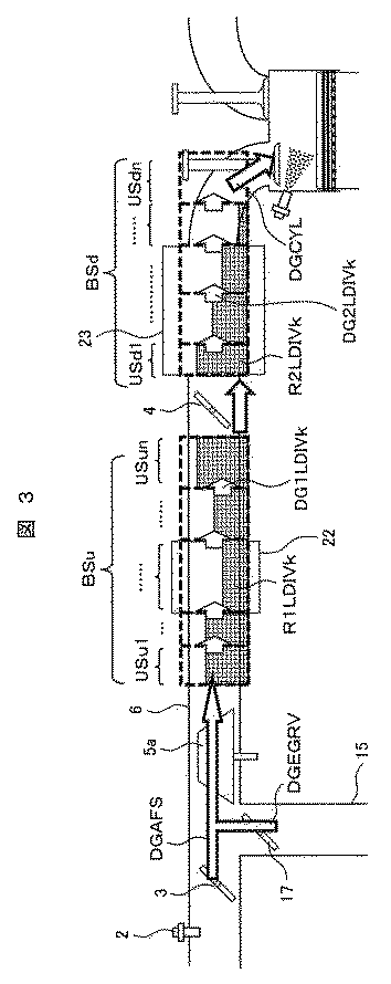
以上のような構成を備える内燃機関の制御装置において、次に本発明の第1の実施形態の具体的な構成等について説明する。図3は、本実施形態におけるEGR率を高精度に推定する考え方を説明するための概要を示している。 Next, a specific configuration and the like of the first embodiment of the present invention will be described in the control device of the internal combustion engine having the above configuration. FIG. 3 shows an outline for explaining the concept of estimating the EGR rate with high accuracy in the present embodiment.
本実施形態の基礎となる考え方は、EGRガスが吸気通路6を流れる際のEGRガスの移送状態を、吸気通路6の分割空間毎に物理モデルで記述してEGR率を推定するものであり、その物理モデルは、移流方程式を基礎として構築されている。
The basic idea of the present embodiment is to describe the transfer state of the EGR gas when the EGR gas flows through the
図3において、本実施形態では、まずスロットルバルブ4を境にして上流側空間と下流空間の2つに分割した演算領域を設定している(演算領域を形成する空間は、後述するように複数に分割された空間(分割空間)を形成する基準となるので、以下では基準空間と表記する)。そして、この2つの領域を、それぞれ上流基準空間BSuと、下流基準空間BSdとする。上流基準空間BSuは、基本的にはEGRガスの合流部からスロットルバルブ4までに設定されるが、図3では便宜的にコンプレッサ5aからスロットルバルブ4までとしている。したがって、EGRガスの合流部からコンプレッサ5aまでの領域を新たな基準空間として追加しても良いものである。更に、下流基準空間BSdは、基本的にはスロットルバルブ4から燃焼室7の入口までに設定されている。
In FIG. 3, in the present embodiment, first, a calculation area divided into two, an upstream side space and a downstream space, is set with the
そして、それぞれの基準空間BSu、BSdに存在する混合ガスのガス圧力、ガス温度、ガス質量を演算し、それぞれの基準空間BSu、BSdの各演算領域から流出する混合ガス流量を演算する。ここで求めた基準空間BSu、BSdに存在する混合ガスのガス圧力、ガス温度、ガス質量は以下に説明する中間ガス流量とEGR率を求めるのに使用されるパラメータである。 Then, the gas pressure, gas temperature, and gas mass of the mixed gas existing in the respective reference spaces BSu and BSd are calculated, and the flow rate of the mixed gas flowing out from each calculation region of the respective reference spaces BSu and BSd is calculated. The gas pressure, gas temperature, and gas mass of the mixed gas existing in the reference spaces BSu and BSd obtained here are the parameters used to obtain the intermediate gas flow rate and the EGR rate described below.
更に、本実施形態では、それぞれの基準空間BSu、BSdを、複数個の分割空間USu1〜USun、分割空間USd1〜USdn、に分割して設定する。そして、それぞれの基準空間BSu、BSdの分割空間USu1〜USun、分割空間USd1〜USdnの間を通過する混合ガスの中間流量とEGR率を、基準上流空間BSuの先頭分割空間USu1から順番に演算することで、EGRガスが燃焼室7まで到達する遅れを推定する。尚、図3に示した分割空間の境に示す「白抜き矢印」は、分割空間毎の中間ガス流量を示し、また、分割空間に示す「格子模様」は、或る時刻でのEGR率を示している。 Further, in the present embodiment, the respective reference spaces BSu and BSd are divided into a plurality of divided spaces USu1 to USun and divided spaces USd1 to USdn. Then, each reference space BSu, BSd of divided spaces USu1~USun, an intermediate flow rate and the EGR rate of the mixed gas passing between the divided space USd1~USdn, computed in order from the beginning divided space USu1 criteria upstream space BSu Therefore, the delay in reaching the combustion chamber 7 of the EGR gas is estimated. Incidentally, shown in the boundary of the divided space shown in FIG. 3, "white arrow" indicates the intermediate gas flow rate of each divided space, also "lattice pattern" shown in the divided space, the EGR rate at a certain time Shown.
図3に示す、「R1LDIV[k]」、「R2LDIV[k]」はEGR率を示し、「R1LDIV[k]」は上流基準空間BSu、「R2LDIV[k]」は下流基準空間BSdの各分割空間のEGR率を示している。同様に、「DG1LDIV[k]」、「DG2LDIV[k]」は中間ガス流量を示し、「DG1LDIV[k]」は上流基準空間BSu、「DG2LDIV[k]」は下流基準空間BSdの各分割空間の中間ガス流量を示している。ここで、[k]は、上流側から付与した分割空間の分割位置を示す番号である。また、「DGCYL」は、最終的に燃焼室に吸入される燃焼室吸入ガス流量を示している。 3, "R1LDIV [k]", "R2LDIV [k]" indicates the EGR rate, "R1LDIV [k]" upstream reference space BSu, "R2LDIV [k]" is the division of the downstream reference space BSd It shows the EGR rate in space. Similarly, "DG1LDIV [k]", "DG2LDIV [k]" indicates the intermediate gas flow rate, "DG1LDIV [k]" upstream reference space BSu, "DG2LDIV [k]" Each divided space downstream reference space BSd Shows the intermediate gas flow rate of. Here, [k] is a number indicating the division position of the division space given from the upstream side. Further, "DGCYL" indicates the flow rate of the combustion chamber intake gas that is finally sucked into the combustion chamber.
ここで、EGRガスが流れるのは、EGR配管15と吸気通路6の合流領域から燃焼室7の入口(吸気バルブの配置位置)の間である。したがって、この範囲で基準空間BS、分割空間USを分割すれば良いものである。
Here, the EGR gas flows from the confluence region of the
そして、基準空間BSの分割位置は、スロットルバルブ4、インタークーラ22、サージタンク23等の境界を分割位置とすることができる。スロットルバルブ4の配置領域では、吸気通路6の断面積が可変的に調整され、インタークーラ22、サージタンク23の配置領域では、吸気通路6の断面積が拡大されるので、これらを境として基準空間を分割すれば、演算精度が向上して望ましいものである。つまり、吸気通路6の断面積が拡大、或いは縮小する「断面積変化部分」を分割点とすれば良いものである。このように、実際の吸気通路6の形状に合わせて分割を行うことで、実際のEGR率の変動状況を模擬することができ、EGR率を高精度に推定することが可能となる。
The division position of the reference space BS can be set at the boundary between the
更に、基準空間を分割空間に分割する場合は、基本的には夫々の分割空間を等しい容積(等容積)にして分割するのが望ましい。ただ、インタークーラ22は、単一の分割空間として取り扱うのが望ましく、また、サージタンク23は複数の分割空間として取り扱うのが望ましい。ただ、これらは、吸気通路6の形態によって変わるので、インタークーラ22を複数の分割空間としたり、サージタンク23を単一の分割空間として取り扱っても良いものである。
Furthermore, when dividing the reference space into divided spaces, it is basically desirable to divide each divided space into equal volumes (equal volumes). However, it is desirable that the
また、分割空間の分割数は、吸気通路6の容積と、内燃機関に吸入される最大ガス流量に基づいて設定することも可能である。例えば、吸気通路6の容積が大きく、且つ最大ガス流量が多いほど分割空間の分割数が多く設定されるものである
次に、これらの考え方を基に、本実施形態の具体的なEGR率の推定方法を図4〜図7に基づき説明する。
Further, the number of divisions of the division space can be set based on the volume of the
図4は、本実施形態における演算ブロックを示しており、特にスロットルバルブ4の上流の上流基準空間BSuにおける演算ブロックを示している。図4に示す演算ブロックにおける各演算の詳細は、図5に示す制御フローで説明するので、図4においては、簡単に演算ブロックの説明を行なう。ここで、図4でガス流量やEGR率に「z」の符号を付しているのは、前回の演算周期で求められることを意味している。
FIG. 4 shows the calculation block in the present embodiment, and particularly shows the calculation block in the upstream reference space BSu upstream of the
尚、スロットルバルブ4の下流の下流基準空間BSdにおける演算ブロックは、図4に示す流入ガス流量を圧縮機通過流量から燃焼室吸入ガス流量に変更し、第n分割空間EGR率演算部で演算したEGR率の適用先を、スロットルバルブ上流EGR率から吸入ガスEGR率に変更したものであり、内部の演算処理は同一のため省略している。
In the calculation block in the downstream reference space BSd downstream of the
図4において、スロットル上流流入ガス流量演算部25は、質量流量計2によって計測された空気流量と、EGRバルブ17を通過するEGRガス流量から流入ガス流量を演算する。この流入ガス流量はスロットル上流圧力/温度/質量演算部26に入力され、スロットル上流圧力/温度/質量演算部26によって、上流基準空間のガス圧力、ガス温度、ガス質量が演算される。更に、ガス圧力、ガス温度、ガス質量はスロットルガス流量演算部27に入力されて、スロットルバルブ4を通過するスロットルガス流量が演算される。以上は、図5に示すステップS505〜ステップS507に対応している。
In FIG. 4, the throttle upstream inflow gas flow
また、スロットル上流流入ガス流量演算部25で演算された流入ガス流量と、先の演算タイミングで求められたスロットルガス流量は流出ガス流量として、中間ガス流量演算部28に入力される。中間ガス流量演算部28では、分割空間毎の中間ガス流量を演算している。以上は、図5に示すステップS508に対応している。
Further, the inflow gas flow rate calculated by the throttle upstream inflow gas flow
中間ガス流量演算部28からの中間ガス流量は、第1分割空間EGR質量演算部29、第2分割空間EGR質量演算部30、第n分割空間EGR質量演算部31に順次入力されていき、混合ガスの移動方向に沿って分割空間毎のEGRガス質量が順番に演算される。夫々の分割空間EGR質量演算部29〜31には、先の演算タイミングで求められた夫々の分割空間EGR率が入力され、中間ガス流量にEGR率を乗算してEGR質量を演算している。以上は、図5に示すステップS509に対応している。
The intermediate gas flow rate from the intermediate gas flow
夫々の分割空間EGR質量演算部29〜31からのEGRガス質量は、第1分割空間EGR率演算部32、第2分割空間EGR率演算部33、第n分割空間EGR率演算部34に順次入力されて、混合ガスの移動方向に沿って分割空間毎の新たなEGR率が順番に演算される。夫々の分割空間EGR率演算部32〜34には、スロットル上流圧力/温度/質量演算部26に求められた、ガス圧力、ガス温度、ガス質量が入力され、現在の混合ガス質量とEGRガス質量からEGR率を演算している。
The EGR gas masses from the respective divided space EGR
そして、最終的に第n分割空間EGR率演算部33で演算されたEGR率が、スロットルバルブ上流の現在のEGR率として確定されるようになる。以上は、図5に示すステップS510〜S513に対応している。
Finally, the EGR rate calculated by the nth division space EGR
以上に述べた演算ブロックは、実際にはマイクロコンピュータで実行されるものであり、次にこの具体的な制御フローを図5に基づき説明する。図5に示す制御フローは、過給機のコンプレッサ5aからスロットルバルブ4に至るまでの吸気通路6における、上流基準空間BSuのEGR率の推定方法について示している。尚、演算に使用するパラメータの表示において、「1」を付与しているのは、上流基準空間であることを表している。これに対して、図6においては、下流基準空間であるので「2」を付与している。
The arithmetic block described above is actually executed by a microcomputer, and then a specific control flow will be described with reference to FIG. The control flow shown in FIG. 5 shows a method of estimating the EGR rate of the upstream reference space BSu in the
まず、ステップS501では、EGR制御実行フラグが「ON」かどうかの判定を行う。EGR制御実行フラグが「OFF」の場合、ステップS502に進み、最下流の分割空間のEGR率「R1LDIVn」を「0」に設定し、ステップS513に移行する。一方、EGR制御実行フラグが「ON」の場合、ステップS503に移行する。 First, in step S501, it is determined whether or not the EGR control execution flag is “ON”. When the EGR control execution flag is "OFF", the process proceeds to step S502, the EGR rate "R1LDIVn" of the most downstream divided space is set to "0", and the process proceeds to step S513. On the other hand, when the EGR control execution flag is “ON”, the process proceeds to step S503.
ステップS503では、EGRバルブ開度「EGRSTM」とEGRバルブ前後圧「LPDP1PMS」からEGRバルブ通過EGR流量「DGEGRV」を演算する。EGRバルブ通過EGRガス流量が求まると、ステップS504に移行する。 In step S503, the EGR flow rate “DGEGRV” passing through the EGR valve is calculated from the EGR valve opening degree “EGRSTM” and the EGR valve front-rear pressure “LPDP1PMS”. When the EGR gas flow rate passing through the EGR valve is obtained, the process proceeds to step S504.
ステップS504では、質量流量計2を用いて圧力調整バルブ3を通過する空気流量「DGAFS」を計測する。空気流量が求まると、ステップS505に移行する。
In step S504, the air flow rate “DGAFS” passing through the
ステップS505では、EGRバルブ通過EGRガス流量「DGEGRV」と空気流量「DGAFS」を合計し、圧力調整バルブ3の上流の流入ガス流量(=圧縮機通過ガス流量)「DGIN1」を算出する。流入ガス流量「DGIN1」が求まると、ステップS506に移行する。
In step S505, the EGR gas flow rate “DGEGRV” passing through the EGR valve and the air flow rate “DGAFS” are summed to calculate the inflow gas flow rate (= compressor passing gas flow rate) “DGIN1” upstream of the
ステップS506では、流入ガス流量「DGIN1」と先の演算周期で演算したスロットルバルブ4の通過ガス流量「DGTHVZ」を用いて、過給機のコンプレッサ5aとスロットルバルブ4の間の吸気通路6(以下、上流基準空間)における、ガス圧力「PTHVU」、ガス温度「TTHVU」、ガス質量「MTHVU」を演算する。ガス圧力「PTHVU」、ガス温度「TTHVU」、ガス質量「MTHVU」が求まると、ステップS507に移行する。
In step S506, the intake passage 6 (hereinafter referred to as the intake passage 6) between the
ステップS507では、ガス圧力「PTHVU」、ガス温度「TTHVU」、ガス質量「MTHVU」を用いて現在のスロットルバルブ4の通過ガス流量「DGTHV」を演算する。尚、ステップS506、S507の演算は公知の方法で良いため、詳細な説明は省略する。スロットルバルブ4の通過ガス流量「DGTHV」が求まると、ステップS508に移行する。
In step S507, the current passing gas flow rate “DGTHV” of the
ステップS508では、以下の(1)式に基づき、流入ガス流量「DGIN1」、スロットルバルブ4の通過ガス流量「DGTHV」を用いて、上流基準空間の分割空間の中間ガス流量「DG1LDIV[k]」を演算する。
In step S508, the intermediate gas flow rate “DG1LDIV [k]” of the divided space of the upstream reference space is used by using the inflow gas flow rate “DGIN1” and the passing gas flow rate “DGTHV” of the
ここで、(1)式中の「n」は分割空間の分割数、「k」は各分割空間の分割位置を示す番号である。つまり、(1)式は、k=1〜nまでの各分割空間の現在の中間ガス流量「DG1LDIV[k]」の演算を順番に実行するものである。中間ガス流量「DG1LDIV[k]」が求まると、ステップS509に移行する。 Here, "n" in the equation (1) is the number of divisions in the division space, and "k" is a number indicating the division position of each division space. That is, the equation (1) sequentially executes the calculation of the current intermediate gas flow rate “DG1LDIV [k]” of each divided space from k = 1 to n. When the intermediate gas flow rate “DG1LDIV [k]” is obtained, the process proceeds to step S509.
ステップS509では、以下の(2)式に基づき、中間ガス流量「DG1LDIV[k]」と先の演算周期で演算した分割空間のEGR率「R1LDIVZ[k]」を用いて、現在の分割空間のEGR質量「MEGR1LDIV[k]」を演算する。尚、上述のパラメータの「Z」は、前回の演算周期での演算値であることを示し、また、(2)式の[k−1]は、演算対象の分割空間の上流の分割空間の値を意味するものである。 In step S509, based on the following equation (2), the intermediate gas flow rate “DG1LDIV [k]” and the EGR rate “R1LDIVZ [k]” of the divided space calculated in the previous calculation cycle are used to obtain the current divided space. The EGR mass "MEGR1LDIV [k]" is calculated. The above-mentioned parameter "Z" indicates the calculated value in the previous calculation cycle, and [k-1] in Eq. (2) is the divided space upstream of the divided space to be calculated. It means a value.
分割空間のEGR質量「MEGR1LDIV[k]」が求まると、ステップS510に移行する。 When the EGR mass “MEGR1LDIV [k]” of the divided space is obtained, the process proceeds to step S510.
ステップS510では、以下の(3)式に基づき、ステップS506で求めたガス質量「MTHVU」を分割数「n」で分割(=除算)して、分割空間のガス質量「MALL1LDIV」を演算する。 In step S510, the gas mass “MTHVU” obtained in step S506 is divided (= divided) by the number of divisions “n” based on the following equation (3), and the gas mass “MALL1LDIV” in the divided space is calculated.
分割空間のガス質量「MALL1LDIV」が求まると、ステップS511に移行する。 When the gas mass "MALL1LDIV" in the divided space is obtained, the process proceeds to step S511.
ステップS511では、分割空間のEGR質量「MEGR1LDIV」と分割空間のガス質量「MALL1LDIV」を用いて、分割空間のEGR率「R1LDIV[k]」を演算する。分割空間のEGR率「R1LDIV[k]」が求まると、ステップS512に移行する。 In step S511, using a gas mass "MALL1LDIV" of the EGR mass "MEGR1LDIV" and divided space divided space, calculates the EGR rate of the divided spaces "R1LDIV [k]". When the EGR rate “R1LDIV [k]” of the divided space is obtained, the process proceeds to step S512.
ステップS512では、すべての分割空間におけるEGR率「R1LDIV[k]」が演算されたか判定を行う。すなわち「k=1」から「k=n」までの分割空間のEGR率「R1LDIV[k]」がすべて演算されていれば処理を終了する。演算されていない分割空間が存在すれば、該当の分割空間でステップS508からS511の処理を実行する。上述したステップS502、又はステップSS512の処理が終了すると、ステップS513に移行する。 In step S512, it is determined whether the EGR rate “R1LDIV [k]” in all the divided spaces has been calculated. That is, if all the EGR ratios "R1LDIV [k]" of the divided space from "k = 1" to "k = n" have been calculated, the process ends. If there is operation that is not divided space, and executes processing from step S508 in the divided space of the corresponding S511. When the process of step S502 or step SS512 described above is completed, the process proceeds to step S513.
ステップS513では、最下流の分割空間のEGR率「R1LDIV「n」」をスロットルバルブ4の上流基準空間のEGR率「RTHV」として、今回の演算周期での処理を終了し、次の演算周期以降、同様の処理をECU19が停止するまで繰り返すことになる。
In step S513, the EGR rate “R1LDIV“ n ”” of the most downstream divided space is set as the EGR rate “RTHV” of the upstream reference space of the
以上の説明は、スロットルバルブ4より上流の上流基準空間BSuに関するものであるが、次にスロットルバルブ4より下流の下流基準空間BSdに関する説明を行なうことにする。図6に示す制御フローは、スロットルバルブ4から燃焼室7に至るまでの吸気通路6における、下流基準空間BSdのEGR率の推定方法について示している。尚、演算に使用するパラメータの表示において、上述した通り「2」を付与しているのは、下流基準空間であることを表している。
The above description relates to the upstream reference space BSd upstream of the
ステップS601では、図5のステップS501と同じ判定処理を実行する。EGR実行フラグが「OFF」の場合は、ステップS602に移行してEGR率を「0」としてステップS611に移行する。一方、EGR制御実行フラグが「ON」の場合は、ステップS603に移行する。 In step S601, the same determination process as in step S501 of FIG. 5 is executed. When the EGR execution flag is "OFF", the process proceeds to step S602, the EGR rate is set to "0", and the process proceeds to step S611. On the other hand, when the EGR control execution flag is “ON”, the process proceeds to step S603.
ステップS603では、先の演算周期に演算したスロットルバルブ通過ガス流量「DGTHVZ」、燃焼室吸入ガス流量「DGCYLZ」を読み出し、ステップS604に移行する。尚、上述のパラメータの「Z」は、前回の演算周期での演算値であることを示している。 In step S603, the throttle valve passing gas flow rate “DGTHVZ” and the combustion chamber intake gas flow rate “DGCYLZ” calculated in the previous calculation cycle are read out, and the process proceeds to step S604. The above-mentioned parameter "Z" indicates that it is a calculated value in the previous calculation cycle.
そして、ステップS604からステップS610は、図5のステップS506からステップS512の演算における、流入ガス流量「DGIN1」をスロットルバルブ通過ガス流量「DGTHVZ」に変更し、スロットルバルブ通過ガス流量「DGTHVZ」を燃焼室吸入ガス流量「DGCYL」に変更した処理と同じのため、詳細な説明は省略する。 Then, in steps S604 to S610, the inflow gas flow rate "DGIN1" in the calculation from step S506 to step S512 in FIG. 5 is changed to the throttle valve passing gas flow rate "DGTHVZ", and the throttle valve passing gas flow rate "DGTHVZ" is burned. Since it is the same as the process changed to the chamber intake gas flow rate "DGCYL", detailed description thereof will be omitted.
尚、ステップS605では、ステップS604で求めたガス圧力「PIMANI」、ガス温度「TIMANI」、ガス質量「MIMANI」、吸気バルブ開時期「IVTC」、排気バルブ開時期「EVTC」、回転数「NE」から燃焼室吸入ガス流量「DGCYL」を算出している。尚、ステップS604、S605の演算は公知の方法で良いため、詳細な説明は省略する。上述したステップS602、又はステップSS610の処理が終了すると、ステップS611に移行する。 In step S605, the gas pressure "PIMANI", the gas temperature "TIMANI", the gas mass "MIMANI", the intake valve opening time "IVTC", the exhaust valve opening time "EVTC", and the rotation speed "NE" obtained in step S604 were obtained. The combustion chamber intake gas flow rate "DGCYL" is calculated from. Since the calculation in steps S604 and S605 may be performed by a known method, detailed description thereof will be omitted. When the process of step S602 or step SS610 described above is completed, the process proceeds to step S611.
ステップS611では、最下流の分割空間のEGR率「R2LDIV「n」」をスロットルバルブ4の下流基準空間の燃焼室7に吸入される吸入ガスEGR率「RCYL」として、今回の演算周期での処理を終了し、次の演算周期以降、同様の処理をECUが停止するまで繰り返すことになる。
In step S611, the EGR rate "R2LDIV" n "" in the most downstream divided space is set as the intake gas EGR rate "RCYL" sucked into the combustion chamber 7 in the downstream reference space of the
図5、図6からわかるように、吸気通路を複数に分割し、分割空間の中間ガス流量と基準空間の流量から演算して、順番にEGR率を演算することで、EGR率の過渡応答を高精度に推定することが可能となる。 As can be seen from FIGS. 5 and 6 , the transient response of the EGR rate is obtained by dividing the intake passage into a plurality of parts, calculating from the intermediate gas flow rate in the divided space and the flow rate in the reference space, and calculating the EGR rate in order. It is possible to estimate with high accuracy.
図7は、従来のEGR率推定方法と本実施形態になるEGR率推定方法による推定結果を比較したものである。図7の(A)、及び(B)は、従来の推定方法でEGR率を推定した結果を示し、図7の(C)は、本実施形態の推定方法でEGR率を推定した結果を示している。 FIG. 7 compares the estimation results of the conventional EGR rate estimation method and the EGR rate estimation method of the present embodiment. (A) and (B) of FIG. 7 show the result of estimating the EGR rate by the conventional estimation method, and FIG. 7 (C) shows the result of estimating the EGR rate by the estimation method of the present embodiment. ing.
尚、それぞれの図の上側はEGR率の変化を示し、実線が実際のEGR率を示し、破線が推定EGR率を示している。また、下側はスロットルバルブ及びEGRバルブの開度変化を示している。実際は異なるバルブだが、ここでは同時に閉じた場合を示すため、重ねて1本の実線で示している。 The upper side of each figure shows the change in the EGR rate, the solid line shows the actual EGR rate, and the broken line shows the estimated EGR rate. The lower side shows changes in the opening degrees of the throttle valve and the EGR valve. Although they are actually different valves, they are shown by one solid line in an overlapping manner to show the case where they are closed at the same time.
図7の(A)、(B)、(C)において、EGRバルブが開かれると、EGRガスが遅れを伴い基準空間の出口に到達する。このため、EGR率は基準空間の入口と出口で異なる変化となる。更に、出口ではEGRガスが滞留してEGR率の上昇が生じる等の入口とは異なる変化となっている。 In FIGS. 7A, 7B, and 7C, when the EGR valve is opened, the EGR gas reaches the outlet of the reference space with a delay. Therefore, the EGR rate changes differently at the entrance and exit of the reference space. Further, at the outlet, the EGR gas stays and the EGR rate rises, which is a change different from that at the inlet.
そして、図7の(A)では、基準空間の代表EGR率を推定するものであるため、入口と出口の区別がなく応答の遅れを模擬することができないものである。そこで、図7の(B)では、遅れを時定数で設定したものであるが、この場合は、出口での滞留状態を推定することができないものである。 Then, in FIG. 7A, since the representative EGR rate of the reference space is estimated, there is no distinction between the inlet and the outlet, and the response delay cannot be simulated. Therefore, in FIG. 7B, the delay is set by a time constant, but in this case, the retention state at the exit cannot be estimated.
一方、本実施形態のEGR率推定方法においては、移流方程式を利用して、基準空間のガス流量から中間ガス流量を演算し、その結果を用いてEGR率の推定演算を行うことで、実際のEGR率の遅れの挙動を模擬することが可能となり、正確なEGR率を推定することができるようになる。 On the other hand, in the EGR rate estimation method of the present embodiment, the intermediate gas flow rate is calculated from the gas flow rate in the reference space by using the convection equation, and the EGR rate is estimated by using the result. It becomes possible to simulate the behavior of the delay of the EGR rate, and it becomes possible to estimate the accurate EGR rate.
上述した第1の実施形態は、正確なEGR率の推定を行なう推定方法を提案したものであるが、本発明の第2の実施形態では、演算した燃焼室吸入ガス流量「DGCYL」と吸入ガスEGR率「RCYL」を用いて燃料噴射量、及び点火時期を補正する制御を提案するものである。 The first embodiment described above proposes an estimation method for accurately estimating the EGR rate, but in the second embodiment of the present invention, the calculated combustion chamber intake gas flow rate “DGCYL” and the intake gas It proposes a control for correcting the fuel injection amount and the ignition timing by using the EGR rate "RCYL".
図8は、燃料噴射量と点火時期の演算を行う機能ブロックを示しており、燃焼室吸入ガス流量「DGCYL」と吸入ガスEGR率「RCYL」が、吸入空気流量演算部40に入力され、燃焼室内の吸入空気量を演算する。求められた吸入空気量は、燃料噴射量演算部41と基準点火時期演算部42に入力される。
FIG. 8 shows a functional block that calculates the fuel injection amount and the ignition timing, and the combustion chamber intake gas flow rate “DGCYL” and the intake gas EGR rate “RCYL” are input to the intake air flow
また、燃料噴射量演算部41には、回転数やこれ以外の種々の補正情報も入力されており、これらを基に燃料噴射量が演算される。また、基準点火時期演算部42には、回転数が入力されており、これを基に基準点火時期が演算される。また、吸入ガスEGR率「RCYL」と回転数が進角点火時期演算部43に入力され、点火時期の補正点火時期を演算する。基準点火時期と補正点火時期は点火時期演算部44に入力されて、最終的な点火時期が演算される。尚、燃料噴射量や点火時期は、上述した入力情報だけでなく、種々の補正情報によって補正されることはいうまでもない。
Further, the number of revolutions and various other correction information are also input to the fuel injection
次に、以上に述べた演算ブロックの具体的な制御フローを図9、図10に基づき説明する。図9は、燃料噴射量を制御する場合の制御フローを示しており、図10は、点火時期を制御する場合の制御フローを示している。まず、燃料噴射量を制御する場合の制御フローを説明する。 Next, the specific control flow of the calculation block described above will be described with reference to FIGS. 9 and 10. FIG. 9 shows a control flow when controlling the fuel injection amount, and FIG. 10 shows a control flow when controlling the ignition timing. First, a control flow for controlling the fuel injection amount will be described.
ステップS901では、以下の(4)式に基づいて、吸入ガスEGR率「RCYL」と、燃焼室吸入ガス流量「DGCYL」を用いて吸入空気流量「DGCYLAIR」を演算する。 In step S901, the intake air flow rate “DGCYLAIR” is calculated using the intake gas EGR rate “RCYL” and the combustion chamber intake gas flow rate “DGCYL” based on the following equation (4).
吸入空気流量「DGCYLAIR」が求まると、ステップS902に移行する。 When the intake air flow rate “DGCYLAIR” is obtained, the process proceeds to step S902.
ステップS902では、以下の(5)式に基づいて、吸入空気流量「DGCYLAIR」から燃料噴射量「MFUEL」を演算する。 In step S902, the fuel injection amount “MFUEL” is calculated from the intake air flow rate “DGCYLAIR” based on the following equation (5).
この燃料噴射量「MFUEL」は、図示しない演算ブロックで演算された目標当量比「TABFC」を用いて演算されている。燃料噴射量「MFUEL」が求まると、ステップS903に移行する。 This fuel injection amount "MFUEL" is calculated using the target equivalent ratio "TABFC" calculated by a calculation block (not shown). When the fuel injection amount “MFUEL” is obtained, the process proceeds to step S903.
ステップS903では、燃料噴射量「MFUEL」をインジェクタ駆動回路から燃料噴射弁8に送信して実際の燃料噴射を実行する。尚、実際に燃料噴射弁に送信する信号は、燃料噴射弁8の開弁期間であるが、燃料噴射量「MFUEL」から開弁期間への変換は公知であるため、説明は省略する。
In step S903, the fuel injection amount “MFUEL” is transmitted from the injector drive circuit to the
次に、図10に基づき点火時期を制御する場合の制御フローを説明する。 Next, a control flow in the case of controlling the ignition timing based on FIG. 10 will be described.
ステップS1001では、吸入空気量「DGCYLAIR」に基づいて基準点火時期「STD」を演算する。ここでは、吸入空気量「DGCYLAIR」と基準点火時期「STD」を事前に対応づけた、データテーブルを用いて読み出すように構成されている。基準点火時期「STD」が求まると、ステップS1002に移行する。 In step S1001, the reference ignition timing “STD” is calculated based on the intake air amount “DGCYLAIR”. Here, it is configured to read out using a data table in which the intake air amount “DGCYLAIR” and the reference ignition timing “STD” are associated in advance. When the reference ignition timing “STD” is obtained, the process proceeds to step S1002.
ステップS1002では、吸入ガスEGR率「RCYL」から補正点火時期「EGRADV」を演算する。尚、補正点火時期「EGRADV」も図11に示すように、吸入ガスEGR率「RCYL」と対応づけた、データテーブルから読み取ることで演算される。このテーブルでは、燃焼室に吸入される混合ガスのEGR率が高いほど、点火時期を最適時期(例えば、MBT)に向けて進角される特性とされている。つまり、吸入ガスEGR率が大きいほど点火時期を最適点火時期に向けて進角し、吸入ガスEGR率が小さいほど点火時期を遅角するように構成されている。補正点火時期「EGRADV」が求まると、ステップS1003に移行する。 In step S1002, the corrected ignition timing “EGRADV” is calculated from the intake gas EGR rate “RCYL”. As shown in FIG. 11, the corrected ignition timing “EGRADV” is also calculated by reading from the data table associated with the intake gas EGR rate “RCYL”. In this table, the higher the EGR ratio of the mixed gas taken into the combustion chamber, the more the ignition timing is advanced toward the optimum timing (for example, MBT). That is, the larger the intake gas EGR rate is, the more the ignition timing is advanced toward the optimum ignition timing, and the smaller the intake gas EGR rate is, the more the ignition timing is retarded. When the corrected ignition timing "EGRADV" is obtained, the process proceeds to step S1003.
ステップS1003では、減速中で、かつ吸入ガスEGR率「RCYL」が閾値以上であるかどうかの判定を実行する。減速中で、かつ吸入ガスEGR率「RCYL」が閾値以上である場合はステップS1004に移行する。一方、減速中で、かつ吸入ガスEGR率「RCYL」が閾値以上でない場合はステップS1005に移行する。 In step S1003, it is determined whether or not the deceleration is in progress and the intake gas EGR rate "RCYL" is equal to or higher than the threshold value. If the vehicle is decelerating and the intake gas EGR rate “RCYL” is equal to or higher than the threshold value, the process proceeds to step S1004. On the other hand, if the vehicle is decelerating and the intake gas EGR rate "RCYL" is not equal to or higher than the threshold value, the process proceeds to step S1005.
ステップS1004では、点火時期を所定時間だけ遅角しないようにするため、前回の演算周期の補正点火時期「EGRADV」を保持して補正点火時期「EGRADV」とする。一方、ステップS1005では、ステップS1001で演算した基準点火時期「STD」に補正点火時期「EGRADV」を加算して最終点火時期「FADVS」を演算する。更に、ステップS1006では、最終点火時期「FADVS」に基づき、それぞれの燃焼周期毎に点火信号出力回路から点火プラグに点火信号を送信する。 In step S1004, in order to prevent the ignition timing from being retarded by a predetermined time, the corrected ignition timing "EGRADV" of the previous calculation cycle is held and set to the corrected ignition timing "EGRADV". On the other hand, in step S1005, the correction ignition timing "EGRADV" is added to the reference ignition timing "STD" calculated in step S1001 to calculate the final ignition timing "FADVS". Further, in step S1006, an ignition signal is transmitted from the ignition signal output circuit to the spark plug for each combustion cycle based on the final ignition timing "FADVS".
図12は、本実施形態における吸入ガスEGR率「RCYL」に合わせた点火時期及び燃料噴射量の制御状態を示している。 FIG. 12 shows the control state of the ignition timing and the fuel injection amount according to the intake gas EGR rate “RCYL” in the present embodiment.
減速時において、スロットルバルブ4及びEGRバルブ17を閉じたとすると、吸入空気流量とEGRガス流量が低下する。これに伴って、燃焼室内への燃焼室吸入ガス流量、及び吸入空気流量も減少する。ここでEGR率の変化と空気流量の変化の応答性に差があるため、空気とEGRガスの混合気体の流量である燃焼室吸入ガス流量から、EGRガス流量を減算することで、実際の吸入空気流量を演算することができ、燃料噴射量は、この空気流量を基に目標空燃比を反映させて算出することができる。
If the
一方、EGR率は、推定した吸入ガスEGR率「RCYL」に加えて内部EGR率(残留ガス率)との組み合わせで高いEGR率となるため、点火時期を急速に遅角すると失火する可能性がある。そのため、ステップS1004にある通り、所定時間、又はEGR率が一定量以下になるまで、点火時期を進角状態で所定期間ΔTだけ維持する。この所定期間ΔTを経過すると、吸入ガスEGR率「RCYL」に合せて徐々に点火時期を遅角方向に移行させていくようにする。 On the other hand, the EGR rate becomes a high EGR rate in combination with the estimated intake gas EGR rate "RCYL" and the internal EGR rate (residual gas rate), so there is a possibility of misfire if the ignition timing is rapidly retarded. be. Therefore, as described in step S1004, the ignition timing is maintained for a predetermined period ΔT in the advanced angle state until the predetermined time or the EGR rate becomes a certain amount or less. After this predetermined period ΔT has elapsed, the ignition timing is gradually shifted in the retard direction according to the intake gas EGR rate “RCYL”.
本実施形態の燃料噴射制御によれば、適切な空燃比を実現でき、EGRガスが導入されても排気有害成分の増大を防止することが可能となる。また、本実施形態の点火時期制御によれば、通常時はEGR率に合わせて点火時期を設定することで異常燃焼を避けながら低燃費化を図ることができ、更に、減速時は推定が困難な内部EGR率の増加による失火を避けることができるようになる。 According to the fuel injection control of the present embodiment, an appropriate air-fuel ratio can be realized, and even if EGR gas is introduced, it is possible to prevent an increase in exhaust harmful components. Further, according to the ignition timing control of the present embodiment, it is possible to improve fuel efficiency while avoiding abnormal combustion by setting the ignition timing according to the EGR rate in the normal state, and it is difficult to estimate during deceleration. It becomes possible to avoid misfire due to an increase in the internal EGR rate.
以上述べた通り、本発明によれば、吸入空気とEGRガスの混合ガスが流れる流線に沿って吸気通路の基準空間を複数に分割して分割空間を形成し、夫々の分割空間に対応して混合ガスのEGR率を推定するための移流方程式に基づく物理モデルを構築し、この物理モデルによって、先頭の分割空間からこれに繋がる分割空間のEGR率を順番に推定して燃焼室に流入するEGR率を推定する構成とした。これによれば、内燃機関の運転状態が種々変化する過渡状態おいても、高精度にEGR率を推定することができる。 As described above, according to the present invention, the reference space of the intake passage along the flow line through which a mixed gas of intake air and the EGR gas is divided into a plurality to form a divided space, corresponding to the divided respective spaces the EGR rate of the mixed gas to build a physical model based on the advection equation for estimating Te, this physical model, the EGR rate of the divided spaces leading from the head of the divided space to be estimated in order to flow into the combustion chamber The configuration was such that the EGR rate was estimated. According to this, the EGR rate can be estimated with high accuracy even in a transient state in which the operating state of the internal combustion engine changes variously.
尚、本発明は上記した実施例に限定されるものではなく、様々な変形例が含まれる。例えば、上記した実施例は本発明を分かりやすく説明するために詳細に説明したものであり、必ずしも説明した全ての構成を備えるものに限定されるものではない。また、ある実施例の構成の一部を他の実施例の構成に置き換えることが可能であり、また、ある実施例の構成に他の実施例の構成を加えることも可能である。また、各実施例の構成の一部について、他の構成の追加・削除・置換をすることが可能である。 The present invention is not limited to the above-described embodiment, and includes various modifications. For example, the above-described embodiment has been described in detail in order to explain the present invention in an easy-to-understand manner, and is not necessarily limited to those having all the described configurations. Further, it is possible to replace a part of the configuration of one embodiment with the configuration of another embodiment, and it is also possible to add the configuration of another embodiment to the configuration of one embodiment. Further, it is possible to add / delete / replace a part of the configuration of each embodiment with another configuration.
1…内燃機関、2…質量流量計、3…圧力調整バルブ、4…スロットルバルブ、5a…コンプレッサ、6…吸気通路、7…燃焼室、8…燃料噴射弁、9…点火プラグ、10…三元触媒、11…空燃比センサ、12…排気マニフォルド、13…排気管、14…第2三元触媒、15…EGR配管、16…EGRクーラ、17…EGRバルブ、18…圧力センサ、19…コントロールユニット、20…アクセル開度センサ、22…インタークーラ、23…サージタンク、BSu…上流基準空間、BSd…下流基準空間、USu1〜USun…分割空間、USd1〜USdn…分割空間、25…スロットル上流流入ガス流量演算部、26…スロットル上流圧力/温度/質量演算部、27…スロットルガス流量演算部、28…中間ガス流量演算部、29、30、31…分割空間EGRガス質量演算部、32、33、34…分割空間EGR率演算部。 1 ... Internal combustion engine, 2 ... Mass flow meter, 3 ... Pressure adjustment valve, 4 ... Throttle valve, 5a ... Compressor, 6 ... Intake passage, 7 ... Combustion chamber, 8 ... Fuel injection valve, 9 ... Ignition plug, 10 ... 3 Original catalyst, 11 ... Air fuel ratio sensor, 12 ... Exhaust manifold, 13 ... Exhaust pipe, 14 ... Second ternary catalyst, 15 ... EGR piping, 16 ... EGR cooler, 17 ... EGR valve, 18 ... Pressure sensor, 19 ... Control Unit, 20 ... Accelerator opening sensor, 22 ... Intercooler, 23 ... Surge tank, BSu ... Upstream reference space, BSd ... Downstream reference space, USu1-USun ... Divided space, USd1-USdn ... Divided space, 25 ... Throttle upstream inflow Gas flow rate calculation unit, 26 ... Throttle upstream pressure / temperature / mass calculation unit, 27 ... Throttle gas flow rate calculation unit, 28 ... Intermediate gas flow rate calculation unit, 29, 30, 31 ... Divided space EGR gas mass calculation unit, 32, 33 , 34 ... Divided space EGR rate calculation unit.
Claims (8)
前記EGR率推定手段は、
前記吸気通路と前記排気ガス再循環通路の接続部分より後流の前記吸気通路の所定の空間を混合ガスが流れる流線に沿って複数に分割した分割空間を形成し、夫々の前記分割空間に対応して混合ガスのEGR率を推定するための移流方程式に基づく物理モデルを構築し、前記物理モデルによって、先頭の前記分割空間からこれに繋がる後続の前記分割空間のEGR率を順番に推定して前記燃焼室に流入する混合ガスの最終的なEGR率を推定するものであり、
更に前記EGR率推定手段は、
前記所定の空間のガス質量を前記分割空間の個数で除算して、前記分割空間の分割空間ガス質量を演算する分割空間ガス質量演算部と、
前記所定の空間の今回の演算で求めた入口の流入ガス流量と前回の演算で求めた入口の流入ガス流量である出口の流出ガス流量に基づいて、夫々の前記分割空間における中間ガス流量を演算する中間ガス流量演算部と、
前記中間ガス流量演算部で求められた中間ガス流量とEGR率とから、夫々の前記分割空間の分割空間EGRガス質量を求める分割空間EGRガス質量演算部と、
前記分割空間ガス質量演算部で求められた分割空間ガス質量と、前記分割空間EGRガス質量演算部で求められた分割空間EGRガス質量とに基づいて、混合ガスの新たなEGR率を先頭の前記分割空間から順番に演算する分割空間EGR率演算部と
から構成されていることを特徴とする内燃機関の制御装置。 An intake passage that is connected to the combustion chamber and supplies intake air to the combustion chamber, an exhaust gas recirculation passage that is connected to the intake passage and recirculates exhaust gas (hereinafter referred to as EGR gas), and the intake air. It is used in an internal combustion engine equipped with a throttle valve that is arranged in the intake passage that is wake from the connection portion between the passage and the exhaust gas recirculation passage and that controls the flow rate of the mixed gas in which the intake air and the EGR gas are mixed. EGR rate estimation means for estimating the ratio of mixed gas and EGR gas supplied to the chamber (hereinafter referred to as EGR rate) and injection from a fuel injection valve provided in the combustion chamber using the estimated EGR rate. In a control device of an internal combustion engine provided with a control means having a fuel injection control means for controlling an amount of fuel injection to be performed.
The EGR rate estimation means is
A predetermined space of the intake passage that is wake from the connection portion between the intake passage and the exhaust gas recirculation passage is divided into a plurality of divided spaces along the streamline through which the mixed gas flows, and each of the divided spaces is divided. the EGR rate of the mixed gas in response to construct a physical model based on the advection equation to estimate the, by the physical model, estimate a first EGR rate of subsequent said divided spaces connected thereto from the divided space in order The final EGR rate of the mixed gas flowing into the combustion chamber is estimated.
Further, the EGR rate estimation means is
A divided space gas mass calculation unit that calculates the divided space gas mass of the divided space by dividing the gas mass of the predetermined space by the number of the divided spaces.
Calculate the intermediate gas flow rate in each of the divided spaces based on the inflow gas flow rate at the inlet obtained in this calculation of the predetermined space and the outflow gas flow rate at the outlet which is the inflow gas flow rate at the inlet obtained in the previous calculation. Intermediate gas flow rate calculation unit and
From the intermediate gas flow rate and the EGR rate obtained by the intermediate gas flow rate calculation unit, the division space EGR gas mass calculation unit for obtaining the division space EGR gas mass of each of the division spaces, and the division space EGR gas mass calculation unit.
Based on the divided space gas mass obtained by the divided space gas mass calculation unit and the divided space EGR gas mass obtained by the divided space EGR gas mass calculation unit, a new EGR ratio of the mixed gas is added to the head. With the division space EGR rate calculation unit that calculates in order from the division space
A control device for an internal combustion engine, which is characterized by being composed of.
前記所定の空間は、前記吸気通路の断面積が拡大、或いは縮小する断面積変化部分を境にして設定されているThe predetermined space is set with a cross-sectional area change portion in which the cross-sectional area of the intake passage is expanded or contracted as a boundary.
ことを特徴とする内燃機関の制御装置。A control device for an internal combustion engine.
前記分割空間の容積は、それぞれ等しい容積に設定されているThe volumes of the divided spaces are set to equal volumes.
ことを特徴とする内燃機関の制御装置。A control device for an internal combustion engine.
前記吸気通路の途中にはインタークーラ、或いはサージタンクが設けられており、前記インタークーラ、或いは前記サージタンクは、単独で前記分割空間として設定されるか、或いは複数の前記分割空間として設定されるAn intercooler or a surge tank is provided in the middle of the intake passage, and the intercooler or the surge tank is independently set as the divided space or is set as a plurality of the divided spaces.
ことを特徴とする内燃機関の制御装置。A control device for an internal combustion engine.
前記分割空間の分割数は、前記吸気通路の前記所定の空間の容積と前記内燃機関に吸入される最大ガス流量に基づいて設定されるThe number of divisions of the divided space is set based on the volume of the predetermined space of the intake passage and the maximum gas flow rate sucked into the internal combustion engine.
ことを特徴とする内燃機関の制御装置。A control device for an internal combustion engine.
前記所定の空間は、前記吸気通路に設けられた前記スロットルバルブを境にして、前記スロットルバルブとEGRガスが導入される領域までの上流空間と、前記スロットルバルブと前記燃焼室の入口までの下流空間とに設定されており、The predetermined space is an upstream space to a region where the throttle valve and the EGR gas are introduced, and a downstream to the inlet of the throttle valve and the combustion chamber, with the throttle valve provided in the intake passage as a boundary. It is set to space and
前記上流空間の最後部の前記分割空間のEGR率が、前記下流空間の先頭部の前記分割空間のEGR率として設定されるThe EGR rate of the divided space at the end of the upstream space is set as the EGR rate of the divided space at the beginning of the downstream space.
ことを特徴とする内燃機関の制御装置。A control device for an internal combustion engine.
前記制御手段は、前記燃焼室の混合気に点火する点火制御手段を有しており、前記点火制御手段は、前記燃焼室に吸入された混合ガスの最終的なEGR率が大きいほど点火時期を最適点火時期に向けて進角し、最終的なEGR率が小さいほど前記点火時期を遅角するThe control means has an ignition control means for igniting the air-fuel mixture in the combustion chamber, and the ignition control means determines the ignition timing as the final EGR ratio of the mixed gas sucked into the combustion chamber increases. It advances toward the optimum ignition timing, and the smaller the final EGR rate, the more the ignition timing is retarded.
ことを特徴とする内燃機関の制御装置。A control device for an internal combustion engine.
前記点火制御手段は、前記スロットルバルブが閉じられ混合ガス流量が減少された場合において、最終的なEGR率が所定の閾値以上であると所定時間だけこの時の前記点火時期を維持し、最終的なEGR率が前記所定の閾値以下であると最終的なEGR率に基づく補正点火時期によって前記点火時期を調整するWhen the throttle valve is closed and the mixed gas flow rate is reduced, the ignition control means maintains the ignition timing at this time for a predetermined time when the final EGR rate is equal to or higher than a predetermined threshold, and finally. When the EGR rate is equal to or less than the predetermined threshold value, the ignition timing is adjusted by the corrected ignition timing based on the final EGR rate.
ことを特徴とする内燃機関の制御装置。A control device for an internal combustion engine.
Priority Applications (4)
| Application Number | Priority Date | Filing Date | Title |
|---|---|---|---|
| JP2017125947A JP6943643B2 (en) | 2017-06-28 | 2017-06-28 | Internal combustion engine control device |
| US16/624,446 US10920683B2 (en) | 2017-06-28 | 2018-06-04 | Control device for internal combustion engine |
| DE112018002483.0T DE112018002483T5 (en) | 2017-06-28 | 2018-06-04 | CONTROL DEVICE FOR AN INTERNAL COMBUSTION ENGINE |
| PCT/JP2018/021312 WO2019003806A1 (en) | 2017-06-28 | 2018-06-04 | Internal combustion engine control device |
Applications Claiming Priority (1)
| Application Number | Priority Date | Filing Date | Title |
|---|---|---|---|
| JP2017125947A JP6943643B2 (en) | 2017-06-28 | 2017-06-28 | Internal combustion engine control device |
Publications (2)
| Publication Number | Publication Date |
|---|---|
| JP2019007460A JP2019007460A (en) | 2019-01-17 |
| JP6943643B2 true JP6943643B2 (en) | 2021-10-06 |
Family
ID=64741543
Family Applications (1)
| Application Number | Title | Priority Date | Filing Date |
|---|---|---|---|
| JP2017125947A Active JP6943643B2 (en) | 2017-06-28 | 2017-06-28 | Internal combustion engine control device |
Country Status (4)
| Country | Link |
|---|---|
| US (1) | US10920683B2 (en) |
| JP (1) | JP6943643B2 (en) |
| DE (1) | DE112018002483T5 (en) |
| WO (1) | WO2019003806A1 (en) |
Families Citing this family (1)
| Publication number | Priority date | Publication date | Assignee | Title |
|---|---|---|---|---|
| US11313291B2 (en) * | 2020-08-03 | 2022-04-26 | GM Global Technology Operations LLC | Secondary throttle control systems and methods |
Family Cites Families (11)
| Publication number | Priority date | Publication date | Assignee | Title |
|---|---|---|---|---|
| JP3888024B2 (en) * | 2000-03-31 | 2007-02-28 | 三菱自動車工業株式会社 | Exhaust gas recirculation device |
| JP3988035B2 (en) * | 2002-06-11 | 2007-10-10 | 三菱自動車工業株式会社 | EGR rate estimation device for internal combustion engine |
| JP5062133B2 (en) * | 2008-10-15 | 2012-10-31 | トヨタ自動車株式会社 | Ignition timing control device for internal combustion engine |
| JP5907339B2 (en) | 2011-05-27 | 2016-04-26 | 株式会社デンソー | In-cylinder inflow EGR gas flow rate estimation device for internal combustion engine |
| JP5854328B2 (en) * | 2011-05-27 | 2016-02-09 | 株式会社デンソー | Control device for internal combustion engine |
| JP5673356B2 (en) | 2011-05-27 | 2015-02-18 | 株式会社デンソー | Control device for internal combustion engine |
| JP5585942B2 (en) * | 2011-05-27 | 2014-09-10 | 株式会社デンソー | Control device for internal combustion engine |
| JP2014001666A (en) * | 2012-06-18 | 2014-01-09 | Toyota Motor Corp | Control device of internal combustion engine |
| JP6221321B2 (en) | 2013-04-17 | 2017-11-01 | 株式会社デンソー | Control device for internal combustion engine |
| JP6139357B2 (en) * | 2013-09-25 | 2017-05-31 | 株式会社Soken | Intake air amount estimation device for internal combustion engine |
| JP6323140B2 (en) * | 2014-04-18 | 2018-05-16 | 日産自動車株式会社 | EGR control device |
-
2017
- 2017-06-28 JP JP2017125947A patent/JP6943643B2/en active Active
-
2018
- 2018-06-04 DE DE112018002483.0T patent/DE112018002483T5/en active Pending
- 2018-06-04 WO PCT/JP2018/021312 patent/WO2019003806A1/en active Application Filing
- 2018-06-04 US US16/624,446 patent/US10920683B2/en active Active
Also Published As
| Publication number | Publication date |
|---|---|
| US10920683B2 (en) | 2021-02-16 |
| JP2019007460A (en) | 2019-01-17 |
| DE112018002483T5 (en) | 2020-02-20 |
| US20200123989A1 (en) | 2020-04-23 |
| WO2019003806A1 (en) | 2019-01-03 |
Similar Documents
| Publication | Publication Date | Title |
|---|---|---|
| JP4321294B2 (en) | Cylinder intake air amount calculation device for internal combustion engine | |
| JP5379918B1 (en) | Control device for internal combustion engine | |
| JP5115629B2 (en) | Control device for internal combustion engine | |
| US20190368448A1 (en) | Control device for internal combustion engine | |
| JP2005307847A (en) | Air amount calculation device for internal combustion engine | |
| US9726531B2 (en) | Estimation apparatus and method for cylinder intake air amount of internal combustion engine | |
| JP2008261300A (en) | Exhaust gas recirculation device for internal combustion engine | |
| JP2016061228A (en) | Device and method for controlling internal combustion engine mounted with supercharger | |
| JP4969546B2 (en) | Control device and method for internal combustion engine | |
| JP2007064230A (en) | Cylinder inflow emission gas amount computing device of internal combustion engine and air intake pathway inflow emission gas computing device | |
| JP6037755B2 (en) | A method for controlling a combustion engine from the prediction of combustion gas mass fraction in an intake manifold. | |
| JP6943643B2 (en) | Internal combustion engine control device | |
| JP6323140B2 (en) | EGR control device | |
| JP2006307668A (en) | Egr flow rate estimating device of engine | |
| JP2010106734A (en) | Egr control method for internal combustion engine, and internal combustion engine | |
| JP2007303380A (en) | Exhaust gas control device for internal combustion engine | |
| JP5589687B2 (en) | Engine control device | |
| KR20170007460A (en) | Method and device for operating an internal combustion engine | |
| JP6514052B2 (en) | Control device for internal combustion engine and throttle valve protection device | |
| JP2007205298A (en) | Failure determination device for airflow sensor | |
| JP6498537B2 (en) | Control device for internal combustion engine | |
| JP7177385B2 (en) | engine controller | |
| JP7430114B2 (en) | Internal combustion engine control device | |
| JP5517110B2 (en) | EGR control device for internal combustion engine | |
| JP2017115777A (en) | Engine controller |
Legal Events
| Date | Code | Title | Description |
|---|---|---|---|
| A621 | Written request for application examination |
Free format text: JAPANESE INTERMEDIATE CODE: A621 Effective date: 20200416 |
|
| A131 | Notification of reasons for refusal |
Free format text: JAPANESE INTERMEDIATE CODE: A131 Effective date: 20210331 |
|
| A521 | Written amendment |
Free format text: JAPANESE INTERMEDIATE CODE: A523 Effective date: 20210511 |
|
| TRDD | Decision of grant or rejection written | ||
| A01 | Written decision to grant a patent or to grant a registration (utility model) |
Free format text: JAPANESE INTERMEDIATE CODE: A01 Effective date: 20210907 |
|
| A61 | First payment of annual fees (during grant procedure) |
Free format text: JAPANESE INTERMEDIATE CODE: A61 Effective date: 20210909 |
|
| R150 | Certificate of patent or registration of utility model |
Ref document number: 6943643 Country of ref document: JP Free format text: JAPANESE INTERMEDIATE CODE: R150 |