JP6942945B2 - Stick-shaped cosmetics delivery container - Google Patents
Stick-shaped cosmetics delivery container Download PDFInfo
- Publication number
- JP6942945B2 JP6942945B2 JP2016163266A JP2016163266A JP6942945B2 JP 6942945 B2 JP6942945 B2 JP 6942945B2 JP 2016163266 A JP2016163266 A JP 2016163266A JP 2016163266 A JP2016163266 A JP 2016163266A JP 6942945 B2 JP6942945 B2 JP 6942945B2
- Authority
- JP
- Japan
- Prior art keywords
- cylinder
- sleeve
- feeding structure
- contact
- connecting portion
- Prior art date
- Legal status (The legal status is an assumption and is not a legal conclusion. Google has not performed a legal analysis and makes no representation as to the accuracy of the status listed.)
- Active
Links
Images


Landscapes
- Containers And Packaging Bodies Having A Special Means To Remove Contents (AREA)
Description
本発明は、口紅、スティックファンデーションなどの棒状化粧料を収納し、容器を相対回転操作することにより棒状化粧料を繰り上げ下げさせる回転繰り出し機構を内装した棒状化粧料繰り出し容器に関し、容器を保持した時、使用した時の高級感を向上させる棒状化粧料繰り出し容器に関するものである。 The present invention relates to a stick-shaped cosmetics feeding container in which a stick-shaped cosmetics such as lipstick and stick foundation are stored and a rotary feeding mechanism for raising and lowering the stick-shaped cosmetics by relatively rotating the container is provided. , It relates to a stick-shaped cosmetics feeding container that improves a sense of quality when used.
口紅、スティックファンデーションなどの棒状化粧料を収納し、容器を相対回転操作することにより棒状化粧料を繰り上げ下げさせる回転繰り出し機構を内装した棒状化粧料繰り出し容器は、回転繰り出し機構を内装した繰り出し構造体を規格品化してコストダウンし、この繰り出し構造体を、製品ごとに商品を差別化する加飾を施した外装体に装着して成っていた。この繰り出し構造体の繰り出し機構は、繰り出し構造体のほとんどを覆い、外装体に装着した際、外部に突出し、加飾が可能なスリーブと、このスリーブ下端より突出し、外装体に連結する連結部とを相対回転する事により作動させていた。 The stick-shaped cosmetics feeding container, which stores the stick-shaped cosmetics such as lipstick and stick foundation and has a rotating feeding mechanism that raises and lowers the stick-shaped cosmetics by operating the relative rotation of the container, is a feeding structure with a rotating feeding mechanism. Was standardized to reduce costs, and this feeding structure was attached to the decorated exterior body that differentiates the product for each product. The feeding mechanism of this feeding structure covers most of the feeding structure, and when attached to the exterior body, a sleeve that protrudes to the outside and can be decorated, and a connecting portion that protrudes from the lower end of the sleeve and connects to the exterior body. Was operated by relative rotation.
この繰り出し構造体は、下端の連結部が外装体に連結しているため、下端の連結部を中心に横振れし易かった。この繰り出し構造体が横振れしてしまうと、繰り出し構造体の先端の振れ幅が大きく、スリーブ外壁が、外装体の最上端にある、キャップが抜脱可能に嵌合する嵌合部を有した嵌合部の内壁上端に当たってしまった。 In this feeding structure, since the connecting portion at the lower end is connected to the exterior body, it is easy to swing laterally around the connecting portion at the lower end. When this feeding structure swings laterally, the swing width of the tip of the feeding structure is large, and the sleeve outer wall has a fitting portion at the uppermost end of the exterior body, in which the cap is detachably fitted. It hit the upper end of the inner wall of the fitting part.
特許文献1においては、嵌合部の内面に塗膜を設けてスリーブ外壁が塗膜に当接するようにして回転繰り出し操作を円滑化できた。特許文献2においては、嵌合部の内周面に複数の支持突部を突設して繰り出し構造体の横振れを規制した。特許文献3においては、嵌合部の内周面、口元よりも少し下がった位置にスリーブ側面が当接する当接部を突設し、スリーブ側面の外から見える位置の傷の発生を防止した。
In
上記特許文献は、回転操作を円滑化したり、横振れを規制したり、横振れによる傷の発生を防止したりする効果は有していた。しかし、繰り出し構造体の端部を保持する構造上、横振れ自体の発生を防ぐことは困難であり、容器を振った時などに横振れが発生し、スリーブと嵌合部が当たり、硬い物同士が当たって生じるカタカタ音が発生してしまった。このカタカタ音は化粧品容器の高級感を損なうものであった。 The above-mentioned patent documents have the effects of smoothing the rotation operation, regulating the lateral shake, and preventing the occurrence of scratches due to the lateral shake. However, due to the structure that holds the end of the feeding structure, it is difficult to prevent the occurrence of lateral vibration itself, and lateral vibration occurs when the container is shaken, and the sleeve and the fitting part hit each other, making it a hard object. There was a rattling noise that occurred when they hit each other. This rattling noise spoiled the luxury of the cosmetic container.
本発明は、前述した課題を解消するため、棒状化粧料1を保持し、外部に露出したスリーブ3と下端の連結部41の相対回転により棒状化粧料1を上下摺動させる繰り出し機構10を備え、スリーブ3と連結部41の相対回転する部位間に、弾性を有して摺接するOリング11を配置した繰り出し構造体Aと、この繰り出し構造体Aの上部を覆うキャップが抜脱可能に嵌合する嵌合部51を有した中筒5とこの中筒5を止着した本体筒9とより構成する外装体Bとより成り、繰り出し構造体Aを、嵌合部51より外装体B内に差し込み、繰り出し構造体Aの連結部41と外装体Bを止着して外装体Bと繰り出し構造体Aを連結し、外装体Bにより繰り出し構造体Aの連結部41を操作可能とした構成において、前記中筒5と本体筒9の間に、変形可能でスリーブ3が貫通する当接筒6を挟持する。この当接筒6の前記繰り出し構造体Aのスリーブ3と相対した内周壁に、先端61が尖った「く」字形状のジャバラ状をした変形可能な当接部60を突設する。この当接部60は当接筒6が前記中筒5と本体筒9の間に挟持される事により弾性変形して内径が窄まり、スリーブ外径βと同径か僅かに小径となってスリーブ3外壁に線接触する。その結果、スリーブ3と外装体Bの相対回転時の摺動抵抗は僅かであるが、スリーブ3を軸芯15に支え、繰り出し構造体Aの横振れを抑える。
In order to solve the above-mentioned problems, the present invention includes a
本発明は以上のように、スリーブ3が当接筒6の当接部60により外装体Bの軸心15に支えているため、繰り出し構造体Aは横振れが抑えられ、スリーブ3外壁が他所に当たる事がなく、カタカタ音を立てることもない。また、当接部60の先端61がスリーブ3外壁に線接触しているため、相対回転時の摺動抵抗は僅かであり、繰り出し構造体A内のOリング11により最適に調整された容器の操作感に影響を与えることはない。
As described above, in the present invention, since the
更に当接筒6は、変形可能なジャバラ形状の当接部60を設けており、当接筒6が中筒5と本体筒9の間に挟み込まれると、当接部60の内径が窄まる様になっている。そのため、当接筒6単体の時、つまり上下からの負荷がかかっていない状態では当接部60の内径α2はスリーブ3外径βよりも僅かに大径にして、スリーブ3を挿入し易くし、中筒5、当接筒6、本体筒9を組み立てると、当接部60の内径αが窄まり、スリーブ3の外径βと同径か僅かに小径となり、スリーブ3をある程度の弾性で軸心15に支持し、繰り出し構造体Aの横振れを抑えられる。
Further, the
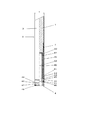
まず、本発明を実施するための形態として、棒状化粧料1の下方に繰り出し機構10を配置した繰り出し構造体Aから成る棒状化粧料繰り出し容器について図1〜図4及び図9により説明する。
First, as a mode for carrying out the present invention, a rod-shaped cosmetics feeding container composed of a feeding structure A in which a
口紅、スティックファンデーションなどの棒状化粧料1の下端を保持する紅皿2は、下端に脚筒20を垂下している。この脚筒20は、下部外側壁にガイド突部21を突設している。また、脚筒20の下端よりは、一対の切り欠き22が設けられ、ガイド突部21を設けた脚筒20を内方向に窄めることができるようになっている。さらに脚筒20の下部内面には、雌ネジ23を螺設している。この紅皿2は、スリーブ3内に上下摺動可能に内装されている。
The
スリーブ3は、肉薄金属製のパイプで、商品を差別化する加飾を施している。このスリーブ3の下部側面には、軸線と平行にガイド溝30を穿設している。このガイド溝30は、前記紅皿2のガイド突部21が係合して紅皿2を回動不能に摺動可能に案内している。またこのガイド溝30の長さによって、紅皿2のストローク(摺動長さ)が決定する。このガイド溝30には、紅皿2の脚筒20を内方向に窄めた状態で挿入し、ガイド突部21を係合させる。このスリーブ3の下端には、ネジ筒4を挿入している。
The
このネジ筒4は、紅皿2の脚筒20内に侵入するネジ部40と、スリーブ3後端より突出する連結部41より成っている。このネジ部40の外側壁には、紅皿2の脚筒20に設けた雌ネジ23と螺合する雄ネジ42を螺設している。連結部41は、スリーブ3後端部分が嵌合する上部連結部位43と、スリーブ3下端より外部に突出する下部連結部位44より成っている。
The
この上部連結部位43の外側壁には、2つの周溝(第1周溝45、第2周溝46)を刻設している。この第1周溝45には、スリーブ3の内周リブ31が回動自在に脱落不能に係合している。この内周リブ31は、スリーブ3の外部より内周方向に向けて成形している。第2周溝46には、Oリング11が嵌合している。このOリング11は、NBRなどの弾性を有した素材より成り、スリーブ3の内壁に弾性を有して摺接している。下部連結部位44の外周壁には、溝状の係合部47を周設し、この係合部47の下方側壁には、全周に軸線と平行に多数の縦溝48を刻設している。
Two peripheral grooves (first
上記紅皿2、スリーブ3、ネジ筒4により、繰り出し構造体Aを構成している。この繰り出し構造体Aは、スリーブ3とスリーブ3の下端より突出したネジ筒4の連結部41を相対回転すると、スリーブ3のガイド溝30により回動を阻止された紅皿2の脚筒20内の雌ネジ23が、ネジ筒4の雄ネジ42と螺合しているため、螺合作用により紅皿2が進退する繰り出し機構10を有している。このスリーブ3とネジ筒4の相対回転時に、ネジ筒4の第2周溝46内のOリング11がスリーブ3内壁に弾性を有して当接しているため、摺動抵抗が生じる。この摺動抵抗が良好な回転操作感を生む。
The feeding structure A is composed of the
この繰り出し構造体Aは、外装体Bに装着する。この外装体Bは、図示しないが繰り出し構造体A上部を覆うキャップと、中筒5と、本体筒9とより成っており、露出部分に商品を差別化する加飾を施している。中筒5は本体筒9上端に止着され、上部が本体筒9より上方に突出しキャップが抜脱可能に嵌合する嵌合部51になっている。この嵌合部51よりは、繰り出し構造体Aが差し込まれる。中筒5の内壁には、下方が大径となった上部当接部56を設けている。また、本体筒9の上部内側壁には、上方が大径となった下部当接部90を設け、中筒5の上部当接部56と本体筒9の下部当接部90の間に凹所53を構成している。更に本体筒9の下部内側壁には、繰り出し構造体Aの連結部41を係合保持する構造体保持部91を設けている。
The feeding structure A is attached to the exterior body B. Although not shown, the exterior body B is composed of a cap covering the upper part of the feeding structure A, a
この本体筒9の構造体保持部91内壁には、抜け止め突部92及び、回り止め突部93を突設している。この抜け止め突部92は、前記繰り出し構造体Aの連結部41に設けた溝状の係合部47と係合して繰り出し構造体Aを脱落不能に保持する。また、回り止め突部93は、前記繰り出し構造体Aの連結部41に設けた縦溝48と係合し繰り出し構造体Aのネジ筒4を回動不能に保持する。その結果、外装体Bと繰り出し構造体Aの連結部41は従動する。
A retaining
中筒5と本体筒9で構成される凹所53には、当接筒6を内装している(図4参照)。この当接筒6の側壁には肉薄部分64を設け、この肉薄部分64を「く」字形状に内方向に突出させてジャバラ状の当接部60を構成している。この当接部60はある程度の弾性で変形可能となっており、無負荷の状態(当接筒6単独の状態、図9参照)で、当接部60の内径α2が前記スリーブ3の外径βよりも僅かに大径で、組み立て時のスリーブ3挿入に支障がない。しかし、凹所53に装着して、当接筒6を中筒5と本体筒9の間に挟み込むと、図4に示した様に、当接部60が外装体Bに差し込まれた繰り出し構造体Aのスリーブ3と相対し窄まり、当接筒6の内径αがスリーブ3の外径βと同径か僅かに小径となり、スリーブ3(繰り出し構造体A)をある程度の弾性で軸心15に支持する。
A
更に、発明を実施するための他の実施形態として、繰り出し機構10を棒状化粧料1の周囲に配置した繰り出し構造体Aから成る棒状化粧料繰り出し容器について図5〜図9によって説明する。
Further, as another embodiment for carrying out the invention, a rod-shaped cosmetics feeding container composed of a feeding structure A in which the
口紅、スティックファンデーションなどの棒状化粧料1の下端を保持する紅皿2は、外側壁に一対の螺合突部24を突設している。この紅皿2は、身筒7内に上下摺動可能に内装されている。
The
この身筒7の棒状化粧料1及び紅皿2を収納した収納部70の外側壁には、螺旋保持部71を設けている。この螺旋保持部71の側壁には、軸線と平行に一対のガイド溝30を穿設している。このガイド溝30は、前記紅皿2の螺合突部24が貫通して紅皿2を回動不能に摺動可能に案内している。また、このガイド溝30の長さによって、紅皿2のストローク(摺動長さ)が決定する。この身筒7の収納部70の下方には、連結部41を設けている。また、螺旋保持部71には、ラセン筒8を回動自在に脱落不能に保持している。
A
このラセン筒8の内側壁には、前記身筒7のガイド溝30を貫通した紅皿2の螺合突部24が螺合するラセン溝80を螺設している。また、ラセン筒8の下部外周に軸線と平行の外周ローレット81を刻設している。このラセン筒8及び身筒7は、スリーブ3内に挿入されている。
A
このスリーブ3は、商品を差別化する加飾を施しており、内側壁には、ラセン筒8の外周ローレット81が係合してラセン筒8を回動不能に保持する内周ローレット32を刻設している。この内周ローレット32により、スリーブ3の回転に従ってラセン筒8が従動するようになっている。前記身筒7の連結部41は、スリーブ3の後端部分が嵌合する上部連結部位43と、スリーブ3後端より外部に突出する下部連結部位44より成っている。
The
この上部連結部位43の外側壁には、2つの周溝(第1周溝45、第2周溝46)を刻設している。この第1周溝45には、Oリング11が嵌合している。このOリング11は、NBRなどの弾性を有した素材より成り、スリーブ3の内壁に弾性を有して摺接している。第2周溝46には、スリーブ3の内周リブ31が回動自在に脱落不能に係合している。この内周リブ31は、スリーブ3の外部より内周方向に向けて成形している。下部連結部位44の外周壁には、溝状の係合部47を周設し、この係合部47の下方側壁には、全周に軸線と平行に多数の縦溝48を刻設している。
Two peripheral grooves (first
上記紅皿2、スリーブ3、身筒7、ラセン筒8により、繰り出し構造体Aを構成している。この繰り出し構造体Aは、スリーブ3とスリーブ3下端より突出した身筒7の連結部41を相対回転すると、身筒7のガイド溝30により回動を阻止された紅皿2の螺合突部24がスリーブ3に従動するラセン筒8のラセン溝80と螺合しているため、螺合作用により紅皿2が進退する繰り出し機構10を有している。このスリーブ3と身筒7の相対回転時に、身筒7の第1周溝46内のOリング11がスリーブ3内壁に弾性を有して当接しているため、摺動抵抗が生じる。この摺動抵抗が良好な回転操作感を生む。
The feeding structure A is composed of the
この繰り出し構造体Aは、外装体Bに装着する。この外装体Bは、図示しないが繰り出し構造体Aの上部を覆うキャップと、中筒5と、本体筒9とより成っており、露出部分に商品を差別化する加飾を施している。中筒5は、本体筒9の上端に止着され、上部が本体筒9より突出しキャップが抜脱可能に嵌合する嵌合部51になっている。この嵌合部51よりは、繰り出し構造体Aが差し込まれる。中筒5の内壁には、下方が大径となった上部当接部56を設けている。また、本体筒9の上部内側壁には、上方が大径となった下部当接部90を設け、中筒5の上部当接部56と本体筒9の下部当接部90の間に凹所53を構成している。この本体筒9の下部内側壁には、繰り出し構造体Aの連結部41を係合保持する構造体保持部91を設けている。
The feeding structure A is attached to the exterior body B. Although not shown, the exterior body B is composed of a cap covering the upper part of the feeding structure A, a
この本体筒9の構造体保持部91内壁には、抜け止め突部92及び、回り止め突部93を突設している。この抜け止め突部92は、前記繰り出し構造体Aの連結部41に設けた溝状の係合部47と係合して繰り出し構造体Aを脱落不能に保持する。また、回り止め突部93は、前記繰り出し構造体Aの連結部41に設けた縦溝48と係合し繰り出し構造体Aのネジ筒4を回動不能に保持する。その結果、外装体Bと繰り出し構造体Aの連結部41は従動する。
A retaining
中筒5と本体筒9とで構成される凹所53には、当接筒6を内装している(図8参照)。この当接筒6の側壁には肉薄部分64を設け、この肉薄部分64を「く」字形状に内方向に突出させてジャバラ状の当接部60を構成している。この当接部60はある程度の弾性で変形可能となっており、無負荷の状態(当接筒6単独の状態、図9参照)で、当接部60の内径α2が前記スリーブ3の外径βよりも僅かに大径で、組み立て時のスリーブ3挿入に支障がない。しかし、凹所53に装着して、当接筒6を中筒5と本体筒9の間に挟み込むと、図8に示した様に、当接部60が外装体Bに差し込まれた繰り出し構造体Aのスリーブ3と相対し窄まり、当接筒6の内径αがスリーブ3の外径βと同径か僅かに小径となり、スリーブ3(繰り出し構造体A)をある程度の弾性で軸心15に支持する。なお、この当接部60は、図10に示すように先端61を尖った形状にしてスリーブ3外壁に線接触しているため、スリーブ3外壁との間に発生する摺動抵抗は僅かであり、容器の操作感に影響を与えていない。
A
本発明を実施する場合の棒状化粧料繰り出し容器は、外部に露出したスリーブ3と下端の連結部41を相対回転させる事により駆動する繰り出し機構10を有した繰り出し構造部Aの連結部41を外装体Bに連結しており、外装体Bの中筒5と本体筒9の間の内側壁に当接筒6を挟み込み保持できる凹所53を、繰り出し構造体Aのスリーブ3と相対する位置に設ける事が出来れば実施可能である。従って、繰り出し構造部A中の繰り出し機構10も前述した条件を満たせば自由に選択でき、付帯するOリング11などの重み出し機構も自由に設定できる。さらに、実施形態2の構成の場合、スリーブ3とラセン筒8を一体に成形するなど、部品の一体化も可能である。
In the case of carrying out the present invention, the rod-shaped cosmetics feeding container has an exterior of the connecting
実施形態の欄において、繰り出し構造体Aと外装体Bの連結は、係合部47と抜け止め突部92の係合、及び縦溝48と回り止め突部93の係合による方法を述べたが、これら係合による連結方法ばかりでなく、カシメ加工、接着など、繰り出し構造体Aと外装体Bを直接固定する方法も実施可能である。
In the column of the embodiment, the method of connecting the feeding structure A and the exterior body B by engaging the engaging
繰り出し構造体Aと外装体Bを、係合部47と抜け止め突部92の係合、及び縦溝48と回り止め突部93の係合など、係合により連結させた場合、抜脱可能に係合保持させることにより、繰り出し構造体Aを任意に取り外しできるカートリッジ式棒状化粧料繰り出し容器として利用できる。
When the feeding structure A and the exterior body B are connected by engagement such as engagement between the engaging
当接筒6は、中筒5と本体筒9の間に挟み込まれる事により当接部60が変形して内径が窄まり、繰り出し構造体Aのスリーブ3を軸心15に支持するため、当接筒6全体をNBR、エラストマー樹脂などの弾性変形可能な素材で成形しても、図5に示す様に、当接部を肉薄のジャバラ形状に成形して当接部60にのみ変形可能に構成してもよい。なお、この弾性は繰り出し構造体Aを軸心15に支持するのに必要最小限の弾性であれば良く、必ずしも復元性を有する必要はない。
Since the
当接筒6の当接部60は図9に示した様にジャバラ形状であるが、さらに図10に示す様に、当接部60に切り欠き65を設けて当接部60を変形し易くしても良い。この場合、スリーブ3の外壁に間欠に線接触するのであるが、切り欠き65を均等に配置すれば、スリーブ3を問題なく軸心15に保持できる。また、操作感に悪影響を与える事もない。
The
1 棒状化粧料
3 スリーブ
5 中筒
6 当接筒
9 本体筒
10 繰り出し機構
15 軸心
41 連結部
51 嵌合部
53 凹所
60 当接部
61 先端
A 繰り出し構造体
B 外装体
α 内径
β スリーブ外径
1 Rod-shaped
Claims (1)
前記中筒(5)と本体筒(9)の間の凹所(53)に、スリーブ(3)が貫通する当接筒(6)を挟持し、該当接筒(6)の前記繰り出し構造体(A)のスリーブ(3)と相対した内周壁に、先端(61)が尖った「く」字形状のジャバラ状をした変形可能な当接部(60)を突設し、該当接部(60)は当接筒(6)が前記中筒(5)と本体筒(9)の間に挟持される事により弾性変形して内径が窄まり、スリーブ外径(β)と同径か僅かに小径となってスリーブ(3)外壁に線接触し、スリーブ(3)と外装体(B)の相対回転時の摺動抵抗は僅かであるが、スリーブ(3)を軸芯(15)に支え、繰り出し構造体(A)の横振れを抑えることを特徴とする棒状化粧料繰り出し容器。 A sleeve is provided with a feeding mechanism (10) that holds the rod-shaped cosmetic (1) and slides the rod-shaped cosmetic (1) up and down by the relative rotation of the sleeve (3) exposed to the outside and the connecting portion (41) at the lower end. A feeding structure (A) in which an O-ring (11) having elasticity and sliding contact is arranged between the relative rotating portions of the connecting portion (3) and the connecting portion (41), and the upper portion of the feeding structure (A). An exterior body (B) composed of a middle cylinder (5) having a fitting portion (51) to which a cap to be covered is detachably fitted, and a main body cylinder (9) to which the middle cylinder (5) is fastened. The feeding structure (A) is inserted into the outer body (B) from the fitting portion (51), and the connecting portion (41) and the outer body (B) of the feeding structure (A) are fastened to each other. In a configuration in which the exterior body (B) and the feeding structure (A) are connected and the connecting portion (41) of the feeding structure (A) can be operated by the exterior body (B).
A contact cylinder (6) through which the sleeve (3) penetrates is sandwiched in a recess (53) between the middle cylinder (5) and the main body cylinder (9), and the feeding structure of the corresponding contact cylinder (6). On the inner peripheral wall facing the sleeve (3) of (A), a deformable contact portion (60) having a "dogleg" shape with a pointed tip (61) is projected, and the corresponding contact portion ( In 60), the contact cylinder (6) is sandwiched between the middle cylinder (5) and the main body cylinder (9), so that the contact cylinder (6) is elastically deformed and the inner diameter is narrowed. The diameter is reduced to the outer wall of the sleeve (3), and the sliding resistance of the sleeve (3) and the exterior body (B) during relative rotation is small, but the sleeve (3) is used as the shaft core (15). A rod-shaped cosmetics feeding container characterized by supporting and suppressing lateral vibration of the feeding structure (A).
Priority Applications (1)
| Application Number | Priority Date | Filing Date | Title |
|---|---|---|---|
| JP2016163266A JP6942945B2 (en) | 2016-08-24 | 2016-08-24 | Stick-shaped cosmetics delivery container |
Applications Claiming Priority (1)
| Application Number | Priority Date | Filing Date | Title |
|---|---|---|---|
| JP2016163266A JP6942945B2 (en) | 2016-08-24 | 2016-08-24 | Stick-shaped cosmetics delivery container |
Publications (3)
| Publication Number | Publication Date |
|---|---|
| JP2018029744A JP2018029744A (en) | 2018-03-01 |
| JP2018029744A5 JP2018029744A5 (en) | 2019-09-19 |
| JP6942945B2 true JP6942945B2 (en) | 2021-09-29 |
Family
ID=61304142
Family Applications (1)
| Application Number | Title | Priority Date | Filing Date |
|---|---|---|---|
| JP2016163266A Active JP6942945B2 (en) | 2016-08-24 | 2016-08-24 | Stick-shaped cosmetics delivery container |
Country Status (1)
| Country | Link |
|---|---|
| JP (1) | JP6942945B2 (en) |
Families Citing this family (1)
| Publication number | Priority date | Publication date | Assignee | Title |
|---|---|---|---|---|
| CN113243651B (en) * | 2020-02-13 | 2023-03-10 | 阿蓓亚塑料实业(上海)有限公司 | Mechanism for a cosmetic container and container comprising such a mechanism |
Family Cites Families (11)
| Publication number | Priority date | Publication date | Assignee | Title |
|---|---|---|---|---|
| JPS62183708A (en) * | 1986-02-07 | 1987-08-12 | 株式会社 飛弾製作所 | Rod shaped cosmetics container |
| JP2707485B2 (en) * | 1994-06-23 | 1998-01-28 | 株式会社カツシカ | Feeding mechanism |
| JP2879653B2 (en) * | 1995-03-31 | 1999-04-05 | 株式会社ヒダン | Cosmetic container |
| JP3185203B2 (en) * | 1995-04-05 | 2001-07-09 | 株式会社カツシカ | Stick-shaped cosmetic dispensing container |
| JP2791652B2 (en) * | 1995-10-31 | 1998-08-27 | 株式会社ヒダン | Cosmetic container |
| JPH10243816A (en) * | 1997-03-07 | 1998-09-14 | Suzuno Kasei Kk | Delivery container for bar-shaped cosmetic material |
| JP3994182B2 (en) * | 1997-12-25 | 2007-10-17 | 株式会社吉野工業所 | Feeding container |
| JP3675176B2 (en) * | 1998-06-19 | 2005-07-27 | 株式会社カツシカ | Stick-shaped cosmetics delivery container |
| JP3622784B2 (en) * | 2000-12-28 | 2005-02-23 | ロート製薬株式会社 | Formulation container |
| JP4775754B2 (en) * | 2004-09-22 | 2011-09-21 | 株式会社カツシカ | Stick-shaped cosmetics delivery container |
| JP6161935B2 (en) * | 2013-04-08 | 2017-07-12 | 株式会社カツシカ | Stick-shaped cosmetics delivery container |
-
2016
- 2016-08-24 JP JP2016163266A patent/JP6942945B2/en active Active
Also Published As
| Publication number | Publication date |
|---|---|
| JP2018029744A (en) | 2018-03-01 |
Similar Documents
| Publication | Publication Date | Title |
|---|---|---|
| US4617948A (en) | Make-up unit, for eyelashes in particular | |
| US7448393B2 (en) | Cosmetic brush | |
| US8783987B2 (en) | Wiper with resilient wiper lamellas | |
| US3469928A (en) | Applicator | |
| US9004075B2 (en) | Wiper for a cosmetic container | |
| CN108720239B (en) | Stick-shaped cosmetic push-out container | |
| US8562232B2 (en) | Stick-shaped cosmetic material feeding container | |
| CN108143077A (en) | For the container of club-shaped material | |
| CN107048674A (en) | By starting writing | |
| JP6942945B2 (en) | Stick-shaped cosmetics delivery container | |
| KR101794508B1 (en) | Lipstick case to prevent the flow of lipstick holder | |
| CN207837036U (en) | Container for club-shaped material | |
| JP2006204415A (en) | Delivery cylinder and stick-shaped cosmetic delivery container using the same | |
| JP6600489B2 (en) | Rotating feeding container | |
| JP2003159119A (en) | Rod-shaped cosmetic screw-out container | |
| JP2002262936A (en) | Feeding container for stick cosmetic | |
| JP2009022755A (en) | Applicator device for application of liquid medium | |
| JP4738072B2 (en) | Application container | |
| JP2014205242A (en) | Writing instrument | |
| JP6817046B2 (en) | Feeding container | |
| JP6980347B2 (en) | Lipstick container | |
| JP3098150B2 (en) | Stick-shaped cosmetic dispensing container | |
| JP7254487B2 (en) | fixed delivery container | |
| JP2918107B2 (en) | Stick-shaped cosmetic dispensing container | |
| JP4991215B2 (en) | Stick-shaped cosmetic material feeding container |
Legal Events
| Date | Code | Title | Description |
|---|---|---|---|
| A521 | Written amendment |
Free format text: JAPANESE INTERMEDIATE CODE: A523 Effective date: 20190807 |
|
| A621 | Written request for application examination |
Free format text: JAPANESE INTERMEDIATE CODE: A621 Effective date: 20190807 |
|
| A977 | Report on retrieval |
Free format text: JAPANESE INTERMEDIATE CODE: A971007 Effective date: 20200730 |
|
| A131 | Notification of reasons for refusal |
Free format text: JAPANESE INTERMEDIATE CODE: A131 Effective date: 20200824 |
|
| A521 | Written amendment |
Free format text: JAPANESE INTERMEDIATE CODE: A523 Effective date: 20201005 |
|
| A131 | Notification of reasons for refusal |
Free format text: JAPANESE INTERMEDIATE CODE: A131 Effective date: 20210419 |
|
| A521 | Written amendment |
Free format text: JAPANESE INTERMEDIATE CODE: A523 Effective date: 20210611 |
|
| TRDD | Decision of grant or rejection written | ||
| A01 | Written decision to grant a patent or to grant a registration (utility model) |
Free format text: JAPANESE INTERMEDIATE CODE: A01 Effective date: 20210810 |
|
| A61 | First payment of annual fees (during grant procedure) |
Free format text: JAPANESE INTERMEDIATE CODE: A61 Effective date: 20210823 |
|
| R150 | Certificate of patent or registration of utility model |
Ref document number: 6942945 Country of ref document: JP Free format text: JAPANESE INTERMEDIATE CODE: R150 |